EP3660331A1 - Filter retaining plug and tool - Google Patents
Filter retaining plug and tool Download PDFInfo
- Publication number
- EP3660331A1 EP3660331A1 EP18461630.8A EP18461630A EP3660331A1 EP 3660331 A1 EP3660331 A1 EP 3660331A1 EP 18461630 A EP18461630 A EP 18461630A EP 3660331 A1 EP3660331 A1 EP 3660331A1
- Authority
- EP
- European Patent Office
- Prior art keywords
- plug
- tool
- port
- recess
- rod
- Prior art date
- Legal status (The legal status is an assumption and is not a legal conclusion. Google has not performed a legal analysis and makes no representation as to the accuracy of the status listed.)
- Granted
Links
Images



Classifications
-
- F—MECHANICAL ENGINEERING; LIGHTING; HEATING; WEAPONS; BLASTING
- F16—ENGINEERING ELEMENTS AND UNITS; GENERAL MEASURES FOR PRODUCING AND MAINTAINING EFFECTIVE FUNCTIONING OF MACHINES OR INSTALLATIONS; THERMAL INSULATION IN GENERAL
- F16K—VALVES; TAPS; COCKS; ACTUATING-FLOATS; DEVICES FOR VENTING OR AERATING
- F16K3/00—Gate valves or sliding valves, i.e. cut-off apparatus with closing members having a sliding movement along the seat for opening and closing
- F16K3/02—Gate valves or sliding valves, i.e. cut-off apparatus with closing members having a sliding movement along the seat for opening and closing with flat sealing faces; Packings therefor
- F16K3/0209—Gate valves or sliding valves, i.e. cut-off apparatus with closing members having a sliding movement along the seat for opening and closing with flat sealing faces; Packings therefor the valve having a particular passage, e.g. provided with a filter, throttle or safety device
-
- F—MECHANICAL ENGINEERING; LIGHTING; HEATING; WEAPONS; BLASTING
- F15—FLUID-PRESSURE ACTUATORS; HYDRAULICS OR PNEUMATICS IN GENERAL
- F15B—SYSTEMS ACTING BY MEANS OF FLUIDS IN GENERAL; FLUID-PRESSURE ACTUATORS, e.g. SERVOMOTORS; DETAILS OF FLUID-PRESSURE SYSTEMS, NOT OTHERWISE PROVIDED FOR
- F15B13/00—Details of servomotor systems ; Valves for servomotor systems
- F15B13/02—Fluid distribution or supply devices characterised by their adaptation to the control of servomotors
- F15B13/04—Fluid distribution or supply devices characterised by their adaptation to the control of servomotors for use with a single servomotor
- F15B13/042—Fluid distribution or supply devices characterised by their adaptation to the control of servomotors for use with a single servomotor operated by fluid pressure
- F15B13/043—Fluid distribution or supply devices characterised by their adaptation to the control of servomotors for use with a single servomotor operated by fluid pressure with electrically-controlled pilot valves
-
- B—PERFORMING OPERATIONS; TRANSPORTING
- B01—PHYSICAL OR CHEMICAL PROCESSES OR APPARATUS IN GENERAL
- B01D—SEPARATION
- B01D29/00—Filters with filtering elements stationary during filtration, e.g. pressure or suction filters, not covered by groups B01D24/00 - B01D27/00; Filtering elements therefor
- B01D29/01—Filters with filtering elements stationary during filtration, e.g. pressure or suction filters, not covered by groups B01D24/00 - B01D27/00; Filtering elements therefor with flat filtering elements
- B01D29/05—Filters with filtering elements stationary during filtration, e.g. pressure or suction filters, not covered by groups B01D24/00 - B01D27/00; Filtering elements therefor with flat filtering elements supported
-
- B—PERFORMING OPERATIONS; TRANSPORTING
- B23—MACHINE TOOLS; METAL-WORKING NOT OTHERWISE PROVIDED FOR
- B23P—METAL-WORKING NOT OTHERWISE PROVIDED FOR; COMBINED OPERATIONS; UNIVERSAL MACHINE TOOLS
- B23P19/00—Machines for simply fitting together or separating metal parts or objects, or metal and non-metal parts, whether or not involving some deformation; Tools or devices therefor so far as not provided for in other classes
- B23P19/04—Machines for simply fitting together or separating metal parts or objects, or metal and non-metal parts, whether or not involving some deformation; Tools or devices therefor so far as not provided for in other classes for assembling or disassembling parts
-
- B—PERFORMING OPERATIONS; TRANSPORTING
- B25—HAND TOOLS; PORTABLE POWER-DRIVEN TOOLS; MANIPULATORS
- B25B—TOOLS OR BENCH DEVICES NOT OTHERWISE PROVIDED FOR, FOR FASTENING, CONNECTING, DISENGAGING, OR HOLDING
- B25B27/00—Hand tools, specially adapted for fitting together or separating parts or objects whether or not involving some deformation, not otherwise provided for
- B25B27/02—Hand tools, specially adapted for fitting together or separating parts or objects whether or not involving some deformation, not otherwise provided for for connecting objects by press fit or detaching same
- B25B27/023—Hand tools, specially adapted for fitting together or separating parts or objects whether or not involving some deformation, not otherwise provided for for connecting objects by press fit or detaching same using screws
-
- F—MECHANICAL ENGINEERING; LIGHTING; HEATING; WEAPONS; BLASTING
- F15—FLUID-PRESSURE ACTUATORS; HYDRAULICS OR PNEUMATICS IN GENERAL
- F15B—SYSTEMS ACTING BY MEANS OF FLUIDS IN GENERAL; FLUID-PRESSURE ACTUATORS, e.g. SERVOMOTORS; DETAILS OF FLUID-PRESSURE SYSTEMS, NOT OTHERWISE PROVIDED FOR
- F15B21/00—Common features of fluid actuator systems; Fluid-pressure actuator systems or details thereof, not covered by any other group of this subclass
- F15B21/04—Special measures taken in connection with the properties of the fluid
- F15B21/041—Removal or measurement of solid or liquid contamination, e.g. filtering
Definitions
- the tool may further comprise a key formation for engagement with a key member to rotate the rod.
- a servovalve 2 comprises a servovalve housing 4 which houses a pair of nozzles 6 and a flapper element 8.
- the flapper element 8 is deflected in a direction along the axes of the nozzles 6 by an actuator, not shown, in order to meter a working fluid which passes through the nozzles 6.
Landscapes
- Engineering & Computer Science (AREA)
- Mechanical Engineering (AREA)
- General Engineering & Computer Science (AREA)
- Physics & Mathematics (AREA)
- Fluid Mechanics (AREA)
- Chemical & Material Sciences (AREA)
- Analytical Chemistry (AREA)
- Chemical Kinetics & Catalysis (AREA)
- Details Of Valves (AREA)
- Lift Valve (AREA)
Abstract
Description
- The present disclosure relates to plugs which are used to retain a filter in, for example, a servovalve and to tools which may be used in removing such plugs.
- Servovalves are used in a wide variety of aircraft control systems, for example in fuel and air management systems for operating engine fuel metering valves, active clearance control valves, bleed valves and so on. The operating medium of the servovalve will potentially be contaminated. Accordingly, servovalves are provided with filters. Such filters may include filter screens which are assembled in ports of the servovalve, for example in supply, control or return ports of the valve. These screens act to retain any particles which are large enough potentially to cause potential failure of the valve. For example in a flapper type servovalve, comprising two nozzles and a movable flapper element arranged between them, the total flapper operating total distance may be as small as about 0.2mm. In such valves, the filter screen will typically act to filter out particles having a nominal size larger than 0.07mm. Such filter screens can easily become blocked. This necessitates cleaning or removal and replacement of the filter screens. However, this may be difficult as the filter screen is typically retained by a press fitted plug. Removal of this plug is difficult and may cause damage to the servovalve body, requiring the servovalve itself then to require repair.
- From a first aspect, the disclosure provides a plug for retaining a filter screen in a fluid port of a servovalve, the plug comprising an annular body, the annular body comprising opposed first and second axial annular end surfaces. A radially inner surface extends between the first and second axial annular end surfaces and a radially outer surface extends between the first and second axial annular end surfaces. At least one recess is formed in the radially inner surface for receiving a tool for removing the plug from the port. A plurality of slots is formed in the first axial annular end surface and extends into the at least one recess for providing access for the tool to the at least one recess.
- The slots may be are evenly annularly distributed around the first axial annular end surface.
- The plurality of slots may comprise two diametrically opposed slots.
- Each slot may have a radial width between 40% to 100% of the radial width of the first axial annular end surface.
- Each
slot 25 may have a length between 30% and 40% of the outer diameter of the plug body measured between opposing points on the radially outer surface. - Each slot may comprise two side surfaces with chamfered or rounded top edges and/or chamfered or rounded bottom edges.
- The disclosure also provides a servovalve comprising a port for receiving an working fluid, a filter screen mounted in the port and a plug in accordance with the disclosure interference fitted in the port to retain the filter screen in the port.
- This disclosure also provides a tool for removing a plug in accordance with the disclosure from a port, the tool comprising a rod having an upper portion, a lower portion comprising a plurality of outwardly projecting teeth for engaging in the recess of the plug annular body and locking the lower portion in the plug annular body, and an externally threaded portion between the lower portion and the upper portion. A nut is engageable with the externally threaded portion and rotatable to remove the rod and plug from the port. A sleeve is configured to be positioned on the rod between the nut and the plug.
- The tool may further comprise a key formation for engagement with a key member to rotate the rod.
- The teeth may comprise chamfered or rounded edges.
- The height of the teeth may be between 80% and 90% of the height of the recess.
- The lower portion of the rod may have a portion with smaller diameter than the externally threaded portion. The lower portion of the rod may optionally have a tapered neck between the portion and the externally threaded portion.
- This disclosure also provides a method of removing a filter screen retaining plug from a fluid port of a servovalve, the method comprising inserting an end of a removal tool into the plug, rotating the removal tool to lock the end of the removal tool inside the plug, and applying a force to the removal tool in a direction away from the fluid port and parallel to the longitudinal axis of the fluid port to disengage the plug from the fluid port.
- The force may be applied by rotating a nut threaded onto a rod of the removal tool.
- This disclosure also provides a method of maintaining a servovalve comprising a fluid port and a filter screen retained in the fluid port by a plug in accordance with the disclosure interference fitted within the fluid port, comprising engaging a removal tool with the at least one recess of the plug body and pulling the plug out of the port using the tool. The removal tool is optionally a tool in accordance with the disclosure.
-
-
Figure 1 shows a cross-section through a servovalve in accordance with the disclosure; -
Figure 2 shows an exploded view of the servovalve ofFigure 1 ; -
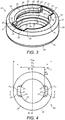
Figure 3 shows a perspective view of a plug in accordance with the disclosure; -
Figure 4 shows a plan view of the plug ofFigure 3 ; -
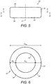
Figure 5 shows a side view of the plug ofFigure 3 ; -
Figure 6 shows a bottom view of the plug ofFigure 3 ; -
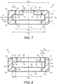
Figure 7 shows a cross-sectional view of the plug ofFigure 4 along the line B-B ofFigure 4 ; -
Figure 8 shows a cross-sectional view of the plug ofFigure 4 along the line C-C ofFigure 4 ; -
Figure 9 shows a cross-sectional view of the plug ofFigure 5 along the line D-D ofFigure 5 ; -
Figure 10 shows a cross-sectional view of the plug ofFigure 6 along the line E-E ofFigure 5 ; -
Figure 11 shows an exploded view of a servovalve, plug and plug removal tool in accordance with the disclosure; -
Figure 12 shows a side view of the plug removal tool in accordance with the disclosure; -
Figure 13 shows a cross-sectional view of the plug removal tool ofFigure 12 ; -
Figure 14 shows a perspective view of the servovalve and plug removal tool ofFigure 11 in a removal configuration engaged with the plug; -
Figure 15 shows a perspective cross-sectional view of the servovalve, plug and plug removal tool ofFigure 11 in a removal configuration engaged with the plug; -
Figure 16 shows a cross-sectional view of the servovalve, plug and plug removal tool ofFigure 11 in a removal configuration engaged with the plug; -
Figure 17 shows a close-up perspective view of the servovalve, plug and plug removal tool prior to engagement of the tool with the plug, with the tool in an insertion position; -
Figure 18 shows a close-up perspective view of the servovalve, plug and plug removal tool in a removal configuration with the tool engaged with the plug and in a locked position; -
Figure 19 shows a cross-sectional view of the servovalve, plug and plug removal tool ofFigure 18 , corresponding to the cross-sectional views of the plug ofFigure 7 and the tool ofFigure 13 ; and -
Figure 20 shows another cross-sectional view of the plug and plug removal tool ofFigure 18 , corresponding to the cross-sectional view of the plug ofFigure 9 . - With reference to
Figures 1 and 2 , aservovalve 2 comprises aservovalve housing 4 which houses a pair ofnozzles 6 and aflapper element 8. As is known in the art, theflapper element 8 is deflected in a direction along the axes of thenozzles 6 by an actuator, not shown, in order to meter a working fluid which passes through thenozzles 6. - The
servovalve housing 4 comprises threeports 10, which allow communication of the working fluid to thenozzles 6. Thecentral port 10 is typically called a control port and its function is to communicate fluid to an actuator (not shown). This type of servovalve is well known in the art, being used in a wide variety of aircraft control systems, for example in fuel and air management systems for operating engine fuel metering valves, active clearance control valves, bleed valves and so on. - Since, as is discussed above, the distances moved by the
flapper element 8 may be relatively small, in order to prevent operation of theflapper element 8 being compromised by contamination,particle filters 14 are arranged in one or more of theports 10. As can be seen inFigure 1 , in an embodiment of the disclosure, thefilters 14 are received within abore 16 of therespective ports 10 and are received on anannular shoulder 18 at the base of each bore 16. - The
filter 14 may be a screen or mesh structure as is known in the art, with an appropriate mesh size. For example, in some embodiments thefilter 14 may be configured to filter particles having a nominal size larger than 0.07 mm. Thefilter 14 may be made from any suitable material, for example a metal or a plastics material. - The
filter 14 is retained on theshoulder 18 within thebore 16 by aplug 20 which is press fitted into thebore 16. With reference toFigures 3 to 10 , theplug 20 has anannular body 22 having opposed first and second axial annular end surfaces 24, 26, a radiallyinner surface 28 extending between the first and second axial annular end surfaces 24, 26 and a radiallyouter surface 30 extending between the first and second axial annular end surfaces 24, 26. The first and second axial annular end surfaces 24, 26 are generally parallel to one another and perpendicular to the central axis A of theplug 20. The radially inner andouter surfaces plug 20. - An
annular recess 36 is formed in the radiallyinner surface 28. In this embodiment, therecess 36 extends entirely around the circumference of theinner surface 28. In other embodiments, however, one or more pairs of diametrically opposed recesses may be provided instead. However, anannular recess 36 may be more easily manufactured and may facilitate removal of theplug 20. - The
recess 36 extends into theplug body 22 generally perpendicularly to the radiallyinner surface 28. In the disclosed embodiment, therecess 36 has opposedaxial surfaces base surface 42. Theaxial surfaces plug body 22. Thebase surface 42 may be parallel to the radially inner andouter surfaces plug body 22. - The
recess 36 may extend radially into theplug body 22 from the radiallyinner surface 28 to a depth D of from 30-50% of the thickness T of theplug body 22 measured between the radially inner and radiallyouter surfaces plug body 22. - The
recess 36 may have a height HR measured in the direction between its opposedaxial surfaces plug body 22 measured between the first and second axial annular end surfaces 24, 26 of theplug body 22. - In this embodiment, the radially
inner surface 28 has an inner diameter DPI which is the same on both sides of therecess 36. In other embodiments, the inner diameter DPI may be larger above the recess 36 (adjacent the first axial annular end surface 24) than below the recess 36 (adjacent the second axial annular end surface 26). In further embodiments, the inner diameter DPI may be smaller above therecess 36 than below therecess 36. - In a typical embodiment, the
plug body 22 may have an outer diameter DPO of 7.5 mm and an inner diameter DPI of 4.7 mm and therecess 36 may have an outer diameter DR of 6 mm. The inner diameter DPI of theplug body 22 will need to be large enough to allow the flow of working fluid through therespective ports 10. The height HP of theplug body 22 may typically be 2.7 mm and the height HR of therecess 36 may typically be 1 mm.
A pair of diametricallyopposed slots 25 are formed in the first axialannular end surface 24. Theslots 25 provide access for theteeth 64 of a plug removal tool to enter therecess 36 within theplug body 22, as will be discussed further below. Eachslot 25 extends radially from the radiallyinner surface 28, between theaxial surface 38 of therecess 36 and the first axialannular end surface 24, towards the radiallyouter surface 30. Eachslot 25 has a radial width WS between 40% and 100%, for example between 40% and 90%, of the radial width WR of the first axialannular end surface 24 measured between the radiallyinner surface 28 and the radiallyouter surface 30. Theslots 25 extend axially from the first axialannular end surface 24 to the top of therecess 36, thus providing an increased inner diameter DS in the dimension perpendicular to the inner diameter DPI shown inFigure 7 . - Each
slot 25 has parallel side surfaces 23 which correspond to the profile of theteeth 64 of thetool 50, as discussed below. The side surfaces 23 define a length LS of theslot 25. A typical length LS for aslot 25 is between 30% and 40% of the outer diameter DPO of theplug body 22 measured between opposing points on the radiallyouter surface 30. Eachslot 25 has a radiallyouter slot surface 27 that follows the curve of the first axialannular end surface 24 and is parallel to the radiallyouter surface 30 of theplug body 22. As can be seen inFigure 3 ,fillets 21 may be present where the side surfaces 23 join the radiallyouter surface 27 of eachslot 25. - The top and
bottom edges slots 25 and thetop edge 37 of the radiallyouter slot surface 27 are rounded or chamfered as shown inFigures 3 ,7 and 8 . Theedges 33 where the radiallyinner surface 28 meets the first axialannular end surface 24 and theedges 35 where the radiallyinner surface 28 meets theaxial surface 38 of therecess 36 are also rounded or chamfered, as shown inFigures 3 ,7 and 8 . The rounded or chamferededges tool 50 into therecess 36 and the removal of thetool 50 from therecess 36. The lack of sharp edges reduces the chances of loose material being scraped off or otherwise removed from theplug body 22 ortool 50 and causing damage by falling into thefluid port 10. - In this embodiment, the
plug 20 has two diametricallyopposed slots 25 formed in the first axialannular end surface 24. However, in other embodiments, theplug 20 may have more than twoslots 25, for example three or fourslots 25. It is also feasible that theplug 20 could have just oneslot 25, for example if the material of theplug body 22 is rigid enough to maintain its horizontal orientation when being removed by the application of an upward force on only one side of theplug body 22. Theslots 25 can be evenly distributed around the first axialannular end surface 24. - As can be seen in
Figures 3 ,7 and 8 , thecorners outer surface 30 may be chamfered or rounded in order to facilitate insertion of theplug 20 into thebore 16. - The
plug body 22 may be made from any suitable material. In certain embodiments, theplug body 22 may be made from aluminium for example. This will provide sufficient rigidity and strength for theplug body 22. - As discussed above, the
plug body 22 is press fitted into thebore 16 in order to retain thefilter 14 in position. Theslots 25 andrecess 36 facilitate removal of theplug 20 from thebore 16 as will be discussed further below. -
Figures 11 to 20 illustrate atool 50 which may be used in removing theplug 20 from abore 16. - The
tool 50 comprises arod 52,sleeve 54 andnut 56. Therod 52 has alower portion 58, anupper portion 60, and an externally threadedportion 62. Theupper portion 60 may also be externally threaded and the externally threadedportion 62 may have one or more parts without an external thread. Thelower portion 58 is sized and shaped to be received within theannular body 22 of theplug 20. Thelower portion 58 has a pair of diametrically opposed outwardly projectingteeth 64 which are sized and shaped to be received within theslots 25 of the first axialannular end surface 24 of theplug body 22. Due to the cooperation between theslots 25 and theteeth 64, the end of thelower portion 58, including theteeth 64, can be received by therecess 36 in theplug body 22. - The width WT of the
rod 52 between the radiallyouter surfaces 65 of theteeth 64 is larger than the inner diameter DPI of theplug body 22, therefore theaxial surface 40 which forms the base of therecess 36 prevents therod 52 from passing any lower through theplug body 22 as it has no slots for theteeth 64 to pass through. - The
slots 25 andteeth 64 are configured such that therod 52 can only be inserted into and removed from theplug body 22 in two configurations, when first andsecond teeth 64 are respectively aligned with the first andsecond slots 25. Therefore the width WT of therod 52 between the radiallyouter surfaces 65 of theteeth 64 is less than or equal to the increased inner diameter DS of theplug body 22 to allow thelower portion 58 of therod 52 to be at least partly inserted into theplug body 22 when therod 52 is in an insertion position and then rotated into a locked position with theteeth 64 and theslots 25 out of alignment. The width WT of therod 52 at theteeth 64 is therefore greater than the inner diameter DPI of theplug body 22 to provide the locking capability. - The
teeth 64 may have any suitable profile as long as they can pass through theslots 25 and be received within therecess 36. In this embodiment, the upper andlower surfaces tooth 64 are flat. This may facilitate the application of force from theteeth 64 to theplug body 22 as theplug 20 is being removed by maximising the surface area of theteeth 64 that is in contact with theaxial surface 28 of theplug body 22 when theplug 20 is being removed. - In embodiments, the relative dimensions of the
teeth 64 and therecess 36, such as the height HT of theteeth 64 and the height HR of therecess 36, may be such that therecess 36 provides a loose fit for theteeth 64. For a loose fit, the height HT of theteeth 64 is less than the height HR of therecess 36, for example HT is approximately 80% to 90% of HR. The diameter DR of therecess 36 is very slightly larger than the width WT of thetool 50 across theteeth 64 to enable thetool 50 to rotate. Thetool 50 can therefore be rotated easily with minimal contact and/or friction between the upper andlower surfaces teeth 64 and theaxial surfaces recess 36. - The
rod 52 has akey formation 66 in itsupper portion 60 which is sized and shaped to engage with a correspondingkey member 68 which can be used to rotate therod 52 about the longitudinal axis of therod 52. In this embodiment, thekey formation 66 is a hexagonal socket and thekey member 68 is anAllen key 68. In other embodiments, theupper portion 60 of therod 52 has an external key formation that can be received by a key member with an internal key formation to rotate therod 52. - The
rod 52 can also be rotated directly by hand, for example by gripping theupper portion 60 of therod 52, without requiring akey member 68 such as anAllen key 68. However, using a tool such as anAllen key 68 provides easier gripping of therod 52 and allows therod 52 to be turned more easily. - The lower surfaces 74 of each
tooth 64 are flush with the flatlower surface 76 of thelower portion 58 of therod 52, as can be seen fromFigures 12 and 13 . This avoids damage to thefilter screen 14 by thetool 50 since the lowermost part of thetool 50, thelower surface 76, can only extend as far down as theteeth 64 can, which is to the bottom of therecess 36. - The
teeth 64 have chamfered orrounded edges 78, as can be seen fromFigures 12 and 13 , which may facilitate the insertion of theteeth 64 through theslots 25 and into therecess 36 and the rotation of theteeth 64 in therecess 36. The lack of sharp edges also reduces the chances of loose material being scraped off or otherwise removed from theplug body 22 ortool 50 and causing damage by falling into thefluid port 10. Of course other shapes ofteeth 64 are possible within the scope of the disclosure. In this embodiment, theteeth 64 are the same size and shape, however in other embodiments theteeth 64 may differ from each other. - The
sleeve 54 acts as a spacer to separate thenut 56 from theplug 20 and the upper surface of theservovalve housing 4 around thefluid port 10. The prevention of contact between thenut 56 and theservovalve housing 4 is important to protect theservovalve housing 4 from damage due to friction resulting from the movement of thenut 56. Thesleeve 54 also facilitates the rotation of thenut 56. The externally threadedportion 62 of therod 52 enables the internally threadednut 56 to be threaded onto therod 52 and into abutment with thesleeve 54. Thenut 56 may be turned and tightened with aspanner 70, as shown inFigures 11 ,14 ,15 and16 . - The
lower portion 58 of therod 52 comprises acylindrical portion 57 with a diameter DC smaller than the diameter DE of the externally threadedportion 62 and aneck portion 59 which tapers from the larger diameter DE of the externally threadedportion 62 to the smaller diameter DC of thecylindrical portion 57. Theteeth 64 protrude from the base of thecylindrical portion 57. - The diameter DC of the cylindrical portion 57 (not including the teeth 64) being smaller than the diameter DE of the externally threaded
portion 62 allows thelower portion 58 to be small enough to fit within theplug body 22 while the externally threadedportion 62 is thick enough to provide sufficient strength to therod 52 so that therod 52 does not break or bend when thenut 56 is turned by thespanner 70. - Having described the
plug 20 andtool 50, removal of aplug 20 from abore 16 will now be described.Figures 17 to 20 illustrate the insertion and locked positions of therod 52. - Firstly, with the
rod 52 in the insertion position shown inFigure 17 , thelower portion 58 of therod 52 is inserted into theplug 20. As can be clearly seen fromFigure 17 , in the insertion position theteeth 64 of thelower portion 58 must be aligned with theslots 25 of theplug 20 in order for thelower portion 58 to be inserted into theplug 20. Therod 52 is inserted to such a depth that theteeth 64 are located within therecess 36. - The
rod 52 is then rotated to the locked position in which theteeth 64 are no longer aligned with theslots 25 of theplug 20, as shown inFigures 18 to 20 . Therod 52 can be rotated by inserting theAllen key 68 into thesocket 66 in theupper portion 60 of therod 52 and turning theAllen key 68. Once therod 52 is in the locked position, theAllen key 68 can be removed. In other embodiments, therod 52 can be rotated into the locked position directly by a user's hand. - In the locked position, the
teeth 64 can be in any rotational position within therecess 36 of theplug 20 that prevents the removal of therod 52 from theplug 20. Some rotational positions may be more optimal than others for the application of force from theteeth 62 to theplug body 22 when theplug body 22 is being removed from thebore 16. For example, in this embodiment with twoteeth 64 and twoslots 25, therod 52 is rotated by approximately 90° to provide the optimal distribution of force applied by theteeth 64 to theplug body 22 to easily remove theplug 20. - The optimal amount of rotation of the
rod 52 into the locked position depends on the number and distribution ofteeth 64 andslots 25. For example, in an embodiment with threeteeth 64 evenly distributed around thelower portion 58 of the rod and threeslots 25 evenly distributed around the first axialannular end surface 24 of theplug body 22, an optimal amount of rotation of therod 52 would be 60°. - Once the
rod 52 is in the locked position, thesleeve 54 is slid onto therod 52 and into abutment with theservovalve housing 4 surrounding theplug 20. Thenut 56 is then threaded onto therod 52 along the externally threadedportion 62 and tightened against thesleeve 54 using aspanner 70. - To remove the
plug 20, thenut 56 is rotated by thespanner 70 which causes therod 52 to move upwards (relative to the orientation of theservovalve 2 inFigures 14 to 16 ). Since thelower portion 58 of therod 52 is locked intorecess 36 of theplug body 22, as therod 52 moves upwards, so does theplug 20. Theteeth 64 apply an upward force to theplug body 22 from inside therecess 36 which forces theplug 20 out of thebore 16. Once removed from thebore 16, theplug 20 may be disengaged from thetool 50 by rotating either therod 52 or theplug body 22 to align theteeth 64 with theslots 25. - The
rod 52 may be rotated from the insertion position to the locked position at any point between the insertion of theteeth 64 into therecess 36 and the rotation of thenut 56 to remove theplug 20. For example, thesleeve 54 or thenut 56 may be placed on therod 52 before the rod is rotated 52 into the locked position. - Once the
plug 20 has been removed it may be discarded. Thefilter 14 may then be removed, for example using a hook-like tool and therelevant port 10 cleaned if necessary. Anew filter 14 may then be placed in thebore 16 and anew plug 20 press fitted into thebore 16 to retain thefilter 14. - The above described embodiments arrangement offers significant advantages. Firstly, they may allow easy replacement of a
filter 14 without the need to return theservovalve 2 to the manufacturer. This is attractive both in terms of time and cost. Thetool 50 also allows easy and consistent gripping of aplug 20 to facilitate its removal. - The
tool 50 removes theplug 20 by only applying forces in the direction away from thefluid port 10 and parallel to the central axis A of theplug 20 andfluid port 10. This avoids the application of perpendicular forces which may damage parts of theservovalve 2, particularly thebore 16 of thefluid port 10. Thetool 50 also avoids damage to theplug 20 to facilitate its easy removal in one piece and thus reduce the possibility of debris falling in thefluid port 10. These parts of theservovalve 2 can be sensitive and so it is important to avoid foreign object damage. - It will be appreciated that the above embodiments are exemplary only and that modifications thereto may be made within the scope of the disclosure.
Claims (15)
- A plug (20) for retaining a filter screen (14) in a fluid port (10) of a servovalve (2), the plug (20) comprising an annular body (22), the annular body (22) comprising:opposed first and second axial annular end surfaces (24, 26);a radially inner surface (28) extending between the first and second axial annular end surfaces (24, 26);a radially outer surface (30) extending between the first and second axial annular end surfaces (24, 26);at least one recess (36) formed in the radially inner surface (28) for receiving a tool (50) for removing the plug (20) from the port (10); anda plurality of slots (25) formed in the first axial annular end surface (24) and extending into the at least one recess (36) for providing access for the tool (50) to the at least one recess (36).
- A plug as claimed in claim 1, wherein the slots (25) are evenly annularly distributed around the first axial annular end surface (24).
- A plug as claimed in claim 1 or 2, wherein the plurality of slots (25) comprises two diametrically opposed slots (25).
- A plug as claimed in claim 1, 2 or 3, wherein each slot (25) has a radial width (WS) between 40% to 100% of the radial width (WR) of the first axial annular end surface (24).
- A plug as claimed in any preceding claim, wherein each slot 25 has a length (LS) between 30% and 40% of the outer diameter (DPO) of the plug body (22) measured between opposing points on the radially outer surface (30).
- A plug as claimed in any preceding claim, wherein each slot (25) comprises two side surfaces (23) with chamfered or rounded top edges (29) and/or chamfered or rounded bottom edges (31).
- A servovalve (2) comprising a port (10) for receiving an working fluid, a filter screen (14) mounted in the port (10) and a plug (20) as claimed in any preceding claim interference fitted in the port (10) to retain the filter screen (14) in the port (10).
- A tool (50) for removing a plug (20) as claimed in any of claims 1 to 7 from a port (10), the tool (50) comprising:a rod (52) having an upper portion (60), a lower portion (58) comprising a plurality of outwardly projecting teeth (64) for engaging in the recess (36) of the plug annular body (22) and locking the lower portion (58) in the plug annular body (22), and an externally threaded portion (62) between the lower portion (58) and the upper portion (60);a nut (56) engageable with the externally threaded portion (62) and rotatable to remove the rod (52) and plug (20) from the port (10); anda sleeve (54) configured to be positioned on the rod (52) between the nut (56) and the plug (20).
- The tool as claimed in claim 8, further comprising a key formation (66) for engagement with a key member (68) to rotate the rod (52).
- The tool as claimed in claim 8 or 9, wherein the teeth (64) comprise chamfered or rounded edges (78).
- The tool as claimed in claim 8, 9 or 10, wherein the height (HT) of the teeth (64) is between 80% and 90% of the height (HR) of the recess (36).
- The tool as claimed in any of claims 8 to 11, wherein the lower portion (58) of the rod (52) has a portion (57) with smaller diameter (DC) than the externally threaded portion (62) and, optionally, a tapered neck (59) between the portion (57) and the externally threaded portion (62).
- A method of removing a filter screen retaining plug (20) from a fluid port (10) of a servovalve (2), the method comprising inserting an end (58) of a removal tool (50) into the plug, rotating the removal tool (50) to lock the end (58) of the removal tool (50) inside the plug (20), and applying a force to the removal tool (50) in a direction away from the fluid port (10) and parallel to the longitudinal axis of the fluid port (10) to disengage the plug (20) from the fluid port (10).
- The method as claimed in claim 13, wherein the force is applied by rotating a nut (56) threaded onto a rod (52) of the removal tool (50).
- A method of maintaining a servovalve (2) comprising a fluid port (10) and a filter screen (14) retained in the fluid port (10) by a plug (20) as claimed in any of claims 1 to 8 interference fitted within the fluid port (10), comprising engaging a removal tool (50) with the at least one recess (36) of the plug body (22) and pulling the plug (20) out of the port (10) using the tool (50), the removal tool (50) optionally being a tool (50) as claimed in any of claims 10 to 14.
Priority Applications (2)
| Application Number | Priority Date | Filing Date | Title |
|---|---|---|---|
| EP18461630.8A EP3660331B1 (en) | 2018-11-27 | 2018-11-27 | Filter retaining plug and tool |
| US16/691,839 US11506291B2 (en) | 2018-11-27 | 2019-11-22 | Filter retaining plug and tool |
Applications Claiming Priority (1)
| Application Number | Priority Date | Filing Date | Title |
|---|---|---|---|
| EP18461630.8A EP3660331B1 (en) | 2018-11-27 | 2018-11-27 | Filter retaining plug and tool |
Publications (2)
| Publication Number | Publication Date |
|---|---|
| EP3660331A1 true EP3660331A1 (en) | 2020-06-03 |
| EP3660331B1 EP3660331B1 (en) | 2021-06-16 |
Family
ID=64556837
Family Applications (1)
| Application Number | Title | Priority Date | Filing Date |
|---|---|---|---|
| EP18461630.8A Active EP3660331B1 (en) | 2018-11-27 | 2018-11-27 | Filter retaining plug and tool |
Country Status (2)
| Country | Link |
|---|---|
| US (1) | US11506291B2 (en) |
| EP (1) | EP3660331B1 (en) |
Families Citing this family (2)
| Publication number | Priority date | Publication date | Assignee | Title |
|---|---|---|---|---|
| CN111995003B (en) * | 2020-09-11 | 2021-03-23 | 中山博力高电子有限公司 | Filtration component manufacturing and assembling system of drinking water reverse osmosis water purifier |
| CN114321417A (en) * | 2022-01-01 | 2022-04-12 | 响水格思琪科技有限公司 | Hand-operated valve for small water gate |
Citations (5)
| Publication number | Priority date | Publication date | Assignee | Title |
|---|---|---|---|---|
| US2568998A (en) * | 1948-12-29 | 1951-09-25 | Fletcher Earl Gill | Device for removing and replacing sleeves |
| US4435112A (en) * | 1981-04-09 | 1984-03-06 | Buell Industries, Inc. | Fastener assembly |
| US4724608A (en) * | 1986-11-20 | 1988-02-16 | Parrott Ronald J W | Extractor tool for bearings, bushings and the like |
| US6021996A (en) * | 1993-11-26 | 2000-02-08 | Aisin Seiki Kabushiki Kaisha | Electromagnetically operable proportional pressure control valve |
| CN203979641U (en) * | 2014-07-23 | 2014-12-03 | 李春茹 | The replaceable transition joint of filter screen for outlet valve |
Family Cites Families (11)
| Publication number | Priority date | Publication date | Assignee | Title |
|---|---|---|---|---|
| US168357A (en) * | 1875-10-05 | Improvement in screws for heels and soles of boots and shoes | ||
| US2372269A (en) * | 1942-03-12 | 1945-03-27 | Emil V Lapezenski | Theft resisting nut and wrench combination |
| US3052973A (en) | 1959-03-02 | 1962-09-11 | Samuel E Williams | Tool for removing bushings |
| DE1134252B (en) * | 1961-04-26 | 1962-08-02 | Telefonbau | Securing a screw with a countersunk head against unauthorized loosening, especially for franking machines |
| CA976787A (en) * | 1974-03-27 | 1975-10-28 | Chahley (William) Ltd. | Tamper-resisting screw-threaded plug |
| US5012566A (en) | 1989-11-06 | 1991-05-07 | Getz Jr Carl R | Drilling and expanding tool for removing carburetor seal plugs |
| US5379330A (en) | 1993-10-12 | 1995-01-03 | General Electric Company | Inner filter removal tool |
| KR100586022B1 (en) * | 2003-12-22 | 2006-06-01 | 볼보 컨스트럭션 이키프먼트 홀딩 스웨덴 에이비 | Coin Filter Mounting Structure |
| DE102009006520B4 (en) * | 2009-01-28 | 2013-11-14 | Zollmann Gmbh | Mechanical clamping element and clamping system |
| US9840002B2 (en) * | 2013-09-30 | 2017-12-12 | Lew C. Schon | Modular driver and screw system |
| US11028656B2 (en) * | 2017-04-28 | 2021-06-08 | Black Diamond Oilfield Rentals LLC | Drilling mud screen system and methods thereof |
-
2018
- 2018-11-27 EP EP18461630.8A patent/EP3660331B1/en active Active
-
2019
- 2019-11-22 US US16/691,839 patent/US11506291B2/en active Active
Patent Citations (5)
| Publication number | Priority date | Publication date | Assignee | Title |
|---|---|---|---|---|
| US2568998A (en) * | 1948-12-29 | 1951-09-25 | Fletcher Earl Gill | Device for removing and replacing sleeves |
| US4435112A (en) * | 1981-04-09 | 1984-03-06 | Buell Industries, Inc. | Fastener assembly |
| US4724608A (en) * | 1986-11-20 | 1988-02-16 | Parrott Ronald J W | Extractor tool for bearings, bushings and the like |
| US6021996A (en) * | 1993-11-26 | 2000-02-08 | Aisin Seiki Kabushiki Kaisha | Electromagnetically operable proportional pressure control valve |
| CN203979641U (en) * | 2014-07-23 | 2014-12-03 | 李春茹 | The replaceable transition joint of filter screen for outlet valve |
Also Published As
| Publication number | Publication date |
|---|---|
| US20200166144A1 (en) | 2020-05-28 |
| US11506291B2 (en) | 2022-11-22 |
| EP3660331B1 (en) | 2021-06-16 |
Similar Documents
| Publication | Publication Date | Title |
|---|---|---|
| US5806897A (en) | Mechanism for attaching a fluid-related device to a device-attaching frame member | |
| US5421522A (en) | Nozzle assembly | |
| US10201860B2 (en) | Drill bit with an exchangeable cutting portion | |
| US4438884A (en) | Quick disconnect nozzle | |
| US4566482A (en) | Top entry trunnion ball valve | |
| EP2987573B1 (en) | A clamping device | |
| US11506291B2 (en) | Filter retaining plug and tool | |
| CN102472307B (en) | Tapped insert for cylindrical bore and installation equipment for such insert | |
| CN105934299A (en) | Drill bit having exchangeable cutting portion | |
| US20240077153A1 (en) | Lockable connection between tubular members | |
| US10036412B2 (en) | Counterbore plug | |
| WO2014135498A1 (en) | A mounting pin and a pin securing assembly | |
| DE10206852A1 (en) | Coupling for connecting hydraulic lines | |
| EP2594808B1 (en) | Hydraulic component | |
| US12049910B2 (en) | Filter retaining plug | |
| US20070045007A1 (en) | Connection design and sonde housing assembly for a directional drill | |
| CA2805398A1 (en) | Bucket tooth locking pin | |
| CA2619400C (en) | Packing nut for control valve | |
| US9174329B1 (en) | Plunger repositioning system | |
| US3215445A (en) | Tool holder and adapter | |
| US9938857B2 (en) | Quick change insert | |
| US9228688B2 (en) | Shock attenuator and closure for same | |
| DE102024132639A1 (en) | Security lock for a field device and arrangement with a field device and a security lock | |
| CN118103607A (en) | Hydraulic cylinder with side load sensor retaining pin | |
| EP1881871B1 (en) | Manually connected nozzle assembly |
Legal Events
| Date | Code | Title | Description |
|---|---|---|---|
| PUAI | Public reference made under article 153(3) epc to a published international application that has entered the european phase |
Free format text: ORIGINAL CODE: 0009012 |
|
| STAA | Information on the status of an ep patent application or granted ep patent |
Free format text: STATUS: THE APPLICATION HAS BEEN PUBLISHED |
|
| AK | Designated contracting states |
Kind code of ref document: A1 Designated state(s): AL AT BE BG CH CY CZ DE DK EE ES FI FR GB GR HR HU IE IS IT LI LT LU LV MC MK MT NL NO PL PT RO RS SE SI SK SM TR |
|
| AX | Request for extension of the european patent |
Extension state: BA ME |
|
| STAA | Information on the status of an ep patent application or granted ep patent |
Free format text: STATUS: REQUEST FOR EXAMINATION WAS MADE |
|
| 17P | Request for examination filed |
Effective date: 20201203 |
|
| RBV | Designated contracting states (corrected) |
Designated state(s): AL AT BE BG CH CY CZ DE DK EE ES FI FR GB GR HR HU IE IS IT LI LT LU LV MC MK MT NL NO PL PT RO RS SE SI SK SM TR |
|
| GRAP | Despatch of communication of intention to grant a patent |
Free format text: ORIGINAL CODE: EPIDOSNIGR1 |
|
| STAA | Information on the status of an ep patent application or granted ep patent |
Free format text: STATUS: GRANT OF PATENT IS INTENDED |
|
| INTG | Intention to grant announced |
Effective date: 20210126 |
|
| GRAS | Grant fee paid |
Free format text: ORIGINAL CODE: EPIDOSNIGR3 |
|
| GRAA | (expected) grant |
Free format text: ORIGINAL CODE: 0009210 |
|
| STAA | Information on the status of an ep patent application or granted ep patent |
Free format text: STATUS: THE PATENT HAS BEEN GRANTED |
|
| RAP3 | Party data changed (applicant data changed or rights of an application transferred) |
Owner name: HAMILTON SUNDSTRAND CORPORATION |
|
| AK | Designated contracting states |
Kind code of ref document: B1 Designated state(s): AL AT BE BG CH CY CZ DE DK EE ES FI FR GB GR HR HU IE IS IT LI LT LU LV MC MK MT NL NO PL PT RO RS SE SI SK SM TR |
|
| REG | Reference to a national code |
Ref country code: GB Ref legal event code: FG4D |
|
| REG | Reference to a national code |
Ref country code: CH Ref legal event code: EP |
|
| REG | Reference to a national code |
Ref country code: DE Ref legal event code: R096 Ref document number: 602018018642 Country of ref document: DE |
|
| REG | Reference to a national code |
Ref country code: AT Ref legal event code: REF Ref document number: 1402569 Country of ref document: AT Kind code of ref document: T Effective date: 20210715 |
|
| REG | Reference to a national code |
Ref country code: IE Ref legal event code: FG4D |
|
| REG | Reference to a national code |
Ref country code: LT Ref legal event code: MG9D |
|
| PG25 | Lapsed in a contracting state [announced via postgrant information from national office to epo] |
Ref country code: BG Free format text: LAPSE BECAUSE OF FAILURE TO SUBMIT A TRANSLATION OF THE DESCRIPTION OR TO PAY THE FEE WITHIN THE PRESCRIBED TIME-LIMIT Effective date: 20210916 Ref country code: FI Free format text: LAPSE BECAUSE OF FAILURE TO SUBMIT A TRANSLATION OF THE DESCRIPTION OR TO PAY THE FEE WITHIN THE PRESCRIBED TIME-LIMIT Effective date: 20210616 Ref country code: HR Free format text: LAPSE BECAUSE OF FAILURE TO SUBMIT A TRANSLATION OF THE DESCRIPTION OR TO PAY THE FEE WITHIN THE PRESCRIBED TIME-LIMIT Effective date: 20210616 Ref country code: LT Free format text: LAPSE BECAUSE OF FAILURE TO SUBMIT A TRANSLATION OF THE DESCRIPTION OR TO PAY THE FEE WITHIN THE PRESCRIBED TIME-LIMIT Effective date: 20210616 |
|
| REG | Reference to a national code |
Ref country code: AT Ref legal event code: MK05 Ref document number: 1402569 Country of ref document: AT Kind code of ref document: T Effective date: 20210616 |
|
| REG | Reference to a national code |
Ref country code: NL Ref legal event code: MP Effective date: 20210616 |
|
| PG25 | Lapsed in a contracting state [announced via postgrant information from national office to epo] |
Ref country code: GR Free format text: LAPSE BECAUSE OF FAILURE TO SUBMIT A TRANSLATION OF THE DESCRIPTION OR TO PAY THE FEE WITHIN THE PRESCRIBED TIME-LIMIT Effective date: 20210917 Ref country code: LV Free format text: LAPSE BECAUSE OF FAILURE TO SUBMIT A TRANSLATION OF THE DESCRIPTION OR TO PAY THE FEE WITHIN THE PRESCRIBED TIME-LIMIT Effective date: 20210616 Ref country code: NO Free format text: LAPSE BECAUSE OF FAILURE TO SUBMIT A TRANSLATION OF THE DESCRIPTION OR TO PAY THE FEE WITHIN THE PRESCRIBED TIME-LIMIT Effective date: 20210916 Ref country code: RS Free format text: LAPSE BECAUSE OF FAILURE TO SUBMIT A TRANSLATION OF THE DESCRIPTION OR TO PAY THE FEE WITHIN THE PRESCRIBED TIME-LIMIT Effective date: 20210616 Ref country code: SE Free format text: LAPSE BECAUSE OF FAILURE TO SUBMIT A TRANSLATION OF THE DESCRIPTION OR TO PAY THE FEE WITHIN THE PRESCRIBED TIME-LIMIT Effective date: 20210616 |
|
| PG25 | Lapsed in a contracting state [announced via postgrant information from national office to epo] |
Ref country code: SK Free format text: LAPSE BECAUSE OF FAILURE TO SUBMIT A TRANSLATION OF THE DESCRIPTION OR TO PAY THE FEE WITHIN THE PRESCRIBED TIME-LIMIT Effective date: 20210616 Ref country code: SM Free format text: LAPSE BECAUSE OF FAILURE TO SUBMIT A TRANSLATION OF THE DESCRIPTION OR TO PAY THE FEE WITHIN THE PRESCRIBED TIME-LIMIT Effective date: 20210616 Ref country code: ES Free format text: LAPSE BECAUSE OF FAILURE TO SUBMIT A TRANSLATION OF THE DESCRIPTION OR TO PAY THE FEE WITHIN THE PRESCRIBED TIME-LIMIT Effective date: 20210616 Ref country code: EE Free format text: LAPSE BECAUSE OF FAILURE TO SUBMIT A TRANSLATION OF THE DESCRIPTION OR TO PAY THE FEE WITHIN THE PRESCRIBED TIME-LIMIT Effective date: 20210616 Ref country code: AT Free format text: LAPSE BECAUSE OF FAILURE TO SUBMIT A TRANSLATION OF THE DESCRIPTION OR TO PAY THE FEE WITHIN THE PRESCRIBED TIME-LIMIT Effective date: 20210616 Ref country code: CZ Free format text: LAPSE BECAUSE OF FAILURE TO SUBMIT A TRANSLATION OF THE DESCRIPTION OR TO PAY THE FEE WITHIN THE PRESCRIBED TIME-LIMIT Effective date: 20210616 Ref country code: PT Free format text: LAPSE BECAUSE OF FAILURE TO SUBMIT A TRANSLATION OF THE DESCRIPTION OR TO PAY THE FEE WITHIN THE PRESCRIBED TIME-LIMIT Effective date: 20211018 Ref country code: RO Free format text: LAPSE BECAUSE OF FAILURE TO SUBMIT A TRANSLATION OF THE DESCRIPTION OR TO PAY THE FEE WITHIN THE PRESCRIBED TIME-LIMIT Effective date: 20210616 Ref country code: NL Free format text: LAPSE BECAUSE OF FAILURE TO SUBMIT A TRANSLATION OF THE DESCRIPTION OR TO PAY THE FEE WITHIN THE PRESCRIBED TIME-LIMIT Effective date: 20210616 |
|
| PG25 | Lapsed in a contracting state [announced via postgrant information from national office to epo] |
Ref country code: PL Free format text: LAPSE BECAUSE OF FAILURE TO SUBMIT A TRANSLATION OF THE DESCRIPTION OR TO PAY THE FEE WITHIN THE PRESCRIBED TIME-LIMIT Effective date: 20210616 |
|
| REG | Reference to a national code |
Ref country code: DE Ref legal event code: R097 Ref document number: 602018018642 Country of ref document: DE |
|
| PLBE | No opposition filed within time limit |
Free format text: ORIGINAL CODE: 0009261 |
|
| STAA | Information on the status of an ep patent application or granted ep patent |
Free format text: STATUS: NO OPPOSITION FILED WITHIN TIME LIMIT |
|
| PG25 | Lapsed in a contracting state [announced via postgrant information from national office to epo] |
Ref country code: DK Free format text: LAPSE BECAUSE OF FAILURE TO SUBMIT A TRANSLATION OF THE DESCRIPTION OR TO PAY THE FEE WITHIN THE PRESCRIBED TIME-LIMIT Effective date: 20210616 |
|
| 26N | No opposition filed |
Effective date: 20220317 |
|
| PG25 | Lapsed in a contracting state [announced via postgrant information from national office to epo] |
Ref country code: AL Free format text: LAPSE BECAUSE OF FAILURE TO SUBMIT A TRANSLATION OF THE DESCRIPTION OR TO PAY THE FEE WITHIN THE PRESCRIBED TIME-LIMIT Effective date: 20210616 |
|
| PG25 | Lapsed in a contracting state [announced via postgrant information from national office to epo] |
Ref country code: MC Free format text: LAPSE BECAUSE OF FAILURE TO SUBMIT A TRANSLATION OF THE DESCRIPTION OR TO PAY THE FEE WITHIN THE PRESCRIBED TIME-LIMIT Effective date: 20210616 |
|
| REG | Reference to a national code |
Ref country code: CH Ref legal event code: PL |
|
| PG25 | Lapsed in a contracting state [announced via postgrant information from national office to epo] |
Ref country code: LU Free format text: LAPSE BECAUSE OF NON-PAYMENT OF DUE FEES Effective date: 20211127 Ref country code: IT Free format text: LAPSE BECAUSE OF FAILURE TO SUBMIT A TRANSLATION OF THE DESCRIPTION OR TO PAY THE FEE WITHIN THE PRESCRIBED TIME-LIMIT Effective date: 20210616 Ref country code: BE Free format text: LAPSE BECAUSE OF NON-PAYMENT OF DUE FEES Effective date: 20211130 |
|
| REG | Reference to a national code |
Ref country code: BE Ref legal event code: MM Effective date: 20211130 |
|
| PG25 | Lapsed in a contracting state [announced via postgrant information from national office to epo] |
Ref country code: IE Free format text: LAPSE BECAUSE OF NON-PAYMENT OF DUE FEES Effective date: 20211127 |
|
| P01 | Opt-out of the competence of the unified patent court (upc) registered |
Effective date: 20230522 |
|
| PG25 | Lapsed in a contracting state [announced via postgrant information from national office to epo] |
Ref country code: CY Free format text: LAPSE BECAUSE OF FAILURE TO SUBMIT A TRANSLATION OF THE DESCRIPTION OR TO PAY THE FEE WITHIN THE PRESCRIBED TIME-LIMIT Effective date: 20210616 |
|
| PG25 | Lapsed in a contracting state [announced via postgrant information from national office to epo] |
Ref country code: LI Free format text: LAPSE BECAUSE OF NON-PAYMENT OF DUE FEES Effective date: 20220701 Ref country code: HU Free format text: LAPSE BECAUSE OF FAILURE TO SUBMIT A TRANSLATION OF THE DESCRIPTION OR TO PAY THE FEE WITHIN THE PRESCRIBED TIME-LIMIT; INVALID AB INITIO Effective date: 20181127 Ref country code: CH Free format text: LAPSE BECAUSE OF NON-PAYMENT OF DUE FEES Effective date: 20220701 |
|
| PG25 | Lapsed in a contracting state [announced via postgrant information from national office to epo] |
Ref country code: MK Free format text: LAPSE BECAUSE OF FAILURE TO SUBMIT A TRANSLATION OF THE DESCRIPTION OR TO PAY THE FEE WITHIN THE PRESCRIBED TIME-LIMIT Effective date: 20210616 |
|
| PG25 | Lapsed in a contracting state [announced via postgrant information from national office to epo] |
Ref country code: TR Free format text: LAPSE BECAUSE OF FAILURE TO SUBMIT A TRANSLATION OF THE DESCRIPTION OR TO PAY THE FEE WITHIN THE PRESCRIBED TIME-LIMIT Effective date: 20210616 |
|
| PG25 | Lapsed in a contracting state [announced via postgrant information from national office to epo] |
Ref country code: MT Free format text: LAPSE BECAUSE OF FAILURE TO SUBMIT A TRANSLATION OF THE DESCRIPTION OR TO PAY THE FEE WITHIN THE PRESCRIBED TIME-LIMIT Effective date: 20210616 |
|
| PGFP | Annual fee paid to national office [announced via postgrant information from national office to epo] |
Ref country code: DE Payment date: 20241022 Year of fee payment: 7 |
|
| PGFP | Annual fee paid to national office [announced via postgrant information from national office to epo] |
Ref country code: GB Payment date: 20241023 Year of fee payment: 7 |
|
| PGFP | Annual fee paid to national office [announced via postgrant information from national office to epo] |
Ref country code: FR Payment date: 20241022 Year of fee payment: 7 |