EP3660294B1 - Gas turbine engine - Google Patents
Gas turbine engine Download PDFInfo
- Publication number
- EP3660294B1 EP3660294B1 EP19206261.0A EP19206261A EP3660294B1 EP 3660294 B1 EP3660294 B1 EP 3660294B1 EP 19206261 A EP19206261 A EP 19206261A EP 3660294 B1 EP3660294 B1 EP 3660294B1
- Authority
- EP
- European Patent Office
- Prior art keywords
- turbine
- engine
- compressor
- combined cycle
- gas turbine
- Prior art date
- Legal status (The legal status is an assumption and is not a legal conclusion. Google has not performed a legal analysis and makes no representation as to the accuracy of the status listed.)
- Active
Links
Images



Classifications
-
- F—MECHANICAL ENGINEERING; LIGHTING; HEATING; WEAPONS; BLASTING
- F02—COMBUSTION ENGINES; HOT-GAS OR COMBUSTION-PRODUCT ENGINE PLANTS
- F02C—GAS-TURBINE PLANTS; AIR INTAKES FOR JET-PROPULSION PLANTS; CONTROLLING FUEL SUPPLY IN AIR-BREATHING JET-PROPULSION PLANTS
- F02C6/00—Plural gas-turbine plants; Combinations of gas-turbine plants with other apparatus; Adaptations of gas-turbine plants for special use
-
- F—MECHANICAL ENGINEERING; LIGHTING; HEATING; WEAPONS; BLASTING
- F02—COMBUSTION ENGINES; HOT-GAS OR COMBUSTION-PRODUCT ENGINE PLANTS
- F02C—GAS-TURBINE PLANTS; AIR INTAKES FOR JET-PROPULSION PLANTS; CONTROLLING FUEL SUPPLY IN AIR-BREATHING JET-PROPULSION PLANTS
- F02C6/00—Plural gas-turbine plants; Combinations of gas-turbine plants with other apparatus; Adaptations of gas-turbine plants for special use
- F02C6/02—Plural gas-turbine plants having a common power output
-
- F—MECHANICAL ENGINEERING; LIGHTING; HEATING; WEAPONS; BLASTING
- F01—MACHINES OR ENGINES IN GENERAL; ENGINE PLANTS IN GENERAL; STEAM ENGINES
- F01D—NON-POSITIVE DISPLACEMENT MACHINES OR ENGINES, e.g. STEAM TURBINES
- F01D13/00—Combinations of two or more machines or engines
- F01D13/02—Working-fluid interconnection of machines or engines
-
- F—MECHANICAL ENGINEERING; LIGHTING; HEATING; WEAPONS; BLASTING
- F01—MACHINES OR ENGINES IN GENERAL; ENGINE PLANTS IN GENERAL; STEAM ENGINES
- F01D—NON-POSITIVE DISPLACEMENT MACHINES OR ENGINES, e.g. STEAM TURBINES
- F01D25/00—Component parts, details, or accessories, not provided for in, or of interest apart from, other groups
- F01D25/08—Cooling; Heating; Heat-insulation
- F01D25/10—Heating, e.g. warming-up before starting
-
- F—MECHANICAL ENGINEERING; LIGHTING; HEATING; WEAPONS; BLASTING
- F02—COMBUSTION ENGINES; HOT-GAS OR COMBUSTION-PRODUCT ENGINE PLANTS
- F02C—GAS-TURBINE PLANTS; AIR INTAKES FOR JET-PROPULSION PLANTS; CONTROLLING FUEL SUPPLY IN AIR-BREATHING JET-PROPULSION PLANTS
- F02C3/00—Gas-turbine plants characterised by the use of combustion products as the working fluid
- F02C3/04—Gas-turbine plants characterised by the use of combustion products as the working fluid having a turbine driving a compressor
- F02C3/06—Gas-turbine plants characterised by the use of combustion products as the working fluid having a turbine driving a compressor the compressor comprising only axial stages
-
- F—MECHANICAL ENGINEERING; LIGHTING; HEATING; WEAPONS; BLASTING
- F02—COMBUSTION ENGINES; HOT-GAS OR COMBUSTION-PRODUCT ENGINE PLANTS
- F02C—GAS-TURBINE PLANTS; AIR INTAKES FOR JET-PROPULSION PLANTS; CONTROLLING FUEL SUPPLY IN AIR-BREATHING JET-PROPULSION PLANTS
- F02C6/00—Plural gas-turbine plants; Combinations of gas-turbine plants with other apparatus; Adaptations of gas-turbine plants for special use
- F02C6/18—Plural gas-turbine plants; Combinations of gas-turbine plants with other apparatus; Adaptations of gas-turbine plants for special use using the waste heat of gas-turbine plants outside the plants themselves, e.g. gas-turbine power heat plants
-
- F—MECHANICAL ENGINEERING; LIGHTING; HEATING; WEAPONS; BLASTING
- F02—COMBUSTION ENGINES; HOT-GAS OR COMBUSTION-PRODUCT ENGINE PLANTS
- F02C—GAS-TURBINE PLANTS; AIR INTAKES FOR JET-PROPULSION PLANTS; CONTROLLING FUEL SUPPLY IN AIR-BREATHING JET-PROPULSION PLANTS
- F02C6/00—Plural gas-turbine plants; Combinations of gas-turbine plants with other apparatus; Adaptations of gas-turbine plants for special use
- F02C6/20—Adaptations of gas-turbine plants for driving vehicles
- F02C6/203—Adaptations of gas-turbine plants for driving vehicles the vehicles being waterborne vessels
-
- F—MECHANICAL ENGINEERING; LIGHTING; HEATING; WEAPONS; BLASTING
- F02—COMBUSTION ENGINES; HOT-GAS OR COMBUSTION-PRODUCT ENGINE PLANTS
- F02C—GAS-TURBINE PLANTS; AIR INTAKES FOR JET-PROPULSION PLANTS; CONTROLLING FUEL SUPPLY IN AIR-BREATHING JET-PROPULSION PLANTS
- F02C7/00—Features, components parts, details or accessories, not provided for in, or of interest apart form groups F02C1/00 - F02C6/00; Air intakes for jet-propulsion plants
- F02C7/08—Heating air supply before combustion, e.g. by exhaust gases
- F02C7/10—Heating air supply before combustion, e.g. by exhaust gases by means of regenerative heat-exchangers
-
- F—MECHANICAL ENGINEERING; LIGHTING; HEATING; WEAPONS; BLASTING
- F02—COMBUSTION ENGINES; HOT-GAS OR COMBUSTION-PRODUCT ENGINE PLANTS
- F02C—GAS-TURBINE PLANTS; AIR INTAKES FOR JET-PROPULSION PLANTS; CONTROLLING FUEL SUPPLY IN AIR-BREATHING JET-PROPULSION PLANTS
- F02C7/00—Features, components parts, details or accessories, not provided for in, or of interest apart form groups F02C1/00 - F02C6/00; Air intakes for jet-propulsion plants
- F02C7/12—Cooling of plants
-
- F—MECHANICAL ENGINEERING; LIGHTING; HEATING; WEAPONS; BLASTING
- F05—INDEXING SCHEMES RELATING TO ENGINES OR PUMPS IN VARIOUS SUBCLASSES OF CLASSES F01-F04
- F05D—INDEXING SCHEME FOR ASPECTS RELATING TO NON-POSITIVE-DISPLACEMENT MACHINES OR ENGINES, GAS-TURBINES OR JET-PROPULSION PLANTS
- F05D2220/00—Application
- F05D2220/30—Application in turbines
- F05D2220/32—Application in turbines in gas turbines
-
- F—MECHANICAL ENGINEERING; LIGHTING; HEATING; WEAPONS; BLASTING
- F05—INDEXING SCHEMES RELATING TO ENGINES OR PUMPS IN VARIOUS SUBCLASSES OF CLASSES F01-F04
- F05D—INDEXING SCHEME FOR ASPECTS RELATING TO NON-POSITIVE-DISPLACEMENT MACHINES OR ENGINES, GAS-TURBINES OR JET-PROPULSION PLANTS
- F05D2220/00—Application
- F05D2220/70—Application in combination with
- F05D2220/74—Application in combination with a gas turbine
-
- F—MECHANICAL ENGINEERING; LIGHTING; HEATING; WEAPONS; BLASTING
- F05—INDEXING SCHEMES RELATING TO ENGINES OR PUMPS IN VARIOUS SUBCLASSES OF CLASSES F01-F04
- F05D—INDEXING SCHEME FOR ASPECTS RELATING TO NON-POSITIVE-DISPLACEMENT MACHINES OR ENGINES, GAS-TURBINES OR JET-PROPULSION PLANTS
- F05D2260/00—Function
- F05D2260/20—Heat transfer, e.g. cooling
-
- F—MECHANICAL ENGINEERING; LIGHTING; HEATING; WEAPONS; BLASTING
- F05—INDEXING SCHEMES RELATING TO ENGINES OR PUMPS IN VARIOUS SUBCLASSES OF CLASSES F01-F04
- F05D—INDEXING SCHEME FOR ASPECTS RELATING TO NON-POSITIVE-DISPLACEMENT MACHINES OR ENGINES, GAS-TURBINES OR JET-PROPULSION PLANTS
- F05D2260/00—Function
- F05D2260/20—Heat transfer, e.g. cooling
- F05D2260/211—Heat transfer, e.g. cooling by intercooling, e.g. during a compression cycle
-
- F—MECHANICAL ENGINEERING; LIGHTING; HEATING; WEAPONS; BLASTING
- F05—INDEXING SCHEMES RELATING TO ENGINES OR PUMPS IN VARIOUS SUBCLASSES OF CLASSES F01-F04
- F05D—INDEXING SCHEME FOR ASPECTS RELATING TO NON-POSITIVE-DISPLACEMENT MACHINES OR ENGINES, GAS-TURBINES OR JET-PROPULSION PLANTS
- F05D2260/00—Function
- F05D2260/20—Heat transfer, e.g. cooling
- F05D2260/213—Heat transfer, e.g. cooling by the provision of a heat exchanger within the cooling circuit
Definitions
- the present disclosure concerns a combined cycle gas turbine engine.
- Combined cycle gas turbine engines are known, and are typically used to increase the thermal efficiency of heat engines relative to simple cycle gas turbine engines.
- waste exhaust heat from a gas turbine engine is used to drive a second heat engine to produce additional net power, without increasing fuel burn.
- Air bottoming cycles incorporate a further Brayton cycle gas turbine engine as the second heat engine.
- the second engine comprises a compressor, a heat exchanger, and a turbine in flow series.
- the compressor draws in air and compresses it. This compressed air is heated by waste exhaust heat from the first gas turbine engine, before being expanded by the turbine.
- the turbine powers the compressor and a load, to provide net power.
- US 5813215 A discloses a waste heat recovery system for converting waste heat from the effluent of conventional power plants into electricity, the system comprising an open cycle primary stage and a closed cycle secondary stage connected by an exhaust gas heat exchanger.
- US 4147024 A discloses two designs of dual cycle turbine system, where the exhaust heat energy of a high pressure engine section is used to preheat the air furnished to the combustor of a medium pressure second engine section.
- WO 97/04228 A1 discloses a thermodynamic conversion system comprising a gas turbine and an air bottoming gas turbine aggregate including air compressors and a drive connected turbine, where gas turbine outlet gas is in heat exchange with compressed air from the compressor.
- the heat exchanger is dimensioned to take two gas flows having differing heat capacities resulting in maximum efficiency at part load conditions.
- US 20050056001 A1 discloses a secondary machine connected downstream of an open-cycle gas turboset for the utilization of the waste heat of the exhaust gases.
- the secondary machine operates in closed cycle with a gaseous process fluid.
- Intercoolers are included in the compressor of the secondary machine.
- a combined cycle heat engine comprising: a first gas turbine engine comprising a first air compressor, a first combustion system and a first turbine system; a second gas turbine engine comprising a second air compressor and a second turbine system; and a heat exchanger configured to transfer heat from an exhaust of the first turbine system to compressed air from the second air compressor; wherein the first combustion system comprises a first combustor provided downstream of the first air compressor and upstream of the first turbine system, and a second combustor downstream of a first turbine section of the first turbine system and upstream of a second turbine section of the first turbine system, and wherein the first air compressor comprises a multi-stage compressor comprising two or more rotor stages, and the first gas turbine engine comprises one or more intercooler configured to reject heat from the first air compressor, between rotor stages.
- a combined cycle gas turbine engine having first and second combustors provided between turbine stages of the first gas turbine engine greatly increased efficiency can be provided relative to both simple cycle gas turbine engines, and conventional combined cycle gas turbines.
- an intercooler in the first gas turbine engine rather than or in addition to an intercooler in the second gas turbine engine, increased heat provided by the increased turbine outlet temperature is utilised in the second gas turbine engine. Consequently, the efficiency of the second gas turbine engine is raised due to the increased temperature difference between the inlet temperature and the maximum temperature in the heat exchanger.
- the first combustor may be provided downstream of the first compressor and upstream of the first turbine rotor of the first turbine system
- the second combustor may be provided downstream of a first turbine rotor of the first turbine system, and upstream of a second turbine rotor of the first turbine system.
- the first turbine system may comprise a first turbine shaft mechanically coupled to a first turbine spool of the first turbine system and the first compressor of the first gas turbine engine, and a second turbine shaft mechanically coupled to a second turbine spool of the first turbine system and an external load.
- the first turbine section may be coupled to the first turbine shaft and the second turbine section may be coupled to the second turbine shaft.
- the first air compressor may comprise a low pressure compressor provided upstream of a high pressure compressor.
- the first turbine shaft may be mechanically coupled to the high pressure compressor and the second turbine shaft may be mechanically coupled to the low pressure compressor.
- the second air compressor may comprise a multi-stage compressor, comprising two or more rotor stages.
- the second gas turbine engine may comprise one or more intercoolers, configured to reject heat from the second air compressor, between rotor stages.
- compressor work is decreased, while the temperature rise in the heat exchanger is increased, thereby increasing thermal efficiency of the second gas turbine engine.
- the second gas turbine engine may comprise a second combustion system provided downstream of the heat exchanger, and upstream of the second turbine system.
- the second gas turbine engine may comprise an overall pressure ratio of between 4 and 15, and may comprise an overall pressure ratio of between 5 and 10. It has been found that the highest overall thermal efficiency of the system is achieved at overall pressure ratios of the second gas turbine of these values.
- a pressure ratio of the first turbine section of the first turbine system may be between 2 and 5, and may be between 3.5 and 4.75. It has been found that a turbine having a pressure ratio of these values prior to the second combustor has been found to result in high exhaust temperatures of the first gas turbine, which results in a relatively high specific work, and so high overall power density.
- a pressure ratio of the first turbine section of the first turbine system may be between 1 and 2, and may be approximately 1.5. It has been found that a turbine having an expansion ratio of these values prior to the second combustor has been found to result in high overall energy efficiency.
- a first combined cycle heat engine is generally indicated at 10. It will be appreciated that whilst this embodiment does not comprise one or more intercooler in the first air compressor as set out in the introduction and claims, the following description of the first combined cycle heat engine 10 sets out the characteristics of features that are common to both it and the fourth combined cycle heat engine 310 of Figure 5 .
- the combined cycle heat engine 10 comprises first and second Brayton cycle gas turbine engines, 11, 32, each having a respective principal and rotational axis.
- the first gas turbine engine 11 comprises, in axial flow series, an air intake 12, a first air compressor 14, a first combustor 16 of a first combustion system, a first turbine system comprising a first turbine section 18, a second combustor 20 of the first combustion system, a second turbine section 22 of the first turbine system, and an exhaust nozzle 24.
- air entering the intake 12 is directed to the first air compressor 14, which compresses the air flow directed into it before delivering that air to the first combustor 16 where it is mixed with fuel and the mixture combusted.
- the resultant hot combustion products then expand through, and thereby drive the first turbine section 18, before being directed to the second combustor 20.
- the second combustor 20 adds further fuel to the air flow, where it is combusted to further raise the heat of the combustion products, before directing this gas flow to the second turbine section 22.
- the first turbine section 18 and compressor 14 are coupled together by a core shaft 26, such that the first turbine section 18 drives the compressor 14.
- the second turbine section 22 is coupled to a load such as an electrical generator 28 by a power shaft 30. Consequently, the shafts 30, 26, and so the turbines 18, 22 turn independently of one another.
- a heat exchanger 38 is also provided, downstream of the nozzle 24.
- the heat exchanger 38 comprises hot and cold sides in thermal contact with one another, and is configured to transfer heat from a first gas flow from the exhaust nozzle 24 of the first gas turbine engine 11, downstream of the first and second turbine sections 18, 22, to a second, relatively cooler gas flow.
- gas flows from the nozzle 24, through the heat exchanger 38, thereby heating the second gas flow, before being vented to atmosphere.
- further heat exchangers may be provided, such that the exhaust heat can be utilised for further purposes, such as water heating.
- the combined cycle heat engine 10 further comprises a second Brayton cycle gas turbine engine 32.
- the second gas turbine engine comprises, in fluid flow series, an air inlet 34, a second air compressor 36, a cold side of the heat exchanger 38, a second turbine system 40, and an exhaust nozzle 42.
- air entering the intake 34 of the second gas turbine engine 32 is directed to the second air compressor 36, which compresses the air flow directed into it before delivering that air to the cold side of the recuperator heat exchanger 38, where it is heated by waste heat from the exhaust of the first gas turbine engine 11.
- the heat exchanger 38 adds heat to the air flow (which comprises the second air flow of the heat exchanger 38), to raise the temperature of the air flow, before directing this gas flow to the turbine 40.
- This airflow drives the turbine 40, before being vented to atmosphere.
- the airflows through the heat exchanger are kept separate, though heat is exchanged between them. Again, further heat exchangers may be provided to utilise this high temperature air. Alternatively, the high temperature air may be utilised for space heating, since the air contains no combustion products.
- the turbine 40 and compressor 36 are coupled together by a core shaft 44, such that the turbine 40 drives the compressor 36.
- the shaft 44 is also coupled to a load such as an electrical generator 46, such that the second gas turbine provides net external power to a load.
- the above described arrangement can provide for a very high overall thermal efficiency combined cycle heat engine.
- the engine has been found to have an overall thermal efficiency of up to 55%, while providing a highly compact, power dense arrangement. Since the combined cycle engine operates on air as the working fluid for both the first and second Brayton cycle gas turbine engines, no additional working fluid, such as distilled water, is required, making the system suitable for use on ships.
- the loads 28, 46 could be replaced by other suitable loads such as propulsive propellers or fans for ships or aircraft, since the high power density and high efficiency makes this cycle suitable for such applications.
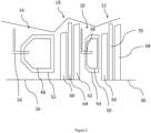
- FIG 2 which shows the area A of figure 1 , the first and second combustors 16, 20 and first turbine section 18, 22 are shown in more detail.
- each combustor 16, 20 is relatively conventional, comprising an inner combustor liner 48, 50 surrounded by an outer combustor casing 52, 54.
- Each combustor 16, 20 further comprises a respective fuel injector 56, 58, which provides fuel such as aviation fuel or diesel, for burning within the gas flow.
- fuel injector 56, 58 which provides fuel such as aviation fuel or diesel, for burning within the gas flow.
- Alternative combustor types may also be utilised, such as reverse flow combustors, lean burn stages combustors, and Rich-Quench-Lean (RQL) combustors.
- Other fuel types may also be used, such as natural gas.
- Each turbine section 18, 22 comprises one or more turbine stages.
- a turbine stage comprises at least one turbine rotor, and optionally, one or more turbine stators.
- the first turbine section 18 comprises first and second turbine rotors 60, 62, with a turbine stator 64 provided therebetween.
- the turbine rotors 60, 62 (which are conventionally bladed rotors), rotate to provide motive power, while the stators redirect gas flow downstream of each rotor to guide the gas flow to the next rotor. Consequently, the first turbine section 18 in this example has two turbine stages.
- the second turbine section 22 has two turbine stages, comprising two turbine rotors 66, 68 and a turbine stator 70 therebetween.
- the first turbine section 18 is provided as part of a first spool, coupled to the first shaft 26, while the second turbine section 22 is provided as part of a second spool, coupled to the second shaft 30.
- the number of turbine stages is selected to provide the desired turbine pressure ratio at the desired shaft rotational speed for the maximum gas flow, utilising the minimum number of stages, as will be understood by the skilled person.
- the pressure ratio of a turbine or turbine section can be found by dividing the pressure at the inlet of the turbine (i.e. upstream of the first turbine stage of the turbine or turbine section) by the pressure at the outlet of the turbine (i.e. downstream of the final turbine stage of the turbine or turbine section).
- power density of the full system can be maximised by providing a first turbine section having a pressure ratio of between 2 and 5. This can typically be provided by a two stage turbine section. In some cases, an optimum power density can be provided by providing a first turbine section having a pressure ratio of between 3.5 and 4.75. This relationship appears to hold for a wide range of turbine entry temperatures and overall pressure ratios. Consequently, where power density (i.e. weight and / or size of the engine is the most important factor in the engine design), then turbines having the above properties should be selected.
- thermal efficiency can be maximised by providing a first turbine section having a pressure ratio of between 1 and 2. This can typically be provided by a single stage turbine section. In some cases, optimum energy efficiency can be provided by providing a first turbine section having a pressure ratio of approximately 1.5. Again, this relationship appears to hold for a wide range of turbine entry temperatures and overall pressure ratios. Consequently, where power density (i.e. weight and / or size of the engine) is the most important factor in the engine design, then turbines having the above properties should be selected.
- OPR Overall Pressure Ratio
- This can be determined by measuring the total pressure at the air inlet 12, by the total pressure at the outlet of the compressor 14 when the engine is operated at full power.
- the inventors have found that, in general, higher overall pressure ratios of the first gas turbine engine 11 result in higher overall system efficiency.
- the overall pressure ratio of the first gas turbine engine 11 is between 30:1 and 60:1.
- the relatively high exhaust temperatures, even at high OPRs, due to the second combustor 20 results in a highly efficient second gas turbine engine, and so a highly efficient cycle overall.
- OPR of the second gas turbine engine affects overall system efficiency.
- the OPR of the second gas turbine engine can be found by dividing the total pressure at the air inlet, by total pressure at the compressor 36 outlet. It has been found that relatively low OPRs of between 3 and 8 provide the greatest overall system efficiency. In many cases, an optimum cycle efficiency is attained from a second gas turbine engine having an OPR of between 4 and 6. Again, this holds over a relatively wide range of turbine entry temperatures and first gas turbine engine OPRs.
- TET Turbine Entry Temperature
- the TET can be determined by measuring the total temperature of the gasses entering the inlet of the first turbine section 18 at a maximum engine power condition. It has been found that, in general, in the cycle of the present disclosure, overall efficiency increases as TET increases. Typically, TET is between 1400 Kelvin and 1800 Kelvin, though higher temperatures may be utilised. This is again in contrast with conventional bottoming cycle engines, in which efficiency typically does not increase with increasing turbine entry temperature.
- the turbine entry temperature (TET) of the second turbine section 22 also affects thermal efficiency. Again, efficiency typically increases with increasing TET, though it may be desirable to set the TET of the second turbine section 22 at a lower value than the first turbine section 18, to minimise cooling losses.
- FIG 3 shows a second combined cycle heat engine 110, which differs from the first heat engine 10 in a number of ways. It will be appreciated that whilst this embodiment does not comprise one or more intercooler in the first air compressor as set out in the introduction and claims, the following description of the second combined cycle heat engine 110 sets out the characteristics of features that are common to both it and the fourth combined cycle heat engine 310 of Figure 5 .
- the engine 110 comprises first and second Brayton cycle gas turbine engines, 111, 132, each having a respective principal and rotational axis.
- the first gas turbine engine 111 comprises, in axial flow series, an air intake 112, a first air compressor 114a, a second air compressor 114b, a first combustor 116, a turbine comprising a first turbine section 118, a second combustor 120, a second turbine section 122 of the turbine, and an exhaust nozzle 124.
- the first turbine section 118 and first compressor 114a are coupled together by a core shaft 126, such that the first turbine section 118 drives the first compressor 114a.
- the second turbine section 122 is coupled to the second compressor 114b and load such as an electrical generator 128 by a power shaft 130. Consequently, the shafts 130, 126, and so the turbines 118, 122 turn independently of one another.
- the first turbine section 118 is provided as part of a first turbine spool
- the second turbine section 122 is provided as part of a second turbine spool, since they rotate independently of one another.
- a second gas turbine engine 132 is also provided, which is similar to the engine 32.
- the second gas turbine engine comprises, in fluid flow series, an air inlet 134, a first air compressor 136a, an intercooler 172, a second air compressor 136b, a cold side of a recuperating heat exchanger 138, a turbine 140, and a nozzle 142.
- the intercooler 172 is a further heat exchanger arranged to cool high temperature air downstream of the first compressor 136a by exchanging heat with ambient air, prior to delivering the cooled air to the second compressor 136b.
- the intercooler 172 is a further heat exchanger arranged to cool high temperature air downstream of the first compressor 136a by exchanging heat with ambient air, prior to delivering the cooled air to the second compressor 136b.
- FIG. 4 shows a third combined cycle heat engine 210, which differs from the first and second heat engines 10, 110 in a number of ways. It will be appreciated that whilst this embodiment does not comprise one or more intercooler in the first air compressor as set out in the introduction and claims, the following description of the third combined cycle heat engine 210 sets out the characteristics of features that are common to both it and the fourth combined cycle heat engine 310 of Figure 5 .
- the engine 210 comprises first and second Brayton cycle gas turbine engines, 211, 232, each having a respective principal and rotational axis.
- the first gas turbine engine 211 comprises, in axial flow series, an air intake 212, an air compressor 214, a first combustor 216, a turbine comprising a first turbine section 218, a second combustor 220, a second turbine section 222 of the turbine, and an exhaust nozzle 224.
- each of the first turbine section 218, second turbine section 222 and compressor 214 are coupled together by a core shaft 226, such that both the first and second turbine sections 218, 222 drive the compressor 214.
- the shaft 226 is also coupled to a load such as an electrical generator 228. Consequently, only a single shaft 226 is provided, such that the first and second turbine sections 218, 222 are provided as part of the same spool.
- a second gas turbine engine 232 is also provided, which is similar to the engines 32, 132.
- the second gas turbine engine comprises, in fluid flow series, an air inlet 234, a first air compressor 236a, an intercooler 272, a second air compressor 236b, a cold side of a recuperating heat exchanger 238, a third combustor 274, a turbine 240, and a nozzle 242.
- the third combustor 274 is configured to provide additional fuel to the second airflow, downstream of the heat exchanger 238 and upstream of the turbine 240, to provide further heat addition to the second gas turbine engine 232 air flow.
- additional work can be extracted from the second gas turbine engine 232.
- the turbine entry temperature is raised, thereby increasing the efficiency of the second gas turbine engine 232, and so increasing the efficiency of the heat engine as a whole. In studies, it has been estimated that overall thermal efficiencies as great as 60% can be realistically achieved with such cycles.
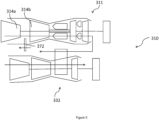
- Figure 5 shows a fourth combined cycle heat engine 311.
- the engine is in many ways similar to the engine 111 of figure 3 , and so only differences relative to that engine will be described in detail.
- the combined cycle heat engine again comprises first and second gas turbine engines 311, 332, which operate in a similar manner to the engines 11, 32, 111, 132 and 211, 232.
- the engine 311 differs to the engines 11, 111, 211 in that an intercooler 372 is provided between compressor stages of the first gas turbine engine 311.
- the intercooler 372 is provided between low and high pressure compressors 314a, 314b, and operates in a similar manner to the intercooler 172, 272, in that it cools compressor air prior to further compression, by exchanging heat with a lower temperature fluid, such as lower temperature air, water or some other medium.
- the second gas turbine engine 332 could also be provided with an intercooler similar to the intercoolers 172, 272, though in this example the intercooler of the second gas turbine engine 332 is omitted.
- intercoolers can be used to reduce the temperature of compressed air prior to further compression by a downstream compressor. This reduces the work required to compress the air, and so allows for a higher efficiency. This also increases the amount of heat that can be added by the combustor without exceeding the temperature limits of the downstream turbines, and so increases power density.
- the turbines due to the lower work required for compression, less expansion is required by the turbines to provide the required work, and so temperatures downstream of the turbine are increased.
- this increased heat rejection by the turbine represents enthalpy which is not used in the thermodynamic cycle of the engine, and so overall thermodynamic efficiency is reduced in some cases.
- T C represents the outlet temperature of the cycle
- T H represents the inlet temperature of the cycle. Consequently, by adding an intercooler 372 to the first gas turbine engine 111, T C of the first cycle is increased, thereby reducing efficiency of that cycle. However, T H of the second cycle is then increased by this same amount, thereby maintaining high efficiency for the second engine 332, and so maintaining overall system thermal efficiency. Consequently, this architecture allows for an increase in power density, without a corresponding reduction in thermal efficiency.
- gas turbine engines to which the present disclosure may be applied may have alternative configurations.
- such engines may have an alternative number of interconnecting shafts (e.g. two) and/or an alternative number of compressors and/or turbines.
- the engine may comprise a gearbox provided in the drive train from a turbine to a compressor and/or fan.
- the number or arrangement of shafts could be changed, so that the second combustor could be located between different turbine sections of the same spool, or of different spools depending on requirements.
- the second combustor could be located between any two stages.
Landscapes
- Engineering & Computer Science (AREA)
- Chemical & Material Sciences (AREA)
- Combustion & Propulsion (AREA)
- Mechanical Engineering (AREA)
- General Engineering & Computer Science (AREA)
- Engine Equipment That Uses Special Cycles (AREA)
Description
- The present disclosure concerns a combined cycle gas turbine engine.
- Combined cycle gas turbine engines are known, and are typically used to increase the thermal efficiency of heat engines relative to simple cycle gas turbine engines.
- In a combined cycle gas turbine engine, waste exhaust heat from a gas turbine engine is used to drive a second heat engine to produce additional net power, without increasing fuel burn.
- One such cycle is known as an "Air Bottoming Cycle" (ABC). Air bottoming cycles incorporate a further Brayton cycle gas turbine engine as the second heat engine. Typically, the second engine comprises a compressor, a heat exchanger, and a turbine in flow series. The compressor draws in air and compresses it. This compressed air is heated by waste exhaust heat from the first gas turbine engine, before being expanded by the turbine. The turbine powers the compressor and a load, to provide net power.
- Such cycles are disclosed for example in "Selection of Gas Turbine Air Bottoming Cycle for Polish compressor stations", by Daniel Czaja, Tadeusz Chmielniak, Sebastian Lepszy, published in the Journal of Power Technologies 93 (2) (2013) 67-77.
-
US 5813215 A discloses a waste heat recovery system for converting waste heat from the effluent of conventional power plants into electricity, the system comprising an open cycle primary stage and a closed cycle secondary stage connected by an exhaust gas heat exchanger. -
US 4147024 A discloses two designs of dual cycle turbine system, where the exhaust heat energy of a high pressure engine section is used to preheat the air furnished to the combustor of a medium pressure second engine section. -
WO 97/04228 A1 -
US 20050056001 A1 discloses a secondary machine connected downstream of an open-cycle gas turboset for the utilization of the waste heat of the exhaust gases. The secondary machine operates in closed cycle with a gaseous process fluid. Intercoolers are included in the compressor of the secondary machine. - According to a first aspect there is provided a combined cycle heat engine comprising: a first gas turbine engine comprising a first air compressor, a first combustion system and a first turbine system; a second gas turbine engine comprising a second air compressor and a second turbine system; and a heat exchanger configured to transfer heat from an exhaust of the first turbine system to compressed air from the second air compressor; wherein the first combustion system comprises a first combustor provided downstream of the first air compressor and upstream of the first turbine system, and a second combustor downstream of a first turbine section of the first turbine system and upstream of a second turbine section of the first turbine system, and wherein the first air compressor comprises a multi-stage compressor comprising two or more rotor stages, and the first gas turbine engine comprises one or more intercooler configured to reject heat from the first air compressor, between rotor stages.
- Advantageously, by providing a combined cycle gas turbine engine having first and second combustors provided between turbine stages of the first gas turbine engine, greatly increased efficiency can be provided relative to both simple cycle gas turbine engines, and conventional combined cycle gas turbines. Furthermore, by providing an intercooler in the first gas turbine engine rather than or in addition to an intercooler in the second gas turbine engine, increased heat provided by the increased turbine outlet temperature is utilised in the second gas turbine engine. Consequently, the efficiency of the second gas turbine engine is raised due to the increased temperature difference between the inlet temperature and the maximum temperature in the heat exchanger. Further benefits and features of the disclosed system are set out below.
- The first combustor may be provided downstream of the first compressor and upstream of the first turbine rotor of the first turbine system, and the second combustor may be provided downstream of a first turbine rotor of the first turbine system, and upstream of a second turbine rotor of the first turbine system.
- Alternatively, the first turbine system may comprise a first turbine shaft mechanically coupled to a first turbine spool of the first turbine system and the first compressor of the first gas turbine engine, and a second turbine shaft mechanically coupled to a second turbine spool of the first turbine system and an external load.
- The first turbine section may be coupled to the first turbine shaft and the second turbine section may be coupled to the second turbine shaft.
- The first air compressor may comprise a low pressure compressor provided upstream of a high pressure compressor. The first turbine shaft may be mechanically coupled to the high pressure compressor and the second turbine shaft may be mechanically coupled to the low pressure compressor.
- The second air compressor may comprise a multi-stage compressor, comprising two or more rotor stages. The second gas turbine engine may comprise one or more intercoolers, configured to reject heat from the second air compressor, between rotor stages. Advantageously, compressor work is decreased, while the temperature rise in the heat exchanger is increased, thereby increasing thermal efficiency of the second gas turbine engine.
- The second gas turbine engine may comprise a second combustion system provided downstream of the heat exchanger, and upstream of the second turbine system.
- The second gas turbine engine may comprise an overall pressure ratio of between 4 and 15, and may comprise an overall pressure ratio of between 5 and 10. It has been found that the highest overall thermal efficiency of the system is achieved at overall pressure ratios of the second gas turbine of these values.
- A pressure ratio of the first turbine section of the first turbine system may be between 2 and 5, and may be between 3.5 and 4.75. It has been found that a turbine having a pressure ratio of these values prior to the second combustor has been found to result in high exhaust temperatures of the first gas turbine, which results in a relatively high specific work, and so high overall power density.
- A pressure ratio of the first turbine section of the first turbine system may be between 1 and 2, and may be approximately 1.5. It has been found that a turbine having an expansion ratio of these values prior to the second combustor has been found to result in high overall energy efficiency.
- Embodiments will now be described by way of example only, with reference to the Figures, in which:
-
Figure 1 is a schematic view of a first combined cycle heat engine; -
Figure 2 is a schematic view of the region A of the first gas turbine engine of the combined cycle heat engine offigure 1 ; -
Figure 3 is a schematic view of a second combined cycle heat engine; -
Figure 4 is a schematic view of a third combined cycle heat engine; and -
Figure 5 is a schematic view of a fourth combined cycle heat engine. - With reference to
Figure 1 , a first combined cycle heat engine is generally indicated at 10. It will be appreciated that whilst this embodiment does not comprise one or more intercooler in the first air compressor as set out in the introduction and claims, the following description of the first combinedcycle heat engine 10 sets out the characteristics of features that are common to both it and the fourth combinedcycle heat engine 310 ofFigure 5 . - The combined
cycle heat engine 10 comprises first and second Brayton cycle gas turbine engines, 11, 32, each having a respective principal and rotational axis. The firstgas turbine engine 11 comprises, in axial flow series, anair intake 12, afirst air compressor 14, afirst combustor 16 of a first combustion system, a first turbine system comprising afirst turbine section 18, asecond combustor 20 of the first combustion system, asecond turbine section 22 of the first turbine system, and anexhaust nozzle 24. - In operation, air entering the
intake 12 is directed to thefirst air compressor 14, which compresses the air flow directed into it before delivering that air to thefirst combustor 16 where it is mixed with fuel and the mixture combusted. The resultant hot combustion products then expand through, and thereby drive thefirst turbine section 18, before being directed to thesecond combustor 20. Thesecond combustor 20 adds further fuel to the air flow, where it is combusted to further raise the heat of the combustion products, before directing this gas flow to thesecond turbine section 22. - The
first turbine section 18 andcompressor 14 are coupled together by acore shaft 26, such that thefirst turbine section 18 drives thecompressor 14. Thesecond turbine section 22 is coupled to a load such as anelectrical generator 28 by apower shaft 30. Consequently, theshafts turbines - A
heat exchanger 38 is also provided, downstream of thenozzle 24. Theheat exchanger 38 comprises hot and cold sides in thermal contact with one another, and is configured to transfer heat from a first gas flow from theexhaust nozzle 24 of the firstgas turbine engine 11, downstream of the first andsecond turbine sections nozzle 24, through theheat exchanger 38, thereby heating the second gas flow, before being vented to atmosphere. Optionally, further heat exchangers may be provided, such that the exhaust heat can be utilised for further purposes, such as water heating. - The combined
cycle heat engine 10 further comprises a second Brayton cyclegas turbine engine 32. The second gas turbine engine comprises, in fluid flow series, anair inlet 34, asecond air compressor 36, a cold side of theheat exchanger 38, asecond turbine system 40, and anexhaust nozzle 42. - In operation, air entering the
intake 34 of the secondgas turbine engine 32 is directed to thesecond air compressor 36, which compresses the air flow directed into it before delivering that air to the cold side of therecuperator heat exchanger 38, where it is heated by waste heat from the exhaust of the firstgas turbine engine 11. Theheat exchanger 38 adds heat to the air flow (which comprises the second air flow of the heat exchanger 38), to raise the temperature of the air flow, before directing this gas flow to theturbine 40. This airflow drives theturbine 40, before being vented to atmosphere. It will be understood that the airflows through the heat exchanger are kept separate, though heat is exchanged between them. Again, further heat exchangers may be provided to utilise this high temperature air. Alternatively, the high temperature air may be utilised for space heating, since the air contains no combustion products. - The
turbine 40 andcompressor 36 are coupled together by acore shaft 44, such that theturbine 40 drives thecompressor 36. Theshaft 44 is also coupled to a load such as anelectrical generator 46, such that the second gas turbine provides net external power to a load. - It has been found that the above described arrangement can provide for a very high overall thermal efficiency combined cycle heat engine. In studies, the engine has been found to have an overall thermal efficiency of up to 55%, while providing a highly compact, power dense arrangement. Since the combined cycle engine operates on air as the working fluid for both the first and second Brayton cycle gas turbine engines, no additional working fluid, such as distilled water, is required, making the system suitable for use on ships. The
loads - Referring now to
figure 2 , which shows the area A offigure 1 , the first andsecond combustors first turbine section - As can be seen, each combustor 16, 20 is relatively conventional, comprising an
inner combustor liner outer combustor casing combustor respective fuel injector - Each
turbine section first turbine section 18 comprises first andsecond turbine rotors turbine stator 64 provided therebetween. In use, theturbine rotors 60, 62 (which are conventionally bladed rotors), rotate to provide motive power, while the stators redirect gas flow downstream of each rotor to guide the gas flow to the next rotor. Consequently, thefirst turbine section 18 in this example has two turbine stages. Similarly, thesecond turbine section 22 has two turbine stages, comprising twoturbine rotors turbine stator 70 therebetween. As can be seen, in this case, thefirst turbine section 18 is provided as part of a first spool, coupled to thefirst shaft 26, while thesecond turbine section 22 is provided as part of a second spool, coupled to thesecond shaft 30. - The number of turbine stages is selected to provide the desired turbine pressure ratio at the desired shaft rotational speed for the maximum gas flow, utilising the minimum number of stages, as will be understood by the skilled person.
- In studies, the inventors have found that particular turbine pressure ratios of the first turbine section provide particular advantages. The pressure ratio of a turbine or turbine section can be found by dividing the pressure at the inlet of the turbine (i.e. upstream of the first turbine stage of the turbine or turbine section) by the pressure at the outlet of the turbine (i.e. downstream of the final turbine stage of the turbine or turbine section).
- It has been found that power density of the full system can be maximised by providing a first turbine section having a pressure ratio of between 2 and 5. This can typically be provided by a two stage turbine section. In some cases, an optimum power density can be provided by providing a first turbine section having a pressure ratio of between 3.5 and 4.75. This relationship appears to hold for a wide range of turbine entry temperatures and overall pressure ratios. Consequently, where power density (i.e. weight and / or size of the engine is the most important factor in the engine design), then turbines having the above properties should be selected.
- On the other hand, thermal efficiency (and so fuel economy) can be maximised by providing a first turbine section having a pressure ratio of between 1 and 2. This can typically be provided by a single stage turbine section. In some cases, optimum energy efficiency can be provided by providing a first turbine section having a pressure ratio of approximately 1.5. Again, this relationship appears to hold for a wide range of turbine entry temperatures and overall pressure ratios. Consequently, where power density (i.e. weight and / or size of the engine) is the most important factor in the engine design, then turbines having the above properties should be selected.
- In order to optimise the overall cycle further, additional parameters can be selected.
- One parameter that affects overall system efficiency is Overall Pressure Ratio (OPR) of the first
gas turbine engine 11. This can be determined by measuring the total pressure at theair inlet 12, by the total pressure at the outlet of thecompressor 14 when the engine is operated at full power. The inventors have found that, in general, higher overall pressure ratios of the firstgas turbine engine 11 result in higher overall system efficiency. Typically, the overall pressure ratio of the firstgas turbine engine 11 is between 30:1 and 60:1. This contrasts with conventional bottoming cycle systems, in which higher overall pressure ratios does not correlate with increased overall system efficiency, since such systems result in relatively low exhaust temperatures for the bottoming cycle engine, which results in low efficiency for that engine. In conjunction with less than perfect component efficiencies, this typically results in cycle efficiencies peaking at lower overall pressure ratios. On the other hand, in the system presently disclosed, the relatively high exhaust temperatures, even at high OPRs, due to thesecond combustor 20, results in a highly efficient second gas turbine engine, and so a highly efficient cycle overall. - Similarly, OPR of the second gas turbine engine affects overall system efficiency. Again, the OPR of the second gas turbine engine can be found by dividing the total pressure at the air inlet, by total pressure at the
compressor 36 outlet. It has been found that relatively low OPRs of between 3 and 8 provide the greatest overall system efficiency. In many cases, an optimum cycle efficiency is attained from a second gas turbine engine having an OPR of between 4 and 6. Again, this holds over a relatively wide range of turbine entry temperatures and first gas turbine engine OPRs. - A further parameter that affects efficiency is the Turbine Entry Temperature (TET) of the
first turbine section 18. The TET can be determined by measuring the total temperature of the gasses entering the inlet of thefirst turbine section 18 at a maximum engine power condition. It has been found that, in general, in the cycle of the present disclosure, overall efficiency increases as TET increases. Typically, TET is between 1400 Kelvin and 1800 Kelvin, though higher temperatures may be utilised. This is again in contrast with conventional bottoming cycle engines, in which efficiency typically does not increase with increasing turbine entry temperature. - The turbine entry temperature (TET) of the
second turbine section 22 also affects thermal efficiency. Again, efficiency typically increases with increasing TET, though it may be desirable to set the TET of thesecond turbine section 22 at a lower value than thefirst turbine section 18, to minimise cooling losses. -
Figure 3 shows a second combinedcycle heat engine 110, which differs from thefirst heat engine 10 in a number of ways. It will be appreciated that whilst this embodiment does not comprise one or more intercooler in the first air compressor as set out in the introduction and claims, the following description of the second combinedcycle heat engine 110 sets out the characteristics of features that are common to both it and the fourth combinedcycle heat engine 310 ofFigure 5 . - In this example, the
engine 110 comprises first and second Brayton cycle gas turbine engines, 111, 132, each having a respective principal and rotational axis. The firstgas turbine engine 111 comprises, in axial flow series, anair intake 112, afirst air compressor 114a, asecond air compressor 114b, afirst combustor 116, a turbine comprising afirst turbine section 118, asecond combustor 120, asecond turbine section 122 of the turbine, and anexhaust nozzle 124. - Air flows through the
engine 110 in a similar manner to theengine 10, as shown by the arrows. In this embodiment, thefirst turbine section 118 andfirst compressor 114a are coupled together by acore shaft 126, such that thefirst turbine section 118 drives thefirst compressor 114a. Thesecond turbine section 122 is coupled to thesecond compressor 114b and load such as anelectrical generator 128 by apower shaft 130. Consequently, theshafts turbines first turbine section 118 is provided as part of a first turbine spool, and thesecond turbine section 122 is provided as part of a second turbine spool, since they rotate independently of one another. - A second
gas turbine engine 132 is also provided, which is similar to theengine 32. The second gas turbine engine comprises, in fluid flow series, anair inlet 134, afirst air compressor 136a, anintercooler 172, asecond air compressor 136b, a cold side of a recuperatingheat exchanger 138, aturbine 140, and anozzle 142. - Again, air flows through the second
gas turbine engine 132 in a similar manner to theengine 32. However, this is slightly modified by the addition of theintercooler 172. Theintercooler 172 is a further heat exchanger arranged to cool high temperature air downstream of thefirst compressor 136a by exchanging heat with ambient air, prior to delivering the cooled air to thesecond compressor 136b. By cooling the air between compression stages, several effects are achieved. Firstly, the work required to compress the air is increased, thereby increasing the pressure ratio of the engine for a given turbine power. However, this reduces the turbine entry temperature, by reducing the heat added during the cycle, which reduces the efficiency of the engine. Since the second gas turbine engine runs of heat from the first gas turbine engine however, the overall cycle efficiency is increased, since waste heat is utilised, rather than heat from burning fuel. -
Figure 4 shows a third combinedcycle heat engine 210, which differs from the first andsecond heat engines cycle heat engine 210 sets out the characteristics of features that are common to both it and the fourth combinedcycle heat engine 310 ofFigure 5 . - In this example, the
engine 210 comprises first and second Brayton cycle gas turbine engines, 211, 232, each having a respective principal and rotational axis. The firstgas turbine engine 211 comprises, in axial flow series, anair intake 212, anair compressor 214, afirst combustor 216, a turbine comprising afirst turbine section 218, asecond combustor 220, asecond turbine section 222 of the turbine, and anexhaust nozzle 224. - Air flows through the
engine 210 in a similar manner to theengines first turbine section 218,second turbine section 222 andcompressor 214 are coupled together by acore shaft 226, such that both the first andsecond turbine sections compressor 214. Theshaft 226 is also coupled to a load such as anelectrical generator 228. Consequently, only asingle shaft 226 is provided, such that the first andsecond turbine sections - A second
gas turbine engine 232 is also provided, which is similar to theengines air inlet 234, afirst air compressor 236a, anintercooler 272, asecond air compressor 236b, a cold side of a recuperatingheat exchanger 238, athird combustor 274, aturbine 240, and anozzle 242. - Again, air flows through the second
gas turbine engine 132 in a similar manner to theengine 132. However, this is slightly modified by the addition of thethird combustor 274. Thethird combustor 274 is configured to provide additional fuel to the second airflow, downstream of theheat exchanger 238 and upstream of theturbine 240, to provide further heat addition to the secondgas turbine engine 232 air flow. In view of this further heat addition, additional work can be extracted from the secondgas turbine engine 232. Furthermore, the turbine entry temperature is raised, thereby increasing the efficiency of the secondgas turbine engine 232, and so increasing the efficiency of the heat engine as a whole. In studies, it has been estimated that overall thermal efficiencies as great as 60% can be realistically achieved with such cycles. -
Figure 5 shows a fourth combinedcycle heat engine 311. The engine is in many ways similar to theengine 111 offigure 3 , and so only differences relative to that engine will be described in detail. - The combined cycle heat engine again comprises first and second
gas turbine engines engines engine 311 differs to theengines intercooler 372 is provided between compressor stages of the firstgas turbine engine 311. In this embodiment, theintercooler 372 is provided between low andhigh pressure compressors intercooler - The second
gas turbine engine 332 could also be provided with an intercooler similar to theintercoolers gas turbine engine 332 is omitted. - By providing an intercooler in the first
gas turbine engine 311 rather than or in addition to an intercooler in the secondgas turbine engine 332, various advantages can be realised. - Conventionally, intercoolers can be used to reduce the temperature of compressed air prior to further compression by a downstream compressor. This reduces the work required to compress the air, and so allows for a higher efficiency. This also increases the amount of heat that can be added by the combustor without exceeding the temperature limits of the downstream turbines, and so increases power density. However, due to the lower work required for compression, less expansion is required by the turbines to provide the required work, and so temperatures downstream of the turbine are increased. In combination with the heat rejected by the intercooler, this increased heat rejection by the turbine represents enthalpy which is not used in the thermodynamic cycle of the engine, and so overall thermodynamic efficiency is reduced in some cases.
- However, in the present case, this increased heat provided by the increased turbine outlet temperature is utilised in the second
gas turbine engine 332. Consequently, the efficiency of the second gas turbine engine is raised due to the increased temperature difference between the inlet temperature and the maximum temperature in the heat exchanger, since thermal efficiency is related to this temperature difference by the well-known Carnot efficiency equation:
- Where η represents efficiency, TC represents the outlet temperature of the cycle, and TH represents the inlet temperature of the cycle. Consequently, by adding an
intercooler 372 to the firstgas turbine engine 111, TC of the first cycle is increased, thereby reducing efficiency of that cycle. However, TH of the second cycle is then increased by this same amount, thereby maintaining high efficiency for thesecond engine 332, and so maintaining overall system thermal efficiency. Consequently, this architecture allows for an increase in power density, without a corresponding reduction in thermal efficiency. - Other gas turbine engines to which the present disclosure may be applied may have alternative configurations. By way of example such engines may have an alternative number of interconnecting shafts (e.g. two) and/or an alternative number of compressors and/or turbines. Further the engine may comprise a gearbox provided in the drive train from a turbine to a compressor and/or fan.
- It will be understood that the invention is not limited to the embodiments above-described and various modifications and improvements can be made without departing from the concepts described herein within the scope of the following claims.
- For example, the number or arrangement of shafts could be changed, so that the second combustor could be located between different turbine sections of the same spool, or of different spools depending on requirements. Similarly, where multi-stage turbine spools are provided, the second combustor could be located between any two stages.
Claims (14)
- A combined cycle heat engine (310) comprising:a first gas turbine engine (311) comprising a first air compressor (314a, 314b), a first combustion system (116, 120) and a first turbine system (118, 122);a second gas turbine engine (332) comprising a second air compressor (136a, 136b) and a second turbine system (140); anda heat exchanger (138) configured to transfer heat from an exhaust of the first turbine system (118, 122) to compressed air from the second air compressor (136a, 136b);wherein the first combustion system comprises a first combustor (116) provided downstream of the first air compressor (314a, 314b) and upstream of the first turbine system (118, 122), and a second combustor (120) downstream of a first turbine section (118) of the first turbine system and upstream of a second turbine section (122) of the first turbine system;characterised in that the first air compressor (314a, 314b) comprises a multi-stage compressor (314a, 314b) comprising two or more rotor stages, and the first gas turbine engine (311) comprises one or more intercoolers (372) configured to reject heat from the first air compressor (314a, 314b), between rotor stages.
- A combined cycle heat engine according to claim 1, wherein first combustor (116) is provided downstream of the first compressor (314a, 314b) and upstream of a first turbine rotor (60) of the first turbine system (118, 122), and the second combustor (120) is provided downstream of a first turbine rotor (60) of the first turbine system, and upstream of a second turbine rotor (66) of the first turbine system (118, 122).
- A combined cycle heat engine according to claim 1 or claim 2, wherein the first turbine system (118, 122) comprises a first turbine shaft (126) mechanically coupled to a first turbine spool (118) of the first turbine system (118, 122) and the first compressor (314a) of the first gas turbine engine (311), and a second turbine shaft (130) mechanically coupled to a second turbine spool (122) of the first turbine system (118, 122) and an external load (128).
- A combined cycle heat engine according to claim 3, wherein the first turbine section (118) is coupled to the first turbine shaft (126) and the second turbine section (122) is coupled to the second turbine shaft (130).
- A combined cycle heat engine according to any preceding claim, wherein the first air compressor comprises a low pressure compressor (314a) provided upstream of a high pressure compressor (314b).
- A combined cycle heat engine according to claim 5 when dependent on claim 3, wherein the first turbine shaft (126) is mechanically coupled to the high pressure compressor (314b) and the second turbine shaft (130) is mechanically coupled to the low pressure compressor (314a).
- A combined cycle heat engine according to any preceding claim, wherein the second air compressor (136a, 136b) comprises a multi-stage compressor (136a, 136b) comprising two or more rotor stages, and the second gas turbine engine (332) comprises one or more intercooler (172, 272) configured to reject heat from the second air compressor (136a, 136b), between rotor stages.
- A combined cycle heat engine according to any preceding claim, wherein the second gas turbine engine (232) comprises a second combustion system (274) provided downstream of the heat exchanger (238), and upstream of the second turbine system (240).
- A combined cycle heat engine according to any preceding claim, wherein the second gas turbine engine (332) comprises an overall pressure ratio of between 4 and 15.
- A combined cycle heat engine according to claim 9, wherein the second gas turbine engine (332) comprises an overall pressure ratio of between 5 and 10.
- A combined cycle heat engine according to any preceding claim, wherein a pressure ratio of the first turbine section (18) of the first turbine system (18, 20) is between 2 and 5.
- A combined cycle heat engine according to claim 11, wherein the pressure ratio of the first turbine section (18) of the first turbine system (18, 20) is between 3.5 and 4.75.
- A combined cycle heat engine according to claim 12, wherein the pressure ratio of the first turbine section (18) of the first turbine system (18, 20) is between 1 and 2.
- A combined cycle heat engine according to claim 13, wherein the pressure ratio of the first turbine section (18) of the first turbine system (18, 20) is approximately 1.5.
Applications Claiming Priority (2)
| Application Number | Priority Date | Filing Date | Title |
|---|---|---|---|
| GBGB1819565.1A GB201819565D0 (en) | 2018-11-30 | 2018-11-30 | Gas turbine engine |
| GBGB1819564.4A GB201819564D0 (en) | 2018-11-30 | 2018-11-30 | Gas turbine engine |
Publications (2)
| Publication Number | Publication Date |
|---|---|
| EP3660294A1 EP3660294A1 (en) | 2020-06-03 |
| EP3660294B1 true EP3660294B1 (en) | 2024-07-31 |
Family
ID=68424646
Family Applications (2)
| Application Number | Title | Priority Date | Filing Date |
|---|---|---|---|
| EP19206261.0A Active EP3660294B1 (en) | 2018-11-30 | 2019-10-30 | Gas turbine engine |
| EP19206263.6A Withdrawn EP3660292A1 (en) | 2018-11-30 | 2019-10-30 | Gas turbine engine |
Family Applications After (1)
| Application Number | Title | Priority Date | Filing Date |
|---|---|---|---|
| EP19206263.6A Withdrawn EP3660292A1 (en) | 2018-11-30 | 2019-10-30 | Gas turbine engine |
Country Status (3)
| Country | Link |
|---|---|
| US (2) | US11391209B2 (en) |
| EP (2) | EP3660294B1 (en) |
| CN (2) | CN111255568A (en) |
Families Citing this family (8)
| Publication number | Priority date | Publication date | Assignee | Title |
|---|---|---|---|---|
| EP3708495B1 (en) * | 2019-03-11 | 2021-11-17 | Airbus SAS | Aircraft propulsion system including a heat exchanger system |
| CN111911244B (en) * | 2020-06-29 | 2022-01-18 | 东方电气集团东方汽轮机有限公司 | Multi-cylinder air turbine unit |
| EP3961001A1 (en) * | 2020-08-25 | 2022-03-02 | General Electric Company | Gas turbine alignment assembly and method |
| FR3120251B1 (en) * | 2021-02-26 | 2025-02-28 | Psa Automobiles Sa | TURBOMACHINE DEVICE WITH GENERATOR POWER SYSTEM AND VEHICLE COMPRISING SUCH A DEVICE |
| JP7535966B2 (en) * | 2021-03-17 | 2024-08-19 | 本田技研工業株式会社 | Gas Turbine Generator |
| CN113309633B (en) * | 2021-05-27 | 2022-05-20 | 中国科学院工程热物理研究所 | An engine with a combined layout of variable cycle and continuously variable drive fans |
| US12589882B2 (en) | 2022-07-22 | 2026-03-31 | Rtx Corporation | Shared cryogenic bottoming cycle |
| WO2024258884A2 (en) * | 2023-06-11 | 2024-12-19 | Claudio Filippone | Carbon-free power conversion system for supplying high-temperature process heat and electricity |
Citations (1)
| Publication number | Priority date | Publication date | Assignee | Title |
|---|---|---|---|---|
| US20050056001A1 (en) * | 2002-03-14 | 2005-03-17 | Frutschi Hans Ulrich | Power generation plant |
Family Cites Families (20)
| Publication number | Priority date | Publication date | Assignee | Title |
|---|---|---|---|---|
| US2814181A (en) * | 1952-11-18 | 1957-11-26 | Air Precheater Corp | Regenerative heat exchangers for paired gas turbines |
| US3791137A (en) * | 1972-05-15 | 1974-02-12 | Secr Defence | Fluidized bed powerplant with helium circuit, indirect heat exchange and compressed air bypass control |
| US4147024A (en) * | 1977-09-15 | 1979-04-03 | Avco Corporation | Dual cycle gas turbine engine system |
| CH632560A5 (en) * | 1978-10-06 | 1982-10-15 | Bbc Brown Boveri & Cie | Gas turbine plant |
| US4813227A (en) * | 1978-10-26 | 1989-03-21 | Rice Ivan G | Preheat gas turbine combined with steam turbine |
| US4571935A (en) * | 1978-10-26 | 1986-02-25 | Rice Ivan G | Process for steam cooling a power turbine |
| US4896499A (en) * | 1978-10-26 | 1990-01-30 | Rice Ivan G | Compression intercooled gas turbine combined cycle |
| US4550562A (en) * | 1981-06-17 | 1985-11-05 | Rice Ivan G | Method of steam cooling a gas generator |
| US4569195A (en) * | 1984-04-27 | 1986-02-11 | General Electric Company | Fluid injection gas turbine engine and method for operating |
| US5813215A (en) * | 1995-02-21 | 1998-09-29 | Weisser; Arthur M. | Combined cycle waste heat recovery system |
| NO300286B1 (en) * | 1995-07-17 | 1997-05-05 | Kvaerner Energy As | Process for influencing the overall efficiency of a thermodynamic conversion system and a thermodynamic conversion system |
| US5937633A (en) * | 1996-05-31 | 1999-08-17 | Wang; Lin-Shu | High-pressure intercooled gas turbine |
| GB2373299B (en) * | 2001-03-12 | 2004-10-27 | Alstom Power Nv | Re-fired gas turbine engine |
| US20090301054A1 (en) * | 2008-06-04 | 2009-12-10 | Simpson Stanley F | Turbine system having exhaust gas recirculation and reheat |
| US8164208B2 (en) * | 2009-04-15 | 2012-04-24 | General Electric Company | Systems involving multi-spool generators and variable speed electrical generators |
| US20120000204A1 (en) * | 2010-07-02 | 2012-01-05 | Icr Turbine Engine Corporation | Multi-spool intercooled recuperated gas turbine |
| US20120042656A1 (en) * | 2010-08-20 | 2012-02-23 | Icr Turbine Engine Corporation | Gas turbine engine with exhaust rankine cycle |
| US9624829B2 (en) * | 2013-03-05 | 2017-04-18 | Industrial Turbine Company (Uk) Limited | Cogen heat load matching through reheat and capacity match |
| US20160047307A1 (en) * | 2014-08-15 | 2016-02-18 | General Electric Company | Power train architectures with low-loss lubricant bearings and low-density materials |
| GB201518929D0 (en) * | 2015-10-27 | 2015-12-09 | Rolls Royce Plc | Gas turbine engine |
-
2019
- 2019-10-30 EP EP19206261.0A patent/EP3660294B1/en active Active
- 2019-10-30 EP EP19206263.6A patent/EP3660292A1/en not_active Withdrawn
- 2019-11-25 US US16/694,047 patent/US11391209B2/en active Active
- 2019-11-25 US US16/694,134 patent/US11187150B2/en active Active
- 2019-11-27 CN CN201911189320.5A patent/CN111255568A/en active Pending
- 2019-11-27 CN CN201911189319.2A patent/CN111255567A/en active Pending
Patent Citations (1)
| Publication number | Priority date | Publication date | Assignee | Title |
|---|---|---|---|---|
| US20050056001A1 (en) * | 2002-03-14 | 2005-03-17 | Frutschi Hans Ulrich | Power generation plant |
Also Published As
| Publication number | Publication date |
|---|---|
| CN111255568A (en) | 2020-06-09 |
| US11391209B2 (en) | 2022-07-19 |
| US11187150B2 (en) | 2021-11-30 |
| EP3660292A1 (en) | 2020-06-03 |
| EP3660294A1 (en) | 2020-06-03 |
| CN111255567A (en) | 2020-06-09 |
| US20200173364A1 (en) | 2020-06-04 |
| US20200173301A1 (en) | 2020-06-04 |
Similar Documents
| Publication | Publication Date | Title |
|---|---|---|
| EP3660294B1 (en) | Gas turbine engine | |
| US11047307B2 (en) | Hybrid expander cycle with intercooling and turbo-generator | |
| JP6739956B2 (en) | Turbine engine with integrated heat recovery and cooling cycle system | |
| US8858161B1 (en) | Multiple staged compressor with last stage airfoil cooling | |
| US6079197A (en) | High temperature compression and reheat gas turbine cycle and related method | |
| US20190359340A1 (en) | Aircraft environmental control system | |
| US6378287B2 (en) | Multi-stage turbomachine and design method | |
| US20130111923A1 (en) | Gas turbine engine component axis configurations | |
| US9388737B2 (en) | Aero boost—gas turbine energy supplementing systems and efficient inlet cooling and heating, and methods of making and using the same | |
| McDonald et al. | Small recuperated ceramic microturbine demonstrator concept | |
| US7240478B2 (en) | Highly supercharged regenerative gas turbine | |
| US8794907B1 (en) | Multiple staged compressor with last stage airfoil cooling | |
| WO2014055717A1 (en) | Aero boost - gas turbine energy supplementing systems and efficient inlet cooling and heating, and methods of making and using the same | |
| US6260349B1 (en) | Multi-stage turbo-machines with specific blade dimension ratios | |
| Hansen et al. | Land Based Gas Turbines for Power Production | |
| Ighodaro et al. | Comparative performance assessment of different gas turbine configurations: A study of a local power station in Nigeria | |
| US8721265B1 (en) | Multiple staged compressor with last stage airfoil cooling | |
| US12104535B2 (en) | Thermal management system for a gas turbine engine | |
| Mohapatra et al. | Parametric analysis of cooled gas turbine cycle with evaporative inlet air cooling | |
| Korakianitis et al. | Investigation of the part-load performance of two 1.12 MW regenerative marine gas turbines | |
| US12092054B1 (en) | Combined Brayton and Stirling cycle power generator | |
| Mills et al. | Intercooled/recuperated shipboard generator drive engine | |
| Foster-Pegg | Turbo-STIG: The Turbocharged Steam Injected Gas Turbine Cycle | |
| Rice | Evaluation of the Compression-Intercooled Reheat-Gas-Turbine-Combined Cycle | |
| Horton et al. | Conceptual design of a solar powered closed-cycle gas turbine electric power generation system |
Legal Events
| Date | Code | Title | Description |
|---|---|---|---|
| PUAI | Public reference made under article 153(3) epc to a published international application that has entered the european phase |
Free format text: ORIGINAL CODE: 0009012 |
|
| STAA | Information on the status of an ep patent application or granted ep patent |
Free format text: STATUS: THE APPLICATION HAS BEEN PUBLISHED |
|
| AK | Designated contracting states |
Kind code of ref document: A1 Designated state(s): AL AT BE BG CH CY CZ DE DK EE ES FI FR GB GR HR HU IE IS IT LI LT LU LV MC MK MT NL NO PL PT RO RS SE SI SK SM TR |
|
| AX | Request for extension of the european patent |
Extension state: BA ME |
|
| STAA | Information on the status of an ep patent application or granted ep patent |
Free format text: STATUS: REQUEST FOR EXAMINATION WAS MADE |
|
| 17P | Request for examination filed |
Effective date: 20201202 |
|
| RBV | Designated contracting states (corrected) |
Designated state(s): AL AT BE BG CH CY CZ DE DK EE ES FI FR GB GR HR HU IE IS IT LI LT LU LV MC MK MT NL NO PL PT RO RS SE SI SK SM TR |
|
| STAA | Information on the status of an ep patent application or granted ep patent |
Free format text: STATUS: EXAMINATION IS IN PROGRESS |
|
| 17Q | First examination report despatched |
Effective date: 20220428 |
|
| GRAP | Despatch of communication of intention to grant a patent |
Free format text: ORIGINAL CODE: EPIDOSNIGR1 |
|
| STAA | Information on the status of an ep patent application or granted ep patent |
Free format text: STATUS: GRANT OF PATENT IS INTENDED |
|
| INTG | Intention to grant announced |
Effective date: 20240326 |
|
| GRAJ | Information related to disapproval of communication of intention to grant by the applicant or resumption of examination proceedings by the epo deleted |
Free format text: ORIGINAL CODE: EPIDOSDIGR1 |
|
| STAA | Information on the status of an ep patent application or granted ep patent |
Free format text: STATUS: EXAMINATION IS IN PROGRESS |
|
| P01 | Opt-out of the competence of the unified patent court (upc) registered |
Effective date: 20240410 |
|
| INTC | Intention to grant announced (deleted) | ||
| GRAP | Despatch of communication of intention to grant a patent |
Free format text: ORIGINAL CODE: EPIDOSNIGR1 |
|
| STAA | Information on the status of an ep patent application or granted ep patent |
Free format text: STATUS: GRANT OF PATENT IS INTENDED |
|
| GRAS | Grant fee paid |
Free format text: ORIGINAL CODE: EPIDOSNIGR3 |
|
| GRAA | (expected) grant |
Free format text: ORIGINAL CODE: 0009210 |
|
| STAA | Information on the status of an ep patent application or granted ep patent |
Free format text: STATUS: THE PATENT HAS BEEN GRANTED |
|
| INTG | Intention to grant announced |
Effective date: 20240618 |
|
| AK | Designated contracting states |
Kind code of ref document: B1 Designated state(s): AL AT BE BG CH CY CZ DE DK EE ES FI FR GB GR HR HU IE IS IT LI LT LU LV MC MK MT NL NO PL PT RO RS SE SI SK SM TR |
|
| REG | Reference to a national code |
Ref country code: CH Ref legal event code: EP Ref country code: GB Ref legal event code: FG4D |
|
| REG | Reference to a national code |
Ref country code: DE Ref legal event code: R096 Ref document number: 602019056034 Country of ref document: DE |
|
| REG | Reference to a national code |
Ref country code: IE Ref legal event code: FG4D |
|
| REG | Reference to a national code |
Ref country code: LT Ref legal event code: MG9D |
|
| REG | Reference to a national code |
Ref country code: NL Ref legal event code: MP Effective date: 20240731 |
|
| PG25 | Lapsed in a contracting state [announced via postgrant information from national office to epo] |
Ref country code: PT Free format text: LAPSE BECAUSE OF FAILURE TO SUBMIT A TRANSLATION OF THE DESCRIPTION OR TO PAY THE FEE WITHIN THE PRESCRIBED TIME-LIMIT Effective date: 20241202 |
|
| REG | Reference to a national code |
Ref country code: AT Ref legal event code: MK05 Ref document number: 1708649 Country of ref document: AT Kind code of ref document: T Effective date: 20240731 |
|
| PG25 | Lapsed in a contracting state [announced via postgrant information from national office to epo] |
Ref country code: PT Free format text: LAPSE BECAUSE OF FAILURE TO SUBMIT A TRANSLATION OF THE DESCRIPTION OR TO PAY THE FEE WITHIN THE PRESCRIBED TIME-LIMIT Effective date: 20241202 |
|
| PG25 | Lapsed in a contracting state [announced via postgrant information from national office to epo] |
Ref country code: NO Free format text: LAPSE BECAUSE OF FAILURE TO SUBMIT A TRANSLATION OF THE DESCRIPTION OR TO PAY THE FEE WITHIN THE PRESCRIBED TIME-LIMIT Effective date: 20241031 |
|
| PG25 | Lapsed in a contracting state [announced via postgrant information from national office to epo] |
Ref country code: NL Free format text: LAPSE BECAUSE OF FAILURE TO SUBMIT A TRANSLATION OF THE DESCRIPTION OR TO PAY THE FEE WITHIN THE PRESCRIBED TIME-LIMIT Effective date: 20240731 Ref country code: FI Free format text: LAPSE BECAUSE OF FAILURE TO SUBMIT A TRANSLATION OF THE DESCRIPTION OR TO PAY THE FEE WITHIN THE PRESCRIBED TIME-LIMIT Effective date: 20240731 Ref country code: GR Free format text: LAPSE BECAUSE OF FAILURE TO SUBMIT A TRANSLATION OF THE DESCRIPTION OR TO PAY THE FEE WITHIN THE PRESCRIBED TIME-LIMIT Effective date: 20241101 Ref country code: PL Free format text: LAPSE BECAUSE OF FAILURE TO SUBMIT A TRANSLATION OF THE DESCRIPTION OR TO PAY THE FEE WITHIN THE PRESCRIBED TIME-LIMIT Effective date: 20240731 |
|
| PG25 | Lapsed in a contracting state [announced via postgrant information from national office to epo] |
Ref country code: BG Free format text: LAPSE BECAUSE OF FAILURE TO SUBMIT A TRANSLATION OF THE DESCRIPTION OR TO PAY THE FEE WITHIN THE PRESCRIBED TIME-LIMIT Effective date: 20240731 |
|
| PG25 | Lapsed in a contracting state [announced via postgrant information from national office to epo] |
Ref country code: LV Free format text: LAPSE BECAUSE OF FAILURE TO SUBMIT A TRANSLATION OF THE DESCRIPTION OR TO PAY THE FEE WITHIN THE PRESCRIBED TIME-LIMIT Effective date: 20240731 |
|
| PG25 | Lapsed in a contracting state [announced via postgrant information from national office to epo] |
Ref country code: AT Free format text: LAPSE BECAUSE OF FAILURE TO SUBMIT A TRANSLATION OF THE DESCRIPTION OR TO PAY THE FEE WITHIN THE PRESCRIBED TIME-LIMIT Effective date: 20240731 Ref country code: IS Free format text: LAPSE BECAUSE OF FAILURE TO SUBMIT A TRANSLATION OF THE DESCRIPTION OR TO PAY THE FEE WITHIN THE PRESCRIBED TIME-LIMIT Effective date: 20241130 |
|
| PG25 | Lapsed in a contracting state [announced via postgrant information from national office to epo] |
Ref country code: HR Free format text: LAPSE BECAUSE OF FAILURE TO SUBMIT A TRANSLATION OF THE DESCRIPTION OR TO PAY THE FEE WITHIN THE PRESCRIBED TIME-LIMIT Effective date: 20240731 |
|
| PG25 | Lapsed in a contracting state [announced via postgrant information from national office to epo] |
Ref country code: ES Free format text: LAPSE BECAUSE OF FAILURE TO SUBMIT A TRANSLATION OF THE DESCRIPTION OR TO PAY THE FEE WITHIN THE PRESCRIBED TIME-LIMIT Effective date: 20240731 Ref country code: RS Free format text: LAPSE BECAUSE OF FAILURE TO SUBMIT A TRANSLATION OF THE DESCRIPTION OR TO PAY THE FEE WITHIN THE PRESCRIBED TIME-LIMIT Effective date: 20241031 |
|
| PG25 | Lapsed in a contracting state [announced via postgrant information from national office to epo] |
Ref country code: RS Free format text: LAPSE BECAUSE OF FAILURE TO SUBMIT A TRANSLATION OF THE DESCRIPTION OR TO PAY THE FEE WITHIN THE PRESCRIBED TIME-LIMIT Effective date: 20241031 Ref country code: PL Free format text: LAPSE BECAUSE OF FAILURE TO SUBMIT A TRANSLATION OF THE DESCRIPTION OR TO PAY THE FEE WITHIN THE PRESCRIBED TIME-LIMIT Effective date: 20240731 Ref country code: NO Free format text: LAPSE BECAUSE OF FAILURE TO SUBMIT A TRANSLATION OF THE DESCRIPTION OR TO PAY THE FEE WITHIN THE PRESCRIBED TIME-LIMIT Effective date: 20241031 Ref country code: NL Free format text: LAPSE BECAUSE OF FAILURE TO SUBMIT A TRANSLATION OF THE DESCRIPTION OR TO PAY THE FEE WITHIN THE PRESCRIBED TIME-LIMIT Effective date: 20240731 Ref country code: LV Free format text: LAPSE BECAUSE OF FAILURE TO SUBMIT A TRANSLATION OF THE DESCRIPTION OR TO PAY THE FEE WITHIN THE PRESCRIBED TIME-LIMIT Effective date: 20240731 Ref country code: IS Free format text: LAPSE BECAUSE OF FAILURE TO SUBMIT A TRANSLATION OF THE DESCRIPTION OR TO PAY THE FEE WITHIN THE PRESCRIBED TIME-LIMIT Effective date: 20241130 Ref country code: HR Free format text: LAPSE BECAUSE OF FAILURE TO SUBMIT A TRANSLATION OF THE DESCRIPTION OR TO PAY THE FEE WITHIN THE PRESCRIBED TIME-LIMIT Effective date: 20240731 Ref country code: GR Free format text: LAPSE BECAUSE OF FAILURE TO SUBMIT A TRANSLATION OF THE DESCRIPTION OR TO PAY THE FEE WITHIN THE PRESCRIBED TIME-LIMIT Effective date: 20241101 Ref country code: FI Free format text: LAPSE BECAUSE OF FAILURE TO SUBMIT A TRANSLATION OF THE DESCRIPTION OR TO PAY THE FEE WITHIN THE PRESCRIBED TIME-LIMIT Effective date: 20240731 Ref country code: ES Free format text: LAPSE BECAUSE OF FAILURE TO SUBMIT A TRANSLATION OF THE DESCRIPTION OR TO PAY THE FEE WITHIN THE PRESCRIBED TIME-LIMIT Effective date: 20240731 Ref country code: BG Free format text: LAPSE BECAUSE OF FAILURE TO SUBMIT A TRANSLATION OF THE DESCRIPTION OR TO PAY THE FEE WITHIN THE PRESCRIBED TIME-LIMIT Effective date: 20240731 Ref country code: AT Free format text: LAPSE BECAUSE OF FAILURE TO SUBMIT A TRANSLATION OF THE DESCRIPTION OR TO PAY THE FEE WITHIN THE PRESCRIBED TIME-LIMIT Effective date: 20240731 |
|
| PG25 | Lapsed in a contracting state [announced via postgrant information from national office to epo] |
Ref country code: RO Free format text: LAPSE BECAUSE OF FAILURE TO SUBMIT A TRANSLATION OF THE DESCRIPTION OR TO PAY THE FEE WITHIN THE PRESCRIBED TIME-LIMIT Effective date: 20240731 Ref country code: SM Free format text: LAPSE BECAUSE OF FAILURE TO SUBMIT A TRANSLATION OF THE DESCRIPTION OR TO PAY THE FEE WITHIN THE PRESCRIBED TIME-LIMIT Effective date: 20240731 Ref country code: DK Free format text: LAPSE BECAUSE OF FAILURE TO SUBMIT A TRANSLATION OF THE DESCRIPTION OR TO PAY THE FEE WITHIN THE PRESCRIBED TIME-LIMIT Effective date: 20240731 |
|
| PG25 | Lapsed in a contracting state [announced via postgrant information from national office to epo] |
Ref country code: EE Free format text: LAPSE BECAUSE OF FAILURE TO SUBMIT A TRANSLATION OF THE DESCRIPTION OR TO PAY THE FEE WITHIN THE PRESCRIBED TIME-LIMIT Effective date: 20240731 |
|
| PG25 | Lapsed in a contracting state [announced via postgrant information from national office to epo] |
Ref country code: CZ Free format text: LAPSE BECAUSE OF FAILURE TO SUBMIT A TRANSLATION OF THE DESCRIPTION OR TO PAY THE FEE WITHIN THE PRESCRIBED TIME-LIMIT Effective date: 20240731 |
|
| PG25 | Lapsed in a contracting state [announced via postgrant information from national office to epo] |
Ref country code: SK Free format text: LAPSE BECAUSE OF FAILURE TO SUBMIT A TRANSLATION OF THE DESCRIPTION OR TO PAY THE FEE WITHIN THE PRESCRIBED TIME-LIMIT Effective date: 20240731 Ref country code: IT Free format text: LAPSE BECAUSE OF FAILURE TO SUBMIT A TRANSLATION OF THE DESCRIPTION OR TO PAY THE FEE WITHIN THE PRESCRIBED TIME-LIMIT Effective date: 20240731 |
|
| REG | Reference to a national code |
Ref country code: DE Ref legal event code: R097 Ref document number: 602019056034 Country of ref document: DE |
|
| REG | Reference to a national code |
Ref country code: CH Ref legal event code: PL |
|
| PLBE | No opposition filed within time limit |
Free format text: ORIGINAL CODE: 0009261 |
|
| STAA | Information on the status of an ep patent application or granted ep patent |
Free format text: STATUS: NO OPPOSITION FILED WITHIN TIME LIMIT |
|
| PG25 | Lapsed in a contracting state [announced via postgrant information from national office to epo] |
Ref country code: MC Free format text: LAPSE BECAUSE OF FAILURE TO SUBMIT A TRANSLATION OF THE DESCRIPTION OR TO PAY THE FEE WITHIN THE PRESCRIBED TIME-LIMIT Effective date: 20240731 |
|
| 26N | No opposition filed |
Effective date: 20250501 |
|
| PG25 | Lapsed in a contracting state [announced via postgrant information from national office to epo] |
Ref country code: LU Free format text: LAPSE BECAUSE OF NON-PAYMENT OF DUE FEES Effective date: 20241030 Ref country code: BE Free format text: LAPSE BECAUSE OF NON-PAYMENT OF DUE FEES Effective date: 20241031 |
|
| PG25 | Lapsed in a contracting state [announced via postgrant information from national office to epo] |
Ref country code: CH Free format text: LAPSE BECAUSE OF NON-PAYMENT OF DUE FEES Effective date: 20241031 |
|
| REG | Reference to a national code |
Ref country code: BE Ref legal event code: MM Effective date: 20241031 |
|
| PG25 | Lapsed in a contracting state [announced via postgrant information from national office to epo] |
Ref country code: SE Free format text: LAPSE BECAUSE OF FAILURE TO SUBMIT A TRANSLATION OF THE DESCRIPTION OR TO PAY THE FEE WITHIN THE PRESCRIBED TIME-LIMIT Effective date: 20240731 |
|
| PG25 | Lapsed in a contracting state [announced via postgrant information from national office to epo] |
Ref country code: IE Free format text: LAPSE BECAUSE OF NON-PAYMENT OF DUE FEES Effective date: 20241030 |
|
| PGFP | Annual fee paid to national office [announced via postgrant information from national office to epo] |
Ref country code: DE Payment date: 20251028 Year of fee payment: 7 |
|
| PGFP | Annual fee paid to national office [announced via postgrant information from national office to epo] |
Ref country code: GB Payment date: 20251023 Year of fee payment: 7 |
|
| PGFP | Annual fee paid to national office [announced via postgrant information from national office to epo] |
Ref country code: FR Payment date: 20251027 Year of fee payment: 7 |
|
| PG25 | Lapsed in a contracting state [announced via postgrant information from national office to epo] |
Ref country code: HU Free format text: LAPSE BECAUSE OF FAILURE TO SUBMIT A TRANSLATION OF THE DESCRIPTION OR TO PAY THE FEE WITHIN THE PRESCRIBED TIME-LIMIT; INVALID AB INITIO Effective date: 20191030 |
|
| PG25 | Lapsed in a contracting state [announced via postgrant information from national office to epo] |
Ref country code: CY Free format text: LAPSE BECAUSE OF FAILURE TO SUBMIT A TRANSLATION OF THE DESCRIPTION OR TO PAY THE FEE WITHIN THE PRESCRIBED TIME-LIMIT; INVALID AB INITIO Effective date: 20191030 |