EP3660274A1 - Hydrostatic seal with increased design space - Google Patents
Hydrostatic seal with increased design space Download PDFInfo
- Publication number
- EP3660274A1 EP3660274A1 EP19212326.3A EP19212326A EP3660274A1 EP 3660274 A1 EP3660274 A1 EP 3660274A1 EP 19212326 A EP19212326 A EP 19212326A EP 3660274 A1 EP3660274 A1 EP 3660274A1
- Authority
- EP
- European Patent Office
- Prior art keywords
- shoe
- seal
- beams
- component
- pair
- Prior art date
- Legal status (The legal status is an assumption and is not a legal conclusion. Google has not performed a legal analysis and makes no representation as to the accuracy of the status listed.)
- Pending
Links
- 230000002706 hydrostatic effect Effects 0.000 title claims abstract description 13
- 238000013461 design Methods 0.000 title description 10
- 230000008878 coupling Effects 0.000 claims abstract description 9
- 238000010168 coupling process Methods 0.000 claims abstract description 9
- 238000005859 coupling reaction Methods 0.000 claims abstract description 9
- 230000000670 limiting effect Effects 0.000 claims description 18
- 230000009467 reduction Effects 0.000 description 6
- 230000004044 response Effects 0.000 description 5
- 239000000446 fuel Substances 0.000 description 4
- 230000007423 decrease Effects 0.000 description 3
- 238000004519 manufacturing process Methods 0.000 description 3
- 238000000034 method Methods 0.000 description 3
- 230000003068 static effect Effects 0.000 description 3
- 230000003247 decreasing effect Effects 0.000 description 2
- 230000005284 excitation Effects 0.000 description 2
- 230000004323 axial length Effects 0.000 description 1
- 230000009286 beneficial effect Effects 0.000 description 1
- 230000008859 change Effects 0.000 description 1
- 238000004891 communication Methods 0.000 description 1
- 230000006835 compression Effects 0.000 description 1
- 238000007906 compression Methods 0.000 description 1
- 238000012937 correction Methods 0.000 description 1
- 230000001747 exhibiting effect Effects 0.000 description 1
- 239000012530 fluid Substances 0.000 description 1
- 239000000463 material Substances 0.000 description 1
- 238000005259 measurement Methods 0.000 description 1
- 230000007246 mechanism Effects 0.000 description 1
- 238000012986 modification Methods 0.000 description 1
- 230000004048 modification Effects 0.000 description 1
- 230000036961 partial effect Effects 0.000 description 1
- 230000008569 process Effects 0.000 description 1
- 230000002829 reductive effect Effects 0.000 description 1
- 238000007789 sealing Methods 0.000 description 1
- 239000007787 solid Substances 0.000 description 1
Images


Classifications
-
- F—MECHANICAL ENGINEERING; LIGHTING; HEATING; WEAPONS; BLASTING
- F16—ENGINEERING ELEMENTS AND UNITS; GENERAL MEASURES FOR PRODUCING AND MAINTAINING EFFECTIVE FUNCTIONING OF MACHINES OR INSTALLATIONS; THERMAL INSULATION IN GENERAL
- F16J—PISTONS; CYLINDERS; SEALINGS
- F16J15/00—Sealings
- F16J15/44—Free-space packings
-
- F—MECHANICAL ENGINEERING; LIGHTING; HEATING; WEAPONS; BLASTING
- F01—MACHINES OR ENGINES IN GENERAL; ENGINE PLANTS IN GENERAL; STEAM ENGINES
- F01D—NON-POSITIVE DISPLACEMENT MACHINES OR ENGINES, e.g. STEAM TURBINES
- F01D11/00—Preventing or minimising internal leakage of working-fluid, e.g. between stages
- F01D11/001—Preventing or minimising internal leakage of working-fluid, e.g. between stages for sealing space between stator blade and rotor
-
- F—MECHANICAL ENGINEERING; LIGHTING; HEATING; WEAPONS; BLASTING
- F01—MACHINES OR ENGINES IN GENERAL; ENGINE PLANTS IN GENERAL; STEAM ENGINES
- F01D—NON-POSITIVE DISPLACEMENT MACHINES OR ENGINES, e.g. STEAM TURBINES
- F01D11/00—Preventing or minimising internal leakage of working-fluid, e.g. between stages
- F01D11/02—Preventing or minimising internal leakage of working-fluid, e.g. between stages by non-contact sealings, e.g. of labyrinth type
- F01D11/025—Seal clearance control; Floating assembly; Adaptation means to differential thermal dilatations
-
- F—MECHANICAL ENGINEERING; LIGHTING; HEATING; WEAPONS; BLASTING
- F01—MACHINES OR ENGINES IN GENERAL; ENGINE PLANTS IN GENERAL; STEAM ENGINES
- F01D—NON-POSITIVE DISPLACEMENT MACHINES OR ENGINES, e.g. STEAM TURBINES
- F01D11/00—Preventing or minimising internal leakage of working-fluid, e.g. between stages
- F01D11/08—Preventing or minimising internal leakage of working-fluid, e.g. between stages for sealing space between rotor blade tips and stator
- F01D11/14—Adjusting or regulating tip-clearance, i.e. distance between rotor-blade tips and stator casing
- F01D11/16—Adjusting or regulating tip-clearance, i.e. distance between rotor-blade tips and stator casing by self-adjusting means
-
- F—MECHANICAL ENGINEERING; LIGHTING; HEATING; WEAPONS; BLASTING
- F16—ENGINEERING ELEMENTS AND UNITS; GENERAL MEASURES FOR PRODUCING AND MAINTAINING EFFECTIVE FUNCTIONING OF MACHINES OR INSTALLATIONS; THERMAL INSULATION IN GENERAL
- F16J—PISTONS; CYLINDERS; SEALINGS
- F16J15/00—Sealings
- F16J15/44—Free-space packings
- F16J15/441—Free-space packings with floating ring
- F16J15/442—Free-space packings with floating ring segmented
-
- F—MECHANICAL ENGINEERING; LIGHTING; HEATING; WEAPONS; BLASTING
- F16—ENGINEERING ELEMENTS AND UNITS; GENERAL MEASURES FOR PRODUCING AND MAINTAINING EFFECTIVE FUNCTIONING OF MACHINES OR INSTALLATIONS; THERMAL INSULATION IN GENERAL
- F16J—PISTONS; CYLINDERS; SEALINGS
- F16J15/00—Sealings
- F16J15/44—Free-space packings
- F16J15/445—Free-space packings with means for adjusting the clearance
-
- F—MECHANICAL ENGINEERING; LIGHTING; HEATING; WEAPONS; BLASTING
- F02—COMBUSTION ENGINES; HOT-GAS OR COMBUSTION-PRODUCT ENGINE PLANTS
- F02C—GAS-TURBINE PLANTS; AIR INTAKES FOR JET-PROPULSION PLANTS; CONTROLLING FUEL SUPPLY IN AIR-BREATHING JET-PROPULSION PLANTS
- F02C7/00—Features, components parts, details or accessories, not provided for in, or of interest apart form groups F02C1/00 - F02C6/00; Air intakes for jet-propulsion plants
- F02C7/28—Arrangement of seals
-
- F—MECHANICAL ENGINEERING; LIGHTING; HEATING; WEAPONS; BLASTING
- F05—INDEXING SCHEMES RELATING TO ENGINES OR PUMPS IN VARIOUS SUBCLASSES OF CLASSES F01-F04
- F05D—INDEXING SCHEME FOR ASPECTS RELATING TO NON-POSITIVE-DISPLACEMENT MACHINES OR ENGINES, GAS-TURBINES OR JET-PROPULSION PLANTS
- F05D2220/00—Application
- F05D2220/30—Application in turbines
- F05D2220/32—Application in turbines in gas turbines
-
- F—MECHANICAL ENGINEERING; LIGHTING; HEATING; WEAPONS; BLASTING
- F05—INDEXING SCHEMES RELATING TO ENGINES OR PUMPS IN VARIOUS SUBCLASSES OF CLASSES F01-F04
- F05D—INDEXING SCHEME FOR ASPECTS RELATING TO NON-POSITIVE-DISPLACEMENT MACHINES OR ENGINES, GAS-TURBINES OR JET-PROPULSION PLANTS
- F05D2240/00—Components
- F05D2240/55—Seals
-
- Y—GENERAL TAGGING OF NEW TECHNOLOGICAL DEVELOPMENTS; GENERAL TAGGING OF CROSS-SECTIONAL TECHNOLOGIES SPANNING OVER SEVERAL SECTIONS OF THE IPC; TECHNICAL SUBJECTS COVERED BY FORMER USPC CROSS-REFERENCE ART COLLECTIONS [XRACs] AND DIGESTS
- Y02—TECHNOLOGIES OR APPLICATIONS FOR MITIGATION OR ADAPTATION AGAINST CLIMATE CHANGE
- Y02T—CLIMATE CHANGE MITIGATION TECHNOLOGIES RELATED TO TRANSPORTATION
- Y02T50/00—Aeronautics or air transport
- Y02T50/60—Efficient propulsion technologies, e.g. for aircraft
Definitions
- Exemplary embodiments pertain to the art of gas turbine engines and, more particularly, to a hydrostatic seal with increased design space that may be used in gas turbine engines.
- Hybrid seals exhibit less leakage compared to traditional knife edge seals while exhibiting a longer life than brush seals.
- Some hybrid seals may be used to seal between a stator and a rotor within a gas turbine engine.
- the hybrid seal is mounted to one of the stator or the rotor to maintain a desired gap dimension between the hybrid seal and the other of the stator and rotor.
- the hybrid seal has the ability to 'track' the relative movement between the stator and the rotor throughout the engine operating profile when a pressure is applied across the seal.
- the hybrid seal tracking surface is attached to a solid carrier ring via continuous thin beams. These beams enable the low resistance movement of the hybrid seal in a radial direction.
- Prior hybrid seals have design space that is constrained by the beam connection to a shoe of the seal structure, and the need for end stops to limit deflection. The shoe quantity and the beam length limits set the range of operating speeds and radial travel variation while staying within structural limits.
- the seal includes a base.
- the seal also includes a shoe extending circumferentially.
- the seal further includes a beam operatively coupling the shoe to the base, the beam having a beam length that is substantially equal to or greater than a circumferential pitch of the shoe.
- further embodiments may include that the beam is one of a plurality of beams, each of the plurality of beams having a beam length that is substantially equal to or greater than the circumferential pitch of the shoe.
- further embodiments may include that the plurality of beams are oriented parallel to each other.
- further embodiments may include a tab and a slot feature, the tab extending from the shoe proximate a first end of the shoe to be engageable with an end stop feature of an adjacent shoe, the slot feature located proximate a second end of the shoe to be engageable with another end stop feature of another adjacent shoe.
- a seal assembly disposed in a gas turbine engine. Included is a first component and a second component, the first component and the second component relatively rotatable components. Also included is a first hydrostatic advanced low leakage seal disposed between the first component and the second component.
- the seal includes a base operatively coupled to one of the first component and the second component.
- the seal also includes a first shoe extending circumferentially.
- the seal further includes a first pair of beams operatively coupling the first shoe to the base, the first pair of beams having a beam length that is substantially equal to or greater than a circumferential pitch of the first shoe.
- further embodiments may include a second hydrostatic advanced low leakage seal that includes a second shoe extending circumferentially and positioned adjacent the first shoe. Also included is a second pair of beams operatively coupling the second shoe to the base, the second pair of beams each having a beam length that is substantially equal to or greater than a circumferential pitch of the second shoe. Further included is a tab extending from the second shoe proximate an end of the second shoe to be engageable with a slot feature of the first shoe.
- further embodiments may include that the first pair of beams are oriented parallel to each other and the second pair of beams are oriented parallel to each other.
- further embodiments may include a deflection limiting element extending axially from the first component, the deflection limiting element disposed within an aperture defined by an end structure of the first pair of beams.
- further embodiments may include that the deflection limiting element is a post.
- further embodiments may include that the first component is a stator and the second component is a rotor.
- further embodiments may include that the seal is operatively coupled to the stator.
- further embodiments may include that the seal is operatively coupled to the rotor.
- a gas turbine engine including a compressor section, a combustor section, and a turbine section.
- the gas turbine engine also includes a seal assembly disposed in a gas turbine engine, the seal assembly comprising relatively rotatable components and a first hydrostatic advanced low leakage seal disposed between the relatively rotatable components.
- the first seal includes a base operatively coupled to one of the first component and the second component.
- the first seal also includes a first shoe extending circumferentially.
- the first seal further includes a first pair of beams operatively coupling the first shoe to the base, the first pair of beams having a beam length that is substantially equal to or greater than a circumferential pitch of the first shoe.
- further embodiments may include a second hydrostatic advanced low leakage seal.
- the second seal includes a second shoe extending circumferentially and positioned adjacent the first shoe.
- the second seal also includes a second pair of beams operatively coupling the second shoe to the base, the second pair of beams each having a beam length that is substantially equal to or greater than a circumferential pitch of the second shoe.
- the second seal further includes a tab extending from the second shoe proximate an end of the second shoe to be engageable with a slot feature of the first shoe.
- further embodiments may include that the first pair of beams are oriented parallel to each other and the second pair of beams are oriented parallel to each other.
- further embodiments may include a deflection limiting element extending axially from one of the relatively rotatable components, the deflection limiting element disposed within an aperture defined by an end structure of the first pair of beams.
- further embodiments may include that the deflection limiting element is a post.
- further embodiments may include that the relatively rotatable components comprise a stator and a rotor.
- further embodiments may include that the first seal is operatively coupled to the stator.
- further embodiments may include that the first seal is operatively coupled to the rotor.
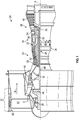
- FIG. 1 schematically illustrates a gas turbine engine 20.
- the gas turbine engine 20 is disclosed herein as a two-spool turbofan that generally incorporates a fan section 22, a compressor section 24, a combustor section 26 and a turbine section 28.
- the fan section 22 drives air along a bypass flow path B in a bypass duct, while the compressor section 24 drives air along a core flow path C for compression and communication into the combustor section 26 then expansion through the turbine section 28.
- FIG. 1 schematically illustrates a gas turbine engine 20.
- the gas turbine engine 20 is disclosed herein as a two-spool turbofan that generally incorporates a fan section 22, a compressor section 24, a combustor section 26 and a turbine section 28.
- the fan section 22 drives air along a bypass flow path B in a bypass duct
- the compressor section 24 drives air along a core flow path C for compression and communication into the combustor section 26 then expansion through the turbine section 28.
- the exemplary engine 20 generally includes a low speed spool 30 and a high speed spool 32 mounted for rotation about an engine central longitudinal axis A relative to an engine static structure 36 via several bearing systems 38. It should be understood that various bearing systems 38 at various locations may alternatively or additionally be provided, and the location of bearing systems 38 may be varied as appropriate to the application.
- the low speed spool 30 generally includes an inner shaft 40 that interconnects a fan 42, a low pressure compressor 44 and a low pressure turbine 46.
- the inner shaft 40 is connected to the fan 42 through a speed change mechanism, which in exemplary gas turbine engine 20 is illustrated as a geared architecture 48 to drive the fan 42 at a lower speed than the low speed spool 30.
- the high speed spool 32 includes an outer shaft 50 that interconnects a high pressure compressor 52 and high pressure turbine 54.
- a combustor 56 is arranged in exemplary gas turbine 20 between the high pressure compressor 52 and the high pressure turbine 54.
- An engine static structure 36 is arranged generally between the high pressure turbine 54 and the low pressure turbine 46.
- the engine static structure 36 further supports bearing systems 38 in the turbine section 28.
- the inner shaft 40 and the outer shaft 50 are concentric and rotate via bearing systems 38 about the engine central longitudinal axis A which is collinear with their longitudinal axes.
- each of the positions of the fan section 22, compressor section 24, combustor section 26, turbine section 28, and fan drive gear system 48 may be varied.
- gear system 48 may be located aft of combustor section 26 or even aft of turbine section 28, and fan section 22 may be positioned forward or aft of the location of gear system 48.
- the engine 20 in one example is a high-bypass geared aircraft engine.
- the engine 20 bypass ratio is greater than about six (6), with an example embodiment being greater than about ten (10)
- the geared architecture 48 is an epicyclic gear train, such as a planetary gear system or other gear system, with a gear reduction ratio of greater than about 2.3 and the low pressure turbine 46 has a pressure ratio that is greater than about five.
- the engine 20 bypass ratio is greater than about ten (10:1)
- the fan diameter is significantly larger than that of the low pressure compressor 44
- the low pressure turbine 46 has a pressure ratio that is greater than about five (5:1).
- Low pressure turbine 46 pressure ratio is pressure measured prior to inlet of low pressure turbine 46 as related to the pressure at the outlet of the low pressure turbine 46 prior to an exhaust nozzle.
- the geared architecture 48 may be an epicycle gear train, such as a planetary gear system or other gear system, with a gear reduction ratio of greater than about 2.3:1. It should be understood, however, that the above parameters are only exemplary of one embodiment of a geared architecture engine and that the present disclosure is applicable to other gas turbine engines including direct drive turbofans.
- the fan section 22 of the engine 20 is designed for a particular flight condition--typically cruise at about 0.8 Mach (274 m/s) and about 35,000 feet (10,668 meters).
- 'TSFC Thrust Specific Fuel Consumption
- Low fan pressure ratio is the pressure ratio across the fan blade alone, without a Fan Exit Guide Vane (“FEGV”) system.
- the low fan pressure ratio as disclosed herein according to one non-limiting embodiment is less than about 1.45.
- Low corrected fan tip speed is the actual fan tip speed in ft/sec divided by an industry standard temperature correction of [(Tram °R)/(518.7 °R)] 0.5 .
- the "Low corrected fan tip speed” as disclosed herein according to one non-limiting embodiment is less than about 1150 ft/second (350.5 m/sec).
- FIG. 2 schematically illustrates a hydrostatic advanced low leakage seal, or hybrid seal, indicated generally at 100.
- the hybrid seal 100 is mounted on a stator in some embodiments, it will be appreciated that the hybrid seal 100 could alternatively be mounted to a rotor.
- the hybrid seal 100 is intended to create a seal of the circumferential gap between two relatively rotating components, such as a fixed stator and a rotating rotor.
- the hybrid seal 100 includes a base portion 107 and at least one, but often a plurality of circumferentially spaced shoes 108 which are located in a non-contact position along the exterior surface of the rotor. Each shoe 108 is formed with a sealing surface 110.
- the term “axial” or “axially spaced” refers to a direction along the longitudinal axis of the stator and rotor, whereas “radial” refers to a direction perpendicular to the longitudinal axis.
- the hybrid seal 100 includes at least one circumferentially spaced spring element 114. Each spring element 114 is formed with at least one beam 116.
- the hybrid seal 100 is used in applications such as gas turbine engines, aerodynamic forces are developed which apply a fluid pressure to the shoe 108, which is counter balanced with the spring 114, causing it to move radially with respect to the rotor.
- the initial assembly point has a defined radial gap between the shoe 108 and the rotating surface, with no forces acting upon the shoe 108.
- the hybrid seal 100 is used to restrict flow between a high pressure region and a lower pressure region.
- the pressure drop across the shoe 108 creates a radial force on the shoe which is counter balanced by the spring 114.
- the gap between the shoe 108 and rotor increases, the pressure drop across the axial length of the seal shoe decreases.
- the reduction in pressure across the shoe 108 reduces the radial force acting on the shoe 108 such that the force balance between the pressure force and the spring 114 force causes the shoe 108 to be pushed radially inwardly toward the rotor, thus decreasing the gap.
- the pressure drop across the shoe 108 increases, causing an increase in radial pressure force, which overcomes the spring force, thus forcing the shoe 108 radially outwardly from the rotor.
- the spring elements 114 deflect and move with the shoe 108 to create a primary seal of the circumferential gap between the rotor and stator within predetermined design tolerances.
- Energy from adjacent mechanical or aerodynamic excitation sources may be transmitted to the seal 100, potentially creating a vibratory response in the seal 100.
- Such vibratory responses create vibratory stress leading to possible reduced life of the seal 100, and can be large enough to cause unintended deflections of the shoes 108.
- the vibratory response of the shoes 108 at their natural frequencies, while interacting with mechanical excitation or aerodynamic flow through the system, can reinforce each other causing unwanted vibration levels and possible deflection of the shoes 108 as the vibration is transmitted to all of the shoes 108.
- design considerations include increasing the first order natural frequency by reducing the mass of the shoes 108 and/or increasing the stiffness of the beams 116.
- the beams 116 can only be considered if the available pressure drop is still sufficient to deflect the shoe 108 relative to the rotor.
- the beams have a very low spring rate to maintain the force balance with the pressure drop across the shoe 108, and create the desired, small, controlled gap.
- the hybrid seal 100 operation requires low stiffness beams, making it difficult to achieve large increases in the resonant frequency through stiffness. For this reason it is preferable to decrease shoe mass.
- the pressure balance force is proportional to the arc length, and would require a reduction in spring stiffness to maintain the ability to control the gap.
- the practical means to reduce the stiffness is to reduce the thickness of the beams 116.
- the ability to design thin beams is not only limited by manufacturing techniques, but can result in beams which might be easily damaged during manufacture, assembly and use. Therefore, it is desired to decouple the arc length of the shoe 108 from the length of the spring 114.
- the embodiments disclosed herein include tab and slot features on adjacent shoes 108 that provide deflection shared end stops. As shown in FIG. 4 , a tab 120 extending from a first shoe 108a is in engagement with a slot feature 122 extending from a second shoe 108b that is adjacent shoe 108a to limit radial deflection of the seal.
- the radial deflection is limited by deflection limiting posts 124 extending axially from a rear support 126 of the structure to which the seal 100 is mounted to, such as a stator.
- Each post 124 is disposed within a respective aperture 128 that is defined by a structure extending radially from the shoe 108.
- each of the above-described deflection limiting features have a small radial height impact, which allows for a reduction in mass of the shoes 108 and providing an increased design space within the seal 100.
- the location of the beams 116 becomes independent of the shoe 108 since the beams 116 no longer must have a length that is less than the arc length of each shoe 108, as shown well in FIG. 2 , without having to increase the radial design space that would be required if the angle of the beams were required to be changed.
- the substantially parallel beams 116 maintain a generally tangent orientation relative to a rotating seal land and maintain the functionality of the seal 100, but allows the height and length of the beams 116 to become independent of the shoe 108 circumferential pitch.
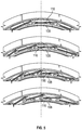
- FIG. 5 illustrates a comparison of four embodiments of the seal 100, with each having a different number of shoes 108 and therefore shoe arc lengths.
- Each illustrated seal 100 includes beams 116 with a common beam length. As shown, the arc length of each shoe 108 in each illustrated seal design does not impact or impair the ability to maintain a beam that is substantially equal to or longer than the arc length of the shoes.
- the beam length L includes end segments 170, which join the beams 116.
- the end segments 170 are part of the beams 116, either in an integrally formed manner or via a joining process, and it is the overall length of the beams 116 and the end segments 170 that constitute the beam length. It is this beam length that is substantially equal to or longer than the arc length, or circumferential pitch, of the shoes 108. "Substantially equal" to the arc length of the shoe 108 refers to 95% or more of the shoe length.
- decoupling the beam geometry form the shoe circumferential pitch allows for a larger range of radial motion of the seal 100 because the longer beams can deflect more, and at the same stress level. Therefore, shoe quantities can increase, thereby lowering mass to increase the first order natural frequency, while having beams that overlap.
Landscapes
- Engineering & Computer Science (AREA)
- General Engineering & Computer Science (AREA)
- Mechanical Engineering (AREA)
- Turbine Rotor Nozzle Sealing (AREA)
Abstract
Description
- Exemplary embodiments pertain to the art of gas turbine engines and, more particularly, to a hydrostatic seal with increased design space that may be used in gas turbine engines.
- Hydrostatic advanced low leakage seals, or hybrid seals, exhibit less leakage compared to traditional knife edge seals while exhibiting a longer life than brush seals. Some hybrid seals may be used to seal between a stator and a rotor within a gas turbine engine. The hybrid seal is mounted to one of the stator or the rotor to maintain a desired gap dimension between the hybrid seal and the other of the stator and rotor. The hybrid seal has the ability to 'track' the relative movement between the stator and the rotor throughout the engine operating profile when a pressure is applied across the seal. The hybrid seal tracking surface is attached to a solid carrier ring via continuous thin beams. These beams enable the low resistance movement of the hybrid seal in a radial direction. Prior hybrid seals have design space that is constrained by the beam connection to a shoe of the seal structure, and the need for end stops to limit deflection. The shoe quantity and the beam length limits set the range of operating speeds and radial travel variation while staying within structural limits.
- Disclosed is a hydrostatic advanced low leakage seal configured to be disposed between relatively rotatable components. The seal includes a base. The seal also includes a shoe extending circumferentially. The seal further includes a beam operatively coupling the shoe to the base, the beam having a beam length that is substantially equal to or greater than a circumferential pitch of the shoe.
- In addition to one or more of the features described above, or as an alternative, further embodiments may include that the beam is one of a plurality of beams, each of the plurality of beams having a beam length that is substantially equal to or greater than the circumferential pitch of the shoe.
- In addition to one or more of the features described above, or as an alternative, further embodiments may include that the plurality of beams are oriented parallel to each other.
- In addition to one or more of the features described above, or as an alternative, further embodiments may include a tab and a slot feature, the tab extending from the shoe proximate a first end of the shoe to be engageable with an end stop feature of an adjacent shoe, the slot feature located proximate a second end of the shoe to be engageable with another end stop feature of another adjacent shoe.
- Also disclosed is a seal assembly disposed in a gas turbine engine. Included is a first component and a second component, the first component and the second component relatively rotatable components. Also included is a first hydrostatic advanced low leakage seal disposed between the first component and the second component. The seal includes a base operatively coupled to one of the first component and the second component. The seal also includes a first shoe extending circumferentially. The seal further includes a first pair of beams operatively coupling the first shoe to the base, the first pair of beams having a beam length that is substantially equal to or greater than a circumferential pitch of the first shoe.
- In addition to one or more of the features described above, or as an alternative, further embodiments may include a second hydrostatic advanced low leakage seal that includes a second shoe extending circumferentially and positioned adjacent the first shoe. Also included is a second pair of beams operatively coupling the second shoe to the base, the second pair of beams each having a beam length that is substantially equal to or greater than a circumferential pitch of the second shoe. Further included is a tab extending from the second shoe proximate an end of the second shoe to be engageable with a slot feature of the first shoe.
- In addition to one or more of the features described above, or as an alternative, further embodiments may include that the first pair of beams are oriented parallel to each other and the second pair of beams are oriented parallel to each other.
- In addition to one or more of the features described above, or as an alternative, further embodiments may include a deflection limiting element extending axially from the first component, the deflection limiting element disposed within an aperture defined by an end structure of the first pair of beams.
- In addition to one or more of the features described above, or as an alternative, further embodiments may include that the deflection limiting element is a post.
- In addition to one or more of the features described above, or as an alternative, further embodiments may include that the first component is a stator and the second component is a rotor.
- In addition to one or more of the features described above, or as an alternative, further embodiments may include that the seal is operatively coupled to the stator.
- In addition to one or more of the features described above, or as an alternative, further embodiments may include that the seal is operatively coupled to the rotor.
- Further disclosed is a gas turbine engine including a compressor section, a combustor section, and a turbine section. The gas turbine engine also includes a seal assembly disposed in a gas turbine engine, the seal assembly comprising relatively rotatable components and a first hydrostatic advanced low leakage seal disposed between the relatively rotatable components. The first seal includes a base operatively coupled to one of the first component and the second component. The first seal also includes a first shoe extending circumferentially. The first seal further includes a first pair of beams operatively coupling the first shoe to the base, the first pair of beams having a beam length that is substantially equal to or greater than a circumferential pitch of the first shoe.
- In addition to one or more of the features described above, or as an alternative, further embodiments may include a second hydrostatic advanced low leakage seal. The second seal includes a second shoe extending circumferentially and positioned adjacent the first shoe. The second seal also includes a second pair of beams operatively coupling the second shoe to the base, the second pair of beams each having a beam length that is substantially equal to or greater than a circumferential pitch of the second shoe. The second seal further includes a tab extending from the second shoe proximate an end of the second shoe to be engageable with a slot feature of the first shoe.
- In addition to one or more of the features described above, or as an alternative, further embodiments may include that the first pair of beams are oriented parallel to each other and the second pair of beams are oriented parallel to each other.
- In addition to one or more of the features described above, or as an alternative, further embodiments may include a deflection limiting element extending axially from one of the relatively rotatable components, the deflection limiting element disposed within an aperture defined by an end structure of the first pair of beams.
- In addition to one or more of the features described above, or as an alternative, further embodiments may include that the deflection limiting element is a post.
- In addition to one or more of the features described above, or as an alternative, further embodiments may include that the relatively rotatable components comprise a stator and a rotor.
- In addition to one or more of the features described above, or as an alternative, further embodiments may include that the first seal is operatively coupled to the stator.
- In addition to one or more of the features described above, or as an alternative, further embodiments may include that the first seal is operatively coupled to the rotor.
- The following descriptions should not be considered limiting in any way. With reference to the accompanying drawings, like elements are numbered alike:
-
FIG. 1 is a side, partial cross-sectional view of a gas turbine engine; -
FIG. 2 is a perspective view of a portion of a hybrid seal assembly; -
FIG. 3 is a perspective view of a radial deflection limiting element; -
FIG. 4 is a seal portion engaged with the radial deflection limiting element; and -
FIG. 5 is a comparison of a plurality of seals having a different number of shoes. - A detailed description of one or more embodiments of the disclosed apparatus and method are presented herein by way of exemplification and not limitation with reference to the Figures.
-
FIG. 1 schematically illustrates agas turbine engine 20. Thegas turbine engine 20 is disclosed herein as a two-spool turbofan that generally incorporates afan section 22, acompressor section 24, acombustor section 26 and aturbine section 28. Thefan section 22 drives air along a bypass flow path B in a bypass duct, while thecompressor section 24 drives air along a core flow path C for compression and communication into thecombustor section 26 then expansion through theturbine section 28. Although depicted as a two-spool turbofan gas turbine engine in the disclosed non-limiting embodiment, it should be understood that the concepts described herein are not limited to use with two-spool turbofans as the teachings may be applied to other types of turbine engines including three-spool architectures. - The
exemplary engine 20 generally includes alow speed spool 30 and ahigh speed spool 32 mounted for rotation about an engine central longitudinal axis A relative to an enginestatic structure 36 viaseveral bearing systems 38. It should be understood thatvarious bearing systems 38 at various locations may alternatively or additionally be provided, and the location ofbearing systems 38 may be varied as appropriate to the application. - The
low speed spool 30 generally includes aninner shaft 40 that interconnects afan 42, alow pressure compressor 44 and alow pressure turbine 46. Theinner shaft 40 is connected to thefan 42 through a speed change mechanism, which in exemplarygas turbine engine 20 is illustrated as a gearedarchitecture 48 to drive thefan 42 at a lower speed than thelow speed spool 30. Thehigh speed spool 32 includes anouter shaft 50 that interconnects ahigh pressure compressor 52 andhigh pressure turbine 54. Acombustor 56 is arranged inexemplary gas turbine 20 between thehigh pressure compressor 52 and thehigh pressure turbine 54. An enginestatic structure 36 is arranged generally between thehigh pressure turbine 54 and thelow pressure turbine 46. The enginestatic structure 36 furthersupports bearing systems 38 in theturbine section 28. Theinner shaft 40 and theouter shaft 50 are concentric and rotate via bearingsystems 38 about the engine central longitudinal axis A which is collinear with their longitudinal axes. - The core airflow is compressed by the
low pressure compressor 44 then thehigh pressure compressor 52, mixed and burned with fuel in thecombustor 56, then expanded over thehigh pressure turbine 54 andlow pressure turbine 46. Theturbines low speed spool 30 andhigh speed spool 32 in response to the expansion. It will be appreciated that each of the positions of thefan section 22,compressor section 24,combustor section 26,turbine section 28, and fandrive gear system 48 may be varied. For example,gear system 48 may be located aft ofcombustor section 26 or even aft ofturbine section 28, andfan section 22 may be positioned forward or aft of the location ofgear system 48. - The
engine 20 in one example is a high-bypass geared aircraft engine. In a further example, theengine 20 bypass ratio is greater than about six (6), with an example embodiment being greater than about ten (10), the gearedarchitecture 48 is an epicyclic gear train, such as a planetary gear system or other gear system, with a gear reduction ratio of greater than about 2.3 and thelow pressure turbine 46 has a pressure ratio that is greater than about five. In one disclosed embodiment, theengine 20 bypass ratio is greater than about ten (10:1), the fan diameter is significantly larger than that of thelow pressure compressor 44, and thelow pressure turbine 46 has a pressure ratio that is greater than about five (5:1).Low pressure turbine 46 pressure ratio is pressure measured prior to inlet oflow pressure turbine 46 as related to the pressure at the outlet of thelow pressure turbine 46 prior to an exhaust nozzle. The gearedarchitecture 48 may be an epicycle gear train, such as a planetary gear system or other gear system, with a gear reduction ratio of greater than about 2.3:1. It should be understood, however, that the above parameters are only exemplary of one embodiment of a geared architecture engine and that the present disclosure is applicable to other gas turbine engines including direct drive turbofans. - A significant amount of thrust is provided by the bypass flow B due to the high bypass ratio. The
fan section 22 of theengine 20 is designed for a particular flight condition--typically cruise at about 0.8 Mach (274 m/s) and about 35,000 feet (10,668 meters). The flight condition of 0.8 Mach (274 m/s) and 35,000 feet (10,668 meters), with the engine at its best fuel consumption--also known as "bucket cruise Thrust Specific Fuel Consumption ('TSFC)"--is the industry standard parameter of lbm of fuel being burned divided by lbf of thrust the engine produces at that minimum point. "Low fan pressure ratio" is the pressure ratio across the fan blade alone, without a Fan Exit Guide Vane ("FEGV") system. The low fan pressure ratio as disclosed herein according to one non-limiting embodiment is less than about 1.45. "Low corrected fan tip speed" is the actual fan tip speed in ft/sec divided by an industry standard temperature correction of [(Tram °R)/(518.7 °R)]0.5. The "Low corrected fan tip speed" as disclosed herein according to one non-limiting embodiment is less than about 1150 ft/second (350.5 m/sec). -
FIG. 2 schematically illustrates a hydrostatic advanced low leakage seal, or hybrid seal, indicated generally at 100. Although thehybrid seal 100 is mounted on a stator in some embodiments, it will be appreciated that thehybrid seal 100 could alternatively be mounted to a rotor. Thehybrid seal 100 is intended to create a seal of the circumferential gap between two relatively rotating components, such as a fixed stator and a rotating rotor. Thehybrid seal 100 includes abase portion 107 and at least one, but often a plurality of circumferentially spacedshoes 108 which are located in a non-contact position along the exterior surface of the rotor. Eachshoe 108 is formed with a sealingsurface 110. For purposes of the present disclosure, the term "axial" or "axially spaced" refers to a direction along the longitudinal axis of the stator and rotor, whereas "radial" refers to a direction perpendicular to the longitudinal axis. - Under some operating conditions, it is desirable to limit the extent of radial movement of the
shoes 108 with respect to the rotor to maintain tolerances, such as the spacing between theshoes 108 and the facing surface of the rotor. Thehybrid seal 100 includes at least one circumferentially spacedspring element 114. Eachspring element 114 is formed with at least onebeam 116. - Particularly when the
hybrid seal 100 is used in applications such as gas turbine engines, aerodynamic forces are developed which apply a fluid pressure to theshoe 108, which is counter balanced with thespring 114, causing it to move radially with respect to the rotor. The initial assembly point has a defined radial gap between theshoe 108 and the rotating surface, with no forces acting upon theshoe 108. In operation, thehybrid seal 100 is used to restrict flow between a high pressure region and a lower pressure region. The pressure drop across theshoe 108 creates a radial force on the shoe which is counter balanced by thespring 114. In operation, when the gap between theshoe 108 and rotor increases, the pressure drop across the axial length of the seal shoe decreases. The reduction in pressure across theshoe 108 reduces the radial force acting on theshoe 108 such that the force balance between the pressure force and thespring 114 force causes theshoe 108 to be pushed radially inwardly toward the rotor, thus decreasing the gap. Conversely, in operation, when the gap closes below a desired level, the pressure drop across theshoe 108 increases, causing an increase in radial pressure force, which overcomes the spring force, thus forcing theshoe 108 radially outwardly from the rotor. Thespring elements 114 deflect and move with theshoe 108 to create a primary seal of the circumferential gap between the rotor and stator within predetermined design tolerances. - Energy from adjacent mechanical or aerodynamic excitation sources (e.g. rotor imbalance, flow through the seal, other sections of the engine, etc.) may be transmitted to the
seal 100, potentially creating a vibratory response in theseal 100. Such vibratory responses create vibratory stress leading to possible reduced life of theseal 100, and can be large enough to cause unintended deflections of theshoes 108. The vibratory response of theshoes 108 at their natural frequencies, while interacting with mechanical excitation or aerodynamic flow through the system, can reinforce each other causing unwanted vibration levels and possible deflection of theshoes 108 as the vibration is transmitted to all of theshoes 108. Because the resonant frequency response is a function of the square root of the ratio ofspring element 114 stiffness to the mass, design considerations include increasing the first order natural frequency by reducing the mass of theshoes 108 and/or increasing the stiffness of thebeams 116. - Increasing the stiffness of the
beams 116 can only be considered if the available pressure drop is still sufficient to deflect theshoe 108 relative to the rotor. In practice, the beams have a very low spring rate to maintain the force balance with the pressure drop across theshoe 108, and create the desired, small, controlled gap. Thehybrid seal 100 operation requires low stiffness beams, making it difficult to achieve large increases in the resonant frequency through stiffness. For this reason it is preferable to decrease shoe mass. - Decreasing the mass of the
shoes 108, by increasing the number ofshoes 108 in the assembledhybrid seal 100 is beneficial. With conventional hybrid seal designs, the length of thespring 114 would also decrease. However, the radial deflection limiters would impose a fixed circumferential geometric constraint, due to manufacturing and structural requirements and therefore the radial deflection limiters would become a proportionally larger percentage of the circumferential space available for thespring 114 and the deflection limiters. Thus it can be shown, increasing the shoe quantity to reduce theshoe 108 mass, would reduce the circumferential arc length available forshoe 108 andspring 114, and the deflection limiters would impose a proportionally greater reduction in thespring 114 length, which results in astiffer spring 114. However, the pressure balance force is proportional to the arc length, and would require a reduction in spring stiffness to maintain the ability to control the gap. For a given length ofspring 114, the practical means to reduce the stiffness is to reduce the thickness of thebeams 116. In practice, the ability to design thin beams is not only limited by manufacturing techniques, but can result in beams which might be easily damaged during manufacture, assembly and use. Therefore, it is desired to decouple the arc length of theshoe 108 from the length of thespring 114. - Referring now to
FIGS. 3 and 4 , rather than relying on end stops and radial deflection limit features that extend completely, or nearly completely, between theshoe 108 and thebase portion 107 of the seal 100 - as with prior hybrid seals - the embodiments disclosed herein include tab and slot features onadjacent shoes 108 that provide deflection shared end stops. As shown inFIG. 4 , atab 120 extending from afirst shoe 108a is in engagement with aslot feature 122 extending from a second shoe 108b that isadjacent shoe 108a to limit radial deflection of the seal. The radial deflection is limited bydeflection limiting posts 124 extending axially from arear support 126 of the structure to which theseal 100 is mounted to, such as a stator. Eachpost 124 is disposed within arespective aperture 128 that is defined by a structure extending radially from theshoe 108. - Each of the above-described deflection limiting features have a small radial height impact, which allows for a reduction in mass of the
shoes 108 and providing an increased design space within theseal 100. For example, the location of thebeams 116 becomes independent of theshoe 108 since thebeams 116 no longer must have a length that is less than the arc length of eachshoe 108, as shown well inFIG. 2 , without having to increase the radial design space that would be required if the angle of the beams were required to be changed. Additionally, by maintaining the same beam angle with the same length, the substantiallyparallel beams 116 maintain a generally tangent orientation relative to a rotating seal land and maintain the functionality of theseal 100, but allows the height and length of thebeams 116 to become independent of theshoe 108 circumferential pitch. -
FIG. 5 illustrates a comparison of four embodiments of theseal 100, with each having a different number ofshoes 108 and therefore shoe arc lengths. Each illustratedseal 100 includesbeams 116 with a common beam length. As shown, the arc length of eachshoe 108 in each illustrated seal design does not impact or impair the ability to maintain a beam that is substantially equal to or longer than the arc length of the shoes. - Referring again to
FIG. 2 , the term "beam length" used herein is defined by length L. The beam length L includesend segments 170, which join thebeams 116. Theend segments 170 are part of thebeams 116, either in an integrally formed manner or via a joining process, and it is the overall length of thebeams 116 and theend segments 170 that constitute the beam length. It is this beam length that is substantially equal to or longer than the arc length, or circumferential pitch, of theshoes 108. "Substantially equal" to the arc length of theshoe 108 refers to 95% or more of the shoe length. - Advantageously, decoupling the beam geometry form the shoe circumferential pitch allows for a larger range of radial motion of the
seal 100 because the longer beams can deflect more, and at the same stress level. Therefore, shoe quantities can increase, thereby lowering mass to increase the first order natural frequency, while having beams that overlap. - The term "about" is intended to include the degree of error associated with measurement of the particular quantity based upon the equipment available at the time of filing the application. For example, "about" can include a range of ± 8% or 5%, or 2% of a given value.
- The terminology used herein is for the purpose of describing particular embodiments only and is not intended to be limiting of the present disclosure. As used herein, the singular forms "a", "an" and "the" are intended to include the plural forms as well, unless the context clearly indicates otherwise. It will be further understood that the terms "comprises" and/or "comprising," when used in this specification, specify the presence of stated features, integers, steps, operations, elements, and/or components, but do not preclude the presence or addition of one or more other features, integers, steps, operations, element components, and/or groups thereof.
- While the present disclosure has been described with reference to an exemplary embodiment or embodiments, it will be understood by those skilled in the art that various changes may be made and equivalents may be substituted for elements thereof without departing from the scope of the present disclosure. In addition, many modifications may be made to adapt a particular situation or material to the teachings of the present disclosure without departing from the scope thereof. Therefore, it is intended that the present disclosure not be limited to the particular embodiment disclosed as the best mode contemplated for carrying out this present disclosure, but that the present disclosure will include all embodiments falling within the scope of the claims.
Claims (13)
- A hydrostatic advanced low leakage seal (100) configured to be disposed between relatively rotatable components, the seal comprising:abase (107);a shoe (108) extending circumferentially; anda beam (116) operatively coupling the shoe (108) to the base (107), the beam (116) having a beam length (L) that is substantially equal to or greater than a circumferential pitch of the shoe (108).
- The seal (100) of claim 1, wherein the beam (116) is one of a plurality of beams, each of the plurality of beams having a beam length (L) that is substantially equal to or greater than the circumferential pitch of the shoe (108).
- The seal (100) of claim 2, wherein the plurality of beams (116) are oriented parallel to each other.
- The seal (100) of any of claims 1 to 3, further comprising a tab (120) and a slot feature (122), the tab (120) extending from the shoe (108a) proximate a first end of the shoe to be engageable with an end stop feature of an adjacent shoe (108b), the slot (122) feature located proximate a second end of the shoe (108a) to be engageable with another end stop feature of another adjacent shoe.
- A seal assembly disposed in a gas turbine engine, the seal assembly comprising:a first component;a second component, the first component and the second component relatively rotatable components; anda first hydrostatic advanced low leakage seal (100) as claimed in any of claims 1 to 4, disposed between the first component and the second component, wherein:the base (107) is operatively coupled to one of the first component and the second component;the shoe is a first shoe (108a) extending circumferentially; andthe beam is one of a first pair of beams (116) operatively coupling the first shoe (108a) to the base (107), the first pair of beams (116) having a beam length (L) that is substantially equal to or greater than a circumferential pitch of the first shoe.
- The seal assembly of claim 5, further comprising a second hydrostatic advanced low leakage seal (100) comprising:a second shoe (108b) extending circumferentially and positioned adjacent the first shoe (108a);a second pair of beams (116) operatively coupling the second shoe (108b) to the base (107), the second pair of beams each having a beam length that is substantially equal to or greater than a circumferential pitch of the second shoe; anda tab (120) extending from the second shoe proximate an end of the second shoe to be engageable with a slot feature (122) of the first shoe.
- The seal assembly of claim 6, wherein the first pair of beams (116) are oriented parallel to each other and the second pair of beams are oriented parallel to each other.
- The seal assembly of any of claims 5 to 7, further comprising a deflection limiting element (124) extending axially from the first component, the deflection limiting element disposed within an aperture (128) defined by an end structure (170) of the first pair of beams (116).
- The seal assembly of claim 8, wherein the deflection limiting element (124) is a post.
- The seal assembly of any of claims 5 to 9, wherein the first component is a stator and the second component is a rotor.
- The seal assembly of claim 10, wherein the seal (100) is operatively coupled to the stator.
- The seal assembly of claim 10, wherein the seal (100) is operatively coupled to the rotor.
- A gas turbine engine (20) comprising:a compressor section (24);a combustor section (26);a turbine section (28); anda seal assembly as claimed in any of claims 5 to 12.
Applications Claiming Priority (1)
| Application Number | Priority Date | Filing Date | Title |
|---|---|---|---|
| US16/202,810 US11199102B2 (en) | 2018-11-28 | 2018-11-28 | Hydrostatic seal with increased design space |
Publications (1)
| Publication Number | Publication Date |
|---|---|
| EP3660274A1 true EP3660274A1 (en) | 2020-06-03 |
Family
ID=68732782
Family Applications (1)
| Application Number | Title | Priority Date | Filing Date |
|---|---|---|---|
| EP19212326.3A Pending EP3660274A1 (en) | 2018-11-28 | 2019-11-28 | Hydrostatic seal with increased design space |
Country Status (2)
| Country | Link |
|---|---|
| US (1) | US11199102B2 (en) |
| EP (1) | EP3660274A1 (en) |
Families Citing this family (7)
| Publication number | Priority date | Publication date | Assignee | Title |
|---|---|---|---|---|
| US11111805B2 (en) | 2018-11-28 | 2021-09-07 | Raytheon Technologies Corporation | Multi-component assembled hydrostatic seal |
| US11674402B2 (en) | 2018-11-28 | 2023-06-13 | Raytheon Technologies Corporation | Hydrostatic seal with non-parallel beams for anti-tipping |
| US11421543B2 (en) * | 2018-11-28 | 2022-08-23 | Raytheon Technologies Corporation | Hydrostatic seal with asymmetric beams for anti-tipping |
| US11773741B2 (en) | 2021-06-09 | 2023-10-03 | General Electric Company | Compliant shroud designs with variable stiffness |
| CN116517641A (en) * | 2022-01-24 | 2023-08-01 | 通用电气公司 | Flexible shield of bending beam stacking structure |
| FR3146938A1 (en) * | 2023-03-23 | 2024-09-27 | Safran Aircraft Engines | Stator assembly for an aircraft turbomachine |
| US12503950B2 (en) * | 2024-05-03 | 2025-12-23 | Rtx Corporation | Non-contact seal shoe with diffuser structure |
Citations (5)
| Publication number | Priority date | Publication date | Assignee | Title |
|---|---|---|---|---|
| FR2675560A1 (en) * | 1991-04-18 | 1992-10-23 | Alsthom Gec | Sealing gasket for rotating shaft |
| CN105545375A (en) * | 2015-12-14 | 2016-05-04 | 中国燃气涡轮研究院 | Double-beam finger seal device |
| US20160130963A1 (en) * | 2014-11-07 | 2016-05-12 | United Technologies Corporation | Gas turbine engine and seal assembly therefore |
| EP3290646A1 (en) * | 2016-08-29 | 2018-03-07 | United Technologies Corporation | Floating, non-contact seal with angled beams |
| CN108005793A (en) * | 2017-12-27 | 2018-05-08 | 中国航发四川燃气涡轮研究院 | A kind of tile sealing structure |
Family Cites Families (33)
| Publication number | Priority date | Publication date | Assignee | Title |
|---|---|---|---|---|
| US5755445A (en) | 1996-08-23 | 1998-05-26 | Alliedsignal Inc. | Noncontacting finger seal with hydrodynamic foot portion |
| US7896352B2 (en) | 2003-05-01 | 2011-03-01 | Justak John F | Seal with stacked sealing elements |
| US7410173B2 (en) | 2003-05-01 | 2008-08-12 | Justak John F | Hydrodynamic brush seal |
| US20040217549A1 (en) | 2003-05-01 | 2004-11-04 | Justak John F. | Hydrodynamic brush seal |
| US8002285B2 (en) | 2003-05-01 | 2011-08-23 | Justak John F | Non-contact seal for a gas turbine engine |
| US8172232B2 (en) | 2003-05-01 | 2012-05-08 | Advanced Technologies Group, Inc. | Non-contact seal for a gas turbine engine |
| US7216871B1 (en) * | 2004-05-04 | 2007-05-15 | Advanced Components & Materials, Inc. | Non-contacting seal for rotating surfaces |
| US7735833B2 (en) * | 2006-11-14 | 2010-06-15 | The University Of Akron | Double padded finger seal |
| WO2008140451A1 (en) | 2007-05-14 | 2008-11-20 | Rexnord Industries Llc | Non-contacting seal for rotating surfaces |
| US8740225B2 (en) | 2009-06-03 | 2014-06-03 | Exponential Technologies, Inc. | Hydrodynamic bore seal |
| GB0910536D0 (en) | 2009-06-18 | 2009-07-29 | Rolls Royce Plc | A compliant element |
| US9145785B2 (en) | 2011-03-04 | 2015-09-29 | General Electric Company | Aerodynamic seal assemblies for turbo-machinery |
| US20130195627A1 (en) | 2012-01-27 | 2013-08-01 | Jorn A. Glahn | Thrust balance system for gas turbine engine |
| WO2015147967A1 (en) | 2014-03-27 | 2015-10-01 | United Technologies Corporation | Gas turbine engine and seal assembly therefore |
| US20150285152A1 (en) | 2014-04-03 | 2015-10-08 | United Technologies Corporation | Gas turbine engine and seal assembly therefore |
| US9359908B2 (en) | 2014-07-08 | 2016-06-07 | General Electric Company | Film riding seal assembly for turbomachinery |
| US10801348B2 (en) * | 2014-10-14 | 2020-10-13 | Raytheon Technologies Corporation | Non-contacting dynamic seal |
| US9988921B2 (en) * | 2014-10-17 | 2018-06-05 | United Technologies Corporation | Circumferential seal with seal dampening elements |
| US10161259B2 (en) | 2014-10-28 | 2018-12-25 | General Electric Company | Flexible film-riding seal |
| US10094232B2 (en) | 2015-08-13 | 2018-10-09 | United Technologies Corporation | Self crystalline orientation for increased compliance |
| US10221714B2 (en) | 2016-01-22 | 2019-03-05 | United Technologies Corporation | Secondary seal device(s) with alignment tab(s) |
| US10428672B2 (en) | 2016-02-08 | 2019-10-01 | United Technologies Corporation | Floating, non-contact seal and dimensions thereof |
| US10060535B2 (en) | 2016-02-25 | 2018-08-28 | United Technologies Corporation | Shaped spring element for a non-contact seal device |
| US10100657B2 (en) | 2016-08-15 | 2018-10-16 | United Technologies Corporation | Non-contact seal with monolithic/unitary carrier structure |
| US10370996B2 (en) | 2016-08-23 | 2019-08-06 | United Technologies Corporation | Floating, non-contact seal with offset build clearance for load imbalance |
| US10550708B2 (en) | 2016-08-31 | 2020-02-04 | United Technologies Corporation | Floating, non-contact seal with at least three beams |
| US10415413B2 (en) | 2016-09-01 | 2019-09-17 | United Technologies Corporation | Floating non-contact seal vertical lip |
| US10641180B2 (en) | 2017-06-15 | 2020-05-05 | United Technologies Corporation | Hydrostatic non-contact seal with varied thickness beams |
| US10718270B2 (en) | 2017-06-15 | 2020-07-21 | Raytheon Technologies Corporation | Hydrostatic non-contact seal with dual material |
| US11143194B2 (en) | 2018-11-13 | 2021-10-12 | Raytheon Technologies Corporation | Seal disassembly aid |
| US11111805B2 (en) | 2018-11-28 | 2021-09-07 | Raytheon Technologies Corporation | Multi-component assembled hydrostatic seal |
| US11421543B2 (en) | 2018-11-28 | 2022-08-23 | Raytheon Technologies Corporation | Hydrostatic seal with asymmetric beams for anti-tipping |
| US11674402B2 (en) | 2018-11-28 | 2023-06-13 | Raytheon Technologies Corporation | Hydrostatic seal with non-parallel beams for anti-tipping |
-
2018
- 2018-11-28 US US16/202,810 patent/US11199102B2/en active Active
-
2019
- 2019-11-28 EP EP19212326.3A patent/EP3660274A1/en active Pending
Patent Citations (5)
| Publication number | Priority date | Publication date | Assignee | Title |
|---|---|---|---|---|
| FR2675560A1 (en) * | 1991-04-18 | 1992-10-23 | Alsthom Gec | Sealing gasket for rotating shaft |
| US20160130963A1 (en) * | 2014-11-07 | 2016-05-12 | United Technologies Corporation | Gas turbine engine and seal assembly therefore |
| CN105545375A (en) * | 2015-12-14 | 2016-05-04 | 中国燃气涡轮研究院 | Double-beam finger seal device |
| EP3290646A1 (en) * | 2016-08-29 | 2018-03-07 | United Technologies Corporation | Floating, non-contact seal with angled beams |
| CN108005793A (en) * | 2017-12-27 | 2018-05-08 | 中国航发四川燃气涡轮研究院 | A kind of tile sealing structure |
Also Published As
| Publication number | Publication date |
|---|---|
| US20200165928A1 (en) | 2020-05-28 |
| US11199102B2 (en) | 2021-12-14 |
Similar Documents
| Publication | Publication Date | Title |
|---|---|---|
| US11199102B2 (en) | Hydrostatic seal with increased design space | |
| EP3659741B1 (en) | Multi-component assembled hydrostatic seal | |
| EP3677817B1 (en) | Hydrostatic seal with extended housing | |
| EP3677818B1 (en) | Cantilevered hydrostatic advanced low leakage seal | |
| US20150285152A1 (en) | Gas turbine engine and seal assembly therefore | |
| EP3660362B1 (en) | Hydrostatic seal with asymmetric beams for anti-tipping | |
| EP3726062A1 (en) | Inclination of forward and aft groove walls of casing treatment for gas turbine engine | |
| EP3680521B1 (en) | Hydrostatic seal with aft tooth | |
| EP3660363B1 (en) | Hydrostatic seal with non-parallel beams for anti-tipping | |
| EP3722560B1 (en) | Hydrostatic seal with secondary seal structural protection | |
| EP3502497A1 (en) | Flexible preloaded ball bearing assembly | |
| EP3786418A1 (en) | Hydrostatic seal with seal stops | |
| EP3789589B1 (en) | Hydrostatic seal | |
| EP3789588B1 (en) | Hydrostatic seal aligned with rotor rotation | |
| US11168565B2 (en) | Heat shield insert | |
| EP3739241A1 (en) | Brush secondary seal for cantilevered hydrostatic advanced low leakage seal | |
| EP3789586B1 (en) | Aerodynamic element assembly for a gas turbine engine | |
| EP3715641B1 (en) | Notched axial flange for a split case compressor | |
| EP4372208A1 (en) | Seal for gas turbine engine |
Legal Events
| Date | Code | Title | Description |
|---|---|---|---|
| PUAI | Public reference made under article 153(3) epc to a published international application that has entered the european phase |
Free format text: ORIGINAL CODE: 0009012 |
|
| STAA | Information on the status of an ep patent application or granted ep patent |
Free format text: STATUS: THE APPLICATION HAS BEEN PUBLISHED |
|
| AK | Designated contracting states |
Kind code of ref document: A1 Designated state(s): AL AT BE BG CH CY CZ DE DK EE ES FI FR GB GR HR HU IE IS IT LI LT LU LV MC MK MT NL NO PL PT RO RS SE SI SK SM TR |
|
| AX | Request for extension of the european patent |
Extension state: BA ME |
|
| STAA | Information on the status of an ep patent application or granted ep patent |
Free format text: STATUS: REQUEST FOR EXAMINATION WAS MADE |
|
| 17P | Request for examination filed |
Effective date: 20201203 |
|
| RBV | Designated contracting states (corrected) |
Designated state(s): AL AT BE BG CH CY CZ DE DK EE ES FI FR GB GR HR HU IE IS IT LI LT LU LV MC MK MT NL NO PL PT RO RS SE SI SK SM TR |
|
| RAP1 | Party data changed (applicant data changed or rights of an application transferred) |
Owner name: RAYTHEON TECHNOLOGIES CORPORATION |
|
| STAA | Information on the status of an ep patent application or granted ep patent |
Free format text: STATUS: EXAMINATION IS IN PROGRESS |
|
| 17Q | First examination report despatched |
Effective date: 20220503 |
|
| RAP3 | Party data changed (applicant data changed or rights of an application transferred) |
Owner name: RTX CORPORATION |