EP3659952A1 - Sheet accumulating equipment - Google Patents
Sheet accumulating equipment Download PDFInfo
- Publication number
- EP3659952A1 EP3659952A1 EP19211350.4A EP19211350A EP3659952A1 EP 3659952 A1 EP3659952 A1 EP 3659952A1 EP 19211350 A EP19211350 A EP 19211350A EP 3659952 A1 EP3659952 A1 EP 3659952A1
- Authority
- EP
- European Patent Office
- Prior art keywords
- sheets
- accumulation
- plane
- sheet
- accumulated
- Prior art date
- Legal status (The legal status is an assumption and is not a legal conclusion. Google has not performed a legal analysis and makes no representation as to the accuracy of the status listed.)
- Granted
Links
Images




Classifications
-
- B—PERFORMING OPERATIONS; TRANSPORTING
- B65—CONVEYING; PACKING; STORING; HANDLING THIN OR FILAMENTARY MATERIAL
- B65H—HANDLING THIN OR FILAMENTARY MATERIAL, e.g. SHEETS, WEBS, CABLES
- B65H39/00—Associating, collating, or gathering articles or webs
- B65H39/10—Associating articles from a single source, to form, e.g. a writing-pad
-
- B—PERFORMING OPERATIONS; TRANSPORTING
- B65—CONVEYING; PACKING; STORING; HANDLING THIN OR FILAMENTARY MATERIAL
- B65H—HANDLING THIN OR FILAMENTARY MATERIAL, e.g. SHEETS, WEBS, CABLES
- B65H31/00—Pile receivers
- B65H31/34—Apparatus for squaring-up piled articles
- B65H31/36—Auxiliary devices for contacting each article with a front stop as it is piled
-
- B—PERFORMING OPERATIONS; TRANSPORTING
- B65—CONVEYING; PACKING; STORING; HANDLING THIN OR FILAMENTARY MATERIAL
- B65H—HANDLING THIN OR FILAMENTARY MATERIAL, e.g. SHEETS, WEBS, CABLES
- B65H29/00—Delivering or advancing articles from machines; Advancing articles to or into piles
- B65H29/12—Delivering or advancing articles from machines; Advancing articles to or into piles by means of the nip between two, or between two sets of, moving tapes or bands or rollers
- B65H29/14—Delivering or advancing articles from machines; Advancing articles to or into piles by means of the nip between two, or between two sets of, moving tapes or bands or rollers and introducing into a pile
-
- B—PERFORMING OPERATIONS; TRANSPORTING
- B65—CONVEYING; PACKING; STORING; HANDLING THIN OR FILAMENTARY MATERIAL
- B65H—HANDLING THIN OR FILAMENTARY MATERIAL, e.g. SHEETS, WEBS, CABLES
- B65H29/00—Delivering or advancing articles from machines; Advancing articles to or into piles
- B65H29/52—Stationary guides or smoothers
-
- B—PERFORMING OPERATIONS; TRANSPORTING
- B65—CONVEYING; PACKING; STORING; HANDLING THIN OR FILAMENTARY MATERIAL
- B65H—HANDLING THIN OR FILAMENTARY MATERIAL, e.g. SHEETS, WEBS, CABLES
- B65H31/00—Pile receivers
- B65H31/04—Pile receivers with movable end support arranged to recede as pile accumulates
- B65H31/08—Pile receivers with movable end support arranged to recede as pile accumulates the articles being piled one above another
- B65H31/10—Pile receivers with movable end support arranged to recede as pile accumulates the articles being piled one above another and applied at the top of the pile
-
- B—PERFORMING OPERATIONS; TRANSPORTING
- B65—CONVEYING; PACKING; STORING; HANDLING THIN OR FILAMENTARY MATERIAL
- B65H—HANDLING THIN OR FILAMENTARY MATERIAL, e.g. SHEETS, WEBS, CABLES
- B65H31/00—Pile receivers
- B65H31/04—Pile receivers with movable end support arranged to recede as pile accumulates
- B65H31/12—Devices relieving the weight of the pile or permitting or effecting movement of the pile end support during piling
- B65H31/16—Fluid-pressure devices
-
- B—PERFORMING OPERATIONS; TRANSPORTING
- B65—CONVEYING; PACKING; STORING; HANDLING THIN OR FILAMENTARY MATERIAL
- B65H—HANDLING THIN OR FILAMENTARY MATERIAL, e.g. SHEETS, WEBS, CABLES
- B65H31/00—Pile receivers
- B65H31/04—Pile receivers with movable end support arranged to recede as pile accumulates
- B65H31/12—Devices relieving the weight of the pile or permitting or effecting movement of the pile end support during piling
- B65H31/18—Positively-acting mechanical devices
-
- B—PERFORMING OPERATIONS; TRANSPORTING
- B65—CONVEYING; PACKING; STORING; HANDLING THIN OR FILAMENTARY MATERIAL
- B65H—HANDLING THIN OR FILAMENTARY MATERIAL, e.g. SHEETS, WEBS, CABLES
- B65H31/00—Pile receivers
- B65H31/20—Pile receivers adjustable for different article sizes
-
- B—PERFORMING OPERATIONS; TRANSPORTING
- B65—CONVEYING; PACKING; STORING; HANDLING THIN OR FILAMENTARY MATERIAL
- B65H—HANDLING THIN OR FILAMENTARY MATERIAL, e.g. SHEETS, WEBS, CABLES
- B65H31/00—Pile receivers
- B65H31/30—Arrangements for removing completed piles
- B65H31/3027—Arrangements for removing completed piles by the nip between moving belts or rollers
-
- B—PERFORMING OPERATIONS; TRANSPORTING
- B65—CONVEYING; PACKING; STORING; HANDLING THIN OR FILAMENTARY MATERIAL
- B65H—HANDLING THIN OR FILAMENTARY MATERIAL, e.g. SHEETS, WEBS, CABLES
- B65H2402/00—Constructional details of the handling apparatus
- B65H2402/30—Supports; Subassemblies; Mountings thereof
-
- B—PERFORMING OPERATIONS; TRANSPORTING
- B65—CONVEYING; PACKING; STORING; HANDLING THIN OR FILAMENTARY MATERIAL
- B65H—HANDLING THIN OR FILAMENTARY MATERIAL, e.g. SHEETS, WEBS, CABLES
- B65H2404/00—Parts for transporting or guiding the handled material
- B65H2404/20—Belts
- B65H2404/26—Particular arrangement of belt, or belts
- B65H2404/268—Arrangement of belts facing a transport surface, e.g. contact glass in copy machine
-
- B—PERFORMING OPERATIONS; TRANSPORTING
- B65—CONVEYING; PACKING; STORING; HANDLING THIN OR FILAMENTARY MATERIAL
- B65H—HANDLING THIN OR FILAMENTARY MATERIAL, e.g. SHEETS, WEBS, CABLES
- B65H2511/00—Dimensions; Position; Numbers; Identification; Occurrences
- B65H2511/10—Size; Dimensions
- B65H2511/11—Length
Definitions
- the present invention relates to a sheet accumulating equipment.
- the invention relates to a sheet accumulating equipment comprising an accumulation plane for sheets entering along a feeding direction, a plurality of elongated-type driving belts, with respective lower branches positioned in parallel slightly above the accumulation plane and ramp members arranged along the path of the sheets for lifting and engaging the sheets with the lower branches of the belts and in which the driving belts are motorized for dragging the raised sheets and depositing them by jump on the accumulation plane or on sheets in accumulation, in accordance with the introductory part of the main claim.
- Equipments of this type are used in mail sending systems, with sheets of limited dimensions (A4), upstream of respective folding devices, for following insertions into envelopes.
- General object of the present invention is to provide a sheet accumulating equipment of the type including driving belts and ramp members which can be used with sheets of large dimensions and different length at a relatively high speed for subsequent treatments of the accumulated sheets in a reliable and precise manner.
- the sheet accumulating equipment comprises a suspension group of the accumulation plane and a shifting command mechanism.
- the suspension assembly is structured to allow a vertical compensation shifting of the accumulation plane with respect to the ramp members so as to modify the height of the jump for the entering sheets, while the shifting command mechanism is provided for shifting the accumulation plane as function of the number and/or thickness of the sheets to be accumulated, while the ramp members are longitudinally shiftable for limiting, by means of the ramp members, the longitudinal extension of a sheet gathering area functionally to the length of the sheets to be accumulated according to the characteristic part of the main claim.
- FIGS 1 , 2 and 2a represent an accumulating equipment 19 for sheets 20 in accordance with the invention.
- the equipment 19 includes a frame 21 with two side walls 22 and 23, a front 24 with an input gate 26 and a back 27 with an output gate 28.
- the equipment 19 receives the sheets 20 from a feeding apparatus along a feeding direction "F" and, on an accumulating configuration, accumulates the sheets on a stack of accumulated sheets 29.
- the equipment 19 forwards the stack of accumulated sheets 29, through the output gate 28 and along the same direction "F", to a user apparatus for subsequent use.
- the sheets 20 come from a paper cutter "CM” with output rollers 31, while the stack of the accumulated sheets 29 is forwarded to an "FM” folder with input rollers 32 for the folding of the stack.
- the accumulating equipment 19 comprises a plurality of driving belts 33, an accumulation plane 34, horizontal in use, for the entering and accumulating sheets 20, ramp members or " diverters " 36 individually associated with the driving belts 33, a sheet arrest group 37, a forwarding mechanism 38 for the stack of accumulated sheets 29, a control panel 39 and an electronic control unit 40.
- the equipment 19 further comprises sensor elements, not shown, arranged along the path of the sheets and connected to the electronic unit 40 for counting the sheets in accumulation and detecting some operating conditions and anomalies.
- the driving belts 33 are of the round type ( O ring or spaghetti belt ), longitudinally elongated and have branches parallel to the feeding direction "F" with axes lying on a geometrical plane perpendicular to the accumulation plane 34. Specifically, the belts 33 are stretched between grooved input pulleys 41 and grooved output pulleys 42 and in which respective lower branches 43 of the belts are arranged a short distance from the plane 34 and define, in the condition of tangency, a geometric plane of movement "GM" for the sheets 20 .
- the pulleys 41 and 42 are keyed on shafts 44 and 46 which are supported between the side walls 22 and 23 of the frame 21 in proximity of the input gate 26 and, respectively, near the output gate 28.
- the shaft 44 is idle, while the shaft 46 is connected, through a transmission mechanism with belt and pulley (not shown), to a motor 48 for the driving of the pulleys 42 with movement of the lower branches 43 along the direction "F".
- the accumulation plane 34 extends in length between a front edge 49 adjacent to the input gate 26 and a rear edge 51 spaced away from the output gate 28 ( Figs. 2b , 4 and 6 ).
- the accumulation plane 34 defines longitudinal slots 52, while the ramp members 36 project upwards from the slots 52, above the geometric plane "GM" in an intermediate zone of the plane 34.
- the ramp members 36 each have an inclined surface 56 and a step 57 and define a groove 58 in the upper part. At rest, the lower branches 43 of the driving belts 33 are freely received in the grooves 58 of the ramp members and in the condition of tangency with the geometric plane "GM".
- the sheets 20 entering the equipment 19 are pushed by the output rollers of the external feeding apparatus into the space existing between the lower branches 43 of the driving belts 33 and the accumulation plane 34 up to the ramp members 36 with consequent lifting of the leading edges of the sheets.
- the sheets are engaged by the branches 43 and dragged along the inclined surfaces 56.
- the action continues with the passage on the ramp members 36 and the dragging of the sheets below the "GM" plane. It occurs into a collection area 59 (see Fig. 2a ) downstream of the step 57, along the accumulation plane 34 or on the accumulating sheets.
- the sheets 20 disengage from the belts 33 and are deposited by jump on the plane 34 or on the accumulating sheets in the collection area 59.
- the sheet arrest group 37 operates on the collection area 59 and is switchable between a closed disposition and an open disposition.
- the arrest group 37 is provided for arresting the accumulating sheets 29 in the closed disposition, and releasing the accumulated sheets 29 in the open disposition.
- a series of leaf springs 61 exert a stabilizing action on the accumulating sheets in the collection area 59.
- the leaf springs 61 extend longitudinally above the plane 34 with inclination from top to bottom and each have a free end and an end fixed on a crossbar 62.
- the leaf springs 61 are interposed between the belts 33 for the entire width of the accumulation plane 34, downstream of the ramp members 36 and, in the operating conditions, rest lightly with their free ends on the accumulating sheets on a part of the plane 34 adjacent to the rear edge 51.
- a platform 63 ( Figs. 2b and 2c ), which is arranged behind the accumulation plate, slightly below the geometric plane "GM”, and completes the collection area 59.
- the platform 63 crosses the output gate 28 and defines an internal section projecting inwards and an external section projecting outward.
- the internal section of the platform 63 has a bevelled front edge 64, which is arranged in front of the edge 51 of the accumulating plane 34 and so as to leave a space of separation with respect to the plane 34 and receiving the accumulating sheets.
- the external section of the platform 63 accommodates the leading edges of the accumulating sheets, while a bank member of the sheet arrest group 37 in the closed disposition of the arrest group operates on the platform 63 for defining rearward the collection area 59 with accurate vertical alignment of the leading edges of the accumulated sheets.
- the bank member of the sheet arrest group 37 is constituted, for example, by arrest lugs 65, which, in the closed disposition of the arrest group, are at a distance "SL" ( Fig. 2a ) from the steps 57 of the ramp members, corresponding to the length of the sheets 20 to be accumulated. Therefore, the collection area 59 is delimited at the front by the steps 57 of the ramp members 36 on the plane 34 and, at the rear, by the lugs 65 of the arrest group 37 on the external section of the platform 63.
- the sheet arrest group 37 is constituted by a lamina 66 with an "L" bend forming the arrest lugs 65, while the external section of the platform 63 has transversal openings 67.
- the lamina 66 is pivoted on a transversal axis 68 beneath the platform 63 and in which the "L" bend is directed upwards, while the arrest lugs 65 have the possibility of crossing the openings 67 of the platform 63.
- the sheet arrest group 37 can be actuated by an arrest control device 69 between the closed disposition ( Fig. 2b ) in which the bank member holds back the accumulating sheets in the collection area 59 and the open disposition in which the bank member ( Fig. 2c ) allows the forwarding of the accumulated sheets 29.
- the arrest lugs 65 In the closed disposition of the sheet arrest group 37 ( Fig. 2b ), the arrest lugs 65 cross through the openings 67 projecting upwards from the platform 63 and form the rear limit of the collection area 59 as previously described. In the open disposition of the arrest group 37 ( Fig. 2c ), the lugs 65 remain below the platform 63 and leave a free passage along the platform 63 for the forwarding of the accumulated sheets 29 to the external user apparatus.
- the arrest control device 69 comprises a cylindrical actuator 70 ( Fig. 2 ) of the pneumatic type, interposed by means of fulcrums at its ends between a bracket formed in an intermediate area of the lamina 66 and a bracket mounted on the rear 27 of the frame 21.
- the actuator 70 On control of the electronic unit 40, the actuator 70 is actuatable between an extended condition and a retracted condition.
- the actuator 70 positions the bank member for the closed disposition of the group 37 on its extended condition, while positions the bank member for the open disposition of the group 37 on its retracted condition.
- the forwarding mechanism 38 includes two series of motorized output rollers 71 and 72 ( Figs. 2 , 2b , 2c , 3 and 4 ) and a forwarding actuation device 73.
- the rollers 71 and 72 are arranged transversely to the direction "F" upstream of the arrest lugs 65, in the space between the front edge 64 of the platform 63 and the rear edge 51 of the plane 34, respectively above and below the geometric plane "GM”.
- the forwarding actuation device 73 is provided for determining, upon control of the electronic unit 40, an accumulation arrangement or a forwarding arrangement of the output rollers 71 and 72.
- a space “G” is formed between the rollers 71 and 72 to allow the driving belts 33 to accumulate the sheets 20 in the collection area 59.
- the output rollers 71 and 72 press the accumulated sheets 29 for their extraction from the collection area 59 and forwarding them to the user apparatus along the direction "F". It occurs together with a synchronous rotation and in the opposite direction of the same rollers 71 and 72.
- the upper output rollers 71 ( Fig. 4 ) are keyed on a shaft 74 rotatably supported and transversely fixed between the side walls 22 and 23 of the frame 21.
- the lower output rollers 72 are keyed on a shaft 76 with the possibility of transversal shifting with respect to the shaft 74.
- the shaft 76 is rotatably supported between the extremities of two arms 77 and 78 with projections 79 and 80.
- the arms 77 and 78 are pivoted, inside the frame 21 and near the side walls 22 and 23, around a shaft 81 which is rotatably and transversely fixed between the side walls 22 and 23, while the forwarding actuation device 73 operates on the projections 79 and 80 which protrude from a section of the arms 77 and 78 opposite to the extremity shaft 76 with respect to the shaft 81.
- the motorization of the output rollers 71 and 72 is carried out by a motor 82 ( Fig. 3 ) through a transmission chain including a toothed belt 83, a primary pulley 84, a distributing group 86 and two driven pulleys 87 and 88 keyed on the shafts 74 and 76.
- the primary pulley 84 is keyed to an extremity of the shaft 76 and the distributing group 86 comprises two driving pulleys 89 and 91 and two belts 92 and 93 for the driven pulleys 87 and 88 and two transmission gear wheels 94 and 96 in mutual engagement.
- the gear wheel 94 is rigidly coupled with the driving pulley 89 while the gear wheel 96 is keyed on the shaft 81. In this way, the motor 82 can impart a synchronous motion and in the opposite direction to the output rollers 71 and 72 for the forwarding of the stack of accumulated sheets 29.
- the forwarding actuation device 73 ( Fig. 4 ) comprises two pneumatic actuators 97 and 98 actuatable between an extended condition and a retracted condition and contrasting springs 99 and 100.
- the actuators 97 and 98 operate on the extremities of the projections 79 and 80, while the springs 99 and 100 operate on intermediate sections of the arms 77 and 78.
- the actuators 97 and 98 are in the extended condition with pressure engagement on the projections 79 and 80 of the arms 77 and 78 against the action of the contrasting springs 99 and 100.
- the shaft 76 is moved away from the shaft 74 and determines the space "G" between the output rollers 71 and 72 for the accumulation of the sheets 20 entering the collection area 59.
- the actuators 97 and 98 are in the retracted condition, disengaged from the projections 79 and 80, while the contrast springs 99 and 100 push the shaft 76 towards the shaft 74.
- the rollers 72 engage under pressure the accumulated sheets 29 against the rollers 71 ( Fig. 2c ) in the space between the platform 63 and the plane 34 for the forward of the stack of sheets 29 as previously described.
- the sheet accumulating equipment 19 also comprises a lamina 101 ( Figs. 1 , 2 and 2b ), mounted transversely above the output gate 28 and with an "L" shaped bent protruding outwards and forming a series of longitudinal lugs 102.
- the longitudinal lugs 102 are interposed between the arrest lugs 65, are inclined downwards and have respective free ends arranged in front of and at a short distance from the outer section of the platform 63.
- the longitudinal lugs 102 define, in the forwarding configuration of the equipment 19, an upper guide with stabilization function for the stack of sheets 29 moving on the platform 63.
- the height of the step 57 between the top of the inclined surface 56 of the ramp members 36 ( Figs. 2a and 6 ) and the accumulation plane 34, represented with "H" must be included between a minimum value and a maximum value in a rather small range of variation.
- An insufficient jump would cause stumbling on the underlying sheets and curling up of the entering sheet.
- An excessive jump would cause the formation of air pockets between the accumulated sheets, creating wrinkles in the stack of sheets forwarded to the user equipment, specifically in the folding executed by the "FM" folder.
- the height of the jump for the sheets 20 from the ramp members 36 with respect to the underlying sheets is progressively reduced depending on the number of sheets already accumulated.
- the operative limits regarding the minimum value of the jump for the condition of complete accumulation of the sheets and the height "H" for the condition of empty status of the collection area determine the maximum number "N" of the sheets to be accumulated.
- the minimum and maximum values of the jumps acceptable by the ramp members 36 depend significantly on the dimensions and weight of the entering sheets 20 and on the operating speed of the equipment 19. For sheets larger than A3, average weight between 50 gr/m 2 and 80 gr/m 2 and speed of the sheets over 100 m/min, a value of the height "H" considered adequate is about 7 to 10 mm. with a reliable accumulation of 2 to 10 entering sheets 20.
- the equipment 19 comprises a suspension group 103 and a shifting command mechanism 104 for the accumulation plane 34.
- the suspension group 103 allows a vertical compensation shifting of the accumulation plane 34 ( Figs. 5 and 6 ) with respect to the ramp members 36 during the accumulation configuration of the equipment 19, while the shifting command mechanism 104 is actuatable, on control of the electronic unit 40, for effecting a shifting compensation of the plane 34 according to the number of the accumulated sheets 20. It can be effected without any shifting of the platform 64.
- the accumulation plane 34 has a levelled upper surface and a rigid structure.
- the plane 34 consists of about a 4-6 mm thick plate of steel or aluminium 50 cm wide and 75 cm long and in which the longitudinal slots 52 are obtained by notching of the plate.
- the plane 34 is supported by a plane frame 106 with longitudinal beams 107 and cross bars 108.
- the longitudinal beams 107 are arranged inside the frame 21, adjacent to the side walls 22 and 23, while the accumulation plane 34 is fixed on the cross bars 108 and so as to leave a free space between its lateral edges and the longitudinal beams 107.
- the plane 34 can be formed by a series of elongated bars, fixed to the cross bars 108 of the frame 106 and spaced apart from one another so as to define the longitudinal slots 52.
- the suspension group 103 is of an articulated quadrilateral type, in which the plane 34 is maintained horizontal during its vertical movement.
- the suspension group 103 comprises four lever arms 109 pivoted, by means of pins 111 fixed to the side walls 22 and 23, internally to the frame 21 and in a condition of adjacency with the side walls 22 and 23.
- the lever arms 109 are connected to the plate frame 106 by means of spherical joints 112 on the longitudinal beams 107 and by means of manual adjustment groups 113 of screw and knob type.
- the adjustment groups 113 are interposed between an intermediate section of the lever arms 109 and the joints 112 and can be manually operated for positioning the plane 34 in a reference position with respect to the arms 109.
- the lever arms 109 have a substantial horizontal arrangement and the accumulation plane 34 is moved vertically by tilting of a same amount the arms 109. In the field of application of the equipment 19, the compensation shifting of the plane 34 is rather limited. The lever arms 109 are inclined slightly around the horizontal and cause a very limited component of longitudinal shifting on the accumulation plane 34.
- the accumulation equipment 19 ( Figs. 1 , 2 , 5, 6 and 6a ) is provided for increasing with high reliability, by a given amount, the maximum number "N" of sheets to be accumulated.
- the shifting command mechanism 104 comprises four pneumatic actuators 114 which operate on the lever arms 109 and can be switched between an extended condition of Fig. 6 and a contracted condition of Fig. 6a for lowering the accumulation plane 34, starting from its reference positions.
- the electronic control unit 40 counts the accumulated sheets 20 and activates the switching for the contracted condition and the " ⁇ c" lowering of the plane 34 when "N" accumulated sheets have been reached to proceed with the accumulation up to other "N” sheets .
- the pneumatic actuators 114 are fixed on the outside of the sidewalls 22 and 23 and have respective actuating cylinders 116 connected via pins 117 with one end of the lever arms 109 through corresponding openings of the side walls 22 or 23. Stroke adjustment screws 118 define the strokes of the actuating cylinders 116, between the extended condition and the contracted condition.
- the adjustment screws 118 can be operated manually for determining the displacement " ⁇ c" of the accumulation plane 34.
- the manual adjustment group 113 is operable in the extended condition of the pneumatic actuators 114.
- the equipment 19 ( Figs. 7, 7a and 8 ) is carried out in such a way as to keep constant, in the accumulation configuration, the height of the jump of the sheets 20 from the ramp members 36 independently of the number of accumulated sheets.
- a shift command mechanism indicated with 121, upon control of an electronic unit 122, lowers the plane 34 in a progressive manner depending on the number of the previously accumulated sheets.
- the shift command mechanism 121 comprises four motion converters 123 operating on the lever arms 109, a servomotor 124 and a transmission group 126 between the converters 123 and the servomotor 124.
- the motion converters 123 each comprise a nut screw 127 and an endless screw 128.
- the nut screw 127 is for controlling a respective lever arm 109 while the endless screw 128 is axially fixed and engaged by the nut screw 127
- the servomotor 124 operates directly on the endless screw of one of the motion converters 122 and, via the transmission group 126, acts on the endless screws of the other motion converters.
- the transmission unit 126 comprises four synchronous toothed pulleys 129 in rotation with the endless screw 128 and a toothed belt 131 in engagement with the pulleys 129. In this way, the motion from the toothed pulley driven by the servomotor 124 is transmitted to the endless screws of the other converters for a joint control of the four lever arms 109.
- the electronic control unit 122 counts the accumulating sheets 20 and incrementally activates the servomotor 124 by rotating the endless screw 128 so as to tilt the lever arms 109 downwards.
- the accumulation plane 34 is thus lowered to keep the height "H” substantially constant, regardless of the thickness "S" ( Fig. 7a ) of the accumulated sheets.
- the incremental shift of the plane 34 can be equal to the thickness of a single sheet 20 but, alternatively, the electronic unit 122 can activate the servomotor 124 after having counted a predetermined number of pre-accumulated sheets for a lowering of compensation of the plane 34 equal to the overall thickness of the counted sheets.
- the shift command mechanism indicated with 136 comprises four motion converters 137, which operate on the lever arms 109 by means of the nut screws 127 and endless screw 128 of the converters 122.
- four servomotors 138 are used, which operate synchronously and act directly on the endless screws 128.
- the lever arms 109 are inclined similarly to the inclinations that can be performed by the servomotor 124 and the transmission group 126 for a similar lowering of compensation of the accumulation plane 34.
- the transport of the sheets by means of the driving belts 33 and the ramp members 36 ensures an accumulation, without misalignment, of sheets of different width, in particular but not in a limiting way, newspaper sheets to be folded by the following user apparatus.
- the equipment 19 ( Figs. 1 , 9 and 10 ) is designed for accumulating entering sheets 20 of different longitudinal dimensions.
- the ramp members 36 is mounted on a support carriage 143, which can be shifted longitudinally with respect to the sheet arrest group 37 for changing the length of the collection area 59 according to the length of the sheets to be accumulated.
- the equipment 19 comprises two racks 141 and two slides 142 sliding on the racks 141, which are connected with the carriage 143.
- the racks 141 are fixed on the side walls 22 and 23, inside the frame 21, above the longitudinal beams 107 of the frame 106.
- the carriage 143 comprises two lateral blocks 144 arranged below the accumulation plane 34 and supported by the slides 142 through respective vertical tongues 146 passing through the space between the side edges of the plane 34 and the longitudinal beams 107 of the frame 106.
- the blocks 144 are interconnected by two transversal bars 147, side by side, parallel to the plane 34.
- the ramp members 36 are fixed on the bars 147, are in alignment with the longitudinal slots 52 and protruding from the slots 52 of the plane 34, as above reported.
- the slides 142 rotationally support a shaft 148 on which two pinions 149 and two handwheels 151 are keyed.
- the pinions 149 are in meshing with the racks 141.
- the handwheels 151 can be operated manually for rotating the shaft 148, with shifting of the slides 142 with respect to the racks 141 and shifting of the tongues 146 in the space between the plane 34 and the longitudinal beams 107.
- the ramp members 36 Via the carriage 143, the ramp members 36 can thus be moved along the longitudinal slots 52 as front demarcation position of the collection area 59.
- Two respective locking members with a knob 152 can be manually operated for locking the slides 142 on the racks 141 in the selected positions.
- the sheets 20 entering from the input gate 26 are pushed by the external power supply equipment, for example the cutter "CM", along the direction "F".
- the driving belts 33 overcome this action when the leading edges of the entering sheets reach the ramp members 36 and, with the raising, are engaged by the belts 33.
- the movement by the feeding apparatus is lost when the trailing edges of the sheets 20 disengage from the feeding apparatus.
- the ramp members 36 ( Figs. 2a and 10 ), with their longitudinal position, in addition to determine the front limit of the collecting area 59, determine the engagement position of the sheet 20 with the belts 33.
- the position of the ramp members 36 set for a collection area 59 has a length variable between a minimum value "Lmin” and a maximum value "Lmax”, which correspond to the variable distances of the top of the inclined surfaces 56 from the input gate 26 between a maximum value "Dmax” and a minimum value "Dmin”. Therefore, the shorter sheets are collected in area 59 of length "Lmin”, with engagement distance associated to "Dmax", while the longer sheets are collected in area 59 of length "Lmax”, with engagement distance associated to "Dmin”.
- the distance "Lmax” + “Dmin” between the input gate 26 and the arrest lugs 65 is high, but the consequent distance “Dmax” associated with the shorter sheets of length "Lmin” is also high.
- This distance “Dmax” could be greater than that required for the shorter sheets to ensure the engagement of the leading edges with the ramp members 36 before leaving the external power supply. The shorter sheets would not enter the equipment 19, with tangling of the sheets coming out of the feeding apparatus.
- the sheet accumulating equipment 19 comprises lifting members 156 in an area close to the input gate 26.
- the lifting members 156 are provided for cooperating with the driving belts 33 to begin engagement with the entering sheets and dragging the sheets before the entering sheets reach the ramp members 36 and independently of the position of the same members 36.
- the lifting members 156 are formed by intermediate grooved wheels 157, arranged near the front edge 49 of the accumulation plane 34 and individually associated with the belts 33.
- the wheels 157 have an upper sector projecting from the slots 52 and a groove which, in the protruding sector, freely accommodates a corresponding portion of the lower branches 43 of the belts 33.
- the grooved wheels 157 are keyed on a fixed shaft 158 supported below the accumulation plane 34 by a pair of brackets which are in turn fixed to the lower surface of the plane 34.
- the protruding sectors of the grooved wheels 157 are arranged on the path of the sheets 20 entering along the plane 34 and their distance, indicated by "ED", from the moving elements of the feeding apparatus, for example the output rollers 31, must be less than the length of the shorter sheets. In this case, the shorter entering sheets engage the grooved wheels 157 and are raised towards the belts 33 before being released by the output rollers 31 of the feeding apparatus.
- the distance “ID” between the protruding sectors of the wheels 157 and the ramp members 36 in the position "Dmax" must also be less than the length of the shorter sheets, for an engagement of the driving belts 33 from the wheels 157 up to the ramp members 36.
- the smaller of the distances "ED" and “ID” determines the minimum length of the sheets 20 that can be accumulated by the equipment 19.
- the sheet accumulating equipment 19 can accumulate 2-30 sheets, in particular newspapers.
- the sheets 20 have a width of 20-50 cm and a length of 20-65 cm with a height of jump "H” of 7-10 mm between the top of the inclined surface 56 and the movement plane "GM” and one compensation shift " ⁇ c" of about 2-3 mm for the accumulation plane 34.
- the number of sheets to be accumulated can be considerably increased.
- a transversal bar can be provided, in contact with the platform 63 for stopping the sheets in the closed disposition of the group 37 and spaced away from the platform for the passage of the sheets 29 in the open disposition of the group 37.
- the bank member of the arrest group 37 can be replaced by the output rollers 71 and 72 of the accumulating equipment 19, or by the pair of rollers input 32 of the external utilization apparatus and which respectively forward the accumulated sheets and introduce the stack of sheets 29.
- the input rollers 32 will be modified so as to allow, according to known techniques, a spacing and a pressure adjustment to take into account the thickness of the accumulated sheets 29.
- the rollers 71 and 72 In the case of arrest by means of the output rollers 71 and 72, for the accumulation configuration of the equipment 19, the rollers 71 and 72 are in contact each the other and arrest the leading edges of the sheets 20. For the forwarding configuration, the output rollers 71 and 72 engage the stack of accumulated sheets 29 and are driven for forwarding the stack to the user apparatus.
- the suspension group of the accumulation plane 34 can comprise vertically sliding slides.
- the compensation shift of the accumulation plate may also have a horizontal component and/or may include an inclination towards the front or rear if deemed appropriate.
- flat belts can be provided with functions similar to those of round belts, as well as instead of pneumatic actuators for moving the accumulation plane 34 and/or for the arrest control device 69, electromagnetic actuators with similar functions can be provided.
- the lifting members 156 for the accumulation of the shorter sheets can be replaced by thrust pulleys for the lower branches 43 of the driving belts 33.
- the thrust pulleys lead the branches 43 to slide on the plane 34 or contact corresponding counter-pressure rollers near the input gate 26 for an early engagement between the driving belts 33 and the entering sheets 20.
Landscapes
- Engineering & Computer Science (AREA)
- Mechanical Engineering (AREA)
- Pile Receivers (AREA)
- Delivering By Means Of Belts And Rollers (AREA)
- Control And Other Processes For Unpacking Of Materials (AREA)
- Fish Paste Products (AREA)
Abstract
Description
- The present invention relates to a sheet accumulating equipment.
- More specifically, the invention relates to a sheet accumulating equipment comprising an accumulation plane for sheets entering along a feeding direction, a plurality of elongated-type driving belts, with respective lower branches positioned in parallel slightly above the accumulation plane and ramp members arranged along the path of the sheets for lifting and engaging the sheets with the lower branches of the belts and in which the driving belts are motorized for dragging the raised sheets and depositing them by jump on the accumulation plane or on sheets in accumulation, in accordance with the introductory part of the main claim.
- Equipments of this type, for example disclosed by US patent
US 7,121,544 , are used in mail sending systems, with sheets of limited dimensions (A4), upstream of respective folding devices, for following insertions into envelopes. - In the case of sheets of large dimensions to be accumulated and folded, as required for manufacturing newspapers, brochures or catalogs, accumulating equipments that use driving belts and ramp members present problems. In particular, the entering sheets, after passing over the ramp members, are subject to "flicker" before settling on the sheets already accumulated. These problems are evident for high feed speeds of the sheets and when the height of the jump from the accumulation plane or from the underlying sheets is greater than some mm. For these applications, complex accumulating equipments are used, for example providing accumulation drums with electrostatic action, or multiple platforms suitably motorized. The cost of these equipments is justified only by large productions and large numbers of sheets to be accumulated.
- Other problems of the sheet accumulating equipments concern the need of accumulating sheets of different lengths with an accurate alignment of the accumulated sheets preparatory to following folds.
- General object of the present invention is to provide a sheet accumulating equipment of the type including driving belts and ramp members which can be used with sheets of large dimensions and different length at a relatively high speed for subsequent treatments of the accumulated sheets in a reliable and precise manner.
- According to this object, the sheet accumulating equipment comprises a suspension group of the accumulation plane and a shifting command mechanism. The suspension assembly is structured to allow a vertical compensation shifting of the accumulation plane with respect to the ramp members so as to modify the height of the jump for the entering sheets, while the shifting command mechanism is provided for shifting the accumulation plane as function of the number and/or thickness of the sheets to be accumulated, while the ramp members are longitudinally shiftable for limiting, by means of the ramp members, the longitudinal extension of a sheet gathering area functionally to the length of the sheets to be accumulated according to the characteristic part of the main claim.
- The characteristics of the invention will become clear from the following description, given purely by way of non-limiting example, with reference to the appended drawings in which:
-
Fig. 1 represents a schematic view of a sheet accumulating equipment according to the invention; -
Fig. 2 shows a schematic side section of the equipment ofFig. 1 ; -
Fig. 2a represents parts ofFig.2 , on an enlarged scale; -
Fig. 2b represents other parts ofFig. 2 , on an enlarged scale, for a given operating condition; -
Fig. 2c represents the parts ofFig. 2b for another operating condition; -
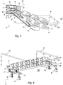
Fig. 3 shows a perspective diagram of some components of the equipment ofFig. 1 ; -
Fig. 4 is a schematic view of other components ofFig. 1 ; -
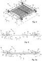
Fig. 5 is a schematic view of further components of the equipment ofFig. 1 ; -
Fig. 6 shows a side diagram of some components of the equipment ofFig. 1 in a given operating condition; -
Fig. 6a represents the side diagram of the components ofFig. 6 in another operating condition; -
Fig. 7 shows a side diagram of some components of the accumulating equipment in accordance with the invention, according to another embodiment and for a given operating condition; -
Fig. 7a is the side diagram ofFig. 7 for another operating condition; -
Fig. 8 shows a side diagram of some components of the equipment according to a variant of the embodiment ofFig. 7 ; -
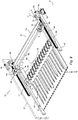
Fig. 9 is a schematic view of further components of the equipment ofFig. 1 ; -
Fig. 10 represents a schematic side section of the equipment ofFig. 1 with evidence of some functional characteristics; -
Fig. 11 shows, on an enlarged scale, details ofFig. 10 in a given operating condition; and -
Fig. 11a represents the details ofFig. 11 in another operating condition. -
Figures 1 ,2 and 2a represent an accumulatingequipment 19 forsheets 20 in accordance with the invention. Theequipment 19 includes aframe 21 with twoside walls front 24 with aninput gate 26 and aback 27 with anoutput gate 28. Through theinput gate 26, theequipment 19 receives thesheets 20 from a feeding apparatus along a feeding direction "F" and, on an accumulating configuration, accumulates the sheets on a stack of accumulatedsheets 29. On a forwarding configuration, theequipment 19 forwards the stack of accumulatedsheets 29, through theoutput gate 28 and along the same direction "F", to a user apparatus for subsequent use. - According to a typical application, the
sheets 20 come from a paper cutter "CM" withoutput rollers 31, while the stack of the accumulatedsheets 29 is forwarded to an "FM" folder withinput rollers 32 for the folding of the stack. - The accumulating
equipment 19 comprises a plurality ofdriving belts 33, anaccumulation plane 34, horizontal in use, for the entering and accumulatingsheets 20, ramp members or "diverters" 36 individually associated with thedriving belts 33, asheet arrest group 37, aforwarding mechanism 38 for the stack of accumulatedsheets 29, acontrol panel 39 and anelectronic control unit 40. Theequipment 19 further comprises sensor elements, not shown, arranged along the path of the sheets and connected to theelectronic unit 40 for counting the sheets in accumulation and detecting some operating conditions and anomalies. - The
driving belts 33 are of the round type (O ring or spaghetti belt), longitudinally elongated and have branches parallel to the feeding direction "F" with axes lying on a geometrical plane perpendicular to theaccumulation plane 34. Specifically, thebelts 33 are stretched betweengrooved input pulleys 41 andgrooved output pulleys 42 and in which respectivelower branches 43 of the belts are arranged a short distance from theplane 34 and define, in the condition of tangency, a geometric plane of movement "GM" for thesheets 20 . - The
pulleys shafts side walls frame 21 in proximity of theinput gate 26 and, respectively, near theoutput gate 28. Theshaft 44 is idle, while theshaft 46 is connected, through a transmission mechanism with belt and pulley (not shown), to amotor 48 for the driving of thepulleys 42 with movement of thelower branches 43 along the direction "F". - The
accumulation plane 34 extends in length between afront edge 49 adjacent to theinput gate 26 and arear edge 51 spaced away from the output gate 28 (Figs. 2b ,4 and6 ). Theaccumulation plane 34 defineslongitudinal slots 52, while theramp members 36 project upwards from theslots 52, above the geometric plane "GM" in an intermediate zone of theplane 34. - The
ramp members 36 each have aninclined surface 56 and astep 57 and define agroove 58 in the upper part. At rest, thelower branches 43 of thedriving belts 33 are freely received in thegrooves 58 of the ramp members and in the condition of tangency with the geometric plane "GM". - According to a known technique, the
sheets 20 entering theequipment 19 are pushed by the output rollers of the external feeding apparatus into the space existing between thelower branches 43 of thedriving belts 33 and theaccumulation plane 34 up to theramp members 36 with consequent lifting of the leading edges of the sheets. Here, with slight deformation, the sheets are engaged by thebranches 43 and dragged along theinclined surfaces 56. The action continues with the passage on theramp members 36 and the dragging of the sheets below the "GM" plane. It occurs into a collection area 59 (seeFig. 2a ) downstream of thestep 57, along theaccumulation plane 34 or on the accumulating sheets. When the trailing edges of the entering sheets leave theramp members 36, thesheets 20 disengage from thebelts 33 and are deposited by jump on theplane 34 or on the accumulating sheets in thecollection area 59. - The sheet arrest group 37operates on the
collection area 59 and is switchable between a closed disposition and an open disposition. Thearrest group 37 is provided for arresting the accumulatingsheets 29 in the closed disposition, and releasing the accumulatedsheets 29 in the open disposition. - For a smooth operation of the
equipment 19, a series ofleaf springs 61 exert a stabilizing action on the accumulating sheets in thecollection area 59. In particular, theleaf springs 61 extend longitudinally above theplane 34 with inclination from top to bottom and each have a free end and an end fixed on acrossbar 62. The leaf springs 61 are interposed between thebelts 33 for the entire width of theaccumulation plane 34, downstream of theramp members 36 and, in the operating conditions, rest lightly with their free ends on the accumulating sheets on a part of theplane 34 adjacent to therear edge 51. - Associated with the
accumulation plane 34 is provided a platform 63 (Figs. 2b and 2c ), which is arranged behind the accumulation plate, slightly below the geometric plane "GM", and completes thecollection area 59. Theplatform 63 crosses theoutput gate 28 and defines an internal section projecting inwards and an external section projecting outward. - The internal section of the
platform 63 has a bevelledfront edge 64, which is arranged in front of theedge 51 of the accumulatingplane 34 and so as to leave a space of separation with respect to theplane 34 and receiving the accumulating sheets. The external section of theplatform 63 accommodates the leading edges of the accumulating sheets, while a bank member of thesheet arrest group 37 in the closed disposition of the arrest group operates on theplatform 63 for defining rearward thecollection area 59 with accurate vertical alignment of the leading edges of the accumulated sheets. - The bank member of the
sheet arrest group 37 is constituted, for example, by arrest lugs 65, which, in the closed disposition of the arrest group, are at a distance "SL" (Fig. 2a ) from thesteps 57 of the ramp members, corresponding to the length of thesheets 20 to be accumulated. Therefore, thecollection area 59 is delimited at the front by thesteps 57 of theramp members 36 on theplane 34 and, at the rear, by thelugs 65 of thearrest group 37 on the external section of theplatform 63. - Specifically, the
sheet arrest group 37 is constituted by alamina 66 with an "L" bend forming the arrest lugs 65, while the external section of theplatform 63 hastransversal openings 67. Thelamina 66 is pivoted on atransversal axis 68 beneath theplatform 63 and in which the "L" bend is directed upwards, while the arrest lugs 65 have the possibility of crossing theopenings 67 of theplatform 63. - The
sheet arrest group 37 can be actuated by anarrest control device 69 between the closed disposition (Fig. 2b ) in which the bank member holds back the accumulating sheets in thecollection area 59 and the open disposition in which the bank member (Fig. 2c ) allows the forwarding of the accumulatedsheets 29. - In the closed disposition of the sheet arrest group 37 (
Fig. 2b ), the arrest lugs 65 cross through theopenings 67 projecting upwards from theplatform 63 and form the rear limit of thecollection area 59 as previously described. In the open disposition of the arrest group 37 (Fig. 2c ), thelugs 65 remain below theplatform 63 and leave a free passage along theplatform 63 for the forwarding of the accumulatedsheets 29 to the external user apparatus. - The
arrest control device 69 comprises a cylindrical actuator 70 (Fig. 2 ) of the pneumatic type, interposed by means of fulcrums at its ends between a bracket formed in an intermediate area of thelamina 66 and a bracket mounted on the rear 27 of theframe 21. On control of theelectronic unit 40, theactuator 70 is actuatable between an extended condition and a retracted condition. The actuator 70 positions the bank member for the closed disposition of thegroup 37 on its extended condition, while positions the bank member for the open disposition of thegroup 37 on its retracted condition. - The
forwarding mechanism 38 includes two series ofmotorized output rollers 71 and 72 (Figs. 2 ,2b ,2c ,3 and 4 ) and a forwardingactuation device 73. Therollers front edge 64 of theplatform 63 and therear edge 51 of theplane 34, respectively above and below the geometric plane "GM". The forwardingactuation device 73 is provided for determining, upon control of theelectronic unit 40, an accumulation arrangement or a forwarding arrangement of theoutput rollers - In the accumulation arrangement of the
rollers Fig. 2b ) of thearrest group 37, a space "G" is formed between therollers belts 33 to accumulate thesheets 20 in thecollection area 59. In the forwarding arrangement, and the open disposition (Fig. 2c ) of thegroup 37, theoutput rollers sheets 29 for their extraction from thecollection area 59 and forwarding them to the user apparatus along the direction "F". It occurs together with a synchronous rotation and in the opposite direction of thesame rollers - The upper output rollers 71 (
Fig. 4 ) are keyed on ashaft 74 rotatably supported and transversely fixed between theside walls frame 21. Thelower output rollers 72 are keyed on ashaft 76 with the possibility of transversal shifting with respect to theshaft 74. To this end, theshaft 76 is rotatably supported between the extremities of twoarms projections arms frame 21 and near theside walls shaft 81 which is rotatably and transversely fixed between theside walls actuation device 73 operates on theprojections arms extremity shaft 76 with respect to theshaft 81. - The motorization of the
output rollers Fig. 3 ) through a transmission chain including atoothed belt 83, aprimary pulley 84, a distributinggroup 86 and two drivenpulleys shafts primary pulley 84 is keyed to an extremity of theshaft 76 and the distributinggroup 86 comprises two drivingpulleys belts pulleys transmission gear wheels gear wheel 94 is rigidly coupled with the drivingpulley 89 while thegear wheel 96 is keyed on theshaft 81. In this way, themotor 82 can impart a synchronous motion and in the opposite direction to theoutput rollers sheets 29. - The forwarding actuation device 73 (
Fig. 4 ) comprises twopneumatic actuators contrasting springs actuators projections springs arms - In the accumulation arrangement of the
rollers actuators projections arms contrasting springs shaft 76 is moved away from theshaft 74 and determines the space "G" between theoutput rollers sheets 20 entering thecollection area 59. - In the forwarding arrangement of the
rollers actuators projections shaft 76 towards theshaft 74. In this way, therollers 72 engage under pressure the accumulatedsheets 29 against the rollers 71 (Fig. 2c ) in the space between theplatform 63 and theplane 34 for the forward of the stack ofsheets 29 as previously described. - The
sheet accumulating equipment 19 also comprises a lamina 101 (Figs. 1 ,2 and2b ), mounted transversely above theoutput gate 28 and with an "L" shaped bent protruding outwards and forming a series oflongitudinal lugs 102. - The
longitudinal lugs 102 are interposed between the arrest lugs 65, are inclined downwards and have respective free ends arranged in front of and at a short distance from the outer section of theplatform 63. Thus, thelongitudinal lugs 102 define, in the forwarding configuration of theequipment 19, an upper guide with stabilization function for the stack ofsheets 29 moving on theplatform 63. - For a reliable accumulation of the
sheets 20 and high operating speed, the height of thestep 57 between the top of theinclined surface 56 of the ramp members 36 (Figs. 2a and6 ) and theaccumulation plane 34, represented with "H", must be included between a minimum value and a maximum value in a rather small range of variation. An insufficient jump would cause stumbling on the underlying sheets and curling up of the entering sheet. An excessive jump would cause the formation of air pockets between the accumulated sheets, creating wrinkles in the stack of sheets forwarded to the user equipment, specifically in the folding executed by the "FM" folder. - In the accumulation arrangement of the
rollers sheets 20 from theramp members 36 with respect to the underlying sheets is progressively reduced depending on the number of sheets already accumulated. The operative limits regarding the minimum value of the jump for the condition of complete accumulation of the sheets and the height "H" for the condition of empty status of the collection area determine the maximum number "N" of the sheets to be accumulated. - The minimum and maximum values of the jumps acceptable by the
ramp members 36 depend significantly on the dimensions and weight of the enteringsheets 20 and on the operating speed of theequipment 19. For sheets larger than A3, average weight between 50 gr/m2 and 80 gr/m2 and speed of the sheets over 100 m/min, a value of the height "H" considered adequate is about 7 to 10 mm. with a reliable accumulation of 2 to 10 enteringsheets 20. - According to the invention, in order to consistently increase the maximum number of accumulable sheets, the
equipment 19 comprises asuspension group 103 and a shiftingcommand mechanism 104 for theaccumulation plane 34. Thesuspension group 103 allows a vertical compensation shifting of the accumulation plane 34 (Figs. 5 and 6 ) with respect to theramp members 36 during the accumulation configuration of theequipment 19, while the shiftingcommand mechanism 104 is actuatable, on control of theelectronic unit 40, for effecting a shifting compensation of theplane 34 according to the number of the accumulatedsheets 20. It can be effected without any shifting of theplatform 64. - For ensuring a regular accumulation of sheets also of large dimensions, the
accumulation plane 34 has a levelled upper surface and a rigid structure. For example, theplane 34 consists of about a 4-6 mm thick plate of steel or aluminium 50 cm wide and 75 cm long and in which thelongitudinal slots 52 are obtained by notching of the plate. - The
plane 34 is supported by aplane frame 106 withlongitudinal beams 107 and cross bars 108. Thelongitudinal beams 107 are arranged inside theframe 21, adjacent to theside walls accumulation plane 34 is fixed on the cross bars 108 and so as to leave a free space between its lateral edges and thelongitudinal beams 107. - In alternative, the
plane 34 can be formed by a series of elongated bars, fixed to the cross bars 108 of theframe 106 and spaced apart from one another so as to define thelongitudinal slots 52. - The
suspension group 103 is of an articulated quadrilateral type, in which theplane 34 is maintained horizontal during its vertical movement. Specifically, thesuspension group 103 comprises fourlever arms 109 pivoted, by means ofpins 111 fixed to theside walls frame 21 and in a condition of adjacency with theside walls lever arms 109 are connected to theplate frame 106 by means ofspherical joints 112 on thelongitudinal beams 107 and by means ofmanual adjustment groups 113 of screw and knob type. Theadjustment groups 113 are interposed between an intermediate section of thelever arms 109 and thejoints 112 and can be manually operated for positioning theplane 34 in a reference position with respect to thearms 109. - The
lever arms 109 have a substantial horizontal arrangement and theaccumulation plane 34 is moved vertically by tilting of a same amount thearms 109. In the field of application of theequipment 19, the compensation shifting of theplane 34 is rather limited. Thelever arms 109 are inclined slightly around the horizontal and cause a very limited component of longitudinal shifting on theaccumulation plane 34. - In the first embodiment of the invention, the accumulation equipment 19 (
Figs. 1 ,2 ,5, 6 and 6a ) is provided for increasing with high reliability, by a given amount, the maximum number "N" of sheets to be accumulated. - For example, for doubling the number of accumulable sheets, with
ramp members 36 of height "H" with respect to theplane 34, after the accumulation of "N" sheets and minimum jump, theplane 34 is lowered by a value "Δc"(SeeFig. 6a ) corresponding to the thickness of the sheets already accumulated. The height "H" is thus restored, to the maximum acceptable jump for the accumulation in optimal conditions, starting from the "N"sheets 20 already accumulated. - The shifting
command mechanism 104 comprises fourpneumatic actuators 114 which operate on thelever arms 109 and can be switched between an extended condition ofFig. 6 and a contracted condition ofFig. 6a for lowering theaccumulation plane 34, starting from its reference positions. Theelectronic control unit 40 counts the accumulatedsheets 20 and activates the switching for the contracted condition and the "Δc" lowering of theplane 34 when "N" accumulated sheets have been reached to proceed with the accumulation up to other "N" sheets . - The
pneumatic actuators 114 are fixed on the outside of thesidewalls respective actuating cylinders 116 connected viapins 117 with one end of thelever arms 109 through corresponding openings of theside walls cylinders 116, between the extended condition and the contracted condition. - The adjustment screws 118 can be operated manually for determining the displacement "Δc" of the
accumulation plane 34. In turn, for positioning theplane 34 at its reference position, themanual adjustment group 113 is operable in the extended condition of thepneumatic actuators 114. - In a second embodiment of the invention, the equipment 19 (
Figs. 7, 7a and 8 ) is carried out in such a way as to keep constant, in the accumulation configuration, the height of the jump of thesheets 20 from theramp members 36 independently of the number of accumulated sheets. In this case, a shift command mechanism, indicated with 121, upon control of anelectronic unit 122, lowers theplane 34 in a progressive manner depending on the number of the previously accumulated sheets. - The
shift command mechanism 121 comprises fourmotion converters 123 operating on thelever arms 109, aservomotor 124 and atransmission group 126 between theconverters 123 and theservomotor 124. - For example, the
motion converters 123 each comprise anut screw 127 and anendless screw 128. Thenut screw 127 is for controlling arespective lever arm 109 while theendless screw 128 is axially fixed and engaged by thenut screw 127 Theservomotor 124 operates directly on the endless screw of one of themotion converters 122 and, via thetransmission group 126, acts on the endless screws of the other motion converters. Thetransmission unit 126 comprises four synchronoustoothed pulleys 129 in rotation with theendless screw 128 and atoothed belt 131 in engagement with thepulleys 129. In this way, the motion from the toothed pulley driven by theservomotor 124 is transmitted to the endless screws of the other converters for a joint control of the fourlever arms 109. - The
electronic control unit 122 counts the accumulatingsheets 20 and incrementally activates theservomotor 124 by rotating theendless screw 128 so as to tilt thelever arms 109 downwards. Theaccumulation plane 34 is thus lowered to keep the height "H" substantially constant, regardless of the thickness "S" (Fig. 7a ) of the accumulated sheets. - The incremental shift of the
plane 34 can be equal to the thickness of asingle sheet 20 but, alternatively, theelectronic unit 122 can activate theservomotor 124 after having counted a predetermined number of pre-accumulated sheets for a lowering of compensation of theplane 34 equal to the overall thickness of the counted sheets. - In a variant of the second embodiment of the invention, the shift command mechanism indicated with 136 (
Fig. 8 ) comprises fourmotion converters 137, which operate on thelever arms 109 by means of the nut screws 127 andendless screw 128 of theconverters 122. In this variant, fourservomotors 138 are used, which operate synchronously and act directly on theendless screws 128. Thelever arms 109 are inclined similarly to the inclinations that can be performed by theservomotor 124 and thetransmission group 126 for a similar lowering of compensation of theaccumulation plane 34. - The transport of the sheets by means of the driving
belts 33 and theramp members 36, of adequate number, ensures an accumulation, without misalignment, of sheets of different width, in particular but not in a limiting way, newspaper sheets to be folded by the following user apparatus. - According to another feature of the invention, the equipment 19 (
Figs. 1 ,9 and10 ) is designed for accumulating enteringsheets 20 of different longitudinal dimensions. For this purpose, theramp members 36 is mounted on asupport carriage 143, which can be shifted longitudinally with respect to thesheet arrest group 37 for changing the length of thecollection area 59 according to the length of the sheets to be accumulated. - With reference to
Figure 9 , for the shifting of thecarriage 143, theequipment 19 comprises tworacks 141 and twoslides 142 sliding on theracks 141, which are connected with thecarriage 143. Theracks 141 are fixed on theside walls frame 21, above thelongitudinal beams 107 of theframe 106. Thecarriage 143 comprises twolateral blocks 144 arranged below theaccumulation plane 34 and supported by theslides 142 through respectivevertical tongues 146 passing through the space between the side edges of theplane 34 and thelongitudinal beams 107 of theframe 106. Theblocks 144 are interconnected by twotransversal bars 147, side by side, parallel to theplane 34. Theramp members 36 are fixed on thebars 147, are in alignment with thelongitudinal slots 52 and protruding from theslots 52 of theplane 34, as above reported. - The
slides 142 rotationally support ashaft 148 on which twopinions 149 and twohandwheels 151 are keyed. Thepinions 149 are in meshing with theracks 141. Thehandwheels 151 can be operated manually for rotating theshaft 148, with shifting of theslides 142 with respect to theracks 141 and shifting of thetongues 146 in the space between theplane 34 and thelongitudinal beams 107. Via thecarriage 143, theramp members 36 can thus be moved along thelongitudinal slots 52 as front demarcation position of thecollection area 59. Two respective locking members with a knob 152 (seeFig. 2 ) can be manually operated for locking theslides 142 on theracks 141 in the selected positions. - As already mentioned, the
sheets 20 entering from theinput gate 26 are pushed by the external power supply equipment, for example the cutter "CM", along the direction "F". The driving belts 33 (Fig. 11 ) overcome this action when the leading edges of the entering sheets reach theramp members 36 and, with the raising, are engaged by thebelts 33. - Moreover, the movement by the feeding apparatus is lost when the trailing edges of the
sheets 20 disengage from the feeding apparatus. This implies that the minimum length of the accumulated sheets must be greater than the distance between the release area of the feeding apparatus, for example that of theoutput rollers 31 for the cutter "CM", and the current position of theramp members 36. - The ramp members 36 (
Figs. 2a and10 ), with their longitudinal position, in addition to determine the front limit of the collectingarea 59, determine the engagement position of thesheet 20 with thebelts 33. In detail, the position of theramp members 36 set for acollection area 59 has a length variable between a minimum value "Lmin" and a maximum value "Lmax", which correspond to the variable distances of the top of theinclined surfaces 56 from theinput gate 26 between a maximum value "Dmax" and a minimum value "Dmin". Therefore, the shorter sheets are collected inarea 59 of length "Lmin", with engagement distance associated to "Dmax", while the longer sheets are collected inarea 59 of length "Lmax", with engagement distance associated to "Dmin". - For reliably accumulating the
longer sheets 20, the distance "Lmax" + "Dmin" between theinput gate 26 and the arrest lugs 65 is high, but the consequent distance "Dmax" associated with the shorter sheets of length "Lmin" is also high. This distance "Dmax" could be greater than that required for the shorter sheets to ensure the engagement of the leading edges with theramp members 36 before leaving the external power supply. The shorter sheets would not enter theequipment 19, with tangling of the sheets coming out of the feeding apparatus. - Conveniently, in accordance with the invention, the
sheet accumulating equipment 19 comprises liftingmembers 156 in an area close to theinput gate 26. The liftingmembers 156 are provided for cooperating with the drivingbelts 33 to begin engagement with the entering sheets and dragging the sheets before the entering sheets reach theramp members 36 and independently of the position of thesame members 36. - According to a non-limiting example, the lifting members 156 (
Fig. 2 ,5 , and10 ) are formed by intermediategrooved wheels 157, arranged near thefront edge 49 of theaccumulation plane 34 and individually associated with thebelts 33. Specifically, thewheels 157 have an upper sector projecting from theslots 52 and a groove which, in the protruding sector, freely accommodates a corresponding portion of thelower branches 43 of thebelts 33. - The
grooved wheels 157 are keyed on a fixedshaft 158 supported below theaccumulation plane 34 by a pair of brackets which are in turn fixed to the lower surface of theplane 34. - The protruding sectors of the
grooved wheels 157 are arranged on the path of thesheets 20 entering along theplane 34 and their distance, indicated by "ED", from the moving elements of the feeding apparatus, for example theoutput rollers 31, must be less than the length of the shorter sheets. In this case, the shorter entering sheets engage thegrooved wheels 157 and are raised towards thebelts 33 before being released by theoutput rollers 31 of the feeding apparatus. - The distance "ID" between the protruding sectors of the
wheels 157 and theramp members 36 in the position "Dmax" must also be less than the length of the shorter sheets, for an engagement of the drivingbelts 33 from thewheels 157 up to theramp members 36. Thus, the smaller of the distances "ED" and "ID" determines the minimum length of thesheets 20 that can be accumulated by theequipment 19. - In a typical application, the
sheet accumulating equipment 19 can accumulate 2-30 sheets, in particular newspapers. Thesheets 20 have a width of 20-50 cm and a length of 20-65 cm with a height of jump "H" of 7-10 mm between the top of theinclined surface 56 and the movement plane "GM" and one compensation shift "Δc" of about 2-3 mm for theaccumulation plane 34. - With the variant of the second embodiment of the invention, the number of sheets to be accumulated can be considerably increased.
- Naturally, the principle of the invention remaining the same, the embodiments and the details of construction of the sheet accumulating equipment may be widely varied with respect to what has been described and illustrated, by way of non-limiting example, without by this departing from the ambit of the present invention.
- As a bank member of the
sheet arrest group 37, in alternative to the arrest lugs 65, a transversal bar can be provided, in contact with theplatform 63 for stopping the sheets in the closed disposition of thegroup 37 and spaced away from the platform for the passage of thesheets 29 in the open disposition of thegroup 37. - With suitable modifications, and when an accurate alignment of the accumulated sheets is not required, the bank member of the
arrest group 37 can be replaced by theoutput rollers equipment 19, or by the pair ofrollers input 32 of the external utilization apparatus and which respectively forward the accumulated sheets and introduce the stack ofsheets 29. Theinput rollers 32 will be modified so as to allow, according to known techniques, a spacing and a pressure adjustment to take into account the thickness of the accumulatedsheets 29. - In the case of arrest by means of the
output rollers equipment 19, therollers sheets 20. For the forwarding configuration, theoutput rollers sheets 29 and are driven for forwarding the stack to the user apparatus. - In the case of arrest by the
input rollers 32 of the output external apparatus, during the accumulation configuration of the equipment 9, theoutput rollers input rollers 32 are in contact each the other and arrest the leading edges of thesheets 20. For the forwarding configuration, both theoutput rollers input rollers 32 engage the stack of accumulatedsheets 29 and are put in motion for the dragging of the stack toward the user apparatus. - Instead of the articulated quadrilateral structure, the suspension group of the
accumulation plane 34 can comprise vertically sliding slides. The compensation shift of the accumulation plate may also have a horizontal component and/or may include an inclination towards the front or rear if deemed appropriate. - As an alternative to the
round drive belts 33, flat belts can be provided with functions similar to those of round belts, as well as instead of pneumatic actuators for moving theaccumulation plane 34 and/or for thearrest control device 69, electromagnetic actuators with similar functions can be provided. - The lifting
members 156 for the accumulation of the shorter sheets can be replaced by thrust pulleys for thelower branches 43 of the drivingbelts 33. The thrust pulleys lead thebranches 43 to slide on theplane 34 or contact corresponding counter-pressure rollers near theinput gate 26 for an early engagement between the drivingbelts 33 and the enteringsheets 20.
Claims (15)
- A sheet accumulating equipment comprising an accumulation plane for sheets entering along a feeding direction, a plurality of driving belts of elongated shape, with respective lower branches positioned in parallel a little above the accumulation plane and ramp members arranged along the path of the sheets and lifting the sheets with engagement with said lower branches and wherein said belts are driven for dragging the lifted sheets with the lower branches and depositing the sheets, by jump, on the accumulation plane or on sheets in accumulation, said accumulating equipment being characterized in that it further comprises
a suspension group for the accumulation plane, a shifting command mechanism and a carriage of support for said ramp members, wherein
said suspension group is provided for allowing a vertical shifting of the accumulation plane with respect to the ramp members so as to modify the height of the jump, and
said shifting command mechanism can be actuated for the vertical shifting of the accumulation plane by adapting the height of the jump according to number and thickness of the accumulated sheets,
said accumulation plane defines a plurality of longitudinal slots, while the ramp members are mounted on said carriage and are partially housed in said longitudinal slots; and
wherein said carriage is longitudinally shiftable for limiting, by means of the ramp members, the longitudinal extension of a sheet gathering area functionally to the length of the sheets to be accumulated. - Sheet accumulating equipment according to claim 1, wherein the ramp members define grooves for accommodating the driving belts, while said belts are tensioned between input grooved pulleys and output grooved pulleys upstream and downstream of the accumulation plane and passage through the grooves of the ramp members, said driving belts are operative for dragging the entering sheets jointly to engagement with the ramp members, and wherein said equipment further comprises lifting members associated individually to the driving belts, said lifting members are arranged between the ramp members and the input grooved pulleys, and wherein the lifting members have a groove housing the lower branches of the belts and are provided for causing said lower branches to engage and drag the entering sheets before the engagement of said sheets with the ramp members.
- Sheet accumulating equipment according to claim 1 or 2 characterized in that it further comprises a sheet arrest group with a bank member and an arrest control device, wherein said arrest control device is provided for actuating the sheet arrest group between a closed disposition in which the bank member arrests leading edges of sheets in accumulation and an open disposition in which the bank member allows an outgoing passage of the accumulated sheets.
- Sheet accumulating equipment according to claim 3 characterized in that it comprises a forwarding mechanism which includes a pair of output rollers and a forward actuation device, wherein said output rollers are arranged upstream and close to the bank member in overlapping condition, respectively above and below the accumulation plane, while the forward actuation device is provided for positioning the output rollers between an accumulation arrangement and a forwarding arrangement, said rollers are separated by a separation space and allow the accumulation of the sheets in the accumulation arrangement and the closed disposition of the bank member, while engage the accumulated sheets in the forwarding arrangement and the open disposition of the bank member and in which said output rollers are driven in synchronism and opposite sense of rotation for output forwarding the accumulated sheets in said forwarding arrangement.
- Sheet accumulating equipment according to claim 4 characterized in that it further comprises a platform, arranged downstream of the accumulation plane, wherein said platform is of partial support for the sheets in accumulation and in which the output rollers are arranged in a space between a front edge of the platform and the rear edge of the supporting plane and in which said bank member operates on said platform.
- Sheet accumulating equipment according to claim 4 characterized in that it further comprises a platform, arranged downstream of the accumulation plane, wherein said platform is of partial support for the sheets in accumulation and defines a series of transversal openings, the bank member includes a series of arrest lugs aligned transversely to the feed direction of the sheets, and wherein said lugs, in the closed disposition of the sheet arrest group, are projecting upwardly from the platform through said transversal openings for arresting the sheets in accumulation and are below the platform in the open disposition of the sheet arrest group for a free passage of the accumulated sheets.
- Sheet accumulating equipment according to one of the preceding claims, characterized in that the suspension group has an articulated quadrilateral structure of connection between the accumulation plane and a frame of the equipment, said quadrilateral structure comprises four lever arms pivoted between the frame and respective end portions of the accumulation plane and wherein said accumulation plane is shiftable by rotations of said lever arms.
- Sheet accumulating equipment according to claim 7, characterized in that said shifting command mechanism comprises four pneumatic actuators and adjusting screws, said pneumatic actuators are operative on the lever arms for two different heights of the jump through the adjustment screws and wherein said adjustment screws can be manually operated to define a reference position of the accumulation plane.
- Sheet accumulating equipment according to one of the preceding claims, characterized in that said shifting command mechanism comprises one or more micro-motors for the vertical shifting of the accumulation plane in accordance with number and thickness of the accumulated sheets so as to optimize the jump of said sheets.
- Sheet accumulating equipment according to one of the preceding claims characterized in that it is used in association with a cutter machine at the input and with a folder machine at the output for 2 to 30 sheets to be accumulated, and in which each sheet has a width of about 20 to 50 cm and a length of about 20 to 70 cm, while the jump has a height of about 7 to 10 mm between the top of the ramp members and a geometric plane tangent to the lower branches of the driving belts.
- Accumulation equipment according to one of the preceding claims characterized in that it further comprises two racks fixedly mounted on sides of the accumulation plane, two slides, connected with the carriage of support for said ramp members and slidably mounted on said racks and two pinions rotatably supported by the slides and meshed with the racks for shifting the support carriage by means of said slides in response to rotation of said pinions.
- Accumulation equipment according to claim 11 characterized in that it further comprises a frame of support for the accumulation plane, wherein said frame includes longitudinal beams and transversal beams, said accumulation plane is fixed on said transversal beams so as to leave two free spaces between the sides of the accumulation plane and the longitudinal beams, and wherein said carriage is connected with the two slides by means of corresponding lugs passing through said free spaces.
- A sheet accumulation equipment comprising a accumulation plane for sheets entering through an input gate along a feeding direction, a plurality of driving belts having longitudinally extended lower branches and positioned in parallel slightly above the accumulation plane, and ramp members arranged along the path of the sheets, wherein said ramp members have a groove for the belts and an inclined surface for lifting the sheets and engaging lifted sheets with the lower branches of the driving belts, said accumulation plane defines or is a portion of a sheet gathering area and the belts are driven for dragging the lifted sheets and depositing the sheets by jump on the sheet gathering area, and said sheet gathering area is limited in front by the ramp members while said ramp members are shiftable according to the longitudinal dimensions of the sheets to be accumulated, said accumulating equipment being characterized in that
the accumulation plane defines a plurality of longitudinal slots partially housing the ramp members, while said the ramp members have a portion protruding upwardly from the accumulation plane;
the ramp members are mounted on a support carriage arranged below the accumulation plane, and having possibility of shifting to define the longitudinal extension of the sheet gathering area, functional to the length of the sheets to be accumulated, and wherein
said accumulation equipment further comprises lifting members arranged between the input gate and the ramp members while said lifting members have a groove housing the lower branches of the driving belts and can be engaged by the entering sheets for causing said lower branches to engage and drag the entering sheets before the engagement of the entering sheets with the ramp members. - Accumulation equipment according to claim 13, further comprising a platform which completes the sheet gathering area, a sheet arrest group with a bank member for rearward delimiting the sheet gathering area and a forwarding mechanism for the accumulated sheets, wherein
the platform is arranged rearward the accumulation plane so as to leave a separation space with the accumulation plane;
the bank member cooperates with the platform and can be actuated between a closed disposition of the arrest group, of arrest for the leading edges of the sheets, and an open disposition of the arrest group for a free passage of the accumulated sheets, and
the forwarding mechanism comprises a pair of output rollers operating in the separation space between the platform and the accumulation plane, and wherein
said output rollers can be positioned between an accumulation configuration with the formation of a gap to allow the accumulation of the sheets in the closed position of the bank member and a forwarding configuration of engagement with the accumulated sheets for forwarding the accumulated sheets in the open disposition of the sheet arrest group. - A sheet accumulation equipment comprising an accumulation plane for sheets entering longitudinally, through an input gate, along a feeding direction, a plurality of driving belts of elongated shape and with lower branches positioned in parallel slightly above the accumulation plane and ramp members arranged along the path of the sheets, in which each of said ramp members has a groove for housing a corresponding lower branch and an inclined plane for lifting the sheets and engaging the sheets with the said lower branches, wherein the accumulation plane defines a sheet gathering area, the belts are provided for dragging the lifted sheets and depositing the sheets by jump onto the gathering area, and wherein the sheet gathering area is limited frontward by the ramp members, while the ramp members can be shifted according to the longitudinal dimensions of the sheets to be accumulated, said equipment being characterized in that it further comprises
a platform which completes the sheet gathering area, a sheet arrest group with a bank member for delimiting rearward the sheet gathering area and a forwarding mechanism for the accumulated sheets, wherein
the platform is arranged rearward said accumulation plane so as to leave a separation space with the accumulation plane;
the bank member cooperates with the platform and can be actuated between a closed disposition of the arrest group, of arrest for the leading edges of the sheets and an open disposition of the arrest group, for the forwarding of the accumulated sheets, and wherein
the forwarding mechanism comprises a pair of output rollers operating in said separation space between the platform and the accumulation plane, and
said output rollers can be positioned between an accumulation configuration with the formation of a space to allow the accumulation of the sheets in the closed position of the bank member and a forwarding configuration of engagement with the accumulated sheets for forwarding the accumulated sheets in the open disposition of the arrest group.
Applications Claiming Priority (1)
| Application Number | Priority Date | Filing Date | Title |
|---|---|---|---|
| IT102018000010572A IT201800010572A1 (en) | 2018-11-26 | 2018-11-26 | SHEET COLLECTION EQUIPMENT |
Publications (2)
| Publication Number | Publication Date |
|---|---|
| EP3659952A1 true EP3659952A1 (en) | 2020-06-03 |
| EP3659952B1 EP3659952B1 (en) | 2023-02-01 |
Family
ID=65767131
Family Applications (1)
| Application Number | Title | Priority Date | Filing Date |
|---|---|---|---|
| EP19211350.4A Active EP3659952B1 (en) | 2018-11-26 | 2019-11-25 | Sheet accumulating equipment |
Country Status (3)
| Country | Link |
|---|---|
| US (1) | US11111099B2 (en) |
| EP (1) | EP3659952B1 (en) |
| IT (1) | IT201800010572A1 (en) |
Citations (10)
| Publication number | Priority date | Publication date | Assignee | Title |
|---|---|---|---|---|
| FR1286181A (en) * | 1961-04-06 | 1962-03-02 | Mueller A G Brugg | Method and device for stacking constantly increasing loads, for example sheets produced in a cutting plant from a strip material |
| US4260148A (en) * | 1979-03-16 | 1981-04-07 | Pako Corporation | Photographic print stacking device |
| US5178379A (en) * | 1991-07-23 | 1993-01-12 | Pitney Bowes Inc. | Sheet collator with alignment apparatus |
| US5411252A (en) * | 1994-04-18 | 1995-05-02 | Pitney Bowes Inc. | Two way adjustable side guide device |
| US5727923A (en) * | 1993-01-27 | 1998-03-17 | Bowe Systec Ag | Collecting device for sheets |
| US5775689A (en) * | 1996-11-22 | 1998-07-07 | Bell & Howell Mail Processing Systems | Accumulator apparatus and method |
| US6227539B1 (en) * | 1998-10-21 | 2001-05-08 | Xerox Corporation | Printer mailboxing system with automatic variable capacity bins |
| US6290226B1 (en) * | 1999-12-23 | 2001-09-18 | Pitney Bowes Inc. | Dual bin envelope supply device and method |
| US7121544B2 (en) | 2004-09-10 | 2006-10-17 | Pitney Bowes Inc. | High throughput sheet accumulator |
| US20100283197A1 (en) * | 2007-08-20 | 2010-11-11 | Lasermax Roll Systems Ab | Arrangement for tacking heets |
Family Cites Families (10)
| Publication number | Priority date | Publication date | Assignee | Title |
|---|---|---|---|---|
| DE3114414C2 (en) * | 1981-04-09 | 1984-08-09 | Jagenberg-Werke AG, 4000 Düsseldorf | Device for stacking sheets |
| US4799663A (en) | 1986-06-26 | 1989-01-24 | G.B.R. Ltd. | Feeding mechanism |
| US4925180A (en) * | 1986-06-26 | 1990-05-15 | Gbr Systems Corporation | Feeding mechanism |
| DE9301072U1 (en) | 1993-01-27 | 1994-06-01 | Böwe Systec AG, 86161 Augsburg | Sheet collecting device for forming sheet stacks |
| US5445368A (en) | 1993-10-27 | 1995-08-29 | Pitney Bowes Inc. | Apparatus and method for forming collations of two different size documents |
| US5484255A (en) | 1994-04-18 | 1996-01-16 | Pitney Bowes Inc. | High capacity, high speed document accumulator |
| US6902162B2 (en) * | 2002-02-12 | 2005-06-07 | Bowe Bell + Howell Company | Non-marking accumulator and related methods |
| US7220312B2 (en) | 2002-03-13 | 2007-05-22 | Micron Technology, Inc. | Methods for treating semiconductor substrates |
| US7523931B2 (en) * | 2006-04-26 | 2009-04-28 | Pitney Bowes Inc. | Forward and reverse media accumulation system |
| US7976019B2 (en) * | 2008-10-21 | 2011-07-12 | Pitney Bowes Inc. | High throughput sheet accumulator |
-
2018
- 2018-11-26 IT IT102018000010572A patent/IT201800010572A1/en unknown
-
2019
- 2019-11-25 EP EP19211350.4A patent/EP3659952B1/en active Active
- 2019-11-25 US US16/694,102 patent/US11111099B2/en active Active
Patent Citations (10)
| Publication number | Priority date | Publication date | Assignee | Title |
|---|---|---|---|---|
| FR1286181A (en) * | 1961-04-06 | 1962-03-02 | Mueller A G Brugg | Method and device for stacking constantly increasing loads, for example sheets produced in a cutting plant from a strip material |
| US4260148A (en) * | 1979-03-16 | 1981-04-07 | Pako Corporation | Photographic print stacking device |
| US5178379A (en) * | 1991-07-23 | 1993-01-12 | Pitney Bowes Inc. | Sheet collator with alignment apparatus |
| US5727923A (en) * | 1993-01-27 | 1998-03-17 | Bowe Systec Ag | Collecting device for sheets |
| US5411252A (en) * | 1994-04-18 | 1995-05-02 | Pitney Bowes Inc. | Two way adjustable side guide device |
| US5775689A (en) * | 1996-11-22 | 1998-07-07 | Bell & Howell Mail Processing Systems | Accumulator apparatus and method |
| US6227539B1 (en) * | 1998-10-21 | 2001-05-08 | Xerox Corporation | Printer mailboxing system with automatic variable capacity bins |
| US6290226B1 (en) * | 1999-12-23 | 2001-09-18 | Pitney Bowes Inc. | Dual bin envelope supply device and method |
| US7121544B2 (en) | 2004-09-10 | 2006-10-17 | Pitney Bowes Inc. | High throughput sheet accumulator |
| US20100283197A1 (en) * | 2007-08-20 | 2010-11-11 | Lasermax Roll Systems Ab | Arrangement for tacking heets |
Also Published As
| Publication number | Publication date |
|---|---|
| US20200165095A1 (en) | 2020-05-28 |
| US11111099B2 (en) | 2021-09-07 |
| IT201800010572A1 (en) | 2020-05-26 |
| EP3659952B1 (en) | 2023-02-01 |
Similar Documents
| Publication | Publication Date | Title |
|---|---|---|
| US4613268A (en) | Process and apparatus for the automatic supply of a machine for processing products in the form of sheets | |
| US5242262A (en) | Process and machine for making batches of sheets from a top of a pile | |
| US4452442A (en) | Device for registering the rear edges of the sheets in sheet delivery mechanisms for printing machines | |
| TWI568574B (en) | Adjustment device and counting discharge device and box machine | |
| GB2127381A (en) | Making gaps in moving streams of sheets | |
| US9085435B2 (en) | Device for stacking sheets of paper or similar | |
| CN111675000A (en) | Paperboard stacking device | |
| US11111099B2 (en) | Sheet accumulation equipment | |
| US8834336B2 (en) | Folding device | |
| US6902162B2 (en) | Non-marking accumulator and related methods | |
| SE450374B (en) | sheet handling | |
| US9290354B2 (en) | Continuous folding process | |
| EP0768260A2 (en) | Paper handling apparatus | |
| US4781510A (en) | Insulation board feeder | |
| AU2009201198A1 (en) | Apparatus for stacking sheet-like products, in particular printed products | |
| US8657097B2 (en) | Squaring-up device for a package converting line | |
| JP3650764B2 (en) | Sorting and conveying device | |
| CN100551796C (en) | conveyor belt device | |
| CN223303861U (en) | Printing connecting line cutting machine stacks branch book mechanism | |
| US20090297322A1 (en) | Stacking device | |
| IT201800010574A1 (en) | ACCUMULATION EQUIPMENT FOR SHEETS OF DIFFERENT SIZES | |
| US5259609A (en) | Blank stacking apparatus | |
| CN212424872U (en) | Paperboard stacking device | |
| EP4108616B1 (en) | Sheet stacking equipment | |
| CA2659652A1 (en) | Apparatus for stacking sheet-like products, in particular printed products |
Legal Events
| Date | Code | Title | Description |
|---|---|---|---|
| PUAI | Public reference made under article 153(3) epc to a published international application that has entered the european phase |
Free format text: ORIGINAL CODE: 0009012 |
|
| STAA | Information on the status of an ep patent application or granted ep patent |
Free format text: STATUS: THE APPLICATION HAS BEEN PUBLISHED |
|
| AK | Designated contracting states |
Kind code of ref document: A1 Designated state(s): AL AT BE BG CH CY CZ DE DK EE ES FI FR GB GR HR HU IE IS IT LI LT LU LV MC MK MT NL NO PL PT RO RS SE SI SK SM TR |
|
| AX | Request for extension of the european patent |
Extension state: BA ME |
|
| STAA | Information on the status of an ep patent application or granted ep patent |
Free format text: STATUS: REQUEST FOR EXAMINATION WAS MADE |
|
| 17P | Request for examination filed |
Effective date: 20201124 |
|
| RBV | Designated contracting states (corrected) |
Designated state(s): AL AT BE BG CH CY CZ DE DK EE ES FI FR GB GR HR HU IE IS IT LI LT LU LV MC MK MT NL NO PL PT RO RS SE SI SK SM TR |
|
| GRAP | Despatch of communication of intention to grant a patent |
Free format text: ORIGINAL CODE: EPIDOSNIGR1 |
|
| STAA | Information on the status of an ep patent application or granted ep patent |
Free format text: STATUS: GRANT OF PATENT IS INTENDED |
|
| INTG | Intention to grant announced |
Effective date: 20220826 |
|
| GRAS | Grant fee paid |
Free format text: ORIGINAL CODE: EPIDOSNIGR3 |
|
| GRAA | (expected) grant |
Free format text: ORIGINAL CODE: 0009210 |
|
| STAA | Information on the status of an ep patent application or granted ep patent |
Free format text: STATUS: THE PATENT HAS BEEN GRANTED |
|
| AK | Designated contracting states |
Kind code of ref document: B1 Designated state(s): AL AT BE BG CH CY CZ DE DK EE ES FI FR GB GR HR HU IE IS IT LI LT LU LV MC MK MT NL NO PL PT RO RS SE SI SK SM TR |
|
| REG | Reference to a national code |
Ref country code: GB Ref legal event code: FG4D |
|
| REG | Reference to a national code |
Ref country code: CH Ref legal event code: EP Ref country code: AT Ref legal event code: REF Ref document number: 1546894 Country of ref document: AT Kind code of ref document: T Effective date: 20230215 |
|
| REG | Reference to a national code |
Ref country code: DE Ref legal event code: R096 Ref document number: 602019024994 Country of ref document: DE |
|
| REG | Reference to a national code |
Ref country code: IE Ref legal event code: FG4D |
|
| REG | Reference to a national code |
Ref country code: LT Ref legal event code: MG9D |
|
| REG | Reference to a national code |
Ref country code: NL Ref legal event code: MP Effective date: 20230201 |
|
| REG | Reference to a national code |
Ref country code: AT Ref legal event code: MK05 Ref document number: 1546894 Country of ref document: AT Kind code of ref document: T Effective date: 20230201 |
|
| PG25 | Lapsed in a contracting state [announced via postgrant information from national office to epo] |
Ref country code: RS Free format text: LAPSE BECAUSE OF FAILURE TO SUBMIT A TRANSLATION OF THE DESCRIPTION OR TO PAY THE FEE WITHIN THE PRESCRIBED TIME-LIMIT Effective date: 20230201 Ref country code: PT Free format text: LAPSE BECAUSE OF FAILURE TO SUBMIT A TRANSLATION OF THE DESCRIPTION OR TO PAY THE FEE WITHIN THE PRESCRIBED TIME-LIMIT Effective date: 20230601 Ref country code: NO Free format text: LAPSE BECAUSE OF FAILURE TO SUBMIT A TRANSLATION OF THE DESCRIPTION OR TO PAY THE FEE WITHIN THE PRESCRIBED TIME-LIMIT Effective date: 20230501 Ref country code: NL Free format text: LAPSE BECAUSE OF FAILURE TO SUBMIT A TRANSLATION OF THE DESCRIPTION OR TO PAY THE FEE WITHIN THE PRESCRIBED TIME-LIMIT Effective date: 20230201 Ref country code: LV Free format text: LAPSE BECAUSE OF FAILURE TO SUBMIT A TRANSLATION OF THE DESCRIPTION OR TO PAY THE FEE WITHIN THE PRESCRIBED TIME-LIMIT Effective date: 20230201 Ref country code: LT Free format text: LAPSE BECAUSE OF FAILURE TO SUBMIT A TRANSLATION OF THE DESCRIPTION OR TO PAY THE FEE WITHIN THE PRESCRIBED TIME-LIMIT Effective date: 20230201 Ref country code: HR Free format text: LAPSE BECAUSE OF FAILURE TO SUBMIT A TRANSLATION OF THE DESCRIPTION OR TO PAY THE FEE WITHIN THE PRESCRIBED TIME-LIMIT Effective date: 20230201 Ref country code: ES Free format text: LAPSE BECAUSE OF FAILURE TO SUBMIT A TRANSLATION OF THE DESCRIPTION OR TO PAY THE FEE WITHIN THE PRESCRIBED TIME-LIMIT Effective date: 20230201 Ref country code: AT Free format text: LAPSE BECAUSE OF FAILURE TO SUBMIT A TRANSLATION OF THE DESCRIPTION OR TO PAY THE FEE WITHIN THE PRESCRIBED TIME-LIMIT Effective date: 20230201 |
|
| PG25 | Lapsed in a contracting state [announced via postgrant information from national office to epo] |
Ref country code: SE Free format text: LAPSE BECAUSE OF FAILURE TO SUBMIT A TRANSLATION OF THE DESCRIPTION OR TO PAY THE FEE WITHIN THE PRESCRIBED TIME-LIMIT Effective date: 20230201 Ref country code: PL Free format text: LAPSE BECAUSE OF FAILURE TO SUBMIT A TRANSLATION OF THE DESCRIPTION OR TO PAY THE FEE WITHIN THE PRESCRIBED TIME-LIMIT Effective date: 20230201 Ref country code: IS Free format text: LAPSE BECAUSE OF FAILURE TO SUBMIT A TRANSLATION OF THE DESCRIPTION OR TO PAY THE FEE WITHIN THE PRESCRIBED TIME-LIMIT Effective date: 20230601 Ref country code: GR Free format text: LAPSE BECAUSE OF FAILURE TO SUBMIT A TRANSLATION OF THE DESCRIPTION OR TO PAY THE FEE WITHIN THE PRESCRIBED TIME-LIMIT Effective date: 20230502 Ref country code: FI Free format text: LAPSE BECAUSE OF FAILURE TO SUBMIT A TRANSLATION OF THE DESCRIPTION OR TO PAY THE FEE WITHIN THE PRESCRIBED TIME-LIMIT Effective date: 20230201 |
|
| PG25 | Lapsed in a contracting state [announced via postgrant information from national office to epo] |
Ref country code: SM Free format text: LAPSE BECAUSE OF FAILURE TO SUBMIT A TRANSLATION OF THE DESCRIPTION OR TO PAY THE FEE WITHIN THE PRESCRIBED TIME-LIMIT Effective date: 20230201 Ref country code: RO Free format text: LAPSE BECAUSE OF FAILURE TO SUBMIT A TRANSLATION OF THE DESCRIPTION OR TO PAY THE FEE WITHIN THE PRESCRIBED TIME-LIMIT Effective date: 20230201 Ref country code: EE Free format text: LAPSE BECAUSE OF FAILURE TO SUBMIT A TRANSLATION OF THE DESCRIPTION OR TO PAY THE FEE WITHIN THE PRESCRIBED TIME-LIMIT Effective date: 20230201 Ref country code: DK Free format text: LAPSE BECAUSE OF FAILURE TO SUBMIT A TRANSLATION OF THE DESCRIPTION OR TO PAY THE FEE WITHIN THE PRESCRIBED TIME-LIMIT Effective date: 20230201 Ref country code: CZ Free format text: LAPSE BECAUSE OF FAILURE TO SUBMIT A TRANSLATION OF THE DESCRIPTION OR TO PAY THE FEE WITHIN THE PRESCRIBED TIME-LIMIT Effective date: 20230201 |
|
| REG | Reference to a national code |
Ref country code: DE Ref legal event code: R097 Ref document number: 602019024994 Country of ref document: DE |
|
| PG25 | Lapsed in a contracting state [announced via postgrant information from national office to epo] |
Ref country code: SK Free format text: LAPSE BECAUSE OF FAILURE TO SUBMIT A TRANSLATION OF THE DESCRIPTION OR TO PAY THE FEE WITHIN THE PRESCRIBED TIME-LIMIT Effective date: 20230201 |
|
| PLBE | No opposition filed within time limit |
Free format text: ORIGINAL CODE: 0009261 |
|
| STAA | Information on the status of an ep patent application or granted ep patent |
Free format text: STATUS: NO OPPOSITION FILED WITHIN TIME LIMIT |
|
| 26N | No opposition filed |
Effective date: 20231103 |
|
| PG25 | Lapsed in a contracting state [announced via postgrant information from national office to epo] |
Ref country code: SI Free format text: LAPSE BECAUSE OF FAILURE TO SUBMIT A TRANSLATION OF THE DESCRIPTION OR TO PAY THE FEE WITHIN THE PRESCRIBED TIME-LIMIT Effective date: 20230201 |
|
| PG25 | Lapsed in a contracting state [announced via postgrant information from national office to epo] |
Ref country code: IT Free format text: LAPSE BECAUSE OF FAILURE TO SUBMIT A TRANSLATION OF THE DESCRIPTION OR TO PAY THE FEE WITHIN THE PRESCRIBED TIME-LIMIT Effective date: 20230201 |
|
| PG25 | Lapsed in a contracting state [announced via postgrant information from national office to epo] |
Ref country code: MC Free format text: LAPSE BECAUSE OF FAILURE TO SUBMIT A TRANSLATION OF THE DESCRIPTION OR TO PAY THE FEE WITHIN THE PRESCRIBED TIME-LIMIT Effective date: 20230201 |
|
| PG25 | Lapsed in a contracting state [announced via postgrant information from national office to epo] |
Ref country code: LU Free format text: LAPSE BECAUSE OF NON-PAYMENT OF DUE FEES Effective date: 20231125 |
|
| PG25 | Lapsed in a contracting state [announced via postgrant information from national office to epo] |
Ref country code: MC Free format text: LAPSE BECAUSE OF FAILURE TO SUBMIT A TRANSLATION OF THE DESCRIPTION OR TO PAY THE FEE WITHIN THE PRESCRIBED TIME-LIMIT Effective date: 20230201 Ref country code: LU Free format text: LAPSE BECAUSE OF NON-PAYMENT OF DUE FEES Effective date: 20231125 |
|
| REG | Reference to a national code |
Ref country code: BE Ref legal event code: MM Effective date: 20231130 |
|
| REG | Reference to a national code |
Ref country code: IE Ref legal event code: MM4A |
|
| PG25 | Lapsed in a contracting state [announced via postgrant information from national office to epo] |
Ref country code: IE Free format text: LAPSE BECAUSE OF NON-PAYMENT OF DUE FEES Effective date: 20231125 |
|
| PG25 | Lapsed in a contracting state [announced via postgrant information from national office to epo] |
Ref country code: BE Free format text: LAPSE BECAUSE OF NON-PAYMENT OF DUE FEES Effective date: 20231130 |
|
| PG25 | Lapsed in a contracting state [announced via postgrant information from national office to epo] |
Ref country code: IE Free format text: LAPSE BECAUSE OF NON-PAYMENT OF DUE FEES Effective date: 20231125 Ref country code: BE Free format text: LAPSE BECAUSE OF NON-PAYMENT OF DUE FEES Effective date: 20231130 |
|
| PG25 | Lapsed in a contracting state [announced via postgrant information from national office to epo] |
Ref country code: BG Free format text: LAPSE BECAUSE OF FAILURE TO SUBMIT A TRANSLATION OF THE DESCRIPTION OR TO PAY THE FEE WITHIN THE PRESCRIBED TIME-LIMIT Effective date: 20230201 |
|
| PG25 | Lapsed in a contracting state [announced via postgrant information from national office to epo] |
Ref country code: BG Free format text: LAPSE BECAUSE OF FAILURE TO SUBMIT A TRANSLATION OF THE DESCRIPTION OR TO PAY THE FEE WITHIN THE PRESCRIBED TIME-LIMIT Effective date: 20230201 |
|
| PG25 | Lapsed in a contracting state [announced via postgrant information from national office to epo] |
Ref country code: CY Free format text: LAPSE BECAUSE OF FAILURE TO SUBMIT A TRANSLATION OF THE DESCRIPTION OR TO PAY THE FEE WITHIN THE PRESCRIBED TIME-LIMIT; INVALID AB INITIO Effective date: 20191125 |
|
| PG25 | Lapsed in a contracting state [announced via postgrant information from national office to epo] |
Ref country code: HU Free format text: LAPSE BECAUSE OF FAILURE TO SUBMIT A TRANSLATION OF THE DESCRIPTION OR TO PAY THE FEE WITHIN THE PRESCRIBED TIME-LIMIT; INVALID AB INITIO Effective date: 20191125 |
|
| REG | Reference to a national code |
Ref country code: CH Ref legal event code: U11 Free format text: ST27 STATUS EVENT CODE: U-0-0-U10-U11 (AS PROVIDED BY THE NATIONAL OFFICE) Effective date: 20251201 |
|
| PG25 | Lapsed in a contracting state [announced via postgrant information from national office to epo] |
Ref country code: TR Free format text: LAPSE BECAUSE OF FAILURE TO SUBMIT A TRANSLATION OF THE DESCRIPTION OR TO PAY THE FEE WITHIN THE PRESCRIBED TIME-LIMIT Effective date: 20230201 |
|
| PGFP | Annual fee paid to national office [announced via postgrant information from national office to epo] |
Ref country code: DE Payment date: 20251128 Year of fee payment: 7 |
|
| PGFP | Annual fee paid to national office [announced via postgrant information from national office to epo] |
Ref country code: GB Payment date: 20251127 Year of fee payment: 7 |
|
| PGFP | Annual fee paid to national office [announced via postgrant information from national office to epo] |
Ref country code: FR Payment date: 20251125 Year of fee payment: 7 |
|
| PGFP | Annual fee paid to national office [announced via postgrant information from national office to epo] |
Ref country code: CH Payment date: 20251201 Year of fee payment: 7 |