EP3659908A1 - Propulsion engine thermal management system - Google Patents
Propulsion engine thermal management system Download PDFInfo
- Publication number
- EP3659908A1 EP3659908A1 EP19206686.8A EP19206686A EP3659908A1 EP 3659908 A1 EP3659908 A1 EP 3659908A1 EP 19206686 A EP19206686 A EP 19206686A EP 3659908 A1 EP3659908 A1 EP 3659908A1
- Authority
- EP
- European Patent Office
- Prior art keywords
- fan
- propulsion engine
- electric machine
- fan blade
- inlet
- Prior art date
- Legal status (The legal status is an assumption and is not a legal conclusion. Google has not performed a legal analysis and makes no representation as to the accuracy of the status listed.)
- Granted
Links
Images




Classifications
-
- B—PERFORMING OPERATIONS; TRANSPORTING
- B64—AIRCRAFT; AVIATION; COSMONAUTICS
- B64C—AEROPLANES; HELICOPTERS
- B64C11/00—Propellers, e.g. of ducted type; Features common to propellers and rotors for rotorcraft
- B64C11/16—Blades
- B64C11/20—Constructional features
- B64C11/24—Hollow blades
-
- B—PERFORMING OPERATIONS; TRANSPORTING
- B64—AIRCRAFT; AVIATION; COSMONAUTICS
- B64D—EQUIPMENT FOR FITTING IN OR TO AIRCRAFT; FLIGHT SUITS; PARACHUTES; ARRANGEMENT OR MOUNTING OF POWER PLANTS OR PROPULSION TRANSMISSIONS IN AIRCRAFT
- B64D27/00—Arrangement or mounting of power plants in aircraft; Aircraft characterised by the type or position of power plants
- B64D27/02—Aircraft characterised by the type or position of power plants
- B64D27/10—Aircraft characterised by the type or position of power plants of gas-turbine type
-
- B—PERFORMING OPERATIONS; TRANSPORTING
- B64—AIRCRAFT; AVIATION; COSMONAUTICS
- B64C—AEROPLANES; HELICOPTERS
- B64C11/00—Propellers, e.g. of ducted type; Features common to propellers and rotors for rotorcraft
- B64C11/16—Blades
-
- B—PERFORMING OPERATIONS; TRANSPORTING
- B64—AIRCRAFT; AVIATION; COSMONAUTICS
- B64D—EQUIPMENT FOR FITTING IN OR TO AIRCRAFT; FLIGHT SUITS; PARACHUTES; ARRANGEMENT OR MOUNTING OF POWER PLANTS OR PROPULSION TRANSMISSIONS IN AIRCRAFT
- B64D13/00—Arrangements or adaptations of air-treatment apparatus for aircraft crew or passengers, or freight space
- B64D13/006—Arrangements or adaptations of air-treatment apparatus for aircraft crew or passengers, or freight space the air being used to cool structural parts of the aircraft
-
- B—PERFORMING OPERATIONS; TRANSPORTING
- B64—AIRCRAFT; AVIATION; COSMONAUTICS
- B64D—EQUIPMENT FOR FITTING IN OR TO AIRCRAFT; FLIGHT SUITS; PARACHUTES; ARRANGEMENT OR MOUNTING OF POWER PLANTS OR PROPULSION TRANSMISSIONS IN AIRCRAFT
- B64D27/00—Arrangement or mounting of power plants in aircraft; Aircraft characterised by the type or position of power plants
- B64D27/02—Aircraft characterised by the type or position of power plants
- B64D27/16—Aircraft characterised by the type or position of power plants of jet type
-
- B—PERFORMING OPERATIONS; TRANSPORTING
- B64—AIRCRAFT; AVIATION; COSMONAUTICS
- B64D—EQUIPMENT FOR FITTING IN OR TO AIRCRAFT; FLIGHT SUITS; PARACHUTES; ARRANGEMENT OR MOUNTING OF POWER PLANTS OR PROPULSION TRANSMISSIONS IN AIRCRAFT
- B64D27/00—Arrangement or mounting of power plants in aircraft; Aircraft characterised by the type or position of power plants
- B64D27/02—Aircraft characterised by the type or position of power plants
- B64D27/30—Aircraft characterised by electric power plants
- B64D27/31—Aircraft characterised by electric power plants within, or attached to, wings
-
- B—PERFORMING OPERATIONS; TRANSPORTING
- B64—AIRCRAFT; AVIATION; COSMONAUTICS
- B64D—EQUIPMENT FOR FITTING IN OR TO AIRCRAFT; FLIGHT SUITS; PARACHUTES; ARRANGEMENT OR MOUNTING OF POWER PLANTS OR PROPULSION TRANSMISSIONS IN AIRCRAFT
- B64D27/00—Arrangement or mounting of power plants in aircraft; Aircraft characterised by the type or position of power plants
- B64D27/02—Aircraft characterised by the type or position of power plants
- B64D27/30—Aircraft characterised by electric power plants
- B64D27/33—Hybrid electric aircraft
-
- B—PERFORMING OPERATIONS; TRANSPORTING
- B64—AIRCRAFT; AVIATION; COSMONAUTICS
- B64D—EQUIPMENT FOR FITTING IN OR TO AIRCRAFT; FLIGHT SUITS; PARACHUTES; ARRANGEMENT OR MOUNTING OF POWER PLANTS OR PROPULSION TRANSMISSIONS IN AIRCRAFT
- B64D33/00—Arrangement in aircraft of power plant parts or auxiliaries not otherwise provided for
- B64D33/08—Arrangement in aircraft of power plant parts or auxiliaries not otherwise provided for of power plant cooling systems
-
- F—MECHANICAL ENGINEERING; LIGHTING; HEATING; WEAPONS; BLASTING
- F04—POSITIVE - DISPLACEMENT MACHINES FOR LIQUIDS; PUMPS FOR LIQUIDS OR ELASTIC FLUIDS
- F04D—NON-POSITIVE-DISPLACEMENT PUMPS
- F04D25/00—Pumping installations or systems
- F04D25/02—Units comprising pumps and their driving means
- F04D25/06—Units comprising pumps and their driving means the pump being electrically driven
-
- F—MECHANICAL ENGINEERING; LIGHTING; HEATING; WEAPONS; BLASTING
- F04—POSITIVE - DISPLACEMENT MACHINES FOR LIQUIDS; PUMPS FOR LIQUIDS OR ELASTIC FLUIDS
- F04D—NON-POSITIVE-DISPLACEMENT PUMPS
- F04D29/00—Details, component parts, or accessories
- F04D29/26—Rotors specially for elastic fluids
- F04D29/32—Rotors specially for elastic fluids for axial flow pumps
- F04D29/321—Rotors specially for elastic fluids for axial flow pumps for axial flow compressors
- F04D29/324—Blades
-
- F—MECHANICAL ENGINEERING; LIGHTING; HEATING; WEAPONS; BLASTING
- F04—POSITIVE - DISPLACEMENT MACHINES FOR LIQUIDS; PUMPS FOR LIQUIDS OR ELASTIC FLUIDS
- F04D—NON-POSITIVE-DISPLACEMENT PUMPS
- F04D29/00—Details, component parts, or accessories
- F04D29/58—Cooling; Heating; Diminishing heat transfer
- F04D29/5806—Cooling the drive system
-
- F—MECHANICAL ENGINEERING; LIGHTING; HEATING; WEAPONS; BLASTING
- F04—POSITIVE - DISPLACEMENT MACHINES FOR LIQUIDS; PUMPS FOR LIQUIDS OR ELASTIC FLUIDS
- F04D—NON-POSITIVE-DISPLACEMENT PUMPS
- F04D29/00—Details, component parts, or accessories
- F04D29/66—Combating cavitation, whirls, noise, vibration or the like; Balancing
- F04D29/68—Combating cavitation, whirls, noise, vibration or the like; Balancing by influencing boundary layers
- F04D29/681—Combating cavitation, whirls, noise, vibration or the like; Balancing by influencing boundary layers especially adapted for elastic fluid pumps
- F04D29/682—Combating cavitation, whirls, noise, vibration or the like; Balancing by influencing boundary layers especially adapted for elastic fluid pumps by fluid extraction
-
- F—MECHANICAL ENGINEERING; LIGHTING; HEATING; WEAPONS; BLASTING
- F04—POSITIVE - DISPLACEMENT MACHINES FOR LIQUIDS; PUMPS FOR LIQUIDS OR ELASTIC FLUIDS
- F04D—NON-POSITIVE-DISPLACEMENT PUMPS
- F04D29/00—Details, component parts, or accessories
- F04D29/66—Combating cavitation, whirls, noise, vibration or the like; Balancing
- F04D29/68—Combating cavitation, whirls, noise, vibration or the like; Balancing by influencing boundary layers
- F04D29/681—Combating cavitation, whirls, noise, vibration or the like; Balancing by influencing boundary layers especially adapted for elastic fluid pumps
- F04D29/684—Combating cavitation, whirls, noise, vibration or the like; Balancing by influencing boundary layers especially adapted for elastic fluid pumps by fluid injection
-
- H—ELECTRICITY
- H02—GENERATION; CONVERSION OR DISTRIBUTION OF ELECTRIC POWER
- H02K—DYNAMO-ELECTRIC MACHINES
- H02K9/00—Arrangements for cooling or ventilating
- H02K9/02—Arrangements for cooling or ventilating by ambient air flowing through the machine
- H02K9/04—Arrangements for cooling or ventilating by ambient air flowing through the machine having means for generating a flow of cooling medium
- H02K9/06—Arrangements for cooling or ventilating by ambient air flowing through the machine having means for generating a flow of cooling medium with fans or impellers driven by the machine shaft
-
- Y—GENERAL TAGGING OF NEW TECHNOLOGICAL DEVELOPMENTS; GENERAL TAGGING OF CROSS-SECTIONAL TECHNOLOGIES SPANNING OVER SEVERAL SECTIONS OF THE IPC; TECHNICAL SUBJECTS COVERED BY FORMER USPC CROSS-REFERENCE ART COLLECTIONS [XRACs] AND DIGESTS
- Y02—TECHNOLOGIES OR APPLICATIONS FOR MITIGATION OR ADAPTATION AGAINST CLIMATE CHANGE
- Y02T—CLIMATE CHANGE MITIGATION TECHNOLOGIES RELATED TO TRANSPORTATION
- Y02T50/00—Aeronautics or air transport
- Y02T50/40—Weight reduction
-
- Y—GENERAL TAGGING OF NEW TECHNOLOGICAL DEVELOPMENTS; GENERAL TAGGING OF CROSS-SECTIONAL TECHNOLOGIES SPANNING OVER SEVERAL SECTIONS OF THE IPC; TECHNICAL SUBJECTS COVERED BY FORMER USPC CROSS-REFERENCE ART COLLECTIONS [XRACs] AND DIGESTS
- Y02—TECHNOLOGIES OR APPLICATIONS FOR MITIGATION OR ADAPTATION AGAINST CLIMATE CHANGE
- Y02T—CLIMATE CHANGE MITIGATION TECHNOLOGIES RELATED TO TRANSPORTATION
- Y02T50/00—Aeronautics or air transport
- Y02T50/60—Efficient propulsion technologies, e.g. for aircraft
Definitions
- the present subject matter relates generally to a propulsion engine for an aeronautical vehicle having a thermal management system, and a propulsion system including one or more of such propulsion engines.
- Distributed electric power propulsion systems for aeronautical vehicles, such as airplanes have been proposed wherein a plurality of electric propulsors are arranged along, e.g., the lengths of the wings of the aircraft and/or at an empennage of the aircraft.
- a central electrical power source may be provided to generate or store electric power, and a distribution bus may distribute the electric power to each of the plurality of electric propulsors.
- Some of these electric propulsion systems may utilize one or more underwing gas turbine engines to generate electric power, or alternatively may have a dedicated turboshaft engine to generate electric power.
- Proposed systems generally utilize a thermal bus circulating a liquid phase thermal fluid to each of the plurality of electric propulsors to gather heat from the plurality of electric propulsors and reject such heat through one or more heat sinks.
- thermal bus circulating a liquid phase thermal fluid to each of the plurality of electric propulsors to gather heat from the plurality of electric propulsors and reject such heat through one or more heat sinks.
- such systems generally require long lengths of conduit, a large amount of thermal transfer fluid, and accessory systems, together adding weight, cost and complication.
- thermal management system for a distributed electric propulsion system having a reduced complexity, weight, and/or cost would be useful.
- a propulsion engine for an aeronautical vehicle defining a radial direction and an air flowpath.
- the propulsion engine includes a power source; and a fan including a fan blade rotatable by the power source and extending generally along the radial direction, the fan blade defining an inlet, an outlet, and an air passage extending between the inlet and the outlet and in airflow communication with the air flowpath, the inlet being positioned inward from the outlet along the radial direction to provide an airflow through the air flowpath.
- the power source is an electric machine including a rotor and a stator, wherein the air flowpath is a cooling air flowpath in thermal communication with the electric machine, and wherein the fan blade is attached to the rotor of the electric machine.
- the fan blade of the fan defines an inner end and an outer end along the radial direction, wherein the inlet is defined at the inner end, and wherein the outlet is defined at the outer end.
- the power source is an electric machine including a rotor and a stator, wherein the inner end of the fan blade is coupled to the rotor of the electric machine, and wherein the fan is configured to induce an airflow through the air flowpath.
- the propulsion engine includes a cowling, wherein the power source is positioned within the cowling, and wherein the inlet of the fan blade is also positioned within the cowling.
- the cowling defines an opening, wherein the air flowpath extends between a first end and a second end, wherein the first end is in airflow communication with the opening of the cowling, and wherein the second end is in airflow communication with the inlet of the fan blade.
- the opening of the cowling is positioned aft of the fan blade of the fan.
- the power source is an electric machine including a rotor and a stator, wherein the air flowpath of the propulsion engine is a cooling air flowpath defined at least in part by the electric machine and is in thermal communication with the stator of the electric machine.
- the power source is an electric machine including a rotor and a stator, wherein the fan blade of the fan defines an inner end and an outer end along the radial direction, wherein the inlet is defined at the inner end, wherein the outlet is defined at the outer end, wherein the outer end of the fan blade is coupled to the rotor of the electric machine, and wherein the fan is configured to provide the airflow to the air flowpath of the electric machine.
- the propulsion engine is an electric fan, and wherein the power source is an electric motor.
- the power source is an electric machine
- the propulsion engine is a gas turbine engine including a fan section and a turbomachine, and wherein the fan section includes the fan and the electric machine.
- the fan blade is a first fan blade of a plurality of fan blades of the fan, wherein each of the plurality of fan blades of the fan defines a respective inlet, a respective outlet, and a respective air passage extending between the respective inlet and outlet, and wherein each of the respective air passages of the plurality of fan blades is in airflow communication with the air flowpath.
- the aeronautical vehicle is an airplane, a helicopter, or an unmanned aeronautical vehicle.
- an aeronautical vehicle in one exemplary embodiment of the present disclosure, includes a fuselage; a wing coupled to and extending from the fuselage; and a propulsion system including one or more propulsion engines coupled to the fuselage, the wing, or both, each of the one or more propulsion engines defining a cooling air flowpath.
- Each of the of the one or more propulsion engines including a power source; and a fan including a fan blade rotatable by the respective power source and extending generally along the radial direction, the fan blade defining an inlet, an outlet, and a cooling air passage extending between the inlet and the outlet and in airflow communication with the respective cooling air flowpath, the inlet being positioned inward from the outlet along the radial direction to provide a cooling airflow through the cooling air flowpath.
- the one or more propulsion engines includes at least two propulsion engines.
- the fan blade of the fan of each propulsion engine defines an inner end and an outer end along the radial direction, wherein the inlet is defined at the inner end, and wherein the outlet is defined at the outer end.
- the inner end of the fan blade is coupled to the power source, and wherein the fan is configured to induce a cooling airflow through the cooling air flowpath.
- each propulsion engine includes a cowling, wherein the power source of each propulsion engine is positioned within the cowling, and wherein the inlet of the fan blade of the fan of each propulsion engine is also positioned within the cowling.
- each propulsion engine defines an opening, wherein the cooling air flowpath of each propulsion engine extends between a first end and a second end, wherein the first end is in airflow communication with the opening of the respective cowling, and wherein the second end is in airflow communication with the inlet of the respective fan blade.
- the fan blade of the fan of each propulsion engine defines an inner end and an outer end along the radial direction, wherein the inlet is defined at the inner end, wherein the outlet is defined at the outer end, wherein the outer end of the fan blade is coupled to the power source of the respective propulsion engine, and wherein the fan of the respective propulsion engine is configured to provide the cooling airflow to the cooling air flowpath of the respective propulsion engine.
- first, second, and third may be used interchangeably to distinguish one component from another and are not intended to signify location or importance of the individual components.
- forward and aft refer to relative positions within an engine or vehicle, and refer to the normal operational attitude of the engine or vehicle. For example, with regard to an engine, forward refers to a position closer to an engine inlet and aft refers to a position closer to an engine nozzle or exhaust.
- upstream and downstream refer to the relative direction with respect to fluid flow in a fluid pathway.
- upstream refers to the direction from which the fluid flows
- downstream refers to the direction to which the fluid flows.
- Coupled refers to both direct coupling, fixing, or attaching, as well as indirect coupling, fixing, or attaching through one or more intermediate components or features, unless otherwise specified herein.
- Approximating language is applied to modify any quantitative representation that could permissibly vary without resulting in a change in the basic function to which it is related. Accordingly, a value modified by a term or terms, such as “about”, “approximately”, and “substantially”, are not to be limited to the precise value specified. In at least some instances, the approximating language may correspond to the precision of an instrument for measuring the value, or the precision of the methods or machines for constructing or manufacturing the components and/or systems. For example, the approximating language may refer to being within a 10 percent margin.
- Fig. 1 provides a top view of an exemplary aircraft 10 as may incorporate various embodiments of the present invention.
- the aircraft 10 defines a longitudinal centerline 14 that extends therethrough, a longitudinal direction L1, a lateral direction L2, a forward end 16, and an aft end 18.
- the aircraft 10 includes a fuselage 12, extending longitudinally from the forward end 16 of the aircraft 10 towards the aft end 18 of the aircraft 10, and a pair of wings 20.
- the first of such wings 20 extends laterally outwardly with respect to the longitudinal centerline 14 from a port side 22 of the fuselage 12 and the second of such wings 20 extends laterally outwardly with respect to the longitudinal centerline 14 from a starboard side 24 of the fuselage 12.
- Each of the wings 20 for the exemplary embodiment depicted includes one or more leading edge flaps 26 and one or more trailing edge flaps 28.
- the aircraft 10 further includes a vertical stabilizer having a rudder flap (not shown) for yaw control, and a pair of horizontal stabilizers 34, each having an elevator flap 36 for pitch control.
- the fuselage 12 additionally includes an outer surface or skin 38. It should be appreciated however, that in other exemplary embodiments of the present disclosure, the aircraft 10 may additionally or alternatively include any other suitable configuration of stabilizer that may or may not extend directly along the vertical direction or horizontal/ lateral direction L2.
- the exemplary aircraft 10 of Fig. 1 additionally includes a propulsion system 100, herein referred to as "system 100".
- the exemplary system 100 includes one or more propulsion engines 102, and more specifically includes a plurality of propulsion engines 102 (such as between two and twenty).
- the embodiment depicted includes a plurality of propulsion engines 102 arranged along each of the pair of wings 20 in an under-wing configuration and a propulsion engine 102 arranged at the aft end 18 of the aircraft 10 in a boundary layer ingestion configuration, such that the propulsion engine 102 is incorporated into or blended with a tail section at the aft end 18.
- the propulsion system 100 further includes a power source 104 and an electrical power distribution bus 106.
- the power source 104 is a central power source configured to generate and/or store electrical power.
- the power source 104 may include one or more gas turbine engines, such as one or more turboshaft engines configured to rotate a respective one or more electric generators. Additionally, or alternatively, the power source 104 may include means for storing electrical power, such as one or more batteries.
- the electrical power distribution bus 106 is electrically coupled to each of the plurality of propulsion engines 102 and the power source 104, such that the electrical power distribution bus 106 may provide electrical power from the power source 104 to each of the plurality of propulsion engines 102.
- the electric propulsion system 100 may be configured in any other suitable manner.
- the propulsion system 100 may have any other suitable number and/or arrangement of propulsion engines 102.
- the one or more propulsion engines 102 may include fixed propulsion engines (such as is shown), rotating propulsion engines (such as in vertical takeoff and landing aircraft), under-wing mounted propulsion engines (such as is shown), propulsion engines housed within the fuselage 12 or wings 20, etc.
- the propulsion system 100 may have any other suitable power source 104.
- the propulsion system 100 may utilize, e.g., one or more underwing-mounted gas turbine engines to generate thrust for the aircraft 10, as well as to drive one or more electric machines to generate electrical power for the electric propulsion engines 102.
- the propulsion system 100 is depicted with an aircraft 10 configured as an airplane, in other embodiments, any other suitable aeronautical vehicle may be used.
- the propulsion system 100 may instead be operable with a helicopter or other vertical takeoff and landing vehicle, an unmanned aeronautical vehicle, etc.
- a propulsion engine 102 for an aeronautical vehicle in accordance with an exemplary embodiment of the present disclosure is depicted.
- the propulsion engine 102 is configured as an electric fan, as will be appreciated from the discussion below.
- the exemplary propulsion engine 102 of Fig. 2 may be incorporated into, e.g., the exemplary propulsion system 100 and aircraft 10 described above with reference to Fig. 1 .
- the propulsion engine 102 of Fig. 2 may be incorporated into any other suitable propulsion system and/or vehicle.
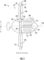
- the propulsion engine 102 defines an axial direction A, a central axis 108 extending along the axial direction A, a radial direction R, and a circumferential direction C. Further, the propulsion engine 102 generally includes an electric machine 110 (which for the embodiment depicted is generally operable as an electric motor), a fan 112, and a cowling 114.
- the electric machine 110 includes a rotor 116 and a stator 118, with the rotor 116 rotatable about the axis 108 in the circumferential direction C relative to the stator 118. Further, the rotor 116 and the stator 118 are enclosed within an electric machine casing 120 for the embodiment shown, and the electric machine casing 120 is enclosed within the cowling 114.
- the electric machine 110 may be configured to receive electrical power from, e.g., a power source of a propulsion system including the exemplary propulsion engine 102 (not shown; see, e.g., power source 104 of propulsion system 100 of Fig. 1 ).
- the electric machine 110 is configured as an "in-runner” electric machine 110, with the rotor 116 positioned radially inward of the stator 118, in other embodiments the electric machine 110 may instead be configured as an "out-runner” electric machine 110, with the rotor 116 position radially outward of the stator 118.
- the electric machine 110 may utilize any suitable electric machine/ electric motor technology.
- the electric machine 110 may be configured as a permanent magnet electric machine, an electromagnet electric machine, an asynchronous electric machine, a synchronous electric machine, an AC electric machine, a DC electric machine , an induction electric machine, a brushed or brushless electric machine, etc.
- the fan 112 generally includes a fan blade 122 attached to the rotor 116 of the electric machine 110 and extending generally along the radial direction R. More specifically, the fan 112 further includes a disk 124 and a fan shaft 126, with the fan blade 122 coupled to the disk 124 and the disk 124 coupled to the fan shaft 126.
- the fan shaft 126 is, in turn, coupled to the rotor 116 of the electric machine 110. In such a manner, rotation of the rotor 116 of the electric machine 110 may correspondingly rotate the fan blade 122 of the fan 112, driving the fan 112 and powering the electric propulsion engine 102.
- the fan blade 122 defines an inner end 128 and an outer end 130 along the radial direction R.
- inner end refers to an inner twenty-five percent (25%) of the fan blade 122 (based on a total span of the fan blade 122)
- outer end refers to an outer twenty-five percent (25%) of the fan blade 122 (again based on the total span of the fan blade 122).
- the electric machine 110 may generate an amount of heat which needs to be at least in part actively rejected to prevent, or minimize a likelihood of, any damage to the propulsion engine 102.
- the propulsion engine 102 defines a cooling air flowpath 132 in thermal communication with the electric machine 110.
- the fan blade 122 of the fan 112 defines an inlet 134, an outlet 136, and a cooling air passage 138 extending between the inlet 134 and the outlet 136 and in airflow communication with the cooling air flowpath 132 of the propulsion engine 102.
- the inlet 134 of the fan blade 122 is positioned inward from the outlet 136 of the fan blades 122 along the radial direction R to provide a cooling airflow 146 (see Fig. 3 ) through the cooling air flowpath 132 of the propulsion engine 102, as will be explained in more detail below. More particularly, for the embodiment shown, the inlet 134 is defined at the inner end 128 of the fan blade 122, within the cowling 114, and the outlet 136 is defined at the outer end 130. However, in other embodiments, the inlet 134 and outlet 136 may be defined at other locations, based on, e.g., an amount of airflow desired through the cooling air flowpath 132, as will also be explained in more detail below.
- the cowling 114 of the exemplary propulsion engine 102 depicted defines an opening 140.
- the opening 140 of the cowling 114 is positioned aft of the fan blade 122 of the fan 112.
- the cowling 114 includes an inlet scoop 142 for directing an airflow 144 from the fan 112 through the opening 140 in the cowling 114 and into the cooling air flowpath 132 as a cooling airflow 146.
- the propulsion engine 102 may include a flow regulation device 145, such as a valve, louvers, or other suitable device, for selectively allowing (or restricting) an airflow through the cooling air flowpath 132.
- the flow regulation device 145 may be operable with a controller for, e.g., restricting airflow through the cooling air flowpath 132 during relatively low power operating modes wherein less heat is required to be rejected from the electric motor 110, which may reduce parasitic pumping losses, as will be appreciated from the discussion below.
- the cowling 114 includes the inlet scoop 142 for the embodiment shown, in other embodiments, the cowling may instead include a grill, louvers, a combination of any of the foregoing, etc.
- the cooling air flowpath 132 of the propulsion engine 102 extends between a first end 148 (i.e., an inlet for the embodiment shown) and a second end 150 (i.e., an outlet for the embodiment shown).
- the first end 148 of the cooling air flowpath 132 is in airflow communication with the opening 140 of the cowling 114, and the second end 150 of the cooling air flowpath 132 is in airflow communication with the inlet 134 of the fan blade 122.
- the cooling air flowpath 132 is in thermal communication with the electric machine 110.
- the cooling air flowpath 132 of the propulsion engine 102 is defined at least in part by the electric machine 110 and is in thermal communication with the stator 118 of the electric machine 110. More specifically, still, for the embodiment shown the cooling air flowpath 132 extends through the electric machine casing 120 and over the stator 118 of the electric machine 110.
- the cowling 114 may define a plurality of openings 140 spaced along the circumferential direction C
- the cooling air flowpath 132 may include a plurality of cooling air flowpaths 132 similarly spaced along the circumferential direction C.
- the propulsion engine 102 includes a stationary to rotating airflow member 152 at the second end 150 of the cooling air flowpath 132 for rotating the cooling airflow 146 in the circumferential direction C (to match the rotation of the fan blade 122) and for providing such cooling airflow 146 to the inlet 134 of the fan blade 122.
- the stationary to rotating airflow member 152 may be an inducer, may include a plurality of stator vanes, and/or may have any other suitable structure.
- the fan blade 122 is a first fan blade 122 of a plurality of fan blades 122 of the fan 112.
- Each of the plurality of fan blades 122 may be spaced generally along the circumferential direction C and attached at a respective inner end 128 to the disk 124.
- Each of the plurality of fan blades 122 of the fan 112 defines a respective inlet 134, a respective outlet 136, and a respective cooling air passage 138 extending between the respective inlet 134 and outlet 136.
- each of the respective cooling air passages 138 of the plurality of fan blades 122 is an airflow communication with the cooling air flowpath 132 of the electric machine 110.
- only certain of the plurality of fan blades 122 of the fan 112 may define the inlet 134, outlet 136, and cooling air passage 138 described.
- the plurality of fan blades 122 may be rotated at a relatively high rotational speed about the axis 108 in the circumferential direction C by the electric machine 110.
- the fan 112 may act as a centrifuging airflow pump, inducing the cooling airflow 146 through the cooling air flowpath 132 (from opening 140), through the inlet 134 and cooling airflow passage 138 to the outlet 136.
- the fan 112 is configured to induce the cooling airflow 146 through the cooling air flowpath 132 of the propulsion engine 102 during operation.
- a cooling of the electric machine 110 during operation of the propulsion engine 102 without requiring a separate liquid thermal transfer fluid-based thermal transfer bus (and associated weight, complication, and/or cost) for the propulsion engine 102, or at least requiring a smaller thermal transfer bus for the propulsion engine 102.
- a lighter overall propulsion system when included as part of, e.g., a distributed electric propulsion system including a multitude of individual electric propulsors.
- each fan blade 122 is defined at the radially outer end 130 and the inlet 134 of each fan blade 122 is defined at the radially inner end 128, in other embodiments, the outlet 136 and/or the inlet 134 may be positioned at any other suitable location so long as the inlet 134 is positioned inward of the outlet 136 along the radial direction R. Varying a separation distance of the inlet 134 and outlet 136 may vary an amount of cooling airflow 146 through the cooling air flowpath 132 of the propulsion engine 102 during operation by varying an amount of delta pressure through the cooling air passages 138. Such may thus vary the amount of cooling of the electric machine 110.
- the propulsion engine 102 may be configured to provide at least about 0.5 pounds per second of cooling airflow 146 through the cooling air passage 138 of each fan blade 122 and up to about five (5) pounds per second of cooling airflow 146 through the cooling air passage 138 of each fan blade 122.
- any other suitable amount of airflow may be provided.
- the propulsion engine 102 may have any other suitable configuration.
- the electric machine 110 is positioned aft/ downstream of the fan 112
- the electric machine 110 may have any other suitable configuration.
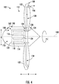
- Fig. 4 a schematic view is provided of a propulsion engine 102 in accordance with another exemplary embodiment of the present disclosure.
- the propulsion engine 102 of Fig. 4 is configured in substantially the same manner as the propulsion engine 102 of Figs. 2 and 3 .
- an electric machine is positioned forward/ upstream of a fan 112 of the propulsion engine 102.
- a first end 148 of a cooling air flowpath 132 is further positioned forward/ upstream of the fan 112, and further is positioned forward of the electric machine 110.
- a propulsion engine 102 in accordance with another exemplary embodiment of the present disclosure is provided.
- the exemplary propulsion engine 102 of Fig. 5 may be configured in substantially the same manner as exemplary propulsion engine 102 of Figs. 2 and 3 .
- the exemplary propulsion engine 102 of Fig. 5 generally includes an electric machine 110 having a rotor 116 and a stator 118, a fan 112 having a fan blade 122 attached to the rotor 116 of the electric machine 110 and extending generally along the radial direction R, and a cowling 114.
- the propulsion engine 102 defines a cooling air flowpath 132 in thermal communication with the electric machine 110, and the fan blade 122 defines an inlet 134, an outlet 136, and a cooling air passage 138 extending between the inlet 134 and the outlet 136, with the cooling air passage 138 being in airflow communication with the cooling air flowpath 132 of the propulsion engine 102.
- the fan blade 122 of the fan 112 is attached to the rotor 116 of the electric machine 110 and extends generally between an inner end 128 and an outer end 130 along the radial direction R.
- the inner end 128 of the fan blade 122 of the fan 112 is at least partially enclosed within the cowling 114.
- the fan blade 122 is not coupled to the rotor 116 of the electric machine 110 at the inner end 128, and instead the outer end 130 of the fan blade 122 is coupled to the rotor 116 of the electric machine 110.
- the electric machine 110 is generally configured as a rim motor.
- the propulsion engine 102 further includes an outer nacelle 154.
- the stator 118 of the electric machine 110 is coupled to, or otherwise positioned within, the outer nacelle 154.
- the rotor 116 of the electric machine 110 is coupled to the outer end 130 of the fan blade 122, or rather, the outer ends 130 of the plurality of fan blades 122 of the fan 112. In such a manner, the electric machine 110 may drive the fan 112 by rotating the outer ends 130 of the plurality of fan blades 122.
- the outlet 136 of the fan blade 122 is again defined at the outer end 130 of the fan blade 122 and the fan 112 is configured to provide a cooling airflow 146 through the cooling air passage 138 to the cooling air flowpath 132 of the electric machine 110.
- the cooling air flowpath 132 extends generally between a first end 148 in airflow communication with a first opening 156 in the outer nacelle 154, aft of the fan blade 122 and aft of the stator 118, to a second end 150 in airflow communication with a second opening 158 in the outer nacelle 154, forward of the fan blade 122 and forward of the stator 118.
- the first and second openings 156, 158 in the outer nacelle 154 are defined on an inside surface 160 of the outer nacelle 154.
- the second opening 158 may instead be defined on an outer surface 162 of the outer nacelle 154 (or elsewhere).
- the cooling air flowpath 132 may extend in any other suitable manner.
- the propulsion engine 102 may be any other suitable propulsion engine 102.
- the propulsion engine 102 may be a gas turbine engine. More specifically, for the embodiment of Fig. 6 , the propulsion engine 102 is configured as a high-bypass turbofan jet engine 200, herein referred to as "turbofan 200.”
- the turbofan 200 defines an axial direction A (extending parallel to a longitudinal centerline 201 provided for reference), a radial direction R, and a circumferential direction (extending about the axial direction A; not depicted in Fig. 6 ).
- the turbofan 200 includes a fan section 202 and a turbomachine 204 disposed downstream from the fan section 202.
- the exemplary turbomachine 204 depicted generally includes a substantially tubular outer casing 206 that defines an annular inlet 208.
- the outer casing 206 encases, in serial flow relationship, a compressor section including a booster or low pressure (LP) compressor 210 and a high pressure (HP) compressor 212; a combustion section 214; a turbine section including a high pressure (HP) turbine 216 and a low pressure (LP) turbine 218; and a jet exhaust nozzle section 220.
- a high pressure (HP) shaft or spool 222 drivingly connects the HP turbine 216 to the HP compressor 212.
- a low pressure (LP) shaft or spool 224 drivingly connects the LP turbine 218 to the LP compressor 210.
- the fan section 202 includes a fan 226 having a plurality of fan blades 228 coupled to a disk 230 in a spaced apart manner.
- the disk 230 is covered by rotatable front hub 236.
- the fan blades 228 extend outwardly from disk 230 generally along the radial direction R.
- the exemplary fan section 202 includes an annular fan casing or outer nacelle 238 that circumferentially surrounds the fan 226 and/or at least a portion of the turbomachine 204.
- the nacelle 238 is supported relative to the turbomachine 204 by a plurality of circumferentially-spaced outlet guide vanes 240.
- the turbofan 200 of Fig. 6 may incorporate aspects of one or more of the exemplary propulsion engines 102 described above with reference to Figs. 2 through 5 .
- the exemplary fan section 202 of the turbofan 200 includes the fan 226 having the respective plurality of fan blades 228.
- the fan 226 of the fan section 202 includes an electric machine 110.
- the electric machine 110 is configured as a rim motor, similar to the exemplary fan 112 and electric machine 110 described above with reference to Fig. 5 .
- the plurality of fan blades 228 of the fan 226 each define a cooling airflow passage 138 extending between an inlet 134 and an outlet 136 and in airflow communication with a cooling air flowpath 132 of the propulsion engine / turbofan 200 (not shown in Fig. 6 ), for providing a cooling airflow to the cooling air flowpath 132 during operation.
- a configuration may therefore provide for cooling of the electric machine 110 during operation of the propulsion engine 102 without requiring separate, relatively complicated thermal management systems for the electric machine 110.
- the electric machine 110 may drive the fan 226 during operation of the turbofan 200.
- the fan 226 may be driven at a different rotational speed than the turbomachine 204, such as the LP shaft 224 of the turbomachine 204.
- the turbomachine 204 such as the LP shaft 224 of the turbomachine 204, may further drive a separate electric machine (operable as an electric generator) for extracting power from the turbomachine 204 and driving the fan 226.
- turbofan engine 200 depicted in Fig. 6 is provided by way of example only, and that in other exemplary embodiments, the turbofan engine 200 may have any other suitable configuration.
- the turbofan engine 200 may be configured as a turboprop engine, a turbojet engine, a differently configured turbofan engine, or any other suitable gas turbine engine.
- the cooling air passage 138 may additionally or alternatively be used to generate a cooling airflow over any other suitable components of a gas turbine engine, an electric propulsion engine, or a combination thereof.
- the cooling air passage 138 may be used to generate a cooling airflow over/through a gearbox, a lubricating oil system, or any other component or system of the gas turbine engine, electric propulsion engine, hybrid electric engine, etc.
- cooling air passage 138 is described as providing a cooling airflow 146 through a cooling air flowpath 132 during operation, in other embodiments, the configurations described herein may not necessarily be used for cooling (e.g., the cooling air passage 138 may simply be an air passage for providing an airflow through an air flowpath). In such an exemplary embodiment, the air passage may be configured for providing air for purposes other than, or in addition to, cooling, such as for anti-icing, for an aircraft system (such as an aircraft cabin system), etc.
Landscapes
- Engineering & Computer Science (AREA)
- Aviation & Aerospace Engineering (AREA)
- Mechanical Engineering (AREA)
- General Engineering & Computer Science (AREA)
- Chemical & Material Sciences (AREA)
- Combustion & Propulsion (AREA)
- Health & Medical Sciences (AREA)
- General Health & Medical Sciences (AREA)
- Pulmonology (AREA)
- Thermal Sciences (AREA)
- Physics & Mathematics (AREA)
- Power Engineering (AREA)
- Structures Of Non-Positive Displacement Pumps (AREA)
- Motor Or Generator Cooling System (AREA)
Abstract
Description
- The present subject matter relates generally to a propulsion engine for an aeronautical vehicle having a thermal management system, and a propulsion system including one or more of such propulsion engines.
- Distributed electric power propulsion systems for aeronautical vehicles, such as airplanes, have been proposed wherein a plurality of electric propulsors are arranged along, e.g., the lengths of the wings of the aircraft and/or at an empennage of the aircraft. A central electrical power source may be provided to generate or store electric power, and a distribution bus may distribute the electric power to each of the plurality of electric propulsors. Some of these electric propulsion systems may utilize one or more underwing gas turbine engines to generate electric power, or alternatively may have a dedicated turboshaft engine to generate electric power.
- Regardless, the electric propulsors generate heat during operation that must be rejected. Proposed systems generally utilize a thermal bus circulating a liquid phase thermal fluid to each of the plurality of electric propulsors to gather heat from the plurality of electric propulsors and reject such heat through one or more heat sinks. However, such systems generally require long lengths of conduit, a large amount of thermal transfer fluid, and accessory systems, together adding weight, cost and complication.
- Accordingly, a thermal management system for a distributed electric propulsion system having a reduced complexity, weight, and/or cost would be useful.
- Aspects and advantages of the invention will be set forth in part in the following description, or may be obvious from the description, or may be learned through practice of the invention.
- In one exemplary embodiment of the present disclosure, a propulsion engine is provided for an aeronautical vehicle defining a radial direction and an air flowpath. The propulsion engine includes a power source; and a fan including a fan blade rotatable by the power source and extending generally along the radial direction, the fan blade defining an inlet, an outlet, and an air passage extending between the inlet and the outlet and in airflow communication with the air flowpath, the inlet being positioned inward from the outlet along the radial direction to provide an airflow through the air flowpath.
- In certain exemplary embodiments the power source is an electric machine including a rotor and a stator, wherein the air flowpath is a cooling air flowpath in thermal communication with the electric machine, and wherein the fan blade is attached to the rotor of the electric machine.
- In certain exemplary embodiments the fan blade of the fan defines an inner end and an outer end along the radial direction, wherein the inlet is defined at the inner end, and wherein the outlet is defined at the outer end.
- For example, in certain exemplary embodiments the power source is an electric machine including a rotor and a stator, wherein the inner end of the fan blade is coupled to the rotor of the electric machine, and wherein the fan is configured to induce an airflow through the air flowpath.
- In certain exemplary embodiments the propulsion engine includes a cowling, wherein the power source is positioned within the cowling, and wherein the inlet of the fan blade is also positioned within the cowling.
- For example, in certain exemplary embodiments the cowling defines an opening, wherein the air flowpath extends between a first end and a second end, wherein the first end is in airflow communication with the opening of the cowling, and wherein the second end is in airflow communication with the inlet of the fan blade.
- For example, in certain exemplary embodiments the opening of the cowling is positioned aft of the fan blade of the fan.
- In certain exemplary embodiments the power source is an electric machine including a rotor and a stator, wherein the air flowpath of the propulsion engine is a cooling air flowpath defined at least in part by the electric machine and is in thermal communication with the stator of the electric machine.
- In certain exemplary embodiments the power source is an electric machine including a rotor and a stator, wherein the fan blade of the fan defines an inner end and an outer end along the radial direction, wherein the inlet is defined at the inner end, wherein the outlet is defined at the outer end, wherein the outer end of the fan blade is coupled to the rotor of the electric machine, and wherein the fan is configured to provide the airflow to the air flowpath of the electric machine.
- In certain exemplary embodiments the propulsion engine is an electric fan, and wherein the power source is an electric motor.
- In certain exemplary embodiments the power source is an electric machine, wherein the propulsion engine is a gas turbine engine including a fan section and a turbomachine, and wherein the fan section includes the fan and the electric machine.
- In certain exemplary embodiments the fan blade is a first fan blade of a plurality of fan blades of the fan, wherein each of the plurality of fan blades of the fan defines a respective inlet, a respective outlet, and a respective air passage extending between the respective inlet and outlet, and wherein each of the respective air passages of the plurality of fan blades is in airflow communication with the air flowpath.
- In certain exemplary embodiments the aeronautical vehicle is an airplane, a helicopter, or an unmanned aeronautical vehicle.
- In one exemplary embodiment of the present disclosure, an aeronautical vehicle is provided. The aeronautical vehicle includes a fuselage; a wing coupled to and extending from the fuselage; and a propulsion system including one or more propulsion engines coupled to the fuselage, the wing, or both, each of the one or more propulsion engines defining a cooling air flowpath. Each of the of the one or more propulsion engines including a power source; and a fan including a fan blade rotatable by the respective power source and extending generally along the radial direction, the fan blade defining an inlet, an outlet, and a cooling air passage extending between the inlet and the outlet and in airflow communication with the respective cooling air flowpath, the inlet being positioned inward from the outlet along the radial direction to provide a cooling airflow through the cooling air flowpath.
- In certain exemplary embodiments the one or more propulsion engines includes at least two propulsion engines.
- In certain exemplary embodiments the fan blade of the fan of each propulsion engine defines an inner end and an outer end along the radial direction, wherein the inlet is defined at the inner end, and wherein the outlet is defined at the outer end.
- For example, in certain exemplary embodiments the inner end of the fan blade is coupled to the power source, and wherein the fan is configured to induce a cooling airflow through the cooling air flowpath.
- In certain exemplary embodiments each propulsion engine includes a cowling, wherein the power source of each propulsion engine is positioned within the cowling, and wherein the inlet of the fan blade of the fan of each propulsion engine is also positioned within the cowling.
- For example, in certain exemplary embodiments the cowling of each propulsion engine defines an opening, wherein the cooling air flowpath of each propulsion engine extends between a first end and a second end, wherein the first end is in airflow communication with the opening of the respective cowling, and wherein the second end is in airflow communication with the inlet of the respective fan blade.
- In certain exemplary embodiments the fan blade of the fan of each propulsion engine defines an inner end and an outer end along the radial direction, wherein the inlet is defined at the inner end, wherein the outlet is defined at the outer end, wherein the outer end of the fan blade is coupled to the power source of the respective propulsion engine, and wherein the fan of the respective propulsion engine is configured to provide the cooling airflow to the cooling air flowpath of the respective propulsion engine.
- These and other features, aspects and advantages of the present invention will become better understood with reference to the following description and appended claims. The accompanying drawings, which are incorporated in and constitute a part of this specification, illustrate embodiments of the invention and, together with the description, serve to explain the principles of the invention.
- A full and enabling disclosure of the present invention, including the best mode thereof, directed to one of ordinary skill in the art, is set forth in the specification, which makes reference to the appended figures, in which:
-
Fig. 1 is a top view of an aircraft according to various exemplary embodiments of the present disclosure. -
Fig. 2 is a side, schematic view of a propulsion engine in accordance with an embodiment of the present disclosure. -
Fig. 3 is a close-up, schematic view of a cooling air flowpath of the propulsion engine ofFig. 2 in accordance with an embodiment of the present disclosure. -
Fig. 4 is a side, schematic view of a propulsion engine in accordance with another embodiment of the present disclosure. -
Fig. 5 is a side, schematic view of a propulsion engine in accordance with yet another embodiment of the present disclosure. -
Fig. 6 is a schematic, cross-sectional view of a gas turbine engine in accordance with an exemplary aspect of the present disclosure. - Reference will now be made in detail to present embodiments of the invention, one or more examples of which are illustrated in the accompanying drawings. The detailed description uses numerical and letter designations to refer to features in the drawings. Like or similar designations in the drawings and description have been used to refer to like or similar parts of the invention.
- The word "exemplary" is used herein to mean "serving as an example, instance, or illustration." Any implementation described herein as "exemplary" is not necessarily to be construed as preferred or advantageous over other implementations.
- As used herein, the terms "first", "second", and "third" may be used interchangeably to distinguish one component from another and are not intended to signify location or importance of the individual components.
- The terms "forward" and "aft" refer to relative positions within an engine or vehicle, and refer to the normal operational attitude of the engine or vehicle. For example, with regard to an engine, forward refers to a position closer to an engine inlet and aft refers to a position closer to an engine nozzle or exhaust.
- The terms "upstream" and "downstream" refer to the relative direction with respect to fluid flow in a fluid pathway. For example, "upstream" refers to the direction from which the fluid flows, and "downstream" refers to the direction to which the fluid flows.
- The terms "coupled," "fixed," "attached to," and the like refer to both direct coupling, fixing, or attaching, as well as indirect coupling, fixing, or attaching through one or more intermediate components or features, unless otherwise specified herein.
- The singular forms "a", "an", and "the" include plural references unless the context clearly dictates otherwise.
- Approximating language, as used herein throughout the specification and claims, is applied to modify any quantitative representation that could permissibly vary without resulting in a change in the basic function to which it is related. Accordingly, a value modified by a term or terms, such as "about", "approximately", and "substantially", are not to be limited to the precise value specified. In at least some instances, the approximating language may correspond to the precision of an instrument for measuring the value, or the precision of the methods or machines for constructing or manufacturing the components and/or systems. For example, the approximating language may refer to being within a 10 percent margin.
- Here and throughout the specification and claims, range limitations are combined and interchanged, such ranges are identified and include all the sub-ranges contained therein unless context or language indicates otherwise. For example, all ranges disclosed herein are inclusive of the endpoints, and the endpoints are independently combinable with each other.
- Referring now to the drawings, wherein identical numerals indicate the same elements throughout the figures,
Fig. 1 provides a top view of anexemplary aircraft 10 as may incorporate various embodiments of the present invention. As shown inFig. 1 , theaircraft 10 defines alongitudinal centerline 14 that extends therethrough, a longitudinal direction L1, a lateral direction L2, aforward end 16, and anaft end 18. Moreover, theaircraft 10 includes afuselage 12, extending longitudinally from theforward end 16 of theaircraft 10 towards theaft end 18 of theaircraft 10, and a pair ofwings 20. The first ofsuch wings 20 extends laterally outwardly with respect to thelongitudinal centerline 14 from aport side 22 of thefuselage 12 and the second ofsuch wings 20 extends laterally outwardly with respect to thelongitudinal centerline 14 from astarboard side 24 of thefuselage 12. Each of thewings 20 for the exemplary embodiment depicted includes one or more leading edge flaps 26 and one or more trailing edge flaps 28. Theaircraft 10 further includes a vertical stabilizer having a rudder flap (not shown) for yaw control, and a pair ofhorizontal stabilizers 34, each having anelevator flap 36 for pitch control. Thefuselage 12 additionally includes an outer surface orskin 38. It should be appreciated however, that in other exemplary embodiments of the present disclosure, theaircraft 10 may additionally or alternatively include any other suitable configuration of stabilizer that may or may not extend directly along the vertical direction or horizontal/ lateral direction L2. - The
exemplary aircraft 10 ofFig. 1 additionally includes apropulsion system 100, herein referred to as "system 100". Theexemplary system 100 includes one ormore propulsion engines 102, and more specifically includes a plurality of propulsion engines 102 (such as between two and twenty). For example, the embodiment depicted includes a plurality ofpropulsion engines 102 arranged along each of the pair ofwings 20 in an under-wing configuration and apropulsion engine 102 arranged at theaft end 18 of theaircraft 10 in a boundary layer ingestion configuration, such that thepropulsion engine 102 is incorporated into or blended with a tail section at theaft end 18. - In addition, the
propulsion system 100 further includes apower source 104 and an electricalpower distribution bus 106. For the embodiment shown, thepower source 104 is a central power source configured to generate and/or store electrical power. For example, thepower source 104 may include one or more gas turbine engines, such as one or more turboshaft engines configured to rotate a respective one or more electric generators. Additionally, or alternatively, thepower source 104 may include means for storing electrical power, such as one or more batteries. The electricalpower distribution bus 106 is electrically coupled to each of the plurality ofpropulsion engines 102 and thepower source 104, such that the electricalpower distribution bus 106 may provide electrical power from thepower source 104 to each of the plurality ofpropulsion engines 102. - It should be appreciated, however, that in other embodiments the
electric propulsion system 100 may be configured in any other suitable manner. For example, in other embodiments, thepropulsion system 100 may have any other suitable number and/or arrangement ofpropulsion engines 102. For example, in other exemplary embodiments, the one ormore propulsion engines 102 may include fixed propulsion engines (such as is shown), rotating propulsion engines (such as in vertical takeoff and landing aircraft), under-wing mounted propulsion engines (such as is shown), propulsion engines housed within thefuselage 12 orwings 20, etc. Further, thepropulsion system 100 may have any othersuitable power source 104. For example, in other embodiments, thepropulsion system 100 may utilize, e.g., one or more underwing-mounted gas turbine engines to generate thrust for theaircraft 10, as well as to drive one or more electric machines to generate electrical power for theelectric propulsion engines 102. Further, although for the embodiment shown thepropulsion system 100 is depicted with anaircraft 10 configured as an airplane, in other embodiments, any other suitable aeronautical vehicle may be used. For example, in other embodiments, thepropulsion system 100 may instead be operable with a helicopter or other vertical takeoff and landing vehicle, an unmanned aeronautical vehicle, etc. - Referring now to
Fig. 2 , apropulsion engine 102 for an aeronautical vehicle in accordance with an exemplary embodiment of the present disclosure is depicted. For the embodiment depicted, thepropulsion engine 102 is configured as an electric fan, as will be appreciated from the discussion below. Theexemplary propulsion engine 102 ofFig. 2 may be incorporated into, e.g., theexemplary propulsion system 100 andaircraft 10 described above with reference toFig. 1 . Alternatively, however, thepropulsion engine 102 ofFig. 2 may be incorporated into any other suitable propulsion system and/or vehicle. - The
propulsion engine 102 defines an axial direction A, acentral axis 108 extending along the axial direction A, a radial direction R, and a circumferential direction C. Further, thepropulsion engine 102 generally includes an electric machine 110 (which for the embodiment depicted is generally operable as an electric motor), afan 112, and acowling 114. - The
electric machine 110 includes arotor 116 and astator 118, with therotor 116 rotatable about theaxis 108 in the circumferential direction C relative to thestator 118. Further, therotor 116 and thestator 118 are enclosed within anelectric machine casing 120 for the embodiment shown, and theelectric machine casing 120 is enclosed within thecowling 114. Theelectric machine 110 may be configured to receive electrical power from, e.g., a power source of a propulsion system including the exemplary propulsion engine 102 (not shown; see, e.g.,power source 104 ofpropulsion system 100 ofFig. 1 ). Further, although for the embodiment shown theelectric machine 110 is configured as an "in-runner"electric machine 110, with therotor 116 positioned radially inward of thestator 118, in other embodiments theelectric machine 110 may instead be configured as an "out-runner"electric machine 110, with therotor 116 position radially outward of thestator 118. Theelectric machine 110 may utilize any suitable electric machine/ electric motor technology. For example, theelectric machine 110 may be configured as a permanent magnet electric machine, an electromagnet electric machine, an asynchronous electric machine, a synchronous electric machine, an AC electric machine, a DC electric machine , an induction electric machine, a brushed or brushless electric machine, etc. - Referring still to
Fig. 2 , thefan 112 generally includes afan blade 122 attached to therotor 116 of theelectric machine 110 and extending generally along the radial direction R. More specifically, thefan 112 further includes adisk 124 and afan shaft 126, with thefan blade 122 coupled to thedisk 124 and thedisk 124 coupled to thefan shaft 126. Thefan shaft 126 is, in turn, coupled to therotor 116 of theelectric machine 110. In such a manner, rotation of therotor 116 of theelectric machine 110 may correspondingly rotate thefan blade 122 of thefan 112, driving thefan 112 and powering theelectric propulsion engine 102. - As will be explained in more detail below, the
fan blade 122 defines aninner end 128 and anouter end 130 along the radial direction R. As used herein, the term "inner end" refers to an inner twenty-five percent (25%) of the fan blade 122 (based on a total span of the fan blade 122), and the term outer "outer end" refers to an outer twenty-five percent (25%) of the fan blade 122 (again based on the total span of the fan blade 122). - As will be appreciated, during operation of the
propulsion engine 102, theelectric machine 110 may generate an amount of heat which needs to be at least in part actively rejected to prevent, or minimize a likelihood of, any damage to thepropulsion engine 102. Accordingly, thepropulsion engine 102 defines a coolingair flowpath 132 in thermal communication with theelectric machine 110. Further, thefan blade 122 of thefan 112 defines aninlet 134, anoutlet 136, and a coolingair passage 138 extending between theinlet 134 and theoutlet 136 and in airflow communication with the coolingair flowpath 132 of thepropulsion engine 102. Theinlet 134 of thefan blade 122 is positioned inward from theoutlet 136 of thefan blades 122 along the radial direction R to provide a cooling airflow 146 (seeFig. 3 ) through the coolingair flowpath 132 of thepropulsion engine 102, as will be explained in more detail below. More particularly, for the embodiment shown, theinlet 134 is defined at theinner end 128 of thefan blade 122, within thecowling 114, and theoutlet 136 is defined at theouter end 130. However, in other embodiments, theinlet 134 andoutlet 136 may be defined at other locations, based on, e.g., an amount of airflow desired through the coolingair flowpath 132, as will also be explained in more detail below. - Referring now also to
Fig. 3 , providing a close-up, schematic view of the coolingair flowpath 132 of theexemplary propulsion engine 102 ofFig. 2 , it will be appreciated that thecowling 114 of theexemplary propulsion engine 102 depicted defines anopening 140. For the embodiment shown, theopening 140 of thecowling 114 is positioned aft of thefan blade 122 of thefan 112. Further, thecowling 114 includes aninlet scoop 142 for directing anairflow 144 from thefan 112 through theopening 140 in thecowling 114 and into the coolingair flowpath 132 as acooling airflow 146. Moreover, as is depicted in phantom, in at least certain exemplary embodiments, thepropulsion engine 102 may include aflow regulation device 145, such as a valve, louvers, or other suitable device, for selectively allowing (or restricting) an airflow through the coolingair flowpath 132. Theflow regulation device 145 may be operable with a controller for, e.g., restricting airflow through the coolingair flowpath 132 during relatively low power operating modes wherein less heat is required to be rejected from theelectric motor 110, which may reduce parasitic pumping losses, as will be appreciated from the discussion below. Further, although thecowling 114 includes theinlet scoop 142 for the embodiment shown, in other embodiments, the cowling may instead include a grill, louvers, a combination of any of the foregoing, etc. - As is also depicted, the cooling
air flowpath 132 of thepropulsion engine 102 extends between a first end 148 (i.e., an inlet for the embodiment shown) and a second end 150 (i.e., an outlet for the embodiment shown). Thefirst end 148 of the coolingair flowpath 132 is in airflow communication with theopening 140 of thecowling 114, and thesecond end 150 of the coolingair flowpath 132 is in airflow communication with theinlet 134 of thefan blade 122. Moreover, as noted above, the coolingair flowpath 132 is in thermal communication with theelectric machine 110. More specifically, for the embodiment shown, the coolingair flowpath 132 of thepropulsion engine 102 is defined at least in part by theelectric machine 110 and is in thermal communication with thestator 118 of theelectric machine 110. More specifically, still, for the embodiment shown the coolingair flowpath 132 extends through theelectric machine casing 120 and over thestator 118 of theelectric machine 110. - Although a
single opening 140 in thecowling 114 and singlecooling air flowpath 132 are depicted, in certain embodiments, thecowling 114 may define a plurality ofopenings 140 spaced along the circumferential direction C, and the coolingair flowpath 132 may include a plurality of coolingair flowpaths 132 similarly spaced along the circumferential direction C. Further, it will be appreciated that thepropulsion engine 102 includes a stationary torotating airflow member 152 at thesecond end 150 of the coolingair flowpath 132 for rotating thecooling airflow 146 in the circumferential direction C (to match the rotation of the fan blade 122) and for providingsuch cooling airflow 146 to theinlet 134 of thefan blade 122. For example, the stationary torotating airflow member 152 may be an inducer, may include a plurality of stator vanes, and/or may have any other suitable structure. - Referring back generally to
Fig. 2 , it will be appreciated that thefan blade 122 is afirst fan blade 122 of a plurality offan blades 122 of thefan 112. Each of the plurality offan blades 122 may be spaced generally along the circumferential direction C and attached at a respectiveinner end 128 to thedisk 124. Each of the plurality offan blades 122 of thefan 112 defines arespective inlet 134, arespective outlet 136, and a respectivecooling air passage 138 extending between therespective inlet 134 andoutlet 136. Further, each of the respectivecooling air passages 138 of the plurality offan blades 122 is an airflow communication with the coolingair flowpath 132 of theelectric machine 110. Notably, however, in other embodiments, only certain of the plurality offan blades 122 of thefan 112 may define theinlet 134,outlet 136, and coolingair passage 138 described. - During operation of the
exemplary propulsion engine 102 depicted inFigs. 2 and3 , the plurality offan blades 122 may be rotated at a relatively high rotational speed about theaxis 108 in the circumferential direction C by theelectric machine 110. Given that theoutlet 136 of eachfan blade 122 is positioned outward from theinlet 134 of eachfan blade 122 along the radial direction R, thefan 112 may act as a centrifuging airflow pump, inducing thecooling airflow 146 through the cooling air flowpath 132 (from opening 140), through theinlet 134 andcooling airflow passage 138 to theoutlet 136. In such a manner, wherein the coolingair flowpath 132 of thepropulsion engine 102 is positioned upstream of the coolingair passages 138 through thefan blades 122, thefan 112 is configured to induce thecooling airflow 146 through the coolingair flowpath 132 of thepropulsion engine 102 during operation. Such may allow for a cooling of theelectric machine 110 during operation of thepropulsion engine 102, without requiring a separate liquid thermal transfer fluid-based thermal transfer bus (and associated weight, complication, and/or cost) for thepropulsion engine 102, or at least requiring a smaller thermal transfer bus for thepropulsion engine 102. Such may allow for a lighter overall propulsion system when included as part of, e.g., a distributed electric propulsion system including a multitude of individual electric propulsors. - As noted above, it will be appreciated that although the
outlet 136 of eachfan blade 122 is defined at the radiallyouter end 130 and theinlet 134 of eachfan blade 122 is defined at the radiallyinner end 128, in other embodiments, theoutlet 136 and/or theinlet 134 may be positioned at any other suitable location so long as theinlet 134 is positioned inward of theoutlet 136 along the radial direction R. Varying a separation distance of theinlet 134 andoutlet 136 may vary an amount ofcooling airflow 146 through the coolingair flowpath 132 of thepropulsion engine 102 during operation by varying an amount of delta pressure through the coolingair passages 138. Such may thus vary the amount of cooling of theelectric machine 110. In one or more these embodiments, thepropulsion engine 102 may be configured to provide at least about 0.5 pounds per second of coolingairflow 146 through the coolingair passage 138 of eachfan blade 122 and up to about five (5) pounds per second of coolingairflow 146 through the coolingair passage 138 of eachfan blade 122. However, in other embodiments, any other suitable amount of airflow may be provided. - It will further be appreciated that in other embodiments of the present disclosure, the
propulsion engine 102 may have any other suitable configuration. For example, although for the embodiment ofFigs. 2 and3 , theelectric machine 110 is positioned aft/ downstream of thefan 112, in other embodiments, theelectric machine 110 may have any other suitable configuration. For example, referring briefly toFig. 4 , a schematic view is provided of apropulsion engine 102 in accordance with another exemplary embodiment of the present disclosure. Thepropulsion engine 102 ofFig. 4 is configured in substantially the same manner as thepropulsion engine 102 ofFigs. 2 and3 . However, for the embodiment ofFig. 4 , an electric machine is positioned forward/ upstream of afan 112 of thepropulsion engine 102. Notably, with such a configuration, afirst end 148 of a coolingair flowpath 132 is further positioned forward/ upstream of thefan 112, and further is positioned forward of theelectric machine 110. - Further, in still other exemplary embodiments, referring now to
Fig. 5 , apropulsion engine 102 in accordance with another exemplary embodiment of the present disclosure is provided. Theexemplary propulsion engine 102 ofFig. 5 may be configured in substantially the same manner asexemplary propulsion engine 102 ofFigs. 2 and3 . - For example, the
exemplary propulsion engine 102 ofFig. 5 generally includes anelectric machine 110 having arotor 116 and astator 118, afan 112 having afan blade 122 attached to therotor 116 of theelectric machine 110 and extending generally along the radial direction R, and acowling 114. Additionally, thepropulsion engine 102 defines a coolingair flowpath 132 in thermal communication with theelectric machine 110, and thefan blade 122 defines aninlet 134, anoutlet 136, and a coolingair passage 138 extending between theinlet 134 and theoutlet 136, with the coolingair passage 138 being in airflow communication with the coolingair flowpath 132 of thepropulsion engine 102. - Further, the
fan blade 122 of thefan 112 is attached to therotor 116 of theelectric machine 110 and extends generally between aninner end 128 and anouter end 130 along the radial direction R. Theinner end 128 of thefan blade 122 of thefan 112 is at least partially enclosed within thecowling 114. However, for the embodiment shown, thefan blade 122 is not coupled to therotor 116 of theelectric machine 110 at theinner end 128, and instead theouter end 130 of thefan blade 122 is coupled to therotor 116 of theelectric machine 110. In such a manner, it will be appreciated that theelectric machine 110 is generally configured as a rim motor. More specifically, for the embodiment shown, thepropulsion engine 102 further includes an outer nacelle 154. Thestator 118 of theelectric machine 110 is coupled to, or otherwise positioned within, the outer nacelle 154. Therotor 116 of theelectric machine 110 is coupled to theouter end 130 of thefan blade 122, or rather, the outer ends 130 of the plurality offan blades 122 of thefan 112. In such a manner, theelectric machine 110 may drive thefan 112 by rotating the outer ends 130 of the plurality offan blades 122. - Notably, with such a configuration, the
outlet 136 of thefan blade 122 is again defined at theouter end 130 of thefan blade 122 and thefan 112 is configured to provide acooling airflow 146 through the coolingair passage 138 to the coolingair flowpath 132 of theelectric machine 110. Notably, the coolingair flowpath 132 extends generally between afirst end 148 in airflow communication with afirst opening 156 in the outer nacelle 154, aft of thefan blade 122 and aft of thestator 118, to asecond end 150 in airflow communication with asecond opening 158 in the outer nacelle 154, forward of thefan blade 122 and forward of thestator 118. The first andsecond openings inside surface 160 of the outer nacelle 154. However, as is depicted in phantom, in other embodiments, thesecond opening 158 may instead be defined on anouter surface 162 of the outer nacelle 154 (or elsewhere). Further, in other embodiments, the coolingair flowpath 132 may extend in any other suitable manner. - It will further be appreciated that in still other exemplary embodiments, the
propulsion engine 102 may be any othersuitable propulsion engine 102. For example, referring now toFig. 6 , thepropulsion engine 102 may be a gas turbine engine. More specifically, for the embodiment ofFig. 6 , thepropulsion engine 102 is configured as a high-bypassturbofan jet engine 200, herein referred to as "turbofan 200." - As shown in
Fig. 6 , theturbofan 200 defines an axial direction A (extending parallel to a longitudinal centerline 201 provided for reference), a radial direction R, and a circumferential direction (extending about the axial direction A; not depicted inFig. 6 ). In general, theturbofan 200 includes a fan section 202 and a turbomachine 204 disposed downstream from the fan section 202. - Briefly, the exemplary turbomachine 204 depicted generally includes a substantially tubular outer casing 206 that defines an annular inlet 208. The outer casing 206 encases, in serial flow relationship, a compressor section including a booster or low pressure (LP) compressor 210 and a high pressure (HP) compressor 212; a combustion section 214; a turbine section including a high pressure (HP) turbine 216 and a low pressure (LP) turbine 218; and a jet exhaust nozzle section 220. A high pressure (HP) shaft or spool 222 drivingly connects the HP turbine 216 to the HP compressor 212. A low pressure (LP) shaft or spool 224 drivingly connects the LP turbine 218 to the LP compressor 210.
- For the embodiment depicted, the fan section 202 includes a fan 226 having a plurality of fan blades 228 coupled to a disk 230 in a spaced apart manner. The disk 230 is covered by rotatable front hub 236. As is depicted, the fan blades 228 extend outwardly from disk 230 generally along the radial direction R. Additionally, the exemplary fan section 202 includes an annular fan casing or outer nacelle 238 that circumferentially surrounds the fan 226 and/or at least a portion of the turbomachine 204. The nacelle 238 is supported relative to the turbomachine 204 by a plurality of circumferentially-spaced outlet guide vanes 240.
- Notably, the
turbofan 200 ofFig. 6 may incorporate aspects of one or more of theexemplary propulsion engines 102 described above with reference toFigs. 2 through 5 . For example, as noted above the exemplary fan section 202 of theturbofan 200 includes the fan 226 having the respective plurality of fan blades 228. Further, the fan 226 of the fan section 202 includes anelectric machine 110. Theelectric machine 110 is configured as a rim motor, similar to theexemplary fan 112 andelectric machine 110 described above with reference toFig. 5 . Additionally, the plurality of fan blades 228 of the fan 226 each define acooling airflow passage 138 extending between aninlet 134 and anoutlet 136 and in airflow communication with a coolingair flowpath 132 of the propulsion engine / turbofan 200 (not shown inFig. 6 ), for providing a cooling airflow to the coolingair flowpath 132 during operation. Such a configuration may therefore provide for cooling of theelectric machine 110 during operation of thepropulsion engine 102 without requiring separate, relatively complicated thermal management systems for theelectric machine 110. - Notably, the
electric machine 110 may drive the fan 226 during operation of theturbofan 200. In such a manner, the fan 226 may be driven at a different rotational speed than the turbomachine 204, such as the LP shaft 224 of the turbomachine 204. Although not depicted, in certain embodiments, the turbomachine 204, such as the LP shaft 224 of the turbomachine 204, may further drive a separate electric machine (operable as an electric generator) for extracting power from the turbomachine 204 and driving the fan 226. - It should be appreciated, however, that the
exemplary turbofan engine 200 depicted inFig. 6 is provided by way of example only, and that in other exemplary embodiments, theturbofan engine 200 may have any other suitable configuration. For example, in other exemplary embodiments, theturbofan engine 200 may be configured as a turboprop engine, a turbojet engine, a differently configured turbofan engine, or any other suitable gas turbine engine. - Moreover, although throughout the present application the cooling
air passage 138 is described as being used to induce a cooling airflow over anelectric machine 110, in other embodiments, the coolingair passage 138 may additionally or alternatively be used to generate a cooling airflow over any other suitable components of a gas turbine engine, an electric propulsion engine, or a combination thereof. For example, the coolingair passage 138 may be used to generate a cooling airflow over/through a gearbox, a lubricating oil system, or any other component or system of the gas turbine engine, electric propulsion engine, hybrid electric engine, etc. - Further, although the cooling
air passage 138 is described as providing acooling airflow 146 through a coolingair flowpath 132 during operation, in other embodiments, the configurations described herein may not necessarily be used for cooling (e.g., the coolingair passage 138 may simply be an air passage for providing an airflow through an air flowpath). In such an exemplary embodiment, the air passage may be configured for providing air for purposes other than, or in addition to, cooling, such as for anti-icing, for an aircraft system (such as an aircraft cabin system), etc. - This written description uses examples to disclose the invention, including the best mode, and also to enable any person skilled in the art to practice the invention, including making and using any devices or systems and performing any incorporated methods. The patentable scope of the invention is defined by the claims, and may include other examples that occur to those skilled in the art. Such other examples are intended to be within the scope of the claims if they include structural elements that do not differ from the literal language of the claims, or if they include equivalent structural elements with insubstantial differences from the literal languages of the claims.
- Further aspects of the invention are provided by the subject matter of the following clauses:
- 1. A propulsion engine for an aeronautical vehicle defining a radial direction and an air flowpath, the propulsion engine comprising:
- a power source; and
- a fan comprising a fan blade rotatable by the power source and extending generally along the radial direction, the fan blade defining an inlet, an outlet, and a air passage extending between the inlet and the outlet and in airflow communication with the air flowpath, the inlet being positioned inward from the outlet along the radial direction to provide an airflow through the air flowpath.
- 2. The propulsion engine of any preceding clause, wherein the power source is an electric machine comprising a rotor and a stator, wherein the air flowpath is a cooling air flowpath in thermal communication with the electric machine, and wherein the fan blade is attached to the rotor of the electric machine.
- 3. The propulsion engine of any preceding clause, wherein the fan blade of the fan defines an inner end and an outer end along the radial direction, wherein the inlet is defined at the inner end, and wherein the outlet is defined at the outer end.
- 4. The propulsion engine of any preceding clause, wherein the power source is an electric machine comprising a rotor and a stator, wherein the inner end of the fan blade is coupled to the rotor of the electric machine, and wherein the fan is configured to induce an airflow through the air flowpath.
- 5. The propulsion engine of any preceding clause, wherein the propulsion engine comprises a cowling, wherein the power source is positioned within the cowling, and wherein the inlet of the fan blade is also positioned within the cowling.
- 6. The propulsion engine of any preceding clause, wherein the cowling defines an opening, wherein the air flowpath extends between a first end and a second end, wherein the first end is in airflow communication with the opening of the cowling, and wherein the second end is in airflow communication with the inlet of the fan blade.
- 7. The propulsion engine of any preceding clause, wherein the opening of the cowling is positioned aft of the fan blade of the fan.
- 8. The propulsion engine of any preceding clause, wherein the power source is an electric machine comprising a rotor and a stator, wherein the air flowpath is a cooling air flowpath of the propulsion engine defined at least in part by the electric machine and is in thermal communication with the stator of the electric machine.
- 9. The propulsion engine of any preceding clause, wherein the power source is an electric machine comprising a rotor and a stator, wherein the fan blade of the fan defines an inner end and an outer end along the radial direction, wherein the inlet is defined at the inner end, wherein the outlet is defined at the outer end, wherein the outer end of the fan blade is coupled to the rotor of the electric machine, and wherein the fan is configured to provide the airflow to the air flowpath of the electric machine.
- 10. The propulsion engine of any preceding clause, wherein the propulsion engine is an electric fan, and wherein the power source is an electric motor.
- 11. The propulsion engine of any preceding clause, wherein the power source is an electric machine, wherein the propulsion engine is a gas turbine engine comprising a fan section and a turbomachine, and wherein the fan section comprises the fan and the electric machine.
- 12. The propulsion engine of any preceding clause, wherein the fan blade is a first fan blade of a plurality of fan blades of the fan, wherein each of the plurality of fan blades of the fan defines a respective inlet, a respective outlet, and a respective air passage extending between the respective inlet and outlet, and wherein each of the respective air passages of the plurality of fan blades is in airflow communication with the air flowpath.
- 13. The propulsion engine of any preceding clause, wherein the aeronautical vehicle is an airplane, a helicopter, or an unmanned aeronautical vehicle.
- 14. An aeronautical vehicle comprising:
- a fuselage;
- a wing coupled to and extending from the fuselage; and
- a propulsion system including one or more propulsion engines coupled to the fuselage, the wing, or both, each of the one or more propulsion engines defining a cooling air flowpath and comprising
- a power source; and
- a fan comprising a fan blade rotatable by the respective power source and extending generally along the radial direction, the fan blade defining an inlet, an outlet, and a cooling air passage extending between the inlet and the outlet and in airflow communication with the respective cooling air flowpath, the inlet being positioned inward from the outlet along the radial direction to provide a cooling airflow through the cooling air flowpath.
- 15. The aeronautical vehicle of any preceding clause, wherein the one or more propulsion engines comprises at least two propulsion engines.
- 16. The aeronautical vehicle of any preceding clause, wherein the fan blade of the fan of each propulsion engine defines an inner end and an outer end along the radial direction, wherein the inlet is defined at the inner end, and wherein the outlet is defined at the outer end.
- 17. The aeronautical vehicle of any preceding clause, wherein the inner end of the fan blade is coupled to the power source, and wherein the fan is configured to induce a cooling airflow through the cooling air flowpath.
- 18. The aeronautical vehicle of any preceding clause, wherein each propulsion engine comprises a cowling, wherein the power source of each propulsion engine is positioned within the cowling, and wherein the inlet of the fan blade of the fan of each propulsion engine is also positioned within the cowling.
- 19. The aeronautical vehicle of any preceding clause, wherein the cowling of each propulsion engine defines an opening, wherein the cooling air flowpath of each propulsion engine extends between a first end and a second end, wherein the first end is in airflow communication with the opening of the respective cowling, and wherein the second end is in airflow communication with the inlet of the respective fan blade.
- 20. The aeronautical vehicle of any preceding clause, wherein the fan blade of the fan of each propulsion engine defines an inner end and an outer end along the radial direction, wherein the inlet is defined at the inner end, wherein the outlet is defined at the outer end, wherein the outer end of the fan blade is coupled to the power source of the respective propulsion engine, and wherein the fan of the respective propulsion engine is configured to provide the cooling airflow to the cooling air flowpath of the respective propulsion engine.
Claims (13)
- A propulsion engine (102) for an aeronautical vehicle defining a radial direction (R) and an air flowpath, the propulsion engine (102) comprising:a power source (104); anda fan (112) comprising a fan blade (122) rotatable by the power source (104) and extending generally along the radial direction (R), the fan blade (122) defining an inlet (134), an outlet (136), and an air passage (138) extending between the inlet (134) and the outlet (136) and in airflow communication with the air flowpath, the inlet (134) being positioned inward from the outlet (136) along the radial direction (R) to provide an airflow through the air flowpath.
- The propulsion engine (102) of claim 1, wherein the power source (104) is an electric machine (110) comprising a rotor (116) and a stator (118), wherein the air flowpath is a cooling air flowpath (132) in thermal communication with the electric machine (110), and wherein the fan blade (122) is attached to the rotor (116) of the electric machine (110).
- The propulsion engine (102) of claim 1 or 2, wherein the fan blade (122) of the fan (112) defines an inner end (128) and an outer end (130) along the radial direction (R), wherein the inlet (134) is defined at the inner end (128), and wherein the outlet (136) is defined at the outer end (130).
- The propulsion engine (102) of claim 3, wherein the power source (104) is an electric machine (110) comprising a rotor (116) and a stator (118), wherein the inner end (128) of the fan blade (122) is coupled to the rotor (116) of the electric machine (110), and wherein the fan (112) is configured to induce the airflow through the air flowpath.
- The propulsion engine (102) of any of claims 1 to 4, wherein the propulsion engine (102) comprises a cowling (114), wherein the power source (104) is positioned within the cowling (114), and wherein the inlet (134) of the fan blade (122) is also positioned within the cowling (114).
- The propulsion engine (102) of claim 5, wherein the cowling (114) defines an opening (140), wherein the air flowpath extends between a first end (148) and a second end (150), wherein the first end (148) is in airflow communication with the opening (140) of the cowling (114), and wherein the second end (150) is in airflow communication with the inlet (134) of the fan blade (122).
- The propulsion engine (102) of claim 6, wherein the opening (140) of the cowling (114) is positioned aft of the fan blade (122) of the fan (112).
- The propulsion engine (102) of any of claims 1 to 7, wherein the power source (104) is an electric machine (110) comprising a rotor (116) and a stator (118), wherein the air flowpath is a cooling air flowpath (132) of the propulsion engine (102) defined at least in part by the electric machine (110) and is in thermal communication with the stator (118) of the electric machine (110).
- The propulsion engine (102) of any of claims 1 to 8, wherein the power source (104) is an electric machine (110) comprising a rotor (116) and a stator (118), wherein the fan blade (122) of the fan (112) defines an inner end (128) and an outer end (130) along the radial direction (R), wherein the inlet (134) is defined at the inner end (128), wherein the outlet (136) is defined at the outer end (130), wherein the outer end (130) of the fan blade (122) is coupled to the rotor (116) of the electric machine (110), and wherein the fan (112) is configured to provide the airflow to the air flowpath of the electric machine (110).
- The propulsion engine (102) of any of claims 1 to 9, wherein the propulsion engine (102) is an electric fan (112), and wherein the power source (104) is an electric motor.
- The propulsion engine (102) of any of claims 1 to 10, wherein the power source (104) is an electric machine (110), wherein the propulsion engine (102) is a gas turbine engine comprising a fan section (202) and a turbomachine (204), and wherein the fan section (202) comprises the fan (112) and the electric machine (110).
- The propulsion engine (102) of any of claims 1 to 11, wherein the fan blade (122) is a first fan blade (122) of a plurality of fan blades (122) of the fan (112), wherein each of the plurality of fan blades (122) of the fan (112) defines a respective inlet (134), a respective outlet (136), and a respective air passage (138) extending between the respective inlet (134) and outlet (136), and wherein each of the respective air passages (138) of the plurality of fan blades (122) is in airflow communication with the air flowpath.
- The propulsion engine (102) of any of claims 1 to 12, wherein the aeronautical vehicle is an airplane, a helicopter, or an unmanned aeronautical vehicle.
Applications Claiming Priority (1)
| Application Number | Priority Date | Filing Date | Title |
|---|---|---|---|
| US16/204,094 US11001389B2 (en) | 2018-11-29 | 2018-11-29 | Propulsion engine thermal management system |
Publications (2)
| Publication Number | Publication Date |
|---|---|
| EP3659908A1 true EP3659908A1 (en) | 2020-06-03 |
| EP3659908B1 EP3659908B1 (en) | 2022-03-30 |
Family
ID=68426178
Family Applications (1)
| Application Number | Title | Priority Date | Filing Date |
|---|---|---|---|
| EP19206686.8A Active EP3659908B1 (en) | 2018-11-29 | 2019-10-31 | Propulsion engine thermal management system |
Country Status (3)
| Country | Link |
|---|---|
| US (1) | US11001389B2 (en) |
| EP (1) | EP3659908B1 (en) |
| CN (1) | CN111232223B (en) |
Families Citing this family (16)
| Publication number | Priority date | Publication date | Assignee | Title |
|---|---|---|---|---|
| US11165309B2 (en) * | 2019-05-10 | 2021-11-02 | Hamilton Sundstrand Corporation | Motor cooling system and method |
| US12012213B2 (en) * | 2020-05-14 | 2024-06-18 | The Penn State Research Foundation | Ice protection for electrically powered rotors |
| CN111894761A (en) * | 2020-07-13 | 2020-11-06 | 潍坊联信增压器股份有限公司 | Centripetal turbofan jet engine |
| PL435035A1 (en) | 2020-08-20 | 2022-02-21 | General Electric Company Polska Spółka Z Ograniczoną Odpowiedzialnością | Gas turbine engines containing embedded electrical machines and associated cooling systems |
| CN112407294B (en) * | 2020-10-30 | 2022-11-22 | 哈尔滨飞机工业集团有限责任公司 | Lubricating oil heat dissipation cabin heating system and method |
| KR20220090243A (en) * | 2020-12-22 | 2022-06-29 | 현대자동차주식회사 | Air mobility |
| JP7443272B2 (en) * | 2021-01-18 | 2024-03-05 | 三菱重工業株式会社 | Fan device and aircraft equipped with the same |
| US12006047B2 (en) * | 2021-06-29 | 2024-06-11 | Flir Unmanned Aerial Systems Ulc | Propeller deicing systems and methods |
| CN115583334A (en) * | 2021-07-05 | 2023-01-10 | 中国航发商用航空发动机有限责任公司 | Thermal management device for BLI fan and propulsion system comprising same |
| JP2023106868A (en) * | 2022-01-21 | 2023-08-02 | 三菱重工業株式会社 | electric propulsion |
| US11965425B2 (en) * | 2022-05-31 | 2024-04-23 | General Electric Company | Airfoil for a turbofan engine |
| CN114991992B (en) * | 2022-06-01 | 2024-10-29 | 中国航空发动机研究院 | Paddle fan structure and engine |
| US11898458B1 (en) * | 2022-08-10 | 2024-02-13 | Hamilton Sundstrand Corporation | Radial fan with leading edge air injection |
| FR3143000A1 (en) * | 2022-12-07 | 2024-06-14 | Safran Helicopter Engines | Propeller for an aircraft propulsion device, propulsion device, aircraft and associated method |
| EP4732359A2 (en) | 2023-06-26 | 2026-04-29 | Tennessee Technological University | Integrated solid oxide fuel cell combustor assembly, system, and method thereof |
| WO2025183725A2 (en) | 2023-08-08 | 2025-09-04 | Tennessee Technological University | Fuel cell turboelectric fan for an aircraft |
Citations (6)
| Publication number | Priority date | Publication date | Assignee | Title |
|---|---|---|---|---|
| US2774552A (en) * | 1955-04-25 | 1956-12-18 | United Aircraft Corp | Helicopter air circulating system |
| EP1159533A1 (en) * | 1999-02-25 | 2001-12-05 | United Technologies Corporation | Centrifugal air flow control |
| EP2390178A2 (en) * | 2010-05-28 | 2011-11-30 | Lockheed Martin Corporation (Maryland Corp.) | Rotor blade having passive bleed path |
| US20120107133A1 (en) * | 2009-05-05 | 2012-05-03 | AIRBUS OPERATIONS (inc, as a Soc. par Act Simpl) | Deicing device for propfan-type propeller blades |
| EP2578803A2 (en) * | 2011-10-07 | 2013-04-10 | General Electric Company | Methods and systems for use in regulating a temperature of components |
| US20180187600A1 (en) * | 2017-01-05 | 2018-07-05 | General Electric Company | Protected core inlet |
Family Cites Families (19)
| Publication number | Priority date | Publication date | Assignee | Title |
|---|---|---|---|---|
| US3575528A (en) | 1968-10-28 | 1971-04-20 | Gen Motors Corp | Turbine rotor cooling |
| US4893987A (en) | 1987-12-08 | 1990-01-16 | General Electric Company | Diffusion-cooled blade tip cap |
| US6004095A (en) * | 1996-06-10 | 1999-12-21 | Massachusetts Institute Of Technology | Reduction of turbomachinery noise |
| US6966174B2 (en) | 2002-04-15 | 2005-11-22 | Paul Marius A | Integrated bypass turbojet engines for air craft and other vehicles |
| US20030192303A1 (en) | 2002-04-15 | 2003-10-16 | Paul Marius A. | Integrated bypass turbojet engines for aircraft and other vehicles |
| KR100622000B1 (en) * | 2004-08-17 | 2006-09-13 | 현대모비스 주식회사 | Cooling fan motor cooling structure of automobile |
| EP1825116A2 (en) | 2004-12-01 | 2007-08-29 | United Technologies Corporation | Ejector cooling of outer case for tip turbine engine |
| US7607286B2 (en) | 2004-12-01 | 2009-10-27 | United Technologies Corporation | Regenerative turbine blade and vane cooling for a tip turbine engine |
| WO2007106059A2 (en) | 2006-02-15 | 2007-09-20 | United Technologies Corporation | Tip turbine engine with aspirated compressor |
| CN101397917A (en) * | 2007-09-28 | 2009-04-01 | 通用电气公司 | Air-cooled bland for turbine |
| US20100083632A1 (en) * | 2008-10-08 | 2010-04-08 | Searete Llc, A Limited Liability Corporation Of The State Of Delaware | Hybrid propulsive engine including at least one independently rotatable compressor rotor |
| US20100162680A1 (en) * | 2008-12-31 | 2010-07-01 | Syed Jalaluddin Khalid | Gas turbine engine with ejector |
| US8459966B2 (en) * | 2010-07-19 | 2013-06-11 | Hamilton Sundstrand Corporation | Ram air fan motor cooling |
| FR2970302B1 (en) * | 2011-01-11 | 2015-07-17 | Snecma | DOUBLE FLOW TURBOREACTOR |
| US9828914B2 (en) * | 2015-04-13 | 2017-11-28 | United Technologies Corporation | Thermal management system and method of circulating air in a gas turbine engine |
| US10107200B2 (en) * | 2015-04-30 | 2018-10-23 | General Electric Company | Turbine engine thermal management |
| US9777633B1 (en) * | 2016-03-30 | 2017-10-03 | General Electric Company | Secondary airflow passage for adjusting airflow distortion in gas turbine engine |
| US10590786B2 (en) * | 2016-05-03 | 2020-03-17 | General Electric Company | System and method for cooling components of a gas turbine engine |
| US11105340B2 (en) * | 2016-08-19 | 2021-08-31 | General Electric Company | Thermal management system for an electric propulsion engine |
-
2018
- 2018-11-29 US US16/204,094 patent/US11001389B2/en active Active
-
2019
- 2019-10-31 EP EP19206686.8A patent/EP3659908B1/en active Active
- 2019-11-28 CN CN201911190315.6A patent/CN111232223B/en active Active
Patent Citations (6)
| Publication number | Priority date | Publication date | Assignee | Title |
|---|---|---|---|---|
| US2774552A (en) * | 1955-04-25 | 1956-12-18 | United Aircraft Corp | Helicopter air circulating system |
| EP1159533A1 (en) * | 1999-02-25 | 2001-12-05 | United Technologies Corporation | Centrifugal air flow control |
| US20120107133A1 (en) * | 2009-05-05 | 2012-05-03 | AIRBUS OPERATIONS (inc, as a Soc. par Act Simpl) | Deicing device for propfan-type propeller blades |
| EP2390178A2 (en) * | 2010-05-28 | 2011-11-30 | Lockheed Martin Corporation (Maryland Corp.) | Rotor blade having passive bleed path |
| EP2578803A2 (en) * | 2011-10-07 | 2013-04-10 | General Electric Company | Methods and systems for use in regulating a temperature of components |
| US20180187600A1 (en) * | 2017-01-05 | 2018-07-05 | General Electric Company | Protected core inlet |
Also Published As
| Publication number | Publication date |
|---|---|
| US11001389B2 (en) | 2021-05-11 |
| CN111232223A (en) | 2020-06-05 |
| CN111232223B (en) | 2023-08-25 |
| EP3659908B1 (en) | 2022-03-30 |
| US20200172259A1 (en) | 2020-06-04 |
Similar Documents
| Publication | Publication Date | Title |
|---|---|---|
| US11001389B2 (en) | Propulsion engine thermal management system | |
| CN107161349B (en) | Propulsion system for aircraft | |
| EP3763623B1 (en) | Propulsion system for an aircraft | |
| CN108725804B (en) | Propulsion system for an aircraft | |
| CN109367794B (en) | propulsion system for aircraft | |
| EP3500748B1 (en) | Propulsion engine for aircraft | |
| EP3500492B1 (en) | Propulsion engine for an aircraft | |
| CA2998931C (en) | Electric propulsion system for an aircraft | |
| EP3421366B1 (en) | Hybrid electric propulsion system for an aircraft | |
| EP3403932B1 (en) | Propulsion system for an aircraft | |
| EP3360783A1 (en) | Propulsion system for an aircraft | |
| EP3421371A1 (en) | Propulsion system for an aircraft | |
| CN114790942A (en) | Embedded motor |
Legal Events
| Date | Code | Title | Description |
|---|---|---|---|
| PUAI | Public reference made under article 153(3) epc to a published international application that has entered the european phase |
Free format text: ORIGINAL CODE: 0009012 |
|
| STAA | Information on the status of an ep patent application or granted ep patent |
Free format text: STATUS: THE APPLICATION HAS BEEN PUBLISHED |
|
| AK | Designated contracting states |
Kind code of ref document: A1 Designated state(s): AL AT BE BG CH CY CZ DE DK EE ES FI FR GB GR HR HU IE IS IT LI LT LU LV MC MK MT NL NO PL PT RO RS SE SI SK SM TR |
|
| AX | Request for extension of the european patent |
Extension state: BA ME |
|
| STAA | Information on the status of an ep patent application or granted ep patent |
Free format text: STATUS: REQUEST FOR EXAMINATION WAS MADE |
|
| 17P | Request for examination filed |
Effective date: 20201120 |
|
| RBV | Designated contracting states (corrected) |
Designated state(s): AL AT BE BG CH CY CZ DE DK EE ES FI FR GB GR HR HU IE IS IT LI LT LU LV MC MK MT NL NO PL PT RO RS SE SI SK SM TR |
|
| GRAP | Despatch of communication of intention to grant a patent |
Free format text: ORIGINAL CODE: EPIDOSNIGR1 |
|
| STAA | Information on the status of an ep patent application or granted ep patent |
Free format text: STATUS: GRANT OF PATENT IS INTENDED |
|
| INTG | Intention to grant announced |
Effective date: 20210506 |
|
| GRAJ | Information related to disapproval of communication of intention to grant by the applicant or resumption of examination proceedings by the epo deleted |
Free format text: ORIGINAL CODE: EPIDOSDIGR1 |
|
| STAA | Information on the status of an ep patent application or granted ep patent |
Free format text: STATUS: REQUEST FOR EXAMINATION WAS MADE |
|
| INTC | Intention to grant announced (deleted) | ||
| GRAP | Despatch of communication of intention to grant a patent |
Free format text: ORIGINAL CODE: EPIDOSNIGR1 |
|
| STAA | Information on the status of an ep patent application or granted ep patent |
Free format text: STATUS: GRANT OF PATENT IS INTENDED |
|
| INTG | Intention to grant announced |
Effective date: 20211018 |
|
| GRAS | Grant fee paid |
Free format text: ORIGINAL CODE: EPIDOSNIGR3 |
|
| GRAA | (expected) grant |
Free format text: ORIGINAL CODE: 0009210 |
|
| STAA | Information on the status of an ep patent application or granted ep patent |
Free format text: STATUS: THE PATENT HAS BEEN GRANTED |
|
| AK | Designated contracting states |
Kind code of ref document: B1 Designated state(s): AL AT BE BG CH CY CZ DE DK EE ES FI FR GB GR HR HU IE IS IT LI LT LU LV MC MK MT NL NO PL PT RO RS SE SI SK SM TR |
|
| REG | Reference to a national code |
Ref country code: GB Ref legal event code: FG4D |
|
| REG | Reference to a national code |
Ref country code: CH Ref legal event code: EP |
|
| REG | Reference to a national code |
Ref country code: DE Ref legal event code: R096 Ref document number: 602019013015 Country of ref document: DE |
|
| REG | Reference to a national code |
Ref country code: AT Ref legal event code: REF Ref document number: 1478971 Country of ref document: AT Kind code of ref document: T Effective date: 20220415 |
|
| REG | Reference to a national code |
Ref country code: IE Ref legal event code: FG4D |
|
| REG | Reference to a national code |
Ref country code: LT Ref legal event code: MG9D |
|
| PG25 | Lapsed in a contracting state [announced via postgrant information from national office to epo] |
Ref country code: SE Free format text: LAPSE BECAUSE OF FAILURE TO SUBMIT A TRANSLATION OF THE DESCRIPTION OR TO PAY THE FEE WITHIN THE PRESCRIBED TIME-LIMIT Effective date: 20220330 Ref country code: RS Free format text: LAPSE BECAUSE OF FAILURE TO SUBMIT A TRANSLATION OF THE DESCRIPTION OR TO PAY THE FEE WITHIN THE PRESCRIBED TIME-LIMIT Effective date: 20220330 Ref country code: NO Free format text: LAPSE BECAUSE OF FAILURE TO SUBMIT A TRANSLATION OF THE DESCRIPTION OR TO PAY THE FEE WITHIN THE PRESCRIBED TIME-LIMIT Effective date: 20220630 Ref country code: LT Free format text: LAPSE BECAUSE OF FAILURE TO SUBMIT A TRANSLATION OF THE DESCRIPTION OR TO PAY THE FEE WITHIN THE PRESCRIBED TIME-LIMIT Effective date: 20220330 Ref country code: HR Free format text: LAPSE BECAUSE OF FAILURE TO SUBMIT A TRANSLATION OF THE DESCRIPTION OR TO PAY THE FEE WITHIN THE PRESCRIBED TIME-LIMIT Effective date: 20220330 Ref country code: BG Free format text: LAPSE BECAUSE OF FAILURE TO SUBMIT A TRANSLATION OF THE DESCRIPTION OR TO PAY THE FEE WITHIN THE PRESCRIBED TIME-LIMIT Effective date: 20220630 |
|
| REG | Reference to a national code |
Ref country code: NL Ref legal event code: MP Effective date: 20220330 |
|
| REG | Reference to a national code |
Ref country code: AT Ref legal event code: MK05 Ref document number: 1478971 Country of ref document: AT Kind code of ref document: T Effective date: 20220330 |
|
| PG25 | Lapsed in a contracting state [announced via postgrant information from national office to epo] |
Ref country code: LV Free format text: LAPSE BECAUSE OF FAILURE TO SUBMIT A TRANSLATION OF THE DESCRIPTION OR TO PAY THE FEE WITHIN THE PRESCRIBED TIME-LIMIT Effective date: 20220330 Ref country code: GR Free format text: LAPSE BECAUSE OF FAILURE TO SUBMIT A TRANSLATION OF THE DESCRIPTION OR TO PAY THE FEE WITHIN THE PRESCRIBED TIME-LIMIT Effective date: 20220701 Ref country code: FI Free format text: LAPSE BECAUSE OF FAILURE TO SUBMIT A TRANSLATION OF THE DESCRIPTION OR TO PAY THE FEE WITHIN THE PRESCRIBED TIME-LIMIT Effective date: 20220330 |
|
| PG25 | Lapsed in a contracting state [announced via postgrant information from national office to epo] |
Ref country code: NL Free format text: LAPSE BECAUSE OF FAILURE TO SUBMIT A TRANSLATION OF THE DESCRIPTION OR TO PAY THE FEE WITHIN THE PRESCRIBED TIME-LIMIT Effective date: 20220330 |
|
| PG25 | Lapsed in a contracting state [announced via postgrant information from national office to epo] |
Ref country code: SM Free format text: LAPSE BECAUSE OF FAILURE TO SUBMIT A TRANSLATION OF THE DESCRIPTION OR TO PAY THE FEE WITHIN THE PRESCRIBED TIME-LIMIT Effective date: 20220330 Ref country code: SK Free format text: LAPSE BECAUSE OF FAILURE TO SUBMIT A TRANSLATION OF THE DESCRIPTION OR TO PAY THE FEE WITHIN THE PRESCRIBED TIME-LIMIT Effective date: 20220330 Ref country code: RO Free format text: LAPSE BECAUSE OF FAILURE TO SUBMIT A TRANSLATION OF THE DESCRIPTION OR TO PAY THE FEE WITHIN THE PRESCRIBED TIME-LIMIT Effective date: 20220330 Ref country code: PT Free format text: LAPSE BECAUSE OF FAILURE TO SUBMIT A TRANSLATION OF THE DESCRIPTION OR TO PAY THE FEE WITHIN THE PRESCRIBED TIME-LIMIT Effective date: 20220801 Ref country code: ES Free format text: LAPSE BECAUSE OF FAILURE TO SUBMIT A TRANSLATION OF THE DESCRIPTION OR TO PAY THE FEE WITHIN THE PRESCRIBED TIME-LIMIT Effective date: 20220330 Ref country code: EE Free format text: LAPSE BECAUSE OF FAILURE TO SUBMIT A TRANSLATION OF THE DESCRIPTION OR TO PAY THE FEE WITHIN THE PRESCRIBED TIME-LIMIT Effective date: 20220330 Ref country code: CZ Free format text: LAPSE BECAUSE OF FAILURE TO SUBMIT A TRANSLATION OF THE DESCRIPTION OR TO PAY THE FEE WITHIN THE PRESCRIBED TIME-LIMIT Effective date: 20220330 Ref country code: AT Free format text: LAPSE BECAUSE OF FAILURE TO SUBMIT A TRANSLATION OF THE DESCRIPTION OR TO PAY THE FEE WITHIN THE PRESCRIBED TIME-LIMIT Effective date: 20220330 |
|
| PG25 | Lapsed in a contracting state [announced via postgrant information from national office to epo] |
Ref country code: PL Free format text: LAPSE BECAUSE OF FAILURE TO SUBMIT A TRANSLATION OF THE DESCRIPTION OR TO PAY THE FEE WITHIN THE PRESCRIBED TIME-LIMIT Effective date: 20220330 Ref country code: IS Free format text: LAPSE BECAUSE OF FAILURE TO SUBMIT A TRANSLATION OF THE DESCRIPTION OR TO PAY THE FEE WITHIN THE PRESCRIBED TIME-LIMIT Effective date: 20220730 Ref country code: AL Free format text: LAPSE BECAUSE OF FAILURE TO SUBMIT A TRANSLATION OF THE DESCRIPTION OR TO PAY THE FEE WITHIN THE PRESCRIBED TIME-LIMIT Effective date: 20220330 |
|
| REG | Reference to a national code |
Ref country code: DE Ref legal event code: R097 Ref document number: 602019013015 Country of ref document: DE |
|
| PG25 | Lapsed in a contracting state [announced via postgrant information from national office to epo] |
Ref country code: DK Free format text: LAPSE BECAUSE OF FAILURE TO SUBMIT A TRANSLATION OF THE DESCRIPTION OR TO PAY THE FEE WITHIN THE PRESCRIBED TIME-LIMIT Effective date: 20220330 |
|
| PLBE | No opposition filed within time limit |
Free format text: ORIGINAL CODE: 0009261 |
|
| STAA | Information on the status of an ep patent application or granted ep patent |
Free format text: STATUS: NO OPPOSITION FILED WITHIN TIME LIMIT |
|
| 26N | No opposition filed |
Effective date: 20230103 |
|
| PG25 | Lapsed in a contracting state [announced via postgrant information from national office to epo] |
Ref country code: SI Free format text: LAPSE BECAUSE OF FAILURE TO SUBMIT A TRANSLATION OF THE DESCRIPTION OR TO PAY THE FEE WITHIN THE PRESCRIBED TIME-LIMIT Effective date: 20220330 Ref country code: MC Free format text: LAPSE BECAUSE OF FAILURE TO SUBMIT A TRANSLATION OF THE DESCRIPTION OR TO PAY THE FEE WITHIN THE PRESCRIBED TIME-LIMIT Effective date: 20220330 |
|
| REG | Reference to a national code |
Ref country code: CH Ref legal event code: PL |
|
| P01 | Opt-out of the competence of the unified patent court (upc) registered |
Effective date: 20230411 |
|
| REG | Reference to a national code |
Ref country code: BE Ref legal event code: MM Effective date: 20221031 |
|
| PG25 | Lapsed in a contracting state [announced via postgrant information from national office to epo] |
Ref country code: LU Free format text: LAPSE BECAUSE OF NON-PAYMENT OF DUE FEES Effective date: 20221031 |
|
| PG25 | Lapsed in a contracting state [announced via postgrant information from national office to epo] |
Ref country code: LI Free format text: LAPSE BECAUSE OF NON-PAYMENT OF DUE FEES Effective date: 20221031 Ref country code: IT Free format text: LAPSE BECAUSE OF FAILURE TO SUBMIT A TRANSLATION OF THE DESCRIPTION OR TO PAY THE FEE WITHIN THE PRESCRIBED TIME-LIMIT Effective date: 20220330 Ref country code: CH Free format text: LAPSE BECAUSE OF NON-PAYMENT OF DUE FEES Effective date: 20221031 |
|
| PG25 | Lapsed in a contracting state [announced via postgrant information from national office to epo] |
Ref country code: BE Free format text: LAPSE BECAUSE OF NON-PAYMENT OF DUE FEES Effective date: 20221031 |
|
| PG25 | Lapsed in a contracting state [announced via postgrant information from national office to epo] |
Ref country code: IE Free format text: LAPSE BECAUSE OF NON-PAYMENT OF DUE FEES Effective date: 20221031 |
|
| PG25 | Lapsed in a contracting state [announced via postgrant information from national office to epo] |
Ref country code: HU Free format text: LAPSE BECAUSE OF FAILURE TO SUBMIT A TRANSLATION OF THE DESCRIPTION OR TO PAY THE FEE WITHIN THE PRESCRIBED TIME-LIMIT; INVALID AB INITIO Effective date: 20191031 |
|
| PG25 | Lapsed in a contracting state [announced via postgrant information from national office to epo] |
Ref country code: CY Free format text: LAPSE BECAUSE OF FAILURE TO SUBMIT A TRANSLATION OF THE DESCRIPTION OR TO PAY THE FEE WITHIN THE PRESCRIBED TIME-LIMIT Effective date: 20220330 |
|
| PG25 | Lapsed in a contracting state [announced via postgrant information from national office to epo] |
Ref country code: MK Free format text: LAPSE BECAUSE OF FAILURE TO SUBMIT A TRANSLATION OF THE DESCRIPTION OR TO PAY THE FEE WITHIN THE PRESCRIBED TIME-LIMIT Effective date: 20220330 |
|
| PG25 | Lapsed in a contracting state [announced via postgrant information from national office to epo] |
Ref country code: MT Free format text: LAPSE BECAUSE OF FAILURE TO SUBMIT A TRANSLATION OF THE DESCRIPTION OR TO PAY THE FEE WITHIN THE PRESCRIBED TIME-LIMIT Effective date: 20220330 |
|
| PGFP | Annual fee paid to national office [announced via postgrant information from national office to epo] |
Ref country code: GB Payment date: 20250923 Year of fee payment: 7 |
|
| PGFP | Annual fee paid to national office [announced via postgrant information from national office to epo] |
Ref country code: FR Payment date: 20250924 Year of fee payment: 7 |
|
| PG25 | Lapsed in a contracting state [announced via postgrant information from national office to epo] |
Ref country code: TR Free format text: LAPSE BECAUSE OF FAILURE TO SUBMIT A TRANSLATION OF THE DESCRIPTION OR TO PAY THE FEE WITHIN THE PRESCRIBED TIME-LIMIT Effective date: 20220330 |
|
| PGFP | Annual fee paid to national office [announced via postgrant information from national office to epo] |
Ref country code: DE Payment date: 20250923 Year of fee payment: 7 |