EP3659903B1 - System and method for assembling double-decker vehicle body - Google Patents
System and method for assembling double-decker vehicle body Download PDFInfo
- Publication number
- EP3659903B1 EP3659903B1 EP17921832.6A EP17921832A EP3659903B1 EP 3659903 B1 EP3659903 B1 EP 3659903B1 EP 17921832 A EP17921832 A EP 17921832A EP 3659903 B1 EP3659903 B1 EP 3659903B1
- Authority
- EP
- European Patent Office
- Prior art keywords
- vehicle body
- support
- frame
- connection
- chassis
- Prior art date
- Legal status (The legal status is an assumption and is not a legal conclusion. Google has not performed a legal analysis and makes no representation as to the accuracy of the status listed.)
- Active
Links
Images


Classifications
-
- B—PERFORMING OPERATIONS; TRANSPORTING
- B62—LAND VEHICLES FOR TRAVELLING OTHERWISE THAN ON RAILS
- B62D—MOTOR VEHICLES; TRAILERS
- B62D65/00—Designing, manufacturing, e.g. assembling, facilitating disassembly, or structurally modifying motor vehicles or trailers, not otherwise provided for
- B62D65/02—Joining sub-units or components to, or positioning sub-units or components with respect to, body shell or other sub-units or components
- B62D65/024—Positioning of sub-units or components with respect to body shell or other sub-units or components
-
- B—PERFORMING OPERATIONS; TRANSPORTING
- B62—LAND VEHICLES FOR TRAVELLING OTHERWISE THAN ON RAILS
- B62D—MOTOR VEHICLES; TRAILERS
- B62D65/00—Designing, manufacturing, e.g. assembling, facilitating disassembly, or structurally modifying motor vehicles or trailers, not otherwise provided for
- B62D65/02—Joining sub-units or components to, or positioning sub-units or components with respect to, body shell or other sub-units or components
- B62D65/024—Positioning of sub-units or components with respect to body shell or other sub-units or components
- B62D65/026—Positioning of sub-units or components with respect to body shell or other sub-units or components by using a jig or the like; Positioning of the jig
-
- B—PERFORMING OPERATIONS; TRANSPORTING
- B62—LAND VEHICLES FOR TRAVELLING OTHERWISE THAN ON RAILS
- B62D—MOTOR VEHICLES; TRAILERS
- B62D65/00—Designing, manufacturing, e.g. assembling, facilitating disassembly, or structurally modifying motor vehicles or trailers, not otherwise provided for
- B62D65/02—Joining sub-units or components to, or positioning sub-units or components with respect to, body shell or other sub-units or components
-
- B—PERFORMING OPERATIONS; TRANSPORTING
- B60—VEHICLES IN GENERAL
- B60Y—INDEXING SCHEME RELATING TO ASPECTS CROSS-CUTTING VEHICLE TECHNOLOGY
- B60Y2200/00—Type of vehicle
- B60Y2200/30—Railway vehicles
-
- B—PERFORMING OPERATIONS; TRANSPORTING
- B62—LAND VEHICLES FOR TRAVELLING OTHERWISE THAN ON RAILS
- B62D—MOTOR VEHICLES; TRAILERS
- B62D31/00—Superstructures for passenger vehicles
- B62D31/02—Superstructures for passenger vehicles for carrying large numbers of passengers, e.g. omnibus
-
- B—PERFORMING OPERATIONS; TRANSPORTING
- B62—LAND VEHICLES FOR TRAVELLING OTHERWISE THAN ON RAILS
- B62D—MOTOR VEHICLES; TRAILERS
- B62D31/00—Superstructures for passenger vehicles
- B62D31/04—Superstructures for passenger vehicles with more than one deck
Definitions
- the present invention relates to the field of rail vehicle assembly and, in particular, to a system and a method for assembling a double-deck vehicle body.
- an aluminum alloy vehicle body which includes a chassis, a left wall, a right wall, a roof and an end wall (or plus a driver's cab if it is a locomotive), has a single-deck structure.
- the vehicle body is provided internally with a wooden floor and vehicle interiors. Seats are also provided for carrying passengers or objects. Should the single-deck vehicle body be used to alleviate the burden of the heavy passenger flow both home and abroad, the mileage of the railway will need to be increased, which will involve not only heavy investments, but also more occupied farmland.
- a single-deck vehicle body chassis can be well supported during single-deck vehicle body assembly because the lower surface and the supported upper part of the single-deck vehicle body chassis are both flat. Instead, a double-deck vehicle body chassis is low in the middle, high on both sides, and the middle part is U-shaped. Therefore, the two sides of the double-deck vehicle body chassis cannot be supported using the same chassis support for assembling the single-deck vehicle body because the middle portion of the flat chassis support will interfere with the U-shaped vehicle body chassis.
- An example for such a double-deck vehicle body chassis assembly is given in CN 101 624 073B .
- the present invention proposes a system and a method for assembling a double-deck car body.
- the present invention provides a system and a method for assembling a double-deck vehicle body, where the system for assembling a double-deck vehicle body meets a need for supporting the various heights of the lower surface of the double-deck vehicle body chassis, and can ensure the rigidity and strength requirements of the cross-section of the vehicle body during the assembly process.
- An aspect of the present invention provides a system for assembling a double-deck vehicle body, including: a vehicle body chassis support and an upper floor support;
- the crossbeam includes a first crossbeam and a second crossbeam arranged in parallel, and a plurality of connection crossbeams are arranged in parallel between the first crossbeam and the second crossbeam; and the intermediate support is arranged on the connection crossbeams, the end supports are separately arranged on two ends of the first crossbeam and two ends of the second crossbeam.
- the upper floor support includes a chassis connection frame, an intermediate support frame, and an upper support frame, and a width of the chassis connection frame is smaller than a width of a vehicle body.
- chassis connection frame includes a first upper frame and a first lower frame, which are connected through a first column, an end of the first upper frame is connected with an end of the first lower frame through a first reinforcing plate, a stiffening plate is arranged between the first upper frame and the first column, a connection block is arranged on a bottom of the first lower frame, a first connection plate is arranged on an upper part of the first upper frame, and a connection hole is arranged on the first connection plate;
- Another aspect of the present invention provides a method for assembling a double-deck vehicle body, where the method involves using the system for assembling a double-deck vehicle body as described above, and the method for assembling a double-deck vehicle body includes:
- the method for assembling a double-deck vehicle body as described above, where the quantity of the upper floor support is three, and the arranging the upper floor support in a recessed portion of the vehicle body chassis includes: arranging the three upper floor supports at both ends and a middle, respectively, of the recessed portion of the vehicle body chassis.
- the vehicle body chassis support of the system for assembling the double-deck vehicle body includes the crossbeam, the end supports, and the intermediate support, where the end supports are taller than the intermediate support, thus offering stability to a vehicle body chassis during the assembly process of the double-deck body and providing support for other components.
- the upper floor support connects the vehicle body chassis and an upper floor during the assembly process of the double-deck vehicle body, providing support for the upper floor to ensure the strength and rigidity of the cross section of the vehicle body.
- the upper floor support is easy to install and remove, and the width and height of the upper floor support is adjustable to the dimensions of the vehicle body structure, so as to be adaptable to the requirements of vehicle bodies of various dimensions.
- a double-deck aluminum alloy vehicle body chassis is a structure depressed in the middle, raised on both sides, with a U-shaped middle part. Therefore, the two sides of the double-deck vehicle body chassis cannot be supported by the existing single-deck vehicle body chassis support, and the middle part of the horizontal chassis support will interfere with the U-shaped vehicle body chassis. Moreover, during the assembly process of the upper floor, the upper floor is prone to collapse and deformation, and cannot support the load of workers and materials when welding roofs and side walls. Accordingly, the present invention proposes a system and a method for assembling a double-deck car body.
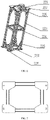
- FIG. 1 is a schematic structural diagram of a vehicle body chassis support provided by an embodiment of a system and a method for assembling a double-deck vehicle body according to the present invention
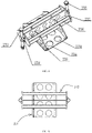
- FIG. 2 is a schematic structural diagram of an upper floor support provided by an embodiment of a system and a method for assembling a double-deck vehicle body according to the present invention
- FIG. 3 is a front view of a structure for an upper floor support provided by an embodiment of a system and a method for assembling a double-deck vehicle body according to the present invention.
- a system for assembling a double-deck vehicle body of according to an embodiment of the present invention includes: a vehicle body chassis support 1 and an upper floor support 2.
- the vehicle body chassis 1 support includes a crossbeam, an end support 11, and an intermediate support 12, where two ends of the crossbeam are respectively arranged with an end support 11, and the middle of the crossbeam is arranged the intermediate support 12; the height of the end support 11 is greater than that of the intermediate support 12; the upper surface of the end support 11 and the upper surface of the intermediate support 12 are configured to be closely fitted to the lower surface of the vehicle body chassis; and the upper floor support 2 is detachably arranged at the vehicle body chassis for supporting the upper floor of the vehicle body.
- the height of the end support 11 is greater than the height of the intermediate support 12 by a difference that equals to a difference between the heights of the two sides and the middle of the lower surface of the vehicle body chassis.
- the difference between the heights of the end support 11 and the intermediate support 12 depends on the specific condition of the vehicle body chassis.
- the length of the crossbeam of the present invention is determined by the length of the vehicle body chassis.
- the quantity and occupied length of the end supports 11 are determined by the length of the two sides of the vehicle body chassis.
- the quantity and occupied length of the intermediate supports 12 are determined by the length of the middle of the vehicle body chassis.
- the vehicle body chassis support of the system for assembling a double-deck vehicle body provided by the present invention includes the crossbeam, the end support, and the intermediate support.
- the end support has a greater height than the intermediate support, which can stabilize the double-deck vehicle body during the assembly process thereof and provides support for other components.
- the upper floor support connects the vehicle body chassis and the upper floor during the assembly process of the double-deck vehicle body, thereby supporting the upper floor to ensure the strength and rigidity of the cross section of the vehicle body.
- the crossbeam includes a first crossbeam 13 and a second crossbeam 14 arranged in parallel, with a plurality of connection crossbeams 15 arranged in parallel between the first crossbeam 13 and the second crossbeam 14.
- the connection crossbeam 15 is arranged the intermediate support 12, two ends of the first crossbeam 13 are arranged the end supports 11, and two ends of the second crossbeam 14 are arranged the end supports 11, respectively.
- the middle part of the double-deck aluminum alloy vehicle body chassis is a U-shaped structure.
- the first beam 13 and the second beam 14 are used to support both sides of the U-shaped vehicle body chassis, and the connection beam 15 is used to support the middle of the U-shaped floor.
- the quantity of connection beams 15 is six, and the distance between two adjacent connection beams 15 is 2.5 meters.
- the connection beams 15 are evenly distributed along the longitudinal direction of the vehicle body. The quantity and spacing of the connection beams 15 are based on the length of the middle part of the bottom of the vehicle body and the embodiment, and are not particularly limited herein.
- an upper part of the end support 11 is arranged a height adjustable screw 16.
- the screw 16 is provided so that the end support 11 may have some adjustability, and a worker can fine-tune the screw 16 to ensure that the end support 11 is in close contact with both sides of the vehicle body chassis.
- the upper floor support 2 includes a chassis connection frame 21, an intermediate support frame 22, and an upper support frame 23, and the width of the chassis connection frame 2 is narrower than that of the vehicle body.
- the upper floor support 2 is used to support the upper floor, assembling workers and equipment on the upper floor during the assembly work.
- the vehicle body chassis connecting frame 21 is located on the vehicle body chassis
- the intermediate support frame 22 is located on the vehicle body chassis connecting frame 21
- the upper support frame 23 is located on the intermediate support frame 22.
- the upper floor support 2 is a combined structure of the vehicle body chassis connecting frame 21, the intermediate support frame 22, and the upper support frame 23, and the three are detachably connected, which is convenient for assembly and use in the compartment of the carriage.
- FIG. 4 is a schematic structural diagram of a chassis connection frame provided by an embodiment of a system and a method for assembling a double-deck vehicle body according to the present invention
- FIG.5 is a front view of the chassis connection frame provided by the embodiment of a system and a method for assembling a double-deck vehicle body according to the present invention.
- the chassis connection frame 21 includes a first upper frame 211 and a first lower frame 212, which are connected through a first column 213. An end of the first upper frame 211 is connected with that of the first lower frame 212 through a first reinforcing plate 214.
- a stiffening plate 215 is arranged between the first upper frame 211 and the first column 213.
- a connection block 216 is arranged at the bottom of the first lower frame 212.
- a first connection plate 217 is arranged at the upper part of the first upper frame, and is provided with a connection hole.
- FIG.6 is a schematic structural diagram of an intermediate support frame provided by an embodiment of a system and a method for assembling a double-deck vehicle body according to the present invention
- FIG.7 is a top view of an intermediate support frame provided by an embodiment of a system and a method for assembling a double-deck vehicle body according to the present invention. As shown in FIG. 6 and
- the quantity of the intermediate support frames 22 is two, which are respectively located at both ends of the upper surface of the chassis connection frame 21.
- Each of the intermediate support frames 22 includes a second upper frame 221 and a second lower frame 222, which are connected by a second column 223.
- a reinforcing rib 224 is arranged between second columns 223.
- a second reinforcing plate 225 is arranged between the second columns 223 and the second upper frame 221, and between the second columns 223 and the second lower frame 222.
- a second connection plate 226 is arranged at a lower part of the second lower frame 222.
- a third connection plate 227 is arranged at an upper part of the second upper frame221. The second connection plate 226 and the third connection plate 227 are arranged with a connection hole.
- connection between the intermediate support frame 22 and the chassis connection frame 21 is implemented by bolts passing through the connection holes of the first connection plate 217 and the second connection plate 226.
- FIG. 8 is a schematic structural diagram of an upper support frame provided by an embodiment of a system and a method for assembling a double-deck vehicle body according to the present invention
- FIG. 9 is a top view of an upper support frame provided by an embodiment of a system and a method for assembling a double-deck vehicle body according to the present invention.
- each of the intermediate support frames 22, is arranged on top with an upper support frame 23, and each of the upper support frames 23 includes a fourth connection plate 231, an intermediate bracket 232, and a screw 233.
- the fourth connection plate 231 includes a bottom plate 234 and a side plate 235.
- the bottom plate 234 is arranged with a connection hole.
- the side plate 235 is arranged with a groove.
- the intermediate bracket 232 includes a support plate 236, and fifth connection plates 237 located on both ends of the support plate 236, and the support plate 236 engages with, and is welded to, the groove of the side plate 235.
- the screw 233 is connected to the fifth connection plate 237 through a bent connection plate 238.
- connection between the upper support frame 23 and the middle support frame 22 is connected by a bolt passing through the connection holes of the third connection plate 227 and the bottom plate 234.
- connection plate 231 and the intermediate bracket 232 are arranged with a weight reduction circular hole 239.
- the upper floor support 2 is realized by one chassis connection frame 21, two intermediate support frames 22, and two upper support frames 23, all of which joined by bolts, which facilitates installation and disassembly during the assembly process of the vehicle body. Moreover, by adapting the height of the second column 223 in the middle support frame 22 to the variations in the height of the upper floor, the fine adjustment of the height direction of the upper floor support 2 can be achieved by adjusting the height of the screw 233 in the upper support frame 23.
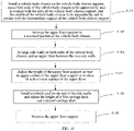
- FIG. 10 is a flowchart of a method for assembling a double-deck vehicle body provided by an embodiment of a system and a method for assembling a double-deck vehicle body according to the present invention. As shown in FIG. 10 , the method for assembling a double-deck vehicle body using the above-mentioned double-deck car body assembly system.
- the method for assembling a double-deck vehicle body includes:
- the quantity of the upper floor supports 2 in step S102 is three, and the three upper floor supports are respectively arranged at both ends and the middle of the lower recess of the vehicle body chassis.
- the vehicle body chassis support can stabilize the vehicle body chassis and provide a good support for the installation of other components.
- the upper floor support connects the vehicle body chassis and the upper floor during the assembly process of the double-deck vehicle body, thereby supporting the upper floor and ensuring the strength and rigidity of the cross section of the vehicle body.
- the upper floor support is easy to be installed and removed, and enables changing the width and height of the upper floor support according to the size of the vehicle body structure, so as to meet the requirements of vehicle bodies of various dimensions.
Landscapes
- Engineering & Computer Science (AREA)
- Chemical & Material Sciences (AREA)
- Combustion & Propulsion (AREA)
- Transportation (AREA)
- Mechanical Engineering (AREA)
- Manufacturing & Machinery (AREA)
- Body Structure For Vehicles (AREA)
Description
- The present invention relates to the field of rail vehicle assembly and, in particular, to a system and a method for assembling a double-deck vehicle body.
- In present rolling stock industry, an aluminum alloy vehicle body, which includes a chassis, a left wall, a right wall, a roof and an end wall (or plus a driver's cab if it is a locomotive), has a single-deck structure. The vehicle body is provided internally with a wooden floor and vehicle interiors. Seats are also provided for carrying passengers or objects. Should the single-deck vehicle body be used to alleviate the burden of the heavy passenger flow both home and abroad, the mileage of the railway will need to be increased, which will involve not only heavy investments, but also more occupied farmland. Instead, if a double-deck vehicle body is used, its large capacity can increase the passenger capacity by more than 45% and reduce the operating cost by 25% as compared with a single-deck train of the same length, and with less investment and without more occupied farmland, which is beneficiary to the transportation service for the rapidly increasing number of commuters in the city.
- However, at present, there is no complete and sophisticated process for assembling a double-deck vehicle body in our country. In the prior art, a single-deck vehicle body chassis can be well supported during single-deck vehicle body assembly because the lower surface and the supported upper part of the single-deck vehicle body chassis are both flat. Instead, a double-deck vehicle body chassis is low in the middle, high on both sides, and the middle part is U-shaped. Therefore, the two sides of the double-deck vehicle body chassis cannot be supported using the same chassis support for assembling the single-deck vehicle body because the middle portion of the flat chassis support will interfere with the U-shaped vehicle body chassis. An example for such a double-deck vehicle body chassis assembly is given in
CN 101 624 073B - Based on the above-mentioned problems, the present invention proposes a system and a method for assembling a double-deck car body.
- The present invention provides a system and a method for assembling a double-deck vehicle body, where the system for assembling a double-deck vehicle body meets a need for supporting the various heights of the lower surface of the double-deck vehicle body chassis, and can ensure the rigidity and strength requirements of the cross-section of the vehicle body during the assembly process.
- An aspect of the present invention provides a system for assembling a double-deck vehicle body, including: a vehicle body chassis support and an upper floor support;
- the vehicle body chassis support includes a crossbeam, end supports, and an intermediate support, where the end supports are arranged separately at two ends of the crossbeam, the intermediate support is arranged at the middle of the crossbeam, a height of the end supports is greater than a height of the intermediate support, an upper surface of the end supports and an upper surface of the intermediate support are configured to be closely fitted to a lower surface of a vehicle body chassis; and
- the upper floor support is detachably arranged on a vehicle body chassis for supporting an upper floor of the vehicle body.
- The system for assembling a double-deck vehicle body as described above, where upper parts of the end supports are arranged with height adjustable screws.
- The system for assembling a double-deck vehicle body as described above, where the crossbeam includes a first crossbeam and a second crossbeam arranged in parallel, and a plurality of connection crossbeams are arranged in parallel between the first crossbeam and the second crossbeam; and
the intermediate support is arranged on the connection crossbeams, the end supports are separately arranged on two ends of the first crossbeam and two ends of the second crossbeam. - The system for assembling a double-deck vehicle body as described above, where the upper floor support includes a chassis connection frame, an intermediate support frame, and an upper support frame, and a width of the chassis connection frame is smaller than a width of a vehicle body.
- The system for assembling a double-deck vehicle body as described above, where the chassis connection frame includes a first upper frame and a first lower frame, which are connected through a first column, an end of the first upper frame is connected with an end of the first lower frame through a first reinforcing plate, a stiffening plate is arranged between the first upper frame and the first column, a connection block is arranged on a bottom of the first lower frame, a first connection plate is arranged on an upper part of the first upper frame, and a connection hole is arranged on the first connection plate;
- a quantity of the intermediate support frames is two, which are separately located at two ends of an upper surface of the chassis connection frame, each intermediate support frame includes a second upper frame and a second lower frame, which are connected through second columns, a reinforcing rib is arranged between the second columns, a second reinforcing plate is arranged between the second column and the second upper frame, and between the second column and the second lower frame, a second connection plate is arranged at a lower part of the second lower frame, a third connection plate is arranged at an upper part of the second upper frame, and the second connection plate and the third connection plate are arranged with a connection hole;
- an upper support frame is arranged on each of the intermediate support frames, and each upper support frame includes a fourth connection plate, an intermediate bracket, and a screw, where the fourth connection plate includes a bottom plate and a side plate, the bottom plate is arranged with a connection hole, the side plate is arranged with a groove, the intermediate bracket includes a support plate, and fifth connection plates located on both sides of the support plate, and the support plate engages with the groove of the side plate, and the screw is connected to the fifth connection plate through a bent connection plate.
- The system for assembling a double-deck vehicle body as described above, where the fourth connection plate and the intermediate bracket are arranged with a weight reduction circular hole.
- Another aspect of the present invention provides a method for assembling a double-deck vehicle body, where the method involves using the system for assembling a double-deck vehicle body as described above, and the method for assembling a double-deck vehicle body includes:
- installing a vehicle body chassis on the vehicle body chassis support, so that both ends of the vehicle body chassis are supported by and in contact with ends of the vehicle body chassis support, and a middle of the vehicle body chassis is supported by and in contact with an intermediate support of the vehicle body chassis support;
- arranging the upper floor support in a recessed portion of the vehicle body chassis;
- arranging side walls on both sides of the vehicle body chassis, and an upper floor between two side walls;
- adjusting a height of the upper floor support, so that an upper surface of the upper floor support is closely fitted to a lower surface of the upper floor;
- installing a roof on top of the side walls, and adjusting heights of a first carriage deck and a second carriage deck; and
- removing the upper floor support.
- The method for assembling a double-deck vehicle body as described above, where the quantity of the upper floor support is three, and the arranging the upper floor support in a recessed portion of the vehicle body chassis includes:
arranging the three upper floor supports at both ends and a middle, respectively, of the recessed portion of the vehicle body chassis. - The vehicle body chassis support of the system for assembling the double-deck vehicle body provided by the present invention includes the crossbeam, the end supports, and the intermediate support, where the end supports are taller than the intermediate support, thus offering stability to a vehicle body chassis during the assembly process of the double-deck body and providing support for other components. The upper floor support connects the vehicle body chassis and an upper floor during the assembly process of the double-deck vehicle body, providing support for the upper floor to ensure the strength and rigidity of the cross section of the vehicle body. Moreover, the upper floor support is easy to install and remove, and the width and height of the upper floor support is adjustable to the dimensions of the vehicle body structure, so as to be adaptable to the requirements of vehicle bodies of various dimensions.
- In order to explain clearly technical solutions of the embodiments of the present invention or the prior art, the drawings that will need to be used in the description of the embodiments or the prior art will be briefly introduced below. Obviously, the drawings in the following description are merely some embodiments of the present invention. For those skilled in the art, other drawings can be derived based on these drawings without paying any creative work.
-
FIG. 1 is a schematic structural diagram of a vehicle body chassis support provided by an embodiment of a system and a method for assembling a double-deck vehicle body according to the present invention. -
FIG. 2 is a schematic structural diagram of an upper floor support provided by an embodiment of a system and a method for assembling a double-deck vehicle body according to the present invention. -
FIG. 3 is a front view of a structure for an upper floor support provided by an embodiment of a system and a method for assembling a double-deck vehicle body according to the present invention. -
FIG. 4 is a schematic structural diagram of a chassis connection frame provided by an embodiment of a system and a method for assembling a double-deck vehicle body according to the present invention. -
FIG. 5 is a front view of the chassis connection frame provided by an embodiment of a system and a method for assembling a double-deck vehicle body according to the present invention. -
FIG. 6 is a schematic structural diagram of an intermediate support frame provided by an embodiment of a system and a method for assembling a double-deck vehicle body according to the present invention. -
FIG. 7 is a top view of an intermediate support frame provided by an embodiment of a system and a method for assembling a double-deck vehicle body according to the present invention. -
FIG. 8 is a schematic structural diagram of an upper support frame provided by an embodiment of a system and a method for assembling a double-deck vehicle body according to the present invention. -
FIG. 9 is a top view of an upper support frame provided by an embodiment of a system and a method for assembling a double-deck vehicle body according to the present invention. -
FIG. 10 is a flowchart of a method for assembling a double-deck vehicle body provided by an embodiment of a system and a method for assembling a double-deck vehicle body according to the present invention. - In order to make the objectives, technical solutions, and advantages of the embodiments of the present invention clearer, the technical solutions in the embodiments of the present invention will be clearly and completely described with reference to the accompanying drawings in the embodiments of the present invention. Obviously, the described embodiments are a part but not all of the embodiments of the present invention. Based on the embodiments of the present invention, all other embodiments obtained by the skilled in the art without any creative work shall be within the scope of the present invention.
- In the description of the present invention, it should be understood that the orientations or positional relationships indicated by the terms "up" and "down" are based on what are shown in the drawings, and are only for the convenience of describing the present invention and simplifying the description, rather than indicating or implying that the device or element have to have such a particular orientation, or have to be constructed and operated in such a particular orientation, and therefore should not be understood as a limitation to the invention. In addition, the terms "first," "second," "third," "fourth," and "fifth" are only used for descriptive purposes, and not to be interpreted as indicating or implying relative importance or implicitly indicating the number of technical features. Moreover, "a plurality" means two or more in the description of the present invention, unless otherwise stated.
- A double-deck aluminum alloy vehicle body chassis is a structure depressed in the middle, raised on both sides, with a U-shaped middle part. Therefore, the two sides of the double-deck vehicle body chassis cannot be supported by the existing single-deck vehicle body chassis support, and the middle part of the horizontal chassis support will interfere with the U-shaped vehicle body chassis. Moreover, during the assembly process of the upper floor, the upper floor is prone to collapse and deformation, and cannot support the load of workers and materials when welding roofs and side walls. Accordingly, the present invention proposes a system and a method for assembling a double-deck car body.
-
FIG. 1 is a schematic structural diagram of a vehicle body chassis support provided by an embodiment of a system and a method for assembling a double-deck vehicle body according to the present invention,FIG. 2 is a schematic structural diagram of an upper floor support provided by an embodiment of a system and a method for assembling a double-deck vehicle body according to the present invention, andFIG. 3 is a front view of a structure for an upper floor support provided by an embodiment of a system and a method for assembling a double-deck vehicle body according to the present invention. As shown inFIG. 1 and FIG. 2 , a system for assembling a double-deck vehicle body of according to an embodiment of the present invention includes: a vehiclebody chassis support 1 and anupper floor support 2. - The
vehicle body chassis 1 support includes a crossbeam, anend support 11, and anintermediate support 12, where two ends of the crossbeam are respectively arranged with anend support 11, and the middle of the crossbeam is arranged theintermediate support 12; the height of theend support 11 is greater than that of theintermediate support 12; the upper surface of theend support 11 and the upper surface of theintermediate support 12 are configured to be closely fitted to the lower surface of the vehicle body chassis; and theupper floor support 2 is detachably arranged at the vehicle body chassis for supporting the upper floor of the vehicle body. - In the present invention, the height of the
end support 11 is greater than the height of theintermediate support 12 by a difference that equals to a difference between the heights of the two sides and the middle of the lower surface of the vehicle body chassis. The difference between the heights of theend support 11 and theintermediate support 12 depends on the specific condition of the vehicle body chassis. - The length of the crossbeam of the present invention is determined by the length of the vehicle body chassis. The quantity and occupied length of the end supports 11 are determined by the length of the two sides of the vehicle body chassis. The quantity and occupied length of the
intermediate supports 12 are determined by the length of the middle of the vehicle body chassis. - The vehicle body chassis support of the system for assembling a double-deck vehicle body provided by the present invention includes the crossbeam, the end support, and the intermediate support. The end support has a greater height than the intermediate support, which can stabilize the double-deck vehicle body during the assembly process thereof and provides support for other components. The upper floor support connects the vehicle body chassis and the upper floor during the assembly process of the double-deck vehicle body, thereby supporting the upper floor to ensure the strength and rigidity of the cross section of the vehicle body.
- Now, the system for assembling a double-deck vehicle body of the present invention will be described in detail in conjuncture with specific embodiments.
- The crossbeam includes a
first crossbeam 13 and asecond crossbeam 14 arranged in parallel, with a plurality ofconnection crossbeams 15 arranged in parallel between thefirst crossbeam 13 and thesecond crossbeam 14. Theconnection crossbeam 15 is arranged theintermediate support 12, two ends of thefirst crossbeam 13 are arranged the end supports 11, and two ends of thesecond crossbeam 14 are arranged the end supports 11, respectively. - The middle part of the double-deck aluminum alloy vehicle body chassis is a U-shaped structure. The
first beam 13 and thesecond beam 14 are used to support both sides of the U-shaped vehicle body chassis, and theconnection beam 15 is used to support the middle of the U-shaped floor. In this embodiment, the quantity of connection beams 15 is six, and the distance between two adjacent connection beams 15 is 2.5 meters. The connection beams 15 are evenly distributed along the longitudinal direction of the vehicle body. The quantity and spacing of the connection beams 15 are based on the length of the middle part of the bottom of the vehicle body and the embodiment, and are not particularly limited herein. - Furthermore, an upper part of the
end support 11 is arranged a heightadjustable screw 16. Thescrew 16 is provided so that theend support 11 may have some adjustability, and a worker can fine-tune thescrew 16 to ensure that theend support 11 is in close contact with both sides of the vehicle body chassis. - The
upper floor support 2 includes achassis connection frame 21, anintermediate support frame 22, and an upper support frame 23, and the width of thechassis connection frame 2 is narrower than that of the vehicle body. Theupper floor support 2 is used to support the upper floor, assembling workers and equipment on the upper floor during the assembly work. The vehicle bodychassis connecting frame 21 is located on the vehicle body chassis, theintermediate support frame 22 is located on the vehicle bodychassis connecting frame 21, and the upper support frame 23 is located on theintermediate support frame 22. Theupper floor support 2 is a combined structure of the vehicle bodychassis connecting frame 21, theintermediate support frame 22, and the upper support frame 23, and the three are detachably connected, which is convenient for assembly and use in the compartment of the carriage. -
FIG. 4 is a schematic structural diagram of a chassis connection frame provided by an embodiment of a system and a method for assembling a double-deck vehicle body according to the present invention, andFIG.5 is a front view of the chassis connection frame provided by the embodiment of a system and a method for assembling a double-deck vehicle body according to the present invention. As shown inFIG. 4 and FIG. 5 , thechassis connection frame 21 includes a firstupper frame 211 and a firstlower frame 212, which are connected through afirst column 213. An end of the firstupper frame 211 is connected with that of the firstlower frame 212 through a first reinforcingplate 214. Astiffening plate 215 is arranged between the firstupper frame 211 and thefirst column 213. Aconnection block 216 is arranged at the bottom of the firstlower frame 212. Afirst connection plate 217 is arranged at the upper part of the first upper frame, and is provided with a connection hole. -
FIG.6 is a schematic structural diagram of an intermediate support frame provided by an embodiment of a system and a method for assembling a double-deck vehicle body according to the present invention, andFIG.7 is a top view of an intermediate support frame provided by an embodiment of a system and a method for assembling a double-deck vehicle body according to the present invention. As shown inFIG. 6 and -
FIG. 7 , the quantity of the intermediate support frames 22 is two, which are respectively located at both ends of the upper surface of thechassis connection frame 21. Each of the intermediate support frames 22 includes a secondupper frame 221 and a secondlower frame 222, which are connected by asecond column 223. A reinforcingrib 224 is arranged betweensecond columns 223. A second reinforcingplate 225 is arranged between thesecond columns 223 and the secondupper frame 221, and between thesecond columns 223 and the secondlower frame 222. Asecond connection plate 226 is arranged at a lower part of the secondlower frame 222. Athird connection plate 227 is arranged at an upper part of the second upper frame221. Thesecond connection plate 226 and thethird connection plate 227 are arranged with a connection hole. - The connection between the
intermediate support frame 22 and thechassis connection frame 21 is implemented by bolts passing through the connection holes of thefirst connection plate 217 and thesecond connection plate 226. -
FIG. 8 is a schematic structural diagram of an upper support frame provided by an embodiment of a system and a method for assembling a double-deck vehicle body according to the present invention, andFIG. 9 is a top view of an upper support frame provided by an embodiment of a system and a method for assembling a double-deck vehicle body according to the present invention. As shown inFIG. 8 and FIG. 9 , each of the intermediate support frames 22, is arranged on top with an upper support frame 23, and each of the upper support frames 23 includes afourth connection plate 231, anintermediate bracket 232, and ascrew 233. Thefourth connection plate 231 includes abottom plate 234 and aside plate 235. Thebottom plate 234 is arranged with a connection hole. Theside plate 235 is arranged with a groove. Theintermediate bracket 232 includes asupport plate 236, andfifth connection plates 237 located on both ends of thesupport plate 236, and thesupport plate 236 engages with, and is welded to, the groove of theside plate 235. Thescrew 233 is connected to thefifth connection plate 237 through abent connection plate 238. - The connection between the upper support frame 23 and the
middle support frame 22 is connected by a bolt passing through the connection holes of thethird connection plate 227 and thebottom plate 234. - Further, the
fourth connection plate 231 and theintermediate bracket 232 are arranged with a weight reductioncircular hole 239. - In the embodiment of the present invention, the
upper floor support 2 is realized by onechassis connection frame 21, two intermediate support frames 22, and two upper support frames 23, all of which joined by bolts, which facilitates installation and disassembly during the assembly process of the vehicle body. Moreover, by adapting the height of thesecond column 223 in themiddle support frame 22 to the variations in the height of the upper floor, the fine adjustment of the height direction of theupper floor support 2 can be achieved by adjusting the height of thescrew 233 in the upper support frame 23. - A method for assembling a double-deck vehicle body is provided by another aspect of the present invention.
FIG. 10 is a flowchart of a method for assembling a double-deck vehicle body provided by an embodiment of a system and a method for assembling a double-deck vehicle body according to the present invention. As shown inFIG. 10 , the method for assembling a double-deck vehicle body using the above-mentioned double-deck car body assembly system. The method for assembling a double-deck vehicle body includes: - S101: Install a vehicle body chassis on the vehicle body chassis support, cause both ends of the vehicle body chassis to be supported by and in contact with the ends of the vehicle body chassis support, and the middle of the vehicle body chassis to be supported by and in contact with the intermediate support of the vehicle body chassis support.
- S102: Arrange the upper floor support in a recessed portion of the vehicle body chassis.
- S103: Arrange side walls on both sides of the vehicle body chassis, and an upper floor between the two side walls.
- S104: Adjust the height of the upper floor support, so that an upper surface of the upper floor support is in close fit with a lower surface of the upper floor.
- S105: Install a vehicle roof on the top of the side walls, and adjust the height of a first carriage deck and a second carriage deck.
- S106: Remove the upper floor support.
- Further, in order to ensure that the upper floor is uniformly loaded during the installation process, the quantity of the upper floor supports 2 in step S102 is three, and the three upper floor supports are respectively arranged at both ends and the middle of the lower recess of the vehicle body chassis.
- According to the method for assembling a double-deck vehicle body of the present invention, during the assembly process of the double-deck vehicle body chassis, the vehicle body chassis support can stabilize the vehicle body chassis and provide a good support for the installation of other components. The upper floor support connects the vehicle body chassis and the upper floor during the assembly process of the double-deck vehicle body, thereby supporting the upper floor and ensuring the strength and rigidity of the cross section of the vehicle body. Moreover, the upper floor support is easy to be installed and removed, and enables changing the width and height of the upper floor support according to the size of the vehicle body structure, so as to meet the requirements of vehicle bodies of various dimensions.
- Finally, it should be noted that the above embodiments are only used to illustrate, rather than to limit, the technical solution of the present invention. Although the present invention has been described in detail with reference to the foregoing embodiments, those skilled in the art should understand that: the technical solutions described in the foregoing embodiments can still be modified within the scope of the claims.
Claims (9)
- A system for assembling a double-deck vehicle body, comprising: a vehicle body chassis support (1) and an upper floor support (2), wherein:the vehicle body chassis support (1) comprises a crossbeam (13, 14), end supports (11), and an intermediate support (12), wherein the end supports (11) are arranged separately at two ends of the crossbeam (13, 14), the intermediate support (12) is arranged at the middle of the crossbeam (13, 14), a height of the end supports (11) is greater than a height of the intermediate support (12), upper surfaces of the end supports (11) and an upper surface of the intermediate support (12) are configured to be closely fitted to a lower surface of a vehicle body chassis; andthe upper floor support (2) is detachably arranged on the vehicle body chassis for supporting an upper floor of the vehicle body.
- The system for assembling a double-deck vehicle body according to claim 1, wherein upper parts of the end supports (11) are arranged with height adjustable screws (16).
- The system for assembling a double-deck vehicle body according to claim 1, wherein the crossbeam (13, 14) comprises a first crossbeam (13) and a second crossbeam (14) arranged in parallel, and a plurality of connection crossbeams (15) are arranged in parallel between the first crossbeam (13) and the second crossbeam (14); and
the intermediate support (12) is arranged on the connection crossbeams (15), the end supports (11) are separately arranged on two ends of the first crossbeam (13) and two ends of the second crossbeam (14). - The system for assembling a double-deck vehicle body according to claim 1, wherein the upper floor support (2) comprises a chassis connection frame (21), an intermediate support frame (22), and an upper support frame (23), and a width of the chassis connection frame (21) is smaller than a width of a vehicle body.
- The system for assembling a double-deck vehicle body according to claim 4, wherein:the chassis connection frame (21) comprises a first upper frame (211) and a first lower frame (212), which are connected through a first column (213), an end of the first upper frame (211) is connected with an end of the first lower frame (212) through a first reinforcing plate (214), a stiffening plate (215) is arranged between the first upper frame (211) and the first column (213), a connection block (216) is arranged on a bottom of the first lower frame (212), a first connection plate (217) is arranged on an upper part of the first upper frame (211), and a connection hole is arranged on the first connection plate (217);a quantity of the intermediate support frame (22) is two, which are separately located at two ends of an upper surface of the chassis connection frame (21), each intermediate support frame (22) comprises a second upper frame (221) and a second lower frame (222), which are connected through second columns (223), a reinforcing rib (224) is arranged between the second columns (223), a second reinforcing plate (225) is arranged between the second column (223) and the second upper frame (221), and between the second column (223) and the second lower frame (222), a second connection plate (226) is arranged at a lower part of the second lower frame (222), a third connection plate (227) is arranged at an upper part of the second upper frame (221), and the second connection plate (226) and the third connection plate (227) are arranged with a connection hole;an upper support frame (23) is arranged on each intermediate support frame (22), and each upper support frame (23) comprises a fourth connection plate (231), an intermediate bracket (232), and a screw (233), wherein the fourth connection plate (231) comprises a bottom plate (234) and a side plate (235), the bottom plate (234) is arranged with a connection hole, the side plate (235) is arranged with a groove, the intermediate bracket (232) comprises a support plate (236), and fifth connection plates (237) located on both sides of the support plate (236), and the support plate (236) engages with the groove of the side plate (235), and the screw (233) is connected to the fifth connection plate (237) through a bent connection plate (238).
- The system for assembling a double-deck vehicle body according to claim 5, wherein the fourth connection plate (231) and the intermediate bracket (232) are arranged with a weight reduction circular hole (239).
- The system for assembling a double-deck vehicle body according to claim 1, wherein the upper floor support (2) is adapted to engage with a recessed portion of the vehicle body chassis, wherein the quantity of the upper floor support (2) is three, wherein the three upper floor supports (2) are adapted to engage with both ends and a middle portion, respectively, of a recessed portion of the vehicle body chassis.
- A method for assembling a double-deck vehicle body, wherein the method involves using a system for assembling a double-deck vehicle body according to any one of claims 1-7, and the method comprises:installing (S101) a vehicle body chassis on the vehicle body chassis support (1), so that both ends of the vehicle body chassis are supported by and in contact with ends of the vehicle body chassis support (1), and a middle of the vehicle body chassis is supported by and in contact with an intermediate support (12) of the vehicle body chassis support (1);arranging (S102) the upper floor support (2) in a recessed portion of the vehicle body chassis;arranging (S103) side walls on both sides of the vehicle body chassis, and an upper floor between two side walls;adjusting (S104) a height of the upper floor support (2), so that an upper surface of the upper floor support (2) is closely fitted to a lower surface of the upper floor;installing (S105) a roof on top of the side walls, and adjusting heights of a first carriage deck and a second carriage deck; andremoving (S106) the upper floor support (2).
- The method for assembling a double-deck vehicle body according to claim 8, wherein the quantity of the upper floor support (2) is three, and the arranging (S102) the upper floor support (2) in a recessed portion of the vehicle body chassis comprises:
arranging the three upper floor supports (2) at both ends and a middle, respectively, of the recessed portion of the vehicle body chassis.
Applications Claiming Priority (2)
| Application Number | Priority Date | Filing Date | Title |
|---|---|---|---|
| CN201710693833.4A CN107458501B (en) | 2017-08-14 | 2017-08-14 | Double-deck bus body assembly system and method |
| PCT/CN2017/117620 WO2019033670A1 (en) | 2017-08-14 | 2017-12-21 | System and method for assembling double-decker vehicle body |
Publications (3)
| Publication Number | Publication Date |
|---|---|
| EP3659903A1 EP3659903A1 (en) | 2020-06-03 |
| EP3659903A4 EP3659903A4 (en) | 2020-12-02 |
| EP3659903B1 true EP3659903B1 (en) | 2022-04-20 |
Family
ID=60549629
Family Applications (1)
| Application Number | Title | Priority Date | Filing Date |
|---|---|---|---|
| EP17921832.6A Active EP3659903B1 (en) | 2017-08-14 | 2017-12-21 | System and method for assembling double-decker vehicle body |
Country Status (5)
| Country | Link |
|---|---|
| US (1) | US11352080B2 (en) |
| EP (1) | EP3659903B1 (en) |
| CN (1) | CN107458501B (en) |
| PT (1) | PT3659903T (en) |
| WO (1) | WO2019033670A1 (en) |
Families Citing this family (4)
| Publication number | Priority date | Publication date | Assignee | Title |
|---|---|---|---|---|
| CN107458501B (en) * | 2017-08-14 | 2019-04-23 | 中车唐山机车车辆有限公司 | Double-deck bus body assembly system and method |
| CN111775989B (en) * | 2019-04-03 | 2021-07-27 | 中车唐山机车车辆有限公司 | Double-deck rail vehicle and automobile body thereof |
| CN112092851B (en) * | 2020-09-01 | 2021-11-02 | 中车长春轨道客车股份有限公司 | Underframe synthesis positioning device and positioning method thereof |
| CN112355992A (en) * | 2020-10-22 | 2021-02-12 | 中车青岛四方机车车辆股份有限公司 | Rail transit train cab storage and support tool and method |
Family Cites Families (16)
| Publication number | Priority date | Publication date | Assignee | Title |
|---|---|---|---|---|
| BE678577A (en) * | 1965-04-27 | 1966-09-01 | ||
| US4033033A (en) * | 1976-02-23 | 1977-07-05 | Rohr Industries, Inc. | Bus manufacturing mechanism and method |
| JPS6112474A (en) * | 1984-06-26 | 1986-01-20 | Toyota Motor Corp | Vehicle body assembling device |
| JP2831999B2 (en) * | 1987-12-01 | 1998-12-02 | マツダ株式会社 | Undercarriage assembly device for automobile assembly line |
| WO2009132363A1 (en) * | 2008-04-22 | 2009-10-29 | Singh, Rene | Jig for the manufacture of bus frames |
| JP5263535B2 (en) * | 2009-06-25 | 2013-08-14 | 近畿車輌株式会社 | Low floor vehicle connector installation structure |
| CN101624073B (en) * | 2009-08-18 | 2011-02-09 | 安徽安凯汽车股份有限公司 | Assembling method of double-layer bus framework bus body |
| US8839507B2 (en) * | 2009-12-15 | 2014-09-23 | Comau, Inc. | Remote locking apparatus for securing a vehicle body to a vehicle body support |
| DE102010000777A1 (en) * | 2010-01-11 | 2011-07-14 | Ford Global Technologies, LLC, Mich. | Method for mounting a body component to a body shell and holder |
| WO2011137283A2 (en) * | 2010-04-30 | 2011-11-03 | Comau, Inc | Variable vehicle body fixed framer and method |
| CN202162519U (en) * | 2011-05-17 | 2012-03-14 | 南方汇通股份有限公司 | Modularized assembling clamp for rail wagon base frame |
| CN202846091U (en) * | 2012-10-29 | 2013-04-03 | 湘潭电机股份有限公司 | Concave type underbed welding combination clamp of lowland plate trailer |
| DE102013112152B4 (en) * | 2013-11-05 | 2024-09-19 | Deutsches Zentrum für Luft- und Raumfahrt e.V. | Vehicle and body for a vehicle |
| CN104097009B (en) * | 2014-07-15 | 2016-01-13 | 南车南京浦镇车辆有限公司 | General-purpose type chassis upright tire |
| CN205465154U (en) * | 2016-02-23 | 2016-08-17 | 中车青岛四方机车车辆股份有限公司 | Rail vehicle stainless steel automobile body assembly device |
| CN107458501B (en) * | 2017-08-14 | 2019-04-23 | 中车唐山机车车辆有限公司 | Double-deck bus body assembly system and method |
-
2017
- 2017-08-14 CN CN201710693833.4A patent/CN107458501B/en active Active
- 2017-12-21 EP EP17921832.6A patent/EP3659903B1/en active Active
- 2017-12-21 WO PCT/CN2017/117620 patent/WO2019033670A1/en not_active Ceased
- 2017-12-21 PT PT179218326T patent/PT3659903T/en unknown
-
2020
- 2020-02-14 US US16/791,847 patent/US11352080B2/en active Active
Also Published As
| Publication number | Publication date |
|---|---|
| EP3659903A4 (en) | 2020-12-02 |
| PT3659903T (en) | 2022-05-09 |
| EP3659903A1 (en) | 2020-06-03 |
| CN107458501A (en) | 2017-12-12 |
| US11352080B2 (en) | 2022-06-07 |
| US20200180715A1 (en) | 2020-06-11 |
| WO2019033670A1 (en) | 2019-02-21 |
| CN107458501B (en) | 2019-04-23 |
Similar Documents
| Publication | Publication Date | Title |
|---|---|---|
| US11352080B2 (en) | System and method for assembling double-deck vehicle body | |
| CN103118920B (en) | For compartment and the manufacture method thereof of rail vehicle | |
| CN101643087B (en) | Automobile body with floor reinforcement | |
| US4275663A (en) | Corrugated vehicle underframe | |
| CN104097647A (en) | Multifunctional coil steel transportation vehicle special for railways | |
| CA2907212C (en) | Variable capacity autorack railcar | |
| CN101559775A (en) | Car body structure | |
| RU2438910C2 (en) | Automotive body integral cargo section | |
| CN103465921A (en) | Special vehicle body for rapid container transportation | |
| CN104245468A (en) | Structurally stable arrangement and method for forming a structurally stable arrangement | |
| CN104228858A (en) | Transport vehicle and vehicle body thereof | |
| RU176585U1 (en) | Tank car | |
| RU2288121C1 (en) | Railway platform for carrying large-size containers | |
| US6641206B1 (en) | Load carrying arrangement for a vehicle | |
| CN109440549B (en) | Suspension type monorail transportation system and track beam thereof | |
| CN114228842B (en) | New forms of energy commodity circulation car, carriage and chassis assembly | |
| CN105835899B (en) | A kind of drawing pull bar mounting interface device and bogie | |
| CN203958145U (en) | A kind of railway special-purpose multifunctional coil steel transportation car | |
| CN210912156U (en) | Connecting structure of lightweight compartment bottom protective steel plate | |
| CN110789549B (en) | End wall structure and tramcar with same | |
| CN109263670B (en) | Low-floor rail vehicle roof and low-floor rail vehicle | |
| CN221068070U (en) | Side beam of chassis of car body | |
| CN107738692B (en) | Profile boundary beam of aluminum alloy side curtain semitrailer and frame thereof | |
| CN206493954U (en) | A kind of drawing pull bar mounting interface device and bogie | |
| US2815723A (en) | Reinforced bottom structure for railway cars and similar vehicles |
Legal Events
| Date | Code | Title | Description |
|---|---|---|---|
| STAA | Information on the status of an ep patent application or granted ep patent |
Free format text: STATUS: THE INTERNATIONAL PUBLICATION HAS BEEN MADE |
|
| PUAI | Public reference made under article 153(3) epc to a published international application that has entered the european phase |
Free format text: ORIGINAL CODE: 0009012 |
|
| STAA | Information on the status of an ep patent application or granted ep patent |
Free format text: STATUS: REQUEST FOR EXAMINATION WAS MADE |
|
| 17P | Request for examination filed |
Effective date: 20200225 |
|
| AK | Designated contracting states |
Kind code of ref document: A1 Designated state(s): AL AT BE BG CH CY CZ DE DK EE ES FI FR GB GR HR HU IE IS IT LI LT LU LV MC MK MT NL NO PL PT RO RS SE SI SK SM TR |
|
| AX | Request for extension of the european patent |
Extension state: BA ME |
|
| DAV | Request for validation of the european patent (deleted) | ||
| DAX | Request for extension of the european patent (deleted) | ||
| A4 | Supplementary search report drawn up and despatched |
Effective date: 20201030 |
|
| RIC1 | Information provided on ipc code assigned before grant |
Ipc: B62D 65/02 20060101AFI20201026BHEP Ipc: B62D 31/04 20060101ALI20201026BHEP Ipc: B62D 31/02 20060101ALI20201026BHEP |
|
| RIC1 | Information provided on ipc code assigned before grant |
Ipc: B62D 65/02 20060101AFI20210712BHEP Ipc: B62D 31/02 20060101ALI20210712BHEP Ipc: B62D 31/04 20060101ALI20210712BHEP |
|
| GRAP | Despatch of communication of intention to grant a patent |
Free format text: ORIGINAL CODE: EPIDOSNIGR1 |
|
| STAA | Information on the status of an ep patent application or granted ep patent |
Free format text: STATUS: GRANT OF PATENT IS INTENDED |
|
| INTG | Intention to grant announced |
Effective date: 20210906 |
|
| GRAJ | Information related to disapproval of communication of intention to grant by the applicant or resumption of examination proceedings by the epo deleted |
Free format text: ORIGINAL CODE: EPIDOSDIGR1 |
|
| STAA | Information on the status of an ep patent application or granted ep patent |
Free format text: STATUS: REQUEST FOR EXAMINATION WAS MADE |
|
| INTC | Intention to grant announced (deleted) | ||
| GRAP | Despatch of communication of intention to grant a patent |
Free format text: ORIGINAL CODE: EPIDOSNIGR1 |
|
| STAA | Information on the status of an ep patent application or granted ep patent |
Free format text: STATUS: GRANT OF PATENT IS INTENDED |
|
| INTG | Intention to grant announced |
Effective date: 20220128 |
|
| GRAS | Grant fee paid |
Free format text: ORIGINAL CODE: EPIDOSNIGR3 |
|
| GRAA | (expected) grant |
Free format text: ORIGINAL CODE: 0009210 |
|
| STAA | Information on the status of an ep patent application or granted ep patent |
Free format text: STATUS: THE PATENT HAS BEEN GRANTED |
|
| AK | Designated contracting states |
Kind code of ref document: B1 Designated state(s): AL AT BE BG CH CY CZ DE DK EE ES FI FR GB GR HR HU IE IS IT LI LT LU LV MC MK MT NL NO PL PT RO RS SE SI SK SM TR |
|
| REG | Reference to a national code |
Ref country code: GB Ref legal event code: FG4D |
|
| REG | Reference to a national code |
Ref country code: CH Ref legal event code: EP |
|
| REG | Reference to a national code |
Ref country code: PT Ref legal event code: SC4A Ref document number: 3659903 Country of ref document: PT Date of ref document: 20220509 Kind code of ref document: T Free format text: AVAILABILITY OF NATIONAL TRANSLATION Effective date: 20220502 |
|
| REG | Reference to a national code |
Ref country code: IE Ref legal event code: FG4D |
|
| REG | Reference to a national code |
Ref country code: DE Ref legal event code: R096 Ref document number: 602017056406 Country of ref document: DE |
|
| REG | Reference to a national code |
Ref country code: AT Ref legal event code: REF Ref document number: 1484974 Country of ref document: AT Kind code of ref document: T Effective date: 20220515 |
|
| REG | Reference to a national code |
Ref country code: LT Ref legal event code: MG9D |
|
| REG | Reference to a national code |
Ref country code: NL Ref legal event code: MP Effective date: 20220420 |
|
| REG | Reference to a national code |
Ref country code: AT Ref legal event code: MK05 Ref document number: 1484974 Country of ref document: AT Kind code of ref document: T Effective date: 20220420 |
|
| PG25 | Lapsed in a contracting state [announced via postgrant information from national office to epo] |
Ref country code: NL Free format text: LAPSE BECAUSE OF FAILURE TO SUBMIT A TRANSLATION OF THE DESCRIPTION OR TO PAY THE FEE WITHIN THE PRESCRIBED TIME-LIMIT Effective date: 20220420 |
|
| PG25 | Lapsed in a contracting state [announced via postgrant information from national office to epo] |
Ref country code: SE Free format text: LAPSE BECAUSE OF FAILURE TO SUBMIT A TRANSLATION OF THE DESCRIPTION OR TO PAY THE FEE WITHIN THE PRESCRIBED TIME-LIMIT Effective date: 20220420 Ref country code: NO Free format text: LAPSE BECAUSE OF FAILURE TO SUBMIT A TRANSLATION OF THE DESCRIPTION OR TO PAY THE FEE WITHIN THE PRESCRIBED TIME-LIMIT Effective date: 20220720 Ref country code: LT Free format text: LAPSE BECAUSE OF FAILURE TO SUBMIT A TRANSLATION OF THE DESCRIPTION OR TO PAY THE FEE WITHIN THE PRESCRIBED TIME-LIMIT Effective date: 20220420 Ref country code: HR Free format text: LAPSE BECAUSE OF FAILURE TO SUBMIT A TRANSLATION OF THE DESCRIPTION OR TO PAY THE FEE WITHIN THE PRESCRIBED TIME-LIMIT Effective date: 20220420 Ref country code: GR Free format text: LAPSE BECAUSE OF FAILURE TO SUBMIT A TRANSLATION OF THE DESCRIPTION OR TO PAY THE FEE WITHIN THE PRESCRIBED TIME-LIMIT Effective date: 20220721 Ref country code: FI Free format text: LAPSE BECAUSE OF FAILURE TO SUBMIT A TRANSLATION OF THE DESCRIPTION OR TO PAY THE FEE WITHIN THE PRESCRIBED TIME-LIMIT Effective date: 20220420 Ref country code: ES Free format text: LAPSE BECAUSE OF FAILURE TO SUBMIT A TRANSLATION OF THE DESCRIPTION OR TO PAY THE FEE WITHIN THE PRESCRIBED TIME-LIMIT Effective date: 20220420 Ref country code: BG Free format text: LAPSE BECAUSE OF FAILURE TO SUBMIT A TRANSLATION OF THE DESCRIPTION OR TO PAY THE FEE WITHIN THE PRESCRIBED TIME-LIMIT Effective date: 20220720 Ref country code: AT Free format text: LAPSE BECAUSE OF FAILURE TO SUBMIT A TRANSLATION OF THE DESCRIPTION OR TO PAY THE FEE WITHIN THE PRESCRIBED TIME-LIMIT Effective date: 20220420 |
|
| PG25 | Lapsed in a contracting state [announced via postgrant information from national office to epo] |
Ref country code: RS Free format text: LAPSE BECAUSE OF FAILURE TO SUBMIT A TRANSLATION OF THE DESCRIPTION OR TO PAY THE FEE WITHIN THE PRESCRIBED TIME-LIMIT Effective date: 20220420 Ref country code: PL Free format text: LAPSE BECAUSE OF FAILURE TO SUBMIT A TRANSLATION OF THE DESCRIPTION OR TO PAY THE FEE WITHIN THE PRESCRIBED TIME-LIMIT Effective date: 20220420 Ref country code: LV Free format text: LAPSE BECAUSE OF FAILURE TO SUBMIT A TRANSLATION OF THE DESCRIPTION OR TO PAY THE FEE WITHIN THE PRESCRIBED TIME-LIMIT Effective date: 20220420 Ref country code: IS Free format text: LAPSE BECAUSE OF FAILURE TO SUBMIT A TRANSLATION OF THE DESCRIPTION OR TO PAY THE FEE WITHIN THE PRESCRIBED TIME-LIMIT Effective date: 20220820 |
|
| REG | Reference to a national code |
Ref country code: DE Ref legal event code: R097 Ref document number: 602017056406 Country of ref document: DE |
|
| PG25 | Lapsed in a contracting state [announced via postgrant information from national office to epo] |
Ref country code: SM Free format text: LAPSE BECAUSE OF FAILURE TO SUBMIT A TRANSLATION OF THE DESCRIPTION OR TO PAY THE FEE WITHIN THE PRESCRIBED TIME-LIMIT Effective date: 20220420 Ref country code: SK Free format text: LAPSE BECAUSE OF FAILURE TO SUBMIT A TRANSLATION OF THE DESCRIPTION OR TO PAY THE FEE WITHIN THE PRESCRIBED TIME-LIMIT Effective date: 20220420 Ref country code: RO Free format text: LAPSE BECAUSE OF FAILURE TO SUBMIT A TRANSLATION OF THE DESCRIPTION OR TO PAY THE FEE WITHIN THE PRESCRIBED TIME-LIMIT Effective date: 20220420 Ref country code: EE Free format text: LAPSE BECAUSE OF FAILURE TO SUBMIT A TRANSLATION OF THE DESCRIPTION OR TO PAY THE FEE WITHIN THE PRESCRIBED TIME-LIMIT Effective date: 20220420 Ref country code: DK Free format text: LAPSE BECAUSE OF FAILURE TO SUBMIT A TRANSLATION OF THE DESCRIPTION OR TO PAY THE FEE WITHIN THE PRESCRIBED TIME-LIMIT Effective date: 20220420 Ref country code: CZ Free format text: LAPSE BECAUSE OF FAILURE TO SUBMIT A TRANSLATION OF THE DESCRIPTION OR TO PAY THE FEE WITHIN THE PRESCRIBED TIME-LIMIT Effective date: 20220420 |
|
| PGFP | Annual fee paid to national office [announced via postgrant information from national office to epo] |
Ref country code: TR Payment date: 20221123 Year of fee payment: 6 |
|
| PLBE | No opposition filed within time limit |
Free format text: ORIGINAL CODE: 0009261 |
|
| STAA | Information on the status of an ep patent application or granted ep patent |
Free format text: STATUS: NO OPPOSITION FILED WITHIN TIME LIMIT |
|
| 26N | No opposition filed |
Effective date: 20230123 |
|
| PG25 | Lapsed in a contracting state [announced via postgrant information from national office to epo] |
Ref country code: AL Free format text: LAPSE BECAUSE OF FAILURE TO SUBMIT A TRANSLATION OF THE DESCRIPTION OR TO PAY THE FEE WITHIN THE PRESCRIBED TIME-LIMIT Effective date: 20220420 |
|
| PG25 | Lapsed in a contracting state [announced via postgrant information from national office to epo] |
Ref country code: SI Free format text: LAPSE BECAUSE OF FAILURE TO SUBMIT A TRANSLATION OF THE DESCRIPTION OR TO PAY THE FEE WITHIN THE PRESCRIBED TIME-LIMIT Effective date: 20220420 |
|
| REG | Reference to a national code |
Ref country code: CH Ref legal event code: PL |
|
| GBPC | Gb: european patent ceased through non-payment of renewal fee |
Effective date: 20221221 |
|
| REG | Reference to a national code |
Ref country code: BE Ref legal event code: MM Effective date: 20221231 |
|
| PG25 | Lapsed in a contracting state [announced via postgrant information from national office to epo] |
Ref country code: LU Free format text: LAPSE BECAUSE OF NON-PAYMENT OF DUE FEES Effective date: 20221221 |
|
| PG25 | Lapsed in a contracting state [announced via postgrant information from national office to epo] |
Ref country code: LI Free format text: LAPSE BECAUSE OF NON-PAYMENT OF DUE FEES Effective date: 20221231 Ref country code: IE Free format text: LAPSE BECAUSE OF NON-PAYMENT OF DUE FEES Effective date: 20221221 Ref country code: GB Free format text: LAPSE BECAUSE OF NON-PAYMENT OF DUE FEES Effective date: 20221221 Ref country code: CH Free format text: LAPSE BECAUSE OF NON-PAYMENT OF DUE FEES Effective date: 20221231 |
|
| PG25 | Lapsed in a contracting state [announced via postgrant information from national office to epo] |
Ref country code: FR Free format text: LAPSE BECAUSE OF NON-PAYMENT OF DUE FEES Effective date: 20221231 Ref country code: BE Free format text: LAPSE BECAUSE OF NON-PAYMENT OF DUE FEES Effective date: 20221231 |
|
| PG25 | Lapsed in a contracting state [announced via postgrant information from national office to epo] |
Ref country code: HU Free format text: LAPSE BECAUSE OF FAILURE TO SUBMIT A TRANSLATION OF THE DESCRIPTION OR TO PAY THE FEE WITHIN THE PRESCRIBED TIME-LIMIT; INVALID AB INITIO Effective date: 20171221 |
|
| PG25 | Lapsed in a contracting state [announced via postgrant information from national office to epo] |
Ref country code: CY Free format text: LAPSE BECAUSE OF FAILURE TO SUBMIT A TRANSLATION OF THE DESCRIPTION OR TO PAY THE FEE WITHIN THE PRESCRIBED TIME-LIMIT Effective date: 20220420 |
|
| PG25 | Lapsed in a contracting state [announced via postgrant information from national office to epo] |
Ref country code: MK Free format text: LAPSE BECAUSE OF FAILURE TO SUBMIT A TRANSLATION OF THE DESCRIPTION OR TO PAY THE FEE WITHIN THE PRESCRIBED TIME-LIMIT Effective date: 20220420 |
|
| PG25 | Lapsed in a contracting state [announced via postgrant information from national office to epo] |
Ref country code: MC Free format text: LAPSE BECAUSE OF FAILURE TO SUBMIT A TRANSLATION OF THE DESCRIPTION OR TO PAY THE FEE WITHIN THE PRESCRIBED TIME-LIMIT Effective date: 20220420 |
|
| PG25 | Lapsed in a contracting state [announced via postgrant information from national office to epo] |
Ref country code: MC Free format text: LAPSE BECAUSE OF FAILURE TO SUBMIT A TRANSLATION OF THE DESCRIPTION OR TO PAY THE FEE WITHIN THE PRESCRIBED TIME-LIMIT Effective date: 20220420 |
|
| PG25 | Lapsed in a contracting state [announced via postgrant information from national office to epo] |
Ref country code: MT Free format text: LAPSE BECAUSE OF FAILURE TO SUBMIT A TRANSLATION OF THE DESCRIPTION OR TO PAY THE FEE WITHIN THE PRESCRIBED TIME-LIMIT Effective date: 20220420 |
|
| PG25 | Lapsed in a contracting state [announced via postgrant information from national office to epo] |
Ref country code: BG Free format text: LAPSE BECAUSE OF FAILURE TO SUBMIT A TRANSLATION OF THE DESCRIPTION OR TO PAY THE FEE WITHIN THE PRESCRIBED TIME-LIMIT Effective date: 20220420 |
|
| PG25 | Lapsed in a contracting state [announced via postgrant information from national office to epo] |
Ref country code: BG Free format text: LAPSE BECAUSE OF FAILURE TO SUBMIT A TRANSLATION OF THE DESCRIPTION OR TO PAY THE FEE WITHIN THE PRESCRIBED TIME-LIMIT Effective date: 20220420 |
|
| PGFP | Annual fee paid to national office [announced via postgrant information from national office to epo] |
Ref country code: PT Payment date: 20251120 Year of fee payment: 9 |
|
| PGFP | Annual fee paid to national office [announced via postgrant information from national office to epo] |
Ref country code: IT Payment date: 20251210 Year of fee payment: 9 |
|
| PGFP | Annual fee paid to national office [announced via postgrant information from national office to epo] |
Ref country code: DE Payment date: 20251231 Year of fee payment: 9 |