EP3659865A1 - System for removably fixing a vehicle rooftop box - Google Patents
System for removably fixing a vehicle rooftop box Download PDFInfo
- Publication number
- EP3659865A1 EP3659865A1 EP19201832.3A EP19201832A EP3659865A1 EP 3659865 A1 EP3659865 A1 EP 3659865A1 EP 19201832 A EP19201832 A EP 19201832A EP 3659865 A1 EP3659865 A1 EP 3659865A1
- Authority
- EP
- European Patent Office
- Prior art keywords
- slider
- fixing base
- fixing
- box
- clamping
- Prior art date
- Legal status (The legal status is an assumption and is not a legal conclusion. Google has not performed a legal analysis and makes no representation as to the accuracy of the status listed.)
- Granted
Links
- 230000008878 coupling Effects 0.000 claims abstract description 15
- 238000010168 coupling process Methods 0.000 claims abstract description 15
- 238000005859 coupling reaction Methods 0.000 claims abstract description 15
- 230000007246 mechanism Effects 0.000 claims description 2
- 230000008901 benefit Effects 0.000 description 3
- 230000009471 action Effects 0.000 description 2
- 238000003780 insertion Methods 0.000 description 1
- 230000037431 insertion Effects 0.000 description 1
- 238000012986 modification Methods 0.000 description 1
- 230000004048 modification Effects 0.000 description 1
Images

Classifications
-
- B—PERFORMING OPERATIONS; TRANSPORTING
- B60—VEHICLES IN GENERAL
- B60R—VEHICLES, VEHICLE FITTINGS, OR VEHICLE PARTS, NOT OTHERWISE PROVIDED FOR
- B60R9/00—Supplementary fittings on vehicle exterior for carrying loads, e.g. luggage, sports gear or the like
- B60R9/04—Carriers associated with vehicle roof
- B60R9/055—Enclosure-type carriers, e.g. containers, boxes
-
- B—PERFORMING OPERATIONS; TRANSPORTING
- B60—VEHICLES IN GENERAL
- B60R—VEHICLES, VEHICLE FITTINGS, OR VEHICLE PARTS, NOT OTHERWISE PROVIDED FOR
- B60R9/00—Supplementary fittings on vehicle exterior for carrying loads, e.g. luggage, sports gear or the like
- B60R9/04—Carriers associated with vehicle roof
- B60R9/058—Carriers associated with vehicle roof characterised by releasable attaching means between carrier and roof
-
- F—MECHANICAL ENGINEERING; LIGHTING; HEATING; WEAPONS; BLASTING
- F16—ENGINEERING ELEMENTS AND UNITS; GENERAL MEASURES FOR PRODUCING AND MAINTAINING EFFECTIVE FUNCTIONING OF MACHINES OR INSTALLATIONS; THERMAL INSULATION IN GENERAL
- F16B—DEVICES FOR FASTENING OR SECURING CONSTRUCTIONAL ELEMENTS OR MACHINE PARTS TOGETHER, e.g. NAILS, BOLTS, CIRCLIPS, CLAMPS, CLIPS OR WEDGES; JOINTS OR JOINTING
- F16B2/00—Friction-grip releasable fastenings
- F16B2/02—Clamps, i.e. with gripping action effected by positive means other than the inherent resistance to deformation of the material of the fastening
- F16B2/06—Clamps, i.e. with gripping action effected by positive means other than the inherent resistance to deformation of the material of the fastening external, i.e. with contracting action
- F16B2/12—Clamps, i.e. with gripping action effected by positive means other than the inherent resistance to deformation of the material of the fastening external, i.e. with contracting action using sliding jaws
Definitions
- the present invention relates to a system for removably fixing a cross-bar rooftop box for a vehicle.
- Rooftop boxes for vehicles are normally intended to be placed on the roof of the passenger compartment of a motor vehicle in order to increase the load capacity of the same. They are usually applied in conjunction with specific journeys during which more space is required (e.g. a holiday); after its use, the rooftop box is detached from the vehicle. In fact, it disturbs the aerodynamics of the vehicle, penalising its consumption as well as its aesthetics.
- coupling and release systems are known for the removable type of rooftop box.
- the rooftop boxes have a substantially rectangular base and each fixing system is placed near a corner zone of said rectangle. In this way two of these fixing systems embrace the front cross bar and two others embrace the rear fixing bar.
- a drawback of this solution is related to the fact that the connection and removal of the rooftop box is a rather articulated operation, especially in consideration of the fact that it occurs above the roof of the vehicle's passenger compartment. Furthermore, the support placed in the rooftop box can be an obstacle to the material present in the box.
- the technical task underlying the present invention is to propose a removable fixing system that allows minimising the space the same occupies inside the rooftop box as well as the risk of accidental release due to collisions with the objects stowed in the vehicle.
- a further object is linked to the speed with which the rooftop box can be applied. Another object is its maximum flexibility, being able to adapt with extreme simplicity to various cross bars generally placed on the roof of a vehicle.
- reference number 1 denotes a system for removably fixing a cross-bar rooftop box for a vehicle.
- the fixing system 1 conveniently comprises a gripping means 2.
- This gripping means 2 allows the connection to the cross bar located on the vehicle's roof.
- the gripping means 2 comprises a gripper 20.
- the gripper 20 comprises a first and a second slider 21, 22 which can be moved towards and away from each other with respect to a first direction 200 so as to allow the grip and release of one of said cross bars of the vehicle.
- This first direction 200 is the direction of advancement of the vehicle.
- This first direction 200 is therefore orthogonal to the direction of predominant extension of the bar on the roof.
- the first direction 200 is substantially horizontal.
- the fixing system 1 comprises a quick coupling and release lever 3 that causes the movement of the first slider 21 to move it closer to/away from the second slider 22.
- the quick coupling and release lever 3 preferably comprises a toggle mechanism.
- the lever 3 causes a movement of the first slider 21. It does not cause a movement of the second slider 22.
- the first slider 21, moving closer to the second slider 22, is designed to ensure that the gripper 20 grips the cross bar.
- the first slider 21 moves away from the second slider 22, it allows freeing the vehicle's cross bar. This makes it possible to remove the rooftop box.
- the fixing system 1 comprises a structure 4 comprising guide means 40 of the first slider 21.
- Two fins of the first slider 21 are inserted in two corresponding grooves formed in the structure 4.
- the first slider 21 (if moved by the lever 3) slides with respect to the structure 4 along said grooves.
- the two grooves are advantageously formed on opposite sides of the first slider 21.
- the structure 4 comprises an open bottom. Moreover, the structure 4 comprises two side walls. They extend along the first direction 200. The two side walls also extend between the top and the bottom. A housing 42 is defined between them. The top of this housing 42 is intended to be at least partially occluded by the lever 3.
- the fixing system 1 comprises a fixing base 5 for fixing inside the rooftop box with which said structure 4 can move. It is in communication with the housing 42 since the bottom of the structure 4 is open.
- the fixing base 5 can for example be connected to a wall of the rooftop box through threaded means or interlocking means or bayonet means.
- the fixing base 5 can comprise one or more holes intended for the passage of threaded fixing means for the connection with the box.
- Both the first and the second slider 21, 22 comprise an arm which extends outside the structure 4, crossing the base 5 intended to come into contact with the supporting cross bar of the box and a support of said arm. This support remains inside the housing 42.
- the fixing system 1 comprises clamping means 6 which lock/unlock the position along said first direction 200:
- the action of the lever 3 is independent from that of the clamping means 6. Therefore, regardless of the position taken by the lever 3, the clamping means 6, if locked, maintains the position of the second slider 22 fixed with respect to the structure 4 and the position of the structure 4 with respect to the fixing base 5. The movement of the lever 3 does not cause a movement of the second slider 22 with respect to the structure 4, nor does a movement of the structure 4 with respect to the fixing base 5.
- the clamping means 6 therefore allows memorising a predefined condition to which it is associated both with a predetermined width along the first direction 200 of a cross bar and the distance along the first direction 200 between two cross bars to which the box is constrained.
- the action of the lever 3 allows a quick coupling or release, but not modifying the memorisation of such a predefined condition.
- the clamping means 6 comprises a clamping screw 60 which acts transversely to said first direction 200.
- the clamping screw 60 extends orthogonally to the fixing base 5. In particular, it is vertical.
- the clamping means 6 conveniently comprises a nut 61 which is screwed to said clamping screw 60.
- a portion of said second slider 22 a portion of said structure 4 and a portion of the fixing base 5 are trapped between a head of the clamping screw 60 and the nut 61.
- This nut 61 is advantageously housed inside the structure 4 (in particular in the housing 42).
- the fixing base 5 comprises a slot 50.
- the slot 50 crosses the thickness of the base 5.
- the slot 50 is crossed by the second slider 22.
- the second slider 22 is adjustable relative to the base 5 along said slot 50.
- the slot 50 preponderantly extends along the first direction 200.
- the slot 50 is crossed by the first slider 21.
- the first slider 21, activated by the coupling and release lever 3, is slidable along the slot 50.
- the slot 50 is a guide for the first and/or second slider 21, 22.
- the slot 50 can conveniently be at least partially occluded by a flexible seal 51.
- This seal 51 allows the passage and the eventual sliding of the first and/or second slider 21, 22, but at the same time blocks the entrance of foreign elements (such as rain) in the box (as well as the accidental exit of small objects from inside the box).
- the structure 4 and the fixing base 5 comprise first, opposite gripping teeth 71 that engage to each other upon the clamping of said clamping screw 60.
- the second slider 22 and said fixing base 5 comprise second, opposite gripping teeth 72 that engage to each other upon the clamping of said clamping screw 60.
- the first and/or second gripping teeth 71, 72 conveniently have a sawtooth profile.
- the first gripping teeth 71 extend in succession side by side along the first direction 200.
- the second gripping teeth 72 conveniently extend in succession side by side along the first direction 200.
- said lever 3 and said first slider 21 define a flat top surface 41.
- the top 41 is conveniently parallel to the base 5.
- the lever 3 comprises a first arm 31 hinged to the structure 4. This takes place through a first hinge 310.
- the lever 3 also comprises a second arm 32 hinged to the first arm 31 (advantageously through a second hinge 320) and the first slider 21 (advantageously though a third hinge 330).
- the gripping means 2 is closed (meaning it grips the cross bar)
- the first hinge 310 is interposed between the second and the third hinges 320, 330.
- the second hinge 320 is located at a greater distance from the base 5 relative to the first and third hinges 310, 330.
- an axis of rotation of the first hinge 310 remains fixed.
- an axis of rotation of the third hinge 330 moves along the first direction 200.
- the fixing system 1 illustrated as an example in figures 6 and 7 shows a locking system 8 of the lever 3 in a clamping configuration of the gripping means 2.
- This is a safety measure. In fact, it serves to prevent jolts of the vehicle or an accidental overturning of the load present in the rooftop box from causing an undesired lifting of the lever 3.
- the locking system 8 comprises means 80 which are elastically deformable; the lever 3 (in particular the first arm 31) and the structure 4 are mutually connected by such elastically deformable means 80.
- the locking system 8 comprises elastically flexible coupling means 81 rigidly coupled to the lever 3 and one or more seats 82 defined by the structure 4; the coupling means 81 are elastically connectable to said one or more seats 82.
- the coupling means 81 comprises an invitation that allows the insertion of such means 81 in said one or more seats 82 upon the closure of the lever 3.
- the coupling means 81 is located at one end of the lever 3, along a side wall.
- the coupling means 81 comprises two hooks 811, 812 engageable in corresponding seats 82.
- the two hooks 811, 812 are connected by a panel 813; a pressure on the panel 813 causes the exit of the hooks 811, 812 from the corresponding seats 82 and an unlocking of the lever 3.
- An object of the present invention is also a rooftop box comprising a plurality of fixing systems 1 (preferably four) having one or more of the properties indicated above.
- An object of the present invention is also a vehicle comprising a front bar and a rear bar that are placed on the roof of a passenger compartment transversely to the direction of travel.
- a rooftop box is connected through two fixing systems to the front bar and through two fixing systems to the rear bar.
- the present invention achieves important advantages.
Landscapes
- Engineering & Computer Science (AREA)
- Mechanical Engineering (AREA)
- General Engineering & Computer Science (AREA)
- Fittings On The Vehicle Exterior For Carrying Loads, And Devices For Holding Or Mounting Articles (AREA)
Abstract
Description
- The present invention relates to a system for removably fixing a cross-bar rooftop box for a vehicle.
- Rooftop boxes for vehicles are normally intended to be placed on the roof of the passenger compartment of a motor vehicle in order to increase the load capacity of the same. They are usually applied in conjunction with specific journeys during which more space is required (e.g. a holiday); after its use, the rooftop box is detached from the vehicle. In fact, it disturbs the aerodynamics of the vehicle, penalising its consumption as well as its aesthetics. In this regard, coupling and release systems are known for the removable type of rooftop box.
- They comprise a support placed inside the box and straps which protrude from the box starting from the support, embrace the cross bar placed on the roof of the vehicle and re-enter the box, fixing with the end opposite the support. Typically four removable fixing systems of this type are present. The rooftop boxes have a substantially rectangular base and each fixing system is placed near a corner zone of said rectangle. In this way two of these fixing systems embrace the front cross bar and two others embrace the rear fixing bar.
- A drawback of this solution is related to the fact that the connection and removal of the rooftop box is a rather articulated operation, especially in consideration of the fact that it occurs above the roof of the vehicle's passenger compartment. Furthermore, the support placed in the rooftop box can be an obstacle to the material present in the box.
- In this context, the technical task underlying the present invention is to propose a removable fixing system that allows minimising the space the same occupies inside the rooftop box as well as the risk of accidental release due to collisions with the objects stowed in the vehicle.
- A further object is linked to the speed with which the rooftop box can be applied. Another object is its maximum flexibility, being able to adapt with extreme simplicity to various cross bars generally placed on the roof of a vehicle.
- The defined technical task and the specified aims are substantially achieved by a fixing system comprising the technical characteristics set forth in one or more of the appended claims.
- Further characteristics and advantages of the present invention will become more apparent from the indicative and thus non-limiting description of a preferred but non-exclusive embodiment of a fixing system, as illustrated in the attached drawings, in which:
-
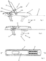
figures 1 and 2 show two different configurations of a fixing system according to the present invention; -
figure 3 shows a view from above of the fixing system offigures 1 and 2 ; -
figure 4 shows a sectional view according to the sectional plane offigure 3 ; -
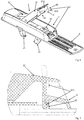
figure 5 shows an exploded view of the fixing system offigures 1-4 ; -
figure 6 shows a perspective view of a fixing system according to the present invention; -
figure 7 shows a sectioned detail of the fixing system offigure 6 ; -
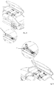
figures 8 and 9 show a rooftop box with a fixing system highlighted according to the present invention in two distinct configurations. - In the appended figures,
reference number 1 denotes a system for removably fixing a cross-bar rooftop box for a vehicle. Thefixing system 1 conveniently comprises agripping means 2. This gripping means 2 allows the connection to the cross bar located on the vehicle's roof. Conveniently, the gripping means 2 comprises agripper 20. Thegripper 20 comprises a first and asecond slider first direction 200 so as to allow the grip and release of one of said cross bars of the vehicle. Thisfirst direction 200 is the direction of advancement of the vehicle. Thisfirst direction 200 is therefore orthogonal to the direction of predominant extension of the bar on the roof. Thefirst direction 200 is substantially horizontal. - The
fixing system 1 comprises a quick coupling andrelease lever 3 that causes the movement of thefirst slider 21 to move it closer to/away from thesecond slider 22. - The quick coupling and
release lever 3 preferably comprises a toggle mechanism. Thelever 3 causes a movement of thefirst slider 21. It does not cause a movement of thesecond slider 22. - The
first slider 21, moving closer to thesecond slider 22, is designed to ensure that thegripper 20 grips the cross bar. When thefirst slider 21 moves away from thesecond slider 22, it allows freeing the vehicle's cross bar. This makes it possible to remove the rooftop box. - Conveniently, the
fixing system 1 comprises astructure 4 comprising guide means 40 of thefirst slider 21. Two fins of thefirst slider 21 are inserted in two corresponding grooves formed in thestructure 4. The first slider 21 (if moved by the lever 3) slides with respect to thestructure 4 along said grooves. The two grooves are advantageously formed on opposite sides of thefirst slider 21. - The
structure 4 comprises an open bottom. Moreover, thestructure 4 comprises two side walls. They extend along thefirst direction 200. The two side walls also extend between the top and the bottom. Ahousing 42 is defined between them. The top of thishousing 42 is intended to be at least partially occluded by thelever 3. - The
fixing system 1 comprises afixing base 5 for fixing inside the rooftop box with which saidstructure 4 can move. It is in communication with thehousing 42 since the bottom of thestructure 4 is open. - The
fixing base 5 can for example be connected to a wall of the rooftop box through threaded means or interlocking means or bayonet means. For example, thefixing base 5 can comprise one or more holes intended for the passage of threaded fixing means for the connection with the box. Both the first and thesecond slider structure 4, crossing thebase 5 intended to come into contact with the supporting cross bar of the box and a support of said arm. This support remains inside thehousing 42. - The
fixing system 1 comprises clamping means 6 which lock/unlock the position along said first direction 200: - i) of said
second slider 22 with respect to thestructure 4; this allows it to adapt to the width along thefirst direction 200 of a cross bar; - ii) of said
structure 4 with respect to saidfixing base 5; this allows it to adapt to the distance along thefirst direction 200 between the two cross bars to which the box is constrained. - The action of the
lever 3 is independent from that of the clamping means 6. Therefore, regardless of the position taken by thelever 3, the clamping means 6, if locked, maintains the position of thesecond slider 22 fixed with respect to thestructure 4 and the position of thestructure 4 with respect to thefixing base 5. The movement of thelever 3 does not cause a movement of thesecond slider 22 with respect to thestructure 4, nor does a movement of thestructure 4 with respect to thefixing base 5. - The clamping means 6 therefore allows memorising a predefined condition to which it is associated both with a predetermined width along the
first direction 200 of a cross bar and the distance along thefirst direction 200 between two cross bars to which the box is constrained. The action of thelever 3 allows a quick coupling or release, but not modifying the memorisation of such a predefined condition. - In the preferred embodiment the clamping means 6 comprises a
clamping screw 60 which acts transversely to saidfirst direction 200. - The
clamping screw 60 extends orthogonally to thefixing base 5. In particular, it is vertical. The clamping means 6 conveniently comprises anut 61 which is screwed to said clampingscrew 60. In one operating configuration a portion of saidsecond slider 22, a portion of saidstructure 4 and a portion of the fixingbase 5 are trapped between a head of the clampingscrew 60 and thenut 61. Thisnut 61 is advantageously housed inside the structure 4 (in particular in the housing 42). Once the clamping means 6 is disconnected/loosened, thesecond slider 22 can be moved along thefirst direction 200 relative to thestructure 4. Similarly once the clamping means 6 is disconnected/loosened, thestructure 4 can be moved along thefirst direction 200 relative to thebase 5. This movement takes place by manually moving thesecond slider 22 or thestructure 4. There is no specific kinematic motion which determines its movement. The fixingbase 5 is flat. The fixingbase 5 conveniently has a two-dimensional extension. Thus it has a reduced thickness compared to the other two dimensions. - The fixing
base 5 comprises aslot 50. In particular, theslot 50 crosses the thickness of thebase 5. Theslot 50 is crossed by thesecond slider 22. Thesecond slider 22 is adjustable relative to thebase 5 along saidslot 50. Theslot 50 preponderantly extends along thefirst direction 200. - The
slot 50 is crossed by thefirst slider 21. Thefirst slider 21, activated by the coupling andrelease lever 3, is slidable along theslot 50. - The
slot 50 is a guide for the first and/orsecond slider slot 50 can conveniently be at least partially occluded by aflexible seal 51. Thisseal 51 allows the passage and the eventual sliding of the first and/orsecond slider - Preferably the
structure 4 and the fixingbase 5 comprise first, opposite grippingteeth 71 that engage to each other upon the clamping of said clampingscrew 60. - The
second slider 22 and said fixingbase 5 comprise second, opposite grippingteeth 72 that engage to each other upon the clamping of said clampingscrew 60. - The first and/or second
gripping teeth - The first
gripping teeth 71 extend in succession side by side along thefirst direction 200. The secondgripping teeth 72 conveniently extend in succession side by side along thefirst direction 200. - Conveniently on the side opposite said fixing
base 5, saidlever 3 and saidfirst slider 21 define a flattop surface 41. In a closed configuration of thegripping means 2 the top 41 is conveniently parallel to thebase 5. - The
lever 3 comprises afirst arm 31 hinged to thestructure 4. This takes place through afirst hinge 310. Thelever 3 also comprises asecond arm 32 hinged to the first arm 31 (advantageously through a second hinge 320) and the first slider 21 (advantageously though a third hinge 330). In a configuration in which thegripping means 2 is closed (meaning it grips the cross bar), thefirst hinge 310 is interposed between the second and the third hinges 320, 330. In a configuration in which thegripping means 2 is at the opening stroke end, thesecond hinge 320 is located at a greater distance from thebase 5 relative to the first andthird hinges first slider 21, an axis of rotation of thefirst hinge 310 remains fixed. During an opening and closing stroke of thefirst slider 21, an axis of rotation of thethird hinge 330 moves along thefirst direction 200. - The fixing
system 1 illustrated as an example infigures 6 and 7 shows alocking system 8 of thelever 3 in a clamping configuration of thegripping means 2. This is a safety measure. In fact, it serves to prevent jolts of the vehicle or an accidental overturning of the load present in the rooftop box from causing an undesired lifting of thelever 3. In this regard, thelocking system 8 comprises means 80 which are elastically deformable; the lever 3 (in particular the first arm 31) and thestructure 4 are mutually connected by such elastically deformable means 80. Thelocking system 8 comprises elastically flexible coupling means 81 rigidly coupled to thelever 3 and one ormore seats 82 defined by thestructure 4; the coupling means 81 are elastically connectable to said one ormore seats 82. The coupling means 81 comprises an invitation that allows the insertion ofsuch means 81 in said one ormore seats 82 upon the closure of thelever 3. The coupling means 81 is located at one end of thelever 3, along a side wall. In particular, the coupling means 81 comprises twohooks seats 82. The twohooks panel 813; a pressure on thepanel 813 causes the exit of thehooks seats 82 and an unlocking of thelever 3. - An object of the present invention is also a rooftop box comprising a plurality of fixing systems 1 (preferably four) having one or more of the properties indicated above. An object of the present invention is also a vehicle comprising a front bar and a rear bar that are placed on the roof of a passenger compartment transversely to the direction of travel. A rooftop box is connected through two fixing systems to the front bar and through two fixing systems to the rear bar.
- The present invention achieves important advantages.
- Firstly, it allows optimising the adaptability of the fixing system to transverse bars of different widths or otherwise placed at a different distance. If also allows faster connection and release, which is very important for this type of application. Another important advantage is safety in order to prevent accidental and unwanted unlocking of the fixing system that would jeopardise road safety.
- The invention as it is conceived is susceptible to numerous modifications and variations, all falling within the scope of the inventive concept characterising it. Furthermore, all the details can be replaced by other technically equivalent elements. In practice, all the materials used, as well as the dimensions, can be any according to requirements.
Claims (10)
- A system for removably fixing a cross-bar rooftop box for a vehicle, comprising:- gripping means (2) comprising a gripper (20) in turn comprising a first and a second slider (21, 22) which can be moved toward and away from each other with respect to a first direction (200) so as to allow the grip and release of one of said cross bars of the vehicle;- a quick coupling and release lever (3) that causes the movement of the first slider (21) to move it closer to/away from the second slider (22);- a structure (4) comprising guide means (40) for guiding the movement of the first slider (21);- a fixing base (5) for fixing inside the rooftop box with which said structure (4) can move;- clamping means (6) which, independently from the lever (3), lock/unlock the position along said first direction (200):i) of said second slider (22) with respect to the structure in order to adapt to the width along the first direction (200) of a cross bar;ii) of said structure (4) with respect to said fixing base (5) in order to adapt to the distance along the first direction (200) between the two cross bars to which the box is constrained.
- The system according to claim 1, characterised in that said clamping means (6) comprise a clamping screw (60) which acts transversely to said first direction (200).
- The system according to claim 2, characterised in that the clamping screw (60) extends orthogonally to the fixing base (5).
- The system according to any one of the preceding claims, characterised in that said fixing base (5) comprises a slit (50) crossed by said second slider (22), said second slider (22) being adjustable relative to the base (5) along said slot (50).
- The system according to claim 4, characterised in that the slot (50) is crossed by the first slider (21), the first slider (21), actuated by the coupling and release lever (3), is slidable along the slot (50).
- The system according to claim 4 or 5, characterised in that the slot (50) is a guide for the first and/or second slider (21, 22).
- The system according to any one of the preceding claims, characterised in that said structure (4) and said fixing base (5) comprise first, opposite gripping teeth (71) that engage to each other upon the clamping of said clamping means (6);
said second slider (22) and said fixing base (5) comprise second, opposite gripping teeth (72) that engage to each other upon the clamping of said clamping means (6). - The system according to any one of the preceding claims, characterised in that said quick coupling and release lever (3) comprises a toggle mechanism.
- The system according to any one of the preceding claims, characterised in that on the side opposite said fixing base (5), said lever (3) and said first slider (21) define a flat top surface (41).
- The system according to any one of the preceding claims, characterised in that said fixing base (5) is flat.
Applications Claiming Priority (1)
| Application Number | Priority Date | Filing Date | Title |
|---|---|---|---|
| IT201800009271 | 2018-10-09 |
Publications (2)
| Publication Number | Publication Date |
|---|---|
| EP3659865A1 true EP3659865A1 (en) | 2020-06-03 |
| EP3659865B1 EP3659865B1 (en) | 2020-09-23 |
Family
ID=65324428
Family Applications (1)
| Application Number | Title | Priority Date | Filing Date |
|---|---|---|---|
| EP19201832.3A Active EP3659865B1 (en) | 2018-10-09 | 2019-10-08 | System for removably fixing a vehicle rooftop box |
Country Status (1)
| Country | Link |
|---|---|
| EP (1) | EP3659865B1 (en) |
Cited By (1)
| Publication number | Priority date | Publication date | Assignee | Title |
|---|---|---|---|---|
| US20200391665A1 (en) * | 2019-06-17 | 2020-12-17 | The Eastern Company | Vehicle Roof Rack Accessory Clamp |
Families Citing this family (1)
| Publication number | Priority date | Publication date | Assignee | Title |
|---|---|---|---|---|
| DE102023122844A1 (en) * | 2023-08-25 | 2025-02-27 | BOS Technology Services GmbH | fastening system for a load carrier |
Citations (3)
| Publication number | Priority date | Publication date | Assignee | Title |
|---|---|---|---|---|
| EP2443006B1 (en) * | 2009-06-15 | 2014-08-13 | Yakima Products, Inc. | Crossbar clamp devices |
| EP2536593B1 (en) * | 2010-02-18 | 2015-08-26 | Mont Blanc Industri AB | Fastening assembly for a roof box |
| WO2018104684A1 (en) * | 2016-12-09 | 2018-06-14 | Brochier Patrice | Attachment device, supporting accessory and roof tent including such a device |
-
2019
- 2019-10-08 EP EP19201832.3A patent/EP3659865B1/en active Active
Patent Citations (3)
| Publication number | Priority date | Publication date | Assignee | Title |
|---|---|---|---|---|
| EP2443006B1 (en) * | 2009-06-15 | 2014-08-13 | Yakima Products, Inc. | Crossbar clamp devices |
| EP2536593B1 (en) * | 2010-02-18 | 2015-08-26 | Mont Blanc Industri AB | Fastening assembly for a roof box |
| WO2018104684A1 (en) * | 2016-12-09 | 2018-06-14 | Brochier Patrice | Attachment device, supporting accessory and roof tent including such a device |
Cited By (2)
| Publication number | Priority date | Publication date | Assignee | Title |
|---|---|---|---|---|
| US20200391665A1 (en) * | 2019-06-17 | 2020-12-17 | The Eastern Company | Vehicle Roof Rack Accessory Clamp |
| US11772567B2 (en) * | 2019-06-17 | 2023-10-03 | The Eastern Company | Vehicle roof rack accessory clamp |
Also Published As
| Publication number | Publication date |
|---|---|
| EP3659865B1 (en) | 2020-09-23 |
Similar Documents
| Publication | Publication Date | Title |
|---|---|---|
| US6053560A (en) | Convertible vehicle | |
| US8807407B2 (en) | Clamping assembly for a roof box carrier having an adjustment mechanism | |
| US7992912B2 (en) | Loading base for motor vehicles | |
| US6402217B1 (en) | Easy-to-use roller blind | |
| US20170158254A1 (en) | Pick up truck elongator | |
| EP3659865B1 (en) | System for removably fixing a vehicle rooftop box | |
| US9211842B2 (en) | Cargo floor for a vehicle | |
| HU221443B (en) | Sliding partition | |
| KR20160025463A (en) | Container receiving apparatus for a vehicle interior | |
| US2743773A (en) | Two-door automobile with folding doors | |
| DE19534436A1 (en) | Glove pocket for dashboard | |
| WO2020143956A1 (en) | Drive system for a roof spoiler system of a motor vehicle | |
| US4993771A (en) | Truck trunk device | |
| KR20140112859A (en) | storage apparatus of automobile and partition using the same | |
| EP3647094B1 (en) | Roof system for a vehicle | |
| CN114206675A (en) | Automobile accessory | |
| DE102005055188A1 (en) | Motor vehicle, has luggage compartment cover adjustable from one position to another position and moved from latter position into third position, where cover is extended into third position over trunk sill | |
| EP0888917B1 (en) | Open roof construction for a vehicle | |
| EP1010581A2 (en) | Device for fastening functional units in a vehicle luggage compartment, and parcel shelf therefor | |
| NL1011154C2 (en) | Folding roof for a vehicle. | |
| AU2006289511B9 (en) | Vehicle roof with at least two cover elements | |
| DE102008019394B4 (en) | Cargo space for a motor vehicle | |
| US20240059227A1 (en) | Storage Element | |
| EP2008848B1 (en) | Motor vehicle roof | |
| CN117360228A (en) | Reversible sub-instrument panel and vehicle |
Legal Events
| Date | Code | Title | Description |
|---|---|---|---|
| PUAI | Public reference made under article 153(3) epc to a published international application that has entered the european phase |
Free format text: ORIGINAL CODE: 0009012 |
|
| STAA | Information on the status of an ep patent application or granted ep patent |
Free format text: STATUS: THE APPLICATION HAS BEEN PUBLISHED |
|
| STAA | Information on the status of an ep patent application or granted ep patent |
Free format text: STATUS: REQUEST FOR EXAMINATION WAS MADE |
|
| AK | Designated contracting states |
Kind code of ref document: A1 Designated state(s): AL AT BE BG CH CY CZ DE DK EE ES FI FR GB GR HR HU IE IS IT LI LT LU LV MC MK MT NL NO PL PT RO RS SE SI SK SM TR |
|
| AX | Request for extension of the european patent |
Extension state: BA ME |
|
| 17P | Request for examination filed |
Effective date: 20200527 |
|
| RBV | Designated contracting states (corrected) |
Designated state(s): AL AT BE BG CH CY CZ DE DK EE ES FI FR GB GR HR HU IE IS IT LI LT LU LV MC MK MT NL NO PL PT RO RS SE SI SK SM TR |
|
| GRAP | Despatch of communication of intention to grant a patent |
Free format text: ORIGINAL CODE: EPIDOSNIGR1 |
|
| STAA | Information on the status of an ep patent application or granted ep patent |
Free format text: STATUS: GRANT OF PATENT IS INTENDED |
|
| GRAS | Grant fee paid |
Free format text: ORIGINAL CODE: EPIDOSNIGR3 |
|
| INTG | Intention to grant announced |
Effective date: 20200714 |
|
| GRAA | (expected) grant |
Free format text: ORIGINAL CODE: 0009210 |
|
| STAA | Information on the status of an ep patent application or granted ep patent |
Free format text: STATUS: THE PATENT HAS BEEN GRANTED |
|
| AK | Designated contracting states |
Kind code of ref document: B1 Designated state(s): AL AT BE BG CH CY CZ DE DK EE ES FI FR GB GR HR HU IE IS IT LI LT LU LV MC MK MT NL NO PL PT RO RS SE SI SK SM TR |
|
| REG | Reference to a national code |
Ref country code: GB Ref legal event code: FG4D |
|
| REG | Reference to a national code |
Ref country code: CH Ref legal event code: EP |
|
| REG | Reference to a national code |
Ref country code: IE Ref legal event code: FG4D |
|
| REG | Reference to a national code |
Ref country code: DE Ref legal event code: R096 Ref document number: 602019000775 Country of ref document: DE Ref country code: AT Ref legal event code: REF Ref document number: 1316079 Country of ref document: AT Kind code of ref document: T Effective date: 20201015 |
|
| REG | Reference to a national code |
Ref country code: NL Ref legal event code: FP |
|
| PG25 | Lapsed in a contracting state [announced via postgrant information from national office to epo] |
Ref country code: NO Free format text: LAPSE BECAUSE OF FAILURE TO SUBMIT A TRANSLATION OF THE DESCRIPTION OR TO PAY THE FEE WITHIN THE PRESCRIBED TIME-LIMIT Effective date: 20201223 Ref country code: GR Free format text: LAPSE BECAUSE OF FAILURE TO SUBMIT A TRANSLATION OF THE DESCRIPTION OR TO PAY THE FEE WITHIN THE PRESCRIBED TIME-LIMIT Effective date: 20201224 Ref country code: HR Free format text: LAPSE BECAUSE OF FAILURE TO SUBMIT A TRANSLATION OF THE DESCRIPTION OR TO PAY THE FEE WITHIN THE PRESCRIBED TIME-LIMIT Effective date: 20200923 Ref country code: BG Free format text: LAPSE BECAUSE OF FAILURE TO SUBMIT A TRANSLATION OF THE DESCRIPTION OR TO PAY THE FEE WITHIN THE PRESCRIBED TIME-LIMIT Effective date: 20201223 Ref country code: FI Free format text: LAPSE BECAUSE OF FAILURE TO SUBMIT A TRANSLATION OF THE DESCRIPTION OR TO PAY THE FEE WITHIN THE PRESCRIBED TIME-LIMIT Effective date: 20200923 Ref country code: SE Free format text: LAPSE BECAUSE OF FAILURE TO SUBMIT A TRANSLATION OF THE DESCRIPTION OR TO PAY THE FEE WITHIN THE PRESCRIBED TIME-LIMIT Effective date: 20200923 |
|
| REG | Reference to a national code |
Ref country code: AT Ref legal event code: MK05 Ref document number: 1316079 Country of ref document: AT Kind code of ref document: T Effective date: 20200923 |
|
| PG25 | Lapsed in a contracting state [announced via postgrant information from national office to epo] |
Ref country code: LV Free format text: LAPSE BECAUSE OF FAILURE TO SUBMIT A TRANSLATION OF THE DESCRIPTION OR TO PAY THE FEE WITHIN THE PRESCRIBED TIME-LIMIT Effective date: 20200923 Ref country code: RS Free format text: LAPSE BECAUSE OF FAILURE TO SUBMIT A TRANSLATION OF THE DESCRIPTION OR TO PAY THE FEE WITHIN THE PRESCRIBED TIME-LIMIT Effective date: 20200923 |
|
| REG | Reference to a national code |
Ref country code: LT Ref legal event code: MG4D |
|
| PG25 | Lapsed in a contracting state [announced via postgrant information from national office to epo] |
Ref country code: SM Free format text: LAPSE BECAUSE OF FAILURE TO SUBMIT A TRANSLATION OF THE DESCRIPTION OR TO PAY THE FEE WITHIN THE PRESCRIBED TIME-LIMIT Effective date: 20200923 Ref country code: LT Free format text: LAPSE BECAUSE OF FAILURE TO SUBMIT A TRANSLATION OF THE DESCRIPTION OR TO PAY THE FEE WITHIN THE PRESCRIBED TIME-LIMIT Effective date: 20200923 Ref country code: EE Free format text: LAPSE BECAUSE OF FAILURE TO SUBMIT A TRANSLATION OF THE DESCRIPTION OR TO PAY THE FEE WITHIN THE PRESCRIBED TIME-LIMIT Effective date: 20200923 Ref country code: CZ Free format text: LAPSE BECAUSE OF FAILURE TO SUBMIT A TRANSLATION OF THE DESCRIPTION OR TO PAY THE FEE WITHIN THE PRESCRIBED TIME-LIMIT Effective date: 20200923 Ref country code: PT Free format text: LAPSE BECAUSE OF FAILURE TO SUBMIT A TRANSLATION OF THE DESCRIPTION OR TO PAY THE FEE WITHIN THE PRESCRIBED TIME-LIMIT Effective date: 20210125 Ref country code: RO Free format text: LAPSE BECAUSE OF FAILURE TO SUBMIT A TRANSLATION OF THE DESCRIPTION OR TO PAY THE FEE WITHIN THE PRESCRIBED TIME-LIMIT Effective date: 20200923 |
|
| PG25 | Lapsed in a contracting state [announced via postgrant information from national office to epo] |
Ref country code: AT Free format text: LAPSE BECAUSE OF FAILURE TO SUBMIT A TRANSLATION OF THE DESCRIPTION OR TO PAY THE FEE WITHIN THE PRESCRIBED TIME-LIMIT Effective date: 20200923 Ref country code: AL Free format text: LAPSE BECAUSE OF FAILURE TO SUBMIT A TRANSLATION OF THE DESCRIPTION OR TO PAY THE FEE WITHIN THE PRESCRIBED TIME-LIMIT Effective date: 20200923 Ref country code: ES Free format text: LAPSE BECAUSE OF FAILURE TO SUBMIT A TRANSLATION OF THE DESCRIPTION OR TO PAY THE FEE WITHIN THE PRESCRIBED TIME-LIMIT Effective date: 20200923 Ref country code: PL Free format text: LAPSE BECAUSE OF FAILURE TO SUBMIT A TRANSLATION OF THE DESCRIPTION OR TO PAY THE FEE WITHIN THE PRESCRIBED TIME-LIMIT Effective date: 20200923 Ref country code: IS Free format text: LAPSE BECAUSE OF FAILURE TO SUBMIT A TRANSLATION OF THE DESCRIPTION OR TO PAY THE FEE WITHIN THE PRESCRIBED TIME-LIMIT Effective date: 20210123 |
|
| REG | Reference to a national code |
Ref country code: DE Ref legal event code: R097 Ref document number: 602019000775 Country of ref document: DE |
|
| PG25 | Lapsed in a contracting state [announced via postgrant information from national office to epo] |
Ref country code: SK Free format text: LAPSE BECAUSE OF FAILURE TO SUBMIT A TRANSLATION OF THE DESCRIPTION OR TO PAY THE FEE WITHIN THE PRESCRIBED TIME-LIMIT Effective date: 20200923 Ref country code: MC Free format text: LAPSE BECAUSE OF FAILURE TO SUBMIT A TRANSLATION OF THE DESCRIPTION OR TO PAY THE FEE WITHIN THE PRESCRIBED TIME-LIMIT Effective date: 20200923 |
|
| PLBE | No opposition filed within time limit |
Free format text: ORIGINAL CODE: 0009261 |
|
| STAA | Information on the status of an ep patent application or granted ep patent |
Free format text: STATUS: NO OPPOSITION FILED WITHIN TIME LIMIT |
|
| PG25 | Lapsed in a contracting state [announced via postgrant information from national office to epo] |
Ref country code: DK Free format text: LAPSE BECAUSE OF FAILURE TO SUBMIT A TRANSLATION OF THE DESCRIPTION OR TO PAY THE FEE WITHIN THE PRESCRIBED TIME-LIMIT Effective date: 20200923 |
|
| 26N | No opposition filed |
Effective date: 20210624 |
|
| PG25 | Lapsed in a contracting state [announced via postgrant information from national office to epo] |
Ref country code: IT Free format text: LAPSE BECAUSE OF FAILURE TO SUBMIT A TRANSLATION OF THE DESCRIPTION OR TO PAY THE FEE WITHIN THE PRESCRIBED TIME-LIMIT Effective date: 20200923 |
|
| PG25 | Lapsed in a contracting state [announced via postgrant information from national office to epo] |
Ref country code: TR Free format text: LAPSE BECAUSE OF FAILURE TO SUBMIT A TRANSLATION OF THE DESCRIPTION OR TO PAY THE FEE WITHIN THE PRESCRIBED TIME-LIMIT Effective date: 20200923 |
|
| REG | Reference to a national code |
Ref country code: BE Ref legal event code: MM Effective date: 20211031 |
|
| PG25 | Lapsed in a contracting state [announced via postgrant information from national office to epo] |
Ref country code: LU Free format text: LAPSE BECAUSE OF NON-PAYMENT OF DUE FEES Effective date: 20211008 Ref country code: BE Free format text: LAPSE BECAUSE OF NON-PAYMENT OF DUE FEES Effective date: 20211031 |
|
| PG25 | Lapsed in a contracting state [announced via postgrant information from national office to epo] |
Ref country code: IE Free format text: LAPSE BECAUSE OF NON-PAYMENT OF DUE FEES Effective date: 20211008 |
|
| REG | Reference to a national code |
Ref country code: CH Ref legal event code: PL |
|
| P01 | Opt-out of the competence of the unified patent court (upc) registered |
Effective date: 20230517 |
|
| PG25 | Lapsed in a contracting state [announced via postgrant information from national office to epo] |
Ref country code: CY Free format text: LAPSE BECAUSE OF FAILURE TO SUBMIT A TRANSLATION OF THE DESCRIPTION OR TO PAY THE FEE WITHIN THE PRESCRIBED TIME-LIMIT Effective date: 20200923 |
|
| PG25 | Lapsed in a contracting state [announced via postgrant information from national office to epo] |
Ref country code: LI Free format text: LAPSE BECAUSE OF NON-PAYMENT OF DUE FEES Effective date: 20221031 Ref country code: CH Free format text: LAPSE BECAUSE OF NON-PAYMENT OF DUE FEES Effective date: 20221031 |
|
| PG25 | Lapsed in a contracting state [announced via postgrant information from national office to epo] |
Ref country code: SI Free format text: LAPSE BECAUSE OF FAILURE TO SUBMIT A TRANSLATION OF THE DESCRIPTION OR TO PAY THE FEE WITHIN THE PRESCRIBED TIME-LIMIT Effective date: 20200923 |
|
| PG25 | Lapsed in a contracting state [announced via postgrant information from national office to epo] |
Ref country code: MK Free format text: LAPSE BECAUSE OF FAILURE TO SUBMIT A TRANSLATION OF THE DESCRIPTION OR TO PAY THE FEE WITHIN THE PRESCRIBED TIME-LIMIT Effective date: 20200923 |
|
| GBPC | Gb: european patent ceased through non-payment of renewal fee |
Effective date: 20231008 |
|
| PG25 | Lapsed in a contracting state [announced via postgrant information from national office to epo] |
Ref country code: GB Free format text: LAPSE BECAUSE OF NON-PAYMENT OF DUE FEES Effective date: 20231008 |
|
| PG25 | Lapsed in a contracting state [announced via postgrant information from national office to epo] |
Ref country code: GB Free format text: LAPSE BECAUSE OF NON-PAYMENT OF DUE FEES Effective date: 20231008 |
|
| PG25 | Lapsed in a contracting state [announced via postgrant information from national office to epo] |
Ref country code: MT Free format text: LAPSE BECAUSE OF FAILURE TO SUBMIT A TRANSLATION OF THE DESCRIPTION OR TO PAY THE FEE WITHIN THE PRESCRIBED TIME-LIMIT Effective date: 20200923 |
|
| PGFP | Annual fee paid to national office [announced via postgrant information from national office to epo] |
Ref country code: NL Payment date: 20241023 Year of fee payment: 6 |
|
| PGFP | Annual fee paid to national office [announced via postgrant information from national office to epo] |
Ref country code: DE Payment date: 20241029 Year of fee payment: 6 |
|
| PGFP | Annual fee paid to national office [announced via postgrant information from national office to epo] |
Ref country code: FR Payment date: 20241025 Year of fee payment: 6 |