EP3659736A1 - Method to join materials with a different melting temperature - Google Patents
Method to join materials with a different melting temperature Download PDFInfo
- Publication number
- EP3659736A1 EP3659736A1 EP19211938.6A EP19211938A EP3659736A1 EP 3659736 A1 EP3659736 A1 EP 3659736A1 EP 19211938 A EP19211938 A EP 19211938A EP 3659736 A1 EP3659736 A1 EP 3659736A1
- Authority
- EP
- European Patent Office
- Prior art keywords
- melting temperature
- grooves
- materials
- joining
- during
- Prior art date
- Legal status (The legal status is an assumption and is not a legal conclusion. Google has not performed a legal analysis and makes no representation as to the accuracy of the status listed.)
- Granted
Links
Images
Classifications
-
- B—PERFORMING OPERATIONS; TRANSPORTING
- B23—MACHINE TOOLS; METAL-WORKING NOT OTHERWISE PROVIDED FOR
- B23K—SOLDERING OR UNSOLDERING; WELDING; CLADDING OR PLATING BY SOLDERING OR WELDING; CUTTING BY APPLYING HEAT LOCALLY, e.g. FLAME CUTTING; WORKING BY LASER BEAM
- B23K11/00—Resistance welding; Severing by resistance heating
- B23K11/10—Spot welding; Stitch welding
- B23K11/11—Spot welding
- B23K11/115—Spot welding by means of two electrodes placed opposite one another on both sides of the welded parts
-
- B—PERFORMING OPERATIONS; TRANSPORTING
- B23—MACHINE TOOLS; METAL-WORKING NOT OTHERWISE PROVIDED FOR
- B23K—SOLDERING OR UNSOLDERING; WELDING; CLADDING OR PLATING BY SOLDERING OR WELDING; CUTTING BY APPLYING HEAT LOCALLY, e.g. FLAME CUTTING; WORKING BY LASER BEAM
- B23K11/00—Resistance welding; Severing by resistance heating
- B23K11/16—Resistance welding; Severing by resistance heating taking account of the properties of the material to be welded
- B23K11/20—Resistance welding; Severing by resistance heating taking account of the properties of the material to be welded of different metals
-
- B—PERFORMING OPERATIONS; TRANSPORTING
- B23—MACHINE TOOLS; METAL-WORKING NOT OTHERWISE PROVIDED FOR
- B23K—SOLDERING OR UNSOLDERING; WELDING; CLADDING OR PLATING BY SOLDERING OR WELDING; CUTTING BY APPLYING HEAT LOCALLY, e.g. FLAME CUTTING; WORKING BY LASER BEAM
- B23K26/00—Working by laser beam, e.g. welding, cutting or boring
- B23K26/36—Removing material
- B23K26/38—Removing material by boring or cutting
Definitions
- the present invention concerns a method to mechanically join materials with a different melting temperature.
- the present invention concerns the mechanical joining of electrically conductive materials which can have very different melting temperatures.
- Multi-material hybrid structures are used in a vast range of applications including transport, electronics, and in the civil and biomedical fields. In fact, the possibility of combining different materials results in improved performance of the resulting structure. In this context there is the need to effectively join materials characterized by very different mechanical, physical and thermal characteristics.
- This type of joint is generally obtained by means of two types of processes: adhesive joints and/or mechanical joints.
- adhesive joints show a high resistance to shear stress, and poor resistance to peeling stress.
- the edge to be joined is appropriately shaped in order to increase the performance of the adhesive joints.
- the adhesive joints furthermore require long and costly surface pre-treatments. Said processes can be either mechanical (removal of the surface layer by means of metal brushes, sandblasting etc.) or chemical (use of solvents) and can also entail a significant environmental impact.
- the conventional welding processes e.g. spot welding
- the conventional welding processes do not allow joints to be made between metallic materials with different melting temperatures, since only one of the materials is brought to melting point.
- the inventors of the present invention have provided a method of joining conductor materials at different melting temperatures, which entails the creation of a plurality of grooves on the surface of the material with a higher melting temperature.
- the subject of the present invention is a method for producing a mechanical joint between two conductor materials with different melting temperatures; said method being characterized by the fact of comprising in succession
- the method comprises a preliminary cutting step, wherein a plurality of said grooves is provided on the surface of the material with higher melting point.
- said joining step is carried out by means of a resistance welding, even more preferably by means of a spot welding.
- said cutting step is carried out by means of a laser technique.
- the method subject of the present invention was carried out by coupling an aluminium alloy sheet 1 (AA7075) and a titanium sheet 2 (grade 2).
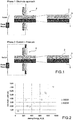
- the sheets 1 and 2 of the two materials (both having thickness of 2 mm) were joined by overlap, as shown in Fig. 2 .
- a plurality of grooves 3 were made by means of a pulsed fibre laser (YLP-RA30-1-50-20-20 by IPG) as shown in Fig. 1 .
- the plurality of grooves resulted in a square texture using the following process parameters:
- the joining step was carried out by means of a spot welder 4 and copper electrodes with diameter of 10 mm.
- An experimental test program was carried out in which both the power was varied between 300W and 600W and the welding duration between 0.2 and 1.5 s.
- traction tests were carried out to evaluate the mechanical characteristics of the joints.
- a universal test machine model 322.121 by MTS was used equipped with a loading cell with capacity of 25 kN.
- the joining mechanism is based on heating of the material with a lower melting temperature and penetration thereof into the grooves made (or already present) in the material with a higher melting temperature.
Landscapes
- Engineering & Computer Science (AREA)
- Mechanical Engineering (AREA)
- Physics & Mathematics (AREA)
- Optics & Photonics (AREA)
- Plasma & Fusion (AREA)
- Pressure Welding/Diffusion-Bonding (AREA)
- Laser Beam Processing (AREA)
- Ceramic Products (AREA)
- Manufacture Of Switches (AREA)
Abstract
- a contact step, during which a surface of a material with a higher melting temperature, where there are grooves, is arranged in contact with a surface of a material with a lower melting temperature, and
- a joining step, during which the two materials are subjected to a coupling pressure and, at the same time, are crossed through by a current at the plurality of grooves until the grooves are filled with said material with a lower melting temperature.;
said grooves having an undercut profile.
Description
- This Patent Application claims priority from Italian Patent Application No.
102018000010611 filed on November 27, 2018 - The present invention concerns a method to mechanically join materials with a different melting temperature.
- In particular, the present invention concerns the mechanical joining of electrically conductive materials which can have very different melting temperatures.
- Multi-material hybrid structures are used in a vast range of applications including transport, electronics, and in the civil and biomedical fields. In fact, the possibility of combining different materials results in improved performance of the resulting structure. In this context there is the need to effectively join materials characterized by very different mechanical, physical and thermal characteristics.
- This type of joint is generally obtained by means of two types of processes: adhesive joints and/or mechanical joints. Although commonly adopted, both these solutions have drawbacks. For example, adhesive joints show a high resistance to shear stress, and poor resistance to peeling stress. To remedy this problem, the edge to be joined is appropriately shaped in order to increase the performance of the adhesive joints. The adhesive joints furthermore require long and costly surface pre-treatments. Said processes can be either mechanical (removal of the surface layer by means of metal brushes, sandblasting etc.) or chemical (use of solvents) and can also entail a significant environmental impact.
- Furthermore, in the long term the mechanical characteristics of the adhesive joints are characterized by a high variability and uncertainty.
- On the other hand, mechanical joints (riveting, bolting etc.), although widely used in the aeronautical and naval industries, have several limits and problems, including the presence of spot joints around which stress is concentrated, and the adoption of external elements for the joint which result in increased weight of the structure and increased costs.
- Furthermore, the majority of mechanical joining processes require preliminary drilling of the metal sheets. Said additional process, in addition to representing a problem in terms of productivity (costs and times), can damage the components.
- In recent years, various alternative solutions have been proposed to overcome the above-mentioned limits, which entail the functionalization of one or both of the surfaces to be joined and subsequent thermal-mechanical joining. Processes such as laser assisted joining and friction assisted joining have been used to join different types of materials (metal-thermoplastic, metal-composite). In recent years, these processes have been adapted to produce hybrid joints between different metals. However, said solutions are not yet able to provide satisfactory results in terms of mechanical characteristics and production times. Said problems are even more evident when materials characterized by high thermal conductivity (e.g. aluminium) are joined, in which a large part of the heat is ceded to the surrounding areas.
- As is known to a person skilled in the art, the conventional welding processes (e.g. spot welding) do not allow joints to be made between metallic materials with different melting temperatures, since only one of the materials is brought to melting point.
- The need was therefore felt for a solution able to join materials with different melting temperatures without the problems of the known art.
- The inventors of the present invention have provided a method of joining conductor materials at different melting temperatures, which entails the creation of a plurality of grooves on the surface of the material with a higher melting temperature.
- The subject of the present invention is a method for producing a mechanical joint between two conductor materials with different melting temperatures; said method being characterized by the fact of comprising in succession
- a contact step, wherein a surface, of a material with a higher melting temperature where grooves are present, is arranged in contact with a surface of a material with a lower melting temperature, and
- a joining step, wherein the two materials are subjected to a coupling pressure and, at the same time, are crossed through by a current at the plurality of grooves until the grooves are filled by said material with a lower melting temperature; said grooves (3) having an undercut profile.
- It has been experimentally proved that the invention of the present invention is effective even when the difference in the melting point between the two materials is only a few °C.
- Preferably, the method comprises a preliminary cutting step, wherein a plurality of said grooves is provided on the surface of the material with higher melting point.
- Preferably, said joining step is carried out by means of a resistance welding, even more preferably by means of a spot welding.
- Preferably, said cutting step is carried out by means of a laser technique.
- An embodiment example is provided below purely for illustrative non-limiting purposes with the aid of the attached figures, in which:
-
figure 1 illustrates schematically two steps of the method according to the present invention; and -
figure 2 is a graph relative to the traction tests performed for the example given below. - The method subject of the present invention was carried out by coupling an aluminium alloy sheet 1 (AA7075) and a titanium sheet 2 (grade 2). The
sheets Fig. 2 . - The main mechanical and thermal characteristics of the materials are given in Table I.
TABLE I Material Young Modulus [GPa] Yield Strength [MPa] Tensile Strength [MPa] Elongation at rupture [%] Melting Point [°C] Titanium 120 394 450 20 1670 Aluminium 67 468 650 8.4 635 - From Table I the considerable difference between the melting points of the two materials can be seen. This makes any melting-based welding process ineffective.
- On the titanium sheet 2 a plurality of
grooves 3 were made by means of a pulsed fibre laser (YLP-RA30-1-50-20-20 by IPG) as shown inFig. 1 . The plurality of grooves resulted in a square texture using the following process parameters: - pulse frequency: 30 kHz;
- scanning speed: 1000 mm/s;
- hatch distance (distance between two consecutive scanning lines): 0.3 mm;
- 40 repetitions.
- The joining step was carried out by means of a spot welder 4 and copper electrodes with diameter of 10 mm. An experimental test program was carried out in which both the power was varied between 300W and 600W and the welding duration between 0.2 and 1.5 s.
- Subsequently, traction tests were carried out to evaluate the mechanical characteristics of the joints. For said purpose a universal test machine model 322.121 by MTS was used equipped with a loading cell with capacity of 25 kN.
- The results of said traction tests are reported in the graph of figure 3, where it is possible to correlate the joining energy used with the maximum traction load. As is known, the joining energy E was calculated as a product of duration × power.
- From the graph shown in Fig. 3, it can be clearly seen that the strength of the joints reaches very high values (even higher than 7 kN) corresponding to a modulus of rupture of 160 MPa with very short joining times (1.4 s). This shows that the method according to the present invention guarantees the production of joints with very promising mechanical performance. Furthermore, it should be underlined that the method subject of the present invention can be easily implemented and, at the same time, is characterized by a high productivity and reduced energy requirements. Said advantages are due to the low joining times (the heat does not diffuse radially), while the joining area is the one characterized by maximum electrical resistance (due to the presence of the texture which reduces the contact surface).
- As illustrated in
figure 2 , the joining mechanism is based on heating of the material with a lower melting temperature and penetration thereof into the grooves made (or already present) in the material with a higher melting temperature. - Lastly, it is important to note that the particular heating system by passage of current according to the method of the present invention provides the following advantages:
- 1) Very low cycle times linked to the high power and localisation of the heating in the joining area (the presence of the texture reduces the contact surface and increases the electrical resistance of this area).
- 2) Limited thermally altered area and modest residual tensions. Furthermore, in the case of metallic materials, reduced swelling of the grains is obtained due to:
- a. Low heating times;
- b. Low temperatures (it is not necessary to reach the melting temperature but only softening of the low-melting material).
- 3) Low cost of the heating system.
- 4) Easy integration in existing production systems since the welders already present can be used.
Claims (5)
- A method to mechanically join two conductor materials (1, 2) with a different melting temperature; said method being characterized in that it comprises, in succession- a contact step, during which a surface of a material with a higher melting temperature (2), where there are grooves (3), is arranged in contact with a surface of a material with a lower melting temperature (1), and- a joining step, during which the two materials are subjected to a coupling pressure and, at the same time, are crossed through by a current at the plurality of grooves (3) until the grooves (3) are filled with said material with a lower melting temperature;said grooves (3) having an undercut profile.
- The method according to claim 1, characterized in that it comprises a preliminary cutting step, during which a plurality of said grooves (3) are obtained on the surface of the material with a higher melting temperature (2).
- The method according to any one of the preceding claims, characterized in that said joining step is carried out by means of a resistance welding (4).
- The method according to claim 3, characterized in that said resistance welding is a spot welding (4).
- The method according to claim 2, characterized in that said preliminary cutting step is carried out by means of a laser technique.
Priority Applications (1)
| Application Number | Priority Date | Filing Date | Title |
|---|---|---|---|
| PL19211938T PL3659736T3 (en) | 2018-11-27 | 2019-11-27 | Method to join materials with a different melting temperature |
Applications Claiming Priority (1)
| Application Number | Priority Date | Filing Date | Title |
|---|---|---|---|
| IT102018000010611A IT201800010611A1 (en) | 2018-11-27 | 2018-11-27 | METHOD FOR MAKING A MECHANICAL JOINT OF MATERIALS WITH DIFFERENT MELTING TEMPERATURE |
Publications (3)
| Publication Number | Publication Date |
|---|---|
| EP3659736A1 true EP3659736A1 (en) | 2020-06-03 |
| EP3659736A8 EP3659736A8 (en) | 2020-08-05 |
| EP3659736B1 EP3659736B1 (en) | 2022-01-05 |
Family
ID=65576506
Family Applications (1)
| Application Number | Title | Priority Date | Filing Date |
|---|---|---|---|
| EP19211938.6A Active EP3659736B1 (en) | 2018-11-27 | 2019-11-27 | Method to join materials with a different melting temperature |
Country Status (4)
| Country | Link |
|---|---|
| EP (1) | EP3659736B1 (en) |
| ES (1) | ES2909002T3 (en) |
| IT (1) | IT201800010611A1 (en) |
| PL (1) | PL3659736T3 (en) |
Cited By (1)
| Publication number | Priority date | Publication date | Assignee | Title |
|---|---|---|---|---|
| WO2023036800A1 (en) * | 2021-09-07 | 2023-03-16 | Katholieke Universiteit Leuven | Method for producing a resistance welded joint and joint thereof |
Citations (3)
| Publication number | Priority date | Publication date | Assignee | Title |
|---|---|---|---|---|
| DE740695C (en) * | 1937-04-23 | 1943-10-27 | Siemens Ag | Process for joining copper and light metal parts by electrical resistance butt or flash welding |
| US5783794A (en) * | 1993-11-15 | 1998-07-21 | Nippon Steel Corporation | Method and material for resistance welding steel-base metal sheet to aluminum-base metal sheet |
| DE102012000692A1 (en) * | 2011-01-19 | 2012-07-19 | GM Global Technology Operations LLC ( n.d. Ges. d. Staates Delaware) | Resistance spot welding product and method of forming the same. |
-
2018
- 2018-11-27 IT IT102018000010611A patent/IT201800010611A1/en unknown
-
2019
- 2019-11-27 PL PL19211938T patent/PL3659736T3/en unknown
- 2019-11-27 EP EP19211938.6A patent/EP3659736B1/en active Active
- 2019-11-27 ES ES19211938T patent/ES2909002T3/en active Active
Patent Citations (3)
| Publication number | Priority date | Publication date | Assignee | Title |
|---|---|---|---|---|
| DE740695C (en) * | 1937-04-23 | 1943-10-27 | Siemens Ag | Process for joining copper and light metal parts by electrical resistance butt or flash welding |
| US5783794A (en) * | 1993-11-15 | 1998-07-21 | Nippon Steel Corporation | Method and material for resistance welding steel-base metal sheet to aluminum-base metal sheet |
| DE102012000692A1 (en) * | 2011-01-19 | 2012-07-19 | GM Global Technology Operations LLC ( n.d. Ges. d. Staates Delaware) | Resistance spot welding product and method of forming the same. |
Cited By (1)
| Publication number | Priority date | Publication date | Assignee | Title |
|---|---|---|---|---|
| WO2023036800A1 (en) * | 2021-09-07 | 2023-03-16 | Katholieke Universiteit Leuven | Method for producing a resistance welded joint and joint thereof |
Also Published As
| Publication number | Publication date |
|---|---|
| ES2909002T3 (en) | 2022-05-04 |
| EP3659736A8 (en) | 2020-08-05 |
| PL3659736T3 (en) | 2022-05-30 |
| IT201800010611A1 (en) | 2020-05-27 |
| EP3659736B1 (en) | 2022-01-05 |
Similar Documents
| Publication | Publication Date | Title |
|---|---|---|
| JP4961532B2 (en) | Method and apparatus for joining dissimilar metals | |
| JP6278154B2 (en) | Resistance spot welding method and manufacturing method of welded member | |
| KR101936486B1 (en) | Resistance welding fastener, apparatus and methods | |
| JP6558443B2 (en) | Resistance spot welding method | |
| US9555504B2 (en) | Method for assembling aluminum alloy parts by welding | |
| KR102328270B1 (en) | Resistance spot welding joint of aluminum material, and resistance spot welding method of aluminum material | |
| CN106181016A (en) | The electromagnetic pulse of bimetallic stratiform composite board soldering joint drives welding system and method | |
| CN106061665A (en) | Welded structure and method for manufacturing welded structure | |
| JP6168246B1 (en) | Resistance spot welding method and manufacturing method of welded member | |
| US11065711B2 (en) | High aspect ratio weld face design for dissimilar metal welding | |
| JP6572986B2 (en) | Resistance spot welding method and resistance spot welding determination method | |
| CN110325313A (en) | Resistance spot welding method | |
| US20200108468A1 (en) | Hybrid ultrasonic and resistance spot welding system | |
| JP2020011253A (en) | Resistance spot welding method | |
| EP3659736B1 (en) | Method to join materials with a different melting temperature | |
| KR102305670B1 (en) | Element for joining different materials and resistance spot welding method therefrom | |
| JP7131634B2 (en) | Steel member manufacturing method | |
| JP7508031B1 (en) | Resistance Spot Welding Method | |
| EP3915711A1 (en) | Method to mechanically join materials and relative joining means | |
| JP7485912B2 (en) | Manufacturing method of joint structure, joint structure, and automobile part | |
| EP4098428B1 (en) | Method to join polymer-matrix reinforced composite materials | |
| EP3915713A1 (en) | Assembled slab, method for manufacturing same, and method for manufacturing clad steel material | |
| KR20180011320A (en) | Resistance spot welding method | |
| Faes et al. | Joining of metal-plastic composites with advanced welding processes | |
| CN106079429B (en) | A kind of resistance rivet hot weldering method of plastic plate and aluminium sheet |
Legal Events
| Date | Code | Title | Description |
|---|---|---|---|
| PUAI | Public reference made under article 153(3) epc to a published international application that has entered the european phase |
Free format text: ORIGINAL CODE: 0009012 |
|
| STAA | Information on the status of an ep patent application or granted ep patent |
Free format text: STATUS: THE APPLICATION HAS BEEN PUBLISHED |
|
| AK | Designated contracting states |
Kind code of ref document: A1 Designated state(s): AL AT BE BG CH CY CZ DE DK EE ES FI FR GB GR HR HU IE IS IT LI LT LU LV MC MK MT NL NO PL PT RO RS SE SI SK SM TR |
|
| AX | Request for extension of the european patent |
Extension state: BA ME |
|
| RAP1 | Party data changed (applicant data changed or rights of an application transferred) |
Owner name: UNIVERSITA DEGLI STUDI DELL'AQUILA |
|
| RAP1 | Party data changed (applicant data changed or rights of an application transferred) |
Owner name: UNIVERSITA' DEGLI STUDI DELL'AQUILA |
|
| STAA | Information on the status of an ep patent application or granted ep patent |
Free format text: STATUS: REQUEST FOR EXAMINATION WAS MADE |
|
| 17P | Request for examination filed |
Effective date: 20201203 |
|
| RBV | Designated contracting states (corrected) |
Designated state(s): AL AT BE BG CH CY CZ DE DK EE ES FI FR GB GR HR HU IE IS IT LI LT LU LV MC MK MT NL NO PL PT RO RS SE SI SK SM TR |
|
| GRAP | Despatch of communication of intention to grant a patent |
Free format text: ORIGINAL CODE: EPIDOSNIGR1 |
|
| STAA | Information on the status of an ep patent application or granted ep patent |
Free format text: STATUS: GRANT OF PATENT IS INTENDED |
|
| RIC1 | Information provided on ipc code assigned before grant |
Ipc: B23K 11/11 20060101AFI20210408BHEP Ipc: B23K 11/20 20060101ALI20210408BHEP Ipc: B23K 26/38 20140101ALI20210408BHEP |
|
| GRAJ | Information related to disapproval of communication of intention to grant by the applicant or resumption of examination proceedings by the epo deleted |
Free format text: ORIGINAL CODE: EPIDOSDIGR1 |
|
| STAA | Information on the status of an ep patent application or granted ep patent |
Free format text: STATUS: REQUEST FOR EXAMINATION WAS MADE |
|
| INTG | Intention to grant announced |
Effective date: 20210512 |
|
| INTC | Intention to grant announced (deleted) | ||
| GRAP | Despatch of communication of intention to grant a patent |
Free format text: ORIGINAL CODE: EPIDOSNIGR1 |
|
| STAA | Information on the status of an ep patent application or granted ep patent |
Free format text: STATUS: GRANT OF PATENT IS INTENDED |
|
| INTG | Intention to grant announced |
Effective date: 20210804 |
|
| GRAS | Grant fee paid |
Free format text: ORIGINAL CODE: EPIDOSNIGR3 |
|
| GRAA | (expected) grant |
Free format text: ORIGINAL CODE: 0009210 |
|
| STAA | Information on the status of an ep patent application or granted ep patent |
Free format text: STATUS: THE PATENT HAS BEEN GRANTED |
|
| AK | Designated contracting states |
Kind code of ref document: B1 Designated state(s): AL AT BE BG CH CY CZ DE DK EE ES FI FR GB GR HR HU IE IS IT LI LT LU LV MC MK MT NL NO PL PT RO RS SE SI SK SM TR |
|
| REG | Reference to a national code |
Ref country code: GB Ref legal event code: FG4D |
|
| REG | Reference to a national code |
Ref country code: CH Ref legal event code: EP |
|
| REG | Reference to a national code |
Ref country code: AT Ref legal event code: REF Ref document number: 1460086 Country of ref document: AT Kind code of ref document: T Effective date: 20220115 |
|
| REG | Reference to a national code |
Ref country code: DE Ref legal event code: R096 Ref document number: 602019010648 Country of ref document: DE |
|
| REG | Reference to a national code |
Ref country code: IE Ref legal event code: FG4D |
|
| REG | Reference to a national code |
Ref country code: LT Ref legal event code: MG9D |
|
| REG | Reference to a national code |
Ref country code: ES Ref legal event code: FG2A Ref document number: 2909002 Country of ref document: ES Kind code of ref document: T3 Effective date: 20220504 |
|
| REG | Reference to a national code |
Ref country code: NL Ref legal event code: MP Effective date: 20220105 |
|
| REG | Reference to a national code |
Ref country code: AT Ref legal event code: MK05 Ref document number: 1460086 Country of ref document: AT Kind code of ref document: T Effective date: 20220105 |
|
| PG25 | Lapsed in a contracting state [announced via postgrant information from national office to epo] |
Ref country code: NL Free format text: LAPSE BECAUSE OF FAILURE TO SUBMIT A TRANSLATION OF THE DESCRIPTION OR TO PAY THE FEE WITHIN THE PRESCRIBED TIME-LIMIT Effective date: 20220105 |
|
| PG25 | Lapsed in a contracting state [announced via postgrant information from national office to epo] |
Ref country code: SE Free format text: LAPSE BECAUSE OF FAILURE TO SUBMIT A TRANSLATION OF THE DESCRIPTION OR TO PAY THE FEE WITHIN THE PRESCRIBED TIME-LIMIT Effective date: 20220105 Ref country code: RS Free format text: LAPSE BECAUSE OF FAILURE TO SUBMIT A TRANSLATION OF THE DESCRIPTION OR TO PAY THE FEE WITHIN THE PRESCRIBED TIME-LIMIT Effective date: 20220105 Ref country code: PT Free format text: LAPSE BECAUSE OF FAILURE TO SUBMIT A TRANSLATION OF THE DESCRIPTION OR TO PAY THE FEE WITHIN THE PRESCRIBED TIME-LIMIT Effective date: 20220505 Ref country code: NO Free format text: LAPSE BECAUSE OF FAILURE TO SUBMIT A TRANSLATION OF THE DESCRIPTION OR TO PAY THE FEE WITHIN THE PRESCRIBED TIME-LIMIT Effective date: 20220405 Ref country code: LT Free format text: LAPSE BECAUSE OF FAILURE TO SUBMIT A TRANSLATION OF THE DESCRIPTION OR TO PAY THE FEE WITHIN THE PRESCRIBED TIME-LIMIT Effective date: 20220105 Ref country code: HR Free format text: LAPSE BECAUSE OF FAILURE TO SUBMIT A TRANSLATION OF THE DESCRIPTION OR TO PAY THE FEE WITHIN THE PRESCRIBED TIME-LIMIT Effective date: 20220105 Ref country code: BG Free format text: LAPSE BECAUSE OF FAILURE TO SUBMIT A TRANSLATION OF THE DESCRIPTION OR TO PAY THE FEE WITHIN THE PRESCRIBED TIME-LIMIT Effective date: 20220405 |
|
| PG25 | Lapsed in a contracting state [announced via postgrant information from national office to epo] |
Ref country code: LV Free format text: LAPSE BECAUSE OF FAILURE TO SUBMIT A TRANSLATION OF THE DESCRIPTION OR TO PAY THE FEE WITHIN THE PRESCRIBED TIME-LIMIT Effective date: 20220105 Ref country code: GR Free format text: LAPSE BECAUSE OF FAILURE TO SUBMIT A TRANSLATION OF THE DESCRIPTION OR TO PAY THE FEE WITHIN THE PRESCRIBED TIME-LIMIT Effective date: 20220406 Ref country code: FI Free format text: LAPSE BECAUSE OF FAILURE TO SUBMIT A TRANSLATION OF THE DESCRIPTION OR TO PAY THE FEE WITHIN THE PRESCRIBED TIME-LIMIT Effective date: 20220105 Ref country code: AT Free format text: LAPSE BECAUSE OF FAILURE TO SUBMIT A TRANSLATION OF THE DESCRIPTION OR TO PAY THE FEE WITHIN THE PRESCRIBED TIME-LIMIT Effective date: 20220105 |
|
| PG25 | Lapsed in a contracting state [announced via postgrant information from national office to epo] |
Ref country code: IS Free format text: LAPSE BECAUSE OF FAILURE TO SUBMIT A TRANSLATION OF THE DESCRIPTION OR TO PAY THE FEE WITHIN THE PRESCRIBED TIME-LIMIT Effective date: 20220505 |
|
| REG | Reference to a national code |
Ref country code: DE Ref legal event code: R097 Ref document number: 602019010648 Country of ref document: DE |
|
| PG25 | Lapsed in a contracting state [announced via postgrant information from national office to epo] |
Ref country code: SM Free format text: LAPSE BECAUSE OF FAILURE TO SUBMIT A TRANSLATION OF THE DESCRIPTION OR TO PAY THE FEE WITHIN THE PRESCRIBED TIME-LIMIT Effective date: 20220105 Ref country code: SK Free format text: LAPSE BECAUSE OF FAILURE TO SUBMIT A TRANSLATION OF THE DESCRIPTION OR TO PAY THE FEE WITHIN THE PRESCRIBED TIME-LIMIT Effective date: 20220105 Ref country code: RO Free format text: LAPSE BECAUSE OF FAILURE TO SUBMIT A TRANSLATION OF THE DESCRIPTION OR TO PAY THE FEE WITHIN THE PRESCRIBED TIME-LIMIT Effective date: 20220105 Ref country code: EE Free format text: LAPSE BECAUSE OF FAILURE TO SUBMIT A TRANSLATION OF THE DESCRIPTION OR TO PAY THE FEE WITHIN THE PRESCRIBED TIME-LIMIT Effective date: 20220105 Ref country code: DK Free format text: LAPSE BECAUSE OF FAILURE TO SUBMIT A TRANSLATION OF THE DESCRIPTION OR TO PAY THE FEE WITHIN THE PRESCRIBED TIME-LIMIT Effective date: 20220105 Ref country code: CZ Free format text: LAPSE BECAUSE OF FAILURE TO SUBMIT A TRANSLATION OF THE DESCRIPTION OR TO PAY THE FEE WITHIN THE PRESCRIBED TIME-LIMIT Effective date: 20220105 |
|
| PLBE | No opposition filed within time limit |
Free format text: ORIGINAL CODE: 0009261 |
|
| STAA | Information on the status of an ep patent application or granted ep patent |
Free format text: STATUS: NO OPPOSITION FILED WITHIN TIME LIMIT |
|
| PG25 | Lapsed in a contracting state [announced via postgrant information from national office to epo] |
Ref country code: AL Free format text: LAPSE BECAUSE OF FAILURE TO SUBMIT A TRANSLATION OF THE DESCRIPTION OR TO PAY THE FEE WITHIN THE PRESCRIBED TIME-LIMIT Effective date: 20220105 |
|
| 26N | No opposition filed |
Effective date: 20221006 |
|
| PG25 | Lapsed in a contracting state [announced via postgrant information from national office to epo] |
Ref country code: SI Free format text: LAPSE BECAUSE OF FAILURE TO SUBMIT A TRANSLATION OF THE DESCRIPTION OR TO PAY THE FEE WITHIN THE PRESCRIBED TIME-LIMIT Effective date: 20220105 |
|
| PG25 | Lapsed in a contracting state [announced via postgrant information from national office to epo] |
Ref country code: MC Free format text: LAPSE BECAUSE OF FAILURE TO SUBMIT A TRANSLATION OF THE DESCRIPTION OR TO PAY THE FEE WITHIN THE PRESCRIBED TIME-LIMIT Effective date: 20220105 |
|
| REG | Reference to a national code |
Ref country code: CH Ref legal event code: PL |
|
| REG | Reference to a national code |
Ref country code: BE Ref legal event code: MM Effective date: 20221130 |
|
| PG25 | Lapsed in a contracting state [announced via postgrant information from national office to epo] |
Ref country code: LI Free format text: LAPSE BECAUSE OF NON-PAYMENT OF DUE FEES Effective date: 20221130 Ref country code: CH Free format text: LAPSE BECAUSE OF NON-PAYMENT OF DUE FEES Effective date: 20221130 |
|
| PG25 | Lapsed in a contracting state [announced via postgrant information from national office to epo] |
Ref country code: IE Free format text: LAPSE BECAUSE OF NON-PAYMENT OF DUE FEES Effective date: 20221127 |
|
| PG25 | Lapsed in a contracting state [announced via postgrant information from national office to epo] |
Ref country code: BE Free format text: LAPSE BECAUSE OF NON-PAYMENT OF DUE FEES Effective date: 20221130 |
|
| PG25 | Lapsed in a contracting state [announced via postgrant information from national office to epo] |
Ref country code: HU Free format text: LAPSE BECAUSE OF FAILURE TO SUBMIT A TRANSLATION OF THE DESCRIPTION OR TO PAY THE FEE WITHIN THE PRESCRIBED TIME-LIMIT; INVALID AB INITIO Effective date: 20191127 |
|
| PG25 | Lapsed in a contracting state [announced via postgrant information from national office to epo] |
Ref country code: CY Free format text: LAPSE BECAUSE OF FAILURE TO SUBMIT A TRANSLATION OF THE DESCRIPTION OR TO PAY THE FEE WITHIN THE PRESCRIBED TIME-LIMIT Effective date: 20220105 |
|
| PG25 | Lapsed in a contracting state [announced via postgrant information from national office to epo] |
Ref country code: PL Free format text: LAPSE BECAUSE OF NON-PAYMENT OF DUE FEES Effective date: 20221127 Ref country code: MK Free format text: LAPSE BECAUSE OF FAILURE TO SUBMIT A TRANSLATION OF THE DESCRIPTION OR TO PAY THE FEE WITHIN THE PRESCRIBED TIME-LIMIT Effective date: 20220105 |
|
| PG25 | Lapsed in a contracting state [announced via postgrant information from national office to epo] |
Ref country code: TR Free format text: LAPSE BECAUSE OF FAILURE TO SUBMIT A TRANSLATION OF THE DESCRIPTION OR TO PAY THE FEE WITHIN THE PRESCRIBED TIME-LIMIT Effective date: 20220105 |
|
| PG25 | Lapsed in a contracting state [announced via postgrant information from national office to epo] |
Ref country code: MT Free format text: LAPSE BECAUSE OF FAILURE TO SUBMIT A TRANSLATION OF THE DESCRIPTION OR TO PAY THE FEE WITHIN THE PRESCRIBED TIME-LIMIT Effective date: 20220105 |
|
| PGFP | Annual fee paid to national office [announced via postgrant information from national office to epo] |
Ref country code: LU Payment date: 20251124 Year of fee payment: 7 |
|
| PGFP | Annual fee paid to national office [announced via postgrant information from national office to epo] |
Ref country code: DE Payment date: 20251126 Year of fee payment: 7 |
|
| PGFP | Annual fee paid to national office [announced via postgrant information from national office to epo] |
Ref country code: GB Payment date: 20251125 Year of fee payment: 7 |
|
| PGFP | Annual fee paid to national office [announced via postgrant information from national office to epo] |
Ref country code: IT Payment date: 20251107 Year of fee payment: 7 |
|
| PGFP | Annual fee paid to national office [announced via postgrant information from national office to epo] |
Ref country code: FR Payment date: 20251124 Year of fee payment: 7 |
|
| PGFP | Annual fee paid to national office [announced via postgrant information from national office to epo] |
Ref country code: ES Payment date: 20251209 Year of fee payment: 7 |