EP3659650A1 - Plunger assembly, drug solution dosage device, and driving method of plunger assembly - Google Patents
Plunger assembly, drug solution dosage device, and driving method of plunger assembly Download PDFInfo
- Publication number
- EP3659650A1 EP3659650A1 EP18860131.4A EP18860131A EP3659650A1 EP 3659650 A1 EP3659650 A1 EP 3659650A1 EP 18860131 A EP18860131 A EP 18860131A EP 3659650 A1 EP3659650 A1 EP 3659650A1
- Authority
- EP
- European Patent Office
- Prior art keywords
- plunger
- chemical solution
- feed screw
- nut
- nut member
- Prior art date
- Legal status (The legal status is an assumption and is not a legal conclusion. Google has not performed a legal analysis and makes no representation as to the accuracy of the status listed.)
- Granted
Links
Images











Classifications
-
- A—HUMAN NECESSITIES
- A61—MEDICAL OR VETERINARY SCIENCE; HYGIENE
- A61M—DEVICES FOR INTRODUCING MEDIA INTO, OR ONTO, THE BODY; DEVICES FOR TRANSDUCING BODY MEDIA OR FOR TAKING MEDIA FROM THE BODY; DEVICES FOR PRODUCING OR ENDING SLEEP OR STUPOR
- A61M5/00—Devices for bringing media into the body in a subcutaneous, intra-vascular or intramuscular way; Accessories therefor, e.g. filling or cleaning devices, arm-rests
- A61M5/178—Syringes
- A61M5/31—Details
- A61M5/315—Pistons; Piston-rods; Guiding, blocking or restricting the movement of the rod or piston; Appliances on the rod for facilitating dosing ; Dosing mechanisms
- A61M5/31511—Piston or piston-rod constructions, e.g. connection of piston with piston-rod
-
- A—HUMAN NECESSITIES
- A61—MEDICAL OR VETERINARY SCIENCE; HYGIENE
- A61M—DEVICES FOR INTRODUCING MEDIA INTO, OR ONTO, THE BODY; DEVICES FOR TRANSDUCING BODY MEDIA OR FOR TAKING MEDIA FROM THE BODY; DEVICES FOR PRODUCING OR ENDING SLEEP OR STUPOR
- A61M5/00—Devices for bringing media into the body in a subcutaneous, intra-vascular or intramuscular way; Accessories therefor, e.g. filling or cleaning devices, arm-rests
- A61M5/14—Infusion devices, e.g. infusing by gravity; Blood infusion; Accessories therefor
- A61M5/142—Pressure infusion, e.g. using pumps
-
- A—HUMAN NECESSITIES
- A61—MEDICAL OR VETERINARY SCIENCE; HYGIENE
- A61M—DEVICES FOR INTRODUCING MEDIA INTO, OR ONTO, THE BODY; DEVICES FOR TRANSDUCING BODY MEDIA OR FOR TAKING MEDIA FROM THE BODY; DEVICES FOR PRODUCING OR ENDING SLEEP OR STUPOR
- A61M5/00—Devices for bringing media into the body in a subcutaneous, intra-vascular or intramuscular way; Accessories therefor, e.g. filling or cleaning devices, arm-rests
- A61M5/14—Infusion devices, e.g. infusing by gravity; Blood infusion; Accessories therefor
- A61M5/142—Pressure infusion, e.g. using pumps
- A61M5/145—Pressure infusion, e.g. using pumps using pressurised reservoirs, e.g. pressurised by means of pistons
-
- A—HUMAN NECESSITIES
- A61—MEDICAL OR VETERINARY SCIENCE; HYGIENE
- A61M—DEVICES FOR INTRODUCING MEDIA INTO, OR ONTO, THE BODY; DEVICES FOR TRANSDUCING BODY MEDIA OR FOR TAKING MEDIA FROM THE BODY; DEVICES FOR PRODUCING OR ENDING SLEEP OR STUPOR
- A61M5/00—Devices for bringing media into the body in a subcutaneous, intra-vascular or intramuscular way; Accessories therefor, e.g. filling or cleaning devices, arm-rests
- A61M5/14—Infusion devices, e.g. infusing by gravity; Blood infusion; Accessories therefor
- A61M5/142—Pressure infusion, e.g. using pumps
- A61M5/145—Pressure infusion, e.g. using pumps using pressurised reservoirs, e.g. pressurised by means of pistons
- A61M5/1452—Pressure infusion, e.g. using pumps using pressurised reservoirs, e.g. pressurised by means of pistons pressurised by means of pistons
-
- A—HUMAN NECESSITIES
- A61—MEDICAL OR VETERINARY SCIENCE; HYGIENE
- A61M—DEVICES FOR INTRODUCING MEDIA INTO, OR ONTO, THE BODY; DEVICES FOR TRANSDUCING BODY MEDIA OR FOR TAKING MEDIA FROM THE BODY; DEVICES FOR PRODUCING OR ENDING SLEEP OR STUPOR
- A61M5/00—Devices for bringing media into the body in a subcutaneous, intra-vascular or intramuscular way; Accessories therefor, e.g. filling or cleaning devices, arm-rests
- A61M5/178—Syringes
-
- A—HUMAN NECESSITIES
- A61—MEDICAL OR VETERINARY SCIENCE; HYGIENE
- A61M—DEVICES FOR INTRODUCING MEDIA INTO, OR ONTO, THE BODY; DEVICES FOR TRANSDUCING BODY MEDIA OR FOR TAKING MEDIA FROM THE BODY; DEVICES FOR PRODUCING OR ENDING SLEEP OR STUPOR
- A61M5/00—Devices for bringing media into the body in a subcutaneous, intra-vascular or intramuscular way; Accessories therefor, e.g. filling or cleaning devices, arm-rests
- A61M5/178—Syringes
- A61M5/20—Automatic syringes, e.g. with automatically actuated piston rod, with automatic needle injection, filling automatically
-
- A—HUMAN NECESSITIES
- A61—MEDICAL OR VETERINARY SCIENCE; HYGIENE
- A61M—DEVICES FOR INTRODUCING MEDIA INTO, OR ONTO, THE BODY; DEVICES FOR TRANSDUCING BODY MEDIA OR FOR TAKING MEDIA FROM THE BODY; DEVICES FOR PRODUCING OR ENDING SLEEP OR STUPOR
- A61M5/00—Devices for bringing media into the body in a subcutaneous, intra-vascular or intramuscular way; Accessories therefor, e.g. filling or cleaning devices, arm-rests
- A61M5/178—Syringes
- A61M5/24—Ampoule syringes, i.e. syringes with needle for use in combination with replaceable ampoules or carpules, e.g. automatic
-
- A—HUMAN NECESSITIES
- A61—MEDICAL OR VETERINARY SCIENCE; HYGIENE
- A61M—DEVICES FOR INTRODUCING MEDIA INTO, OR ONTO, THE BODY; DEVICES FOR TRANSDUCING BODY MEDIA OR FOR TAKING MEDIA FROM THE BODY; DEVICES FOR PRODUCING OR ENDING SLEEP OR STUPOR
- A61M5/00—Devices for bringing media into the body in a subcutaneous, intra-vascular or intramuscular way; Accessories therefor, e.g. filling or cleaning devices, arm-rests
- A61M5/178—Syringes
- A61M5/31—Details
- A61M5/315—Pistons; Piston-rods; Guiding, blocking or restricting the movement of the rod or piston; Appliances on the rod for facilitating dosing ; Dosing mechanisms
-
- A—HUMAN NECESSITIES
- A61—MEDICAL OR VETERINARY SCIENCE; HYGIENE
- A61M—DEVICES FOR INTRODUCING MEDIA INTO, OR ONTO, THE BODY; DEVICES FOR TRANSDUCING BODY MEDIA OR FOR TAKING MEDIA FROM THE BODY; DEVICES FOR PRODUCING OR ENDING SLEEP OR STUPOR
- A61M5/00—Devices for bringing media into the body in a subcutaneous, intra-vascular or intramuscular way; Accessories therefor, e.g. filling or cleaning devices, arm-rests
- A61M5/178—Syringes
- A61M5/31—Details
- A61M5/315—Pistons; Piston-rods; Guiding, blocking or restricting the movement of the rod or piston; Appliances on the rod for facilitating dosing ; Dosing mechanisms
- A61M5/31525—Dosing
- A61M5/31528—Dosing by means of rotational movements, e.g. screw-thread mechanisms
-
- A—HUMAN NECESSITIES
- A61—MEDICAL OR VETERINARY SCIENCE; HYGIENE
- A61M—DEVICES FOR INTRODUCING MEDIA INTO, OR ONTO, THE BODY; DEVICES FOR TRANSDUCING BODY MEDIA OR FOR TAKING MEDIA FROM THE BODY; DEVICES FOR PRODUCING OR ENDING SLEEP OR STUPOR
- A61M5/00—Devices for bringing media into the body in a subcutaneous, intra-vascular or intramuscular way; Accessories therefor, e.g. filling or cleaning devices, arm-rests
- A61M5/178—Syringes
- A61M5/31—Details
- A61M5/315—Pistons; Piston-rods; Guiding, blocking or restricting the movement of the rod or piston; Appliances on the rod for facilitating dosing ; Dosing mechanisms
- A61M5/31565—Administration mechanisms, i.e. constructional features, modes of administering a dose
- A61M5/31576—Constructional features or modes of drive mechanisms for piston rods
- A61M5/31583—Constructional features or modes of drive mechanisms for piston rods based on rotational translation, i.e. movement of piston rod is caused by relative rotation between the user activated actuator and the piston rod
-
- A—HUMAN NECESSITIES
- A61—MEDICAL OR VETERINARY SCIENCE; HYGIENE
- A61M—DEVICES FOR INTRODUCING MEDIA INTO, OR ONTO, THE BODY; DEVICES FOR TRANSDUCING BODY MEDIA OR FOR TAKING MEDIA FROM THE BODY; DEVICES FOR PRODUCING OR ENDING SLEEP OR STUPOR
- A61M5/00—Devices for bringing media into the body in a subcutaneous, intra-vascular or intramuscular way; Accessories therefor, e.g. filling or cleaning devices, arm-rests
- A61M5/178—Syringes
- A61M5/31—Details
- A61M5/315—Pistons; Piston-rods; Guiding, blocking or restricting the movement of the rod or piston; Appliances on the rod for facilitating dosing ; Dosing mechanisms
- A61M5/31511—Piston or piston-rod constructions, e.g. connection of piston with piston-rod
- A61M2005/31518—Piston or piston-rod constructions, e.g. connection of piston with piston-rod designed to reduce the overall size of an injection device, e.g. using flexible or pivotally connected chain-like rod members
-
- A—HUMAN NECESSITIES
- A61—MEDICAL OR VETERINARY SCIENCE; HYGIENE
- A61M—DEVICES FOR INTRODUCING MEDIA INTO, OR ONTO, THE BODY; DEVICES FOR TRANSDUCING BODY MEDIA OR FOR TAKING MEDIA FROM THE BODY; DEVICES FOR PRODUCING OR ENDING SLEEP OR STUPOR
- A61M5/00—Devices for bringing media into the body in a subcutaneous, intra-vascular or intramuscular way; Accessories therefor, e.g. filling or cleaning devices, arm-rests
- A61M5/178—Syringes
- A61M5/31—Details
- A61M5/315—Pistons; Piston-rods; Guiding, blocking or restricting the movement of the rod or piston; Appliances on the rod for facilitating dosing ; Dosing mechanisms
- A61M5/31511—Piston or piston-rod constructions, e.g. connection of piston with piston-rod
- A61M2005/3152—Piston or piston-rod constructions, e.g. connection of piston with piston-rod including gearings to multiply or attenuate the piston displacing force
-
- A—HUMAN NECESSITIES
- A61—MEDICAL OR VETERINARY SCIENCE; HYGIENE
- A61M—DEVICES FOR INTRODUCING MEDIA INTO, OR ONTO, THE BODY; DEVICES FOR TRANSDUCING BODY MEDIA OR FOR TAKING MEDIA FROM THE BODY; DEVICES FOR PRODUCING OR ENDING SLEEP OR STUPOR
- A61M5/00—Devices for bringing media into the body in a subcutaneous, intra-vascular or intramuscular way; Accessories therefor, e.g. filling or cleaning devices, arm-rests
- A61M5/178—Syringes
- A61M5/31—Details
- A61M5/315—Pistons; Piston-rods; Guiding, blocking or restricting the movement of the rod or piston; Appliances on the rod for facilitating dosing ; Dosing mechanisms
- A61M5/31565—Administration mechanisms, i.e. constructional features, modes of administering a dose
- A61M5/31576—Constructional features or modes of drive mechanisms for piston rods
- A61M2005/31588—Constructional features or modes of drive mechanisms for piston rods electrically driven
-
- A—HUMAN NECESSITIES
- A61—MEDICAL OR VETERINARY SCIENCE; HYGIENE
- A61M—DEVICES FOR INTRODUCING MEDIA INTO, OR ONTO, THE BODY; DEVICES FOR TRANSDUCING BODY MEDIA OR FOR TAKING MEDIA FROM THE BODY; DEVICES FOR PRODUCING OR ENDING SLEEP OR STUPOR
- A61M5/00—Devices for bringing media into the body in a subcutaneous, intra-vascular or intramuscular way; Accessories therefor, e.g. filling or cleaning devices, arm-rests
- A61M5/14—Infusion devices, e.g. infusing by gravity; Blood infusion; Accessories therefor
- A61M5/142—Pressure infusion, e.g. using pumps
- A61M5/14244—Pressure infusion, e.g. using pumps adapted to be carried by the patient, e.g. portable on the body
-
- A—HUMAN NECESSITIES
- A61—MEDICAL OR VETERINARY SCIENCE; HYGIENE
- A61M—DEVICES FOR INTRODUCING MEDIA INTO, OR ONTO, THE BODY; DEVICES FOR TRANSDUCING BODY MEDIA OR FOR TAKING MEDIA FROM THE BODY; DEVICES FOR PRODUCING OR ENDING SLEEP OR STUPOR
- A61M5/00—Devices for bringing media into the body in a subcutaneous, intra-vascular or intramuscular way; Accessories therefor, e.g. filling or cleaning devices, arm-rests
- A61M5/14—Infusion devices, e.g. infusing by gravity; Blood infusion; Accessories therefor
- A61M5/142—Pressure infusion, e.g. using pumps
- A61M5/145—Pressure infusion, e.g. using pumps using pressurised reservoirs, e.g. pressurised by means of pistons
- A61M5/1452—Pressure infusion, e.g. using pumps using pressurised reservoirs, e.g. pressurised by means of pistons pressurised by means of pistons
- A61M5/14566—Pressure infusion, e.g. using pumps using pressurised reservoirs, e.g. pressurised by means of pistons pressurised by means of pistons with a replaceable reservoir for receiving a piston rod of the pump
Definitions
- the present invention relates to a plunger assembly, a chemical solution administration device, and a driving method of the plunger assembly.
- a syringe pump type chemical solution administration device that administers a chemical solution filled in a cylinder into a living body under the pressing action of a plunger is known.
- a mechanism that causes a plunger and a screw shaft to be threadedly engaged with each other, and the plunger is caused to move forward under the rotating action of the screw shaft hereinafter, referred to as "plunger mechanism according to the prior art" is known.
- the chemical solution administration device has been downsized, and a type that is applied to a body has appeared.
- it is required to reduce the size of the chemical solution administration device as much as possible from the viewpoint of the limited area that can be applied and usability.
- the effect of reducing the size of the chemical solution administration device is not sufficient because only a single plunger moves forward with respect to the screw shaft.
- the present invention has been made in consideration of such a problem, and has an object to provide a plunger assembly, a chemical solution administration device, and a method of driving the plunger assembly, which can more effectively downsize the device.
- a plunger assembly that is extendable in an axial direction, and with the extension, presses a gasket slidably arranged inside a chemical solution container to push out a chemical solution from the chemical solution container
- the plunger assembly including: a feed screw including a rod portion, the rod portion including a male thread portion having a male thread formed thereon, and an extending portion extending from a proximal end of the male thread portion in a proximal direction and not having the male thread formed thereon; a first plunger including a gasket pressing portion that is capable of pressing the gasket, a first female thread portion threadedly engaged with the male thread portion of the feed screw at least in an initial state before the plunger assembly starts an extension operation, and a first guided portion, a first engagement portion, and a first abutment portion; a second plunger including a first guide portion, a second guided portion, a second engagement portion, a second abutment portion, and
- the plunger assembly configured as described above extends in a plurality of stages, so that the overall length can be shortened, and accordingly, the medicinal solution administration device to which the plunger assembly is mounted can be downsized.
- the downsizing of the device makes it possible to reduce the area required for application when the device is applied to a patient's body surface, so that the device can be easily applied to applications such as application to the patient's body surface.
- the downsizing of the device can improve usability such as carrying and storing.
- the nut member is movable in the axial direction relative to the second plunger, even when the male thread portion of the feed screw and the second female thread portion of the nut member do not mesh with each other at the same time as the contact between the male thread portion of the feed screw and the nut member, these can be threadedly engaged with each other when the phase of the male thread portion and the phase of the second female thread portion match with each other thereafter. Therefore, the second plunger can be reliably caused to move forward through the nut member by the feed screw.
- the plunger assembly may further include a nut urging member that urges the nut member in a distal direction
- the nut accommodating portion of the second plunger may include a distal-end pedestal portion and a proximal-end pedestal portion, and, in the initial state, a distal end surface of the nut member may be held in abutment against the distal-end pedestal portion, a distal end of the nut urging member may be held in abutment against a proximal end surface of the nut member, and a proximal end of the nut urging member may be held in abutment against the proximal-end pedestal portion.
- a plurality of ribs extending along the axial direction and arranged at intervals in a circumferential direction may be formed on an inner peripheral surface of the nut accommodating portion, and the plurality of ribs may be held in abutment against an outer peripheral surface of the nut member.
- a distal end of the first plunger may include a flange portion that is capable of being held in abutment against an inner peripheral surface of the chemical solution container
- the second plunger may include: a plunger main-body portion including the nut accommodating portion, the first guide portion, the second guided portion, and the second abutment portion; and a cap member fixed to the plunger main-body portion and including the second engagement portion.
- the second plunger including the first guide portion, the second guided portion, the second abutment portion, and the second engagement portion can be easily manufactured by injection molding.
- the cap member may include a distal-end outer peripheral portion that is capable of being held in abutment against an inner peripheral surface of the chemical solution container.
- the first guide portion of the second plunger may include an axial guide that extends along the axial direction and guides the first guided portion of the first plunger in the axial direction, and a rotation guide that is continuous with a distal end of the axial guide and extends in a circumferential direction to guide the first guided portion in the circumferential direction.
- the first plunger can be rotated with the rotation of the feed screw at the distal end of the first guide portion.
- the rotation guide may include a first end portion continuous with the axial guide, and a second end portion different from the first end portion
- the first guide portion of the second plunger may include a lock portion that is continuous with the second end portion of the rotation guide, and the lock portion may extend from the second end portion in the proximal direction with a length shorter than the axial guide, and be capable of locking the first guided portion of the first plunger.
- the first guided portion is prevented from returning to the axial guide of the first guide portion.
- the second plunger may include a temporary locking elastic piece including a temporary locking claw portion provided at an end portion thereof, and the base portion may include a temporary locking concave portion into which the temporary locking claw portion is disengageably inserted.
- the second plunger since the second plunger is temporarily fixed to the base portion, the second plunger can be prevented from moving forward by following the forward movement of the first plunger before the feed screw is threadedly engaged with the nut member.
- the first plunger may include a support protrusion that supports the temporary locking claw portion from inside.
- a chemical solution administration device of the present invention includes: the plunger assembly described above; a drive mechanism that rotates the feed screw; the chemical solution container including a body portion filled with the chemical solution; the gasket; and a casing that accommodates the chemical solution container.
- downsizing can be achieved and the second plunger can be reliably caused to move forward by the feed screw.
- the drive mechanism may include a motor and a drive gear attached to the motor, and the feed screw may include a driven gear coupled to the rod portion and driven by the drive gear.
- the feed screw can be rotated with a simple configuration.
- the casing may include a first opening into which the chemical solution container is inserted, the chemical solution container may have a distal end portion protruding from the casing through the first opening, and a ring-shaped waterproof packing may be arranged between the vicinity of the distal end portion of the chemical solution container and the casing.
- the casing may include: a casing main-body portion including an accommodating portion that accommodates the chemical solution container and a second opening provided in the accommodating portion; a lid that seals the second opening, and an annular waterproof member attached to a rim of the second opening and in close contact with the lid.
- the chemical solution administration device may further include a chassis structure in which the chemical solution container, the drive mechanism, and the plunger assembly are fixed at predetermined positions, respectively, the chassis structure may be arranged in the casing, and the second opening may be formed to be larger than the chassis structure.
- the first plunger may be capable of rotating by a predetermined angle with respect to the second plunger with rotation of the feed screw at a distal end of the first guide portion of the second plunger
- the gasket may include: a gasket main body made of a first material having elasticity; and an abutment member made of a second material harder than the first material and mounted to a proximal end of the gasket main body, the abutment member may include a pressed portion pressed by the gasket pressing portion, and the gasket pressing portion may be made of a material harder than the first material.
- the abutment member may include an insertion portion inserted into the gasket main body, and a proximal-end flange portion provided at a proximal end of the insertion portion, the proximal-end flange portion may include the pressed portion on a proximal end surface thereof, and the pressed portion may be a plurality of convex portions provided intermittently on the proximal end surface and protruding from the proximal end surface in the proximal direction.
- Each of the plurality convex portions may have a dome shape that bulges toward the proximal end
- a driving method of the plunger assembly described above in which, with rotation of the feed screw, the first plunger moves forward along the axial direction, in which the first engagement portion of the first plunger is engaged with the second engagement portion of the second plunger, and the first plunger moving forward causes the second plunger to move forward, in which, with the forward movement of the second plunger, the nut member moves in the proximal direction relative to the second plunger, and the movement of the nut member causes the nut member to be threadedly engaged with the male thread portion of the feed screw, and in which the nut member threadedly engaged with the male thread portion moves forward with rotation of the feed screw to cause the second plunger to move forward, and the second plunger moving forward causes the first plunger to move forward.
- the male thread portion of the feed screw and the second female thread portion of the nut member can be threadedly engaged with each other smoothly. Therefore, the second plunger can be reliably caused to move forward through the nut member by the feed screw.
- the nut member may be urged in a distal direction by a nut urging member, and, after the nut member moves in the proximal direction relative to the second plunger against an urging force of the nut urging member, the second female thread portion of the nut member may be threadedly engaged with the male thread portion of the feed screw.
- the first plunger restricted in rotation with respect to the feed screw may move to the vicinity of the distal end of the second plunger, the first plunger that has moved to the vicinity of the distal end of the second plunger may rotate by a predetermined angle in accordance with rotation of the feed screw, the first plunger that has rotated by the predetermined angle may be restricted in rotation again, and the first engagement portion of the first plunger may be engaged with the second engagement portion of the second plunger, and the first plunger in which the first engagement portion is engaged with the second engagement portion may move forward while pulling the second plunger.
- the second plunger can be caused to move forward by the first plunger moving forward with the rotation of the feed screw.
- the feed screw in a state where the male thread portion of the feed screw is threadedly engaged with both the first female thread portion and the second female thread portion, the feed screw may rotate, and the first plunger and the second plunger may move forward, after the second plunger moves forward by a predetermined length, the first female thread portion of the first plunger may be disengaged from the male thread portion, and the second plunger may cause the first plunger to move forward in a state where the first female thread portion is disengaged from the male thread portion and the second female thread portion is threadedly engaged with the male thread portion.
- the device can be downsized more effectively.
- a chemical solution administration device 10 is used to administer a chemical solution M into a living body.
- the chemical solution administration device 10 continuously administers the chemical solution M filled in a chemical solution container 12 into a living body over a relatively long time (for example, about several minutes to several hours) under the pressing action of a plunger assembly 14A.
- the chemical solution administration device 10 may intermittently administer the chemical solution M into a living body.
- Examples of the chemical solution M include protein preparations, narcotic analgesics, and diuretics.
- a patch-type needle tube 17 is connected to the chemical solution administration device 10, and the chemical solution M discharged from the chemical solution container 12 is injected into a patient's body through the needle tube 17.
- the needle tube 17 includes a connector 18 connectable to a distal end portion 12c of the chemical solution container 12, a liquid feeding tube 19 which has flexibility and has one end connected to the connector 18, a patch portion 20 which is connected to the other end of the liquid feeding tube 19 and is capable of being stuck to a skin S, and a puncture needle 21 protruding from patch portion 20.
- the puncture needle 21 is punctured substantially perpendicularly to the skin S. Note that the puncture needle 21 may be punctured obliquely to the skin S.
- the administration device 16 connected to the chemical solution administration device 10 is not limited to the patch-type needle tube 17 described above, and may be, for example, one in which a puncture needle (wing-like needle or the like) is connected to the distal end of the liquid feeding tube 19.
- the administration device 16 may be a bent needle which is connectable to the distal end portion 12c of the chemical solution container 12 without intermediation of the liquid feeding tube 19.
- the bent needle is bent downward at, for example, about 90 ° from the distal end portion 12c of the chemical solution container 12, and is punctured perpendicularly to the skin S with the fixing (applying) of the chemical solution administration device 10 to the skin S.
- the distal end portion 12c of the chemical solution container 12, the administration device 16, and a part of the needle may be inside the chemical solution container 12, and the tip of the needle may protrude from the chemical solution container 12. Also in this case, the needle is punctured perpendicularly to the skin S with fixing (applying) of the chemical solution administration device 10 to the skin S.
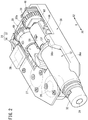
- the chemical solution administration device 10 includes the chemical solution container 12 filled with the chemical solution M, a gasket 22 slidably arranged in the chemical solution container 12, a plunger assembly 14A that is extendable in an axial direction (direction of the arrow X) and is capable of pressing the gasket 22 in the distal direction (direction of the arrow X1), a drive mechanism 24 that drives the plunger assembly 14A, batteries 26 that supply electric power necessary for an operation of the chemical solution administration device 10, a control unit 28 that controls the drive mechanism 24, a chassis structure 30 that supports the chemical solution container 12, the plunger assembly 14A, and the drive mechanism 24, and a casing 31 that accommodates these components.
- the chemical solution container 12 is formed in a hollow cylindrical shape having a chemical solution chamber 13 therein.
- the chemical solution container 12 includes a body portion 12a having a constant inner diameter and outer diameter in the axial direction, a shoulder portion 12b reduced in diameter from the distal end of the body portion 12a, and the distal end portion 12c protruding from the shoulder portion 12b in the distal direction.
- a proximal-end opening 12d is formed at the proximal end of the body portion 12a.
- a discharge port 12e communicating with the chemical solution chamber 13 is formed at the distal end portion 12c.
- the chemical solution M is filled in the chemical solution container 12 in advance.
- the chemical solution container 12 is preferably made of a transparent material.
- the discharge port 12e is sealed by a sealing member 29 made of an elastic resin material such as a rubber material or an elastomer material in a liquid-tight manner.
- a sealing member 29 made of an elastic resin material such as a rubber material or an elastomer material in a liquid-tight manner.
- the sealing member 29 is punctured by a needle 18a provided on the connector 18.
- the sealing member 29 is fixed to the distal end portion 12c of the chemical solution container 12 by a fixing cap 32 having an opening at the distal end. The distal end surface of the sealing member 29 is exposed from the opening of the fixing cap 32.
- the gasket 22 closes the proximal end side of the chemical solution chamber 13 in a liquid-tight manner.
- the gasket 22 is located on the distal end side with respect to the proximal end of the chemical solution container 12.
- the gasket 22 includes a gasket main body 34 and an abutment member 35 mounted to a proximal end of the gasket main body 34.
- the gasket main body 34 is made of a first material having elasticity.
- the first material is an elastic resin material such as a rubber material or an elastomer material.
- the outer peripheral portion of the gasket main body 34 is in close contact with the inner peripheral surface of the chemical solution container 12 (body portion 12a) in a liquid-tight manner.
- the gasket main body 34 includes a base portion 34a whose outer peripheral surface is in close contact with the body portion 12a of the chemical solution container 12 in a liquid-tight manner, and a conical portion 34b that protrudes from the base portion 34a in the distal direction and is reduced in diameter so as to be tapered in the distal direction.
- the abutment member 35 is made of a second material harder than the first material.
- the abutment member 35 includes a pressed portion 35a pressed by a gasket pressing portion 71 described later of the plunger assembly 14A. Further, the abutment member 35 includes an insertion portion 35b inserted into the gasket main body 34, and a proximal-end flange portion 35c provided at the proximal end of the insertion portion 35b.
- a male thread 35d provided on an outer peripheral portion of the insertion portion 35b is threadedly engaged with a female thread 34c provided on an inner peripheral portion of the gasket main body 34.
- the proximal-end flange portion 35c includes the pressed portion 35a on the proximal end surface.
- the pressed portion 35a is a plurality of convex portions 35a1 provided intermittently on the proximal end surface of the proximal-end flange portion 35c and protruding from the proximal end surface in the proximal direction (direction of the arrow X2).
- the convex portions 35a1 have a dome shape that bulges toward the proximal end.
- the plunger assembly 14A is configured to be extendable in the axial direction under the driving action of the drive mechanism 24, to cause the gasket 22 to move forward in the chemical solution container 12 with the extension, and to push out the chemical solution M from the chemical solution container 12.
- the distal end side of the plunger assembly 14A is inserted into the proximal end side of the chemical solution container 12. The details of the plunger assembly 14A will be described later.
- the drive mechanism 24 includes a motor 36 that is driven and controlled under the control of the control unit 28 using the batteries 26 as a power source, and a drive gear 37 fixed to an output shaft of the motor 36.
- the chassis structure 30 is arranged in the casing 31.
- the chemical solution container 12, the drive mechanism 24, and the plunger assembly 14A are fixed to predetermined positions of the chassis structure 30, respectively.
- the chassis structure 30 includes a chassis main-body member 38, a support member 39 that is fixed to the chassis main-body member 38 and rotatably supports a feed screw 48 of the plunger assembly 14A, and a motor holding member 40 that is fixed to the chassis main-body member 38 and holds the motor 36 between itself and the chassis main-body member 38.
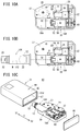
- the chassis main-body member 38 includes a base plate portion 38a (see also Fig. 10A ) constituting a bottom wall portion, and a flange mounting portion 38b that protrudes from the upper surface of the base plate portion 38a in the thickness direction (upward) of the base plate portion 38a and to which a flange portion 12f of the chemical solution container 12 is mounted.
- An electric board 27 to which the control unit 28 and the batteries 26 are attached is fixed to the chassis main-body member 38.
- the casing 31 is a hollow member configured to accommodate the chemical solution container 12, the gasket 22, the plunger assembly 14A, the drive mechanism 24, the batteries 26, the control unit 28, and the chassis structure 30 which are described above.
- the distal end portion 12c of the chemical solution container 12 protrudes from the casing 31 and is exposed to the outside.
- the casing 31 includes an upper surface 31a and a bottom surface 31b.
- a window portion 31w made of a transparent material is provided on the upper surface 31a of the casing 31, and the amount of liquid remaining in the chemical solution container 12 can be checked through the window portion 31w.
- the chemical solution administration device 10 may be configured as a patch type that is used by being applied to the skin S of a patient, for example.
- a sheet-shaped sticking portion (adhesive portion) that is capable of being stuck to the skin S is provided on the bottom surface 31b of the casing 31.
- a peelable protection sheet is applied to the sticking surface of the sticking portion.
- the chemical solution administration device 10 may be configured as a type in which a mounting tool such as a hook or a clip is provided on the bottom surface 31b of the casing 31, and it is attached to patient's clothes (for example, a waist portion of pants or the like) by hooking it.
- a mounting tool such as a hook or a clip
- the casing 31 has a first opening 31c into which the chemical solution container 12 is inserted.
- the distal end portion of the chemical solution container 12 protrudes from the casing 31 through the first opening 31c.
- a ring-shaped waterproof packing 42 is arranged between the vicinity of the distal end portion of the chemical solution container 12 and the casing 31.
- the waterproof packing 42 has an X-shaped cross-sectional shape, and is arranged in the first opening 31c.
- the outer peripheral portion of the waterproof packing 42 is in close contact with the inner surface of the first opening 31c over the entire circumference in a liquid-tight manner, and the inner peripheral portion of the waterproof packing 42 is in close contact with the outer peripheral surface of the chemical solution container 12 (body portion 12a) over the entire circumference in a liquid-tight manner.
- the waterproof packing 42 may have an O-shaped cross-sectional shape.
- the casing 31 includes a casing main-body portion 44 including an accommodating portion 45 that accommodates the chemical solution container 12 and a second opening 31d provided in the accommodating portion 45, a lid 46 that seals the second opening 31d, and an annular waterproof member 47 attached to the rim of the second opening 31d and in close contact with the lid 46.
- the first opening 31c ( Fig. 4 ) described above is provided in the casing main-body portion 44.
- the second opening 31d is provided at an end portion of the casing main-body portion 44 opposite to the side on which the first opening 31c is provided.
- the second opening 31d is formed larger than the chassis structure 30.
- the lid 46 is formed in a rectangular shape, and constitutes a wall portion of the casing 31 opposite to the side on which the distal end portion of the chemical solution container 12 protrudes.
- the waterproof member 47 is, for example, a waterproof tape, and is attached to a frame-shaped step 31e provided in the second opening 31d.
- the waterproof member 47 extends in a rectangular shape along the rectangular second opening 31d, and has a ring shape.
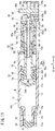
- the plunger assembly 14A includes the feed screw 48 driven by the drive mechanism 24, a first plunger 50 driven by the feed screw 48, a second plunger 52 driven by the feed screw 48, a nut member 54 held by the second plunger 52, and a base portion 56 that supports the second plunger 52.
- the feed screw 48 includes a rod portion 58 and a driven gear 60 coupled to the rod portion 58 and driven by the drive gear 37.
- the rod portion 58 includes a male thread portion 62 having a male thread 62a formed on the outer periphery, and an extending portion 63 extending from the proximal end of the male thread portion 62 in the proximal direction and not having the male thread formed on the outer periphery.
- the male thread portion 62 is longer than the extending portion 63.
- the distal end portion of the male thread portion 62 is located inside the chemical solution container 12.
- the outer diameter of the male thread portion 62 is larger than the outer diameter of the extending portion 63.
- the rod portion 58 further includes a coupling flange portion 64 provided at the proximal end of the extending portion 63.
- the coupling flange portion 64 includes a coupling concave portion 65a having a non-circular cross section on its proximal end surface, and is coupled (engaged) with a distal-end side shaft portion 60c of the driven gear 60 so as to be non-rotatable relatively.
- the driven gear 60 is rotatably arranged coaxially with the rod portion 58 and meshes with the drive gear 37 of the drive mechanism 24 (see Fig. 2 ).
- the driven gear 60 includes a gear portion 60b having a tooth portion 60a formed on an outer peripheral portion, the distal-end side shaft portion 60c protruding from the center of the distal end surface of the gear portion 60b in the distal direction, and a proximal-end side shaft portion 60d protruding from the center of the proximal end surface of the gear portion 60b in the proximal direction.
- the distal-end side shaft portion 60c and the proximal-end side shaft portion 60d are rotatably supported by the support member 39 of the chassis structure 30.
- a coupling convex portion 65b having a non-circular cross section inserted into the coupling concave portion 65a provided in the coupling flange portion 64 of the rod portion 58 is provided at the distal end of the distal-end side shaft portion 60c.
- a spring 66 that elastically urges the driven gear 60 in the distal direction is arranged between a support piece 39a of the support member 39 and the gear portion 60b.
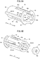
- the first plunger 50 includes a hollow first cylindrical body portion 68, an annular first distal-end flange 70 protruding radially outward from the distal end of the first cylindrical body portion 68, first protrusion portions 72 protruding radially outward from a proximal-end outer peripheral surface of the first cylindrical body portion 68, and support protrusions 74 protruding radially outward from the proximal-end outer peripheral surface of the first cylindrical body portion 68 at a circumferential position different from the first protrusion portions 72.
- a first female thread portion 68a threadedly engaged with the male thread portion 62 of the first plunger 50 at least in an initial state before the plunger assembly 14A starts the extension operation.
- the first distal-end flange 70 is a flange portion that is capable of being held in abutment against the inner peripheral surface of the chemical solution container 12.
- the distal end surface of the first distal-end flange 70 is a gasket pressing portion 71 that is capable of pressing the gasket 22. In the initial state of the chemical solution administration device 10, the gasket pressing portion 71 is separated from the gasket 22 by a small distance.
- the first protrusion portions 72 each constitute a first guided portion 73 guided by a first guide portion 86 ( Fig. 7A ) described later of the second plunger 52.
- the distal end surface of each of the first protrusion portions 72 constitutes a first engagement portion 75 that is engageable with a second engagement portion 98 ( Fig. 7A ) described later of the second plunger 52.
- the proximal end surface of each of the first protrusion portions 72 constitutes a first abutment portion 76 that is capable of being held in abutment against a second abutment portion 53 ( Fig. 7B ) described later of the second plunger 52.
- the support protrusions 74 support temporary locking claw portions 85a ( Fig. 7A ) described later of the second plunger 52 from inside.
- the second plunger 52 includes a plunger main-body portion 78 and a cap member 80 fixed to the plunger main-body portion 78.
- the plunger main-body portion 78 includes a hollow second cylindrical body portion 82, a pair of second distal-end flanges 83 protruding radially outward from the distal end of the second cylindrical body portion 82, and second protrusion portions 84 protruding radially outward from the outer surface of the second cylindrical body portion 82 and extending in the axial direction.
- the second cylindrical body portion 82 is provided with temporary locking elastic pieces 85 that is elastically deformable in the radial direction. An end portion (free end portion) of each of the temporary locking elastic pieces 85 is provided with the temporary locking claw portion 85a protruding outward.
- the second cylindrical body portion 82 is provided with the first guide portions 86.
- the first guide portions 86 are each engaged with the first guided portion 73 of the first plunger 50, prevent the rotation of the first plunger 50 with respect to the second plunger 52, and guide movement of the first plunger 50 in the axial direction.
- the second distal-end flanges 83 extend in an arc shape. A notch-shaped gap is formed between the pair of second distal-end flanges 83.
- the first guide portions 86 each include an axial guide 86a that extends along the axial direction and guide the first guided portion 73 ( Fig. 6 ) of the first plunger 50 in the axial direction, and a rotation guide 86b that is continuous with the distal end of the axial guide 86a and extends in the circumferential direction to guide the first guided portion 73 in the circumferential direction.
- the rotation guides 86b each include a first end portion 86b1 continuous with the axial guide 86a, and a second end portion 86b2 different from the first end portion 86b1.
- the first guide portions 86 each further include a lock portion 86c that is continuous with the second end portion 86b2 of the rotation guide 86b.
- the lock portions 86c each extend from the second end portion 86b2 in the proximal direction with a length shorter than the axial guide 86a, and are each capable of locking the first guided portion 73 of the first plunger 50.
- the axial guides 86a are hole portions penetrating the peripheral wall portion of the second cylindrical body portion 82 in the wall thickness direction, and the two axial guides 86a are provided at positions opposite to each other with the axis of the second cylindrical body portion 82 as a reference.
- the two rotation guides 86b are provided at positions opposite to each other with the axis of the second cylindrical body portion 82 as a reference.
- the lock portions 86c are hole portions penetrating the peripheral wall portion of the second cylindrical body portion 82 in the wall thickness direction, and the two lock portions 86c are provided at positions opposite to each other with the axis of the second cylindrical body portion 82 as a reference.
- the proximal end surface of each of the lock portions 86c constitutes the second abutment portion 53 that is capable of being held in abutment against the first abutment portion 76 ( Fig. 6 ) of the first plunger 50.
- a nut accommodating portion 88 is provided at a proximal end portion of the second cylindrical body portion 82.
- the nut accommodating portion 88 accommodates the nut member 54 so that the nut member 54 is non-rotatable and movable in the axial direction.
- the inner peripheral shape of the nut accommodating portion 88 is formed in a hexagonal shape in accordance with the outer diameter of the nut member 54.
- a plurality of ribs 88b extending along the axial direction and arranged at intervals in the circumferential direction are formed on an inner peripheral surface 88a of the nut accommodating portion 88, and the plurality of ribs 88b are held in abutment against the outer peripheral surface of the nut member 54.
- the nut accommodating portion 88 includes a distal-end pedestal portion 89 and a proximal-end pedestal portion 90.
- the distal-end pedestal portion 89 is a proximal end surface of an inner peripheral protruding wall 82a (see also Fig. 7B ) having a hole portion, which is provided inside the second cylindrical body portion 82.
- the proximal-end pedestal portion 90 is a distal end surface of a pedestal member 82b fixed inside the proximal end of the second cylindrical body portion 82.
- a nut urging member 92 that urges the nut member 54 in the distal direction is arranged in the nut accommodating portion 88.
- the nut urging member 92 is a coil spring.
- the rod portion 58 of the feed screw 48 is inserted into the nut urging member 92.
- the distal end surface of the nut member 54 is held in abutment against the distal-end pedestal portion 89, the distal end of the nut urging member 92 is held in abutment against the proximal end surface of the nut member 54, and the proximal end of the nut urging member 92 is held in abutment against the proximal-end pedestal portion 90.
- the second protrusion portions 84 each constitute a second guided portion 94 guided by a second guide portion 100 ( Fig. 9 ) described later of the base portion 56.
- the second protrusion portions 84 each extend in the axial direction over substantially the overall length of the second cylindrical body portion 82, and are each provided between the axial guide 86a and the lock portion 86c of the first guide portion 86.
- the distal end of each of the second protrusion portions 84 is continuous with the second distal-end flange 83.
- the two second protrusion portions 84 are provided at positions opposite to each other with the axis of the second cylindrical body portion 82 as a reference.
- the cap member 80 is fixed to the distal end of the plunger main-body portion 78.
- the cap member 80 includes a distal-end ring portion 96 having an opening 96a, and a pair of coupling arms 97 protruding in the proximal direction from the outer rim of the proximal end surface of the distal-end ring portion 96.
- the first cylindrical body portion 68 ( Fig. 6 ) of the first plunger 50 is inserted into the opening 96a of the distal-end ring portion 96.
- the outer peripheral portion of the distal-end ring portion 96 is a distal-end outer peripheral portion that is capable of being held in abutment against the inner peripheral surface of the chemical solution container 12.
- the proximal end surface of the distal-end ring portion 96 includes second engagement portions 98 that is engageable with the first engagement portions 75 of the first plunger 50.
- each of the coupling arms 97 is provided with an engagement claw 97a protruding inward.
- the engagement of the engagement claws 97a with distal ends of slits 85b formed on both sides of the temporary locking elastic pieces 85 prevents the cap member 80 from being disengaged from the plunger main-body portion 78.
- a second female thread portion 54a that is capable of being threadedly engaged with the male thread portion 62 of the feed screw 48 is formed on the inner periphery, and the feed screw 48 is inserted therein.
- the extending portion 63 of the feed screw 48 is inserted into the nut member 54 in an initial state.
- the nut member 54 has a hexagonal outer shape. Note that the nut member 54 may have a non-circular outer shape such as another polygonal shape.
- the base portion 56 is fixed to the chassis structure 30.
- the base portion 56 is a hollow member, and includes the groove-shaped second guide portions 100 extending in the axial direction.
- the two second guide portions 100 are provided at positions opposite to each other with the axis of the base portion 56 as a reference.
- the second guide portions 100 are each engaged with a second guided portion 94 ( Fig. 7A or the like) of the second plunger 52, prevent the rotation of the second plunger 52 with respect to the feed screw 48, and guide axial movement of the second plunger 52.
- the base portion 56 includes temporary locking concave portions 102 into which the temporary locking claw portions 85a ( Fig. 7A or the like) of the second plunger 52 are disengageably inserted.
- the temporary locking concave portions 102 have a form of a hole penetrating the peripheral wall portion of the base portion 56 in the thickness direction.
- the temporary locking concave portions 102 may be grooves provided on the inner peripheral surface of the base portion 56. Notches 56a into which the coupling arms 97 ( Fig. 7A ) of the cap member 80 are inserted are provided at the distal end of the base portion 56.
- the chemical solution administration device 10 configured as described above is assembled, for example, by the following procedure.
- the plunger assembly 14A, the drive mechanism 24, and the electric board 27 to which the control unit 28 and the batteries 26 are attached are assembled (fixed) at predetermined positions of the chassis structure 30.
- a prefilled syringe 104 is assembled to the chassis structure 30.
- the prefilled syringe 104 is an assembly in which the sealing member 29 and the fixing cap 32 are mounted to the distal end portion of the chemical solution container 12, the chemical solution M is filled in the chemical solution container 12, and the gasket 22 is inserted into the chemical solution container 12.
- the chassis structure 30 to which the plunger assembly 14A and the like are assembled is inserted into the casing main-body portion 44 through the second opening 31d of the casing main-body portion 44.
- the chemical solution container 12 is inserted into the waterproof packing 42 ( Fig. 4 ) arranged in the first opening 31c of the casing main-body portion 44, and the waterproof packing 42 is in close contact with the outer peripheral surface of the chemical solution container 12 in a liquid-tight manner.
- the second opening 31d of the casing main-body portion 44 is closed with the lid 46.
- the lid 46 is in close contact with the waterproof member 47 arranged in the second opening 31d of the casing main-body portion 44 in a liquid-tight manner.
- a waterproof structure is constructed.
- the second plunger 52 does not move forward even when the feed screw 48 rotates.
- the first plunger 50 rotates by a predetermined angle in accordance with the rotation of the feed screw 48.
- the first guided portions 73 of the first plunger 50 reach the rotation guides 86b provided at the distal ends of the first guide portions 86 of the second plunger 52 (are disengaged from the axial guides 86a)
- the first plunger 50 is rotatable with respect to the second plunger 52.
- the first plunger 50 in which the first guided portions 73 have reached the rotation guides 86b moves so as to follow the feed screw 48 only while the first guided portions 73 move from the first end portions 86b1 to the second end portions 86b2 of the rotation guides 86b.
- the first plunger 50 causes the second plunger 52 to move forward. That is, with the rotation of the feed screw 48, the first plunger 50 moves forward while pulling the second plunger 52. At this time, the temporary locking claw portions 85a of the second plunger 52 come off the temporary locking concave portions 102 of the base portion 56. With the forward movement of the second plunger 52, the male thread portion 62 of the feed screw 48 is threadedly engaged with the nut member 54 arranged on the second plunger 52.
- the second plunger 52 starts to move forward, as illustrated in Fig. 15A , the proximal end of the male thread portion 62 comes into contact with the distal end of the second female thread portion 54a of the nut member 54. Even when the second female thread portion 54a does not mesh with the male thread portion 62 at the same time as this contact, since the nut member 54 is slidable relatively in the axial direction within the nut accommodating portion 88, as illustrated in Fig. 15B , the second plunger 52 can move forward by following the first plunger 50. At this time, the nut member 54 moves in the proximal direction relative to the second plunger 52 moving forward, against the urging force of the nut urging member 92.
- the nut member 54 which has been brought into a rotation-restricted state by the nut accommodating portion 88, moves forward with the rotation of the feed screw 48 while maintaining the distance from the distal-end pedestal portion 89 (moves forward at the same speed as the second plunger 52).
- the nut member 54 moves forward with the rotation of the feed screw 48, and comes into abutment against the distal-end pedestal portion 89 of the second plunger 52. Therefore, when the nut member 54 moving forward presses the distal-end pedestal portion 89 in the distal direction, the second plunger 52 starts to move forward. At this time, since the first plunger 50, which has been released from the thread engagement with the feed screw 48, is stopped, with the forward movement of the second plunger 52, as illustrated in Fig. 18 , the second abutment portion 53 of the second plunger 52 comes into abutment against the first abutment portion 76 of the first plunger 50.
- the second abutment portion 53 of the second plunger 52 moving forward presses the first abutment portion 76 in the distal direction, whereby the first plunger 50 starts to move forward again. Accordingly, the first plunger 50 and the second plunger 52 move forward in a state where only the nut member 54 is threadedly engaged with the feed screw 48, and liquid is fed.
- the chemical solution administration device 10 including the plunger assembly 14A according to the present embodiment has the following effects.
- the plunger assembly 14A includes the feed screw 48 including the male thread portion 62 and the extending portion 63, the first plunger 50 including the first female thread portion 68a, the second plunger 52 including the second female thread portion 54a, the nut member 54 that is assumingly movable in the axial direction with respect to the second plunger 52, and the base portion 56. After that, with the rotation of the feed screw 48, first, the first plunger 50 moves forward, and then the first plunger 50 moves forward while pulling the second plunger 52. Thereafter, the nut member 54 threadedly engaged with the feed screw 48, and then the second plunger 52 causes the first plunger 50 to move forward.
- the plunger assembly 14A configured as described above extends in a plurality of stages, so that the overall length can be shortened, and accordingly, the medicinal solution administration device 10 to which the plunger assembly 14A is mounted can be downsized.
- the downsizing of the device makes it possible to reduce the area required for application when the device is applied to a patient's body surface, so that the device can be easily applied to applications such as application to the patient's body surface.
- the downsizing of the device can improve usability such as carrying and storing.
- the nut member 54 is movable in the axial direction relative to the second plunger 52, even when the male thread portion 62 of the feed screw 48 and the second female thread portion 54a of the nut member 54 do not mesh with each other at the same time as the contact between the male thread portion 62 of the feed screw 48 and the nut member 54, these can be threadedly engaged with each other when the phase of the male thread portion 62 and the phase of the second female thread portion 54a match with each other thereafter. Therefore, the second plunger 52 can be reliably caused to move forward through the nut member 54 by the feed screw 48.
- the plunger assembly 14A includes the nut urging member 92 that urges the nut member 54 in the distal direction, and in the initial state, the distal end surface of the nut member 54 is held in abutment against the distal-end pedestal portion 89, the distal end of the nut urging member 92 is held in abutment against the proximal end surface of the nut member 54, and the proximal end of the nut urging member 92 is held in abutment against the proximal-end pedestal portion 90.
- the feed screw 48 and the nut member 54 can be threadedly engaged with each other reliably. That is, while the second plunger 52 moves forward by the pitch of the male thread portion 62, the feed screw 48 and the nut member 54 are always threadedly engaged with each other.
- the nut urging member 92 may not be provided. In this case, even if the meshing between the male thread portion 62 and the second female thread portion 54a fails several times while the second plunger 52 moves forward, the meshing is achieved somewhere within the movable range of the nut member 54. Therefore, the second plunger 52 can be caused to move forward by the rotation of the feed screw 48.
- the plurality of ribs 88b extending along the axial direction and arranged at intervals in the circumferential direction are formed on the inner peripheral surface of the nut accommodating portion 88, and the plurality of ribs 88b are held in abutment against the outer peripheral surface of the nut member 54.
- the distal end of the first plunger 50 includes the flange portion that is capable of being held in abutment against the inner peripheral surface of the chemical solution container 12. With this configuration, buckling of the first plunger 50 can be prevented.
- the second plunger 52 includes the plunger main-body portion 78 including the nut accommodating portion 88, the first guide portions 86, the second guided portions 94, and the second abutment portions 53, and the cap member 80 fixed to the plunger main-body portion 78 and including the second engagement portions 98.
- the second plunger 52 including the first guide portions 86, the second guided portions 94, the second abutment portions 53, and the second engagement portions 98 can be easily manufactured by injection molding.
- the cap member 80 has a distal-end outer peripheral portion that is capable of being held in abutment against the inner peripheral surface of the chemical solution container 12. With this configuration, buckling of the second plunger 52 can be prevented.
- the first guide portions 86 of the second plunger 52 each include the axial guide 86a that guides the first guided portion 73 of the first plunger 50 in the axial direction, and the rotation guide 86b that is continuous with the distal end of the axial guide 86a and guides the first guided portion 73 in the circumferential direction ( Fig. 7B ). With this configuration, the first plunger 50 can be rotated with the rotation of the feed screw 48 at the distal ends of the first guide portions 86.
- the first guide portions 86 of the second plunger 52 each include the lock portion 86c that is continuous with the second end portion 86b2 of the rotation guide 86b ( Fig. 7B ). With this configuration, the first guided portions 73 are prevented from returning to the axial guides 86a of the first guide portions 86.
- the second plunger 52 includes the temporary locking elastic pieces 85 each including the temporary locking claw portion 85a provided at the end portion thereof, and the base portion 56 includes the temporary locking concave portions 102 into which the temporary locking claw portions 85a are disengageably inserted.
- the first plunger 50 includes the support protrusions 74 that each support the temporary locking claw portion 85a from inside. With this configuration, it is possible to prevent the temporary locking claw portions 85a from being disengaged from the temporary locking concave portions 102 until the first plunger 50 moves forward to some extent.
- the casing 31 has the first opening 31c into which the chemical solution container 12 is inserted. ( Fig. 4 ).
- the chemical solution container 12 has the distal end portion protruding from the casing 31 through the first opening 31c, and the ring-shaped waterproof packing 42 is arranged between the vicinity of the distal end portion of the chemical solution container 12 and the casing 31. With this configuration, it is possible to prevent water from entering the casing 31 through the first opening 31c.
- the casing 31 includes the casing main-body portion 44 including the accommodating portion 45 and the second opening 31d, the lid 46 that seals the second opening 31d, and the annular waterproof member 47 attached to the second opening 31d ( Fig. 5 ). With this configuration, it is possible to prevent water from entering the casing 31 through the second opening 31d.
- the chemical solution administration device 10 includes the chassis structure 30 in which the chemical solution container 12, the drive mechanism 24, and the plunger assembly 14A are fixed at predetermined positions, respectively. Then, the chassis structure 30 is arranged in the casing 31, and the second opening 31d is formed to be larger than the chassis structure 30. With this configuration, the plunger assembly 14A and the like can be easily taken out of the casing 31 together with the chassis structure 30 through the second opening 31d.
- the first plunger 50 is rotatable by a predetermined angle with respect to the second plunger 52 with the rotation of the feed screw 48 at the distal end of the first guide portion 86 of the second plunger 52 ( Fig. 13A and Fig. 13B ).
- the gasket 22 includes the gasket main body 34 made of the first material having elasticity, and the abutment member 35 made of the second material harder than the first material and mounted to the proximal end of the gasket main body 34 ( Fig. 3 ).
- the abutment member 35 includes the pressed portion 35a pressed by the gasket pressing portion 71.
- the gasket pressing portion 71 is made of a material harder than the first material. With this configuration, the sliding resistance of the first plunger 50 in the rotation direction with respect to the gasket 22 can be reduced. Therefore, the gasket 22 does not hinder the rotation of the first plunger 50.
- the abutment member 35 includes the insertion portion 35b inserted into the gasket main body 34, and the proximal-end flange portion 35c provided at the proximal end of the insertion portion 35b.
- the proximal-end flange portion 35c includes the pressed portion 35a on the proximal end surface.
- the pressed portion 35a is a plurality of convex portions provided intermittently on the proximal end surface and protruding from the proximal end surface in the proximal direction.
- the convex portions have a dome shape that bulges toward the proximal end. With this configuration, the sliding resistance of the first plunger 50 in the rotation direction with respect to the gasket 22 can be more effectively reduced.
- the first plunger 50 moves forward in the axial direction ( Fig. 11 ), the first engagement portions 75 of the first plunger 50 are engaged with the second engagement portions 98 of the second plunger 52, and the first plunger 50 moving forward causes the second plunger 52 to move forward ( Fig. 14 ).
- the nut member 54 moves in the proximal direction relative to the second plunger 52 ( Fig.15B ), and the movement of the nut member 54 causes the nut member 54 to be threadedly engaged with the male thread portion 62 of the feed screw 48 ( Fig. 16 ).
- the nut member 54 threadedly engaged with the male thread portion 62 moves forward with the rotation of the feed screw 48 to cause the second plunger 52 to move forward, and the second plunger 52 moving forward causes the first plunger 50 to move forward ( Fig. 16 ).
- the male thread portion 62 of the feed screw 48 and the second female thread portion 54a of the nut member 54 can be threadedly engaged with each other smoothly. Therefore, the second plunger 52 can be reliably caused to move forward through the nut member 54 by the feed screw 48.
- the nut member 54 is urged in the distal direction by the nut urging member 92.
- the second female thread portion 54a of the nut member 54 is threadedly engaged with the male thread portion 62 of the feed screw 48 (see Fig. 15B and Fig. 16 ).
- the feed screw 48 and the nut member 54 can be threadedly engaged with each other reliably.
- the first plunger 50 restricted in rotation with respect to the feed screw 48 moves to the vicinity of the distal end of the second plunger 52 ( Fig. 12 ), and the first plunger 50 that has moved to the vicinity of the distal end of the second plunger 52 rotates by a predetermined angle in accordance with the rotation of the feed screw 48 ( Fig. 13A and Fig. 13B ). Further, the first plunger 50 that has rotated by the predetermined angle is restricted in rotation again, and the first engagement portions 75 of the first plunger 50 are engaged with the second engagement portions 98 of the second plunger 52. Then, the first plunger 50 in which the first engagement portions 75 are engaged with the second engagement portions 98 moves forward while pulling the second plunger 52 ( Fig. 14 ). Accordingly, the second plunger 52 can be caused to move forward by the first plunger 50 moving forward with the rotation of the feed screw 48.
- the feed screw 48 rotates, and the first plunger 50 and the second plunger 52 move forward ( Fig. 16 ). Further, after the second plunger 52 moves forward by a predetermined length, the first female thread portion 68a of the first plunger 50 is disengaged from the male thread portion 62 ( Fig. 17 ).
- the second plunger 52 causes the first plunger 50 to move forward in a state where the first female thread portion 68a is disengaged from the male thread portion 62 and the second female thread portion 54a is threadedly engaged with the male thread portion 62.
- the transition from the double screw state in which the male thread portion 62 of the feed screw 48 is threadedly engaged with both the first female thread portion 68a and the second female thread portion 54a to the state in which only the second female thread portion 54a and the male thread portion 62 are threadedly engaged with each other is performed smoothly, and the first plunger 50 can be caused to move forward by the second plunger 52.
- a plunger assembly 14B illustrated in Fig. 20 to Fig. 31 may be employed instead of the plunger assembly 14A.
- the same or similar components as those of the plunger assembly 14A are denoted by the same reference numerals, and detailed description thereof will be omitted.
- the plunger assembly 14B includes a feed screw 108 driven by the drive mechanism 24 ( Fig. 2 ), a first plunger 110 driven in the distal direction by the feed screw 108, a second plunger 112 driven in the distal direction by the feed screw 108, the nut member 54 held by the second plunger 112, a base portion 114 that supports the second plunger 112, and a support mechanism 116 arranged inside the first plunger 110.
- the feed screw 108 includes a rod portion 118 and a driven gear 120 coupled to the rod portion 118 and driven by the drive gear 37 ( Fig. 2 ).
- the rod portion 118 includes the male thread portion 62 having the male thread 62a formed thereon, and the extending portion 63 extending from the proximal end of the male thread portion 62 in the proximal direction and not having the male thread formed thereon.
- the driven gear 120 is fixed to the proximal end of the extending portion 63 of the rod portion 118 so as to be non-rotatable relatively, and meshes with the drive gear 37 ( Fig. 2 ) of the drive mechanism 24.
- the first plunger 110 includes a hollow first plunger main body 122 supported by the second plunger 112, a gasket pressing portion 124 fixed to the distal end of the first plunger main body 122, and a nut member 126 (hereinafter, referred to as "first nut member 126") fixed to the proximal end of the first plunger main body 122.
- a peripheral wall portion 123 of the first plunger main body 122 has a non-circular outer contour shape in a cross section perpendicular to the axial direction.
- the peripheral wall portion 123 of the first plunger 110 includes a pair of flat wall portions 123a facing each other and a pair of arc-shaped wall portions 123b facing each other.
- the outer surface of the peripheral wall portion 123 of the first plunger 110 constitutes a first guided portion 127 guided by a first guide portion 142 described later of the second plunger 112.
- the first plunger main body 122 is provided with engagement elastic pieces 122a that is elastically deformable inward and outward of the first plunger main body 122.
- the two engagement elastic pieces 122a are provided on sides opposite to each other with the axis of the first plunger main body 122 as a reference.
- an outwardly protruding engagement claw portion 122b is provided at the proximal end (free end portion) of each of the engagement elastic pieces 122a.
- the distal end surface of each of the engagement claw portions 122b constitutes a first engagement portion 128 that is engageable with a second engagement portion 150 described later of the second plunger 112.
- the proximal end surface of each of the engagement claw portions 122b constitutes a first abutment portion 130 that is capable of being held in abutment against a second abutment portion 152 described later of the second plunger 112.
- the gasket pressing portion 124 includes an insertion portion 124a inserted into the gasket 131, a proximal-end flange portion 124b protruding radially outward from a proximal end of the insertion portion 124a, and a hollow central cylindrical portion 124c protruding from the center of a distal-end wall portion of the insertion portion 124a in the proximal direction.
- the proximal-end flange portion 124b faces the proximal end surface of the gasket 131 and can be held in abutment against the inner peripheral surface of the chemical solution container 12.
- the central cylindrical portion 124c protrudes in the proximal direction with respect to the proximal-end flange portion 124b.
- the male thread portion 62 of the feed screw 108 is inserted into the central cylindrical portion 124c.
- the first nut member 126 is held (fixed) so as to be non-rotatable with respect to the first plunger main body 122 by a nut holding portion 132 provided inside the proximal end of the first plunger main body 122.
- the first female thread portion 68a is formed on an inner peripheral portion of the first nut member 126. Note that the first nut member 126 may be eliminated, and the first female thread portion 68a may be formed directly on the first plunger main body 122.
- the second plunger 112 includes a cylindrical body portion 134, a distal-end flange portion 136 protruding outward from a distal end of the cylindrical body portion 134, temporary locking claw portions 138 provided to an outer surface of the cylindrical body portion 134, and a nut accommodating portion 140 provided inside the proximal end of the cylindrical body portion 134.
- the two temporary locking claw portions 138 are provided on sides opposite to each other with the axis of the second plunger 112 as a reference.
- the temporary locking claw portions 138 each have an inclined surface that is inclined inward in the distal direction.
- the nut member 54 (hereinafter, referred to as "second nut member 54") is accommodated in the nut accommodating portion 140 so as to be movable relatively in the axial direction. Note that, similarly to the plunger assembly 14A described above, the nut urging member 92 and the pedestal member 82b ( Fig. 3 and the like) may be arranged in the nut accommodating portion 140.
- the cylindrical body portion 134 of the second plunger 112 has a non-circular outer contour shape in a cross section perpendicular to the axial direction.
- the cylindrical body portion 134 includes a pair of flat wall portions 134a facing each other and a pair of arc-shaped wall portions 134b facing each other.
- the inner surface of the cylindrical body portion 134 constitutes the first guide portion 142 that prevents the rotation of the first plunger 110 with respect to the second plunger 112 and guides the axial movement of the first plunger 110.
- the outer surface of the cylindrical body portion 134 constitutes a second guided portion 144 guided by a second guide portion 164 described later of the base portion 114.
- distal-end concave portions 146 are provided at the distal end of the cylindrical body portion 134 of the second plunger 112, and proximal-end concave portions 148 are provided at the proximal end of the cylindrical body portion 134.
- the distal-end concave portions 146 and the proximal-end concave portions 148 each penetrate the peripheral wall of the cylindrical body portion 134 in the thickness direction.
- the distal end surface of each of the distal-end concave portions 146 constitutes the second engagement portion 150 that is engageable with the first engagement portion 128 of the first plunger 110.
- the second engagement portion 150 is inclined inward in the proximal direction.
- the proximal end surface of each of the distal-end concave portions 146 constitutes the second abutment portion 152 that is capable of being held in abutment against the first abutment portion 130 of the first plunger 110.
- the second abutment portion 152 is inclined inward in the distal direction.
- the distal end surface of each of the proximal-end concave portions 148 is inclined inward in the distal direction.
- the base portion 114 is a hollow member, and is fitted into the proximal-end opening 12d of the chemical solution container 12.
- the base portion 114 includes a base-portion body 154, a fitting protrusion 156 protruding outward from a distal end of the base-portion body 154, a proximal-end flange 158 protruding outward from a proximal end of the base-portion body 154, and temporary locking protrusions 160 protruding inward from the proximal end of the base-portion body 154.
- the distal end surface of the proximal-end flange 158 is held in abutment against the proximal end surface of the chemical solution container 12.
- the temporary locking claw portions 138 of the second plunger 112 are releasably engaged with the temporary locking protrusions 160.
- the base-portion body 154 has a non-circular shape along the outer shape of the second plunger 112 in a cross section perpendicular to the axial direction.
- the inner surface of the base-portion body 154 constitutes the second guide portion 164.
- the second guide portion 164 is engaged with the second guided portion 144 which is the inner surface of the second plunger 112, prevents rotation of the second plunger 112 with respect to the base portion 114, and guides axial movement of the second plunger 112.
- the support mechanism 116 includes a support member 166 arranged in the first plunger main body 122 so as to be non-rotatable relative to the first plunger main body 122 and movable in the axial direction relative to the first plunger main body 122, a third nut member 168 held by the support member 166, and an urging member 170 that elastically urges the support member 166 in the proximal direction.
- the support member 166 includes a pair of support arms 167 provided close to (or in contact with) the inner surface of the first plunger main body 122. As described later, the support arms 167 are capable of supporting the engagement elastic pieces 122a from inside.
- the third nut member 168 is held so as to be non-rotatable with respect to the support member 166.
- a third female thread portion 168a is formed on the inner peripheral portion of the third nut member 168. In the initial state of the plunger assembly 14B, the third female thread portion 168a is threadedly engaged with the male thread portion 62 of the feed screw 108.
- the urging member 170 is a coil spring arranged between the gasket pressing portion 124 of the first plunger 110 and the support member 166.
- the distal end of the urging member 170 is held in abutment against the distal-end wall portion of the insertion portion 124a of the gasket pressing portion 124.
- the proximal end of the urging member 170 is held in abutment against the support member 166.
- the central cylindrical portion 124c of the gasket pressing portion 124 is inserted into the urging member 170.
- the second plunger 112 since the temporary locking claw portions 138 of the second plunger 112 are inserted into the temporary locking protrusions 160 of the base portion 114 ( Fig. 21 ), and the male thread portion 62 of the feed screw 108 is not threadedly engaged with the nut member 54 (the extending portion 63 of the feed screw 108 is inserted into the nut member 54), the second plunger 112 does not move forward even when the feed screw 108 rotates. Further, as illustrated in Fig.
- the engagement claw portions 122b of the first plunger 110 are disengaged from the proximal-end concave portions 148 of the second plunger 112 by a hinge function (elastic deformation function) of the engagement elastic pieces 122a and is drawn into the second plunger 112.
- the engagement elastic pieces 122a of the first plunger 110 are displaced outward by its elastic restoring force, and the engagement claw portions 122b enter the distal-end concave portions 146 of the second plunger 112, so that the first engagement portions 128 (distal end surfaces of the engagement claw portions 122b) of the first plunger 110 are engaged with the second engagement portions 150 (distal end surfaces of the distal-end concave portions 146) of the second plunger 112.
- the first plunger 110 when the first plunger 110 moves forward with the first engagement portions 128 of the first plunger 110 and the second engagement portions 150 of the second plunger 112 engaged with each other, the first plunger 110 causes the second plunger 112 to move forward. That is, with the rotation of the feed screw 108, the first plunger 110 moves forward while pulling the second plunger 112. At this time, the temporary locking claw portions 138 ( Fig. 21 ) of the second plunger 112 climb over the temporary locking protrusions 160 ( Fig. 21 ) of the base portion 114, and enter the groove portions 162 ( Fig. 21 ) provided on the inner surface of the base portion 114.
- the support member 166 urged in the proximal direction by the urging member 170 is displaced in the proximal direction relative to the first plunger 110 (the position of the support member 166 is not changed from the time when the thread engagement between the third nut member 168 and the male thread portion 62 is released).
- the proximal end of the male thread portion 62 comes into contact with the distal end of the second female thread portion 54a of the nut member 54.
- the male thread portion 62 of the feed screw 108 is threadedly engaged with the second nut member 54 arranged on the second plunger 112.
- the second nut member 54 moves in the axial direction relative to the second plunger 112, thread engagement between the second nut member 54 and the male thread portion 62 is achieved.
- the first plunger 110 and the second plunger 112 move forward in the double screw state.
- the nut member 54 does not cause the second plunger 112 to move forward, but by the engagement between the first engagement portions 128 and the second engagement portions 150, the first plunger 110 causes the second plunger 112 to move forward.
- the first nut member 126 (first female thread portion 68a) of the first plunger 110 comes off the male thread portion 62 of the feed screw 108 (the thread engagement of the female thread portion 68a is released).
- the support member 166 is displaced relative to the first plunger 110 until reaching a position where the nut accommodating portion 140 of the first plunger 110 comes into abutment against the support member 166.
- the support arms 167 of the support member 166 are located inside the engagement elastic pieces 122a.
- the second nut member 54 threadedly engaged with the feed screw 108 causes the second plunger 112 to move forward, and the second plunger112 moving forward causes the first plunger 110 to move forward.
- the second nut member 54 moves forward with the rotation of the feed screw 108, and comes into abutment against the distal-end pedestal portion 89 of the second plunger 112. Therefore, when the nut member 54 moving forward presses the distal-end pedestal portion 89 in the distal direction, the second plunger 112 starts to move forward.
- the first plunger 110 and the second plunger 112 move forward in a state where only the second nut member 54 is threadedly engaged with the feed screw 108, and liquid is fed.
- the support arms 167 of the support member 166 support the engagement elastic pieces 122a of the first plunger 110 from inside, so that the engagement claw portions 122b provided on the engagement elastic pieces 122a are prevented from being disengaged from the distal-end concave portions 146.
- the same effects as those of the plunger assembly 14A can be obtained for components similar to those of the plunger assembly 14A.
Landscapes
- Health & Medical Sciences (AREA)
- Vascular Medicine (AREA)
- Engineering & Computer Science (AREA)
- Anesthesiology (AREA)
- Biomedical Technology (AREA)
- Heart & Thoracic Surgery (AREA)
- Hematology (AREA)
- Life Sciences & Earth Sciences (AREA)
- Animal Behavior & Ethology (AREA)
- General Health & Medical Sciences (AREA)
- Public Health (AREA)
- Veterinary Medicine (AREA)
- Infusion, Injection, And Reservoir Apparatuses (AREA)
Abstract
Description
- The present invention relates to a plunger assembly, a chemical solution administration device, and a driving method of the plunger assembly.
- Conventionally, a syringe pump type chemical solution administration device that administers a chemical solution filled in a cylinder into a living body under the pressing action of a plunger is known. Further, for example, as disclosed in
WO 2013/148270 A , in this type of chemical solution administration device, a mechanism that causes a plunger and a screw shaft to be threadedly engaged with each other, and the plunger is caused to move forward under the rotating action of the screw shaft (hereinafter, referred to as "plunger mechanism according to the prior art") is known. - By the way, in recent years, the chemical solution administration device has been downsized, and a type that is applied to a body has appeared. In particular, in the case of a chemical solution administration device of the type that is applied to a body, it is required to reduce the size of the chemical solution administration device as much as possible from the viewpoint of the limited area that can be applied and usability. In the plunger mechanism according to the prior art, the effect of reducing the size of the chemical solution administration device is not sufficient because only a single plunger moves forward with respect to the screw shaft.
- The present invention has been made in consideration of such a problem, and has an object to provide a plunger assembly, a chemical solution administration device, and a method of driving the plunger assembly, which can more effectively downsize the device.
- In order to achieve the above object, according to the present invention, there is provided a plunger assembly that is extendable in an axial direction, and with the extension, presses a gasket slidably arranged inside a chemical solution container to push out a chemical solution from the chemical solution container, the plunger assembly including: a feed screw including a rod portion, the rod portion including a male thread portion having a male thread formed thereon, and an extending portion extending from a proximal end of the male thread portion in a proximal direction and not having the male thread formed thereon; a first plunger including a gasket pressing portion that is capable of pressing the gasket, a first female thread portion threadedly engaged with the male thread portion of the feed screw at least in an initial state before the plunger assembly starts an extension operation, and a first guided portion, a first engagement portion, and a first abutment portion; a second plunger including a first guide portion, a second guided portion, a second engagement portion, a second abutment portion, and a nut accommodating portion; a nut member having a second female thread portion formed on an inner periphery thereof, and into which the feed screw is inserted; and a base portion on which a second guide portion is formed, in which the first guide portion of the second plunger is engaged with the first guided portion of the first plunger, prevents rotation of the first plunger with respect to the second plunger, and guides movement of the first plunger in the axial direction, in which the second guide portion of the base portion is engaged with the second guided portion, prevents rotation of the second plunger with respect to the base portion, and guides movement of the second plunger in the axial direction, in which the nut accommodating portion accommodates the nut member so that the nut member is non-rotatable and movable in the axial direction, in which the extending portion of the feed screw is inserted into the nut member in the initial state, in which, when the first plunger moves forward by a predetermined length with rotation of the feed screw, the first engagement portion of the first plunger comes into abutment against the second engagement portion of the second plunger, and the first plunger causes the second plunger to move forward, in which, with the forward movement of the second plunger, the nut member moves forward, and the second female thread portion is threadedly engaged with the male thread portion of the feed screw, and in which, after the thread engagement between the second female thread portion and the male thread portion is started, the second abutment portion of the second plunger comes into abutment against the first abutment portion of the first plunger, and the second plunger moving forward causes the first plunger to move forward.
- The plunger assembly configured as described above extends in a plurality of stages, so that the overall length can be shortened, and accordingly, the medicinal solution administration device to which the plunger assembly is mounted can be downsized. The downsizing of the device makes it possible to reduce the area required for application when the device is applied to a patient's body surface, so that the device can be easily applied to applications such as application to the patient's body surface. In addition, the downsizing of the device can improve usability such as carrying and storing. In addition, since the nut member is movable in the axial direction relative to the second plunger,
even when the male thread portion of the feed screw and the second female thread portion of the nut member do not mesh with each other at the same time as the contact between the male thread portion of the feed screw and the nut member, these can be threadedly engaged with each other when the phase of the male thread portion and the phase of the second female thread portion match with each other thereafter. Therefore, the second plunger can be reliably caused to move forward through the nut member by the feed screw. - The plunger assembly may further include a nut urging member that urges the nut member in a distal direction, the nut accommodating portion of the second plunger may include a distal-end pedestal portion and a proximal-end pedestal portion, and, in the initial state, a distal end surface of the nut member may be held in abutment against the distal-end pedestal portion, a distal end of the nut urging member may be held in abutment against a proximal end surface of the nut member, and a proximal end of the nut urging member may be held in abutment against the proximal-end pedestal portion.
- With this configuration, since the nut member is always urged in the distal direction, when the phase of the male thread portion of the feed screw and the phase of the second female thread portion of the nut member match with each other, the feed screw and the nut member can be threadedly engaged with each other reliably. That is, while the second plunger moves forward by the pitch of the male thread portion, the feed screw and the nut member are always threadedly engaged with each other.
- A plurality of ribs extending along the axial direction and arranged at intervals in a circumferential direction may be formed on an inner peripheral surface of the nut accommodating portion, and the plurality of ribs may be held in abutment against an outer peripheral surface of the nut member.
- With this configuration, the sliding resistance of the nut member with respect to the second plunger can be reduced, and the relative axial movement of the nut member with respect to the second plunger can be made smooth.
- A distal end of the first plunger may include a flange portion that is capable of being held in abutment against an inner peripheral surface of the chemical solution container
- With this configuration, buckling of the first plunger can be prevented.
- The second plunger may include: a plunger main-body portion including the nut accommodating portion, the first guide portion, the second guided portion, and the second abutment portion; and a cap member fixed to the plunger main-body portion and including the second engagement portion.
- With this configuration, the second plunger including the first guide portion, the second guided portion, the second abutment portion, and the second engagement portion can be easily manufactured by injection molding.
- The cap member may include a distal-end outer peripheral portion that is capable of being held in abutment against an inner peripheral surface of the chemical solution container.
- With this configuration, buckling of the second plunger can be prevented.
- The first guide portion of the second plunger may include an axial guide that extends along the axial direction and guides the first guided portion of the first plunger in the axial direction, and a rotation guide that is continuous with a distal end of the axial guide and extends in a circumferential direction to guide the first guided portion in the circumferential direction.
- With this configuration, the first plunger can be rotated with the rotation of the feed screw at the distal end of the first guide portion.
- The rotation guide may include a first end portion continuous with the axial guide, and a second end portion different from the first end portion, the first guide portion of the second plunger may include a lock portion that is continuous with the second end portion of the rotation guide, and the lock portion may extend from the second end portion in the proximal direction with a length shorter than the axial guide, and be capable of locking the first guided portion of the first plunger.
- With this configuration, the first guided portion is prevented from returning to the axial guide of the first guide portion.
- The second plunger may include a temporary locking elastic piece including a temporary locking claw portion provided at an end portion thereof, and the base portion may include a temporary locking concave portion into which the temporary locking claw portion is disengageably inserted.
- With this configuration, since the second plunger is temporarily fixed to the base portion, the second plunger can be prevented from moving forward by following the forward movement of the first plunger before the feed screw is threadedly engaged with the nut member.
- The first plunger may include a support protrusion that supports the temporary locking claw portion from inside.
- With this configuration, it is possible to prevent the temporary locking claw portion from being disengaged from the temporary locking concave portion until the first plunger moves forward to some extent.
- Further, a chemical solution administration device of the present invention includes: the plunger assembly described above; a drive mechanism that rotates the feed screw; the chemical solution container including a body portion filled with the chemical solution; the gasket; and a casing that accommodates the chemical solution container.
- According to the chemical solution administration device configured as described above, downsizing can be achieved and the second plunger can be reliably caused to move forward by the feed screw.
- The drive mechanism may include a motor and a drive gear attached to the motor, and the feed screw may include a driven gear coupled to the rod portion and driven by the drive gear.
- Thus, the feed screw can be rotated with a simple configuration.
- The casing may include a first opening into which the chemical solution container is inserted, the chemical solution container may have a distal end portion protruding from the casing through the first opening, and a ring-shaped waterproof packing may be arranged between the vicinity of the distal end portion of the chemical solution container and the casing.
- With this configuration, it is possible to prevent water from entering the casing through the first opening.
- The casing may include: a casing main-body portion including an accommodating portion that accommodates the chemical solution container and a second opening provided in the accommodating portion; a lid that seals the second opening, and an annular waterproof member attached to a rim of the second opening and in close contact with the lid.
- With this configuration, it is possible to prevent water from entering the casing through the second opening.
- The chemical solution administration device may further include a chassis structure in which the chemical solution container, the drive mechanism, and the plunger assembly are fixed at predetermined positions, respectively, the chassis structure may be arranged in the casing, and the second opening may be formed to be larger than the chassis structure.
- With this configuration, the plunger assembly and the like can be easily taken out of the casing together with the chassis structure through the second opening.
- The first plunger may be capable of rotating by a predetermined angle with respect to the second plunger with rotation of the feed screw at a distal end of the first guide portion of the second plunger, the gasket may include: a gasket main body made of a first material having elasticity; and an abutment member made of a second material harder than the first material and mounted to a proximal end of the gasket main body, the abutment member may include a pressed portion pressed by the gasket pressing portion, and the gasket pressing portion may be made of a material harder than the first material.
- With this configuration, the sliding resistance of the first plunger in the rotation direction with respect to the gasket can be reduced. Therefore, the gasket does not hinder the rotation of the first plunger.
- The abutment member may include an insertion portion inserted into the gasket main body, and a proximal-end flange portion provided at a proximal end of the insertion portion, the proximal-end flange portion may include the pressed portion on a proximal end surface thereof, and the pressed portion may be a plurality of convex portions provided intermittently on the proximal end surface and protruding from the proximal end surface in the proximal direction.
- With this configuration, the sliding resistance of the first plunger in the rotation direction with respect to the gasket can be effectively reduced.
- Each of the plurality convex portions may have a dome shape that bulges toward the proximal end
- With this configuration, the sliding resistance of the first plunger in the rotation direction with respect to the gasket can be more effectively reduced.
- Further, according to the present invention, there is provided a driving method of the plunger assembly described above, in which, with rotation of the feed screw, the first plunger moves forward along the axial direction, in which the first engagement portion of the first plunger is engaged with the second engagement portion of the second plunger, and the first plunger moving forward causes the second plunger to move forward, in which, with the forward movement of the second plunger, the nut member moves in the proximal direction relative to the second plunger, and the movement of the nut member causes the nut member to be threadedly engaged with the male thread portion of the feed screw, and in which the nut member threadedly engaged with the male thread portion moves forward with rotation of the feed screw to cause the second plunger to move forward, and the second plunger moving forward causes the first plunger to move forward.
- Thereby, the male thread portion of the feed screw and the second female thread portion of the nut member can be threadedly engaged with each other smoothly. Therefore, the second plunger can be reliably caused to move forward through the nut member by the feed screw.
- In the driving method of the plunger assembly described above, the nut member may be urged in a distal direction by a nut urging member, and, after the nut member moves in the proximal direction relative to the second plunger against an urging force of the nut urging member, the second female thread portion of the nut member may be threadedly engaged with the male thread portion of the feed screw.
- Thereby, the feed screw and the nut member can be threadedly engaged with each other reliably.
- In the driving method of the plunger assembly described above, the first plunger restricted in rotation with respect to the feed screw may move to the vicinity of the distal end of the second plunger, the first plunger that has moved to the vicinity of the distal end of the second plunger may rotate by a predetermined angle in accordance with rotation of the feed screw, the first plunger that has rotated by the predetermined angle may be restricted in rotation again, and the first engagement portion of the first plunger may be engaged with the second engagement portion of the second plunger, and the first plunger in which the first engagement portion is engaged with the second engagement portion may move forward while pulling the second plunger.
- Accordingly, the second plunger can be caused to move forward by the first plunger moving forward with the rotation of the feed screw.
- In the driving method of the plunger assembly described above, in a state where the male thread portion of the feed screw is threadedly engaged with both the first female thread portion and the second female thread portion, the feed screw may rotate, and the first plunger and the second plunger may move forward, after the second plunger moves forward by a predetermined length, the first female thread portion of the first plunger may be disengaged from the male thread portion, and the second plunger may cause the first plunger to move forward in a state where the first female thread portion is disengaged from the male thread portion and the second female thread portion is threadedly engaged with the male thread portion.
- Thereby, the transition from the double screw state in which the male thread portion of the feed screw is threadedly engaged with both the first female thread portion and the second female thread portion to the state in which only the second female thread portion and the male thread portion are threadedly engaged with each other is performed smoothly, and the first plunger can be caused to move forward by the second plunger.
- According to the plunger assembly, the chemical solution administration device, and the driving method of the plunger assembly of the present invention, the device can be downsized more effectively.
-
-
Fig. 1 is a schematic plan view of a chemical solution administration device according to an embodiment of the present invention. -
Fig. 2 is a perspective view of an internal mechanism of the chemical solution administration device. -
Fig. 3 is a cross-sectional view of a plunger assembly according to the embodiment of the present invention taken along an axial direction. -
Fig. 4 is a cross-sectional view around a first opening of a casing of the chemical solution administration device illustrated inFig. 1 . -
Fig. 5 is a perspective view illustrating a structure of the casing of the chemical solution administration device illustrated inFig. 1 . -
Fig. 6 is a perspective view of a first plunger. -
Fig. 7A is an exploded perspective view of a second plunger.Fig. 7B is a perspective cross-sectional view of a plunger main-body portion of a second plunger. -
Fig. 8A is a perspective view of the plunger main-body portion of the second plunger as viewed from a distal end side.Fig. 8B is a perspective view of the plunger main-body portion of the second plunger as viewed from a proximal end side. -
Fig. 9 is a perspective view of a base portion. -
Fig. 10A is a first explanatory view of a method for assembling the chemical solution administration device.Fig. 10B is a second explanatory view of the method for assembling the chemical solution administration device.Fig. 10C is a third explanatory view of the method for assembling the chemical solution administration device. -
Fig. 11 is a first view illustrating an operation of the plunger assembly. -
Fig. 12 is a second view illustrating the operation of the plunger assembly. -
Fig. 13A is a third view illustrating the operation of the plunger assembly.Fig. 13B is a fourth view illustrating the operation of the plunger assembly. -
Fig. 14 is a fifth view illustrating the operation of the plunger assembly. -
Fig. 15A is a sixth view illustrating the operation of the plunger assembly.Fig. 15B is a seventh view illustrating the operation of the plunger assembly. -
Fig. 16 is an eighth view illustrating the operation of the plunger assembly. -
Fig. 17 is a ninth view illustrating the operation of the plunger assembly. -
Fig. 18 is a tenth view illustrating the operation of the plunger assembly. -
Fig. 19 is an eleventh view illustrating the operation of the plunger assembly. -
Fig. 20 is a perspective view of a plunger assembly according to another embodiment of the present invention. -
Fig. 21 is a cross-sectional view of the plunger assembly taken along the line XXI-XXI inFig. 20 . -
Fig. 22 is a cross-sectional view of the plunger assembly taken along line XXII-XXII inFig. 20 . -
Fig. 23 is a cross-sectional view of the plunger assembly taken along line XXIII-XXIII inFig. 21 . -
Fig. 24 is a first view illustrating an operation of the plunger assembly according to another embodiment. -
Fig. 25 is a second view illustrating the operation of the plunger assembly according to another embodiment. -
Fig. 26 is a third view illustrating the operation of the plunger assembly according to another embodiment. -
Fig. 27 is a fourth view illustrating the operation of the plunger assembly according to another embodiment. -
Fig. 28 is a fifth view illustrating the operation of the plunger assembly according to another embodiment. -
Fig. 29 is a sixth view illustrating the operation of the plunger assembly according to another embodiment. -
Fig. 30 is a seventh view illustrating the operation of the plunger assembly according to another embodiment. -
Fig. 31 is an eighth view illustrating the operation of the plunger assembly according to another embodiment. - Hereinafter, preferred embodiments of a plunger assembly, a chemical solution administration device, and a driving method of the plunger assembly according to the present invention will be described with reference to the accompanying drawings.
- A chemical
solution administration device 10 according to the present embodiment illustrated inFig. 1 is used to administer a chemical solution M into a living body. The chemicalsolution administration device 10 continuously administers the chemical solution M filled in achemical solution container 12 into a living body over a relatively long time (for example, about several minutes to several hours) under the pressing action of aplunger assembly 14A. The chemicalsolution administration device 10 may intermittently administer the chemical solution M into a living body. Examples of the chemical solution M include protein preparations, narcotic analgesics, and diuretics. - As illustrated in
Fig. 1 , at the time of using the chemicalsolution administration device 10, as anadministration device 16, for example, a patch-type needle tube 17 is connected to the chemicalsolution administration device 10, and the chemical solution M discharged from thechemical solution container 12 is injected into a patient's body through theneedle tube 17. Theneedle tube 17 includes aconnector 18 connectable to adistal end portion 12c of thechemical solution container 12, aliquid feeding tube 19 which has flexibility and has one end connected to theconnector 18, apatch portion 20 which is connected to the other end of theliquid feeding tube 19 and is capable of being stuck to a skin S, and apuncture needle 21 protruding frompatch portion 20. Thepuncture needle 21 is punctured substantially perpendicularly to the skin S. Note that thepuncture needle 21 may be punctured obliquely to the skin S. - Note that the
administration device 16 connected to the chemicalsolution administration device 10 is not limited to the patch-type needle tube 17 described above, and may be, for example, one in which a puncture needle (wing-like needle or the like) is connected to the distal end of theliquid feeding tube 19. Alternatively, theadministration device 16 may be a bent needle which is connectable to thedistal end portion 12c of thechemical solution container 12 without intermediation of theliquid feeding tube 19. In this case, the bent needle is bent downward at, for example, about 90 ° from thedistal end portion 12c of thechemical solution container 12, and is punctured perpendicularly to the skin S with the fixing (applying) of the chemicalsolution administration device 10 to the skin S. Further, thedistal end portion 12c of thechemical solution container 12, theadministration device 16, and a part of the needle may be inside thechemical solution container 12, and the tip of the needle may protrude from thechemical solution container 12. Also in this case, the needle is punctured perpendicularly to the skin S with fixing (applying) of the chemicalsolution administration device 10 to the skin S. - As illustrated in
Fig. 1 orFig. 2 , the chemicalsolution administration device 10 includes thechemical solution container 12 filled with the chemical solution M, agasket 22 slidably arranged in thechemical solution container 12, aplunger assembly 14A that is extendable in an axial direction (direction of the arrow X) and is capable of pressing thegasket 22 in the distal direction (direction of the arrow X1), adrive mechanism 24 that drives theplunger assembly 14A,batteries 26 that supply electric power necessary for an operation of the chemicalsolution administration device 10, acontrol unit 28 that controls thedrive mechanism 24, achassis structure 30 that supports thechemical solution container 12, theplunger assembly 14A, and thedrive mechanism 24, and acasing 31 that accommodates these components. - As illustrated in
Fig. 2 andFig. 3 , thechemical solution container 12 is formed in a hollow cylindrical shape having achemical solution chamber 13 therein. Specifically, thechemical solution container 12 includes abody portion 12a having a constant inner diameter and outer diameter in the axial direction, ashoulder portion 12b reduced in diameter from the distal end of thebody portion 12a, and thedistal end portion 12c protruding from theshoulder portion 12b in the distal direction. A proximal-end opening 12d is formed at the proximal end of thebody portion 12a. Adischarge port 12e communicating with thechemical solution chamber 13 is formed at thedistal end portion 12c. The chemical solution M is filled in thechemical solution container 12 in advance. Thechemical solution container 12 is preferably made of a transparent material. - In
Fig. 3 , thedischarge port 12e is sealed by a sealingmember 29 made of an elastic resin material such as a rubber material or an elastomer material in a liquid-tight manner. When theconnector 18 illustrated inFig. 1 is connected to thedistal end portion 12c, the sealingmember 29 is punctured by aneedle 18a provided on theconnector 18. The sealingmember 29 is fixed to thedistal end portion 12c of thechemical solution container 12 by a fixingcap 32 having an opening at the distal end. The distal end surface of the sealingmember 29 is exposed from the opening of the fixingcap 32. - The
gasket 22 closes the proximal end side of thechemical solution chamber 13 in a liquid-tight manner. In the initial state of the chemicalsolution administration device 10, thegasket 22 is located on the distal end side with respect to the proximal end of thechemical solution container 12. Thegasket 22 includes a gasketmain body 34 and anabutment member 35 mounted to a proximal end of the gasketmain body 34. The gasketmain body 34 is made of a first material having elasticity. The first material is an elastic resin material such as a rubber material or an elastomer material. - The outer peripheral portion of the gasket
main body 34 is in close contact with the inner peripheral surface of the chemical solution container 12 (body portion 12a) in a liquid-tight manner. The gasketmain body 34 includes abase portion 34a whose outer peripheral surface is in close contact with thebody portion 12a of thechemical solution container 12 in a liquid-tight manner, and aconical portion 34b that protrudes from thebase portion 34a in the distal direction and is reduced in diameter so as to be tapered in the distal direction. - The
abutment member 35 is made of a second material harder than the first material. Theabutment member 35 includes a pressedportion 35a pressed by agasket pressing portion 71 described later of theplunger assembly 14A. Further, theabutment member 35 includes aninsertion portion 35b inserted into the gasketmain body 34, and a proximal-end flange portion 35c provided at the proximal end of theinsertion portion 35b. - A
male thread 35d provided on an outer peripheral portion of theinsertion portion 35b is threadedly engaged with afemale thread 34c provided on an inner peripheral portion of the gasketmain body 34. The proximal-end flange portion 35c includes the pressedportion 35a on the proximal end surface. The pressedportion 35a is a plurality of convex portions 35a1 provided intermittently on the proximal end surface of the proximal-end flange portion 35c and protruding from the proximal end surface in the proximal direction (direction of the arrow X2). The convex portions 35a1 have a dome shape that bulges toward the proximal end. - The
plunger assembly 14A is configured to be extendable in the axial direction under the driving action of thedrive mechanism 24, to cause thegasket 22 to move forward in thechemical solution container 12 with the extension, and to push out the chemical solution M from thechemical solution container 12. In the initial state of the chemicalsolution administration device 10, the distal end side of theplunger assembly 14A is inserted into the proximal end side of thechemical solution container 12. The details of theplunger assembly 14A will be described later. - In
Fig. 2 , thedrive mechanism 24 includes amotor 36 that is driven and controlled under the control of thecontrol unit 28 using thebatteries 26 as a power source, and adrive gear 37 fixed to an output shaft of themotor 36. - As illustrated in
Fig. 1 , thechassis structure 30 is arranged in thecasing 31. As illustrated inFig. 2 , thechemical solution container 12, thedrive mechanism 24, and theplunger assembly 14A are fixed to predetermined positions of thechassis structure 30, respectively. Thechassis structure 30 includes a chassis main-body member 38, asupport member 39 that is fixed to the chassis main-body member 38 and rotatably supports afeed screw 48 of theplunger assembly 14A, and amotor holding member 40 that is fixed to the chassis main-body member 38 and holds themotor 36 between itself and the chassis main-body member 38. - The chassis main-
body member 38 includes abase plate portion 38a (see alsoFig. 10A ) constituting a bottom wall portion, and aflange mounting portion 38b that protrudes from the upper surface of thebase plate portion 38a in the thickness direction (upward) of thebase plate portion 38a and to which aflange portion 12f of thechemical solution container 12 is mounted. Anelectric board 27 to which thecontrol unit 28 and thebatteries 26 are attached is fixed to the chassis main-body member 38. - In
Fig. 1 , thecasing 31 is a hollow member configured to accommodate thechemical solution container 12, thegasket 22, theplunger assembly 14A, thedrive mechanism 24, thebatteries 26, thecontrol unit 28, and thechassis structure 30 which are described above. Thedistal end portion 12c of thechemical solution container 12 protrudes from thecasing 31 and is exposed to the outside. Thecasing 31 includes anupper surface 31a and abottom surface 31b. Awindow portion 31w made of a transparent material is provided on theupper surface 31a of thecasing 31, and the amount of liquid remaining in thechemical solution container 12 can be checked through thewindow portion 31w. - The chemical
solution administration device 10 may be configured as a patch type that is used by being applied to the skin S of a patient, for example. In the case of such a patch type, a sheet-shaped sticking portion (adhesive portion) that is capable of being stuck to the skin S is provided on thebottom surface 31b of thecasing 31. In the initial state of the chemicalsolution administration device 10, a peelable protection sheet is applied to the sticking surface of the sticking portion. - Note that the chemical
solution administration device 10 may be configured as a type in which a mounting tool such as a hook or a clip is provided on thebottom surface 31b of thecasing 31, and it is attached to patient's clothes (for example, a waist portion of pants or the like) by hooking it. - As illustrated in
Fig. 4 , thecasing 31 has afirst opening 31c into which thechemical solution container 12 is inserted. The distal end portion of thechemical solution container 12 protrudes from thecasing 31 through thefirst opening 31c. A ring-shapedwaterproof packing 42 is arranged between the vicinity of the distal end portion of thechemical solution container 12 and thecasing 31. Thewaterproof packing 42 has an X-shaped cross-sectional shape, and is arranged in thefirst opening 31c. The outer peripheral portion of thewaterproof packing 42 is in close contact with the inner surface of thefirst opening 31c over the entire circumference in a liquid-tight manner, and the inner peripheral portion of thewaterproof packing 42 is in close contact with the outer peripheral surface of the chemical solution container 12 (body portion 12a) over the entire circumference in a liquid-tight manner. Note that thewaterproof packing 42 may have an O-shaped cross-sectional shape. - As illustrated in
Fig. 5 , thecasing 31 includes a casing main-body portion 44 including anaccommodating portion 45 that accommodates thechemical solution container 12 and asecond opening 31d provided in theaccommodating portion 45, alid 46 that seals thesecond opening 31d, and an annularwaterproof member 47 attached to the rim of thesecond opening 31d and in close contact with thelid 46. Thefirst opening 31c (Fig. 4 ) described above is provided in the casing main-body portion 44. Thesecond opening 31d is provided at an end portion of the casing main-body portion 44 opposite to the side on which thefirst opening 31c is provided. Thesecond opening 31d is formed larger than thechassis structure 30. - The
lid 46 is formed in a rectangular shape, and constitutes a wall portion of thecasing 31 opposite to the side on which the distal end portion of thechemical solution container 12 protrudes. Thewaterproof member 47 is, for example, a waterproof tape, and is attached to a frame-shapedstep 31e provided in thesecond opening 31d. Thewaterproof member 47 extends in a rectangular shape along the rectangularsecond opening 31d, and has a ring shape. By mounting thelid 46 to thesecond opening 31d of the casing main-body portion 44, thewaterproof member 47 comes into close contact with thelid 46 in a liquid-tight manner. - Next, the configuration of the
plunger assembly 14A will be described in detail. - As illustrated in
Fig. 3 , theplunger assembly 14A includes thefeed screw 48 driven by thedrive mechanism 24, afirst plunger 50 driven by thefeed screw 48, asecond plunger 52 driven by thefeed screw 48, anut member 54 held by thesecond plunger 52, and abase portion 56 that supports thesecond plunger 52. - The
feed screw 48 includes arod portion 58 and a drivengear 60 coupled to therod portion 58 and driven by thedrive gear 37. Therod portion 58 includes amale thread portion 62 having amale thread 62a formed on the outer periphery, and an extendingportion 63 extending from the proximal end of themale thread portion 62 in the proximal direction and not having the male thread formed on the outer periphery. - The
male thread portion 62 is longer than the extendingportion 63. The distal end portion of themale thread portion 62 is located inside thechemical solution container 12. The outer diameter of themale thread portion 62 is larger than the outer diameter of the extendingportion 63. Therod portion 58 further includes acoupling flange portion 64 provided at the proximal end of the extendingportion 63. Thecoupling flange portion 64 includes a couplingconcave portion 65a having a non-circular cross section on its proximal end surface, and is coupled (engaged) with a distal-endside shaft portion 60c of the drivengear 60 so as to be non-rotatable relatively. - The driven
gear 60 is rotatably arranged coaxially with therod portion 58 and meshes with thedrive gear 37 of the drive mechanism 24 (seeFig. 2 ). The drivengear 60 includes agear portion 60b having atooth portion 60a formed on an outer peripheral portion, the distal-endside shaft portion 60c protruding from the center of the distal end surface of thegear portion 60b in the distal direction, and a proximal-endside shaft portion 60d protruding from the center of the proximal end surface of thegear portion 60b in the proximal direction. The distal-endside shaft portion 60c and the proximal-endside shaft portion 60d are rotatably supported by thesupport member 39 of thechassis structure 30. - A coupling
convex portion 65b having a non-circular cross section inserted into the couplingconcave portion 65a provided in thecoupling flange portion 64 of therod portion 58 is provided at the distal end of the distal-endside shaft portion 60c. Aspring 66 that elastically urges the drivengear 60 in the distal direction is arranged between asupport piece 39a of thesupport member 39 and thegear portion 60b. - As illustrated in
Fig. 6 , thefirst plunger 50 includes a hollow firstcylindrical body portion 68, an annular first distal-end flange 70 protruding radially outward from the distal end of the firstcylindrical body portion 68,first protrusion portions 72 protruding radially outward from a proximal-end outer peripheral surface of the firstcylindrical body portion 68, andsupport protrusions 74 protruding radially outward from the proximal-end outer peripheral surface of the firstcylindrical body portion 68 at a circumferential position different from thefirst protrusion portions 72. - As illustrated in
Fig. 3 , on the inner peripheral surface of the proximal end of the firstcylindrical body portion 68, there is formed a firstfemale thread portion 68a threadedly engaged with themale thread portion 62 of thefirst plunger 50 at least in an initial state before theplunger assembly 14A starts the extension operation. - The first distal-
end flange 70 is a flange portion that is capable of being held in abutment against the inner peripheral surface of thechemical solution container 12. The distal end surface of the first distal-end flange 70 is agasket pressing portion 71 that is capable of pressing thegasket 22. In the initial state of the chemicalsolution administration device 10, thegasket pressing portion 71 is separated from thegasket 22 by a small distance. - In
Fig. 6 , thefirst protrusion portions 72 each constitute a first guidedportion 73 guided by a first guide portion 86 (Fig. 7A ) described later of thesecond plunger 52. The distal end surface of each of thefirst protrusion portions 72 constitutes afirst engagement portion 75 that is engageable with a second engagement portion 98 (Fig. 7A ) described later of thesecond plunger 52. The proximal end surface of each of thefirst protrusion portions 72 constitutes afirst abutment portion 76 that is capable of being held in abutment against a second abutment portion 53 (Fig. 7B ) described later of thesecond plunger 52. - In the initial state of the chemical
solution administration device 10, thesupport protrusions 74 support temporarylocking claw portions 85a (Fig. 7A ) described later of thesecond plunger 52 from inside. - As illustrated in
Fig. 7A , thesecond plunger 52 includes a plunger main-body portion 78 and acap member 80 fixed to the plunger main-body portion 78. The plunger main-body portion 78 includes a hollow secondcylindrical body portion 82, a pair of second distal-end flanges 83 protruding radially outward from the distal end of the secondcylindrical body portion 82, andsecond protrusion portions 84 protruding radially outward from the outer surface of the secondcylindrical body portion 82 and extending in the axial direction. - The second
cylindrical body portion 82 is provided with temporary lockingelastic pieces 85 that is elastically deformable in the radial direction. An end portion (free end portion) of each of the temporary lockingelastic pieces 85 is provided with the temporarylocking claw portion 85a protruding outward. The secondcylindrical body portion 82 is provided with thefirst guide portions 86. Thefirst guide portions 86 are each engaged with the first guidedportion 73 of thefirst plunger 50, prevent the rotation of thefirst plunger 50 with respect to thesecond plunger 52, and guide movement of thefirst plunger 50 in the axial direction. The second distal-end flanges 83 extend in an arc shape. A notch-shaped gap is formed between the pair of second distal-end flanges 83. - As illustrated in
Fig. 7B , thefirst guide portions 86 each include anaxial guide 86a that extends along the axial direction and guide the first guided portion 73 (Fig. 6 ) of thefirst plunger 50 in the axial direction, and arotation guide 86b that is continuous with the distal end of theaxial guide 86a and extends in the circumferential direction to guide the first guidedportion 73 in the circumferential direction. The rotation guides 86b each include a first end portion 86b1 continuous with theaxial guide 86a, and a second end portion 86b2 different from the first end portion 86b1. - The
first guide portions 86 each further include alock portion 86c that is continuous with the second end portion 86b2 of therotation guide 86b. Thelock portions 86c each extend from the second end portion 86b2 in the proximal direction with a length shorter than theaxial guide 86a, and are each capable of locking the first guidedportion 73 of thefirst plunger 50. - In the present embodiment, as illustrated in
Fig. 8A , theaxial guides 86a are hole portions penetrating the peripheral wall portion of the secondcylindrical body portion 82 in the wall thickness direction, and the twoaxial guides 86a are provided at positions opposite to each other with the axis of the secondcylindrical body portion 82 as a reference. The two rotation guides 86b are provided at positions opposite to each other with the axis of the secondcylindrical body portion 82 as a reference. Thelock portions 86c are hole portions penetrating the peripheral wall portion of the secondcylindrical body portion 82 in the wall thickness direction, and the twolock portions 86c are provided at positions opposite to each other with the axis of the secondcylindrical body portion 82 as a reference. The proximal end surface of each of thelock portions 86c constitutes thesecond abutment portion 53 that is capable of being held in abutment against the first abutment portion 76 (Fig. 6 ) of thefirst plunger 50. - As illustrated in
Fig. 8B , anut accommodating portion 88 is provided at a proximal end portion of the secondcylindrical body portion 82. Thenut accommodating portion 88 accommodates thenut member 54 so that thenut member 54 is non-rotatable and movable in the axial direction. The inner peripheral shape of thenut accommodating portion 88 is formed in a hexagonal shape in accordance with the outer diameter of thenut member 54. A plurality ofribs 88b extending along the axial direction and arranged at intervals in the circumferential direction are formed on an innerperipheral surface 88a of thenut accommodating portion 88, and the plurality ofribs 88b are held in abutment against the outer peripheral surface of thenut member 54. - As illustrated in
Fig. 3 , thenut accommodating portion 88 includes a distal-end pedestal portion 89 and a proximal-end pedestal portion 90. The distal-end pedestal portion 89 is a proximal end surface of an inner peripheral protrudingwall 82a (see alsoFig. 7B ) having a hole portion, which is provided inside the secondcylindrical body portion 82. The proximal-end pedestal portion 90 is a distal end surface of apedestal member 82b fixed inside the proximal end of the secondcylindrical body portion 82. - A
nut urging member 92 that urges thenut member 54 in the distal direction is arranged in thenut accommodating portion 88. In the present embodiment, thenut urging member 92 is a coil spring. Therod portion 58 of thefeed screw 48 is inserted into thenut urging member 92. - In the initial state of the
plunger assembly 14A, the distal end surface of thenut member 54 is held in abutment against the distal-end pedestal portion 89, the distal end of thenut urging member 92 is held in abutment against the proximal end surface of thenut member 54, and the proximal end of thenut urging member 92 is held in abutment against the proximal-end pedestal portion 90. - In
Fig. 8A , thesecond protrusion portions 84 each constitute a second guidedportion 94 guided by a second guide portion 100 (Fig. 9 ) described later of thebase portion 56. Thesecond protrusion portions 84 each extend in the axial direction over substantially the overall length of the secondcylindrical body portion 82, and are each provided between theaxial guide 86a and thelock portion 86c of thefirst guide portion 86. The distal end of each of thesecond protrusion portions 84 is continuous with the second distal-end flange 83. In the present embodiment, as illustrated inFig. 8B , the twosecond protrusion portions 84 are provided at positions opposite to each other with the axis of the secondcylindrical body portion 82 as a reference. - As illustrated in
Fig. 3 , thecap member 80 is fixed to the distal end of the plunger main-body portion 78. InFig. 7A , thecap member 80 includes a distal-end ring portion 96 having anopening 96a, and a pair ofcoupling arms 97 protruding in the proximal direction from the outer rim of the proximal end surface of the distal-end ring portion 96. The first cylindrical body portion 68 (Fig. 6 ) of thefirst plunger 50 is inserted into theopening 96a of the distal-end ring portion 96. The outer peripheral portion of the distal-end ring portion 96 is a distal-end outer peripheral portion that is capable of being held in abutment against the inner peripheral surface of thechemical solution container 12. The proximal end surface of the distal-end ring portion 96 includessecond engagement portions 98 that is engageable with thefirst engagement portions 75 of thefirst plunger 50. - A free end portion of each of the
coupling arms 97 is provided with anengagement claw 97a protruding inward. The engagement of theengagement claws 97a with distal ends ofslits 85b formed on both sides of the temporary lockingelastic pieces 85 prevents thecap member 80 from being disengaged from the plunger main-body portion 78. - As illustrated in
Fig. 3 , in thenut member 54, a secondfemale thread portion 54a that is capable of being threadedly engaged with themale thread portion 62 of thefeed screw 48 is formed on the inner periphery, and thefeed screw 48 is inserted therein. The extendingportion 63 of thefeed screw 48 is inserted into thenut member 54 in an initial state. Thenut member 54 has a hexagonal outer shape. Note that thenut member 54 may have a non-circular outer shape such as another polygonal shape. - As illustrated in
Fig. 2 , thebase portion 56 is fixed to thechassis structure 30. As illustrated inFig. 9 , thebase portion 56 is a hollow member, and includes the groove-shapedsecond guide portions 100 extending in the axial direction. In the present embodiment, the twosecond guide portions 100 are provided at positions opposite to each other with the axis of thebase portion 56 as a reference. Thesecond guide portions 100 are each engaged with a second guided portion 94 (Fig. 7A or the like) of thesecond plunger 52, prevent the rotation of thesecond plunger 52 with respect to thefeed screw 48, and guide axial movement of thesecond plunger 52. - The
base portion 56 includes temporary lockingconcave portions 102 into which the temporarylocking claw portions 85a (Fig. 7A or the like) of thesecond plunger 52 are disengageably inserted. In the present embodiment, the temporary lockingconcave portions 102 have a form of a hole penetrating the peripheral wall portion of thebase portion 56 in the thickness direction. Note that the temporary lockingconcave portions 102 may be grooves provided on the inner peripheral surface of thebase portion 56.Notches 56a into which the coupling arms 97 (Fig. 7A ) of thecap member 80 are inserted are provided at the distal end of thebase portion 56. - The chemical
solution administration device 10 configured as described above is assembled, for example, by the following procedure. - As illustrated in
Fig. 10A , theplunger assembly 14A, thedrive mechanism 24, and theelectric board 27 to which thecontrol unit 28 and thebatteries 26 are attached are assembled (fixed) at predetermined positions of thechassis structure 30. - Next, as illustrated in
Fig. 10B , aprefilled syringe 104 is assembled to thechassis structure 30. Theprefilled syringe 104 is an assembly in which the sealingmember 29 and the fixingcap 32 are mounted to the distal end portion of thechemical solution container 12, the chemical solution M is filled in thechemical solution container 12, and thegasket 22 is inserted into thechemical solution container 12. - Next, as illustrated in
Fig. 10C , thechassis structure 30 to which theplunger assembly 14A and the like are assembled is inserted into the casing main-body portion 44 through thesecond opening 31d of the casing main-body portion 44. At this time, thechemical solution container 12 is inserted into the waterproof packing 42 (Fig. 4 ) arranged in thefirst opening 31c of the casing main-body portion 44, and thewaterproof packing 42 is in close contact with the outer peripheral surface of thechemical solution container 12 in a liquid-tight manner. Next, thesecond opening 31d of the casing main-body portion 44 is closed with thelid 46. At this time, thelid 46 is in close contact with thewaterproof member 47 arranged in thesecond opening 31d of the casing main-body portion 44 in a liquid-tight manner. Thereby, a waterproof structure is constructed. - Next, the operation of the chemical
solution administration device 10 configured as described above will be described. - When the
feed screw 48 rotates by the drive mechanism 24 (Fig. 2 ) from the initial state illustrated inFig. 3 , as illustrated inFig. 11 , thefirst plunger 50 threadedly engaged with themale thread portion 62 of thefeed screw 48 moves forward. At this time, since the first guided portions 73 (Fig. 6 ) are guided by the first guide portions 86 (Fig. 7A ), thefirst plunger 50 moves forward with its rotation restricted. On the other hand, since the temporarylocking claw portions 85a of thesecond plunger 52 are inserted into the temporary lockingconcave portions 102 of thebase portion 56, and themale thread portion 62 of thefeed screw 48 is not threadedly engaged with the nut member 54 (the extendingportion 63 of thefeed screw 48 is inserted into the nut member 54), thesecond plunger 52 does not move forward even when thefeed screw 48 rotates. - As illustrated in
Fig. 12 , when thefirst plunger 50 moves forward to the vicinity of the distal end of thesecond plunger 52 with the rotation of thefeed screw 48, thefirst plunger 50 rotates by a predetermined angle in accordance with the rotation of thefeed screw 48. Specifically, as illustrated inFig.13A , when the first guidedportions 73 of thefirst plunger 50 reach the rotation guides 86b provided at the distal ends of thefirst guide portions 86 of the second plunger 52 (are disengaged from theaxial guides 86a), thefirst plunger 50 is rotatable with respect to thesecond plunger 52. For this reason, thefirst plunger 50 in which the first guidedportions 73 have reached the rotation guides 86b moves so as to follow thefeed screw 48 only while the first guidedportions 73 move from the first end portions 86b1 to the second end portions 86b2 of the rotation guides 86b. - Then, as illustrated in
Fig. 13B , when the first guidedportions 73 come into abutment against the second end portions 86b2 of the rotation guides 86b, the relative rotation of thefirst plunger 50 with respect to thesecond plunger 52 is restricted again. Accordingly, with the rotation of thefeed screw 48, thefirst plunger 50 starts to move forward again, and thefirst engagement portions 75 of the first plunger 50 (distal end surfaces of the first protrusion portions 72) are engaged with thesecond engagement portions 98 of the second plunger 52 (proximal end surface of the distal end ring of the cap member 80) (Fig. 7A ). - Then, when the
first plunger 50 moves forward with thefirst engagement portions 75 of thefirst plunger 50 and thesecond engagement portions 98 of thesecond plunger 52 engaged with each other, as illustrated inFig. 14 , thefirst plunger 50 causes thesecond plunger 52 to move forward. That is, with the rotation of thefeed screw 48, thefirst plunger 50 moves forward while pulling thesecond plunger 52. At this time, the temporarylocking claw portions 85a of thesecond plunger 52 come off the temporary lockingconcave portions 102 of thebase portion 56. With the forward movement of thesecond plunger 52, themale thread portion 62 of thefeed screw 48 is threadedly engaged with thenut member 54 arranged on thesecond plunger 52. - Specifically, when the
second plunger 52 starts to move forward, as illustrated inFig. 15A , the proximal end of themale thread portion 62 comes into contact with the distal end of the secondfemale thread portion 54a of thenut member 54. Even when the secondfemale thread portion 54a does not mesh with themale thread portion 62 at the same time as this contact, since thenut member 54 is slidable relatively in the axial direction within thenut accommodating portion 88, as illustrated inFig. 15B , thesecond plunger 52 can move forward by following thefirst plunger 50. At this time, thenut member 54 moves in the proximal direction relative to thesecond plunger 52 moving forward, against the urging force of thenut urging member 92. - When the phase of the
male thread portion 62 and the phase of the secondfemale thread portion 54a match with each other during forward movement of thesecond plunger 52 while thenut member 54 is urged in the distal direction by thenut urging member 92, thefeed screw 48 and thenut member 54 are threadedly engaged with each other. When the meshing between themale thread portion 62 and the secondfemale thread portion 54a is started, a double screw state is started, in which themale thread portion 62 of thefeed screw 48 is threadedly engaged with both the firstfemale thread portion 68a and the secondfemale thread portion 54a. - Then, as illustrated in
Fig. 16 , with the rotation of thefeed screw 48, thefirst plunger 50 and thesecond plunger 52 move forward in the double screw state. At this time, since the distal end surface of thenut member 54 is separated from the distal-end pedestal portion 89 (Fig. 15B ), thenut member 54 does not cause thesecond plunger 52 to move forward, but by the engagement between thefirst engagement portions 75 and thesecond engagement portions 98, thefirst plunger 50 causes thesecond plunger 52 to move forward. Note that thenut member 54, which has been brought into a rotation-restricted state by thenut accommodating portion 88, moves forward with the rotation of thefeed screw 48 while maintaining the distance from the distal-end pedestal portion 89 (moves forward at the same speed as the second plunger 52). - When the
first plunger 50 and thesecond plunger 52 further move forward with the rotation of thefeed screw 48, as illustrated inFig. 17 , the firstfemale thread portion 68a of thefirst plunger 50 comes off themale thread portion 62 of the feed screw 48 (the thread engagement of thefemale thread portion 68a is released). When the thread engagement between thefirst plunger 50 and thefeed screw 48 is released, thenut member 54 threadedly engaged with thefeed screw 48 causes thesecond plunger 52 to move forward, and thesecond plunger 52 moving forward causes thefirst plunger 50 to move forward. - Specifically, when the thread engagement between the
first plunger 50 and thefeed screw 48 is released, thenut member 54 moves forward with the rotation of thefeed screw 48, and comes into abutment against the distal-end pedestal portion 89 of thesecond plunger 52. Therefore, when thenut member 54 moving forward presses the distal-end pedestal portion 89 in the distal direction, thesecond plunger 52 starts to move forward. At this time, since thefirst plunger 50, which has been released from the thread engagement with thefeed screw 48, is stopped, with the forward movement of thesecond plunger 52, as illustrated inFig. 18 , thesecond abutment portion 53 of thesecond plunger 52 comes into abutment against thefirst abutment portion 76 of thefirst plunger 50. Accordingly, thesecond abutment portion 53 of thesecond plunger 52 moving forward presses thefirst abutment portion 76 in the distal direction, whereby thefirst plunger 50 starts to move forward again. Accordingly, thefirst plunger 50 and thesecond plunger 52 move forward in a state where only thenut member 54 is threadedly engaged with thefeed screw 48, and liquid is fed. - Then, as illustrated in
Fig. 19 , when thefirst plunger 50 and thesecond plunger 52 move forward to a position where thegasket 22 comes into abutment against theshoulder portion 12b of thechemical solution container 12, the rotation of thefeed screw 48 stops, and the liquid feed is completed. - In this case, the chemical
solution administration device 10 including theplunger assembly 14A according to the present embodiment has the following effects. - The
plunger assembly 14A includes thefeed screw 48 including themale thread portion 62 and the extendingportion 63, thefirst plunger 50 including the firstfemale thread portion 68a, thesecond plunger 52 including the secondfemale thread portion 54a, thenut member 54 that is assumingly movable in the axial direction with respect to thesecond plunger 52, and thebase portion 56. After that, with the rotation of thefeed screw 48, first, thefirst plunger 50 moves forward, and then thefirst plunger 50 moves forward while pulling thesecond plunger 52. Thereafter, thenut member 54 threadedly engaged with thefeed screw 48, and then thesecond plunger 52 causes thefirst plunger 50 to move forward. - The
plunger assembly 14A configured as described above extends in a plurality of stages, so that the overall length can be shortened, and accordingly, the medicinalsolution administration device 10 to which theplunger assembly 14A is mounted can be downsized. The downsizing of the device makes it possible to reduce the area required for application when the device is applied to a patient's body surface, so that the device can be easily applied to applications such as application to the patient's body surface. In addition, the downsizing of the device can improve usability such as carrying and storing. - In addition, since the
nut member 54 is movable in the axial direction relative to thesecond plunger 52, even when themale thread portion 62 of thefeed screw 48 and the secondfemale thread portion 54a of thenut member 54 do not mesh with each other at the same time as the contact between themale thread portion 62 of thefeed screw 48 and thenut member 54, these can be threadedly engaged with each other when the phase of themale thread portion 62 and the phase of the secondfemale thread portion 54a match with each other thereafter. Therefore, thesecond plunger 52 can be reliably caused to move forward through thenut member 54 by thefeed screw 48. - The
plunger assembly 14A includes thenut urging member 92 that urges thenut member 54 in the distal direction, and in the initial state, the distal end surface of thenut member 54 is held in abutment against the distal-end pedestal portion 89, the distal end of thenut urging member 92 is held in abutment against the proximal end surface of thenut member 54, and the proximal end of thenut urging member 92 is held in abutment against the proximal-end pedestal portion 90. With this configuration, since thenut member 54 is always urged in the distal direction, when the phase of themale thread portion 62 of thefeed screw 48 and the phase of the secondfemale thread portion 54a of thenut member 54 match with each other, thefeed screw 48 and thenut member 54 can be threadedly engaged with each other reliably. That is, while thesecond plunger 52 moves forward by the pitch of themale thread portion 62, thefeed screw 48 and thenut member 54 are always threadedly engaged with each other. - Note that the
nut urging member 92 may not be provided. In this case, even if the meshing between themale thread portion 62 and the secondfemale thread portion 54a fails several times while thesecond plunger 52 moves forward, the meshing is achieved somewhere within the movable range of thenut member 54. Therefore, thesecond plunger 52 can be caused to move forward by the rotation of thefeed screw 48. - The plurality of
ribs 88b extending along the axial direction and arranged at intervals in the circumferential direction are formed on the inner peripheral surface of thenut accommodating portion 88, and the plurality ofribs 88b are held in abutment against the outer peripheral surface of thenut member 54. With this configuration, the sliding resistance of thenut member 54 with respect to thesecond plunger 52 can be reduced, and the relative axial movement of thenut member 54 with respect to thesecond plunger 52 can be made smooth. - The distal end of the
first plunger 50 includes the flange portion that is capable of being held in abutment against the inner peripheral surface of thechemical solution container 12. With this configuration, buckling of thefirst plunger 50 can be prevented. - The
second plunger 52 includes the plunger main-body portion 78 including thenut accommodating portion 88, thefirst guide portions 86, the second guidedportions 94, and thesecond abutment portions 53, and thecap member 80 fixed to the plunger main-body portion 78 and including thesecond engagement portions 98. With this configuration, thesecond plunger 52 including thefirst guide portions 86, the second guidedportions 94, thesecond abutment portions 53, and thesecond engagement portions 98 can be easily manufactured by injection molding. - The
cap member 80 has a distal-end outer peripheral portion that is capable of being held in abutment against the inner peripheral surface of thechemical solution container 12. With this configuration, buckling of thesecond plunger 52 can be prevented. - The
first guide portions 86 of thesecond plunger 52 each include theaxial guide 86a that guides the first guidedportion 73 of thefirst plunger 50 in the axial direction, and therotation guide 86b that is continuous with the distal end of theaxial guide 86a and guides the first guidedportion 73 in the circumferential direction (Fig. 7B ). With this configuration, thefirst plunger 50 can be rotated with the rotation of thefeed screw 48 at the distal ends of thefirst guide portions 86. - The
first guide portions 86 of thesecond plunger 52 each include thelock portion 86c that is continuous with the second end portion 86b2 of therotation guide 86b (Fig. 7B ). With this configuration, the first guidedportions 73 are prevented from returning to theaxial guides 86a of thefirst guide portions 86. - The
second plunger 52 includes the temporary lockingelastic pieces 85 each including the temporarylocking claw portion 85a provided at the end portion thereof, and thebase portion 56 includes the temporary lockingconcave portions 102 into which the temporarylocking claw portions 85a are disengageably inserted. With this configuration, since thesecond plunger 52 is temporarily fixed to thebase portion 56, thesecond plunger 52 can be prevented from moving forward by following the forward movement of thefirst plunger 50 before thefeed screw 48 is threadedly engaged with thenut member 54. - The
first plunger 50 includes thesupport protrusions 74 that each support the temporarylocking claw portion 85a from inside. With this configuration, it is possible to prevent the temporarylocking claw portions 85a from being disengaged from the temporary lockingconcave portions 102 until thefirst plunger 50 moves forward to some extent. - The
casing 31 has thefirst opening 31c into which thechemical solution container 12 is inserted. (Fig. 4 ). Thechemical solution container 12 has the distal end portion protruding from thecasing 31 through thefirst opening 31c, and the ring-shapedwaterproof packing 42 is arranged between the vicinity of the distal end portion of thechemical solution container 12 and thecasing 31. With this configuration, it is possible to prevent water from entering thecasing 31 through thefirst opening 31c. - The
casing 31 includes the casing main-body portion 44 including theaccommodating portion 45 and thesecond opening 31d, thelid 46 that seals thesecond opening 31d, and the annularwaterproof member 47 attached to thesecond opening 31d (Fig. 5 ). With this configuration, it is possible to prevent water from entering thecasing 31 through thesecond opening 31d. - The chemical
solution administration device 10 includes thechassis structure 30 in which thechemical solution container 12, thedrive mechanism 24, and theplunger assembly 14A are fixed at predetermined positions, respectively. Then, thechassis structure 30 is arranged in thecasing 31, and thesecond opening 31d is formed to be larger than thechassis structure 30. With this configuration, theplunger assembly 14A and the like can be easily taken out of thecasing 31 together with thechassis structure 30 through thesecond opening 31d. - The
first plunger 50 is rotatable by a predetermined angle with respect to thesecond plunger 52 with the rotation of thefeed screw 48 at the distal end of thefirst guide portion 86 of the second plunger 52 (Fig. 13A and Fig. 13B ). Thegasket 22 includes the gasketmain body 34 made of the first material having elasticity, and theabutment member 35 made of the second material harder than the first material and mounted to the proximal end of the gasket main body 34 (Fig. 3 ). Theabutment member 35 includes the pressedportion 35a pressed by thegasket pressing portion 71. Thegasket pressing portion 71 is made of a material harder than the first material. With this configuration, the sliding resistance of thefirst plunger 50 in the rotation direction with respect to thegasket 22 can be reduced. Therefore, thegasket 22 does not hinder the rotation of thefirst plunger 50. - The
abutment member 35 includes theinsertion portion 35b inserted into the gasketmain body 34, and the proximal-end flange portion 35c provided at the proximal end of theinsertion portion 35b. The proximal-end flange portion 35c includes the pressedportion 35a on the proximal end surface. The pressedportion 35a is a plurality of convex portions provided intermittently on the proximal end surface and protruding from the proximal end surface in the proximal direction. With this configuration, the sliding resistance of thefirst plunger 50 in the rotation direction with respect to thegasket 22 can be effectively reduced. - The convex portions have a dome shape that bulges toward the proximal end. With this configuration, the sliding resistance of the
first plunger 50 in the rotation direction with respect to thegasket 22 can be more effectively reduced. - In the driving method of the
plunger assembly 14A, with the rotation of thefeed screw 48, thefirst plunger 50 moves forward in the axial direction (Fig. 11 ), thefirst engagement portions 75 of thefirst plunger 50 are engaged with thesecond engagement portions 98 of thesecond plunger 52, and thefirst plunger 50 moving forward causes thesecond plunger 52 to move forward (Fig. 14 ). Further, with the forward movement of thesecond plunger 52, thenut member 54 moves in the proximal direction relative to the second plunger 52 (Fig.15B ), and the movement of thenut member 54 causes thenut member 54 to be threadedly engaged with themale thread portion 62 of the feed screw 48 (Fig. 16 ). Then, thenut member 54 threadedly engaged with themale thread portion 62 moves forward with the rotation of thefeed screw 48 to cause thesecond plunger 52 to move forward, and thesecond plunger 52 moving forward causes thefirst plunger 50 to move forward (Fig. 16 ). Thereby, themale thread portion 62 of thefeed screw 48 and the secondfemale thread portion 54a of thenut member 54 can be threadedly engaged with each other smoothly. Therefore, thesecond plunger 52 can be reliably caused to move forward through thenut member 54 by thefeed screw 48. - In the driving method of the
plunger assembly 14A, thenut member 54 is urged in the distal direction by thenut urging member 92. After thenut member 54 moves in the proximal direction relative to thesecond plunger 52 against the urging force of thenut urging member 92, the secondfemale thread portion 54a of thenut member 54 is threadedly engaged with themale thread portion 62 of the feed screw 48 (seeFig. 15B andFig. 16 ). Thereby, thefeed screw 48 and thenut member 54 can be threadedly engaged with each other reliably. - In the driving method of the
plunger assembly 14A, thefirst plunger 50 restricted in rotation with respect to thefeed screw 48 moves to the vicinity of the distal end of the second plunger 52 (Fig. 12 ), and thefirst plunger 50 that has moved to the vicinity of the distal end of thesecond plunger 52 rotates by a predetermined angle in accordance with the rotation of the feed screw 48 (Fig. 13A and Fig. 13B ). Further, thefirst plunger 50 that has rotated by the predetermined angle is restricted in rotation again, and thefirst engagement portions 75 of thefirst plunger 50 are engaged with thesecond engagement portions 98 of thesecond plunger 52. Then, thefirst plunger 50 in which thefirst engagement portions 75 are engaged with thesecond engagement portions 98 moves forward while pulling the second plunger 52 (Fig. 14 ). Accordingly, thesecond plunger 52 can be caused to move forward by thefirst plunger 50 moving forward with the rotation of thefeed screw 48. - In the driving method of the
plunger assembly 14A, in the state where themale thread portion 62 of thefeed screw 48 is threadedly engaged with both the firstfemale thread portion 68a and the secondfemale thread portion 54a (double screw state), thefeed screw 48 rotates, and thefirst plunger 50 and thesecond plunger 52 move forward (Fig. 16 ). Further, after thesecond plunger 52 moves forward by a predetermined length, the firstfemale thread portion 68a of thefirst plunger 50 is disengaged from the male thread portion 62 (Fig. 17 ). Then, thesecond plunger 52 causes thefirst plunger 50 to move forward in a state where the firstfemale thread portion 68a is disengaged from themale thread portion 62 and the secondfemale thread portion 54a is threadedly engaged with themale thread portion 62. Thereby, the transition from the double screw state in which themale thread portion 62 of thefeed screw 48 is threadedly engaged with both the firstfemale thread portion 68a and the secondfemale thread portion 54a to the state in which only the secondfemale thread portion 54a and themale thread portion 62 are threadedly engaged with each other is performed smoothly, and thefirst plunger 50 can be caused to move forward by thesecond plunger 52. - In the chemical
solution administration device 10 described above, aplunger assembly 14B illustrated inFig. 20 to Fig. 31 may be employed instead of theplunger assembly 14A. In theplunger assembly 14B, the same or similar components as those of theplunger assembly 14A are denoted by the same reference numerals, and detailed description thereof will be omitted. - As illustrated in
Fig. 21 , theplunger assembly 14B includes afeed screw 108 driven by the drive mechanism 24 (Fig. 2 ), afirst plunger 110 driven in the distal direction by thefeed screw 108, asecond plunger 112 driven in the distal direction by thefeed screw 108, thenut member 54 held by thesecond plunger 112, abase portion 114 that supports thesecond plunger 112, and asupport mechanism 116 arranged inside thefirst plunger 110. - The
feed screw 108 includes arod portion 118 and a drivengear 120 coupled to therod portion 118 and driven by the drive gear 37 (Fig. 2 ). Therod portion 118 includes themale thread portion 62 having themale thread 62a formed thereon, and the extendingportion 63 extending from the proximal end of themale thread portion 62 in the proximal direction and not having the male thread formed thereon. The drivengear 120 is fixed to the proximal end of the extendingportion 63 of therod portion 118 so as to be non-rotatable relatively, and meshes with the drive gear 37 (Fig. 2 ) of thedrive mechanism 24. - The
first plunger 110 includes a hollow first plungermain body 122 supported by thesecond plunger 112, agasket pressing portion 124 fixed to the distal end of the first plungermain body 122, and a nut member 126 (hereinafter, referred to as "first nut member 126") fixed to the proximal end of the first plungermain body 122. - As illustrated in
Fig. 22 , aperipheral wall portion 123 of the first plungermain body 122 has a non-circular outer contour shape in a cross section perpendicular to the axial direction. Specifically, theperipheral wall portion 123 of thefirst plunger 110 includes a pair offlat wall portions 123a facing each other and a pair of arc-shapedwall portions 123b facing each other. The outer surface of theperipheral wall portion 123 of thefirst plunger 110 constitutes a first guidedportion 127 guided by afirst guide portion 142 described later of thesecond plunger 112. - As illustrated in
Fig. 23 , the first plungermain body 122 is provided with engagementelastic pieces 122a that is elastically deformable inward and outward of the first plungermain body 122. The two engagementelastic pieces 122a are provided on sides opposite to each other with the axis of the first plungermain body 122 as a reference. At the proximal end (free end portion) of each of the engagementelastic pieces 122a, an outwardly protrudingengagement claw portion 122b is provided. The distal end surface of each of theengagement claw portions 122b constitutes afirst engagement portion 128 that is engageable with asecond engagement portion 150 described later of thesecond plunger 112. The proximal end surface of each of theengagement claw portions 122b constitutes afirst abutment portion 130 that is capable of being held in abutment against asecond abutment portion 152 described later of thesecond plunger 112. - The
gasket pressing portion 124 includes aninsertion portion 124a inserted into thegasket 131, a proximal-end flange portion 124b protruding radially outward from a proximal end of theinsertion portion 124a, and a hollow centralcylindrical portion 124c protruding from the center of a distal-end wall portion of theinsertion portion 124a in the proximal direction. The proximal-end flange portion 124b faces the proximal end surface of thegasket 131 and can be held in abutment against the inner peripheral surface of thechemical solution container 12. The centralcylindrical portion 124c protrudes in the proximal direction with respect to the proximal-end flange portion 124b. In the initial state of theplunger assembly 14B illustrated inFig. 23 , themale thread portion 62 of thefeed screw 108 is inserted into the centralcylindrical portion 124c. - The
first nut member 126 is held (fixed) so as to be non-rotatable with respect to the first plungermain body 122 by anut holding portion 132 provided inside the proximal end of the first plungermain body 122. The firstfemale thread portion 68a is formed on an inner peripheral portion of thefirst nut member 126. Note that thefirst nut member 126 may be eliminated, and the firstfemale thread portion 68a may be formed directly on the first plungermain body 122. - As illustrated in
Fig. 21 , thesecond plunger 112 includes acylindrical body portion 134, a distal-end flange portion 136 protruding outward from a distal end of thecylindrical body portion 134, temporarylocking claw portions 138 provided to an outer surface of thecylindrical body portion 134, and anut accommodating portion 140 provided inside the proximal end of thecylindrical body portion 134. The two temporarylocking claw portions 138 are provided on sides opposite to each other with the axis of thesecond plunger 112 as a reference. The temporarylocking claw portions 138 each have an inclined surface that is inclined inward in the distal direction. - The nut member 54 (hereinafter, referred to as "
second nut member 54") is accommodated in thenut accommodating portion 140 so as to be movable relatively in the axial direction. Note that, similarly to theplunger assembly 14A described above, thenut urging member 92 and thepedestal member 82b (Fig. 3 and the like) may be arranged in thenut accommodating portion 140. - As illustrated in
Fig. 22 , thecylindrical body portion 134 of thesecond plunger 112 has a non-circular outer contour shape in a cross section perpendicular to the axial direction. Specifically, thecylindrical body portion 134 includes a pair offlat wall portions 134a facing each other and a pair of arc-shapedwall portions 134b facing each other. The inner surface of thecylindrical body portion 134 constitutes thefirst guide portion 142 that prevents the rotation of thefirst plunger 110 with respect to thesecond plunger 112 and guides the axial movement of thefirst plunger 110. The outer surface of thecylindrical body portion 134 constitutes a second guidedportion 144 guided by asecond guide portion 164 described later of thebase portion 114. - As illustrated in
Fig. 23 , distal-endconcave portions 146 are provided at the distal end of thecylindrical body portion 134 of thesecond plunger 112, and proximal-endconcave portions 148 are provided at the proximal end of thecylindrical body portion 134. The distal-endconcave portions 146 and the proximal-endconcave portions 148 each penetrate the peripheral wall of thecylindrical body portion 134 in the thickness direction. The distal end surface of each of the distal-endconcave portions 146 constitutes thesecond engagement portion 150 that is engageable with thefirst engagement portion 128 of thefirst plunger 110. - The
second engagement portion 150 is inclined inward in the proximal direction. The proximal end surface of each of the distal-endconcave portions 146 constitutes thesecond abutment portion 152 that is capable of being held in abutment against thefirst abutment portion 130 of thefirst plunger 110. Thesecond abutment portion 152 is inclined inward in the distal direction. The distal end surface of each of the proximal-endconcave portions 148 is inclined inward in the distal direction. - As illustrated in
Fig. 21 , thebase portion 114 is a hollow member, and is fitted into the proximal-end opening 12d of thechemical solution container 12. Thebase portion 114 includes a base-portion body 154, afitting protrusion 156 protruding outward from a distal end of the base-portion body 154, a proximal-end flange 158 protruding outward from a proximal end of the base-portion body 154, andtemporary locking protrusions 160 protruding inward from the proximal end of the base-portion body 154. The distal end surface of the proximal-end flange 158 is held in abutment against the proximal end surface of thechemical solution container 12. The temporarylocking claw portions 138 of thesecond plunger 112 are releasably engaged with thetemporary locking protrusions 160. - On the inner surface of the base-
portion body 154, there are providedgroove portions 162 into which the temporarylocking claw portions 138 passing through thetemporary locking protrusions 160 are insertable. The temporarylocking claw portions 138 extend in the axial direction. - As illustrated in
Fig. 22 , the base-portion body 154 has a non-circular shape along the outer shape of thesecond plunger 112 in a cross section perpendicular to the axial direction. The inner surface of the base-portion body 154 constitutes thesecond guide portion 164. Thesecond guide portion 164 is engaged with the second guidedportion 144 which is the inner surface of thesecond plunger 112, prevents rotation of thesecond plunger 112 with respect to thebase portion 114, and guides axial movement of thesecond plunger 112. - As illustrated in
Fig. 23 , thesupport mechanism 116 includes asupport member 166 arranged in the first plungermain body 122 so as to be non-rotatable relative to the first plungermain body 122 and movable in the axial direction relative to the first plungermain body 122, athird nut member 168 held by thesupport member 166, and an urgingmember 170 that elastically urges thesupport member 166 in the proximal direction. Thesupport member 166 includes a pair ofsupport arms 167 provided close to (or in contact with) the inner surface of the first plungermain body 122. As described later, thesupport arms 167 are capable of supporting the engagementelastic pieces 122a from inside. - The
third nut member 168 is held so as to be non-rotatable with respect to thesupport member 166. A thirdfemale thread portion 168a is formed on the inner peripheral portion of thethird nut member 168. In the initial state of theplunger assembly 14B, the thirdfemale thread portion 168a is threadedly engaged with themale thread portion 62 of thefeed screw 108. - The urging
member 170 is a coil spring arranged between thegasket pressing portion 124 of thefirst plunger 110 and thesupport member 166. The distal end of the urgingmember 170 is held in abutment against the distal-end wall portion of theinsertion portion 124a of thegasket pressing portion 124. The proximal end of the urgingmember 170 is held in abutment against thesupport member 166. The centralcylindrical portion 124c of thegasket pressing portion 124 is inserted into the urgingmember 170. - Next, the operation when the
plunger assembly 14B is employed in the chemicalsolution administration device 10 will be described. - When the
feed screw 108 rotates by the drive mechanism 24 (Fig. 2 ) from the initial state illustrated inFig. 23 , thefirst plunger 110 threadedly engaged with themale thread portion 62 of thefeed screw 108 moves forward as illustrated inFig. 24 . At this time, since the first guided portion 127 (outer surface of the first plunger main body 122) is guided by the first guide portion 142 (inner surface of the second plunger 112) (Fig. 22 ), thefirst plunger 110 moves forward with its rotation restricted. Since thethird nut member 168 is threadedly engaged with themale thread portion 62, with the rotation of thefeed screw 108, thesupport member 166 moves forward together with thefirst plunger 110. - On the other hand, since the temporary
locking claw portions 138 of thesecond plunger 112 are inserted into thetemporary locking protrusions 160 of the base portion 114 (Fig. 21 ), and themale thread portion 62 of thefeed screw 108 is not threadedly engaged with the nut member 54 (the extendingportion 63 of thefeed screw 108 is inserted into the nut member 54), thesecond plunger 112 does not move forward even when thefeed screw 108 rotates. Further, as illustrated inFig. 24 , when thefirst plunger 110 is to move forward, theengagement claw portions 122b of thefirst plunger 110 are disengaged from the proximal-endconcave portions 148 of thesecond plunger 112 by a hinge function (elastic deformation function) of the engagementelastic pieces 122a and is drawn into thesecond plunger 112. - As illustrated in
Fig. 25 , when thefirst plunger 110 and thesupport member 166 further move forward with the rotation of thefeed screw 108, thethird nut member 168 held by thesupport member 166 is disengaged from themale thread portion 62 of thefeed screw 108. Therefore, after that, thethird nut member 168 and thesupport member 166 do not move forward due to the rotation of thefeed screw 108. Since thesupport member 166 is urged in the proximal direction by the urgingmember 170, thesupport member 166 is pressed against the distal end of thefeed screw 108. - Further, with the forward movement of the
first plunger 110, the engagementelastic pieces 122a of thefirst plunger 110 are displaced outward by its elastic restoring force, and theengagement claw portions 122b enter the distal-endconcave portions 146 of thesecond plunger 112, so that the first engagement portions 128 (distal end surfaces of theengagement claw portions 122b) of thefirst plunger 110 are engaged with the second engagement portions 150 (distal end surfaces of the distal-end concave portions 146) of thesecond plunger 112. - Accordingly, as illustrated in
Fig. 26 , when thefirst plunger 110 moves forward with thefirst engagement portions 128 of thefirst plunger 110 and thesecond engagement portions 150 of thesecond plunger 112 engaged with each other, thefirst plunger 110 causes thesecond plunger 112 to move forward. That is, with the rotation of thefeed screw 108, thefirst plunger 110 moves forward while pulling thesecond plunger 112. At this time, the temporary locking claw portions 138 (Fig. 21 ) of thesecond plunger 112 climb over the temporary locking protrusions 160 (Fig. 21 ) of thebase portion 114, and enter the groove portions 162 (Fig. 21 ) provided on the inner surface of thebase portion 114. - With the forward movement of the
first plunger 110, thesupport member 166 urged in the proximal direction by the urgingmember 170 is displaced in the proximal direction relative to the first plunger 110 (the position of thesupport member 166 is not changed from the time when the thread engagement between thethird nut member 168 and themale thread portion 62 is released). With the forward movement of thesecond plunger 112, the proximal end of themale thread portion 62 comes into contact with the distal end of the secondfemale thread portion 54a of thenut member 54. - As illustrated in
Fig. 27 , with the forward movement of thesecond plunger 112, themale thread portion 62 of thefeed screw 108 is threadedly engaged with thesecond nut member 54 arranged on thesecond plunger 112. Specifically, even if thesecond nut member 54 fails to be threadedly engaged with themale thread portion 62 several times (for example, once or twice), with the forward movement of thesecond plunger 112, thesecond nut member 54 moves in the axial direction relative to thesecond plunger 112, thread engagement between thesecond nut member 54 and themale thread portion 62 is achieved. When the meshing between themale thread portion 62 and the secondfemale thread portion 54a is started, a double screw state is started, in which themale thread portion 62 of thefeed screw 108 is threadedly engaged with both the firstfemale thread portion 68a and the secondfemale thread portion 54a. - Then, with the rotation of the
feed screw 108, thefirst plunger 110 and thesecond plunger 112 move forward in the double screw state. At this time, when the distal end surface of thenut member 54 is separated from the distal-end pedestal portion 89, thenut member 54 does not cause thesecond plunger 112 to move forward, but by the engagement between thefirst engagement portions 128 and thesecond engagement portions 150, thefirst plunger 110 causes thesecond plunger 112 to move forward. - When the
first plunger 110 and thesecond plunger 112 further move forward with the rotation of thefeed screw 108, as illustrated inFig. 28 , the first nut member 126 (firstfemale thread portion 68a) of thefirst plunger 110 comes off themale thread portion 62 of the feed screw 108 (the thread engagement of thefemale thread portion 68a is released). With the forward movement of thefirst plunger 110, thesupport member 166 is displaced relative to thefirst plunger 110 until reaching a position where thenut accommodating portion 140 of thefirst plunger 110 comes into abutment against thesupport member 166. At this time, thesupport arms 167 of thesupport member 166 are located inside the engagementelastic pieces 122a. - When the thread engagement between the
first plunger 110 and thefeed screw 108 is released, as illustrated inFig. 29 , thesecond nut member 54 threadedly engaged with thefeed screw 108 causes thesecond plunger 112 to move forward, and the second plunger112 moving forward causes thefirst plunger 110 to move forward. Specifically, when the thread engagement between thefirst plunger 110 and thefeed screw 108 is released, thesecond nut member 54 moves forward with the rotation of thefeed screw 108, and comes into abutment against the distal-end pedestal portion 89 of thesecond plunger 112. Therefore, when thenut member 54 moving forward presses the distal-end pedestal portion 89 in the distal direction, thesecond plunger 112 starts to move forward. - At this time, since the
first plunger 110, which has been released from the thread engagement with thefeed screw 108, is stopped, with the forward movement of thesecond plunger 112, thesecond abutment portion 152 of thesecond plunger 112 comes into abutment against thefirst abutment portion 130 of thefirst plunger 110. Accordingly, as illustrated inFig. 30 , thesecond abutment portion 152 of thesecond plunger 112 moving forward presses thefirst abutment portion 130 in the distal direction, whereby thefirst plunger 110 starts to move forward again. - Accordingly, the
first plunger 110 and thesecond plunger 112 move forward in a state where only thesecond nut member 54 is threadedly engaged with thefeed screw 108, and liquid is fed. When thefirst plunger 110 moves forward, thesupport arms 167 of thesupport member 166 support the engagementelastic pieces 122a of thefirst plunger 110 from inside, so that theengagement claw portions 122b provided on the engagementelastic pieces 122a are prevented from being disengaged from the distal-endconcave portions 146. - Then, as illustrated in
Fig. 31 , when thefirst plunger 110 and thesecond plunger 112 move forward to a position where thegasket 131 comes into abutment against theshoulder portion 12b of thechemical solution container 12, the rotation of thefeed screw 108 stops, and the liquid feed is completed. - In the
plunger assembly 14B, the same effects as those of theplunger assembly 14A can be obtained for components similar to those of theplunger assembly 14A. - The present invention is not limited to the embodiments described above, and various modifications can be made without departing from the gist of the present invention.
Claims (22)
- A plunger assembly that is extendable in an axial direction, and with the extension, presses a gasket slidably arranged inside a chemical solution container to push out a chemical solution from the chemical solution container, the plunger assembly comprising:a feed screw including a rod portion, the rod portion including a male thread portion having a male thread formed thereon, and an extending portion extending from a proximal end of the male thread portion in a proximal direction and not having the male thread formed thereon;a first plunger including a gasket pressing portion that is capable of pressing the gasket, a first female thread portion threadedly engaged with the male thread portion of the feed screw at least in an initial state before the plunger assembly starts an extension operation, and a first guided portion, a first engagement portion, and a first abutment portion;a second plunger including a first guide portion, a second guided portion, a second engagement portion, a second abutment portion, and a nut accommodating portion;a nut member having a second female thread portion formed on an inner periphery thereof, and into which the feed screw is inserted; anda base portion on which a second guide portion is formed,wherein the first guide portion of the second plunger is engaged with the first guided portion of the first plunger, prevents rotation of the first plunger with respect to the second plunger, and guides movement of the first plunger in the axial direction,wherein the second guide portion of the base portion is engaged with the second guided portion, prevents rotation of the second plunger with respect to the base portion, and guides movement of the second plunger in the axial direction,wherein the nut accommodating portion accommodates the nut member so that the nut member is non-rotatable and movable in the axial direction,wherein the extending portion of the feed screw is inserted into the nut member in the initial state,wherein, when the first plunger moves forward by a predetermined length with rotation of the feed screw, the first engagement portion of the first plunger comes into abutment against the second engagement portion of the second plunger, and the first plunger causes the second plunger to move forward,wherein, with the forward movement of the second plunger, the nut member moves forward, and the second female thread portion is threadedly engaged with the male thread portion of the feed screw, andwherein, after the thread engagement between the second female thread portion and the male thread portion is started, the second abutment portion of the second plunger comes into abutment against the first abutment portion of the first plunger, and the second plunger moving forward causes the first plunger to move forward.
- The plunger assembly according to claim 1, further comprising a nut urging member that urges the nut member in a distal direction,
wherein the nut accommodating portion of the second plunger includes a distal-end pedestal portion and a proximal-end pedestal portion, and
wherein, in the initial state, a distal end surface of the nut member is held in abutment against the distal-end pedestal portion, a distal end of the nut urging member is held in abutment against a proximal end surface of the nut member, and a proximal end of the nut urging member is held in abutment against the proximal-end pedestal portion. - The plunger assembly according to claim 1,
wherein a plurality of ribs extending along the axial direction and arranged at intervals in a circumferential direction are formed on an inner peripheral surface of the nut accommodating portion, and
wherein the plurality of ribs are held in abutment against an outer peripheral surface of the nut member. - The plunger assembly according to claim 1, wherein a distal end of the first plunger includes a flange portion that is capable of being held in abutment against an inner peripheral surface of the chemical solution container.
- The plunger assembly according to claim 1,
wherein the second plunger includes:a plunger main-body portion including the nut accommodating portion, the first guide portion, the second guided portion, and the second abutment portion; anda cap member fixed to the plunger main-body portion and including the second engagement portion. - The plunger assembly according to claim 5, wherein the cap member includes a distal-end outer peripheral portion that is capable of being held in abutment against an inner peripheral surface of the chemical solution container.
- In the plunger assembly according to claim 1, wherein the first guide portion of the second plunger includes an axial guide that extends along the axial direction and guides the first guided portion of the first plunger in the axial direction, and a rotation guide that is continuous with a distal end of the axial guide and extends in a circumferential direction to guide the first guided portion in the circumferential direction.
- The plunger assembly according to claim 7,
wherein the rotation guide includes a first end portion continuous with the axial guide, and a second end portion different from the first end portion,
wherein the first guide portion of the second plunger includes a lock portion that is continuous with the second end portion of the rotation guide, and
wherein the lock portion extends from the second end portion in the proximal direction with a length shorter than the axial guide, and is capable of locking the first guided portion of the first plunger. - The plunger assembly according to claim 1,
wherein the second plunger includes a temporary locking elastic piece including a temporary locking claw portion provided at an end portion thereof, and
wherein the base portion includes a temporary locking concave portion into which the temporary locking claw portion is disengageably inserted. - The plunger assembly according to claim 9, wherein the first plunger includes a support protrusion that supports the temporary locking claw portion from inside.
- A chemical solution administration device comprising:the plunger assembly according to any one of claims 1 to 10;a drive mechanism that rotates the feed screw;the chemical solution container including a body portion filled with the chemical solution;the gasket; anda casing that accommodates the chemical solution container.
- The chemical solution administration device according to claim 11,
wherein the drive mechanism includes a motor and a drive gear attached to the motor, and
wherein the feed screw includes a driven gear coupled to the rod portion and driven by the drive gear. - The chemical solution administration device according to claim 11,
wherein the casing includes a first opening into which the chemical solution container is inserted,
wherein the chemical solution container has a distal end portion protruding from the casing through the first opening, and
wherein a ring-shaped waterproof packing is arranged between the vicinity of the distal end portion of the chemical solution container and the casing. - The chemical solution administration device according to claim 13,
wherein the casing includes:a casing main-body portion including an accommodating portion that accommodates the chemical solution container and a second opening provided in the accommodating portion;a lid that seals the second opening, andan annular waterproof member attached to a rim of the second opening and in close contact with the lid. - The chemical solution administration device according to claim 14, further comprising a chassis structure in which the chemical solution container, the drive mechanism, and the plunger assembly are fixed at predetermined positions, respectively,
wherein the chassis structure is arranged in the casing, and
wherein the second opening is formed to be larger than the chassis structure. - The chemical solution administration device according to any one of claims 11 to 15,
wherein the first plunger is rotatable by a predetermined angle with respect to the second plunger with rotation of the feed screw at a distal end of the first guide portion of the second plunger,
wherein the gasket includes:a gasket main body made of a first material having elasticity; andan abutment member made of a second material harder than the first material and mounted to a proximal end of the gasket main body,wherein the abutment member includes a pressed portion pressed by the gasket pressing portion, andwherein the gasket pressing portion is made of a material harder than the first material. - The chemical solution administration device according to claim 16,
wherein the abutment member includes an insertion portion inserted into the gasket main body, and a proximal-end flange portion provided at a proximal end of the insertion portion,
wherein the proximal-end flange portion includes the pressed portion on a proximal end surface thereof, and
wherein the pressed portion is a plurality of convex portions provided intermittently on the proximal end surface and protruding from the proximal end surface in the proximal direction. - The chemical solution administration device according to claim 17, wherein each of the plurality convex portions has a dome shape that bulges toward the proximal end.
- A driving method of the plunger assembly according to claim 1,
wherein, with rotation of the feed screw, the first plunger moves forward along the axial direction,
wherein the first engagement portion of the first plunger is engaged with the second engagement portion of the second plunger, and the first plunger moving forward causes the second plunger to move forward,
wherein, with the forward movement of the second plunger, the nut member moves in the proximal direction relative to the second plunger, and the movement of the nut member causes the nut member to be threadedly engaged with the male thread portion of the feed screw, and
wherein the nut member threadedly engaged with the male thread portion moves forward with rotation of the feed screw to cause the second plunger to move forward, and the second plunger moving forward causes the first plunger to move forward. - The driving method of the plunger assembly according to claim 19,
wherein the nut member is urged in a distal direction by a nut urging member, and
wherein, after the nut member moves in the proximal direction relative to the second plunger against an urging force of the nut urging member, the second female thread portion of the nut member is threadedly engaged with the male thread portion of the feed screw. - The driving method of the plunger assembly according to claim 19,
wherein the first plunger restricted in rotation with respect to the feed screw moves to the vicinity of the distal end of the second plunger,
wherein the first plunger that has moved to the vicinity of the distal end of the second plunger rotates by a predetermined angle in accordance with rotation of the feed screw,
wherein the first plunger that has rotated by the predetermined angle is restricted in rotation again, and the first engagement portion of the first plunger is engaged with the second engagement portion of the second plunger, and
wherein the first plunger in which the first engagement portion is engaged with the second engagement portion moves forward while pulling the second plunger. - In the driving method of the plunger assembly according to claim 21,
wherein, in a state where the male thread portion of the feed screw is threadedly engaged with both the first female thread portion and the second female thread portion, the feed screw rotates, and the first plunger and the second plunger move forward,
wherein, after the second plunger moves forward by a predetermined length, the first female thread portion of the first plunger is disengaged from the male thread portion, and
wherein the second plunger causes the first plunger to move forward in a state where the first female thread portion is disengaged from the male thread portion and the second female thread portion is threadedly engaged with the male thread portion.
Applications Claiming Priority (2)
| Application Number | Priority Date | Filing Date | Title |
|---|---|---|---|
| JP2017190198 | 2017-09-29 | ||
| PCT/JP2018/036197 WO2019065946A1 (en) | 2017-09-29 | 2018-09-28 | Plunger assembly, drug solution dosage device, and driving method of plunger assembly |
Publications (3)
| Publication Number | Publication Date |
|---|---|
| EP3659650A1 true EP3659650A1 (en) | 2020-06-03 |
| EP3659650A4 EP3659650A4 (en) | 2020-07-29 |
| EP3659650B1 EP3659650B1 (en) | 2024-07-03 |
Family
ID=65902980
Family Applications (1)
| Application Number | Title | Priority Date | Filing Date |
|---|---|---|---|
| EP18860131.4A Active EP3659650B1 (en) | 2017-09-29 | 2018-09-28 | Plunger assembly, drug solution dosage device, and driving method of plunger assembly |
Country Status (5)
| Country | Link |
|---|---|
| US (1) | US11278675B2 (en) |
| EP (1) | EP3659650B1 (en) |
| JP (1) | JP7086976B2 (en) |
| CN (1) | CN111032128B (en) |
| WO (1) | WO2019065946A1 (en) |
Families Citing this family (14)
| Publication number | Priority date | Publication date | Assignee | Title |
|---|---|---|---|---|
| US9173997B2 (en) | 2007-10-02 | 2015-11-03 | Medimop Medical Projects Ltd. | External drug pump |
| US10576207B2 (en) | 2015-10-09 | 2020-03-03 | West Pharma. Services IL, Ltd. | Angled syringe patch injector |
| JP7017512B2 (en) | 2015-10-09 | 2022-02-08 | ウェスト ファーマ サービシーズ イスラエル リミテッド | Bending fluid path type accessories for filled fluid containers |
| EP3711793B1 (en) | 2016-01-21 | 2021-12-01 | West Pharma Services IL, Ltd. | A method of connecting a cartridge to an automatic injector |
| JP6542481B2 (en) | 2016-01-21 | 2019-07-10 | ウェスト ファーマ サービシーズ イスラエル リミテッド | system |
| US11311674B2 (en) | 2016-01-21 | 2022-04-26 | West Pharma. Services IL, Ltd. | Medicament delivery device comprising a visual indicator |
| US11389597B2 (en) | 2016-03-16 | 2022-07-19 | West Pharma. Services IL, Ltd. | Staged telescopic screw assembly having different visual indicators |
| EP3490643B1 (en) | 2016-08-01 | 2021-10-27 | West Pharma. Services Il, Ltd. | Anti-rotation cartridge pin |
| EP3978047B1 (en) | 2016-08-01 | 2023-08-23 | West Pharma Services IL, Ltd | Partial door closure prevention spring |
| EP3630226B1 (en) | 2017-05-30 | 2025-10-22 | West Pharma. Services Il, Ltd. | Modular drive train for wearable injector |
| CN117460550A (en) * | 2021-06-10 | 2024-01-26 | 贝克顿·迪金森公司 | Drug delivery systems, patch pumps and drug delivery devices |
| CN113559352B (en) * | 2021-09-27 | 2022-01-18 | 时新(上海)产品设计有限公司 | Micro-dose output structure, micro-dose secretion pump and insulin pump |
| JP2025110907A (en) * | 2022-06-28 | 2025-07-30 | テルモ株式会社 | Drug administration device |
| EP4537871A4 (en) * | 2022-09-07 | 2025-09-17 | Terumo Corp | Device for administering a medicinal solution |
Family Cites Families (14)
| Publication number | Priority date | Publication date | Assignee | Title |
|---|---|---|---|---|
| US7621893B2 (en) * | 1998-10-29 | 2009-11-24 | Medtronic Minimed, Inc. | Methods and apparatuses for detecting occlusions in an ambulatory infusion pump |
| JP2001346878A (en) * | 2000-06-12 | 2001-12-18 | Terumo Corp | Jetting type medicinal liquid-injecting device |
| US7033338B2 (en) * | 2002-02-28 | 2006-04-25 | Smiths Medical Md, Inc. | Cartridge and rod for axially loading medication pump |
| US20080132842A1 (en) * | 2002-06-06 | 2008-06-05 | Flaherty J Christopher | Plunger assembly for patient infusion device |
| US8105279B2 (en) * | 2005-09-26 | 2012-01-31 | M2 Group Holdings, Inc. | Dispensing fluid from an infusion pump system |
| JP5372350B2 (en) * | 2006-08-25 | 2013-12-18 | 大日本住友製薬株式会社 | Syringe and plunger rod |
| EP2140897B1 (en) * | 2008-06-30 | 2011-05-25 | Animas Corporation | Drive mechanism |
| JP5894082B2 (en) * | 2009-12-16 | 2016-03-23 | ベクトン・ディキンソン・アンド・カンパニーBecton, Dickinson And Company | Self-injection device |
| US9463280B2 (en) | 2012-03-26 | 2016-10-11 | Medimop Medical Projects Ltd. | Motion activated septum puncturing drug delivery device |
| RS65875B1 (en) * | 2012-03-30 | 2024-09-30 | Insulet Corp | Fluid delivery device with transcutaneous access tool, insertion mechanism and blood glucose monitoring for use therewith |
| MX352388B (en) * | 2012-08-29 | 2017-11-22 | Unitract Syringe Pty Ltd | Variable rate controlled delivery drive mechanisms for drug delivery pumps. |
| CN105979990A (en) * | 2014-02-17 | 2016-09-28 | 诺和诺德股份有限公司 | Telescopic drive arrangement with Oldham coupling |
| JP2015181869A (en) * | 2014-03-26 | 2015-10-22 | テルモ株式会社 | Medical solution administration device |
| CN107106765B (en) * | 2015-02-20 | 2020-10-23 | 泰尔茂株式会社 | Liquid medicine feeding device |
-
2018
- 2018-09-28 EP EP18860131.4A patent/EP3659650B1/en active Active
- 2018-09-28 WO PCT/JP2018/036197 patent/WO2019065946A1/en not_active Ceased
- 2018-09-28 JP JP2019545669A patent/JP7086976B2/en active Active
- 2018-09-28 CN CN201880053060.6A patent/CN111032128B/en active Active
-
2020
- 2020-03-16 US US16/819,788 patent/US11278675B2/en active Active
Also Published As
| Publication number | Publication date |
|---|---|
| EP3659650A4 (en) | 2020-07-29 |
| JPWO2019065946A1 (en) | 2020-10-22 |
| US20200215270A1 (en) | 2020-07-09 |
| JP7086976B2 (en) | 2022-06-20 |
| CN111032128B (en) | 2021-12-28 |
| US11278675B2 (en) | 2022-03-22 |
| EP3659650B1 (en) | 2024-07-03 |
| WO2019065946A1 (en) | 2019-04-04 |
| CN111032128A (en) | 2020-04-17 |
Similar Documents
| Publication | Publication Date | Title |
|---|---|---|
| EP3659650B1 (en) | Plunger assembly, drug solution dosage device, and driving method of plunger assembly | |
| US10842942B2 (en) | Liquid medicine administration device | |
| CN100571803C (en) | Medicament delivery device with air jet element | |
| AU2018326619B2 (en) | Compact auto-injector | |
| EP1461097B1 (en) | Loading mechanism for infusion pump | |
| EP1078643B1 (en) | Apparatus for administering drugs to a patient | |
| EP1888147B1 (en) | Injection device | |
| EP3893966A1 (en) | Autoinjector | |
| KR20140042901A (en) | Refill module for an injection device | |
| GB2465389A (en) | Syringe needle cover remover | |
| EP2525846A2 (en) | Cartridge interface assembly | |
| CN104338211A (en) | Injection pen | |
| EP2661295A1 (en) | Cartridge holder for an injection device | |
| WO2024053149A1 (en) | Drug solution administration device | |
| JPH0767959A (en) | Automatic injection syringe | |
| EP3760249B1 (en) | Drug solution administration device | |
| CN204219525U (en) | Injection pen | |
| WO2018168989A1 (en) | Liquid medicine administration system | |
| CN115397490A (en) | Auto-injector with push-out release | |
| US11938305B2 (en) | Cap, syringe assembly and manufacturing method thereof | |
| EP4115925B1 (en) | Syringe assembly and drug solution administration device | |
| US20210001050A1 (en) | Syringe assembly and prefilled syringe | |
| CN120754372A (en) | Surplus monitoring structure and fluid dosing device | |
| WO2024004330A1 (en) | Medicinal solution administration device | |
| WO2024004329A1 (en) | Liquid medicine administration device |
Legal Events
| Date | Code | Title | Description |
|---|---|---|---|
| STAA | Information on the status of an ep patent application or granted ep patent |
Free format text: STATUS: THE INTERNATIONAL PUBLICATION HAS BEEN MADE |
|
| PUAI | Public reference made under article 153(3) epc to a published international application that has entered the european phase |
Free format text: ORIGINAL CODE: 0009012 |
|
| STAA | Information on the status of an ep patent application or granted ep patent |
Free format text: STATUS: REQUEST FOR EXAMINATION WAS MADE |
|
| 17P | Request for examination filed |
Effective date: 20200226 |
|
| AK | Designated contracting states |
Kind code of ref document: A1 Designated state(s): AL AT BE BG CH CY CZ DE DK EE ES FI FR GB GR HR HU IE IS IT LI LT LU LV MC MK MT NL NO PL PT RO RS SE SI SK SM TR |
|
| AX | Request for extension of the european patent |
Extension state: BA ME |
|
| A4 | Supplementary search report drawn up and despatched |
Effective date: 20200629 |
|
| RIC1 | Information provided on ipc code assigned before grant |
Ipc: A61M 5/20 20060101ALI20200623BHEP Ipc: A61M 5/315 20060101AFI20200623BHEP Ipc: A61M 5/24 20060101ALI20200623BHEP Ipc: A61M 5/142 20060101ALI20200623BHEP Ipc: A61M 5/145 20060101ALI20200623BHEP |
|
| DAV | Request for validation of the european patent (deleted) | ||
| DAX | Request for extension of the european patent (deleted) | ||
| GRAP | Despatch of communication of intention to grant a patent |
Free format text: ORIGINAL CODE: EPIDOSNIGR1 |
|
| STAA | Information on the status of an ep patent application or granted ep patent |
Free format text: STATUS: GRANT OF PATENT IS INTENDED |
|
| INTG | Intention to grant announced |
Effective date: 20240108 |
|
| GRAS | Grant fee paid |
Free format text: ORIGINAL CODE: EPIDOSNIGR3 |
|
| GRAA | (expected) grant |
Free format text: ORIGINAL CODE: 0009210 |
|
| STAA | Information on the status of an ep patent application or granted ep patent |
Free format text: STATUS: THE PATENT HAS BEEN GRANTED |
|
| AK | Designated contracting states |
Kind code of ref document: B1 Designated state(s): AL AT BE BG CH CY CZ DE DK EE ES FI FR GB GR HR HU IE IS IT LI LT LU LV MC MK MT NL NO PL PT RO RS SE SI SK SM TR |
|
| REG | Reference to a national code |
Ref country code: CH Ref legal event code: EP |
|
| REG | Reference to a national code |
Ref country code: DE Ref legal event code: R096 Ref document number: 602018071406 Country of ref document: DE |
|
| REG | Reference to a national code |
Ref country code: LT Ref legal event code: MG9D |
|
| REG | Reference to a national code |
Ref country code: NL Ref legal event code: MP Effective date: 20240703 |
|
| PG25 | Lapsed in a contracting state [announced via postgrant information from national office to epo] |
Ref country code: PT Free format text: LAPSE BECAUSE OF FAILURE TO SUBMIT A TRANSLATION OF THE DESCRIPTION OR TO PAY THE FEE WITHIN THE PRESCRIBED TIME-LIMIT Effective date: 20241104 |
|
| REG | Reference to a national code |
Ref country code: AT Ref legal event code: MK05 Ref document number: 1699157 Country of ref document: AT Kind code of ref document: T Effective date: 20240703 |
|
| PG25 | Lapsed in a contracting state [announced via postgrant information from national office to epo] |
Ref country code: NL Free format text: LAPSE BECAUSE OF FAILURE TO SUBMIT A TRANSLATION OF THE DESCRIPTION OR TO PAY THE FEE WITHIN THE PRESCRIBED TIME-LIMIT Effective date: 20240703 |
|
| PG25 | Lapsed in a contracting state [announced via postgrant information from national office to epo] |
Ref country code: PT Free format text: LAPSE BECAUSE OF FAILURE TO SUBMIT A TRANSLATION OF THE DESCRIPTION OR TO PAY THE FEE WITHIN THE PRESCRIBED TIME-LIMIT Effective date: 20241104 Ref country code: NL Free format text: LAPSE BECAUSE OF FAILURE TO SUBMIT A TRANSLATION OF THE DESCRIPTION OR TO PAY THE FEE WITHIN THE PRESCRIBED TIME-LIMIT Effective date: 20240703 |
|
| PG25 | Lapsed in a contracting state [announced via postgrant information from national office to epo] |
Ref country code: NO Free format text: LAPSE BECAUSE OF FAILURE TO SUBMIT A TRANSLATION OF THE DESCRIPTION OR TO PAY THE FEE WITHIN THE PRESCRIBED TIME-LIMIT Effective date: 20241003 |
|
| PG25 | Lapsed in a contracting state [announced via postgrant information from national office to epo] |
Ref country code: GR Free format text: LAPSE BECAUSE OF FAILURE TO SUBMIT A TRANSLATION OF THE DESCRIPTION OR TO PAY THE FEE WITHIN THE PRESCRIBED TIME-LIMIT Effective date: 20241004 Ref country code: FI Free format text: LAPSE BECAUSE OF FAILURE TO SUBMIT A TRANSLATION OF THE DESCRIPTION OR TO PAY THE FEE WITHIN THE PRESCRIBED TIME-LIMIT Effective date: 20240703 Ref country code: PL Free format text: LAPSE BECAUSE OF FAILURE TO SUBMIT A TRANSLATION OF THE DESCRIPTION OR TO PAY THE FEE WITHIN THE PRESCRIBED TIME-LIMIT Effective date: 20240703 |
|
| PG25 | Lapsed in a contracting state [announced via postgrant information from national office to epo] |
Ref country code: BG Free format text: LAPSE BECAUSE OF FAILURE TO SUBMIT A TRANSLATION OF THE DESCRIPTION OR TO PAY THE FEE WITHIN THE PRESCRIBED TIME-LIMIT Effective date: 20240703 |
|
| PG25 | Lapsed in a contracting state [announced via postgrant information from national office to epo] |
Ref country code: LV Free format text: LAPSE BECAUSE OF FAILURE TO SUBMIT A TRANSLATION OF THE DESCRIPTION OR TO PAY THE FEE WITHIN THE PRESCRIBED TIME-LIMIT Effective date: 20240703 |
|
| PG25 | Lapsed in a contracting state [announced via postgrant information from national office to epo] |
Ref country code: IS Free format text: LAPSE BECAUSE OF FAILURE TO SUBMIT A TRANSLATION OF THE DESCRIPTION OR TO PAY THE FEE WITHIN THE PRESCRIBED TIME-LIMIT Effective date: 20241103 Ref country code: AT Free format text: LAPSE BECAUSE OF FAILURE TO SUBMIT A TRANSLATION OF THE DESCRIPTION OR TO PAY THE FEE WITHIN THE PRESCRIBED TIME-LIMIT Effective date: 20240703 |
|
| PG25 | Lapsed in a contracting state [announced via postgrant information from national office to epo] |
Ref country code: CZ Free format text: LAPSE BECAUSE OF FAILURE TO SUBMIT A TRANSLATION OF THE DESCRIPTION OR TO PAY THE FEE WITHIN THE PRESCRIBED TIME-LIMIT Effective date: 20240703 Ref country code: HR Free format text: LAPSE BECAUSE OF FAILURE TO SUBMIT A TRANSLATION OF THE DESCRIPTION OR TO PAY THE FEE WITHIN THE PRESCRIBED TIME-LIMIT Effective date: 20240703 |
|
| PG25 | Lapsed in a contracting state [announced via postgrant information from national office to epo] |
Ref country code: RS Free format text: LAPSE BECAUSE OF FAILURE TO SUBMIT A TRANSLATION OF THE DESCRIPTION OR TO PAY THE FEE WITHIN THE PRESCRIBED TIME-LIMIT Effective date: 20241003 Ref country code: ES Free format text: LAPSE BECAUSE OF FAILURE TO SUBMIT A TRANSLATION OF THE DESCRIPTION OR TO PAY THE FEE WITHIN THE PRESCRIBED TIME-LIMIT Effective date: 20240703 |
|
| PG25 | Lapsed in a contracting state [announced via postgrant information from national office to epo] |
Ref country code: RS Free format text: LAPSE BECAUSE OF FAILURE TO SUBMIT A TRANSLATION OF THE DESCRIPTION OR TO PAY THE FEE WITHIN THE PRESCRIBED TIME-LIMIT Effective date: 20241003 Ref country code: PL Free format text: LAPSE BECAUSE OF FAILURE TO SUBMIT A TRANSLATION OF THE DESCRIPTION OR TO PAY THE FEE WITHIN THE PRESCRIBED TIME-LIMIT Effective date: 20240703 Ref country code: NO Free format text: LAPSE BECAUSE OF FAILURE TO SUBMIT A TRANSLATION OF THE DESCRIPTION OR TO PAY THE FEE WITHIN THE PRESCRIBED TIME-LIMIT Effective date: 20241003 Ref country code: LV Free format text: LAPSE BECAUSE OF FAILURE TO SUBMIT A TRANSLATION OF THE DESCRIPTION OR TO PAY THE FEE WITHIN THE PRESCRIBED TIME-LIMIT Effective date: 20240703 Ref country code: IS Free format text: LAPSE BECAUSE OF FAILURE TO SUBMIT A TRANSLATION OF THE DESCRIPTION OR TO PAY THE FEE WITHIN THE PRESCRIBED TIME-LIMIT Effective date: 20241103 Ref country code: HR Free format text: LAPSE BECAUSE OF FAILURE TO SUBMIT A TRANSLATION OF THE DESCRIPTION OR TO PAY THE FEE WITHIN THE PRESCRIBED TIME-LIMIT Effective date: 20240703 Ref country code: GR Free format text: LAPSE BECAUSE OF FAILURE TO SUBMIT A TRANSLATION OF THE DESCRIPTION OR TO PAY THE FEE WITHIN THE PRESCRIBED TIME-LIMIT Effective date: 20241004 Ref country code: FI Free format text: LAPSE BECAUSE OF FAILURE TO SUBMIT A TRANSLATION OF THE DESCRIPTION OR TO PAY THE FEE WITHIN THE PRESCRIBED TIME-LIMIT Effective date: 20240703 Ref country code: ES Free format text: LAPSE BECAUSE OF FAILURE TO SUBMIT A TRANSLATION OF THE DESCRIPTION OR TO PAY THE FEE WITHIN THE PRESCRIBED TIME-LIMIT Effective date: 20240703 Ref country code: CZ Free format text: LAPSE BECAUSE OF FAILURE TO SUBMIT A TRANSLATION OF THE DESCRIPTION OR TO PAY THE FEE WITHIN THE PRESCRIBED TIME-LIMIT Effective date: 20240703 Ref country code: BG Free format text: LAPSE BECAUSE OF FAILURE TO SUBMIT A TRANSLATION OF THE DESCRIPTION OR TO PAY THE FEE WITHIN THE PRESCRIBED TIME-LIMIT Effective date: 20240703 Ref country code: AT Free format text: LAPSE BECAUSE OF FAILURE TO SUBMIT A TRANSLATION OF THE DESCRIPTION OR TO PAY THE FEE WITHIN THE PRESCRIBED TIME-LIMIT Effective date: 20240703 |
|
| REG | Reference to a national code |
Ref country code: DE Ref legal event code: R097 Ref document number: 602018071406 Country of ref document: DE |
|
| PG25 | Lapsed in a contracting state [announced via postgrant information from national office to epo] |
Ref country code: RO Free format text: LAPSE BECAUSE OF FAILURE TO SUBMIT A TRANSLATION OF THE DESCRIPTION OR TO PAY THE FEE WITHIN THE PRESCRIBED TIME-LIMIT Effective date: 20240703 Ref country code: DK Free format text: LAPSE BECAUSE OF FAILURE TO SUBMIT A TRANSLATION OF THE DESCRIPTION OR TO PAY THE FEE WITHIN THE PRESCRIBED TIME-LIMIT Effective date: 20240703 Ref country code: SM Free format text: LAPSE BECAUSE OF FAILURE TO SUBMIT A TRANSLATION OF THE DESCRIPTION OR TO PAY THE FEE WITHIN THE PRESCRIBED TIME-LIMIT Effective date: 20240703 |
|
| PG25 | Lapsed in a contracting state [announced via postgrant information from national office to epo] |
Ref country code: MC Free format text: LAPSE BECAUSE OF FAILURE TO SUBMIT A TRANSLATION OF THE DESCRIPTION OR TO PAY THE FEE WITHIN THE PRESCRIBED TIME-LIMIT Effective date: 20240703 Ref country code: EE Free format text: LAPSE BECAUSE OF FAILURE TO SUBMIT A TRANSLATION OF THE DESCRIPTION OR TO PAY THE FEE WITHIN THE PRESCRIBED TIME-LIMIT Effective date: 20240703 |
|
| PG25 | Lapsed in a contracting state [announced via postgrant information from national office to epo] |
Ref country code: SK Free format text: LAPSE BECAUSE OF FAILURE TO SUBMIT A TRANSLATION OF THE DESCRIPTION OR TO PAY THE FEE WITHIN THE PRESCRIBED TIME-LIMIT Effective date: 20240703 Ref country code: IT Free format text: LAPSE BECAUSE OF FAILURE TO SUBMIT A TRANSLATION OF THE DESCRIPTION OR TO PAY THE FEE WITHIN THE PRESCRIBED TIME-LIMIT Effective date: 20240703 |
|
| REG | Reference to a national code |
Ref country code: CH Ref legal event code: PL |
|
| PLBE | No opposition filed within time limit |
Free format text: ORIGINAL CODE: 0009261 |
|
| STAA | Information on the status of an ep patent application or granted ep patent |
Free format text: STATUS: NO OPPOSITION FILED WITHIN TIME LIMIT |
|
| PG25 | Lapsed in a contracting state [announced via postgrant information from national office to epo] |
Ref country code: LU Free format text: LAPSE BECAUSE OF NON-PAYMENT OF DUE FEES Effective date: 20240928 |
|
| 26N | No opposition filed |
Effective date: 20250404 |
|
| REG | Reference to a national code |
Ref country code: BE Ref legal event code: MM Effective date: 20240930 |
|
| PG25 | Lapsed in a contracting state [announced via postgrant information from national office to epo] |
Ref country code: BE Free format text: LAPSE BECAUSE OF NON-PAYMENT OF DUE FEES Effective date: 20240930 |
|
| PG25 | Lapsed in a contracting state [announced via postgrant information from national office to epo] |
Ref country code: CH Free format text: LAPSE BECAUSE OF NON-PAYMENT OF DUE FEES Effective date: 20240930 |
|
| PG25 | Lapsed in a contracting state [announced via postgrant information from national office to epo] |
Ref country code: IE Free format text: LAPSE BECAUSE OF NON-PAYMENT OF DUE FEES Effective date: 20240928 |
|
| PG25 | Lapsed in a contracting state [announced via postgrant information from national office to epo] |
Ref country code: SE Free format text: LAPSE BECAUSE OF FAILURE TO SUBMIT A TRANSLATION OF THE DESCRIPTION OR TO PAY THE FEE WITHIN THE PRESCRIBED TIME-LIMIT Effective date: 20240703 |
|
| PGFP | Annual fee paid to national office [announced via postgrant information from national office to epo] |
Ref country code: DE Payment date: 20250805 Year of fee payment: 8 |
|
| PGFP | Annual fee paid to national office [announced via postgrant information from national office to epo] |
Ref country code: GB Payment date: 20250807 Year of fee payment: 8 |
|
| PGFP | Annual fee paid to national office [announced via postgrant information from national office to epo] |
Ref country code: FR Payment date: 20250808 Year of fee payment: 8 |
|
| PG25 | Lapsed in a contracting state [announced via postgrant information from national office to epo] |
Ref country code: CY Free format text: LAPSE BECAUSE OF FAILURE TO SUBMIT A TRANSLATION OF THE DESCRIPTION OR TO PAY THE FEE WITHIN THE PRESCRIBED TIME-LIMIT; INVALID AB INITIO Effective date: 20180928 |
|
| PG25 | Lapsed in a contracting state [announced via postgrant information from national office to epo] |
Ref country code: HU Free format text: LAPSE BECAUSE OF FAILURE TO SUBMIT A TRANSLATION OF THE DESCRIPTION OR TO PAY THE FEE WITHIN THE PRESCRIBED TIME-LIMIT; INVALID AB INITIO Effective date: 20180928 |