EP3659493A1 - Perimeter - Google Patents
Perimeter Download PDFInfo
- Publication number
- EP3659493A1 EP3659493A1 EP18837922.6A EP18837922A EP3659493A1 EP 3659493 A1 EP3659493 A1 EP 3659493A1 EP 18837922 A EP18837922 A EP 18837922A EP 3659493 A1 EP3659493 A1 EP 3659493A1
- Authority
- EP
- European Patent Office
- Prior art keywords
- measurement
- measurement points
- points
- measurement point
- value
- Prior art date
- Legal status (The legal status is an assumption and is not a legal conclusion. Google has not performed a legal analysis and makes no representation as to the accuracy of the status listed.)
- Granted
Links
Images




Classifications
-
- A—HUMAN NECESSITIES
- A61—MEDICAL OR VETERINARY SCIENCE; HYGIENE
- A61B—DIAGNOSIS; SURGERY; IDENTIFICATION
- A61B3/00—Apparatus for testing the eyes; Instruments for examining the eyes
- A61B3/02—Subjective types, i.e. testing apparatus requiring the active assistance of the patient
- A61B3/024—Subjective types, i.e. testing apparatus requiring the active assistance of the patient for determining the visual field, e.g. perimeter types
-
- A—HUMAN NECESSITIES
- A61—MEDICAL OR VETERINARY SCIENCE; HYGIENE
- A61B—DIAGNOSIS; SURGERY; IDENTIFICATION
- A61B3/00—Apparatus for testing the eyes; Instruments for examining the eyes
- A61B3/0016—Operational features thereof
-
- A—HUMAN NECESSITIES
- A61—MEDICAL OR VETERINARY SCIENCE; HYGIENE
- A61B—DIAGNOSIS; SURGERY; IDENTIFICATION
- A61B3/00—Apparatus for testing the eyes; Instruments for examining the eyes
- A61B3/02—Subjective types, i.e. testing apparatus requiring the active assistance of the patient
- A61B3/06—Subjective types, i.e. testing apparatus requiring the active assistance of the patient for testing light sensitivity, e.g. adaptation; for testing colour vision
- A61B3/063—Subjective types, i.e. testing apparatus requiring the active assistance of the patient for testing light sensitivity, e.g. adaptation; for testing colour vision for testing light sensitivity, i.e. adaptation
Definitions
- This invention relates to a perimeter capable of detecting a progress of visual field abnormality in associated with Glaucoma Optic Neurosis in a short period, reducing burdens on an examinee.
- a perimetry threshold testing
- the examinee responds whether the examinee can perceive luminous points having various brightness presented in sequence on measurement points that are set on a periphery of some point.
- the perimetry to be usually conducted, 54 through 76 measurement points are located, and it takes 3 to 15 minutes or so for one eye for such a perimetry, so that a heavy burden is imposed on the examinee.
- Glaucoma that is a main target for the perimetry is the Glaucoma Optic Neurosis that is the visual field abnormality due to disappearance of progressive retinal ganglion cells. Therefore, it is necessary to detect a presence of the visual field abnormality and its degree as quickly as possible and to give a proper medical treatment.
- An object of the invention is to provide a perimeter capable of appropriately assessing the visual field progression in a short period, restricting the burden on the examinee.
- the first aspect of the invention is a perimeter (2) capable of acquiring, as a threshold (SV), a value corresponding to a response result of an examinee (22) to an stimulus presented with various brightness, for a first number (54 or 72) of measurement points set across an entire measurement visual field of the ocular fundus of a subject eye (22a), displaying the threshold as a map image (MAP1) of a threshold testing result (SHR) on a display (20) and storing the same in a memory (13); comprising:
- the second aspect of the invention is the perimeter (2), further comprising:
- the third aspect of the invention is the perimeter, wherein the memory (13) stores a sector figure (SEC) that shows sectors formed by dividing the visual field to be measured so as to correspond to a running direction of retina nerve fibers, and the measurement point selector (16) has a sector extractor (16), the sector extractor reads and refers to the sector figure (SEC) stored in the memory (13) when the number of selecting the subsequent measurement points through the measurement point selector does not reach the prescribed number, and extracts, from the measurement points (RG) excluding the measurement points (RG) comprising the abnormality measurement point group in the sectors (SC1, SC2, SC3, SC4, SC5, SC6) to which the measurement points (RG) already measured belong, the subsequent measurement points in the order of the worse pattern deviation till the extracted number of measurement points reaches the prescribed number.
- SEC sector figure
- the fourth aspect of the invention is the perimeter, wherein the prescribed number is 10.
- the fifth aspect of the invention is the perimeter, the measurement point selector (16) has a map image selector (16), when the number of selecting the subsequent measurement points through the measurement point selector (16) does not reach the prescribed number, the map image selector selects the measurement point (RG) close to the abnormality measurement point group in the probability map image (MAP4) of the pattern deviation probability plot (PDP) as the subsequent measurement points.
- the map image selector selects the measurement point (RG) close to the abnormality measurement point group in the probability map image (MAP4) of the pattern deviation probability plot (PDP) as the subsequent measurement points.
- the sixth aspect of the invention is the perimeter, wherein the measurement point selector (16) selects, from the abnormality measurement point group in the probability map image (MAP4), the measurement points in which at least a prescribed number of measurement points having P value that is 5% or lower are continuous, and of those at least one have the P value that is 1% or lower as the subsequent measurement points.
- MAP4 probability map image
- the seventh aspect of the invention is the perimeter, wherein the measurement point selector (16) selects, from the abnormality measurement point group in the probability map image (MAP4), the measurement points in which at least three measurement points having P value that is 5% or lower are continuous, and of those at least one have the P value that is 1% or lower as the subsequent measurement points.
- MAP4 probability map image
- the first perimetry is performed on the entire visual field of the subject eye (22a) so as to obtain the threshold testing result (SHR), the probability map image (MAP4) of the pattern deviation probability plot (PDP) is generated from the threshold testing result (SHR), the measurement points (RG) to be used as subsequent measurement points are selected from the abnormal measurement point group of points in which at least a first prescribed number (three) of measurement points (RG) having a P value that is smaller than a first prescribed value (5%) or lower are continuous, and of those, at least one point having the P value that is the second prescribed value (1%) or lower, smaller than the first prescribed value (5%), in the order of the better pattern deviation (PDV) till the number to be selected reaches a prescribed number (10 points) .
- the range (RG) where the degree of the disorder is relatively low the pattern deviation (PDV) is good
- the disorder is likely to progress at higher possibility, that is, the range (RG) where the change of the threshold with a passage of time is easy to be judged in the subsequent inspection is effectively extracted from the ranges (RG) where the P value is small, and the progress of the visual field abnormality is anxious about.
- the information of the measurement points for the subsequent perimetry is read out from the memory (13), the reaction threshold testing is done on the eye (22a) of the examinee only on the measurement points read out.
- a perimeter 2 has a main body 3 the whole of which is in the shape of a box, and a chin rest 5 and a forehead pad 6 are provided at a front face 3a of the main body 3.
- a response switch 1 is attachably and detachably located on a right side of Fig.1 of the main body 3 through a connection flex 9, and a visual field dome 7 in a semi-spherical shape through which stimuli are presented, is provided at a front hand of the chin rest 5 and the head rest 6, that is, inside the main body 3 on a back side of a paper of Fig.1 .
- the visual field dome 7 is configured so as to project stimulus for perimetry (not shown) at optional positions in the visual field dome 7 through a visual field measurer 10 as shown in Fig.2 that is built in the main body 3.
- a controller 8 of the perimeter 2 is provided inside the main body 3, and the controller 8 has a main controller 11.
- a memory 13 the above-mentioned visual field measurer 10, a map image creator 15, a point extractor 16, an input portion 19, such as a keyboard, and a display 20 are connected with the main controller 11 via a bus line 12.
- a control block diagram as shown in Fig.2 shows only portions that relate to the invention and does not show the other constitutional portions of the perimeter 2 that are not related to the invention.
- the perimeter 2 has the above-mentioned structure.
- an examinee is invited to put his (her) chin on the chin rest 5 and to contact his (her) forehead with the head rest 6 so as to be pressed against such a pad such that the subject eye 22a of the examinee 22 is located at a predetermined perimetry position, as shown in Fig. 2 .
- the main controller 11 instructs the visual field measurer 10 to measure the visual field of the subject eye 22a.
- the visual field measurer 10 presents the stimuli (not shown) in order at proper positions inside the visual field dome 7 with a well-known method of the perimetry.
- minimum values of brightness of the stimuli to which the examinee can respond regarding two or more measurement points for instance, 50 measurement points or more, such as 54 points, and 76 points, which are indicated with many square ranges RG in the figure and are set, corresponding to an entire range of a retina of a fundus, that is, the entire range of the visual field
- measurement points for instance, 50 measurement points or more, such as 54 points, and 76 points, which are indicated with many square ranges RG in the figure and are set, corresponding to an entire range of a retina of a fundus, that is, the entire range of the visual field
- threshold SV threshold SV
- One method is to collect the response reaction to the light spots (the stimuli) to be presented to the examinee 22 with various brightness and to estimate the threshold SV (dB) from such a response reaction.
- the map image MAP1 is comprised of two or more ranges RG (50 ranges or more, such as 54 ranges and 76 ranges) that correspond to the above-mentioned measurement points.
- An origin ZP of the measurement coordinate system CS in the figure that is used for the perimetry is set, corresponding to a center position of a macula of the subject eye 22a, and a portion where the threshold SV ⁇ 0 in the figure is a point (a range) to which the examinee does not respond (to which the examinee is not able to perceive) .
- the measurement points that correspond to the ranges RG are ones that correspond to blind spots.
- the range RG (not shown) indicated as the threshold "0 (zero)" means that the examinee perceived the stimulus having 0dB brightness.
- the examinee perceives the stimulus presented on the visual field dome 7 through the subject eye 22a at the time of the perimetry, he (or she) operates the response switch 1. If not perceived, the examinee does not operate the response switch 1. So, it is possible for the visual field measurer 10 to obtain the measurement results regarding the respective measurement points, as shown in Fig.3 , relating the state of the operation of the response switch 1 and the position and the brightness of the stimulus inside the visual field dome 7 at this time to each other.
- the value of the threshold SV is a reaction threshold of the subject eye 22a, and the measured result is referred to as threshold testing result SHR for this reason.
- the main controller 11 instructs the map image creator 15 to compute a total deviation and a pattern deviation regarding each measurement point of the obtained threshold testing result SHR and to display a total deviation result THR and a pattern deviation result PHR.
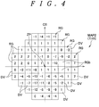
- the map image creator 15 reads a normal threshold ASV regarding each measurement point of the perimetry out of the memory 13 and obtains a difference between the threshold SV actually measured and the normal threshold ASV as a total deviation DV (dB), and generates a map image MAP2 on which the deviation value DV regarding each measurement point is indicated as shown in Fig.4 , corresponding to a fundus visual field range and indicates this image on the display 20.
- the normal threshold ASV may be a mean value of the measurement results of many subject eyes, or may be proper value, such as a median of the measurement results of the subject eyes since it is the threshold that is regarded as the normal value in each measurement point.
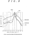
- the total deviation DV is a difference between a normal sensitivity curve NS indicated with the normal threshold ASV and the threshold SV actually measured as the measurement result of the subject eye 22a, as shown in Fig.9 .
- the range RG on which "0" is indicated as the total deviation value DV is the measurement point in which the measured threshold SV and the normal threshold ASV are equal to each other
- the range RG on which a positive number, such as "1” and “2", is indicated is the measurement point in which the measured threshold SV is higher than the normal threshold ASV in the sensitivity
- the range RG on which a negative number, such as "-1” and "-2" is indicated is the measurement point in which the measured threshold SV is lower than the normal threshold ASV in the sensitivity.
- the obtained threshold testing result SHR, the total deviation result THR, and their map images MAP1 and MAP2 are respectively stored in the ranges in the memory 13, attaching ID data corresponding to the subject eye 22a thereto as measurement data of the subject eye 22a of the examinee 22.
- the map image creator 15 reads the threshold SV of the subject eye 22a on each measurement point (each region RG) of the perimetry from the memory 13, and obtains a normal visual field pattern GS that corresponds to a sensitivity level of the subject eye 22a computed and estimated from the threshold SV as an estimated threshold PSV for each measurement point (each region RG) with a well-known method as shown in Fig. 9 .
- the estimated threshold PSV may be stored in the memory 13, corresponding to the measurement result of the subject eye 22a in such a manner the normal threshold ASV is amended in association with the sensitivity level (threshold) of each measurement point.
- a difference between the estimated threshold PSV obtained for each measurement point (each region RG) and threshold SV actually measured is a pattern deviation PDV (dB). That is, the pattern deviation PDV is a value that indicates a partial disorder of the visual field that is obtained in such a way that the normal value data amended according to the age of the examinee is subtracted from the threshold measured through the perimeter, and the total deviation representing thus obtained value is amended in consideration of the depression or the rise of the entire visual field.
- the map image creator 15 computes the difference between the measured threshold SV of the subject eye 22a on each measurement point and the estimated threshold PSV as the pattern deviation PDV, indicates the values PDV, corresponding to the ranges RG of the fundus on the respective measurement points so as to create a map image MAP3 and displays such a map on the display 20 as shown in Fig.5 .
- the range RG where the pattern deviation PDV is "0" is the measurement point where the measured threshold SV and the estimated threshold PSV is equal
- the range RG where a positive number, such as "1” and “2”, is indicated is the measurement point where the sensitivity of the measured threshold SV is higher than one of the estimated threshold PSV
- the range RG where a negative number, such as "-1” and "-2”, is indicated is the measurement point where the sensitivity of the measured threshold SV is lower than one of the estimated threshold PSV.
- the obtained pattern deviation result PHR and its map image MAP3 are stored in a range attaching ID data corresponding to the subject eye 22a in the memory 13 as the measurement data MD of the subject eye 22a of the examinee 22.
- the operator instructs the main controller 11 to extract the inspection points to be used in the subsequent perimetry through the input portion 19 on the basis of the map image MAP1 of the threshold SV, the map image MP2 of the total deviation result THR and the map image MAP3 of the pattern deviation result PHR on the subject eye 22a that are stored in the memory 13.
- the main controller 11 instructs the point extractor 16 to extracts 10 inspection points to be used in the subsequently perimetry.
- the point extractor 16 reads a point extracting program IPP out of the memory 13, and starts to extract the inspection points to be used in the subsequent perimetry.
- a degree of the progress of the disorder such as the Glaucoma
- the inspection is done at a higher frequency than in a conventional case (for instance, the inspection is done three times on one inspection point in order to improve the accuracy of the inspection although the inspection is generally done once).
- the inspection points are few and each inspection point is inspected in details (at a higher frequency) as mentioned above, so that it is possible to obtain uneven inspection results and to quickly judge progress of the disorder.
- an aim is to select 10 points that are anxious about the progress of the disorder from the inspection result of 54 through 76 points, to do the inspection once a month and to judge the progress of the disorder within half a year.
- the aim of the point extracting program IPP is to largely reduce the inspection points to be inspected in the subsequent perimetry from the number of the measurement points in the first normal perimetry (In a case of Fig.3 , 76 measurement points are set on each subject eye 22a) and to extract effective and sufficient 10 points from the first normal perimetry results, for instance.
- the point extractor 16 obtains a P value (probability) that represents each pattern deviation PDV of the pattern deviation result PHR of the subject eye 22a that was obtained in Fig.5 as a probability variable in Step S1 of the point extracting program IPP as shown in Fig.8 , and produces a map image MAP4 comprised of pattern deviation probability plot PDP as shown in Fig.6 and displays such a map on the display 20 in Step S2.
- the respective ranges RG are divided into four stages of P values, P ⁇ 5%, P ⁇ 2%, P ⁇ 1% and P ⁇ 0.5%, and it is judged that the lower the P value is, the higher the degree of an abnormality of the threshold SV is, that is, the degree of the abnormality of Glaucoma is making a progress.
- the respective ranges RG (measurement points) are divided into four stages as patterns according to the P value, and each range RG (measurement point) is filled with black color as the P value becomes lower. In a case where the P value is 5% or higher, it is judged the degree of the abnormality of the threshold SV is low, so that such a range is indicated with one black point in Fig.6 (such an range is excluded from the four stages).
- the point extracting program IPP enters Step S3, and the point extractor 16 selects an abnormal measurement point group (range RG group) where there are three measurement points or more having the P value that is lower than 5%, being adjacent to one another, excluding the ranges RG of the most peripheral portion, and at least one of these is P ⁇ 1%.
- an abnormal measurement point group range RG group
- Such a selection criterion is well-known as the criterion of visual field abnormality of Glaucoma by Anderson, but it is not necessary to always use such a criterion.
- the abnormality measurement point group (the range RG group) may be extracted and selected where there continuously exist a prescribed numbers of measurement points (the ranges RG) or more each of which P value is a first prescribed value or lower, and at least one of these points is a second prescribed value or lower, that is smaller than the first prescribed value.
- the range RG group there are two abnormality measurement point groups (the range RG group), P1 through P18 and P21 through 23, where there adjacently exist three ranges which P values are lower than 5% and at least one of these ranges which P value is lower than 1%.
- the measurement points (the ranges RG) P19 and P20 are ones of the visual field which are the most peripheral portion, so that these are excluded from the abnormal measurement point group even if the P value is lower than 5%.
- Step S3 two abnormal measurement point groups, the points P1 through P18 and P21 through P23 are extracted as inspection point candidates.
- the point extracting program IPP enters Step S4, and the point extractor 16 extracts the ranges RG in the order of the higher pattern deviation PDV (the better inspection result) from the extracted two abnormal measurement point groups, referring to the pattern deviation result PHR of Fig.5 until the measurement points to be measured in the subsequent perimetry reaches target number of inspection points.
- the measurement points are extracted up to ten points that are a one-fifth or lower regarding 50 measurement points or more (the ranges RG) that are set on the perimeter, corresponding to a fundus.
- the extraction of the ranges RG in the order of the higher pattern deviation PDV means the extraction of the ranges RG in the order of the better result of the pattern deviation PDV (but, the P values of such points are P ⁇ 5% as shown in Step S3, so that the disorder of the visual field clearly exists), that is, the extraction in the order of the few visual field abnormality.
- This is to extract the points judged that the disorder does not so progress at high probability, that is, the visual field abnormality is likely to progress in near future, of the points (the ranges RG) where the visual field abnormality exist, and such a point is the important in order to judge the visual field abnormality in a short period.
- the pattern deviation PDV of the range RG of the point P8 of the pattern deviation result PHR of Fig.5 is "-18", and it is known that the pattern deviation value PDV is extremely lower in comparison with the other points P1 through P18 and points P21 through P23. It is estimated that the visual field abnormality considerably progresses in such a range RG. On the contrary, the abnormality is less likely to progress more (to turn worse) in future, and even if the threshold SV in such a range RG is measured with a passage of time, its change is small and such a measurement does not conform to the purpose of the invention for diagnosing the visual field abnormality in a short period. Therefore, it is not preferable such a measurement point P8 is extracted and selected as the subsequent inspection measurement point.
- the point extracting program IPP enters Step S5 and the point extractor 16 judges whether the target number of inspection points to be extracted from the measurement points (ranges RG) reaches a prescribed number (in this case, 10 points) .
- Step S4 the program enters Step S6 and coordinates of the extracted measurement points (the ranges RG) are stored in the memory 13 as the measurement points in next perimetry.
- Step S4 the program enters Step S7, and a sector figure SEC that shows the measurement point group associated with an running direction of the retina nerve fibers is read out from the memory 13, and by referring to the sector figure SEC, the measurement points included in the same sector are extracted as a shortage from the inspection points excluding the abnormal measurement point group in the measurement points already extracted in the order of the lower (the worse) pattern deviation value PDV till the measurement points reaches 10 points.
- the sector figure SEC has sectors made by dividing the respective ranges RG (the measurement points) of the visual field to be measured of measurement coordinates CS, corresponding to a running of retina nerve fibers of the fundus as shown in Fig.7 , and in the case of Fig.7 , the respective regions are divided into 6 ranges, sectors SC1, SC2, SC3, SC4, SC5 and SC6 according to the running direction of the retina nerve fibers (blind point regions RGb are excluded).
- a lesion of the visual field abnormality such as the Glaucoma, is more likely to progress along the running direction of the retina nerve fibers, so that the measurement points in the sectors to which the measurement points (the ranges RG) already extracted in Step S4 belong are extracted from the inspection points excluding the abnormal measurement point group in the order of the lower (the worse) pattern deviation PDV till the measurement points reach 10 points .
- the 9 measurement points (the ranges RG) or lower are extracted in Step S4, it is judged that the degree of the visual field abnormality is not so high. Therefore, it is possible to properly detect the progress of the visual field abnormality at the subsequent perimetry with high possibility in such a way that the measurement points (the ranges RG) are extracted from ones along the running direction of the retina nerve fibers where the visual field abnormality is likely to progress in future, that is, from ones in the sectors to which the measurement points (ranges RG) already extracted belong excluding the abnormal measurement point group in the order of the lower (the worse) pattern deviation PDV in Step S7.
- the point extractor 16 judges in Step S8 of the point extracting program IPP whether the target number of the measurement points (the ranges RG) to be extracted reaches a prescribed number (in this case, 10 points).
- Step S7 When the 10 measurement points (the ranges RG) has been extracted in Step S7, the program enters Step S6 and the coordinates of the extracted measurement points (the ranges RG) are stored in the memory 13 as the measurement points in the next perimetry.
- the point extracting program IPP enters Step S9 and the point extractor 16 selects and extracts the measurement points from the ranges RG close to the measurement points (the ranges RG) already extracted in the order of the range RG closer to the measurement points (the ranges RG) already extracted on the map image MP4 of the pattern deviation probability plot PDP till the number of the measurement points reaches 10.
- the point extractor 16 selects and extracts the measurement points from the ranges RG close to the measurement points (the ranges RG) already extracted in the order of the range RG closer to the measurement points (the ranges RG) already extracted on the map image MP4 of the pattern deviation probability plot PDP till the number of the measurement points reaches 10.
- Step S9 When finishing the extraction of the 10 measurement points (the ranges RG) in Step S9, the program enters Step S6 and the coordinates of the extracted measurement points (the ranges RG) are stored in the memory 13 as the measurement points at the subsequent perimetry and the procedure of extracting the inspection points through the point extractor 16 finishes.
- the subsequent perimetry is done on the examinee every one month, for instance.
- This inspection interval is largely short in comparison with half a year or one year in a case of the normal perimetry, but it is sufficient to perform the subsequent perimetry on only 10 points extracted according to the point extracting program IPP of the 76 measurement points, for instance as shown in Fig.3 , without performing the inspection on all measurement points (the ranges RG) in the visual field dome 7. Then, it is possible to repeat the perimetry in a short period without an excessive burden on the examinee.
- a prescribed number of measurement points (the ranges RG) (in this case, 10 points) (the measurement points in the subsequent perimetry) extracted according to the point extracting program IPP are read out of the measurement result of the first perimetry for the subject eye 22a of the examinee stored in the memory 13 and the read is outputted on the display 20 or a printer (not shown) as re-inspection points, so that it is possible for the examiner to immediately measure the thresholds SV for the re-inspection points by presenting the stimuli in the visual field dome 7 on such re-inspection points only.
- the visual field measurer 10 may perform this re-inspection through automatically presenting the stimuli on the re-inspection points in order so as to obtain the thresholds SV.
- the pattern deviation result PHR is acquired from the perimetry result, the P value (probability) that represents each pattern deviation PDV as a probability variable comprising the pattern deviation result PHR is obtained, the pattern deviation probability plot PDP as shown in Fig.6 is generated, a target number of inspection points where the visual field abnormality seems to progress are extracted from these values according to the point extracting program IPP, and the extracted inspection points are stored in the memory 13 as information of the measurement points at the subsequent perimetry.
- the main controller 11 reads the information of the measurement points for the subsequent perimetry stored in the memory, and perform the inspection of the reaction threshold only on the measurement points on the subject eye 22a of the examinee. By doing so, it is possible to effectively perform the subsequent perimetry in a short period and in a short time, and at a higher frequency than an usual case (for instance, the inspection generally is done once on one inspection point, but the inspection is done three times in order to improve the inspection accuracy).
- the inspection points are concentrated on a part of the fundus visual field range since the inspection points are few in the perimetry of the invention.
- the examinee may predict that the stimulus appears on some range and may concentrate his (her) consciousness to such a range, so that its fixation state may be worse and the result different from the usual perimetry may be brought. If the inspection point is thus concentrated on a part of the range, it is possible to obtain the result similar to the usual perimetry in such a way that luminous points similar to the inspection points at the time of the inspection are presented to the range having no inspection point as dummy stimuli (the luminous points may be set brighter than the usual inspection) in order not to concentrate the examinee's consciousness to a part to the range.
- the entire visual field may be divided into four quadrants, for instance. If the inspection points are concentrated to some quadrant, or if there is the quadrant having no inspection point, the dummy stimulus may be presented to the quadrant having no inspection point with a certain probability.
Landscapes
- Life Sciences & Earth Sciences (AREA)
- Health & Medical Sciences (AREA)
- Medical Informatics (AREA)
- Biophysics (AREA)
- Ophthalmology & Optometry (AREA)
- Engineering & Computer Science (AREA)
- Biomedical Technology (AREA)
- Heart & Thoracic Surgery (AREA)
- Physics & Mathematics (AREA)
- Molecular Biology (AREA)
- Surgery (AREA)
- Animal Behavior & Ethology (AREA)
- General Health & Medical Sciences (AREA)
- Public Health (AREA)
- Veterinary Medicine (AREA)
- Eye Examination Apparatus (AREA)
Abstract
Description
- This invention relates to a perimeter capable of detecting a progress of visual field abnormality in associated with Glaucoma Optic Neurosis in a short period, reducing burdens on an examinee.
- In a perimetry (threshold testing), it is possible to measure the light sensitivity at each retina part, and it is possible to assess visual field progression in glaucoma by confirming the change of such a sensitivity over time.
- In the perimetry, while fixating some point, the examinee responds whether the examinee can perceive luminous points having various brightness presented in sequence on measurement points that are set on a periphery of some point. In the perimetry to be usually conducted, 54 through 76 measurement points are located, and it takes 3 to 15 minutes or so for one eye for such a perimetry, so that a heavy burden is imposed on the examinee.
- The Glaucoma that is a main target for the perimetry is the Glaucoma Optic Neurosis that is the visual field abnormality due to disappearance of progressive retinal ganglion cells. Therefore, it is necessary to detect a presence of the visual field abnormality and its degree as quickly as possible and to give a proper medical treatment.
- But, such a perimetry imposes a big burden on the examinee as mentioned above, and for this reason the perimetry is done at almost semiannual frequency.
- But, it is difficult to quickly assess the visual field progression at such a frequency, and a timing of appropriate treatment may be lost.
- An object of the invention is to provide a perimeter capable of appropriately assessing the visual field progression in a short period, restricting the burden on the examinee.
- The first aspect of the invention is a perimeter (2) capable of acquiring, as a threshold (SV), a value corresponding to a response result of an examinee (22) to an stimulus presented with various brightness, for a first number (54 or 72) of measurement points set across an entire measurement visual field of the ocular fundus of a subject eye (22a), displaying the threshold as a map image (MAP1) of a threshold testing result (SHR) on a display (20) and storing the same in a memory (13); comprising:
- a pattern deviation calculator (15) that obtains a pattern deviation (PDV) of the threshold (SV) relating to each measurement point (RG), from the threshold testing result (SHR);
- a probability map producer (15) that obtains a P value representing the obtained pattern deviation (PDV) for each measurement point (RG) as a probability variable, and generates a probability map image (MAP4) of a pattern probability plot (PDP) indicating the measurement points (RG) for the respective P values;
- a measurement point selector (16) that selects, from an abnormal measurement point group of points in the probability map image (MAP4) in which at least a prescribed number of measurement points (RG) (3 points) having a P value that is a first prescribed value (5%) or lower are continuous, and, of those, at least one point has the P value that is a second prescribed value (1%) or lower, smaller than the first prescribed value (5%), measurement points to be used as subsequent measurement points, until a prescribed number of points (10 points) have been reached; and
- a memory (13) that stores the subsequent measurement points selected through the measurement point selector (16), wherein the selection of the subsequent measurement points through the measurement point selector (16) is controlled in such a way that the measurement points (RG) are selected from ones comprising the abnormal measurement point group in order of those having a better pattern deviation (PDV).
- The second aspect of the invention is the perimeter (2), further comprising:
- an input portion (19) through which an identification code (ID and the like) on the subject eye (22a) can be inputted, and
- a re-inspection measurement point output portion (11) that, when the identification code is inputted in the input portion (19), reads the subsequent measurement points for the subject eye (22a) corresponding to the identification code out of the memory (13) and outputs the read out to an output portion (20).
- The third aspect of the invention is the perimeter, wherein the memory (13) stores a sector figure (SEC) that shows sectors formed by dividing the visual field to be measured so as to correspond to a running direction of retina nerve fibers, and the measurement point selector (16) has a sector extractor (16), the sector extractor reads and refers to the sector figure (SEC) stored in the memory (13) when the number of selecting the subsequent measurement points through the measurement point selector does not reach the prescribed number, and extracts, from the measurement points (RG) excluding the measurement points (RG) comprising the abnormality measurement point group in the sectors (SC1, SC2, SC3, SC4, SC5, SC6) to which the measurement points (RG) already measured belong, the subsequent measurement points in the order of the worse pattern deviation till the extracted number of measurement points reaches the prescribed number.
- The fourth aspect of the invention is the perimeter, wherein the prescribed number is 10.
- The fifth aspect of the invention is the perimeter, the measurement point selector (16) has a map image selector (16), when the number of selecting the subsequent measurement points through the measurement point selector (16) does not reach the prescribed number, the map image selector selects the measurement point (RG) close to the abnormality measurement point group in the probability map image (MAP4) of the pattern deviation probability plot (PDP) as the subsequent measurement points.
- The sixth aspect of the invention is the perimeter, wherein the measurement point selector (16) selects, from the abnormality measurement point group in the probability map image (MAP4), the measurement points in which at least a prescribed number of measurement points having P value that is 5% or lower are continuous, and of those at least one have the P value that is 1% or lower as the subsequent measurement points.
- The seventh aspect of the invention is the perimeter, wherein the measurement point selector (16) selects, from the abnormality measurement point group in the probability map image (MAP4), the measurement points in which at least three measurement points having P value that is 5% or lower are continuous, and of those at least one have the P value that is 1% or lower as the subsequent measurement points.
- According to the invention, the first perimetry is performed on the entire visual field of the subject eye (22a) so as to obtain the threshold testing result (SHR), the probability map image (MAP4) of the pattern deviation probability plot (PDP) is generated from the threshold testing result (SHR), the measurement points (RG) to be used as subsequent measurement points are selected from the abnormal measurement point group of points in which at least a first prescribed number (three) of measurement points (RG) having a P value that is smaller than a first prescribed value (5%) or lower are continuous, and of those, at least one point having the P value that is the second prescribed value (1%) or lower, smaller than the first prescribed value (5%), in the order of the better pattern deviation (PDV) till the number to be selected reaches a prescribed number (10 points) . By doing so, since the threshold testing is performed firstly on the entire visual field, the range (RG) where the degree of the disorder is relatively low (the pattern deviation (PDV) is good) and the disorder is likely to progress at higher possibility, that is, the range (RG) where the change of the threshold with a passage of time is easy to be judged in the subsequent inspection is effectively extracted from the ranges (RG) where the P value is small, and the progress of the visual field abnormality is anxious about. And, it is possible to select the measurement points for the subsequent perimetry from the extracted ranges and to store the selected as information of the measurement points of the subsequent perimetry in the memory (13).
- At the time of the subsequent perimetry, the information of the measurement points for the subsequent perimetry is read out from the memory (13), the reaction threshold testing is done on the eye (22a) of the examinee only on the measurement points read out. By doing so, it is possible to effectively perform the subsequent perimetry in a short period and in a short time, and to perform the perimetry at higher frequency than as a usual case (three times, for instance, although the perimetry is usually done once on one inspection point) so as to improve the accuracy of the inspection.
- Then, it is possible to judge the progress of the disorder, such as Glaucoma, earlier than usual, to lighten the burden on the examinee due to small number of measurement points for the inspection, to inspect each inspection point in detail (at high frequency), and to obtain varied inspection result and to judge the progress earlier.
- In a case where a prescribed number of measurement points (10 points) are not selected as the measurement points for the subsequent inspection from only the probability map image (MAP4) of the pattern deviation probability plot (PDP), it is judged that the degree of the visual field abnormality is not so high. Then, it is possible to select the ranges (RG) where the degree of the disorder is relatively high as the measurement points for the subsequent inspection along the running direction of the retina nerve fibers where the visual field abnormality is likely to progress in near future, and to improve the accuracy of the subsequent perimetry in such a way that the sector figure (SEC) that shows sectors divided along the running direction of the retina nerve fibers is referred, and a prescribed number of measurement points are extracted as the measurement points for the subsequent perimetry within the sectors (SC1, SC2, SC3, SC4, SC5, SC6) to which the measurement points (RG) already selected belong, and within the measurement points that are not the abnormal measurement point group, in the order of the worse pattern deviation (in the order of the more serious condition, but the visual field abnormality is not so high) till the selected reaches the prescribed number.
- The number in parentheses shows the corresponding element in the drawings for the sake of convenience, accordingly, the descriptions are not restricted and bound by the descriptions on the drawings.
-
-
Fig. 1 is a perspective view that shows an example of a perimeter to which the invention is applied. -
Fig.2 is a control block diagram that shows an example of control portions of the perimeter ofFig.1 . -
Fig.3 is a map image of a threshold inspection result of a perimetry on a subject eye. -
Fig.4 is a map image of a total deviation with regard to the threshold inspection result of the perimetry on the subject eye. -
Fig.5 is a map image of a pattern deviation with regard to the threshold inspection result of the perimetry on the subject eye. -
Fig. 6 is a map image of a pattern deviation probability plot with regard to the threshold inspection result of the perimetry on the subject eye. -
Fig.7 is a map image that shows inspection point sectors. -
Fig.8 is a flowchart that shows an example of point extracting program. -
Fig. 9 is a view showing a relation between the total deviation and the pattern deviation. - Embodiments of the invention are mentioned, referring to appended drawings.
- As shown in
Fig.1 , aperimeter 2 has amain body 3 the whole of which is in the shape of a box, and achin rest 5 and aforehead pad 6 are provided at afront face 3a of themain body 3. Aresponse switch 1 is attachably and detachably located on a right side ofFig.1 of themain body 3 through aconnection flex 9, and avisual field dome 7 in a semi-spherical shape through which stimuli are presented, is provided at a front hand of thechin rest 5 and thehead rest 6, that is, inside themain body 3 on a back side of a paper ofFig.1 . Thevisual field dome 7 is configured so as to project stimulus for perimetry (not shown) at optional positions in thevisual field dome 7 through avisual field measurer 10 as shown inFig.2 that is built in themain body 3. - Besides, as shown in
Fig.2 , acontroller 8 of theperimeter 2 is provided inside themain body 3, and thecontroller 8 has amain controller 11. Amemory 13, the above-mentionedvisual field measurer 10, amap image creator 15, apoint extractor 16, aninput portion 19, such as a keyboard, and adisplay 20 are connected with themain controller 11 via abus line 12. A control block diagram as shown inFig.2 shows only portions that relate to the invention and does not show the other constitutional portions of theperimeter 2 that are not related to the invention. - The
perimeter 2 has the above-mentioned structure. In order to measure a visual field ofsubject eyes 22a of anexaminee 22 so as to use for diagnoses for a glaucoma and the like, an examinee is invited to put his (her) chin on thechin rest 5 and to contact his (her) forehead with thehead rest 6 so as to be pressed against such a pad such that thesubject eye 22a of theexaminee 22 is located at a predetermined perimetry position, as shown inFig. 2 . - When an operator instructs the
perimeter 2 to start a visual field measurement operation through theinput portion 19 in the afore-mentioned state, themain controller 11 instructs thevisual field measurer 10 to measure the visual field of thesubject eye 22a. Receiving such an instruction, thevisual field measurer 10 presents the stimuli (not shown) in order at proper positions inside thevisual field dome 7 with a well-known method of the perimetry. At the results, as shown inFig.3 , minimum values of brightness of the stimuli to which the examinee can respond regarding two or more measurement points (for instance, 50 measurement points or more, such as 54 points, and 76 points, which are indicated with many square ranges RG in the figure and are set, corresponding to an entire range of a retina of a fundus, that is, the entire range of the visual field) on a measurement coordinate system CS are measured and collected, and these values, threshold SV (dB), are indicated on thedisplay 20 with numeral numbers as a map image MAP1 and are stored in thememory 13. As a method of obtaining the threshold SV, it is sufficient to adopt a value corresponding to a response result to the stimuli presented to theexaminee 22 with various brightness. Otherwise, the other methods may be adopted. One method is to collect the response reaction to the light spots (the stimuli) to be presented to theexaminee 22 with various brightness and to estimate the threshold SV (dB) from such a response reaction. The map image MAP1 is comprised of two or more ranges RG (50 ranges or more, such as 54 ranges and 76 ranges) that correspond to the above-mentioned measurement points. An origin ZP of the measurement coordinate system CS in the figure that is used for the perimetry is set, corresponding to a center position of a macula of thesubject eye 22a, and a portion where the threshold SV < 0 in the figure is a point (a range) to which the examinee does not respond (to which the examinee is not able to perceive) . In case ofFig.3 , the measurement points that correspond to the ranges RG are ones that correspond to blind spots. The range RG (not shown) indicated as the threshold "0 (zero)" means that the examinee perceived the stimulus having 0dB brightness. - When the examinee perceives the stimulus presented on the
visual field dome 7 through thesubject eye 22a at the time of the perimetry, he (or she) operates theresponse switch 1. If not perceived, the examinee does not operate theresponse switch 1. So, it is possible for thevisual field measurer 10 to obtain the measurement results regarding the respective measurement points, as shown inFig.3 , relating the state of the operation of theresponse switch 1 and the position and the brightness of the stimulus inside thevisual field dome 7 at this time to each other. In the measurement results ofFig.3 , the value of the threshold SV is a reaction threshold of thesubject eye 22a, and the measured result is referred to as threshold testing result SHR for this reason. - After thus obtaining the threshold testing result SHR regarding the
subject eye 22a, themain controller 11 instructs themap image creator 15 to compute a total deviation and a pattern deviation regarding each measurement point of the obtained threshold testing result SHR and to display a total deviation result THR and a pattern deviation result PHR. - For the total deviation result THR, the
map image creator 15 reads a normal threshold ASV regarding each measurement point of the perimetry out of thememory 13 and obtains a difference between the threshold SV actually measured and the normal threshold ASV as a total deviation DV (dB), and generates a map image MAP2 on which the deviation value DV regarding each measurement point is indicated as shown inFig.4 , corresponding to a fundus visual field range and indicates this image on thedisplay 20. In such a case, the normal threshold ASV may be a mean value of the measurement results of many subject eyes, or may be proper value, such as a median of the measurement results of the subject eyes since it is the threshold that is regarded as the normal value in each measurement point. The total deviation DV is a difference between a normal sensitivity curve NS indicated with the normal threshold ASV and the threshold SV actually measured as the measurement result of thesubject eye 22a, as shown inFig.9 . - In the map image MAP2 of the total deviation result THR of
Fig. 4 , the range RG on which "0" is indicated as the total deviation value DV is the measurement point in which the measured threshold SV and the normal threshold ASV are equal to each other, and the range RG on which a positive number, such as "1" and "2", is indicated is the measurement point in which the measured threshold SV is higher than the normal threshold ASV in the sensitivity, and the range RG on which a negative number, such as "-1" and "-2", is indicated is the measurement point in which the measured threshold SV is lower than the normal threshold ASV in the sensitivity. The obtained threshold testing result SHR, the total deviation result THR, and their map images MAP1 and MAP2 are respectively stored in the ranges in thememory 13, attaching ID data corresponding to thesubject eye 22a thereto as measurement data of thesubject eye 22a of theexaminee 22. - Besides, for the pattern deviation result PHR, the
map image creator 15 reads the threshold SV of thesubject eye 22a on each measurement point (each region RG) of the perimetry from thememory 13, and obtains a normal visual field pattern GS that corresponds to a sensitivity level of thesubject eye 22a computed and estimated from the threshold SV as an estimated threshold PSV for each measurement point (each region RG) with a well-known method as shown inFig. 9 . In such a case, the estimated threshold PSV may be stored in thememory 13, corresponding to the measurement result of thesubject eye 22a in such a manner the normal threshold ASV is amended in association with the sensitivity level (threshold) of each measurement point. A difference between the estimated threshold PSV obtained for each measurement point (each region RG) and threshold SV actually measured is a pattern deviation PDV (dB). That is, the pattern deviation PDV is a value that indicates a partial disorder of the visual field that is obtained in such a way that the normal value data amended according to the age of the examinee is subtracted from the threshold measured through the perimeter, and the total deviation representing thus obtained value is amended in consideration of the depression or the rise of the entire visual field. - This is a procedure for detecting the partial disorder of visual field that is difficult to be judged in the total deviation with the normal threshold ASV in such a way that a depression or a rise of the entire visual field is amended by the estimated threshold PSV that corresponds to a lowering or a rise of the sensitivity of the
subject eye 22a which is indicated by the threshold SV of thesubject eye 22a actually measured. Themap image creator 15 computes the difference between the measured threshold SV of thesubject eye 22a on each measurement point and the estimated threshold PSV as the pattern deviation PDV, indicates the values PDV, corresponding to the ranges RG of the fundus on the respective measurement points so as to create a map image MAP3 and displays such a map on thedisplay 20 as shown inFig.5 . In the map image MAP3 of the pattern deviation result PHR ofFig.5 , the range RG where the pattern deviation PDV is "0" is the measurement point where the measured threshold SV and the estimated threshold PSV is equal, the range RG where a positive number, such as "1" and "2", is indicated is the measurement point where the sensitivity of the measured threshold SV is higher than one of the estimated threshold PSV, and the range RG where a negative number, such as "-1" and "-2", is indicated is the measurement point where the sensitivity of the measured threshold SV is lower than one of the estimated threshold PSV. The obtained pattern deviation result PHR and its map image MAP3 are stored in a range attaching ID data corresponding to thesubject eye 22a in thememory 13 as the measurement data MD of thesubject eye 22a of theexaminee 22. - After thus finishing the first perimetry on the
subject eye 22a, the operator instructs themain controller 11 to extract the inspection points to be used in the subsequent perimetry through theinput portion 19 on the basis of the map image MAP1 of the threshold SV, the map image MP2 of the total deviation result THR and the map image MAP3 of the pattern deviation result PHR on thesubject eye 22a that are stored in thememory 13. Receiving such an instruction, themain controller 11 instructs thepoint extractor 16 toextracts 10 inspection points to be used in the subsequently perimetry. - The
point extractor 16 reads a point extracting program IPP out of thememory 13, and starts to extract the inspection points to be used in the subsequent perimetry. According to the invention, it is possible to judge a degree of the progress of the disorder, such as the Glaucoma, earlier than in a conventional case in such a manner that the inspection is effectively executed in a short time only on the inspection points that are anxious about the progress of the disorder on the basis of the normal perimetry results, and the inspection is done at a higher frequency than in a conventional case (for instance, the inspection is done three times on one inspection point in order to improve the accuracy of the inspection although the inspection is generally done once). Besides, the inspection points are few and each inspection point is inspected in details (at a higher frequency) as mentioned above, so that it is possible to obtain uneven inspection results and to quickly judge progress of the disorder. - For instance, an aim is to select 10 points that are anxious about the progress of the disorder from the inspection result of 54 through 76 points, to do the inspection once a month and to judge the progress of the disorder within half a year. Then, the aim of the point extracting program IPP is to largely reduce the inspection points to be inspected in the subsequent perimetry from the number of the measurement points in the first normal perimetry (In a case of
Fig.3 , 76 measurement points are set on eachsubject eye 22a) and to extract effective and sufficient 10 points from the first normal perimetry results, for instance. - The
point extractor 16 obtains a P value (probability) that represents each pattern deviation PDV of the pattern deviation result PHR of thesubject eye 22a that was obtained inFig.5 as a probability variable in Step S1 of the point extracting program IPP as shown inFig.8 , and produces a map image MAP4 comprised of pattern deviation probability plot PDP as shown inFig.6 and displays such a map on thedisplay 20 in Step S2. In the pattern deviation probability plot PDP, the respective ranges RG are divided into four stages of P values, P < 5%, P < 2%, P < 1% and P < 0.5%, and it is judged that the lower the P value is, the higher the degree of an abnormality of the threshold SV is, that is, the degree of the abnormality of Glaucoma is making a progress. As shown in an explanation ofFig.6 , the respective ranges RG (measurement points) are divided into four stages as patterns according to the P value, and each range RG (measurement point) is filled with black color as the P value becomes lower. In a case where the P value is 5% or higher, it is judged the degree of the abnormality of the threshold SV is low, so that such a range is indicated with one black point inFig.6 (such an range is excluded from the four stages). - After the pattern deviation probability plot PDP is thus indicated with the map image MAP4, the point extracting program IPP enters Step S3, and the
point extractor 16 selects an abnormal measurement point group (range RG group) where there are three measurement points or more having the P value that is lower than 5%, being adjacent to one another, excluding the ranges RG of the most peripheral portion, and at least one of these is P < 1%. Such a selection criterion is well-known as the criterion of visual field abnormality of Glaucoma by Anderson, but it is not necessary to always use such a criterion. The abnormality measurement point group (the range RG group) may be extracted and selected where there continuously exist a prescribed numbers of measurement points (the ranges RG) or more each of which P value is a first prescribed value or lower, and at least one of these points is a second prescribed value or lower, that is smaller than the first prescribed value. - In a case of
Fig. 6 , there are two abnormality measurement point groups (the range RG group), P1 through P18 and P21 through 23, where there adjacently exist three ranges which P values are lower than 5% and at least one of these ranges which P value is lower than 1%. In such a case, the measurement points (the ranges RG) P19 and P20 are ones of the visual field which are the most peripheral portion, so that these are excluded from the abnormal measurement point group even if the P value is lower than 5%. Then, in Step S3, two abnormal measurement point groups, the points P1 through P18 and P21 through P23 are extracted as inspection point candidates. - Subsequently, the point extracting program IPP enters Step S4, and the
point extractor 16 extracts the ranges RG in the order of the higher pattern deviation PDV (the better inspection result) from the extracted two abnormal measurement point groups, referring to the pattern deviation result PHR ofFig.5 until the measurement points to be measured in the subsequent perimetry reaches target number of inspection points. In this embodiment, the measurement points are extracted up to ten points that are a one-fifth or lower regarding 50 measurement points or more (the ranges RG) that are set on the perimeter, corresponding to a fundus. - The extraction of the ranges RG in the order of the higher pattern deviation PDV means the extraction of the ranges RG in the order of the better result of the pattern deviation PDV (but, the P values of such points are P < 5% as shown in Step S3, so that the disorder of the visual field clearly exists), that is, the extraction in the order of the few visual field abnormality. This is to extract the points judged that the disorder does not so progress at high probability, that is, the visual field abnormality is likely to progress in near future, of the points (the ranges RG) where the visual field abnormality exist, and such a point is the important in order to judge the visual field abnormality in a short period. For instance, the pattern deviation PDV of the range RG of the point P8 of the pattern deviation result PHR of
Fig.5 is "-18", and it is known that the pattern deviation value PDV is extremely lower in comparison with the other points P1 through P18 and points P21 through P23. It is estimated that the visual field abnormality considerably progresses in such a range RG. On the contrary, the abnormality is less likely to progress more (to turn worse) in future, and even if the threshold SV in such a range RG is measured with a passage of time, its change is small and such a measurement does not conform to the purpose of the invention for diagnosing the visual field abnormality in a short period. Therefore, it is not preferable such a measurement point P8 is extracted and selected as the subsequent inspection measurement point. - In a similar meaning, in the ranges RG where DV ≤ -20 (dB) (concrete numeral value can be properly set) that is known by referring to the total deviation result THR of
Fig.4 at the time of extracting the measurement points in Step S4, the blind spots are deep, and it is predicted that the disorder is hard to progress in such points (that is, it is difficult to diagnose the progress of the visual field abnormality in a short period), so that these points may be excluded from the procedure of extracting the measurement points. - Subsequently, the point extracting program IPP enters Step S5 and the
point extractor 16 judges whether the target number of inspection points to be extracted from the measurement points (ranges RG) reaches a prescribed number (in this case, 10 points) . - In a case where such an extraction of 10 measurement points (the ranges RG) is finished in Step S4, the program enters Step S6 and coordinates of the extracted measurement points (the ranges RG) are stored in the
memory 13 as the measurement points in next perimetry. - In a case where 9 measurement points (the ranges RG) or lower (including zero point) are extracted in Step S4, the program enters Step S7, and a sector figure SEC that shows the measurement point group associated with an running direction of the retina nerve fibers is read out from the
memory 13, and by referring to the sector figure SEC, the measurement points included in the same sector are extracted as a shortage from the inspection points excluding the abnormal measurement point group in the measurement points already extracted in the order of the lower (the worse) pattern deviation value PDV till the measurement points reaches 10 points. - The sector figure SEC has sectors made by dividing the respective ranges RG (the measurement points) of the visual field to be measured of measurement coordinates CS, corresponding to a running of retina nerve fibers of the fundus as shown in
Fig.7 , and in the case ofFig.7 , the respective regions are divided into 6 ranges, sectors SC1, SC2, SC3, SC4, SC5 and SC6 according to the running direction of the retina nerve fibers (blind point regions RGb are excluded). A lesion of the visual field abnormality, such as the Glaucoma, is more likely to progress along the running direction of the retina nerve fibers, so that the measurement points in the sectors to which the measurement points (the ranges RG) already extracted in Step S4 belong are extracted from the inspection points excluding the abnormal measurement point group in the order of the lower (the worse) pattern deviation PDV till the measurement points reach 10 points . - If the 9 measurement points (the ranges RG) or lower are extracted in Step S4, it is judged that the degree of the visual field abnormality is not so high. Therefore, it is possible to properly detect the progress of the visual field abnormality at the subsequent perimetry with high possibility in such a way that the measurement points (the ranges RG) are extracted from ones along the running direction of the retina nerve fibers where the visual field abnormality is likely to progress in future, that is, from ones in the sectors to which the measurement points (ranges RG) already extracted belong excluding the abnormal measurement point group in the order of the lower (the worse) pattern deviation PDV in Step S7.
- After finishing the extraction of the measurement points along the sector figure SEC in Step S7, the
point extractor 16 judges in Step S8 of the point extracting program IPP whether the target number of the measurement points (the ranges RG) to be extracted reaches a prescribed number (in this case, 10 points). - When the 10 measurement points (the ranges RG) has been extracted in Step S7, the program enters Step S6 and the coordinates of the extracted measurement points (the ranges RG) are stored in the
memory 13 as the measurement points in the next perimetry. - If the 9 measurement points (the ranges RG) or lower are extracted in Step S7, the point extracting program IPP enters Step S9 and the
point extractor 16 selects and extracts the measurement points from the ranges RG close to the measurement points (the ranges RG) already extracted in the order of the range RG closer to the measurement points (the ranges RG) already extracted on the map image MP4 of the pattern deviation probability plot PDP till the number of the measurement points reaches 10. When extracting the measurement points (the ranges RG) close to ones having the low (bad) pattern deviation PDV from the measurement points already extracted, it is possible to extract the measurement points where the visual field abnormality progress in future with high probability. - When finishing the extraction of the 10 measurement points (the ranges RG) in Step S9, the program enters Step S6 and the coordinates of the extracted measurement points (the ranges RG) are stored in the
memory 13 as the measurement points at the subsequent perimetry and the procedure of extracting the inspection points through thepoint extractor 16 finishes. - After finishing the extraction of a prescribed number of measurement points (the ranges RG) (10 points in this embodiment) to be used at the subsequent perimetry through the
point extractor 16, the subsequent perimetry is done on the examinee every one month, for instance. This inspection interval is largely short in comparison with half a year or one year in a case of the normal perimetry, but it is sufficient to perform the subsequent perimetry on only 10 points extracted according to the point extracting program IPP of the 76 measurement points, for instance as shown inFig.3 , without performing the inspection on all measurement points (the ranges RG) in thevisual field dome 7. Then, it is possible to repeat the perimetry in a short period without an excessive burden on the examinee. - When inputting the identification code, such as a ID of the examinee, through the
input portion 19 at the subsequent perimetry, a prescribed number of measurement points (the ranges RG) (in this case, 10 points) (the measurement points in the subsequent perimetry) extracted according to the point extracting program IPP are read out of the measurement result of the first perimetry for thesubject eye 22a of the examinee stored in thememory 13 and the read is outputted on thedisplay 20 or a printer (not shown) as re-inspection points, so that it is possible for the examiner to immediately measure the thresholds SV for the re-inspection points by presenting the stimuli in thevisual field dome 7 on such re-inspection points only. Thevisual field measurer 10 may perform this re-inspection through automatically presenting the stimuli on the re-inspection points in order so as to obtain the thresholds SV. - Although it is necessary to inspect the whole ranges RG of the visual field as usual in the first perimetry, according to the invention, the pattern deviation result PHR is acquired from the perimetry result, the P value (probability) that represents each pattern deviation PDV as a probability variable comprising the pattern deviation result PHR is obtained, the pattern deviation probability plot PDP as shown in
Fig.6 is generated, a target number of inspection points where the visual field abnormality seems to progress are extracted from these values according to the point extracting program IPP, and the extracted inspection points are stored in thememory 13 as information of the measurement points at the subsequent perimetry. And, at the time of the subsequent perimetry, themain controller 11 reads the information of the measurement points for the subsequent perimetry stored in the memory, and perform the inspection of the reaction threshold only on the measurement points on thesubject eye 22a of the examinee. By doing so, it is possible to effectively perform the subsequent perimetry in a short period and in a short time, and at a higher frequency than an usual case (for instance, the inspection generally is done once on one inspection point, but the inspection is done three times in order to improve the inspection accuracy). - Then, it is possible to judge the progress of the disorder, such as Glaucoma, earlier than usual, to inspect each inspection point in detail (at high frequency) due to small number of the inspection points, and to obtain varied inspection result and to judge the progress earlier.
- In some cases, the inspection points are concentrated on a part of the fundus visual field range since the inspection points are few in the perimetry of the invention. In such a case, the examinee may predict that the stimulus appears on some range and may concentrate his (her) consciousness to such a range, so that its fixation state may be worse and the result different from the usual perimetry may be brought. If the inspection point is thus concentrated on a part of the range, it is possible to obtain the result similar to the usual perimetry in such a way that luminous points similar to the inspection points at the time of the inspection are presented to the range having no inspection point as dummy stimuli (the luminous points may be set brighter than the usual inspection) in order not to concentrate the examinee's consciousness to a part to the range.
- If the inspection points are concentrated to a part of the range due to the result of selection of the inspection points, the entire visual field may be divided into four quadrants, for instance. If the inspection points are concentrated to some quadrant, or if there is the quadrant having no inspection point, the dummy stimulus may be presented to the quadrant having no inspection point with a certain probability.
-
- 2 ...... perimeter
- 11 ...... main controller (display)
- 13 ...... memory
- 15 ...... pattern deviation calculator, probability map producer (map image creator)
- 16 ...... measurement point selector, sector extractor, map image selector (point extractor)
- 19 ...... input portion (input portion)
- 20 ...... display
- 22 ...... examinee
- 22a ...... subject eye
- RG ...... measurement point (range)
- SC1, SC2, SC3, SC4, SC5, SC6 ...... sector
- SV ...... threshold
- PDP ...... pattern deviation probability plot
- PDV ...... pattern deviation
- SEC ...... sector figure
- SHR ...... threshold inspection result
- MAP1, MAP2, MAP3, MAP4 ...... map image
Claims (7)
- A perimeter capable of acquiring, as a threshold, a value corresponding to a response result of an examinee to an stimulus presented with various brightness, for a first number of measurement points set across an entire measurement visual field of the ocular fundus of a subject eye, displaying the threshold as a map image of a threshold testing result and storing the same in a memory; comprising:a pattern deviation calculator that obtains a pattern deviation of the threshold relating to each measurement point, from the threshold testing result;a probability map producer that obtains a P value representing the obtained pattern deviation for each measurement point as a probability variable, and generates a probability map image of a pattern probability plot indicating the measurement points for the respective P values;a measurement point selector that selects, from an abnormal measurement point group of points in the probability map image in which at least a prescribed number of measurement points having a P value that is a first prescribed value or lower are continuous, and, of those, at least one point has the P value that is a second prescribed value or lower, smaller than the first prescribed value, measurement points to be used as subsequent measurement points, until a prescribed number of points have been reached; anda memory that stores the subsequent measurement points selected through the measurement point selector, wherein the selection of the subsequent measurement points through the measurement point selector is controlled in such a way that the measurement points are selected from ones comprising the abnormal measurement point group in order of those having a better pattern deviation.
- The perimeter according to claim 1, further comprising:an input portion through which an identification code on the subject eye can be inputted, anda re-inspection measurement point output that, when the identification code is inputted in the input portion, reads the subsequent measurement points for the subject eye corresponding to the identification code out of the memory and outputs the read out to an output portion.
- The perimeter according to claim 1, wherein the memory stores a sector figure that shows sectors formed by dividing the visual field to be measured so as to correspond to a running direction of retina nerve fibers, and the measurement point selector has a sector extractor, the sector extractor reads and refers to the sector figure stored in the memory when the number of selecting the subsequent measurement points through the measurement point selector does not reach the prescribed number, and extracts, from the measurement points excluding the measurement points comprising the abnormality measurement point group in the sectors to which the measurement points already measured belong, the subsequent measurement points in the order of the worse pattern deviation till the extracted number of measurement points reaches the prescribed number.
- The perimeter according to claim 1, wherein the prescribed number is 10.
- The perimeter according to claim 1 or 3, the measurement point selector has a map image selector, when the number of selecting the subsequent measurement points through the measurement point selector does not reach the prescribed number, the map image selector selects the measurement point close to the abnormality measurement point group in the probability map image of the pattern deviation probability plot as the subsequent inspection measurement point.
- The perimeter according to claim 1, wherein the measurement point selector selects, from the abnormality measurement point group in the probability map image, the measurement points in which at least a prescribed number of measurement points having P value that is 5% or lower are continuous, and of those at least one have the P value that is 1% or lower as the subsequent measurement points.
- The perimeter according to claim 6, wherein the measurement point selector selects, from the abnormality measurement point group in the probability map image, the measurement points in which at least three measurement points having P value that is 5% or lower are continuous, and of those at least one have the P value that is 1% or lower as the subsequent measurement points.
Applications Claiming Priority (2)
| Application Number | Priority Date | Filing Date | Title |
|---|---|---|---|
| JP2017142538 | 2017-07-24 | ||
| PCT/JP2018/027442 WO2019021986A1 (en) | 2017-07-24 | 2018-07-23 | Perimeter |
Publications (3)
| Publication Number | Publication Date |
|---|---|
| EP3659493A1 true EP3659493A1 (en) | 2020-06-03 |
| EP3659493A4 EP3659493A4 (en) | 2021-04-07 |
| EP3659493B1 EP3659493B1 (en) | 2024-01-03 |
Family
ID=65039745
Family Applications (1)
| Application Number | Title | Priority Date | Filing Date |
|---|---|---|---|
| EP18837922.6A Active EP3659493B1 (en) | 2017-07-24 | 2018-07-23 | Perimeter |
Country Status (4)
| Country | Link |
|---|---|
| US (1) | US11426064B2 (en) |
| EP (1) | EP3659493B1 (en) |
| JP (1) | JP7260729B2 (en) |
| WO (1) | WO2019021986A1 (en) |
Family Cites Families (19)
| Publication number | Priority date | Publication date | Assignee | Title |
|---|---|---|---|---|
| US5461435A (en) * | 1993-05-05 | 1995-10-24 | Rootzen; Holger | Method and an apparatus for checking the thresholds of a subject's perception of visual stimuli |
| JP3317754B2 (en) * | 1993-09-16 | 2002-08-26 | 株式会社トプコン | Perimeter measurement device |
| US6527391B1 (en) * | 1998-12-30 | 2003-03-04 | Anders Heijl | Method and an apparatus for performing a visual field test, and computer programs for processing the results thereof |
| US7309128B2 (en) * | 2002-09-20 | 2007-12-18 | Centrofuse Technologies, Llc | Automated stereocampimeter and related method for improved measurement of the visual field |
| JP4250048B2 (en) * | 2003-09-30 | 2009-04-08 | 株式会社ニデック | Perimeter |
| GB0606680D0 (en) * | 2006-04-03 | 2006-05-10 | Univ Cardiff | Method of and apparatus for detecting degradation of visual performance |
| JP4806602B2 (en) * | 2006-08-09 | 2011-11-02 | 興和株式会社 | Perimeter |
| JP4896621B2 (en) * | 2006-08-09 | 2012-03-14 | 興和株式会社 | Perimeter |
| DE102008033587A1 (en) * | 2007-07-17 | 2009-04-02 | Heidelberg Engineering Gmbh | Method and device for evaluating the visual field |
| US20110190657A1 (en) * | 2009-08-10 | 2011-08-04 | Carl Zeiss Meditec, Inc. | Glaucoma combinatorial analysis |
| GB201007697D0 (en) * | 2010-05-06 | 2010-06-23 | Ucl Business Plc | A supra-threshold test for use in detecting sensitivity loss across the field of vision |
| JP5563087B2 (en) * | 2010-08-24 | 2014-07-30 | 興和株式会社 | Visual field inspection system |
| US9433346B2 (en) * | 2011-11-21 | 2016-09-06 | Gobiquity, Inc. | Circular preferential hyperacuity perimetry video game to monitor macular and retinal diseases |
| EP2883492B1 (en) * | 2012-08-10 | 2022-08-24 | Kowa Company Ltd. | Perimeter |
| ES2936340T3 (en) * | 2013-06-25 | 2023-03-16 | Oculus Optikgeraete Gmbh | Analysis procedure |
| US9883793B2 (en) * | 2013-08-23 | 2018-02-06 | The Schepens Eye Research Institute, Inc. | Spatial modeling of visual fields |
| EP3106082B1 (en) * | 2014-02-12 | 2020-04-22 | Kowa Company, Ltd. | Perimeter |
| PL3402388T3 (en) * | 2016-01-12 | 2022-02-21 | Tel Hashomer Medical Research Infrastructure And Services Ltd. | System and method for performing objective perimetry and diagnosis of patients with retinitis pigmentosa and other ocular diseases |
| US20180014724A1 (en) * | 2016-07-18 | 2018-01-18 | Dariusz Wroblewski | Method and System for Analysis of Diagnostic Parameters and Disease Progression |
-
2018
- 2018-07-23 WO PCT/JP2018/027442 patent/WO2019021986A1/en not_active Ceased
- 2018-07-23 US US16/633,548 patent/US11426064B2/en active Active
- 2018-07-23 EP EP18837922.6A patent/EP3659493B1/en active Active
- 2018-07-23 JP JP2019532584A patent/JP7260729B2/en active Active
Also Published As
| Publication number | Publication date |
|---|---|
| US11426064B2 (en) | 2022-08-30 |
| JPWO2019021986A1 (en) | 2020-07-02 |
| US20200205655A1 (en) | 2020-07-02 |
| EP3659493A4 (en) | 2021-04-07 |
| WO2019021986A1 (en) | 2019-01-31 |
| EP3659493B1 (en) | 2024-01-03 |
| JP7260729B2 (en) | 2023-04-19 |
Similar Documents
| Publication | Publication Date | Title |
|---|---|---|
| Vizzeri et al. | Effect of signal strength and improper alignment on the variability of stratus optical coherence tomography retinal nerve fiber layer thickness measurements | |
| US12471771B2 (en) | Visual testing using mobile devices | |
| Duncan et al. | Retinotopic organization of primary visual cortex in glaucoma: Comparing fMRI measurements of cortical function with visual field loss | |
| Prentašić et al. | Diabetic retinopathy image database (DRiDB): a new database for diabetic retinopathy screening programs research | |
| EP2883492B1 (en) | Perimeter | |
| CN104382552A (en) | Equipment and method for testing comprehensive vision functions | |
| US8425039B2 (en) | Perimetric method | |
| KR101654265B1 (en) | Individual-based visual field testing method and device of the same | |
| EP3659493B1 (en) | Perimeter | |
| JP5636550B2 (en) | Lens image analyzer | |
| KR20200139728A (en) | Apparatus and method for testing automatic regulation of metabolism | |
| CN113712500A (en) | Integrated self-response whole-course vision measurement system and measurement method thereof | |
| EP3629883B1 (en) | Device and method for the evaluation of visual abilities | |
| JP5955349B2 (en) | Analysis method | |
| US7367674B2 (en) | Perimeter and a method for operating a perimeter | |
| US20170332930A1 (en) | System and method for ecg signal processing | |
| RU2788962C2 (en) | System and method for digital measurement of characteristics of stereoscopic vision | |
| JP2025072551A (en) | Visual field testing method, visual field testing device, and visual field testing program | |
| WO2025027297A1 (en) | Perimetry apparatus | |
| Shajari | Testing of Visual Function: Visual Acuity, Refraction, Contrast Sensitivity | |
| Crabb | Visual Fields | |
| KR20230081189A (en) | Pupillary light reflex measurement method using cell phone | |
| Mills | Statistical aids to visual field interpretation | |
| Costa et al. | Visual field and other functional tests in glaucoma: UNCTIONAL LAUCOMA | |
| Ambrósio | 3-D Scheimpflug Corneal Tomography,” |
Legal Events
| Date | Code | Title | Description |
|---|---|---|---|
| STAA | Information on the status of an ep patent application or granted ep patent |
Free format text: STATUS: THE INTERNATIONAL PUBLICATION HAS BEEN MADE |
|
| PUAI | Public reference made under article 153(3) epc to a published international application that has entered the european phase |
Free format text: ORIGINAL CODE: 0009012 |
|
| STAA | Information on the status of an ep patent application or granted ep patent |
Free format text: STATUS: REQUEST FOR EXAMINATION WAS MADE |
|
| 17P | Request for examination filed |
Effective date: 20200220 |
|
| AK | Designated contracting states |
Kind code of ref document: A1 Designated state(s): AL AT BE BG CH CY CZ DE DK EE ES FI FR GB GR HR HU IE IS IT LI LT LU LV MC MK MT NL NO PL PT RO RS SE SI SK SM TR |
|
| AX | Request for extension of the european patent |
Extension state: BA ME |
|
| DAV | Request for validation of the european patent (deleted) | ||
| DAX | Request for extension of the european patent (deleted) | ||
| A4 | Supplementary search report drawn up and despatched |
Effective date: 20210311 |
|
| RIC1 | Information provided on ipc code assigned before grant |
Ipc: A61B 3/024 20060101AFI20210304BHEP |
|
| GRAP | Despatch of communication of intention to grant a patent |
Free format text: ORIGINAL CODE: EPIDOSNIGR1 |
|
| STAA | Information on the status of an ep patent application or granted ep patent |
Free format text: STATUS: GRANT OF PATENT IS INTENDED |
|
| INTG | Intention to grant announced |
Effective date: 20230414 |
|
| GRAJ | Information related to disapproval of communication of intention to grant by the applicant or resumption of examination proceedings by the epo deleted |
Free format text: ORIGINAL CODE: EPIDOSDIGR1 |
|
| STAA | Information on the status of an ep patent application or granted ep patent |
Free format text: STATUS: REQUEST FOR EXAMINATION WAS MADE |
|
| GRAP | Despatch of communication of intention to grant a patent |
Free format text: ORIGINAL CODE: EPIDOSNIGR1 |
|
| STAA | Information on the status of an ep patent application or granted ep patent |
Free format text: STATUS: GRANT OF PATENT IS INTENDED |
|
| INTC | Intention to grant announced (deleted) | ||
| INTG | Intention to grant announced |
Effective date: 20230818 |
|
| GRAS | Grant fee paid |
Free format text: ORIGINAL CODE: EPIDOSNIGR3 |
|
| GRAA | (expected) grant |
Free format text: ORIGINAL CODE: 0009210 |
|
| STAA | Information on the status of an ep patent application or granted ep patent |
Free format text: STATUS: THE PATENT HAS BEEN GRANTED |
|
| AK | Designated contracting states |
Kind code of ref document: B1 Designated state(s): AL AT BE BG CH CY CZ DE DK EE ES FI FR GB GR HR HU IE IS IT LI LT LU LV MC MK MT NL NO PL PT RO RS SE SI SK SM TR |
|
| REG | Reference to a national code |
Ref country code: GB Ref legal event code: FG4D |
|
| REG | Reference to a national code |
Ref country code: CH Ref legal event code: EP |
|
| REG | Reference to a national code |
Ref country code: DE Ref legal event code: R096 Ref document number: 602018063724 Country of ref document: DE |
|
| REG | Reference to a national code |
Ref country code: IE Ref legal event code: FG4D |
|
| REG | Reference to a national code |
Ref country code: LT Ref legal event code: MG9D |
|
| PG25 | Lapsed in a contracting state [announced via postgrant information from national office to epo] |
Ref country code: ES Free format text: LAPSE BECAUSE OF FAILURE TO SUBMIT A TRANSLATION OF THE DESCRIPTION OR TO PAY THE FEE WITHIN THE PRESCRIBED TIME-LIMIT Effective date: 20240103 |
|
| PG25 | Lapsed in a contracting state [announced via postgrant information from national office to epo] |
Ref country code: ES Free format text: LAPSE BECAUSE OF FAILURE TO SUBMIT A TRANSLATION OF THE DESCRIPTION OR TO PAY THE FEE WITHIN THE PRESCRIBED TIME-LIMIT Effective date: 20240103 |
|
| REG | Reference to a national code |
Ref country code: NL Ref legal event code: MP Effective date: 20240103 |
|
| REG | Reference to a national code |
Ref country code: AT Ref legal event code: MK05 Ref document number: 1645934 Country of ref document: AT Kind code of ref document: T Effective date: 20240103 |
|
| PG25 | Lapsed in a contracting state [announced via postgrant information from national office to epo] |
Ref country code: NL Free format text: LAPSE BECAUSE OF FAILURE TO SUBMIT A TRANSLATION OF THE DESCRIPTION OR TO PAY THE FEE WITHIN THE PRESCRIBED TIME-LIMIT Effective date: 20240103 |
|
| PG25 | Lapsed in a contracting state [announced via postgrant information from national office to epo] |
Ref country code: NL Free format text: LAPSE BECAUSE OF FAILURE TO SUBMIT A TRANSLATION OF THE DESCRIPTION OR TO PAY THE FEE WITHIN THE PRESCRIBED TIME-LIMIT Effective date: 20240103 |
|
| PG25 | Lapsed in a contracting state [announced via postgrant information from national office to epo] |
Ref country code: IS Free format text: LAPSE BECAUSE OF FAILURE TO SUBMIT A TRANSLATION OF THE DESCRIPTION OR TO PAY THE FEE WITHIN THE PRESCRIBED TIME-LIMIT Effective date: 20240503 |
|
| PG25 | Lapsed in a contracting state [announced via postgrant information from national office to epo] |
Ref country code: LT Free format text: LAPSE BECAUSE OF FAILURE TO SUBMIT A TRANSLATION OF THE DESCRIPTION OR TO PAY THE FEE WITHIN THE PRESCRIBED TIME-LIMIT Effective date: 20240103 |
|
| PG25 | Lapsed in a contracting state [announced via postgrant information from national office to epo] |
Ref country code: GR Free format text: LAPSE BECAUSE OF FAILURE TO SUBMIT A TRANSLATION OF THE DESCRIPTION OR TO PAY THE FEE WITHIN THE PRESCRIBED TIME-LIMIT Effective date: 20240404 |
|
| PG25 | Lapsed in a contracting state [announced via postgrant information from national office to epo] |
Ref country code: HR Free format text: LAPSE BECAUSE OF FAILURE TO SUBMIT A TRANSLATION OF THE DESCRIPTION OR TO PAY THE FEE WITHIN THE PRESCRIBED TIME-LIMIT Effective date: 20240103 Ref country code: RS Free format text: LAPSE BECAUSE OF FAILURE TO SUBMIT A TRANSLATION OF THE DESCRIPTION OR TO PAY THE FEE WITHIN THE PRESCRIBED TIME-LIMIT Effective date: 20240403 |
|
| PG25 | Lapsed in a contracting state [announced via postgrant information from national office to epo] |
Ref country code: AT Free format text: LAPSE BECAUSE OF FAILURE TO SUBMIT A TRANSLATION OF THE DESCRIPTION OR TO PAY THE FEE WITHIN THE PRESCRIBED TIME-LIMIT Effective date: 20240103 Ref country code: CZ Free format text: LAPSE BECAUSE OF FAILURE TO SUBMIT A TRANSLATION OF THE DESCRIPTION OR TO PAY THE FEE WITHIN THE PRESCRIBED TIME-LIMIT Effective date: 20240103 |
|
| PG25 | Lapsed in a contracting state [announced via postgrant information from national office to epo] |
Ref country code: RS Free format text: LAPSE BECAUSE OF FAILURE TO SUBMIT A TRANSLATION OF THE DESCRIPTION OR TO PAY THE FEE WITHIN THE PRESCRIBED TIME-LIMIT Effective date: 20240403 Ref country code: NO Free format text: LAPSE BECAUSE OF FAILURE TO SUBMIT A TRANSLATION OF THE DESCRIPTION OR TO PAY THE FEE WITHIN THE PRESCRIBED TIME-LIMIT Effective date: 20240403 Ref country code: LT Free format text: LAPSE BECAUSE OF FAILURE TO SUBMIT A TRANSLATION OF THE DESCRIPTION OR TO PAY THE FEE WITHIN THE PRESCRIBED TIME-LIMIT Effective date: 20240103 Ref country code: IS Free format text: LAPSE BECAUSE OF FAILURE TO SUBMIT A TRANSLATION OF THE DESCRIPTION OR TO PAY THE FEE WITHIN THE PRESCRIBED TIME-LIMIT Effective date: 20240503 Ref country code: HR Free format text: LAPSE BECAUSE OF FAILURE TO SUBMIT A TRANSLATION OF THE DESCRIPTION OR TO PAY THE FEE WITHIN THE PRESCRIBED TIME-LIMIT Effective date: 20240103 Ref country code: GR Free format text: LAPSE BECAUSE OF FAILURE TO SUBMIT A TRANSLATION OF THE DESCRIPTION OR TO PAY THE FEE WITHIN THE PRESCRIBED TIME-LIMIT Effective date: 20240404 Ref country code: CZ Free format text: LAPSE BECAUSE OF FAILURE TO SUBMIT A TRANSLATION OF THE DESCRIPTION OR TO PAY THE FEE WITHIN THE PRESCRIBED TIME-LIMIT Effective date: 20240103 Ref country code: BG Free format text: LAPSE BECAUSE OF FAILURE TO SUBMIT A TRANSLATION OF THE DESCRIPTION OR TO PAY THE FEE WITHIN THE PRESCRIBED TIME-LIMIT Effective date: 20240103 Ref country code: AT Free format text: LAPSE BECAUSE OF FAILURE TO SUBMIT A TRANSLATION OF THE DESCRIPTION OR TO PAY THE FEE WITHIN THE PRESCRIBED TIME-LIMIT Effective date: 20240103 |
|
| PG25 | Lapsed in a contracting state [announced via postgrant information from national office to epo] |
Ref country code: PL Free format text: LAPSE BECAUSE OF FAILURE TO SUBMIT A TRANSLATION OF THE DESCRIPTION OR TO PAY THE FEE WITHIN THE PRESCRIBED TIME-LIMIT Effective date: 20240103 Ref country code: PT Free format text: LAPSE BECAUSE OF FAILURE TO SUBMIT A TRANSLATION OF THE DESCRIPTION OR TO PAY THE FEE WITHIN THE PRESCRIBED TIME-LIMIT Effective date: 20240503 |
|
| PG25 | Lapsed in a contracting state [announced via postgrant information from national office to epo] |
Ref country code: SE Free format text: LAPSE BECAUSE OF FAILURE TO SUBMIT A TRANSLATION OF THE DESCRIPTION OR TO PAY THE FEE WITHIN THE PRESCRIBED TIME-LIMIT Effective date: 20240103 Ref country code: PT Free format text: LAPSE BECAUSE OF FAILURE TO SUBMIT A TRANSLATION OF THE DESCRIPTION OR TO PAY THE FEE WITHIN THE PRESCRIBED TIME-LIMIT Effective date: 20240503 Ref country code: PL Free format text: LAPSE BECAUSE OF FAILURE TO SUBMIT A TRANSLATION OF THE DESCRIPTION OR TO PAY THE FEE WITHIN THE PRESCRIBED TIME-LIMIT Effective date: 20240103 Ref country code: LV Free format text: LAPSE BECAUSE OF FAILURE TO SUBMIT A TRANSLATION OF THE DESCRIPTION OR TO PAY THE FEE WITHIN THE PRESCRIBED TIME-LIMIT Effective date: 20240103 |
|
| REG | Reference to a national code |
Ref country code: DE Ref legal event code: R097 Ref document number: 602018063724 Country of ref document: DE |
|
| PG25 | Lapsed in a contracting state [announced via postgrant information from national office to epo] |
Ref country code: DK Free format text: LAPSE BECAUSE OF FAILURE TO SUBMIT A TRANSLATION OF THE DESCRIPTION OR TO PAY THE FEE WITHIN THE PRESCRIBED TIME-LIMIT Effective date: 20240103 |
|
| PG25 | Lapsed in a contracting state [announced via postgrant information from national office to epo] |
Ref country code: SM Free format text: LAPSE BECAUSE OF FAILURE TO SUBMIT A TRANSLATION OF THE DESCRIPTION OR TO PAY THE FEE WITHIN THE PRESCRIBED TIME-LIMIT Effective date: 20240103 |
|
| PG25 | Lapsed in a contracting state [announced via postgrant information from national office to epo] |
Ref country code: EE Free format text: LAPSE BECAUSE OF FAILURE TO SUBMIT A TRANSLATION OF THE DESCRIPTION OR TO PAY THE FEE WITHIN THE PRESCRIBED TIME-LIMIT Effective date: 20240103 |
|
| PG25 | Lapsed in a contracting state [announced via postgrant information from national office to epo] |
Ref country code: SK Free format text: LAPSE BECAUSE OF FAILURE TO SUBMIT A TRANSLATION OF THE DESCRIPTION OR TO PAY THE FEE WITHIN THE PRESCRIBED TIME-LIMIT Effective date: 20240103 |
|
| PG25 | Lapsed in a contracting state [announced via postgrant information from national office to epo] |
Ref country code: SM Free format text: LAPSE BECAUSE OF FAILURE TO SUBMIT A TRANSLATION OF THE DESCRIPTION OR TO PAY THE FEE WITHIN THE PRESCRIBED TIME-LIMIT Effective date: 20240103 Ref country code: SK Free format text: LAPSE BECAUSE OF FAILURE TO SUBMIT A TRANSLATION OF THE DESCRIPTION OR TO PAY THE FEE WITHIN THE PRESCRIBED TIME-LIMIT Effective date: 20240103 Ref country code: RO Free format text: LAPSE BECAUSE OF FAILURE TO SUBMIT A TRANSLATION OF THE DESCRIPTION OR TO PAY THE FEE WITHIN THE PRESCRIBED TIME-LIMIT Effective date: 20240103 Ref country code: EE Free format text: LAPSE BECAUSE OF FAILURE TO SUBMIT A TRANSLATION OF THE DESCRIPTION OR TO PAY THE FEE WITHIN THE PRESCRIBED TIME-LIMIT Effective date: 20240103 Ref country code: DK Free format text: LAPSE BECAUSE OF FAILURE TO SUBMIT A TRANSLATION OF THE DESCRIPTION OR TO PAY THE FEE WITHIN THE PRESCRIBED TIME-LIMIT Effective date: 20240103 |
|
| PLBE | No opposition filed within time limit |
Free format text: ORIGINAL CODE: 0009261 |
|
| STAA | Information on the status of an ep patent application or granted ep patent |
Free format text: STATUS: NO OPPOSITION FILED WITHIN TIME LIMIT |
|
| PG25 | Lapsed in a contracting state [announced via postgrant information from national office to epo] |
Ref country code: IT Free format text: LAPSE BECAUSE OF FAILURE TO SUBMIT A TRANSLATION OF THE DESCRIPTION OR TO PAY THE FEE WITHIN THE PRESCRIBED TIME-LIMIT Effective date: 20240103 |
|
| 26N | No opposition filed |
Effective date: 20241007 |
|
| PG25 | Lapsed in a contracting state [announced via postgrant information from national office to epo] |
Ref country code: IT Free format text: LAPSE BECAUSE OF FAILURE TO SUBMIT A TRANSLATION OF THE DESCRIPTION OR TO PAY THE FEE WITHIN THE PRESCRIBED TIME-LIMIT Effective date: 20240103 |
|
| PG25 | Lapsed in a contracting state [announced via postgrant information from national office to epo] |
Ref country code: MC Free format text: LAPSE BECAUSE OF FAILURE TO SUBMIT A TRANSLATION OF THE DESCRIPTION OR TO PAY THE FEE WITHIN THE PRESCRIBED TIME-LIMIT Effective date: 20240103 |
|
| REG | Reference to a national code |
Ref country code: CH Ref legal event code: PL |
|
| PG25 | Lapsed in a contracting state [announced via postgrant information from national office to epo] |
Ref country code: LU Free format text: LAPSE BECAUSE OF NON-PAYMENT OF DUE FEES Effective date: 20240723 |
|
| PG25 | Lapsed in a contracting state [announced via postgrant information from national office to epo] |
Ref country code: LU Free format text: LAPSE BECAUSE OF NON-PAYMENT OF DUE FEES Effective date: 20240723 |
|
| PG25 | Lapsed in a contracting state [announced via postgrant information from national office to epo] |
Ref country code: SI Free format text: LAPSE BECAUSE OF FAILURE TO SUBMIT A TRANSLATION OF THE DESCRIPTION OR TO PAY THE FEE WITHIN THE PRESCRIBED TIME-LIMIT Effective date: 20240103 Ref country code: BE Free format text: LAPSE BECAUSE OF NON-PAYMENT OF DUE FEES Effective date: 20240731 Ref country code: CH Free format text: LAPSE BECAUSE OF NON-PAYMENT OF DUE FEES Effective date: 20240731 |
|
| PG25 | Lapsed in a contracting state [announced via postgrant information from national office to epo] |
Ref country code: FR Free format text: LAPSE BECAUSE OF NON-PAYMENT OF DUE FEES Effective date: 20240731 |
|
| REG | Reference to a national code |
Ref country code: BE Ref legal event code: MM Effective date: 20240731 |
|
| PG25 | Lapsed in a contracting state [announced via postgrant information from national office to epo] |
Ref country code: IE Free format text: LAPSE BECAUSE OF NON-PAYMENT OF DUE FEES Effective date: 20240723 |
|
| PG25 | Lapsed in a contracting state [announced via postgrant information from national office to epo] |
Ref country code: FI Free format text: LAPSE BECAUSE OF FAILURE TO SUBMIT A TRANSLATION OF THE DESCRIPTION OR TO PAY THE FEE WITHIN THE PRESCRIBED TIME-LIMIT Effective date: 20240103 |
|
| PGFP | Annual fee paid to national office [announced via postgrant information from national office to epo] |
Ref country code: DE Payment date: 20250528 Year of fee payment: 8 |
|
| PG25 | Lapsed in a contracting state [announced via postgrant information from national office to epo] |
Ref country code: CY Free format text: LAPSE BECAUSE OF FAILURE TO SUBMIT A TRANSLATION OF THE DESCRIPTION OR TO PAY THE FEE WITHIN THE PRESCRIBED TIME-LIMIT; INVALID AB INITIO Effective date: 20180723 |
|
| PG25 | Lapsed in a contracting state [announced via postgrant information from national office to epo] |
Ref country code: HU Free format text: LAPSE BECAUSE OF FAILURE TO SUBMIT A TRANSLATION OF THE DESCRIPTION OR TO PAY THE FEE WITHIN THE PRESCRIBED TIME-LIMIT; INVALID AB INITIO Effective date: 20180723 |
|
| PG25 | Lapsed in a contracting state [announced via postgrant information from national office to epo] |
Ref country code: TR Free format text: LAPSE BECAUSE OF FAILURE TO SUBMIT A TRANSLATION OF THE DESCRIPTION OR TO PAY THE FEE WITHIN THE PRESCRIBED TIME-LIMIT Effective date: 20240103 |
|
| PGFP | Annual fee paid to national office [announced via postgrant information from national office to epo] |
Ref country code: GB Payment date: 20260608 Year of fee payment: 9 |