EP3659009B1 - Smart battery backup system to increase rack density of idc - Google Patents
Smart battery backup system to increase rack density of idc Download PDFInfo
- Publication number
- EP3659009B1 EP3659009B1 EP17919225.7A EP17919225A EP3659009B1 EP 3659009 B1 EP3659009 B1 EP 3659009B1 EP 17919225 A EP17919225 A EP 17919225A EP 3659009 B1 EP3659009 B1 EP 3659009B1
- Authority
- EP
- European Patent Office
- Prior art keywords
- power
- determined amount
- rack
- output
- bbs
- Prior art date
- Legal status (The legal status is an assumption and is not a legal conclusion. Google has not performed a legal analysis and makes no representation as to the accuracy of the status listed.)
- Active
Links
Images




Classifications
-
- G—PHYSICS
- G06—COMPUTING OR CALCULATING; COUNTING
- G06F—ELECTRIC DIGITAL DATA PROCESSING
- G06F1/00—Details not covered by groups G06F3/00 - G06F13/00 and G06F21/00
- G06F1/26—Power supply means, e.g. regulation thereof
- G06F1/263—Arrangements for using multiple switchable power supplies, e.g. battery and AC
-
- G—PHYSICS
- G06—COMPUTING OR CALCULATING; COUNTING
- G06F—ELECTRIC DIGITAL DATA PROCESSING
- G06F1/00—Details not covered by groups G06F3/00 - G06F13/00 and G06F21/00
- G06F1/26—Power supply means, e.g. regulation thereof
- G06F1/28—Supervision thereof, e.g. detecting power-supply failure by out of limits supervision
Definitions
- Various embodiments of the invention pertain to battery backup systems for Internet Data Centers (IDC), with a particular emphasis on increasing rack density by managing power control.
- IDC Internet Data Centers
- 'server farms' which may contain thousands or tens of thousands of servers.
- the servers are typically arranged in standardized 19" wide racks, each rack housing multiple servers, with many racks in a room or building.
- the installed base of server racks is already enormous, with hundreds of thousands, or possibly millions of racks in place.
- Each rack may be limited to a defined peak power because of its power budget set from the IDC level. IDC upgrade progress is far behind that of the servers and racks, so that many of today's racks still have to be deployed in IDCs that were built years ago with the limitations of that era.
- Utilization of the rack space is typically low because the racks themselves, and the grid power allocated to each rack by the IDC, were designed in a previous era with earlier technology. Further, the servers may require extra power (beyond their long-term steady state value) that lasts for time periods from several minutes to several hours. Covering this need by providing increased grid power to the racks is impractical because of the very large installed base of power sources and racks and other existing infrastructure in an IDC.
- the allocated power may typically be large enough to handle temporary surges in power (above the average power consumption) demanded by the servers in that rack, as long as those surges don't last more than a defined period of time. Exceeding this defined period of time may cause harmful results, such as emergency computer shutdown or even thermal damage. Therefore, the number of servers in the rack may be intentionally kept low to avoid overstressing the power system when extra power is demanded by the servers.
- Battery backup systems are typically used to provide an Uninterruptable Power Supply (UPS) function, where the battery is used to provide power only when the main power source is lost (for example, failure of grid power to a building housing a server farm).
- UPS Uninterruptable Power Supply
- the BBS may be kept fully charged while grid power is available, to maximize the length of time the BBS can subsequently survive a grid outage.
- the BBS typically does not supplement the grid power when the grid power is available.
- references to “one embodiment”, “an embodiment”, “example embodiment”, “various embodiments”, etc., indicate that the embodiment(s) of the invention so described may include particular features, structures, or characteristics, but not every embodiment necessarily includes the particular features, structures, or characteristics. Further, some embodiments may have some, all, or none of the features described for other embodiments.
- Coupled is used to indicate that two or more elements are in direct physical or electrical contact with each other.
- Connected is used to indicate that two or more elements are in direct physical or electrical contact with each other.
- Connected is used to indicate that two or more elements are in direct physical or electrical contact with each other.
- Connected is used to indicate that two or more elements are in direct physical or electrical contact with each other.
- Connected is used to indicate that two or more elements are in direct physical or electrical contact with each other.
- Coupled is used to indicate that two or more elements co-operate or interact with each other, but they may or may not have intervening physical or electrical components between them.
- Various embodiments of the invention may be implemented fully or partially in software and/or firmware.
- This software and/or firmware may take the form of instructions contained in or on a non-transitory computer-readable storage medium.
- the instructions may be read and executed by the one or more processors to enable performance of the operations described herein.
- the instructions may be in any suitable form, such as but not limited to source code, compiled code, interpreted code, executable code, static code, dynamic code, and the like.
- Such a computer-readable medium may include any tangible non-transitory medium for storing information in a form readable by one or more computers, such as but not limited to read only memory (ROM), random access memory (RAM), magnetic disk storage media, optical storage media, a flash memory, etc.
- Fig. 1 shows a typical prior art server rack. Although considered prior art, it is shown in this Detailed Description section because it forms the basis for the various embodiments of the invention that are subsequently described.
- the illustrated rack is shown with a 19 inch horizontal dimension, which has been common in the computer world for decades, but other dimensions may be used.
- the rack is also shown with a total of 50 units of vertical mounting space in which to mount the servers, but other vertical dimensions may be used.
- each server is shown with two power supply units (PSU), with each PSU being energized from a separate grid power source (source 1 or source 2). This permits a server to continue operating in the event that one of the PSUs, or the grid power source that powers it, should fail.
- PSU power supply unit
- each PSU can supply the server with sufficient power to operate when the other PSU fails. But without such failures, each PSU may supply approximately half the power needed by the server, and the server or PSUs may contain circuitry to balance the load in this manner.
- the rack of Fig. 1 only contains 60% as many servers as the rack has space for, which has been a typical configuration in prior art server farms. The reason for this significant waste of space may be seen in Fig. 2 .
- Fig. 2 shows a chart of exemplary power consumption in the rack of Fig. 1 , according to an embodiment.
- the particular rack of this example has a maximum power rating of 8.8 kilowatts (kW), with a short term power rating (e.g., less than 5 minutes) of 8.0 kW, and a long term power rating (e.g., longer than 5 minutes and even up to a few hours) of 7.2 kW.
- the steady state power consumption is shown at around 6.5 kW.
- a buffer band of 0.8 kW is shown in this example to keep short term peak demands from inadvertently exceeding the maximum power rating of the rack. This may limit the practical peak power of the rack in this example to 8.0 kW.
- short term peak load by the servers may add approximately 1.5 kW to the steady-state demand on the PSUs.
- long term peak load by the servers may add approximately 0.7 kW to the steady-state demand on the PSUs.
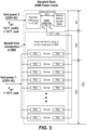
- Fig. 3 shows a rack with a backup battery system (BBS), according to an embodiment of the invention.
- Grid Power 1 is shown as a source of AC power to the rack, which in the illustrated embodiment provides power to the power supply units (PSUs) on the left side of the servers in the rack (as seen in both Figs. 1 and 3 ).
- Grid Power 2 is shown as a separate source of AC power to the rack, which in the illustrated embodiment provides power to the rectifier. The rectifier then provides DC power to charge up the battery backup system (BBS) and also provides DC power to the PSUs on the right side of the servers in the rack.
- BBS battery backup system
- the illustrated PSUs may be capable of operating on either AC or DC power, which allows the rectifier and BBS to be retrofitted into an existing rack without replacing the PSUs.
- other embodiments may replace some AC-only PSUs with DC-only or AC/DC PSUs.
- Fig. 3 appears to show the rectifier and BBS at the top of the rack. However, other embodiments may place the rectifier and/or BBS in any convenient location. Fig. 3 also shows the rectifier and BBS taking up 4 units of rack space, leaving 16 units of rack space for additional servers and their respective PSUs beyond the quantities shown in Fig. 1 . However, other embodiments may use other numbers of units for these purposes. For clarity, Fig. 3 shows only one additional server in this space, but other embodiments may have more.
- BBS may provide output power P B when such power is called upon by a power control module.
- Grid power 1 and Grid power 2 may each provide one-half of the rack power needed, as was the case for Fig. 1 , with the difference in Fig. 3 being that Grid Power 2 goes through a high-efficiency rectifier first.
- the BBS may provide some or all of the additional power needed rather than relying on grid sources for the extra power.
- Fig. 4 shows a flow diagram of a method of controlling total rack input power, according to an embodiment of the invention.
- the operations of flow diagram 400 may be performed by a control unit comprised of one or more processors, monitoring logic, control logic, software, firmware, and/or other modules. Due to the variety of modules and their configurations that may be used to perform these functions, and their distribution through the system, they are not shown in Fig. 4 .
- the control module may be within the rectifier, external to the rectifier, or partly within and partly external to the rectifier.
- the process starts at 405, and at initial state 410 the grid sources P gp1 and P gp2 each provide approximately 1 ⁇ 2 of the total rack power P _rack .
- the control unit determines that the load on the rack has risen and now exceeds the rack power limit P rack_limit by an amount defined here as 2P (i.e., twice the value of P).
- P rack_limit would be 8.8 kW.
- the power level from P gp2 may be reset to 1 ⁇ 2 P rack_limit
- the system may contain a monitoring module (either internal or external to the rectifier) to monitor the output P B of the BBS and set the rectifier to limit its output power P R to the required level.
- the rectifier may adjust its output power by adjusting its output voltage (e.g., increasing output voltage to increase output power, or decreasing output voltage to decrease output power).
- the BBS may then naturally adjust its own output power to supply the extra power required from downstream servers when P R is reduced.
- the output P B of the BBS is set to P (1/2 the amount that the power demand exceeds P rack_limit , per operation 415). Accordingly, P gp2 is reset to 1 ⁇ 2 P rack_limit - P, so that the output power of the BBS increases further by P so that P B reaches a value of 2P.
- BBS output power P B is increased again, to 2P this time, and P gp1 is increased to 1 ⁇ 2 P rack_limit + P.
- P gp2 1 ⁇ 2 P rack_limit - P
- P gp1 1 ⁇ 2 P rack_limit + P
- BBS output P 2 2P.
- the servers are getting the power needed to meet peak load demand, while the Grid Power 1 and Grid Power 2 do not exceed their design limitations, even though the rack has more servers than would be feasible in a prior art rack and the servers are drawing peak loads.
- Operations 405 - 435 have described an embodiment in which the total rack power required may transition from below or at P rack_limit to above P rack_limit .
- Operations 440 - 480 describe an embodiment in which the total rack power may fluctuate dynamically between various levels which may be above or below P rack_limit .
- output power P B from the BBS is assumed to be 2P. (Remember, P was defined as 1 ⁇ 2 the amount by which P _rack exceeded P rack_limit ).
- P gp2 may be reset to 1 ⁇ 2 P rack_limit - P - ⁇ .
- P B may be increased to 2P + 2 ⁇ . This may return the flow diagram to 435, where the total power being supplied by P gp1 and P gp2 is P rack_limit , while the servers are receiving P rack_limit , + the new P B (which is now 2P + 2 ⁇ ).
- the flow may return to 410, where grid power is balanced with grid sources P gp1 and P gp2 each providing approximately 1 ⁇ 2 of the total rack power P _rack .
Landscapes
- Engineering & Computer Science (AREA)
- Theoretical Computer Science (AREA)
- Physics & Mathematics (AREA)
- General Engineering & Computer Science (AREA)
- General Physics & Mathematics (AREA)
- Power Engineering (AREA)
- Power Sources (AREA)
Description
- Various embodiments of the invention pertain to battery backup systems for Internet Data Centers (IDC), with a particular emphasis on increasing rack density by managing power control.
- The growth of very large data centers has resulted in so-called 'server farms' which may contain thousands or tens of thousands of servers. To make efficient use of space, the servers are typically arranged in standardized 19" wide racks, each rack housing multiple servers, with many racks in a room or building. The installed base of server racks is already enormous, with hundreds of thousands, or possibly millions of racks in place. Each rack may be limited to a defined peak power because of its power budget set from the IDC level. IDC upgrade progress is far behind that of the servers and racks, so that many of today's racks still have to be deployed in IDCs that were built years ago with the limitations of that era. Utilization of the rack space is typically low because the racks themselves, and the grid power allocated to each rack by the IDC, were designed in a previous era with earlier technology. Further, the servers may require extra power (beyond their long-term steady state value) that lasts for time periods from several minutes to several hours. Covering this need by providing increased grid power to the racks is impractical because of the very large installed base of power sources and racks and other existing infrastructure in an IDC.
- Within a rack, the allocated power may typically be large enough to handle temporary surges in power (above the average power consumption) demanded by the servers in that rack, as long as those surges don't last more than a defined period of time. Exceeding this defined period of time may cause harmful results, such as emergency computer shutdown or even thermal damage. Therefore, the number of servers in the rack may be intentionally kept low to avoid overstressing the power system when extra power is demanded by the servers.
- Battery backup systems (BBS) are typically used to provide an Uninterruptable Power Supply (UPS) function, where the battery is used to provide power only when the main power source is lost (for example, failure of grid power to a building housing a server farm). In such cases, the BBS may be kept fully charged while grid power is available, to maximize the length of time the BBS can subsequently survive a grid outage. However, the BBS typically does not supplement the grid power when the grid power is available.
- Document
US 20170097667 discloses techniques to enable power manipulation within a data center based on limits for power consumption, power generation, and other criteria. - Document
US 20110304211 discloses a rack power unit configured to be inserted into a device rack of a data center. - Document
US 20140310537 discloses a method that budgets power allocation for an information handling system (HIS). - Document
US 9377832 - Some embodiments of the invention may be better understood by referring to the following description and accompanying drawings that are used to illustrate embodiments of the invention. In the drawings:
-
Fig. 1 shows an embodiment of a prior art server rack. -
Fig. 2 shows a chart of exemplary power consumption in the rack ofFig.1 , according to an embodiment. -
Fig. 3 shows a rack with a backup battery system (BBS), according to an embodiment of the invention. -
Figs. 4A and4B show a flow diagram of a method of controlling total rack input power, according to an embodiment of the invention. - In the following description, numerous specific details are set forth. However, it is understood that embodiments of the invention may be practiced without these specific details. In other instances, well-known circuits, structures and techniques have not been shown in detail in order not to obscure an understanding of this description.
- References to "one embodiment", "an embodiment", "example embodiment", "various embodiments", etc., indicate that the embodiment(s) of the invention so described may include particular features, structures, or characteristics, but not every embodiment necessarily includes the particular features, structures, or characteristics. Further, some embodiments may have some, all, or none of the features described for other embodiments.
- In the following description and claims, the terms "coupled" and "connected," along with their derivatives, may be used. It should be understood that these terms are not intended as synonyms for each other. Rather, in particular embodiments, "connected" is used to indicate that two or more elements are in direct physical or electrical contact with each other. "Coupled" is used to indicate that two or more elements co-operate or interact with each other, but they may or may not have intervening physical or electrical components between them.
- As used in the claims, unless otherwise specified the use of the ordinal adjectives "first", "second", "third", etc., to describe a common element, merely indicate that different instances of like elements are being referred to, and are not intended to imply that the elements so described must be in a given sequence, either temporally, spatially, in ranking, or in any other manner.
- Various embodiments of the invention may be implemented fully or partially in software and/or firmware. This software and/or firmware may take the form of instructions contained in or on a non-transitory computer-readable storage medium. The instructions may be read and executed by the one or more processors to enable performance of the operations described herein. The instructions may be in any suitable form, such as but not limited to source code, compiled code, interpreted code, executable code, static code, dynamic code, and the like. Such a computer-readable medium may include any tangible non-transitory medium for storing information in a form readable by one or more computers, such as but not limited to read only memory (ROM), random access memory (RAM), magnetic disk storage media, optical storage media, a flash memory, etc.
- For reference,
Fig. 1 shows a typical prior art server rack. Although considered prior art, it is shown in this Detailed Description section because it forms the basis for the various embodiments of the invention that are subsequently described. The illustrated rack is shown with a 19 inch horizontal dimension, which has been common in the computer world for decades, but other dimensions may be used. The rack is also shown with a total of 50 units of vertical mounting space in which to mount the servers, but other vertical dimensions may be used. For redundancy, each server is shown with two power supply units (PSU), with each PSU being energized from a separate grid power source (source 1 or source 2). This permits a server to continue operating in the event that one of the PSUs, or the grid power source that powers it, should fail. In a typical configuration, each PSU can supply the server with sufficient power to operate when the other PSU fails. But without such failures, each PSU may supply approximately half the power needed by the server, and the server or PSUs may contain circuitry to balance the load in this manner. - The rack of
Fig. 1 only contains 60% as many servers as the rack has space for, which has been a typical configuration in prior art server farms. The reason for this significant waste of space may be seen inFig. 2 . -
Fig. 2 shows a chart of exemplary power consumption in the rack ofFig. 1 , according to an embodiment. The particular rack of this example has a maximum power rating of 8.8 kilowatts (kW), with a short term power rating (e.g., less than 5 minutes) of 8.0 kW, and a long term power rating (e.g., longer than 5 minutes and even up to a few hours) of 7.2 kW. The steady state power consumption is shown at around 6.5 kW. Considering the possible tolerance of consumed power from each component in the servers and rack,(e.g., CPU, DDR, HDD, etc.), there may not be an easy way to prevent short term peak demands from exceeding their expected range. Therefore a buffer band of 0.8 kW is shown in this example to keep short term peak demands from inadvertently exceeding the maximum power rating of the rack. This may limit the practical peak power of the rack in this example to 8.0 kW. - In the example shown, short term peak load by the servers may add approximately 1.5 kW to the steady-state demand on the PSUs. Similarly, long term peak load by the servers may add approximately 0.7 kW to the steady-state demand on the PSUs. These two factors, combined with the 0.8 kW buffer band, result in a maximum of only 6.5 kW stead state power consumption for all servers in the rack, even though the rack itself may be rated at 8.8 kW. This also indicates how short term peak power may be a key factor in limiting deployment of more servers in a rack. Thus, the number of servers in the rack may be significantly limited to much less than the physical space available for those servers.
-
Fig. 3 shows a rack with a backup battery system (BBS), according to an embodiment of the invention.Grid Power 1 is shown as a source of AC power to the rack, which in the illustrated embodiment provides power to the power supply units (PSUs) on the left side of the servers in the rack (as seen in bothFigs. 1 and3 ). Similarly,Grid Power 2 is shown as a separate source of AC power to the rack, which in the illustrated embodiment provides power to the rectifier. The rectifier then provides DC power to charge up the battery backup system (BBS) and also provides DC power to the PSUs on the right side of the servers in the rack. The illustrated PSUs may be capable of operating on either AC or DC power, which allows the rectifier and BBS to be retrofitted into an existing rack without replacing the PSUs. However, other embodiments may replace some AC-only PSUs with DC-only or AC/DC PSUs. -
Fig. 3 appears to show the rectifier and BBS at the top of the rack. However, other embodiments may place the rectifier and/or BBS in any convenient location.Fig. 3 also shows the rectifier and BBS taking up 4 units of rack space, leaving 16 units of rack space for additional servers and their respective PSUs beyond the quantities shown inFig. 1 . However, other embodiments may use other numbers of units for these purposes. For clarity,Fig. 3 shows only one additional server in this space, but other embodiments may have more. - For the subsequent descriptions of
Figs. 3 and4 , the following definitions may be used: - Pgp1 - The actual power provided by
Grid Power 1. - Pgp2 - The actual power provided by
Grid Power 2. - PR - The output power of the rectifier.
- PB - The output power of the BBS.
- P_rack - Total input power consumed by the rack (as measured from outside the rack), including Pgp1 + Pgp2.
- Prack_limit - Predetermined maximum input power limit set for the rack without considering the BBS output PB , i.e., the maximum permitted for Pgp1 + Pgp2 .
- P - ½ of the amount by which the power consumed by the rack (P_rack) exceeds Prack_limit
- In some embodiments, each server will automatically balance the amount of power being drawn by its two PSUs (assuming a failure of a PSU or its power source does not prevent such balancing). Therefore, assuming no failure, Pgp1 = ½ P_rack . Similarly, PR = ½ P_rack under normal operating conditions when the BBS is not contributing power. If the rectifier has 100% efficiency, then Pgp2 would also be = ½ P_rack . Since the efficiency u of the rectifier may be slightly less (in this case 98%), Pgp2 may be slightly greater than PR. But for simplicity of explanation, the subsequent descriptions may assume PR = Pgp2 . A person of ordinary skill in the art should be able to calculate how much the efficiency of the rectifier affects the descriptions that follow in this document.
- In addition to the power amounts just described, BBS may provide output power PB when such power is called upon by a power control module. Under normal steady state power conditions,
Grid power 1 andGrid power 2 may each provide one-half of the rack power needed, as was the case forFig. 1 , with the difference inFig. 3 being thatGrid Power 2 goes through a high-efficiency rectifier first. However, when the servers need additional power for short or long term peak loads, the BBS may provide some or all of the additional power needed rather than relying on grid sources for the extra power. -
Fig. 4 shows a flow diagram of a method of controlling total rack input power, according to an embodiment of the invention. The operations of flow diagram 400 may be performed by a control unit comprised of one or more processors, monitoring logic, control logic, software, firmware, and/or other modules. Due to the variety of modules and their configurations that may be used to perform these functions, and their distribution through the system, they are not shown inFig. 4 . However, in various embodiment the control module may be within the rectifier, external to the rectifier, or partly within and partly external to the rectifier. - The process starts at 405, and at
initial state 410 the grid sources Pgp1 and Pgp2 each provide approximately ½ of the total rack power P_rack. At 415, the control unit determines that the load on the rack has risen and now exceeds the rack power limit Prack_limit by an amount defined here as 2P (i.e., twice the value of P). When compared to the graph ofFig. 2 , Prack_limit would be 8.8 kW. As a result of the determination at 415, when Pgp2 starts exceeding ½ Prack_limit, at 420 the power level from Pgp2 may be reset to ½ Prack_limit - In one embodiment, the system may contain a monitoring module (either internal or external to the rectifier) to monitor the output PB of the BBS and set the rectifier to limit its output power PR to the required level. In some embodiments, the rectifier may adjust its output power by adjusting its output voltage (e.g., increasing output voltage to increase output power, or decreasing output voltage to decrease output power). The BBS may then naturally adjust its own output power to supply the extra power required from downstream servers when PR is reduced.
- At 425, the output PB of the BBS is set to P (1/2 the amount that the power demand exceeds Prack_limit, per operation 415). Accordingly, Pgp2 is reset to ½ Prack_limit - P, so that the output power of the BBS increases further by P so that PB reaches a value of 2P.
- At 430, BBS output power PB is increased again, to 2P this time, and Pgp1 is increased to ½ Prack_limit + P. At this point, Pgp2 = ½ Prack_limit - P, Pgp1 = ½ Prack_limit + P, and BBS output P2 = 2P. Adding these together, the total power being supplied to the rack by Pgp1 and Pgp2 is Prack_limit, as seen at 435, while the power being supplied to the servers = Prack_limit + 2P. Thus the servers are getting the power needed to meet peak load demand, while the
Grid Power 1 andGrid Power 2 do not exceed their design limitations, even though the rack has more servers than would be feasible in a prior art rack and the servers are drawing peak loads. - Operations 405 - 435 have described an embodiment in which the total rack power required may transition from below or at Prack_limit to above Prack_limit. Operations 440 - 480 describe an embodiment in which the total rack power may fluctuate dynamically between various levels which may be above or below Prack_limit.
- As flow diagram 400 moves from
operation 435 tooperation 440, output power PB from the BBS is assumed to be 2P. (Remember, P was defined as ½ the amount by which P_rack exceeded Prack_limit). At 440, the control unit may monitor the BBS output power PB in real time. If PB increases, as determined at 445, then then the amount of the increase may be defined as a first quantity β, leaving PB = 2P + β at 450. To offset the similar increase from Pgp1, at 455 Pgp2 may be reset to ½ Prack_limit - P - β. Then to offsetoperation 455, at 460 PB may be increased to 2P + 2β. This may return the flow diagram to 435, where the total power being supplied by Pgp1 and Pgp2 is Prack_limit, while the servers are receiving Prack_limit, + the new PB (which is now 2P + 2β). - The previous paragraph describes what may happen if an increase in BBS output is detected at 445. But if such an increase is not detected, flow may proceed to 465, where PB may be decreased by a second quantity α, leaving PB = 2P - α. At 470 it may be determined if 2(P - α ) > 0. If so, at 475 Pgp2 may be reset to ½ Prack_limit - P + α. Then BBU output power PB may be decreased to 2P - 2α at 480 and flow may return to 435. At this point, total rack power P_rack may = Pgp1 and Pgp2 = Prack_limit.. On the other hand, if 2(P - α ) is not > 0, the flow may return to 410, where grid power is balanced with grid sources Pgp1 and Pgp2 each providing approximately ½ of the total rack power P_rack.
Claims (11)
- A computer server rack, the computer server rack having a control unit, a first grid power source, a second grid power source, and a battery backup system, BBS, wherein the computer server rack further comprises a first power supply unit and a second power supply unit in each of multiple servers in the rack, each of said first power supply units is coupled to the first grid power source and each of said second power supply units is coupled to the BBS and to the second grid power source, and wherein each server of the multiple servers in the rack is configured to balance a power demand from the first power supply unit and a power demand from the second power supply unit, the control unit adapted to:detect (415) that a power demand by the multiple servers in the rack exceeds a specified maximum power limit for the rack by twice a first determined amount;set (425) a BBS output power to the first determined amount;set (425) an output power from the second grid power source to one half the maximum power limit minus the first determined amount; andset (430) the BBS output power to twice the first determined amount and set an output from the first grid power source to one half the maximum power limit plus the first determined amount.
- The control unit of claim 1, further adapted to:increase the BBS output power by a second determined amount in response to an increased power demand by the multiple servers;set the second grid power output to said one half the maximum power limit minus the first determined amount minus the second determined amount, in response to said increased power demand; andreset the BBS output power to twice the first determined amount plus twice the second determined amount.
- The control unit of claim 1, further adapted to:decrease the BBS output power by a third determined amount in response to a decreased power demand by the multiple servers;set the first grid power output equal to the second grid power output equal to one half the total rack power, in response to determining that twice the first determined amount minus twice the third determined amount is not greater than zero;set the second grid power output to said one half the maximum power limit minus the first determined amount plus the third determined amount, in response to determining that twice the first determined amount minus twice the third determined amount is greater than zero; andreset the BBS output power to said twice the first determined amount minus twice the third determined amount.
- The control unit of claim 1, wherein the computer server rack further comprises a rectifier coupled between the second grid power source and the BBS.
- The control unit of claim 4, wherein the control unit is to monitor an output of the BBS and is to control an output of the rectifier.
- A method of controlling power in a computer server rack the computer server rack having a first grid power source, a second grid power source, and a battery backup system, BBS, wherein the computer server rack further comprises a first power supply unit and a second power supply unit in each of multiple servers in the rack, each of said first power supply units is coupled to the first grid power source and each of said second power supply units is coupled to the BBS and to the second grid power source, comprising:detecting (415) that a power demand by the multiple servers in the rack exceeds a specified maximum power limit for the rack by twice a first determined amount;setting (425) an output power of the BBS to the first determined amount;setting (425) an output power from the second grid power source to one half the maximum power limit minus the first determined amount; andsetting (430) the output power of the BBS to twice the first determined amount and setting an output power from the first grid power source to one half the maximum power limit plus the first determined amount; andbalancing a power demand from the first power supply unit and a power demand from the second power supply unit within each server of the multiple servers in the computer server rack.
- The method of claim 6, further comprising:increasing the output power of the BBS by a second determined amount in response to an increased power demand by the multiple servers;setting the second grid power output to said one half the maximum power limit minus the first determined amount minus the second determined amount, in response to said increasing the power demand; andresetting the output power of the BBS to twice the first determined amount plus twice the second determined amount.
- The method of claim 6, further comprising:decreasing the output power of the BBS by a third determined amount in response to a decreased power demand by the multiple servers;setting the first grid power output equal to the second grid power output equal to one half the total rack power, in response to determining that twice the first determined amount minus twice the third determined amount is not greater than zero;setting the second grid power output to said one half the maximum power limit minus the first determined amount plus the third determined amount, in response to determining that twice the first determined amount minus twice the third determined amount is greater than zero; andresetting the output power of the BBS to said twice the first determined amount minus twice the third determined amount.
- The method of claim 6, further comprising monitoring the output power of the BBS.
- The method of claim 6, further comprising controlling an output of a rectifier coupled to the BBS.
- A computer-readable non-transitory storage medium that contains instructions, which when executed by the control unit of the computer server rack of any of claims 1 to 5 result in performing the operations of any of method claims 6 to 10.
Applications Claiming Priority (1)
| Application Number | Priority Date | Filing Date | Title |
|---|---|---|---|
| PCT/CN2017/094941 WO2019019163A1 (en) | 2017-07-28 | 2017-07-28 | Smart battery backup system to increase rack density of idc |
Publications (3)
| Publication Number | Publication Date |
|---|---|
| EP3659009A1 EP3659009A1 (en) | 2020-06-03 |
| EP3659009A4 EP3659009A4 (en) | 2021-03-03 |
| EP3659009B1 true EP3659009B1 (en) | 2023-04-05 |
Family
ID=65039433
Family Applications (1)
| Application Number | Title | Priority Date | Filing Date |
|---|---|---|---|
| EP17919225.7A Active EP3659009B1 (en) | 2017-07-28 | 2017-07-28 | Smart battery backup system to increase rack density of idc |
Country Status (3)
| Country | Link |
|---|---|
| EP (1) | EP3659009B1 (en) |
| CN (1) | CN111108460B (en) |
| WO (1) | WO2019019163A1 (en) |
Cited By (1)
| Publication number | Priority date | Publication date | Assignee | Title |
|---|---|---|---|---|
| EP4557050A1 (en) * | 2023-11-17 | 2025-05-21 | Wiwynn Corporation | Server system and power management method thereof |
Families Citing this family (2)
| Publication number | Priority date | Publication date | Assignee | Title |
|---|---|---|---|---|
| DE112018007653T5 (en) | 2018-07-20 | 2021-03-18 | Intel Corporation | Limiting computer rack input power due to failure of the power supply unit |
| WO2022133643A1 (en) * | 2020-12-21 | 2022-06-30 | Intel Corporation | Peak power shaving with multiple batteries, and control mechanism for hybrid energy sources |
Family Cites Families (15)
| Publication number | Priority date | Publication date | Assignee | Title |
|---|---|---|---|---|
| US8723362B2 (en) * | 2009-07-24 | 2014-05-13 | Facebook, Inc. | Direct tie-in of a backup power source to motherboards in a server system |
| US8384244B2 (en) * | 2010-06-09 | 2013-02-26 | Microsoft Corporation | Rack-based uninterruptible power supply |
| CN102360243A (en) * | 2011-10-21 | 2012-02-22 | 百度在线网络技术(北京)有限公司 | Complete machine cabinet and power supply backup method for same |
| US9923413B2 (en) * | 2011-11-11 | 2018-03-20 | Schneider Electric It Corporation | Line balancing UPS |
| US9141164B2 (en) * | 2012-02-01 | 2015-09-22 | Dell Products L.P. | Systems and methods for providing scalable uninterruptable DC power to a rack-level power infrastructure |
| US9377832B1 (en) * | 2013-03-15 | 2016-06-28 | Twitter, Inc. | Data center in a rack |
| US9632552B2 (en) * | 2013-04-10 | 2017-04-25 | Dell Products L.P. | System and method for aggressively budgeting power allocation for an information handling system using redundant configuration of power supply units |
| US10747289B2 (en) * | 2013-10-28 | 2020-08-18 | Virtual Power Systems, Inc. | Data center power manipulation |
| US9552031B2 (en) * | 2013-12-20 | 2017-01-24 | Facebook, Inc. | Power shelf for computer servers |
| CN106575868A (en) * | 2014-03-06 | 2017-04-19 | 罗伯特·博世有限公司 | DC power server for a DC microgrid |
| TWI606330B (en) * | 2014-05-14 | 2017-11-21 | 廣達電腦股份有限公司 | Server system and power switching method thereof |
| US10103574B2 (en) * | 2014-06-21 | 2018-10-16 | Microsoft Technology Licensing, Llc | Controlled concurrent utilization of multiple power supplies |
| CN106664026B (en) * | 2014-09-25 | 2019-11-15 | 英特尔公司 | Power supply units for different power modes |
| CN104917286A (en) * | 2015-06-09 | 2015-09-16 | 浪潮电子信息产业股份有限公司 | A high-reliability whole cabinet continuous power supply device and method |
| US10386421B2 (en) * | 2015-09-14 | 2019-08-20 | Facebook, Inc. | Energy based battery backup unit testing |
-
2017
- 2017-07-28 EP EP17919225.7A patent/EP3659009B1/en active Active
- 2017-07-28 CN CN201780095389.4A patent/CN111108460B/en active Active
- 2017-07-28 WO PCT/CN2017/094941 patent/WO2019019163A1/en not_active Ceased
Cited By (1)
| Publication number | Priority date | Publication date | Assignee | Title |
|---|---|---|---|---|
| EP4557050A1 (en) * | 2023-11-17 | 2025-05-21 | Wiwynn Corporation | Server system and power management method thereof |
Also Published As
| Publication number | Publication date |
|---|---|
| EP3659009A4 (en) | 2021-03-03 |
| EP3659009A1 (en) | 2020-06-03 |
| CN111108460B (en) | 2025-10-17 |
| CN111108460A (en) | 2020-05-05 |
| WO2019019163A1 (en) | 2019-01-31 |
Similar Documents
| Publication | Publication Date | Title |
|---|---|---|
| US11146099B2 (en) | Two-tier battery solution for data center backup | |
| US8261102B2 (en) | Power management system capable of saving power and optimizing operating efficiency of power supplies for providing power with back-up or redundancy to plural loads | |
| US10103574B2 (en) | Controlled concurrent utilization of multiple power supplies | |
| US8390148B2 (en) | Systems and methods for power supply wear leveling in a blade server chassis | |
| US11334135B1 (en) | Power supply optimization using backup battery power supplementation | |
| US9874919B2 (en) | Soft switching control after power interruption | |
| US8193662B1 (en) | Power supply source blending and smoothing | |
| US8129947B2 (en) | Method and system for utilizing a memory control circuit for controlling data transfer to and from a memory system | |
| US10664030B2 (en) | System and method for dynamic power capping and load balance management for a multi-node system | |
| US8736107B1 (en) | Power source redundancy in a power supply | |
| US8671295B2 (en) | Generating a signal to reduce computer system power consumption from signals provided by a plurality of power supplies | |
| US20210048867A1 (en) | Systems and methods for optimizing fault tolerant redundancy for an information handling system with multiple power supply units | |
| WO2015088569A1 (en) | Powering loads with a power supply and an uninterruptible power supply | |
| US20230185350A1 (en) | Data center electrical power distribution with modular mechanical cooling isolation | |
| CN111108460B (en) | Intelligent battery backup system for increasing rack density of IDCs | |
| US20200394081A1 (en) | Leveraging reserved data center resources to improve data center utilization | |
| US11320884B2 (en) | Limiting computing rack input power due to power supply unit failure | |
| US20190146565A1 (en) | Data center fuel cells | |
| US20200105312A1 (en) | NVDIMM System with UPS power source | |
| US11977900B2 (en) | Dynamic timing for shutdown including asynchronous dynamic random access memory refresh (ADR) due to AC undervoltage | |
| EP4715523A1 (en) | Mitigating power fluctuations using battery energy storage systems | |
| US11050294B1 (en) | Power supply shedding for power efficiency optimization | |
| US20140067149A1 (en) | Computing device and method for dynamically regulating solar power | |
| US9991703B1 (en) | Dual wall input for network attached storage device | |
| US10298055B1 (en) | Power supply with programmable restriction |
Legal Events
| Date | Code | Title | Description |
|---|---|---|---|
| STAA | Information on the status of an ep patent application or granted ep patent |
Free format text: STATUS: THE INTERNATIONAL PUBLICATION HAS BEEN MADE |
|
| PUAI | Public reference made under article 153(3) epc to a published international application that has entered the european phase |
Free format text: ORIGINAL CODE: 0009012 |
|
| STAA | Information on the status of an ep patent application or granted ep patent |
Free format text: STATUS: REQUEST FOR EXAMINATION WAS MADE |
|
| 17P | Request for examination filed |
Effective date: 20191211 |
|
| AK | Designated contracting states |
Kind code of ref document: A1 Designated state(s): AL AT BE BG CH CY CZ DE DK EE ES FI FR GB GR HR HU IE IS IT LI LT LU LV MC MK MT NL NO PL PT RO RS SE SI SK SM TR |
|
| AX | Request for extension of the european patent |
Extension state: BA ME |
|
| DAV | Request for validation of the european patent (deleted) | ||
| DAX | Request for extension of the european patent (deleted) | ||
| A4 | Supplementary search report drawn up and despatched |
Effective date: 20210129 |
|
| RIC1 | Information provided on ipc code assigned before grant |
Ipc: G06F 1/26 20060101AFI20210125BHEP |
|
| STAA | Information on the status of an ep patent application or granted ep patent |
Free format text: STATUS: EXAMINATION IS IN PROGRESS |
|
| 17Q | First examination report despatched |
Effective date: 20220421 |
|
| GRAP | Despatch of communication of intention to grant a patent |
Free format text: ORIGINAL CODE: EPIDOSNIGR1 |
|
| STAA | Information on the status of an ep patent application or granted ep patent |
Free format text: STATUS: GRANT OF PATENT IS INTENDED |
|
| INTG | Intention to grant announced |
Effective date: 20221024 |
|
| RIN1 | Information on inventor provided before grant (corrected) |
Inventor name: HUO, SIXIAO Inventor name: UAN-ZO-LI, ALEXANDER B. Inventor name: SHU, WENHUI Inventor name: ZHOU, XIANG Inventor name: LIANG, XIAOGUO Inventor name: SONG, CHUAN |
|
| GRAS | Grant fee paid |
Free format text: ORIGINAL CODE: EPIDOSNIGR3 |
|
| GRAA | (expected) grant |
Free format text: ORIGINAL CODE: 0009210 |
|
| STAA | Information on the status of an ep patent application or granted ep patent |
Free format text: STATUS: THE PATENT HAS BEEN GRANTED |
|
| AK | Designated contracting states |
Kind code of ref document: B1 Designated state(s): AL AT BE BG CH CY CZ DE DK EE ES FI FR GB GR HR HU IE IS IT LI LT LU LV MC MK MT NL NO PL PT RO RS SE SI SK SM TR |
|
| REG | Reference to a national code |
Ref country code: GB Ref legal event code: FG4D |
|
| REG | Reference to a national code |
Ref country code: CH Ref legal event code: EP |
|
| REG | Reference to a national code |
Ref country code: AT Ref legal event code: REF Ref document number: 1558724 Country of ref document: AT Kind code of ref document: T Effective date: 20230415 |
|
| REG | Reference to a national code |
Ref country code: DE Ref legal event code: R096 Ref document number: 602017067586 Country of ref document: DE |
|
| REG | Reference to a national code |
Ref country code: IE Ref legal event code: FG4D |
|
| REG | Reference to a national code |
Ref country code: NL Ref legal event code: FP |
|
| P01 | Opt-out of the competence of the unified patent court (upc) registered |
Effective date: 20230530 |
|
| REG | Reference to a national code |
Ref country code: LT Ref legal event code: MG9D |
|
| REG | Reference to a national code |
Ref country code: AT Ref legal event code: MK05 Ref document number: 1558724 Country of ref document: AT Kind code of ref document: T Effective date: 20230405 |
|
| PG25 | Lapsed in a contracting state [announced via postgrant information from national office to epo] |
Ref country code: SE Free format text: LAPSE BECAUSE OF FAILURE TO SUBMIT A TRANSLATION OF THE DESCRIPTION OR TO PAY THE FEE WITHIN THE PRESCRIBED TIME-LIMIT Effective date: 20230405 Ref country code: PT Free format text: LAPSE BECAUSE OF FAILURE TO SUBMIT A TRANSLATION OF THE DESCRIPTION OR TO PAY THE FEE WITHIN THE PRESCRIBED TIME-LIMIT Effective date: 20230807 Ref country code: NO Free format text: LAPSE BECAUSE OF FAILURE TO SUBMIT A TRANSLATION OF THE DESCRIPTION OR TO PAY THE FEE WITHIN THE PRESCRIBED TIME-LIMIT Effective date: 20230705 Ref country code: ES Free format text: LAPSE BECAUSE OF FAILURE TO SUBMIT A TRANSLATION OF THE DESCRIPTION OR TO PAY THE FEE WITHIN THE PRESCRIBED TIME-LIMIT Effective date: 20230405 Ref country code: AT Free format text: LAPSE BECAUSE OF FAILURE TO SUBMIT A TRANSLATION OF THE DESCRIPTION OR TO PAY THE FEE WITHIN THE PRESCRIBED TIME-LIMIT Effective date: 20230405 |
|
| PG25 | Lapsed in a contracting state [announced via postgrant information from national office to epo] |
Ref country code: RS Free format text: LAPSE BECAUSE OF FAILURE TO SUBMIT A TRANSLATION OF THE DESCRIPTION OR TO PAY THE FEE WITHIN THE PRESCRIBED TIME-LIMIT Effective date: 20230405 Ref country code: PL Free format text: LAPSE BECAUSE OF FAILURE TO SUBMIT A TRANSLATION OF THE DESCRIPTION OR TO PAY THE FEE WITHIN THE PRESCRIBED TIME-LIMIT Effective date: 20230405 Ref country code: LV Free format text: LAPSE BECAUSE OF FAILURE TO SUBMIT A TRANSLATION OF THE DESCRIPTION OR TO PAY THE FEE WITHIN THE PRESCRIBED TIME-LIMIT Effective date: 20230405 Ref country code: LT Free format text: LAPSE BECAUSE OF FAILURE TO SUBMIT A TRANSLATION OF THE DESCRIPTION OR TO PAY THE FEE WITHIN THE PRESCRIBED TIME-LIMIT Effective date: 20230405 Ref country code: IS Free format text: LAPSE BECAUSE OF FAILURE TO SUBMIT A TRANSLATION OF THE DESCRIPTION OR TO PAY THE FEE WITHIN THE PRESCRIBED TIME-LIMIT Effective date: 20230805 Ref country code: HR Free format text: LAPSE BECAUSE OF FAILURE TO SUBMIT A TRANSLATION OF THE DESCRIPTION OR TO PAY THE FEE WITHIN THE PRESCRIBED TIME-LIMIT Effective date: 20230405 Ref country code: GR Free format text: LAPSE BECAUSE OF FAILURE TO SUBMIT A TRANSLATION OF THE DESCRIPTION OR TO PAY THE FEE WITHIN THE PRESCRIBED TIME-LIMIT Effective date: 20230706 |
|
| PG25 | Lapsed in a contracting state [announced via postgrant information from national office to epo] |
Ref country code: FI Free format text: LAPSE BECAUSE OF FAILURE TO SUBMIT A TRANSLATION OF THE DESCRIPTION OR TO PAY THE FEE WITHIN THE PRESCRIBED TIME-LIMIT Effective date: 20230405 |
|
| REG | Reference to a national code |
Ref country code: DE Ref legal event code: R097 Ref document number: 602017067586 Country of ref document: DE |
|
| PG25 | Lapsed in a contracting state [announced via postgrant information from national office to epo] |
Ref country code: SK Free format text: LAPSE BECAUSE OF FAILURE TO SUBMIT A TRANSLATION OF THE DESCRIPTION OR TO PAY THE FEE WITHIN THE PRESCRIBED TIME-LIMIT Effective date: 20230405 |
|
| PG25 | Lapsed in a contracting state [announced via postgrant information from national office to epo] |
Ref country code: SM Free format text: LAPSE BECAUSE OF FAILURE TO SUBMIT A TRANSLATION OF THE DESCRIPTION OR TO PAY THE FEE WITHIN THE PRESCRIBED TIME-LIMIT Effective date: 20230405 Ref country code: SK Free format text: LAPSE BECAUSE OF FAILURE TO SUBMIT A TRANSLATION OF THE DESCRIPTION OR TO PAY THE FEE WITHIN THE PRESCRIBED TIME-LIMIT Effective date: 20230405 Ref country code: RO Free format text: LAPSE BECAUSE OF FAILURE TO SUBMIT A TRANSLATION OF THE DESCRIPTION OR TO PAY THE FEE WITHIN THE PRESCRIBED TIME-LIMIT Effective date: 20230405 Ref country code: EE Free format text: LAPSE BECAUSE OF FAILURE TO SUBMIT A TRANSLATION OF THE DESCRIPTION OR TO PAY THE FEE WITHIN THE PRESCRIBED TIME-LIMIT Effective date: 20230405 Ref country code: DK Free format text: LAPSE BECAUSE OF FAILURE TO SUBMIT A TRANSLATION OF THE DESCRIPTION OR TO PAY THE FEE WITHIN THE PRESCRIBED TIME-LIMIT Effective date: 20230405 Ref country code: CZ Free format text: LAPSE BECAUSE OF FAILURE TO SUBMIT A TRANSLATION OF THE DESCRIPTION OR TO PAY THE FEE WITHIN THE PRESCRIBED TIME-LIMIT Effective date: 20230405 |
|
| PLBE | No opposition filed within time limit |
Free format text: ORIGINAL CODE: 0009261 |
|
| STAA | Information on the status of an ep patent application or granted ep patent |
Free format text: STATUS: NO OPPOSITION FILED WITHIN TIME LIMIT |
|
| PG25 | Lapsed in a contracting state [announced via postgrant information from national office to epo] |
Ref country code: MC Free format text: LAPSE BECAUSE OF FAILURE TO SUBMIT A TRANSLATION OF THE DESCRIPTION OR TO PAY THE FEE WITHIN THE PRESCRIBED TIME-LIMIT Effective date: 20230405 |
|
| PG25 | Lapsed in a contracting state [announced via postgrant information from national office to epo] |
Ref country code: MC Free format text: LAPSE BECAUSE OF FAILURE TO SUBMIT A TRANSLATION OF THE DESCRIPTION OR TO PAY THE FEE WITHIN THE PRESCRIBED TIME-LIMIT Effective date: 20230405 |
|
| REG | Reference to a national code |
Ref country code: CH Ref legal event code: PL |
|
| 26N | No opposition filed |
Effective date: 20240108 |
|
| REG | Reference to a national code |
Ref country code: BE Ref legal event code: MM Effective date: 20230731 |
|
| PG25 | Lapsed in a contracting state [announced via postgrant information from national office to epo] |
Ref country code: LU Free format text: LAPSE BECAUSE OF NON-PAYMENT OF DUE FEES Effective date: 20230728 |
|
| PG25 | Lapsed in a contracting state [announced via postgrant information from national office to epo] |
Ref country code: LU Free format text: LAPSE BECAUSE OF NON-PAYMENT OF DUE FEES Effective date: 20230728 |
|
| REG | Reference to a national code |
Ref country code: IE Ref legal event code: MM4A |
|
| PG25 | Lapsed in a contracting state [announced via postgrant information from national office to epo] |
Ref country code: CH Free format text: LAPSE BECAUSE OF NON-PAYMENT OF DUE FEES Effective date: 20230731 |
|
| PG25 | Lapsed in a contracting state [announced via postgrant information from national office to epo] |
Ref country code: SI Free format text: LAPSE BECAUSE OF FAILURE TO SUBMIT A TRANSLATION OF THE DESCRIPTION OR TO PAY THE FEE WITHIN THE PRESCRIBED TIME-LIMIT Effective date: 20230405 |
|
| PG25 | Lapsed in a contracting state [announced via postgrant information from national office to epo] |
Ref country code: SI Free format text: LAPSE BECAUSE OF FAILURE TO SUBMIT A TRANSLATION OF THE DESCRIPTION OR TO PAY THE FEE WITHIN THE PRESCRIBED TIME-LIMIT Effective date: 20230405 Ref country code: IT Free format text: LAPSE BECAUSE OF FAILURE TO SUBMIT A TRANSLATION OF THE DESCRIPTION OR TO PAY THE FEE WITHIN THE PRESCRIBED TIME-LIMIT Effective date: 20230405 Ref country code: BE Free format text: LAPSE BECAUSE OF NON-PAYMENT OF DUE FEES Effective date: 20230731 |
|
| PG25 | Lapsed in a contracting state [announced via postgrant information from national office to epo] |
Ref country code: IE Free format text: LAPSE BECAUSE OF NON-PAYMENT OF DUE FEES Effective date: 20230728 |
|
| PG25 | Lapsed in a contracting state [announced via postgrant information from national office to epo] |
Ref country code: IE Free format text: LAPSE BECAUSE OF NON-PAYMENT OF DUE FEES Effective date: 20230728 |
|
| PG25 | Lapsed in a contracting state [announced via postgrant information from national office to epo] |
Ref country code: BG Free format text: LAPSE BECAUSE OF FAILURE TO SUBMIT A TRANSLATION OF THE DESCRIPTION OR TO PAY THE FEE WITHIN THE PRESCRIBED TIME-LIMIT Effective date: 20230405 |
|
| PG25 | Lapsed in a contracting state [announced via postgrant information from national office to epo] |
Ref country code: BG Free format text: LAPSE BECAUSE OF FAILURE TO SUBMIT A TRANSLATION OF THE DESCRIPTION OR TO PAY THE FEE WITHIN THE PRESCRIBED TIME-LIMIT Effective date: 20230405 |
|
| PGFP | Annual fee paid to national office [announced via postgrant information from national office to epo] |
Ref country code: GB Payment date: 20250619 Year of fee payment: 9 |
|
| PGFP | Annual fee paid to national office [announced via postgrant information from national office to epo] |
Ref country code: NL Payment date: 20250627 Year of fee payment: 9 |
|
| PGFP | Annual fee paid to national office [announced via postgrant information from national office to epo] |
Ref country code: FR Payment date: 20250623 Year of fee payment: 9 |
|
| PG25 | Lapsed in a contracting state [announced via postgrant information from national office to epo] |
Ref country code: CY Free format text: LAPSE BECAUSE OF FAILURE TO SUBMIT A TRANSLATION OF THE DESCRIPTION OR TO PAY THE FEE WITHIN THE PRESCRIBED TIME-LIMIT; INVALID AB INITIO Effective date: 20170728 |
|
| PG25 | Lapsed in a contracting state [announced via postgrant information from national office to epo] |
Ref country code: HU Free format text: LAPSE BECAUSE OF FAILURE TO SUBMIT A TRANSLATION OF THE DESCRIPTION OR TO PAY THE FEE WITHIN THE PRESCRIBED TIME-LIMIT; INVALID AB INITIO Effective date: 20170728 |
|
| PGFP | Annual fee paid to national office [announced via postgrant information from national office to epo] |
Ref country code: DE Payment date: 20250618 Year of fee payment: 9 |
|
| PG25 | Lapsed in a contracting state [announced via postgrant information from national office to epo] |
Ref country code: TR Free format text: LAPSE BECAUSE OF FAILURE TO SUBMIT A TRANSLATION OF THE DESCRIPTION OR TO PAY THE FEE WITHIN THE PRESCRIBED TIME-LIMIT Effective date: 20230405 |