EP3658793B1 - Fluid cushion guiding device - Google Patents
Fluid cushion guiding device Download PDFInfo
- Publication number
- EP3658793B1 EP3658793B1 EP18750515.1A EP18750515A EP3658793B1 EP 3658793 B1 EP3658793 B1 EP 3658793B1 EP 18750515 A EP18750515 A EP 18750515A EP 3658793 B1 EP3658793 B1 EP 3658793B1
- Authority
- EP
- European Patent Office
- Prior art keywords
- guiding device
- gap
- radial
- shaft
- inner sleeve
- Prior art date
- Legal status (The legal status is an assumption and is not a legal conclusion. Google has not performed a legal analysis and makes no representation as to the accuracy of the status listed.)
- Active
Links
Images


Classifications
-
- F—MECHANICAL ENGINEERING; LIGHTING; HEATING; WEAPONS; BLASTING
- F16—ENGINEERING ELEMENTS AND UNITS; GENERAL MEASURES FOR PRODUCING AND MAINTAINING EFFECTIVE FUNCTIONING OF MACHINES OR INSTALLATIONS; THERMAL INSULATION IN GENERAL
- F16C—SHAFTS; FLEXIBLE SHAFTS; ELEMENTS OR CRANKSHAFT MECHANISMS; ROTARY BODIES OTHER THAN GEARING ELEMENTS; BEARINGS
- F16C32/00—Bearings not otherwise provided for
- F16C32/06—Bearings not otherwise provided for with moving member supported by a fluid cushion formed, at least to a large extent, otherwise than by movement of the shaft, e.g. hydrostatic air-cushion bearings
- F16C32/0603—Bearings not otherwise provided for with moving member supported by a fluid cushion formed, at least to a large extent, otherwise than by movement of the shaft, e.g. hydrostatic air-cushion bearings supported by a gas cushion, e.g. an air cushion
- F16C32/0614—Bearings not otherwise provided for with moving member supported by a fluid cushion formed, at least to a large extent, otherwise than by movement of the shaft, e.g. hydrostatic air-cushion bearings supported by a gas cushion, e.g. an air cushion the gas being supplied under pressure, e.g. aerostatic bearings
- F16C32/0622—Bearings not otherwise provided for with moving member supported by a fluid cushion formed, at least to a large extent, otherwise than by movement of the shaft, e.g. hydrostatic air-cushion bearings supported by a gas cushion, e.g. an air cushion the gas being supplied under pressure, e.g. aerostatic bearings via nozzles, restrictors
-
- F—MECHANICAL ENGINEERING; LIGHTING; HEATING; WEAPONS; BLASTING
- F16—ENGINEERING ELEMENTS AND UNITS; GENERAL MEASURES FOR PRODUCING AND MAINTAINING EFFECTIVE FUNCTIONING OF MACHINES OR INSTALLATIONS; THERMAL INSULATION IN GENERAL
- F16C—SHAFTS; FLEXIBLE SHAFTS; ELEMENTS OR CRANKSHAFT MECHANISMS; ROTARY BODIES OTHER THAN GEARING ELEMENTS; BEARINGS
- F16C31/00—Bearings for parts which both rotate and move linearly
- F16C31/02—Sliding-contact bearings
-
- F—MECHANICAL ENGINEERING; LIGHTING; HEATING; WEAPONS; BLASTING
- F16—ENGINEERING ELEMENTS AND UNITS; GENERAL MEASURES FOR PRODUCING AND MAINTAINING EFFECTIVE FUNCTIONING OF MACHINES OR INSTALLATIONS; THERMAL INSULATION IN GENERAL
- F16C—SHAFTS; FLEXIBLE SHAFTS; ELEMENTS OR CRANKSHAFT MECHANISMS; ROTARY BODIES OTHER THAN GEARING ELEMENTS; BEARINGS
- F16C32/00—Bearings not otherwise provided for
- F16C32/06—Bearings not otherwise provided for with moving member supported by a fluid cushion formed, at least to a large extent, otherwise than by movement of the shaft, e.g. hydrostatic air-cushion bearings
-
- F—MECHANICAL ENGINEERING; LIGHTING; HEATING; WEAPONS; BLASTING
- F16—ENGINEERING ELEMENTS AND UNITS; GENERAL MEASURES FOR PRODUCING AND MAINTAINING EFFECTIVE FUNCTIONING OF MACHINES OR INSTALLATIONS; THERMAL INSULATION IN GENERAL
- F16C—SHAFTS; FLEXIBLE SHAFTS; ELEMENTS OR CRANKSHAFT MECHANISMS; ROTARY BODIES OTHER THAN GEARING ELEMENTS; BEARINGS
- F16C32/00—Bearings not otherwise provided for
- F16C32/06—Bearings not otherwise provided for with moving member supported by a fluid cushion formed, at least to a large extent, otherwise than by movement of the shaft, e.g. hydrostatic air-cushion bearings
- F16C32/0629—Bearings not otherwise provided for with moving member supported by a fluid cushion formed, at least to a large extent, otherwise than by movement of the shaft, e.g. hydrostatic air-cushion bearings supported by a liquid cushion, e.g. oil cushion
- F16C32/064—Bearings not otherwise provided for with moving member supported by a fluid cushion formed, at least to a large extent, otherwise than by movement of the shaft, e.g. hydrostatic air-cushion bearings supported by a liquid cushion, e.g. oil cushion the liquid being supplied under pressure
- F16C32/0651—Details of the bearing area per se
- F16C32/0655—Details of the bearing area per se of supply openings
-
- F—MECHANICAL ENGINEERING; LIGHTING; HEATING; WEAPONS; BLASTING
- F16—ENGINEERING ELEMENTS AND UNITS; GENERAL MEASURES FOR PRODUCING AND MAINTAINING EFFECTIVE FUNCTIONING OF MACHINES OR INSTALLATIONS; THERMAL INSULATION IN GENERAL
- F16C—SHAFTS; FLEXIBLE SHAFTS; ELEMENTS OR CRANKSHAFT MECHANISMS; ROTARY BODIES OTHER THAN GEARING ELEMENTS; BEARINGS
- F16C33/00—Parts of bearings; Special methods for making bearings or parts thereof
- F16C33/02—Parts of sliding-contact bearings
- F16C33/04—Brasses; Bushes; Linings
- F16C33/06—Sliding surface mainly made of metal
- F16C33/10—Construction relative to lubrication
- F16C33/1005—Construction relative to lubrication with gas, e.g. air, as lubricant
-
- F—MECHANICAL ENGINEERING; LIGHTING; HEATING; WEAPONS; BLASTING
- F16—ENGINEERING ELEMENTS AND UNITS; GENERAL MEASURES FOR PRODUCING AND MAINTAINING EFFECTIVE FUNCTIONING OF MACHINES OR INSTALLATIONS; THERMAL INSULATION IN GENERAL
- F16C—SHAFTS; FLEXIBLE SHAFTS; ELEMENTS OR CRANKSHAFT MECHANISMS; ROTARY BODIES OTHER THAN GEARING ELEMENTS; BEARINGS
- F16C41/00—Other accessories, e.g. devices integrated in the bearing not relating to the bearing function as such
-
- F—MECHANICAL ENGINEERING; LIGHTING; HEATING; WEAPONS; BLASTING
- F16—ENGINEERING ELEMENTS AND UNITS; GENERAL MEASURES FOR PRODUCING AND MAINTAINING EFFECTIVE FUNCTIONING OF MACHINES OR INSTALLATIONS; THERMAL INSULATION IN GENERAL
- F16C—SHAFTS; FLEXIBLE SHAFTS; ELEMENTS OR CRANKSHAFT MECHANISMS; ROTARY BODIES OTHER THAN GEARING ELEMENTS; BEARINGS
- F16C32/00—Bearings not otherwise provided for
- F16C32/06—Bearings not otherwise provided for with moving member supported by a fluid cushion formed, at least to a large extent, otherwise than by movement of the shaft, e.g. hydrostatic air-cushion bearings
- F16C32/0603—Bearings not otherwise provided for with moving member supported by a fluid cushion formed, at least to a large extent, otherwise than by movement of the shaft, e.g. hydrostatic air-cushion bearings supported by a gas cushion, e.g. an air cushion
- F16C32/0614—Bearings not otherwise provided for with moving member supported by a fluid cushion formed, at least to a large extent, otherwise than by movement of the shaft, e.g. hydrostatic air-cushion bearings supported by a gas cushion, e.g. an air cushion the gas being supplied under pressure, e.g. aerostatic bearings
- F16C32/0625—Bearings not otherwise provided for with moving member supported by a fluid cushion formed, at least to a large extent, otherwise than by movement of the shaft, e.g. hydrostatic air-cushion bearings supported by a gas cushion, e.g. an air cushion the gas being supplied under pressure, e.g. aerostatic bearings via supply slits
-
- F—MECHANICAL ENGINEERING; LIGHTING; HEATING; WEAPONS; BLASTING
- F16—ENGINEERING ELEMENTS AND UNITS; GENERAL MEASURES FOR PRODUCING AND MAINTAINING EFFECTIVE FUNCTIONING OF MACHINES OR INSTALLATIONS; THERMAL INSULATION IN GENERAL
- F16C—SHAFTS; FLEXIBLE SHAFTS; ELEMENTS OR CRANKSHAFT MECHANISMS; ROTARY BODIES OTHER THAN GEARING ELEMENTS; BEARINGS
- F16C32/00—Bearings not otherwise provided for
- F16C32/06—Bearings not otherwise provided for with moving member supported by a fluid cushion formed, at least to a large extent, otherwise than by movement of the shaft, e.g. hydrostatic air-cushion bearings
- F16C32/0629—Bearings not otherwise provided for with moving member supported by a fluid cushion formed, at least to a large extent, otherwise than by movement of the shaft, e.g. hydrostatic air-cushion bearings supported by a liquid cushion, e.g. oil cushion
- F16C32/064—Bearings not otherwise provided for with moving member supported by a fluid cushion formed, at least to a large extent, otherwise than by movement of the shaft, e.g. hydrostatic air-cushion bearings supported by a liquid cushion, e.g. oil cushion the liquid being supplied under pressure
- F16C32/0644—Details of devices to control the supply of liquids to the bearings
- F16C32/0648—Details of devices to control the supply of liquids to the bearings by sensors or pressure-responsive control devices in or near the bearings
Definitions
- the present invention relates to the devices for guiding a rotary motion and/or a translatory motion of a member.
- the invention concerns a fluid cushion guiding device, in particular an air cushion guiding device.
- Known guiding devices capable of performing such a function, are for example bushings made of a material with low frictional coefficient, in order to facilitate the sliding of the member to be guided and to limit the resulting overheating, or recirculating ball bushings or bushings with a plurality of stationary balls, arranged to allow the relative roto-translation between the same bushings and the members to be guided.
- Such devices require a physical contact with the members to be guided, and this originates a number of problems. These problems concern in particular the alignment of the axes of the guiding devices and the members to be guided, the working tolerances, the need for lubrication between the contacting surfaces of the guiding devices and the members to be guided, and the wear of such surfaces as well as of the balls, if any, of the guiding devices, which balls could creep on the surfaces of the members to be guided.
- EP1208289 B1 discloses a device with features according to the preamble of claim 1.
- the guiding device comprises an inner cylindrical portion and an outer cylindrical portion, which are coaxial with each other and are configured so as to allow creating a gap (or cushion) of pressurised fluid between the inner cylindrical portion and a member to be guided in a relative rotary and/or translatory movement relative to the guiding device
- the inner cylindrical portion has plurality of radial holes, preferably through holes, having first ends communicating, preferably directly, with a first gap formed between the inner cylindrical portion and a member to be guided.
- the outer cylindrical portion has at least one radial opening arranged to allow introducing a pressurised fluid from the outside, which fluid reaches the first gap through the radial holes and creates the fluidic gap between the inner cylindrical portion and the member to be guided.
- the radial holes of the inner cylindrical portion preferably have end portions directed towards the respective first ends and having a cross-section larger than the remaining cross-section of the holes.
- the end portions have a frusto-conical shape with cross-sectional size progressively increasing towards the first ends of the respective holes.
- a balance condition defined as the condition in which the fluidic gap has uniform thickness
- fluid volumes with uniform pressure are advantageously created at said end portions.
- the pressure of the fluid present in a given end portion changes in inverse proportion to the thickness of the fluidic gap at said end portion.
- the fluidic gap formed between the inner cylindrical portion and the member to be guided takes a non-uniform thickness and decreases on one side of the guiding device and increases on the radially opposite side
- the pressure of the fluid volumes in the end portions increases where the thickness of the fluidic gap is smaller and decreases where the thickness is greater. This creates a pressure difference pushing the member to be guided towards the side where the fluidic gap has a greater thickness, thereby tending to restore the balance condition in which the thickness of the fluidic gap is uniform.
- the guiding device includes a second gap formed between the inner cylindrical portion and the outer cylindrical portion and communicating, preferably directly, with the at least one radial opening of the outer cylindrical portion.
- the radial holes of the inner cylindrical portion have second ends communicating, preferably directly, with such a second gap, so that the fluid introduced into the at least one radial opening reaches the first gap through the second gap and the radial holes in order to form the fluidic gap.
- no gap is formed between the inner cylindrical portion and the outer cylindrical portion.
- the inner cylindrical portion includes instead a network of channels establishing communication between the radial holes of the same portion, and the at least one radial opening of the outer cylindrical portion communicates, preferably directly, with a respective radial hole aligned with the same opening.
- the fluid introduced into the at least one radial opening reaches the first gap through the network of communication channels and the radial holes in order to form the fluidic gap.
- the guiding device includes both the second gap and the network of communication channels.
- the outer cylindrical portion includes at least two radial openings
- the second gap between the inner cylindrical portion and the outer cylindrical portion is divided into at least two sectors or segments that are not in direct communication with each other.
- Each sector of the gap communicates, preferably directly, with a corresponding radial opening of the outer cylindrical portion and with second ends of a corresponding subset of radial holes of the inner cylindrical portion.
- no gap is formed between the inner cylindrical portion and the outer cylindrical portion.
- the inner cylindrical portion includes instead at least two networks of channels establishing communication between radial holes, the networks not being in direct communication with each other.
- the outer cylindrical portion comprises at least two radial openings and each network of channels communicates with a corresponding radial opening and is arranged to make the radial holes of a corresponding subset of radial holes of the inner cylindrical portion communicate with one another. Thanks to such a configuration, by introducing pressurised fluid through one or more radial openings, it is possible to increase the pressure in the only subsets of holes associated with such radial openings. For instance, this advantageously allows increasing the pressure in the only radial holes where the fluidic gap has taken a smaller thickness, in order to more quickly restore the balance condition in which the thickness of the fluidic gap is uniform.
- the inner cylindrical portion and the outer cylindrical portion of the guiding device are two separate sleeves, i.e. an inner sleeve and an outer sleeve.
- the two cylindrical portions can be made as an integral piece by means of the 3D printing technology (Additive Manufacturing).
- the guiding device includes sensors capable of detecting the relative displacements between the guiding device and the member to be guided, more particularly a possible misalignment between the axis of the guiding device and the axis of the member to be guided, and a control system configured to control introduction of the pressurised fluid through one or more radial openings of the outer cylindrical portion based on the displacements detected by the sensors.
- the control system controls fluid introduction through one or more radial openings located on the side of the guiding device where the thickness of the fluidic gap is smaller, or anyway openings communicating with subsets of radial holes where the thickness of the fluidic gap is smaller. This allows compensating more quickly the misalignment of the member to be guided relative to the aforesaid balance condition.
- the invention also provides a capping head for applying for instance screw or pressure caps to containers, wherein a cap application part has a shaft that can be driven according to a rotary movement about a longitudinal axis and a translatory movement along said axis.
- the capping head includes a guiding device according to the invention arranged to guide the shaft in its rotary and/or translatory movement.
- Device 1 is a bushing comprising two coaxial cylindrical sleeves, i.e. an inner sleeve 10 and an outer sleeve 11, preferably but not necessarily having the same length.
- the Figures also show a member, for instance a shaft 2, arranged to be guided by device 1. More particularly, guiding device 1 is arranged to drive a shaft 2 into a rotary, translatory or roto-translatory movement relative to guiding device 1. Thus, it is possible, for instance, to apply a roto-translatory movement to either shaft 2 or guiding device 1, or to apply one of the rotary or translatory movements to shaft 2 and to apply the other movement to guiding device 1.
- Reference symbol A denotes the longitudinal axis of both sleeves.
- Inner sleeve 10 of guiding device 1 has a plurality of radial through holes 12. Such holes 12 have first ends 13 in communication with a first gap 15 formed between inner sleeve 10 and shaft 2, and second ends 14 communicating, preferably directly, with a second gap 16 formed between inner sleeve 10 and outer sleeve 11.
- inner sleeve 10 further includes a plurality of channels (not shown in the Figures) establishing communication among the holes.
- Outer sleeve 11 of guiding device 1 has at least one radial opening 17 communicating, preferably directly, with the second gap 16 and arranged to allow introduction of a pressurised fluid, e.g. air, from the outside. Such a fluid reaches the first gap 15 through the second gap 16 and the plurality of radial holes 12.
- a pressurised fluid e.g. air
- the presence of pressurised fluid in the first gap 15 advantageously allows creating a fluidic gap (or cushion) in the first gap 15, between inner sleeve 10 and shaft 2. Thanks to such a fluidic gap, inner sleeve 10 and shaft 2 are prevented from coming into contact, both in static conditions and in conditions of relative rotary and/or translatory motion between the sleeve and the shaft. In this way, wear due to friction between guiding device 1 and shaft 2 is advantageously avoided. More particularly, a balance condition is defined in which longitudinal axis A of the inner and outer sleeves coincides with the shaft axis. In such a balance condition, the fluidic gap has uniform thickness.
- radial holes 12 are preferably uniformly distributed in inner sleeve 10 so as to ensure a uniform distribution of the fluid in the first gap 15 in the balance condition defined above.
- guiding device 1 includes sealing elements with low frictional coefficient (not shown in the Figures) associated with inner sleeve 10 and arranged to cooperate with shaft 2.
- sealing elements allow limiting fluid leakage from the first gap 15, thereby reducing consumptions related with the introduction of pressurised fluid through radial openings 17.
- through holes 12 of inner sleeve 10 have end portions 18, directed towards the first ends 13 thereof, having a cross-section larger than the remaining cross-section of holes 12.
- end portions 18 may have a frusto-conical shape with cross-sectional size progressively increasing towards the first ends 13 of the respective holes 12.
- fluid volumes are created that have uniform pressure in balance conditions.
- the fluid pressure in a given end portion 18 varies in inverse proportion to the thickness of the fluidic gap between inner sleeve 10 and shaft 2, that is to the thickness of the first gap 15, at said end portion 18.
- the guiding device it is possible to introduce fluid through one or more radial openings located on the side of the guiding device where the thickness of the fluidic gap is smaller. In this manner, the pressure difference between the holes directed towards the side of the guiding device where the thickness of the fluidic gap is smaller and the holes directed towards the opposite side can be increased, thereby compensating more quickly the displacement of shaft 2, i.e. bringing it more quickly back to the balance condition.
- the second gap 16 between inner sleeve 10 and outer sleeve 11 is lacking.
- the inner sleeve includes a network of channels establishing communication between radial holes 12 of inner sleeve 10, and the at least one radial opening 17 of outer sleeve 11 communicates, preferably directly, with a respective radial hole aligned with the same opening.
- the fluid introduced into the at least one radial opening 17 reaches the first gap 15 through the network of communication channels and radial holes 12.
- outer sleeve 11 has at least two radial openings 17 and the second gap 16 formed between inner sleeve 10 and outer sleeve 11 is divided into at least two sectors or segments that are not in direct communication with each other.
- Each sector of the second gap 16 communicates, preferably directly, with a corresponding radial opening 17 and with second ends 14 of a corresponding subset of radial holes 12 of inner sleeve 10. In this way, fluid introduced into a radial opening 17 reaches the first gap 15 through the respective sector of the second gap 16 and the corresponding subset of radial holes 12
- the second gap 16 between inner sleeve 10 and outer sleeve 11 is lacking.
- Outer sleeve 11 has at least two radial openings 17 and inner sleeve 10 includes at least two networks of channels establishing communication between radial holes 12 of inner sleeve 10, the networks not being in direct communication with each other.
- Each radial opening 17 communicates, preferably directly, with a respective radial hole aligned with the same opening and each network of channels is arranged to make the radial holes of a corresponding subset of radial holes 12 of inner sleeve 10 communicate with one another. In this way, the fluid introduced into a radial opening 17 reaches the first gap 15 through the respective network of channels and the corresponding subset of radial holes 12.
- the guiding device according to the invention further includes pressure sensors and/or displacement sensors and/or gyroscopic sensors (not shown in the Figures), capable of detecting the relative displacements between guiding device 1 and shaft 2, in particular a possible displacement of shaft 2 relative to the balance condition.
- a control system (not shown in the Figures) is configured to control introduction of the pressurised fluid through radial openings 17 of outer sleeve 11.
- control system can receive the data detected by such sensors, in particular a possible displacement of shaft 2 relative to the balance condition, entailing a non-uniform thickness of the fluidic gap, and can control, based on such data, introduction of the pressurised fluid through one or more radial openings located on the side of the guiding device where the thickness of the fluidic gap is smaller, or anyway openings communicating with subsets of radial holes where the thickness of the fluidic gap is smaller.
- the provision of fluid in the first gap 15 formed between inner sleeve 10 and shaft 2 further allows removing possible particles of dust and material generated by wear, besides making use of lubricants superfluous.
- Such features make guiding device 1 suitable for use in applications in which a clean environment is required.
- the fluid introduced further contributes to cool both guiding device 1 and shaft 2. Should guiding device 1 be mounted on a roto-translating motor, the fluid would allow, for instance, cooling the electromagnetic parts inside the motor.
- guiding device 1 has the advantage of having a compact structure, what makes the device suitable for use in applications requiring a reduced bulk.
- the invention can find application in different technical fields, and is particularly suitable for guiding roto-translating shafts of capping heads for applying for instance screw or pressure caps to containers, more particularly bottles.
- the inner sleeve and the outer sleeve are made as an integral piece by means of the 3D printing technology (Additive Manufacturing).
- a capping machine generally comprises at least one capping head, in turn including a cap application part, equipped with a cap gripping member which is generally made to move according to a rotary movement about a longitudinal axis and a translatory movement along said axis, and a driving part, for instance located axially above the cap application part.
- the axial sliding of the gripping member also serves for applying a top load necessary to keep the container to be capped blocked during the capping operation.
- one or more springs allow adjusting such a load.
- FIG. 5 shows, by way of example, a capping turret 20 preferably including a plurality of capping heads 21, each incorporating guiding device 1.
- Turret 20 comprises a stationary frame 22, inside which there is mounted a rotating structure 23, to which heads 21 are fixedly connected for rotation. Rotation of structure 23 allows bringing capping heads 21 in correspondence of bottles 26.
- the means for causing rotation of structure 23 are conventional and are not shown.
- each head 21 includes a shaft 24 which is to be driven into the roto-translatory motion necessary for the capping operations and which carries, at its bottom, gripping member 25 for the cap to be applied to a bottle 26.
- shaft 24 is provided with means 27 for connection to members belonging to the driving part (not shown) and causing the axial sliding of the head under the control, for instance, of cams.
- Capping head 21 includes a cylindrical body 30 fixedly connected for rotation to rotating structure 23 of turret 20. More particularly, cylindrical bodies 30 of all heads are fastened to a flange 31 in structure 23. Cylindrical body 30 internally accommodates stator 32 and rotor 28 of an electric motor for generating the rotary motion to be imparted to shaft 24 through a coupling device of known type. Reference symbol B denotes the axis of rotation of shaft 24.
- Capping head 21 includes, for instance in a bottom portion shown enlarged in Fig, 7 , an air cushion guiding device similar to the device described above.
- a guiding device comprises an outer cylindrical sleeve 35, similar to outer sleeve 11 of guiding device 1 described above and provided therefore with an opening (not shown) for the introduction of a pressurised fluid, and an inner sleeve 34, similar to inner sleeve 10 and provided therefore with a plurality of through holes (not shown) for the passage of the pressurised fluid and the creation of the fluidic gap between inner sleeve 34 and roto-translating shaft 24.
Landscapes
- Engineering & Computer Science (AREA)
- General Engineering & Computer Science (AREA)
- Mechanical Engineering (AREA)
- Basic Packing Technique (AREA)
- Magnetic Bearings And Hydrostatic Bearings (AREA)
- Rolls And Other Rotary Bodies (AREA)
Description
- The present invention relates to the devices for guiding a rotary motion and/or a translatory motion of a member.
- More particularly, the invention concerns a fluid cushion guiding device, in particular an air cushion guiding device.
- In many technical fields, the need exists of guiding cylindrical members performing a rotary motion, while simultaneously allowing their translation.
- Known guiding devices, capable of performing such a function, are for example bushings made of a material with low frictional coefficient, in order to facilitate the sliding of the member to be guided and to limit the resulting overheating, or recirculating ball bushings or bushings with a plurality of stationary balls, arranged to allow the relative roto-translation between the same bushings and the members to be guided.
- Such devices require a physical contact with the members to be guided, and this originates a number of problems. These problems concern in particular the alignment of the axes of the guiding devices and the members to be guided, the working tolerances, the need for lubrication between the contacting surfaces of the guiding devices and the members to be guided, and the wear of such surfaces as well as of the balls, if any, of the guiding devices, which balls could creep on the surfaces of the members to be guided.
- Indeed, as well known, the alignment of the axes and the working tolerances are particularly critical issues, both at the assembling and during working, where complex operations require minimum tolerances in order to avoid possible clearances. On the other hand, the wear of the guiding devices and/or the members to be guided can alter their performance. Moreover, the presence of lubricants and powders generated by the abrasion of the contacting parts makes such guiding devices unsuitable for applications in which a clean environment is an indispensable requirement.
EP1208289 B1 discloses a device with features according to the preamble ofclaim 1. - It is an object of the invention to provide a fluid cushion guiding device, in particular an air cushion guiding device, which obviates the drawbacks of the prior art.
- According to the invention, this is obtained in that the guiding device comprises an inner cylindrical portion and an outer cylindrical portion, which are coaxial with each other and are configured so as to allow creating a gap (or cushion) of pressurised fluid between the inner cylindrical portion and a member to be guided in a relative rotary and/or translatory movement relative to the guiding device
- The inner cylindrical portion has plurality of radial holes, preferably through holes, having first ends communicating, preferably directly, with a first gap formed between the inner cylindrical portion and a member to be guided. The outer cylindrical portion has at least one radial opening arranged to allow introducing a pressurised fluid from the outside, which fluid reaches the first gap through the radial holes and creates the fluidic gap between the inner cylindrical portion and the member to be guided.
- The radial holes of the inner cylindrical portion preferably have end portions directed towards the respective first ends and having a cross-section larger than the remaining cross-section of the holes. For instance, the end portions have a frusto-conical shape with cross-sectional size progressively increasing towards the first ends of the respective holes. In a balance condition, defined as the condition in which the fluidic gap has uniform thickness, fluid volumes with uniform pressure are advantageously created at said end portions.
- According to the invention, the pressure of the fluid present in a given end portion changes in inverse proportion to the thickness of the fluidic gap at said end portion. In this manner, when, because of the relative movements between the guiding device and the member to be guided, the fluidic gap formed between the inner cylindrical portion and the member to be guided takes a non-uniform thickness and decreases on one side of the guiding device and increases on the radially opposite side, the pressure of the fluid volumes in the end portions increases where the thickness of the fluidic gap is smaller and decreases where the thickness is greater. This creates a pressure difference pushing the member to be guided towards the side where the fluidic gap has a greater thickness, thereby tending to restore the balance condition in which the thickness of the fluidic gap is uniform.
- In accordance with a preferred embodiment of the invention, the guiding device includes a second gap formed between the inner cylindrical portion and the outer cylindrical portion and communicating, preferably directly, with the at least one radial opening of the outer cylindrical portion. The radial holes of the inner cylindrical portion have second ends communicating, preferably directly, with such a second gap, so that the fluid introduced into the at least one radial opening reaches the first gap through the second gap and the radial holes in order to form the fluidic gap.
- In accordance with a further embodiment of the invention, no gap is formed between the inner cylindrical portion and the outer cylindrical portion. The inner cylindrical portion includes instead a network of channels establishing communication between the radial holes of the same portion, and the at least one radial opening of the outer cylindrical portion communicates, preferably directly, with a respective radial hole aligned with the same opening. In this embodiment, the fluid introduced into the at least one radial opening reaches the first gap through the network of communication channels and the radial holes in order to form the fluidic gap.
- It is possible to envisage an embodiment in which the guiding device includes both the second gap and the network of communication channels.
- According to another embodiment of the present invention, the outer cylindrical portion includes at least two radial openings, and the second gap between the inner cylindrical portion and the outer cylindrical portion is divided into at least two sectors or segments that are not in direct communication with each other. Each sector of the gap communicates, preferably directly, with a corresponding radial opening of the outer cylindrical portion and with second ends of a corresponding subset of radial holes of the inner cylindrical portion. Thanks to such a configuration, by introducing pressurised fluid through one or more radial openings, it is possible to increase the pressure only in the subsets of holes communicating with such radial openings through the respective gap sectors. For instance, this allows increasing the pressure in the only subsets of holes where the fluidic gap has taken a smaller thickness, in order to more quickly restore the balance condition in which the thickness of the fluidic gap is uniform.
- According to another embodiment of the invention, no gap is formed between the inner cylindrical portion and the outer cylindrical portion. The inner cylindrical portion includes instead at least two networks of channels establishing communication between radial holes, the networks not being in direct communication with each other. The outer cylindrical portion comprises at least two radial openings and each network of channels communicates with a corresponding radial opening and is arranged to make the radial holes of a corresponding subset of radial holes of the inner cylindrical portion communicate with one another. Thanks to such a configuration, by introducing pressurised fluid through one or more radial openings, it is possible to increase the pressure in the only subsets of holes associated with such radial openings. For instance, this advantageously allows increasing the pressure in the only radial holes where the fluidic gap has taken a smaller thickness, in order to more quickly restore the balance condition in which the thickness of the fluidic gap is uniform.
- In accordance with the present invention, the inner cylindrical portion and the outer cylindrical portion of the guiding device are two separate sleeves, i.e. an inner sleeve and an outer sleeve. In the alternative, the two cylindrical portions can be made as an integral piece by means of the 3D printing technology (Additive Manufacturing).
- According to another feature of the invention, the guiding device includes sensors capable of detecting the relative displacements between the guiding device and the member to be guided, more particularly a possible misalignment between the axis of the guiding device and the axis of the member to be guided, and a control system configured to control introduction of the pressurised fluid through one or more radial openings of the outer cylindrical portion based on the displacements detected by the sensors. More particularly, based on the misalignment detected by the sensors, entailing that the fluidic gap has taken a non-uniform thickness, the control system controls fluid introduction through one or more radial openings located on the side of the guiding device where the thickness of the fluidic gap is smaller, or anyway openings communicating with subsets of radial holes where the thickness of the fluidic gap is smaller. This allows compensating more quickly the misalignment of the member to be guided relative to the aforesaid balance condition.
- The invention also provides a capping head for applying for instance screw or pressure caps to containers, wherein a cap application part has a shaft that can be driven according to a rotary movement about a longitudinal axis and a translatory movement along said axis. The capping head includes a guiding device according to the invention arranged to guide the shaft in its rotary and/or translatory movement.
- The above and other features and advantages of the invention will become apparent from the following description of preferred embodiments made by way of non-limiting example with reference to the accompanying Figures, in which:
-
Fig. 1 is a part sectional view of a first embodiment of the guiding device according to the invention and of the member guided by it; -
Fig. 2 is a part sectional view, similar toFig. 1 , in which the guiding device lacks the outer sleeve; -
Fig. 3 is a view of the guiding device without the outer sleeve; -
Fig. 4 is an enlarged view of a detail of the guiding device shown inFig. 3 ; -
Fig. 5 shows a turret of a capping machine with a plurality of capping heads using the guiding device according to the invention; -
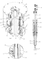
Fig. 6 is a longitudinal sectional view of a capping head of the turret shown inFig. 5 ; and -
Fig. 7 is an enlarged view of the region of the capping head where the guiding device according to the invention is located. - Referring to
Figs. 1 and 2 , the air cushion guiding device according to a first embodiment of the invention is generally denoted 1.Device 1 is a bushing comprising two coaxial cylindrical sleeves, i.e. aninner sleeve 10 and anouter sleeve 11, preferably but not necessarily having the same length. - The Figures also show a member, for instance a
shaft 2, arranged to be guided bydevice 1. More particularly, guidingdevice 1 is arranged to drive ashaft 2 into a rotary, translatory or roto-translatory movement relative to guidingdevice 1. Thus, it is possible, for instance, to apply a roto-translatory movement to eithershaft 2 or guidingdevice 1, or to apply one of the rotary or translatory movements toshaft 2 and to apply the other movement to guidingdevice 1. Reference symbol A denotes the longitudinal axis of both sleeves. -
Inner sleeve 10 of guidingdevice 1 has a plurality of radial throughholes 12.Such holes 12 havefirst ends 13 in communication with afirst gap 15 formed betweeninner sleeve 10 andshaft 2, andsecond ends 14 communicating, preferably directly, with asecond gap 16 formed betweeninner sleeve 10 andouter sleeve 11. Preferably,inner sleeve 10 further includes a plurality of channels (not shown in the Figures) establishing communication among the holes. -
Outer sleeve 11 of guidingdevice 1 has at least oneradial opening 17 communicating, preferably directly, with thesecond gap 16 and arranged to allow introduction of a pressurised fluid, e.g. air, from the outside. Such a fluid reaches thefirst gap 15 through thesecond gap 16 and the plurality of radial holes 12. - The presence of pressurised fluid in the
first gap 15 advantageously allows creating a fluidic gap (or cushion) in thefirst gap 15, betweeninner sleeve 10 andshaft 2. Thanks to such a fluidic gap,inner sleeve 10 andshaft 2 are prevented from coming into contact, both in static conditions and in conditions of relative rotary and/or translatory motion between the sleeve and the shaft. In this way, wear due to friction between guidingdevice 1 andshaft 2 is advantageously avoided. More particularly, a balance condition is defined in which longitudinal axis A of the inner and outer sleeves coincides with the shaft axis. In such a balance condition, the fluidic gap has uniform thickness. - Referring in particular to
Fig. 3 ,radial holes 12 are preferably uniformly distributed ininner sleeve 10 so as to ensure a uniform distribution of the fluid in thefirst gap 15 in the balance condition defined above. - Preferably, guiding
device 1 includes sealing elements with low frictional coefficient (not shown in the Figures) associated withinner sleeve 10 and arranged to cooperate withshaft 2. Such sealing elements allow limiting fluid leakage from thefirst gap 15, thereby reducing consumptions related with the introduction of pressurised fluid throughradial openings 17. - Preferably, through
holes 12 ofinner sleeve 10 haveend portions 18, directed towards the first ends 13 thereof, having a cross-section larger than the remaining cross-section ofholes 12. For instance, referring toFig. 4 ,such end portions 18 may have a frusto-conical shape with cross-sectional size progressively increasing towards the first ends 13 of the respective holes 12. At said ends 18, fluid volumes are created that have uniform pressure in balance conditions. The fluid pressure in a givenend portion 18 varies in inverse proportion to the thickness of the fluidic gap betweeninner sleeve 10 andshaft 2, that is to the thickness of thefirst gap 15, at saidend portion 18. In this manner, when the longitudinal axis ofshaft 2 does not coincide with axis A of guidingdevice 1 because of the relative movements between guidingdevice 1 andshaft 2, i.e. when the fluidic gap formed betweeninner sleeve 10 and shaft 2 (and hence the first gap 15) takes a non-uniform thickness and decreases on one side and increases on the radially opposite side, the pressure of the fluid volumes increases where the thickness of the fluidic gap is smaller and decreases where the thickness is greater. Thus, a pressure difference is created that pushes the shaft towards the side where the fluidic gap has a greater thickness, thereby tending to restore the balance condition in which the thickness of the fluidic gap is uniform or, otherwise stated, in whichshaft 2 is in coaxial position relative to guidingdevice 1. - In accordance with the first embodiment of the guiding device, it is possible to introduce fluid through one or more radial openings located on the side of the guiding device where the thickness of the fluidic gap is smaller. In this manner, the pressure difference between the holes directed towards the side of the guiding device where the thickness of the fluidic gap is smaller and the holes directed towards the opposite side can be increased, thereby compensating more quickly the displacement of
shaft 2, i.e. bringing it more quickly back to the balance condition. - In accordance with a second embodiment of the guiding device, the
second gap 16 betweeninner sleeve 10 andouter sleeve 11 is lacking. The inner sleeve includes a network of channels establishing communication betweenradial holes 12 ofinner sleeve 10, and the at least oneradial opening 17 ofouter sleeve 11 communicates, preferably directly, with a respective radial hole aligned with the same opening. In this embodiment, the fluid introduced into the at least oneradial opening 17 reaches thefirst gap 15 through the network of communication channels and radial holes 12. - In accordance with a third embodiment of the present invention,
outer sleeve 11 has at least tworadial openings 17 and thesecond gap 16 formed betweeninner sleeve 10 andouter sleeve 11 is divided into at least two sectors or segments that are not in direct communication with each other. Each sector of thesecond gap 16 communicates, preferably directly, with a correspondingradial opening 17 and with second ends 14 of a corresponding subset ofradial holes 12 ofinner sleeve 10. In this way, fluid introduced into aradial opening 17 reaches thefirst gap 15 through the respective sector of thesecond gap 16 and the corresponding subset ofradial holes 12 - In accordance with the guiding device of the third embodiment, it is possible to introduce pressurised fluid through one or more
radial openings 17, so as to cause a pressure increase in the only subsets ofholes 12 communicating with suchradial openings 17 through the respective sectors of thesecond gap 16. In case of displacement ofshaft 2 relative to the balance condition, this possibility can be advantageously exploited for increasing the pressure in the radial holes directed towards the side of the guiding device where the fluidic gap has a smaller thickness, thereby assisting in a quicker restoration of the balance condition. - In accordance with a fourth embodiment of the present invention, the
second gap 16 betweeninner sleeve 10 andouter sleeve 11 is lacking.Outer sleeve 11 has at least tworadial openings 17 andinner sleeve 10 includes at least two networks of channels establishing communication betweenradial holes 12 ofinner sleeve 10, the networks not being in direct communication with each other. Eachradial opening 17 communicates, preferably directly, with a respective radial hole aligned with the same opening and each network of channels is arranged to make the radial holes of a corresponding subset ofradial holes 12 ofinner sleeve 10 communicate with one another. In this way, the fluid introduced into aradial opening 17 reaches thefirst gap 15 through the respective network of channels and the corresponding subset of radial holes 12. - In accordance with the guiding device of the fourth embodiment, it is possible to introduce pressurised fluid through one or more
radial openings 17, so as to cause a pressure increase in the only subsets ofholes 12 communicating with suchradial openings 17 through the respective networks of channels. In case of displacement ofshaft 2 relative to the balance condition, this possibility can be advantageously exploited for increasing the pressure in the radial holes directed towards the side of the guiding device where the fluidic gap has a smaller thickness, thereby assisting in a quicker restoration of the balance condition. - Preferably, the guiding device according to the invention further includes pressure sensors and/or displacement sensors and/or gyroscopic sensors (not shown in the Figures), capable of detecting the relative displacements between guiding
device 1 andshaft 2, in particular a possible displacement ofshaft 2 relative to the balance condition. A control system (not shown in the Figures) is configured to control introduction of the pressurised fluid throughradial openings 17 ofouter sleeve 11. Advantageously, the control system can receive the data detected by such sensors, in particular a possible displacement ofshaft 2 relative to the balance condition, entailing a non-uniform thickness of the fluidic gap, and can control, based on such data, introduction of the pressurised fluid through one or more radial openings located on the side of the guiding device where the thickness of the fluidic gap is smaller, or anyway openings communicating with subsets of radial holes where the thickness of the fluidic gap is smaller. This allows, as explained before, compensating more quickly the misalignment of the member to be guided relative to the aforesaid balance condition. - Advantageously, the provision of fluid in the
first gap 15 formed betweeninner sleeve 10 andshaft 2 further allows removing possible particles of dust and material generated by wear, besides making use of lubricants superfluous. Such features makeguiding device 1 suitable for use in applications in which a clean environment is required. - The fluid introduced further contributes to cool both guiding
device 1 andshaft 2. Should guidingdevice 1 be mounted on a roto-translating motor, the fluid would allow, for instance, cooling the electromagnetic parts inside the motor. - Lastly, guiding
device 1 according to the invention has the advantage of having a compact structure, what makes the device suitable for use in applications requiring a reduced bulk. - The invention can find application in different technical fields, and is particularly suitable for guiding roto-translating shafts of capping heads for applying for instance screw or pressure caps to containers, more particularly bottles.
- In accordance with a further embodiment of the invention, the inner sleeve and the outer sleeve are made as an integral piece by means of the 3D printing technology (Additive Manufacturing).
-
Figs. 5 to 7 show the application of guidingdevice 1 according to the invention in one of such capping machines. As known, a capping machine generally comprises at least one capping head, in turn including a cap application part, equipped with a cap gripping member which is generally made to move according to a rotary movement about a longitudinal axis and a translatory movement along said axis, and a driving part, for instance located axially above the cap application part. The axial sliding of the gripping member also serves for applying a top load necessary to keep the container to be capped blocked during the capping operation. In conventional heads, one or more springs allow adjusting such a load. - More particularly,
Fig. 5 shows, by way of example, a capping turret 20 preferably including a plurality of capping heads 21, each incorporating guidingdevice 1. Turret 20 comprises astationary frame 22, inside which there is mounted a rotatingstructure 23, to which heads 21 are fixedly connected for rotation. Rotation ofstructure 23 allows bringing capping heads 21 in correspondence ofbottles 26. The means for causing rotation ofstructure 23 are conventional and are not shown. - Referring also to
Fig. 6 , eachhead 21 includes ashaft 24 which is to be driven into the roto-translatory motion necessary for the capping operations and which carries, at its bottom, grippingmember 25 for the cap to be applied to abottle 26. At its top,shaft 24 is provided withmeans 27 for connection to members belonging to the driving part (not shown) and causing the axial sliding of the head under the control, for instance, of cams. - Capping
head 21 includes acylindrical body 30 fixedly connected for rotation to rotatingstructure 23 of turret 20. More particularly,cylindrical bodies 30 of all heads are fastened to aflange 31 instructure 23.Cylindrical body 30 internally accommodatesstator 32 androtor 28 of an electric motor for generating the rotary motion to be imparted toshaft 24 through a coupling device of known type. Reference symbol B denotes the axis of rotation ofshaft 24. - Capping
head 21 includes, for instance in a bottom portion shown enlarged inFig, 7 , an air cushion guiding device similar to the device described above. Such a guiding device comprises an outercylindrical sleeve 35, similar toouter sleeve 11 of guidingdevice 1 described above and provided therefore with an opening (not shown) for the introduction of a pressurised fluid, and aninner sleeve 34, similar toinner sleeve 10 and provided therefore with a plurality of through holes (not shown) for the passage of the pressurised fluid and the creation of the fluidic gap betweeninner sleeve 34 and roto-translatingshaft 24. - As known, when a cap is to be applied to a
bottle 26, it is necessary to impart a roto-translatory motion torod 24 ofhead 21 concerned. The rotary and translatory movements allow bringing the cap, held bycap gripping member 25, in contact withbottle 26 and hence screwing or inserting the cap onto or intobottle 26. Guidingdevice 1 allows preventing axis B ofshaft 24 from becoming misaligned during its roto-translatory motion, and in particular during the phases of contact betweencap gripping member 25 andbottles 26 and of cap screwing or insertion. - It is clear that the above description is given only by way of non-limiting example and that changes and modifications are possible without departing from the scope of the invention as defined by the appended claims.
Claims (10)
- A fluid cushion guiding device (1) for guiding a shaft (2) into relative movement, rotary and translatory, relative to the guiding device (1), the guiding device (1) comprising an inner sleeve (10) and an outer sleeve (11) that are coaxial with each other, wherein the inner sleeve (10) has a plurality of radial holes (12) having first ends (13) communicating with a first sealed gap (15) provided between the inner sleeve (10) and the shaft (2) to be guided, wherein the guiding device (1) includes sealing elements with low frictional coefficient associated with the inner sleeve (10) and arranged to cooperate with the shaft (2), limiting fluid leakage from the first gap (15) and wherein the outer sleeve (11) has at least one radial opening (17) characterised in that the said radial opening (17) is arranged to allow introducing from the outside a pressurised fluid which, by reaching the first gap (15) through said holes (12), is suitable to create a gap of pressurised fluid between the inner sleeve (10) and the shaft (2) to be guided.
- The guiding device (1) according to claim 1, including a second gap (16) between the inner sleeve (10) and the outer sleeve (11), said second gap (16) communicating with the at least one radial opening (17) as well as with second ends (14) of the radial holes (12).
- The guiding device (1) according to claim 1 or 2, wherein the inner sleeve (10) includes a network of channels establishing communication among the radial holes (12).
- The guiding device (1) according to claim 2, wherein the outer sleeve (11) has at least two radial openings (17) and wherein the second gap (16) is divided into at least two sectors that are not in direct communication with each other, each sector of the second gap (16) communicating with a corresponding radial opening (17) and with the second ends (14) of a corresponding subset of radial holes (12) of the outer sleeve (11).
- The guiding device (1) according to claim 1, wherein the outer sleeve (11) has at least two radial openings (17) and the inner sleeve (10) includes at least two networks of channels establishing communication among radial holes (12), the at least two networks of channels not being in direct communication with each other and each network of channels communicating with a corresponding radial opening (17) and being arranged to make the radial holes of a corresponding subset of radial holes (12) of the outer sleeve (11) communicate with one another.
- The guiding device (1) according to claim 1, wherein the radial holes (12) of the inner sleeve (10) have end portions (18) facing the respective first ends (13), said end portions (18) having a cross-section larger than the remaining cross-section of the holes.
- The guiding device (1) according to any of the preceding claims, further including sensors capable of detecting relative movements between the guiding device (1) and the shaft (2) to be guided, and a control system configured to control introduction of the pressurised fluid through one or more radial opening(s) (17) of the outer sleeve (11) on the basis of the movements detected by said sensors, so as to compensate the displacement of the shaft (2) to be guided relative to a balance condition in which the shaft (2) to be guided is coaxial with the guiding device (1).
- The guiding device (1) according to any of the claims 1 to 6, wherein the inner sleeve (10) and the outer sleeve (11) are two separate sleeves.
- A capping head (21) including a cap application part (24, 25) equipped with a cap gripping member (25) and a shaft (24) that are arranged to move according to a rotary movement about a longitudinal axis (B) and a translatory movement along said axis, and a driving part (27, 28, 32) for said cap application part (24, 25), characterised in that the capping head (21) includes a fluid cushion guiding device (1) according to any of claims 1 to 8 suitable to guide the movements of the shaft (24).
- A turret (20) of a capping machine, including a plurality of capping heads (21) according to claim 9 mounted on a rotating structure (23) of the turret (20) and fixedly connected for rotation to said structure.
Applications Claiming Priority (2)
| Application Number | Priority Date | Filing Date | Title |
|---|---|---|---|
| IT102017000084319A IT201700084319A1 (en) | 2017-07-24 | 2017-07-24 | AIR CUSHION GUIDE DEVICE |
| PCT/IB2018/055329 WO2019021118A1 (en) | 2017-07-24 | 2018-07-18 | DEVICE FOR GUIDING FLUID CUSHION |
Publications (2)
| Publication Number | Publication Date |
|---|---|
| EP3658793A1 EP3658793A1 (en) | 2020-06-03 |
| EP3658793B1 true EP3658793B1 (en) | 2021-11-03 |
Family
ID=60451046
Family Applications (1)
| Application Number | Title | Priority Date | Filing Date |
|---|---|---|---|
| EP18750515.1A Active EP3658793B1 (en) | 2017-07-24 | 2018-07-18 | Fluid cushion guiding device |
Country Status (5)
| Country | Link |
|---|---|
| US (1) | US20210148405A1 (en) |
| EP (1) | EP3658793B1 (en) |
| CN (1) | CN110998111A (en) |
| IT (1) | IT201700084319A1 (en) |
| WO (1) | WO2019021118A1 (en) |
Families Citing this family (3)
| Publication number | Priority date | Publication date | Assignee | Title |
|---|---|---|---|---|
| IT201700084310A1 (en) | 2017-07-24 | 2019-01-24 | Arol Spa | MAGNETIC COUPLING DEVICE |
| IT202000014836A1 (en) | 2020-06-22 | 2021-12-22 | Arol Spa | CONTAINER HANDLING DEVICE FOR CORKING INSTALLATIONS |
| IT202200002780A1 (en) | 2022-02-15 | 2023-08-15 | Arol Spa | Roto-translating capping head with static drive unit |
Family Cites Families (17)
| Publication number | Priority date | Publication date | Assignee | Title |
|---|---|---|---|---|
| GB1013351A (en) * | 1963-10-24 | 1965-12-15 | Westwind Developments Ltd | Improvements in or relating to air driven turbines |
| AU462046B2 (en) * | 1971-12-30 | 1975-06-12 | Commonwealth Scientific And Industrial Research Organisation | Improved roller support for self-twist spinning machine |
| JPS60168917A (en) * | 1984-02-10 | 1985-09-02 | Nissan Motor Co Ltd | gas bearing device |
| US5649410A (en) * | 1994-06-10 | 1997-07-22 | Johnson & Johnson Vision Products, Inc. | Post-hydration method and apparatus for transporting, inspecting and packaging contact lenses |
| US6293184B1 (en) * | 1999-09-02 | 2001-09-25 | Sunpower, Inc. | Gas bearing and method of making a gas bearing for a free piston machine |
| JP4134541B2 (en) * | 2000-09-25 | 2008-08-20 | 株式会社ジェイテクト | Fluid bearing |
| ES2223765T3 (en) * | 2001-05-30 | 2005-03-01 | Procomac S.P.A. | ENCAPSULATED HEAD WITH MANDRIL STERILIZER. |
| CN100420866C (en) * | 2004-10-27 | 2008-09-24 | 日本电产株式会社 | Dynamic pressure bearing device |
| US7146781B1 (en) * | 2004-12-06 | 2006-12-12 | Nathan Albert Cole | Apparatus and method for insertion of material into uncontaminated containers |
| CN2822877Y (en) * | 2005-08-18 | 2006-10-04 | 无锡开源机床集团有限公司 | Grinding wheel main shaft structure for numerical control roller grinder |
| DE102006052427A1 (en) * | 2006-11-07 | 2008-05-08 | BSH Bosch und Siemens Hausgeräte GmbH | Gas bearing and bearing bush for it |
| US20080112658A1 (en) * | 2006-11-15 | 2008-05-15 | William Justin | Bushing for increased lubrication |
| CN103016530B (en) * | 2012-12-31 | 2014-12-10 | 浙江工业大学 | Rotary air supply device unaffected by air pipe bending disturbance |
| NL2013735B1 (en) * | 2014-11-04 | 2016-10-04 | Jbt B&Bs B V | Device for the filling and/or closing of containers having a drive shaft decontamination box. |
| CN204458834U (en) * | 2015-02-10 | 2015-07-08 | 东北林业大学 | A kind of dynamical and static pressure gas bearing |
| CN206329633U (en) * | 2016-11-03 | 2017-07-14 | 东北林业大学 | A kind of annular groove taper hole dynamical and static pressure gas bearing |
| CN106321634A (en) * | 2016-11-18 | 2017-01-11 | 广州市昊志机电股份有限公司 | Composite air flotation shafting structure |
-
2017
- 2017-07-24 IT IT102017000084319A patent/IT201700084319A1/en unknown
-
2018
- 2018-07-18 EP EP18750515.1A patent/EP3658793B1/en active Active
- 2018-07-18 CN CN201880049422.4A patent/CN110998111A/en active Pending
- 2018-07-18 WO PCT/IB2018/055329 patent/WO2019021118A1/en not_active Ceased
- 2018-07-18 US US16/633,481 patent/US20210148405A1/en not_active Abandoned
Also Published As
| Publication number | Publication date |
|---|---|
| EP3658793A1 (en) | 2020-06-03 |
| CN110998111A (en) | 2020-04-10 |
| US20210148405A1 (en) | 2021-05-20 |
| WO2019021118A1 (en) | 2019-01-31 |
| IT201700084319A1 (en) | 2019-01-24 |
Similar Documents
| Publication | Publication Date | Title |
|---|---|---|
| US11374481B2 (en) | Magnetic coupling device | |
| US20210148405A1 (en) | Fluid cushion guiding device | |
| US9169907B2 (en) | Spindle drive | |
| EP3558859B1 (en) | Actuation unit for a capping head and capping head using it | |
| CN113840795B (en) | Capping machine for applying caps to respective containers under aseptic or ultra-clean conditions | |
| KR20180130288A (en) | Spindle apparatus and method for operating the same | |
| EP2790306A2 (en) | Rotor-linear actuator | |
| EP2920489B1 (en) | Linear electro-mechanical actuator | |
| EP4019796B1 (en) | Brake assembly and robot joint with same, and robot | |
| CN111491886B (en) | Spindle unit for rotary closure of containers with screw closures | |
| KR20200142289A (en) | Master cylinder of brake for vehicle | |
| US12344210B2 (en) | Brake device for vehicle | |
| KR101957224B1 (en) | Drive for a machine, torque motor, clutch unit, device for processing materials, and use of a torque motor | |
| US6089266A (en) | Device for supplying a pressurized medium | |
| CN113994113A (en) | Sealing device | |
| US12570513B2 (en) | Rotating and translating capping head with static drive assembly | |
| GB2316721A (en) | Mechanical seal | |
| CN112879570B (en) | Spring mechanical seal compensating ring assembly | |
| US12297864B2 (en) | Self lubricating linear guide bushings for reciprocating canning and bottling machinery | |
| CN109080094B (en) | Screw driving device of injection molding machine | |
| CN122029123A (en) | Closure head for applying screw caps to containers, in particular containers in sterile space | |
| EP3361111B1 (en) | Linear stepper motor with rotor spindle for a linearly guided actuator | |
| CN104832452A (en) | Mechanical sealing device | |
| CN105207405A (en) | Electric cylinder linear transmission structure | |
| JPS59162326A (en) | Control device of phase angle |
Legal Events
| Date | Code | Title | Description |
|---|---|---|---|
| STAA | Information on the status of an ep patent application or granted ep patent |
Free format text: STATUS: UNKNOWN |
|
| STAA | Information on the status of an ep patent application or granted ep patent |
Free format text: STATUS: THE INTERNATIONAL PUBLICATION HAS BEEN MADE |
|
| PUAI | Public reference made under article 153(3) epc to a published international application that has entered the european phase |
Free format text: ORIGINAL CODE: 0009012 |
|
| STAA | Information on the status of an ep patent application or granted ep patent |
Free format text: STATUS: REQUEST FOR EXAMINATION WAS MADE |
|
| 17P | Request for examination filed |
Effective date: 20200130 |
|
| AK | Designated contracting states |
Kind code of ref document: A1 Designated state(s): AL AT BE BG CH CY CZ DE DK EE ES FI FR GB GR HR HU IE IS IT LI LT LU LV MC MK MT NL NO PL PT RO RS SE SI SK SM TR |
|
| AX | Request for extension of the european patent |
Extension state: BA ME |
|
| DAV | Request for validation of the european patent (deleted) | ||
| DAX | Request for extension of the european patent (deleted) | ||
| GRAP | Despatch of communication of intention to grant a patent |
Free format text: ORIGINAL CODE: EPIDOSNIGR1 |
|
| STAA | Information on the status of an ep patent application or granted ep patent |
Free format text: STATUS: GRANT OF PATENT IS INTENDED |
|
| INTG | Intention to grant announced |
Effective date: 20210527 |
|
| GRAS | Grant fee paid |
Free format text: ORIGINAL CODE: EPIDOSNIGR3 |
|
| GRAA | (expected) grant |
Free format text: ORIGINAL CODE: 0009210 |
|
| STAA | Information on the status of an ep patent application or granted ep patent |
Free format text: STATUS: THE PATENT HAS BEEN GRANTED |
|
| AK | Designated contracting states |
Kind code of ref document: B1 Designated state(s): AL AT BE BG CH CY CZ DE DK EE ES FI FR GB GR HR HU IE IS IT LI LT LU LV MC MK MT NL NO PL PT RO RS SE SI SK SM TR |
|
| REG | Reference to a national code |
Ref country code: GB Ref legal event code: FG4D |
|
| REG | Reference to a national code |
Ref country code: AT Ref legal event code: REF Ref document number: 1444211 Country of ref document: AT Kind code of ref document: T Effective date: 20211115 Ref country code: CH Ref legal event code: EP |
|
| REG | Reference to a national code |
Ref country code: IE Ref legal event code: FG4D |
|
| REG | Reference to a national code |
Ref country code: DE Ref legal event code: R096 Ref document number: 602018026121 Country of ref document: DE |
|
| REG | Reference to a national code |
Ref country code: LT Ref legal event code: MG9D |
|
| REG | Reference to a national code |
Ref country code: NL Ref legal event code: MP Effective date: 20211103 |
|
| REG | Reference to a national code |
Ref country code: AT Ref legal event code: MK05 Ref document number: 1444211 Country of ref document: AT Kind code of ref document: T Effective date: 20211103 |
|
| PG25 | Lapsed in a contracting state [announced via postgrant information from national office to epo] |
Ref country code: RS Free format text: LAPSE BECAUSE OF FAILURE TO SUBMIT A TRANSLATION OF THE DESCRIPTION OR TO PAY THE FEE WITHIN THE PRESCRIBED TIME-LIMIT Effective date: 20211103 Ref country code: LT Free format text: LAPSE BECAUSE OF FAILURE TO SUBMIT A TRANSLATION OF THE DESCRIPTION OR TO PAY THE FEE WITHIN THE PRESCRIBED TIME-LIMIT Effective date: 20211103 Ref country code: FI Free format text: LAPSE BECAUSE OF FAILURE TO SUBMIT A TRANSLATION OF THE DESCRIPTION OR TO PAY THE FEE WITHIN THE PRESCRIBED TIME-LIMIT Effective date: 20211103 Ref country code: BG Free format text: LAPSE BECAUSE OF FAILURE TO SUBMIT A TRANSLATION OF THE DESCRIPTION OR TO PAY THE FEE WITHIN THE PRESCRIBED TIME-LIMIT Effective date: 20220203 Ref country code: AT Free format text: LAPSE BECAUSE OF FAILURE TO SUBMIT A TRANSLATION OF THE DESCRIPTION OR TO PAY THE FEE WITHIN THE PRESCRIBED TIME-LIMIT Effective date: 20211103 |
|
| PG25 | Lapsed in a contracting state [announced via postgrant information from national office to epo] |
Ref country code: IS Free format text: LAPSE BECAUSE OF FAILURE TO SUBMIT A TRANSLATION OF THE DESCRIPTION OR TO PAY THE FEE WITHIN THE PRESCRIBED TIME-LIMIT Effective date: 20220303 Ref country code: SE Free format text: LAPSE BECAUSE OF FAILURE TO SUBMIT A TRANSLATION OF THE DESCRIPTION OR TO PAY THE FEE WITHIN THE PRESCRIBED TIME-LIMIT Effective date: 20211103 Ref country code: PT Free format text: LAPSE BECAUSE OF FAILURE TO SUBMIT A TRANSLATION OF THE DESCRIPTION OR TO PAY THE FEE WITHIN THE PRESCRIBED TIME-LIMIT Effective date: 20220303 Ref country code: PL Free format text: LAPSE BECAUSE OF FAILURE TO SUBMIT A TRANSLATION OF THE DESCRIPTION OR TO PAY THE FEE WITHIN THE PRESCRIBED TIME-LIMIT Effective date: 20211103 Ref country code: NO Free format text: LAPSE BECAUSE OF FAILURE TO SUBMIT A TRANSLATION OF THE DESCRIPTION OR TO PAY THE FEE WITHIN THE PRESCRIBED TIME-LIMIT Effective date: 20220203 Ref country code: NL Free format text: LAPSE BECAUSE OF FAILURE TO SUBMIT A TRANSLATION OF THE DESCRIPTION OR TO PAY THE FEE WITHIN THE PRESCRIBED TIME-LIMIT Effective date: 20211103 Ref country code: LV Free format text: LAPSE BECAUSE OF FAILURE TO SUBMIT A TRANSLATION OF THE DESCRIPTION OR TO PAY THE FEE WITHIN THE PRESCRIBED TIME-LIMIT Effective date: 20211103 Ref country code: HR Free format text: LAPSE BECAUSE OF FAILURE TO SUBMIT A TRANSLATION OF THE DESCRIPTION OR TO PAY THE FEE WITHIN THE PRESCRIBED TIME-LIMIT Effective date: 20211103 Ref country code: GR Free format text: LAPSE BECAUSE OF FAILURE TO SUBMIT A TRANSLATION OF THE DESCRIPTION OR TO PAY THE FEE WITHIN THE PRESCRIBED TIME-LIMIT Effective date: 20220204 Ref country code: ES Free format text: LAPSE BECAUSE OF FAILURE TO SUBMIT A TRANSLATION OF THE DESCRIPTION OR TO PAY THE FEE WITHIN THE PRESCRIBED TIME-LIMIT Effective date: 20211103 |
|
| PG25 | Lapsed in a contracting state [announced via postgrant information from national office to epo] |
Ref country code: SM Free format text: LAPSE BECAUSE OF FAILURE TO SUBMIT A TRANSLATION OF THE DESCRIPTION OR TO PAY THE FEE WITHIN THE PRESCRIBED TIME-LIMIT Effective date: 20211103 Ref country code: SK Free format text: LAPSE BECAUSE OF FAILURE TO SUBMIT A TRANSLATION OF THE DESCRIPTION OR TO PAY THE FEE WITHIN THE PRESCRIBED TIME-LIMIT Effective date: 20211103 Ref country code: RO Free format text: LAPSE BECAUSE OF FAILURE TO SUBMIT A TRANSLATION OF THE DESCRIPTION OR TO PAY THE FEE WITHIN THE PRESCRIBED TIME-LIMIT Effective date: 20211103 Ref country code: EE Free format text: LAPSE BECAUSE OF FAILURE TO SUBMIT A TRANSLATION OF THE DESCRIPTION OR TO PAY THE FEE WITHIN THE PRESCRIBED TIME-LIMIT Effective date: 20211103 Ref country code: DK Free format text: LAPSE BECAUSE OF FAILURE TO SUBMIT A TRANSLATION OF THE DESCRIPTION OR TO PAY THE FEE WITHIN THE PRESCRIBED TIME-LIMIT Effective date: 20211103 Ref country code: CZ Free format text: LAPSE BECAUSE OF FAILURE TO SUBMIT A TRANSLATION OF THE DESCRIPTION OR TO PAY THE FEE WITHIN THE PRESCRIBED TIME-LIMIT Effective date: 20211103 |
|
| REG | Reference to a national code |
Ref country code: DE Ref legal event code: R097 Ref document number: 602018026121 Country of ref document: DE |
|
| PLBE | No opposition filed within time limit |
Free format text: ORIGINAL CODE: 0009261 |
|
| STAA | Information on the status of an ep patent application or granted ep patent |
Free format text: STATUS: NO OPPOSITION FILED WITHIN TIME LIMIT |
|
| 26N | No opposition filed |
Effective date: 20220804 |
|
| PG25 | Lapsed in a contracting state [announced via postgrant information from national office to epo] |
Ref country code: AL Free format text: LAPSE BECAUSE OF FAILURE TO SUBMIT A TRANSLATION OF THE DESCRIPTION OR TO PAY THE FEE WITHIN THE PRESCRIBED TIME-LIMIT Effective date: 20211103 |
|
| PG25 | Lapsed in a contracting state [announced via postgrant information from national office to epo] |
Ref country code: SI Free format text: LAPSE BECAUSE OF FAILURE TO SUBMIT A TRANSLATION OF THE DESCRIPTION OR TO PAY THE FEE WITHIN THE PRESCRIBED TIME-LIMIT Effective date: 20211103 |
|
| REG | Reference to a national code |
Ref country code: DE Ref legal event code: R119 Ref document number: 602018026121 Country of ref document: DE |
|
| PG25 | Lapsed in a contracting state [announced via postgrant information from national office to epo] |
Ref country code: MC Free format text: LAPSE BECAUSE OF FAILURE TO SUBMIT A TRANSLATION OF THE DESCRIPTION OR TO PAY THE FEE WITHIN THE PRESCRIBED TIME-LIMIT Effective date: 20211103 |
|
| REG | Reference to a national code |
Ref country code: CH Ref legal event code: PL |
|
| GBPC | Gb: european patent ceased through non-payment of renewal fee |
Effective date: 20220718 |
|
| REG | Reference to a national code |
Ref country code: BE Ref legal event code: MM Effective date: 20220731 |
|
| PG25 | Lapsed in a contracting state [announced via postgrant information from national office to epo] |
Ref country code: LU Free format text: LAPSE BECAUSE OF NON-PAYMENT OF DUE FEES Effective date: 20220718 Ref country code: LI Free format text: LAPSE BECAUSE OF NON-PAYMENT OF DUE FEES Effective date: 20220731 Ref country code: FR Free format text: LAPSE BECAUSE OF NON-PAYMENT OF DUE FEES Effective date: 20220731 Ref country code: CH Free format text: LAPSE BECAUSE OF NON-PAYMENT OF DUE FEES Effective date: 20220731 |
|
| PG25 | Lapsed in a contracting state [announced via postgrant information from national office to epo] |
Ref country code: GB Free format text: LAPSE BECAUSE OF NON-PAYMENT OF DUE FEES Effective date: 20220718 Ref country code: BE Free format text: LAPSE BECAUSE OF NON-PAYMENT OF DUE FEES Effective date: 20220731 Ref country code: DE Free format text: LAPSE BECAUSE OF NON-PAYMENT OF DUE FEES Effective date: 20230201 |
|
| PG25 | Lapsed in a contracting state [announced via postgrant information from national office to epo] |
Ref country code: IE Free format text: LAPSE BECAUSE OF NON-PAYMENT OF DUE FEES Effective date: 20220718 |
|
| PG25 | Lapsed in a contracting state [announced via postgrant information from national office to epo] |
Ref country code: MK Free format text: LAPSE BECAUSE OF FAILURE TO SUBMIT A TRANSLATION OF THE DESCRIPTION OR TO PAY THE FEE WITHIN THE PRESCRIBED TIME-LIMIT Effective date: 20211103 Ref country code: CY Free format text: LAPSE BECAUSE OF FAILURE TO SUBMIT A TRANSLATION OF THE DESCRIPTION OR TO PAY THE FEE WITHIN THE PRESCRIBED TIME-LIMIT Effective date: 20211103 |
|
| PG25 | Lapsed in a contracting state [announced via postgrant information from national office to epo] |
Ref country code: HU Free format text: LAPSE BECAUSE OF FAILURE TO SUBMIT A TRANSLATION OF THE DESCRIPTION OR TO PAY THE FEE WITHIN THE PRESCRIBED TIME-LIMIT; INVALID AB INITIO Effective date: 20180718 |
|
| PG25 | Lapsed in a contracting state [announced via postgrant information from national office to epo] |
Ref country code: MT Free format text: LAPSE BECAUSE OF FAILURE TO SUBMIT A TRANSLATION OF THE DESCRIPTION OR TO PAY THE FEE WITHIN THE PRESCRIBED TIME-LIMIT Effective date: 20211103 |
|
| PGFP | Annual fee paid to national office [announced via postgrant information from national office to epo] |
Ref country code: IT Payment date: 20250709 Year of fee payment: 8 |
|
| PG25 | Lapsed in a contracting state [announced via postgrant information from national office to epo] |
Ref country code: TR Free format text: LAPSE BECAUSE OF FAILURE TO SUBMIT A TRANSLATION OF THE DESCRIPTION OR TO PAY THE FEE WITHIN THE PRESCRIBED TIME-LIMIT Effective date: 20211103 |