EP3658761B1 - Nacelle with thrust reverser - Google Patents
Nacelle with thrust reverser Download PDFInfo
- Publication number
- EP3658761B1 EP3658761B1 EP18752206.5A EP18752206A EP3658761B1 EP 3658761 B1 EP3658761 B1 EP 3658761B1 EP 18752206 A EP18752206 A EP 18752206A EP 3658761 B1 EP3658761 B1 EP 3658761B1
- Authority
- EP
- European Patent Office
- Prior art keywords
- blocking panel
- translating cowl
- outer casing
- track
- nacelle
- Prior art date
- Legal status (The legal status is an assumption and is not a legal conclusion. Google has not performed a legal analysis and makes no representation as to the accuracy of the status listed.)
- Not-in-force
Links
Images




Classifications
-
- F—MECHANICAL ENGINEERING; LIGHTING; HEATING; WEAPONS; BLASTING
- F02—COMBUSTION ENGINES; HOT-GAS OR COMBUSTION-PRODUCT ENGINE PLANTS
- F02K—JET-PROPULSION PLANTS
- F02K1/00—Plants characterised by the form or arrangement of the jet pipe or nozzle; Jet pipes or nozzles peculiar thereto
- F02K1/54—Nozzles having means for reversing jet thrust
- F02K1/64—Reversing fan flow
- F02K1/70—Reversing fan flow using thrust reverser flaps or doors mounted on the fan housing
- F02K1/72—Reversing fan flow using thrust reverser flaps or doors mounted on the fan housing the aft end of the fan housing being movable to uncover openings in the fan housing for the reversed flow
-
- F—MECHANICAL ENGINEERING; LIGHTING; HEATING; WEAPONS; BLASTING
- F01—MACHINES OR ENGINES IN GENERAL; ENGINE PLANTS IN GENERAL; STEAM ENGINES
- F01D—NON-POSITIVE DISPLACEMENT MACHINES OR ENGINES, e.g. STEAM TURBINES
- F01D17/00—Regulating or controlling by varying flow
- F01D17/10—Final actuators
- F01D17/12—Final actuators arranged in stator parts
- F01D17/14—Final actuators arranged in stator parts varying effective cross-sectional area of nozzles or guide conduits
-
- F—MECHANICAL ENGINEERING; LIGHTING; HEATING; WEAPONS; BLASTING
- F02—COMBUSTION ENGINES; HOT-GAS OR COMBUSTION-PRODUCT ENGINE PLANTS
- F02K—JET-PROPULSION PLANTS
- F02K1/00—Plants characterised by the form or arrangement of the jet pipe or nozzle; Jet pipes or nozzles peculiar thereto
- F02K1/06—Varying effective area of jet pipe or nozzle
- F02K1/12—Varying effective area of jet pipe or nozzle by means of pivoted flaps
-
- F—MECHANICAL ENGINEERING; LIGHTING; HEATING; WEAPONS; BLASTING
- F02—COMBUSTION ENGINES; HOT-GAS OR COMBUSTION-PRODUCT ENGINE PLANTS
- F02K—JET-PROPULSION PLANTS
- F02K1/00—Plants characterised by the form or arrangement of the jet pipe or nozzle; Jet pipes or nozzles peculiar thereto
- F02K1/54—Nozzles having means for reversing jet thrust
- F02K1/56—Reversing jet main flow
-
- F—MECHANICAL ENGINEERING; LIGHTING; HEATING; WEAPONS; BLASTING
- F05—INDEXING SCHEMES RELATING TO ENGINES OR PUMPS IN VARIOUS SUBCLASSES OF CLASSES F01-F04
- F05D—INDEXING SCHEME FOR ASPECTS RELATING TO NON-POSITIVE-DISPLACEMENT MACHINES OR ENGINES, GAS-TURBINES OR JET-PROPULSION PLANTS
- F05D2250/00—Geometry
- F05D2250/40—Movement of components
-
- F—MECHANICAL ENGINEERING; LIGHTING; HEATING; WEAPONS; BLASTING
- F05—INDEXING SCHEMES RELATING TO ENGINES OR PUMPS IN VARIOUS SUBCLASSES OF CLASSES F01-F04
- F05D—INDEXING SCHEME FOR ASPECTS RELATING TO NON-POSITIVE-DISPLACEMENT MACHINES OR ENGINES, GAS-TURBINES OR JET-PROPULSION PLANTS
- F05D2260/00—Function
- F05D2260/50—Kinematic linkage, i.e. transmission of position
- F05D2260/56—Kinematic linkage, i.e. transmission of position using cams or eccentrics
-
- F—MECHANICAL ENGINEERING; LIGHTING; HEATING; WEAPONS; BLASTING
- F05—INDEXING SCHEMES RELATING TO ENGINES OR PUMPS IN VARIOUS SUBCLASSES OF CLASSES F01-F04
- F05D—INDEXING SCHEME FOR ASPECTS RELATING TO NON-POSITIVE-DISPLACEMENT MACHINES OR ENGINES, GAS-TURBINES OR JET-PROPULSION PLANTS
- F05D2260/00—Function
- F05D2260/60—Fluid transfer
- F05D2260/606—Bypassing the fluid
Definitions
- This application relates generally to aircraft engine nacelles and, more particularly, to thrust reversers provided in such nacelles.
- Thrust reversers typically include movable blocking panels which are moved to prevent at least part of the bypass flow from being expelled through the engine aft exhaust aperture and to re-direct the bypass flow forwardly through an aperture created by a translating cowl.
- Known thrust reversers include drag links supporting and guiding the motion of the blocking panels within the bypass passage.
- the drag links can define complex assemblies, and may also protrude within the bypass passage during normal flight thus resulting in unwanted drag losses.
- Some conventional blocking panels are located on the inner surface of the translating cowl and accordingly exposed to the bypass flow when stowed. Such blocking panels may accordingly impact the aerodynamic flow efficiency in the bypass passage, for example due to steps and gaps defined between and around the panels.
- US5983625 describes a turbojet engine thrust reverser with a thrust reverser door with forward and rear portions, a first opening in the forward portion, a second opening in the rear portion and a passage communicating with the first and second openings.
- the thrust reverser door is pivotally attached to the cowling adjacent to the rear portion of the door so as to be movable between a forward thrust position, wherein the thrust reverser door covers the at least one reverse thrust opening in the cowling such that an inner surface of the thrust reverser door forms a portion of the boundary of the gas flow duct and wherein the first opening is blocked by the cowling, and a reverse thrust position wherein the forward portion of the thrust reverser door extends into the gas flow duct to direct at least a portion of the gas in the gas flow duct into the passage so as to generate a reverse thrust force.
- a panel is located so as to cover the second opening in the thrust reverser door when the thrust reverser door is in the forward thrust position and to uncover the second opening when the door is in the reverse thrust position.
- GB1345337 describes a gas turbine engine that has a gas flow duct between a gas generator casing and a fan cowl wall.
- Peripherally spaced blocker doors when inoperative, block respective apertures in the wall and are each pivotally mounted at the centre to a rigid structure upstream of the apertures and movably mounted at their downstream end to a cam track which the end of the door follows; and blocker door actuating means.
- the shape of the cam track causes the doors to move into or block the gas flow through the duct so that the resultant of the force of the gas flowing through the duct and the reaction force of the door mounting means causes the doors to move to the inoperative position until the engine resultant thrust is zero when the direction of the resultant force reverses.
- a nacelle for an aircraft comprising: an outer casing having a longitudinal axis; a thrust reverser including: a translating cowl, the outer casing and translating cowl cooperating to define an outer boundary of a bypass passage configured to surround an engine, the translating cowl movable relative to the outer casing along the longitudinal axis between a closed position and an open position, the translating cowl in the open position being axially spaced from the outer casing so as to define an opening between the translating cowl and the outer casing; and a blocking panel pivotable about a pivot connection between a stowed position in which the blocking panel is located radially outwardly of the bypass passage; and a pivoted position, the blocking panel in the pivoted position extending within the bypass passage adjacent the opening to direct a flow toward the opening; wherein the blocking panel is connected to the translating cowl by a sliding connection including an engagement member slidingly engaged in a track, the track having a first portion parallel to the longitudinal axis and a second portion non
- the nacelle may include any one or any suitable combination of the following:
- a nacelle for an aircraft comprising: an outer casing having a longitudinal axis; a translating cowl cooperating with the outer casing to define an outer boundary of a bypass passage configured to surround an engine, the translating cowl movable relative to the outer casing along the longitudinal axis; a blocking panel connected to the outer casing by a pivot connection and connected to the translating cowl by a sliding connection, the sliding connection including an engagement member slidingly engaged in a track, the track having a first portion parallel to the longitudinal axis and a second portion non-parallel to the longitudinal axis; wherein the translating cowl and the blocking panel define at least part of a thrust reverser selectively configurable between: a closed configuration where the translating cowl abuts the outer casing, the blocking panel has a stowed position radially outwardly of the bypass passage, and the engagement member is located in the first portion of the track, a deployed configuration where the translating cowl is spaced a first distance from the outer casing so
- the nacelle may include any one or any suitable combination of the following:
- a nacelle for an aircraft comprising: an outer casing defining an outer wall of a portion of a bypass passage, the bypass passage configured to surround an engine; a translating cowl movable axially in relation to the outer casing between a closed position and an open position, wherein in the open position an opening is defined between the outer casing and the translating cowl; and a blocking panel comprising a forward end and a rear end, the blocking panel being pivotable between a stowed position and a pivoted position; wherein in the pivoted position: the blocking panel extends within the bypass passage adjacent the opening to direct a flow toward the opening; and the forward end of the blocking panel is located radially outwardly of the rear end.
- a method of deploying a thrust reverser for an aircraft engine including a translating cowl and a blocking panel slidingly interconnected by an engagement member received in a track
- the method comprising: moving the translating cowl away from an outer casing along a longitudinal axis of the outer casing until the translating cowl reaches an open position, the outer casing and translating cowl defining an outer boundary of a bypass passage surrounding the engine, wherein moving the translating cowl includes: moving the translating cowl away from the outer casing without moving the blocking panel relative to the outer casing until the translating cowl reaches an intermediate position and while the engagement member slides in a portion of the track parallel to the longitudinal axis; and moving the translating cowl away from the outer casing from the intermediate position to the open position to pivot the blocking panel by sliding the engagement member in a second portion of the track non-parallel to the longitudinal axis, the blocking panel pivoting from a position located radially outwardly of the bypass passage to a position where the blocking panel
- the method may include any one or any suitable combination of the following:
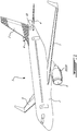
- the aircraft 1 has a fuselage 2 having a fore end at which a cockpit is located, and an aft end supporting a tail assembly, with the cabin generally located between the cockpit and the tail assembly.
- the tail assembly comprises a vertical stabilizer 3 with a rudder, and horizontal stabilizers 4 with elevators.
- the tail assembly has a fuselage-mounted tail, but other configurations may also be used for the aircraft 1, such as cruciform, T-tail, etc.
- Wings 5 project laterally from the fuselage.
- the aircraft 1 has engines 6 contained in nacelles 10, 110 supported by the wings 5, although the nacelles 10, 110 could also be mounted to the fuselage 2.
- Each nacelle 10, 110 defines an aerodynamic outer surface around the engine 6 and may also define air passages in communication with the engine 6. Although two engines 6 are shown, it is understood that the aircraft 2 can have a single engine or more than two engines.
- the nacelle 10 includes an outer casing 12 which is annular and has a longitudinal axis L.
- the outer casing 12 has an annular outer wall 14f which surrounds an upstream portion of an annular bypass passage 16 defined around the engine (not shown, but the location of which being identified at 6); the bypass passage 16 may be configured for example to receive a flow of air driven by a fan of the engine and bypassing the engine core, and mixed with the engine exhaust downstream of combustion.
- the outer casing 12 also includes an annular exterior wall 18f radially outwardly spaced from the outer wall 14f so that a cavity 20f is defined between the outer wall 14f and the exterior wall 18f.
- the exterior wall 18f defines part of the outer surface 22 of the nacelle 10 exposed to the atmosphere.
- the outer wall 14f defines an outer boundary 24 of the bypass passage 16 and is exposed to the bypass flow B circulating through the bypass passage 16.
- An inner wall 26 of the bypass passage 16 is defined by an annular inner casing 28 located radially inwardly of the outer wall 14f. The inner casing 28 separates the bypass flow B from the engine 6, so as to separate the bypass flow B from the main combustion flow.
- the outer casing 12 is a fixed structure, i.e. it has a fixed position relative to the inner casing 28 and with respect to the engine 6.
- the outer casing 12 and inner casing 28 may be interconnected through any suitable type of connection (not shown).
- the nacelle 10 includes a thrust reverser 30 which is shown in Figs. 2-3 in a closed configuration and in Figs. 4-5 in a deployed configuration.
- the thrust reverser 30 is configured to redirect a portion P of the bypass flow B toward the front of the nacelle 10 (left side of Fig. 4 ) so as to provide a reversed thrust to slow down the aircraft.
- the thrust reverser 30 generally includes one or more translating cowl(s) 32 and one or more blocking panel(s) 34, one of each being shown in the Figures. In a particular embodiment and as can be best seen in Fig.
- each translating cowl 32 and each blocking panel 34 extends around an arc of about 180 degrees; the other half of the nacelle 10 not shown in the Figure is a mirror image of the portion shown, so that the thrust reverser 30 includes two translating cowls 32 and two blocking panels 34. It is understood that alternately the thrust reverser 30 may include a single translating cowl 32 and/or a single blocking panel 34, or more than two translating cowls 32 and/or blocking panels 34, each spanning across a respective arc of the nacelle 10 sufficient to provide a desired reversed thrust when deployed.
- the translating cowl 32 has an arcuate outer wall 14t which surrounds a downstream portion of the bypass passage 16.
- the translating cowl 32 also includes an arcuate exterior wall 18t concentric with and radially outwardly spaced from the outer wall 14t so that a cavity 20t is defined between the outer wall 14t and the exterior wall 18t.
- the translating cowl 32 is movable along the longitudinal axis L between a closed position ( Figs. 2-3 ) and an open position ( Fig. 4-5 ). In the closed position and as can be best seen in Fig.
- the translating cowl 32 abuts the outer casing 12, with the outer walls 14f, 14t of the outer casing 12 and translating cowl 32 cooperating to define a continuous outer boundary 24 of the bypass passage 16 exposed to the bypass flow B, and with the exterior walls 18f, 18t of the outer casing 12 and translating cowl 32 cooperating to define a continuous outer surface 22 of the nacelle 10 exposed to atmosphere.
- the translating cowl 32 In the open position and as can be best seen in Fig. 4 , the translating cowl 32 is axially spaced from the outer casing 12 so as to define an opening 36 therebetween, created by the space between the outer walls 14f, 14t and the corresponding space between the exterior walls 18f, 18t (illustrated by distance d). At least a portion P of the bypass flow B escapes the bypass passage 16 and the nacelle 10 through the opening 36.
- suitable vanes for example, extending rearwardly from the outer casing 12 and received in the cavity 20t of the translating cowl 32 when the translating cowl 32 is in the closed position
- the blocking panel 34 is connected to the outer casing 12 by a pivot connection 38.
- the pivot connection 38 is defined at the rear end of the blocking panel 34.
- the pivot connection 38 includes two spaced apart pivots 38' defining a pivot axis A orthogonal to the longitudinal axis L; it is understood that altemately, a single pivot or more than two pivots can be provided, for example depending on the size of the blocking panel 34.
- the pivot connection 38 (e.g., pivots 38') is located radially outwardly of the outer walls 14f, 14t and radially outwardly of the bypass passage 16.
- the pivot connection 38 (e.g., pivots 38') is also located radially inwardly of the exterior walls 18f, 18t, so as to be contained within the cavity 20f, 20t of the outer casing 12 and/or of the translating cowl 32.
- the blocking panel 34 is pivotable about the pivot connection 38 between a stowed position ( Figs. 2-3 ) and a pivoted position ( Figs. 4-5 ).
- the blocking panel 34 in the stowed position and as can be best seen in Fig. 3 , the blocking panel 34 is located radially outwardly of the outer walls 14f, 14t and of the bypass passage 16.
- the blocking panel 34 is also located radially inwardly of the exterior walls 18f, 18t, so as to be contained within the cavity 20f, 20t of the outer casing 12 and/or of the translating cowl 32.
- Fig. 3 the blocking panel 34 is located radially outwardly of the outer walls 14f, 14t and of the bypass passage 16.
- the blocking panel 34 is also located radially inwardly of the exterior walls 18f, 18t, so as to be contained within the cavity 20f, 20t of the outer casing 12 and/or of the translating cowl 32.
- the blocking panel 34 extends in part within the cavity 20t of the translating cowl 32 and in part within the cavity 20f of the outer casing 12 when the blocking panel 34 is in the stowed position and the translating cowl 32 is in the closed position; in other words, the blocking panel 34 extends in part within the translating cowl 32 and in part within the outer casing 12 when the thrust reverser 30 is in the closed configuration.
- the blocking panel 34 extends within the bypass passage 16 adjacent the opening 36 to direct at least a portion P of the bypass flow B toward and out of the opening 36.
- the blocking panel 34 in the pivoted position is angled so that its forward end is located radially outwardly of its rear end, and the blocking panel 34 protrudes through the opening 36, i.e. part of the blocking panel 34 extends radially outwardly of at least the outer walls 14f, 14t, and in a particular embodiment also extends radially outwardly of the exterior walls 18f, 18t.
- Other configurations are possible.
- the blocking panel 34 is also connected to the translating cowl 32, by a sliding connection 40 including an engagement member 42 slidingly engaged in a track 44.
- track as used herein is intended to encompass any suitable structure allowing to slidingly receive and guide a sliding movement of a complementary engagement member, including, but not limited to, a slot defined in a structure configured to slidingly receive and guide the complementary engagement member, and two spaced apart rails protruding from a structure with the space between the rails being configured to slidingly receive and guide the complementary engagement member.
- the engagement member is a spigot; it is however understood that the engagement member may have any suitable shape.
- the pivot connection 38 is located aft of the track 44 when the blocking panel 34 is in the stowed position.
- the sliding connection 40 includes two tracks 44 and two engagement members 42; each track 44 is connected to the blocking panel 34 and each engagement member 42 protrudes from the translating cowl 32.
- the tracks 44 are circumferentially spaced from each other, and circumferentially located between the two pivots 38'. Other configurations are also possible.
- the track 44 has a first portion 44a parallel to the longitudinal axis L and a second portion 44b non-parallel to the longitudinal axis L.
- the second portion 44b extends from the first portion 44a toward the longitudinal axis L, and is located rearwardly of the first portion 44a.
- the engagement member 42 is received in the first portion 44a of the track when the thrust reverser 30 is in the closed configuration ( Figs. 2-3 ) and in the second portion 44b of the track when the thrust reverser 30 is in the deployed configuration ( Figs. 4-5 ).
- the configuration of the thrust reverser 30 is changed through the sliding motion of the translating cowl 32, which may be driven by any suitable type of actuation mechanism (not shown), including, but not limited to, linearly extending hydraulic actuators.
- the sliding motion of the translating cowl 32 causes the pivoting motion of the blocking panel 34 about the pivot connection 38 due to the sliding connection 40, which is configured so that the translating cowl 32 causes pivoting of the blocking panel 34 during only part of the motion of the translating cowl 32, as described in the following.
- the motion of the translating cowl 32 along the longitudinal axis L slides the engagement member 42 within the track 44. It can be seen from the comparison of Figs. 2 , 6a and 6b that the motion of the translating cowl 32 is performed without moving the blocking panel 34 when the engagement member 42 slides within the first, longitudinal portion 44a of the track 44, i.e. the blocking panel 34 remains in the stowed position. Between a predetermined intermediate configuration where the engagement member 42 is at the junction of the first and second portions 44a, 44b ( Fig. 6b ) and the deployed configuration, as can be seen from the comparison of Figs.
- the motion of the translating cowl 32 causes the blocking panel 34 to pivot about the pivot connection 40 between the stowed and pivoted positions when the engagement member 42 slides within the second, angled portion 44b of the track 44.
- the pivoting motion of the blocking panel 34 is guided by the interaction between the engagement member 42 and the walls of the track 44.
- the engagement member 42 slides in the second portion 44b of the track 44 first toward the end of the track 44, i.e. away from the first portion 44a, and then back toward the first portion 44a, while remaining within the second portion 44b, as the blocking panel 34 pivots from the stowed to the pivoted positions.
- a nacelle 110 according to another embodiment is generally shown, where elements similar to that of the nacelle 10 of Figs. 2-6c are identified by the same reference numerals and will not be further described herein.
- the nacelle 110 differs from the previously shown and described nacelle 10 in that the track 144 of the sliding connection 140 is connected to the translating cowl 32 and the engagement member 142 protrudes from the blocking panel 34. Accordingly, the second portion 144b of the track 144 extends from the first portion 144a away from the longitudinal axis L, and is located in front of the first portion 144a.
- 7-9 is configurable between the closed configuration ( Figs. 7-8 ) and the deployed configuration ( Fig. 9 ) by the motion of the translating cowl 32 along the longitudinal axis L, with the interaction between the engagement member 142 and the track 144 causing the blocking panel 34 to remain in the stowed position between the closed configuration and an intermediate configuration as the engagement member 142 slides within the first, longitudinal portion 144a of the track 144, and to pivot about its pivot connection 38 with the outer casing 12 between the stowed and the pivoted positions as the engagement member 142 slides within the second, angled portion 144b of the track 144.
- the thrust reverser 30, 130 can thus be deployed by moving the translating cowl 32 away from the outer casing 12 along the longitudinal axis L of the casing 12 until the translating cowl 32 reaches the open position; this includes moving the translating cowl 32 away from the outer casing 12 without moving the blocking panel 34 relative to the outer casing 12 until the translating cowl 32 reaches an intermediate position, with the blocking panel 34 remaining radially outward of the bypass passage 16 and the engagement member 42, 142 sliding in the portion of the track 44a, 144a extending parallel to the longitudinal axis L, and then moving the translating cowl 32 away from the outer casing 12 from the intermediate position to the open position to pivot the blocking panel 34 about the pivot connection 38 by sliding the engagement member 42, 142 in the portion of the track 44b, 144b extending non-parallel to the longitudinal axis L, with the blocking panel 34 pivoting to the deployed position.
- the translating cowl 32 moves rearwardly away from the outer casing 12 to reach the open position.
- the blocking panel 34 is pivoted until it protrudes through the opening 36 between the translating cowl 32 and the outer casing 12.
- the sliding connection 40, 140 thus provides a mechanical link between the translating cowl 32 and the blocking panel 34 which allows a constant linear motion of the translating cowl 32 while allowing the blocking panel 34 to remain stationary during part of the linear motion of the translating cowl 32 and to pivot during the remaining part of the linear motion of the translating cowl 32.
- the sliding connection 40, 140 and the pivot connection 38 support the blocking panel 34 while remaining at all times radially outward of the outer wall 14f, 14t of the casing 12 and of the thrust reverser 30, 130, i.e. while remaining outside of the bypass passage 16.
- the blocking panel 34 also remains outside of the bypass passage 16 when not deployed.
- the thrust reverser 30, 130 accordingly does not impact the bypass flow B when in the closed configuration, i.e. during normal flight operations.
- the thrust reverser 30, 130 with the sliding connection 40, 140 provides for low drag and thus improved engine/aircraft performance, reduced cost and weight due to a reduced number of parts, and/or reduced maintenance costs due to the reduced number of parts, when compared with a thrust reverser including drag links.
Landscapes
- Engineering & Computer Science (AREA)
- Mechanical Engineering (AREA)
- General Engineering & Computer Science (AREA)
- Chemical & Material Sciences (AREA)
- Combustion & Propulsion (AREA)
- Structures Of Non-Positive Displacement Pumps (AREA)
- Wind Motors (AREA)
Description
- This application relates generally to aircraft engine nacelles and, more particularly, to thrust reversers provided in such nacelles.
- Thrust reversers typically include movable blocking panels which are moved to prevent at least part of the bypass flow from being expelled through the engine aft exhaust aperture and to re-direct the bypass flow forwardly through an aperture created by a translating cowl. Known thrust reversers include drag links supporting and guiding the motion of the blocking panels within the bypass passage. The drag links can define complex assemblies, and may also protrude within the bypass passage during normal flight thus resulting in unwanted drag losses.
- Some conventional blocking panels are located on the inner surface of the translating cowl and accordingly exposed to the bypass flow when stowed. Such blocking panels may accordingly impact the aerodynamic flow efficiency in the bypass passage, for example due to steps and gaps defined between and around the panels.
-
US5983625 describes a turbojet engine thrust reverser with a thrust reverser door with forward and rear portions, a first opening in the forward portion, a second opening in the rear portion and a passage communicating with the first and second openings. The thrust reverser door is pivotally attached to the cowling adjacent to the rear portion of the door so as to be movable between a forward thrust position, wherein the thrust reverser door covers the at least one reverse thrust opening in the cowling such that an inner surface of the thrust reverser door forms a portion of the boundary of the gas flow duct and wherein the first opening is blocked by the cowling, and a reverse thrust position wherein the forward portion of the thrust reverser door extends into the gas flow duct to direct at least a portion of the gas in the gas flow duct into the passage so as to generate a reverse thrust force. A panel is located so as to cover the second opening in the thrust reverser door when the thrust reverser door is in the forward thrust position and to uncover the second opening when the door is in the reverse thrust position. -
GB1345337 - In one aspect, there is provided a nacelle for an aircraft, comprising: an outer casing having a longitudinal axis; a thrust reverser including: a translating cowl, the outer casing and translating cowl cooperating to define an outer boundary of a bypass passage configured to surround an engine, the translating cowl movable relative to the outer casing along the longitudinal axis between a closed position and an open position, the translating cowl in the open position being axially spaced from the outer casing so as to define an opening between the translating cowl and the outer casing; and a blocking panel pivotable about a pivot connection between a stowed position in which the blocking panel is located radially outwardly of the bypass passage; and a pivoted position, the blocking panel in the pivoted position extending within the bypass passage adjacent the opening to direct a flow toward the opening; wherein the blocking panel is connected to the translating cowl by a sliding connection including an engagement member slidingly engaged in a track, the track having a first portion parallel to the longitudinal axis and a second portion non-parallel to the longitudinal axis; wherein motion of the translating cowl along the longitudinal axis slides the engagement member within the track, the motion of the translating cowl being performed without moving the blocking panel when the engagement member is within the first portion of the track, the motion of the translating cowl causing the blocking panel to pivot about the pivot connection when the engagement member is within the second portion of the track.
- In particular embodiments, the nacelle may include any one or any suitable combination of the following:
- the translating cowl abuts the outer casing when in the closed position;
- the blocking panel is connected to the outer casing by the pivot connection;
- the blocking panel extends in part within the translating cowl and in part within the outer casing when the blocking panel is in the stowed position and the translating cowl is in the closed position;
- the track is connected to the blocking panel and the engagement member protrudes from the translating cowl, the second portion of the track extending from the first portion toward the longitudinal axis;
- the track is connected to the translating cowl and the engagement member protrudes from the blocking panel, the second portion of the track extending from the first portion away from the longitudinal axis;
- the blocking panel is arcuate, the pivot connection including two circumferentially spaced pivots defining a pivot axis orthogonal to the longitudinal axis, the sliding connection being positioned circumferentially between the two pivots;
- the pivot connection is located radially outwardly of the bypass passage;
- the pivot connection is located aft of the track when the blocking panel is in the stowed position;
- the blocking panel protrudes through the opening when the blocking panel is in the pivoted position;
- the blocking panel includes a forward end and a rear end, the forward end being located radially outwardly of the rear end when the blocking panel is in the pivoted position.
- In another aspect, there is provided a nacelle for an aircraft, comprising: an outer casing having a longitudinal axis; a translating cowl cooperating with the outer casing to define an outer boundary of a bypass passage configured to surround an engine, the translating cowl movable relative to the outer casing along the longitudinal axis; a blocking panel connected to the outer casing by a pivot connection and connected to the translating cowl by a sliding connection, the sliding connection including an engagement member slidingly engaged in a track, the track having a first portion parallel to the longitudinal axis and a second portion non-parallel to the longitudinal axis; wherein the translating cowl and the blocking panel define at least part of a thrust reverser selectively configurable between: a closed configuration where the translating cowl abuts the outer casing, the blocking panel has a stowed position radially outwardly of the bypass passage, and the engagement member is located in the first portion of the track, a deployed configuration where the translating cowl is spaced a first distance from the outer casing so as to define an opening therebetween, the blocking panel has a pivoted position within the bypass passage adjacent the opening to direct a flow toward the opening, and the engagement member is located in the second portion of the track, the blocking panel pivoting about the pivot connection to move between the stowed and pivoted positions, and an intermediate configuration between the closed and deployed configurations, wherein in the intermediate configuration, the translating cowl is spaced a second distance smaller than the first distance from the outer casing, the blocking panel is in the stowed position, and the engagement member is located at a junction between the first and second portions of the track.
- In particular embodiments, the nacelle may include any one or any suitable combination of the following:
- the track is connected to the blocking panel and the engagement member protrudes from the translating cowl, the second portion of the track extending from the first portion toward the longitudinal axis;
- the track is connected to the translating cowl and the engagement member protrudes from the blocking panel, the second portion of the track extending from the first portion away from the longitudinal axis;
- the blocking panel is arcuate, the pivot connection including two circumferentially spaced pivots defining a pivot axis orthogonal to the longitudinal axis, the sliding connection being positioned circumferentially between the two pivots;
- the pivot connection is located radially outwardly of the bypass passage;
- the pivot connection is located aft of the track when the blocking panel is in the stowed position;
- the blocking panel protrudes through the opening when the blocking panel is in the pivoted position;
- the blocking panel extends in part between walls of the translating cowl and in part between walls of the outer casing when the thrust reverser is in the closed configuration.
- Also disclosed is a nacelle for an aircraft (not according to the invention), comprising: an outer casing defining an outer wall of a portion of a bypass passage, the bypass passage configured to surround an engine; a translating cowl movable axially in relation to the outer casing between a closed position and an open position, wherein in the open position an opening is defined between the outer casing and the translating cowl; and a blocking panel comprising a forward end and a rear end, the blocking panel being pivotable between a stowed position and a pivoted position; wherein in the pivoted position: the blocking panel extends within the bypass passage adjacent the opening to direct a flow toward the opening; and the forward end of the blocking panel is located radially outwardly of the rear end.
- In a further aspect, there is provided a method of deploying a thrust reverser for an aircraft engine, the thrust reverser including a translating cowl and a blocking panel slidingly interconnected by an engagement member received in a track, the method comprising: moving the translating cowl away from an outer casing along a longitudinal axis of the outer casing until the translating cowl reaches an open position, the outer casing and translating cowl defining an outer boundary of a bypass passage surrounding the engine, wherein moving the translating cowl includes: moving the translating cowl away from the outer casing without moving the blocking panel relative to the outer casing until the translating cowl reaches an intermediate position and while the engagement member slides in a portion of the track parallel to the longitudinal axis; and moving the translating cowl away from the outer casing from the intermediate position to the open position to pivot the blocking panel by sliding the engagement member in a second portion of the track non-parallel to the longitudinal axis, the blocking panel pivoting from a position located radially outwardly of the bypass passage to a position where the blocking panel extends within the bypass passage to direct a flow radially outwardly toward an opening between the translating cowl and the outer casing.
- In particular embodiments, the method may include any one or any suitable combination of the following:
- the blocking panel pivots about a pivot connection located radially outwardly of the bypass passage;
- the translating cowl moves rearwardly away from the outer casing, and the pivot connection is located on a rear end of the blocking panel;
- the blocking panel pivots until the blocking panel protrudes through the opening between the translating cowl and the outer casing;
- the blocking panel remains radially outward of the bypass passage as the translating cowl moves between the closed and intermediate positions.
- For a better understanding of the present invention, as well as other aspects and further features thereof, reference is made to the following description which is to be used in conjunction with the accompanying drawings, where:
-
Fig. 1 is a schematic tridimensional view of an aircraft in accordance with a particular embodiment; -
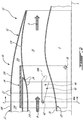
Fig. 2 is a schematic side cross-sectional view of part of a nacelle of an aircraft such as shown inFig. 1 , including a thrust reverser in accordance with a particular embodiment, the thrust reverser being in a closed configuration; -
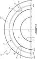
Fig. 3 is a schematic rear cross-sectional view of the nacelle with the thrust reverser in the closed configuration, taken along line 3-3 inFig. 2 ; -
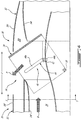
Fig. 4 is a schematic side cross-sectional view of the nacelle ofFigs. 2-3 , showing the thrust reverser in a deployed configuration; -
Fig. 5 is a schematic rear cross-sectional view of the nacelle with the thrust reverser in the deployed configuration, taken along line 5-5 inFig. 4 ; -
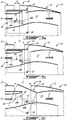
Figs. 6a-6c are schematic side cross-sectional views of the nacelle ofFigs. 2-5 , showing successive configurations of the thrust reverser intermediate the closed and deployed configurations; -
Fig. 7 is a schematic side cross-sectional view of part of another nacelle of an aircraft such as shown inFig. 1 , including a thrust reverser in accordance with another particular embodiment, the thrust reverser being in a closed configuration; -
Fig. 8 is a schematic rear cross-sectional view of the nacelle ofFig. 7 with the thrust reverser in the closed configuration, taken along line 8-8; and -
Fig. 9 is a schematic side cross-sectional view of the nacelle ofFigs. 7-8 , showing the thrust reverser in a deployed configuration. - In the drawings, embodiments of the invention are illustrated by way of example. It is to be expressly understood that the description and drawings are only for purposes of illustration and as an aid to understanding. They are not intended to be a definition of the limits of the invention.
- Referring to the drawings and more particularly to
Fig. 1 , an aircraft is shown at 1, and is generally described to illustrate some components for reference purposes in the present disclosure. Theaircraft 1 has a fuselage 2 having a fore end at which a cockpit is located, and an aft end supporting a tail assembly, with the cabin generally located between the cockpit and the tail assembly. The tail assembly comprises avertical stabilizer 3 with a rudder, andhorizontal stabilizers 4 with elevators. The tail assembly has a fuselage-mounted tail, but other configurations may also be used for theaircraft 1, such as cruciform, T-tail, etc.Wings 5 project laterally from the fuselage. Theaircraft 1 hasengines 6 contained innacelles wings 5, although thenacelles nacelle engine 6 and may also define air passages in communication with theengine 6. Although twoengines 6 are shown, it is understood that the aircraft 2 can have a single engine or more than two engines. - Referring to
Figs. 2-3 , anacelle 10 in accordance with a particular embodiment is partially shown. Thenacelle 10 includes anouter casing 12 which is annular and has a longitudinal axis L. Theouter casing 12 has an annularouter wall 14f which surrounds an upstream portion of anannular bypass passage 16 defined around the engine (not shown, but the location of which being identified at 6); thebypass passage 16 may be configured for example to receive a flow of air driven by a fan of the engine and bypassing the engine core, and mixed with the engine exhaust downstream of combustion. Theouter casing 12 also includes an annularexterior wall 18f radially outwardly spaced from theouter wall 14f so that acavity 20f is defined between theouter wall 14f and theexterior wall 18f. In a particular embodiment, theexterior wall 18f defines part of theouter surface 22 of thenacelle 10 exposed to the atmosphere. Theouter wall 14f defines anouter boundary 24 of thebypass passage 16 and is exposed to the bypass flow B circulating through thebypass passage 16. Aninner wall 26 of thebypass passage 16 is defined by an annularinner casing 28 located radially inwardly of theouter wall 14f. Theinner casing 28 separates the bypass flow B from theengine 6, so as to separate the bypass flow B from the main combustion flow. - In the embodiment shown, the
outer casing 12 is a fixed structure, i.e. it has a fixed position relative to theinner casing 28 and with respect to theengine 6. Theouter casing 12 andinner casing 28 may be interconnected through any suitable type of connection (not shown). - The
nacelle 10 includes athrust reverser 30 which is shown inFigs. 2-3 in a closed configuration and inFigs. 4-5 in a deployed configuration. In the deployed configuration, thethrust reverser 30 is configured to redirect a portion P of the bypass flow B toward the front of the nacelle 10 (left side ofFig. 4 ) so as to provide a reversed thrust to slow down the aircraft. Thethrust reverser 30 generally includes one or more translating cowl(s) 32 and one or more blocking panel(s) 34, one of each being shown in the Figures. In a particular embodiment and as can be best seen inFig. 3 , each translatingcowl 32 and each blockingpanel 34 extends around an arc of about 180 degrees; the other half of thenacelle 10 not shown in the Figure is a mirror image of the portion shown, so that thethrust reverser 30 includes two translatingcowls 32 and two blockingpanels 34. It is understood that alternately thethrust reverser 30 may include a single translatingcowl 32 and/or asingle blocking panel 34, or more than two translatingcowls 32 and/or blockingpanels 34, each spanning across a respective arc of thenacelle 10 sufficient to provide a desired reversed thrust when deployed. - The translating
cowl 32 has an arcuateouter wall 14t which surrounds a downstream portion of thebypass passage 16. The translatingcowl 32 also includes anarcuate exterior wall 18t concentric with and radially outwardly spaced from theouter wall 14t so that acavity 20t is defined between theouter wall 14t and theexterior wall 18t. The translatingcowl 32 is movable along the longitudinal axis L between a closed position (Figs. 2-3 ) and an open position (Fig. 4-5 ). In the closed position and as can be best seen inFig. 2 , the translatingcowl 32 abuts theouter casing 12, with theouter walls outer casing 12 and translatingcowl 32 cooperating to define a continuousouter boundary 24 of thebypass passage 16 exposed to the bypass flow B, and with theexterior walls outer casing 12 and translatingcowl 32 cooperating to define a continuousouter surface 22 of thenacelle 10 exposed to atmosphere. - In the open position and as can be best seen in
Fig. 4 , the translatingcowl 32 is axially spaced from theouter casing 12 so as to define anopening 36 therebetween, created by the space between theouter walls exterior walls bypass passage 16 and thenacelle 10 through theopening 36. Although not shown, it is understood that suitable vanes (for example, extending rearwardly from theouter casing 12 and received in thecavity 20t of the translatingcowl 32 when the translatingcowl 32 is in the closed position) can be provided across theopening 36, so as to help direct the flow toward the front of thenacelle 10. - The blocking
panel 34 is connected to theouter casing 12 by apivot connection 38. In the embodiment shown, thepivot connection 38 is defined at the rear end of the blockingpanel 34. As can be best seen inFigs. 3 and5 , in the embodiment shown thepivot connection 38 includes two spaced apart pivots 38' defining a pivot axis A orthogonal to the longitudinal axis L; it is understood that altemately, a single pivot or more than two pivots can be provided, for example depending on the size of the blockingpanel 34. The pivot connection 38 (e.g., pivots 38') is located radially outwardly of theouter walls bypass passage 16. The pivot connection 38 (e.g., pivots 38') is also located radially inwardly of theexterior walls cavity outer casing 12 and/or of the translatingcowl 32. - The blocking
panel 34 is pivotable about thepivot connection 38 between a stowed position (Figs. 2-3 ) and a pivoted position (Figs. 4-5 ). In the embodiment shown, in the stowed position and as can be best seen inFig. 3 , the blockingpanel 34 is located radially outwardly of theouter walls bypass passage 16. The blockingpanel 34 is also located radially inwardly of theexterior walls cavity outer casing 12 and/or of the translatingcowl 32. As can be best seen inFig. 2 , in the embodiment shown, the blockingpanel 34 extends in part within thecavity 20t of the translatingcowl 32 and in part within thecavity 20f of theouter casing 12 when the blockingpanel 34 is in the stowed position and the translatingcowl 32 is in the closed position; in other words, the blockingpanel 34 extends in part within the translatingcowl 32 and in part within theouter casing 12 when thethrust reverser 30 is in the closed configuration. - In the pivoted position and as can be best seen in
Fig. 4 , the blockingpanel 34 extends within thebypass passage 16 adjacent theopening 36 to direct at least a portion P of the bypass flow B toward and out of theopening 36. In the embodiment shown, the blockingpanel 34 in the pivoted position is angled so that its forward end is located radially outwardly of its rear end, and the blockingpanel 34 protrudes through theopening 36, i.e. part of the blockingpanel 34 extends radially outwardly of at least theouter walls exterior walls - As can be best seen in
Figs. 2 and4 , the blockingpanel 34 is also connected to the translatingcowl 32, by a slidingconnection 40 including anengagement member 42 slidingly engaged in atrack 44. It is understood that the term "track" as used herein is intended to encompass any suitable structure allowing to slidingly receive and guide a sliding movement of a complementary engagement member, including, but not limited to, a slot defined in a structure configured to slidingly receive and guide the complementary engagement member, and two spaced apart rails protruding from a structure with the space between the rails being configured to slidingly receive and guide the complementary engagement member. In a particular embodiment, the engagement member is a spigot; it is however understood that the engagement member may have any suitable shape. - The
pivot connection 38 is located aft of thetrack 44 when the blockingpanel 34 is in the stowed position. In the embodiment shown, the slidingconnection 40 includes twotracks 44 and twoengagement members 42; eachtrack 44 is connected to the blockingpanel 34 and eachengagement member 42 protrudes from the translatingcowl 32. As can be best seen inFigs. 3 and5 , in the embodiment shown thetracks 44 are circumferentially spaced from each other, and circumferentially located between the two pivots 38'. Other configurations are also possible. - Referring back to
Figs. 2 and4 , it can be seen that thetrack 44 has afirst portion 44a parallel to the longitudinal axis L and asecond portion 44b non-parallel to the longitudinal axis L. In the embodiment shown, thesecond portion 44b extends from thefirst portion 44a toward the longitudinal axis L, and is located rearwardly of thefirst portion 44a. Theengagement member 42 is received in thefirst portion 44a of the track when thethrust reverser 30 is in the closed configuration (Figs. 2-3 ) and in thesecond portion 44b of the track when thethrust reverser 30 is in the deployed configuration (Figs. 4-5 ). - In use, the configuration of the
thrust reverser 30 is changed through the sliding motion of the translatingcowl 32, which may be driven by any suitable type of actuation mechanism (not shown), including, but not limited to, linearly extending hydraulic actuators. The sliding motion of the translatingcowl 32 causes the pivoting motion of the blockingpanel 34 about thepivot connection 38 due to the slidingconnection 40, which is configured so that the translatingcowl 32 causes pivoting of the blockingpanel 34 during only part of the motion of the translatingcowl 32, as described in the following. -
Figs. 6a to 6c show thethrust reverser 30 in successive intermediate configurations between the closed configuration ofFig. 2 and the deployed configuration ofFig. 5 , representing for example the position of the translatingcowl 32 and of the blockingpanel 34 when the translatingcowl 32 is located at 25% (Fig. 6a ), 50% (Fig. 6b ) and 75% (Fig. 6c ) of its maximum distance d (Fig. 4 ) from theouter casing 12, i.e. d1 (Fig. 6a ) = 0,25d, d2 (Fig. 6b ) = 0.5d and d3 (Fig. 6c ) = 0,75d; other values are also possible. The motion of the translatingcowl 32 along the longitudinal axis L slides theengagement member 42 within thetrack 44. It can be seen from the comparison ofFigs. 2 ,6a and 6b that the motion of the translatingcowl 32 is performed without moving the blockingpanel 34 when theengagement member 42 slides within the first,longitudinal portion 44a of thetrack 44, i.e. the blockingpanel 34 remains in the stowed position. Between a predetermined intermediate configuration where theengagement member 42 is at the junction of the first andsecond portions Fig. 6b ) and the deployed configuration, as can be seen from the comparison ofFigs. 6b, 6c and4 , the motion of the translatingcowl 32 causes the blockingpanel 34 to pivot about thepivot connection 40 between the stowed and pivoted positions when theengagement member 42 slides within the second,angled portion 44b of thetrack 44. The pivoting motion of the blockingpanel 34 is guided by the interaction between theengagement member 42 and the walls of thetrack 44. Theengagement member 42 slides in thesecond portion 44b of thetrack 44 first toward the end of thetrack 44, i.e. away from thefirst portion 44a, and then back toward thefirst portion 44a, while remaining within thesecond portion 44b, as the blockingpanel 34 pivots from the stowed to the pivoted positions. - Referring to
Figs. 7-9 , anacelle 110 according to another embodiment is generally shown, where elements similar to that of thenacelle 10 ofFigs. 2-6c are identified by the same reference numerals and will not be further described herein. Thenacelle 110 differs from the previously shown and describednacelle 10 in that thetrack 144 of the slidingconnection 140 is connected to the translatingcowl 32 and theengagement member 142 protrudes from the blockingpanel 34. Accordingly, thesecond portion 144b of thetrack 144 extends from thefirst portion 144a away from the longitudinal axis L, and is located in front of thefirst portion 144a. Similarly to thethrust reverser 30 described above, thethrust reverser 130 ofFigs. 7-9 is configurable between the closed configuration (Figs. 7-8 ) and the deployed configuration (Fig. 9 ) by the motion of the translatingcowl 32 along the longitudinal axis L, with the interaction between theengagement member 142 and thetrack 144 causing the blockingpanel 34 to remain in the stowed position between the closed configuration and an intermediate configuration as theengagement member 142 slides within the first,longitudinal portion 144a of thetrack 144, and to pivot about itspivot connection 38 with theouter casing 12 between the stowed and the pivoted positions as theengagement member 142 slides within the second,angled portion 144b of thetrack 144. - In a particular embodiment, the
thrust reverser cowl 32 away from theouter casing 12 along the longitudinal axis L of thecasing 12 until the translatingcowl 32 reaches the open position; this includes moving the translatingcowl 32 away from theouter casing 12 without moving the blockingpanel 34 relative to theouter casing 12 until the translatingcowl 32 reaches an intermediate position, with the blockingpanel 34 remaining radially outward of thebypass passage 16 and theengagement member track cowl 32 away from theouter casing 12 from the intermediate position to the open position to pivot the blockingpanel 34 about thepivot connection 38 by sliding theengagement member track panel 34 pivoting to the deployed position. The translatingcowl 32 moves rearwardly away from theouter casing 12 to reach the open position. - In a particular embodiment, the blocking
panel 34 is pivoted until it protrudes through theopening 36 between the translatingcowl 32 and theouter casing 12. - The sliding
connection cowl 32 and the blockingpanel 34 which allows a constant linear motion of the translatingcowl 32 while allowing the blockingpanel 34 to remain stationary during part of the linear motion of the translatingcowl 32 and to pivot during the remaining part of the linear motion of the translatingcowl 32. In a particular embodiment, the slidingconnection pivot connection 38 support the blockingpanel 34 while remaining at all times radially outward of theouter wall casing 12 and of thethrust reverser bypass passage 16. The blockingpanel 34 also remains outside of thebypass passage 16 when not deployed. Thethrust reverser - In a particular embodiment, the
thrust reverser connection - Modifications and improvements to the above-described embodiments of the present invention may become apparent to those skilled in the art. The foregoing description is intended to be exemplary rather than limiting. The scope of the present invention is therefore intended to be limited solely by the scope of the appended claims.
Claims (14)
- A nacelle (10, 110) for an aircraft (1), comprising:an outer casing (12) having a longitudinal axis (L);a thrust reverser (30) including:a translating cowl (32), the outer casing and translating cowl cooperating to define an outer boundary (24) of a bypass passage (16) configured to surround an engine (6), the translating cowl movable relative to the outer casing along the longitudinal axis between a closed position and an open position, the translating cowl in the open position being axially spaced from the outer casing so as to define an opening (36) between the translating cowl and the outer casing; anda blocking panel (34) pivotable about a pivot connection (38) between;a stowed position, in which the blocking panel is located radially outwardly of the bypass passage; anda pivoted position, the blocking panel in the pivoted position extending within the bypass passage adjacent the opening to direct a flow toward the opening;wherein the blocking panel is connected to the translating cowl by a sliding connection (40) including an engagement member (42) slidingly engaged in a track (44), the track having a first portion (44a) parallel to the longitudinal axis and a second portion (44b) non-parallel to the longitudinal axis;wherein motion of the translating cowl along the longitudinal axis slides the engagement member within the track, the motion of the translating cowl being performed without moving the blocking panel when the engagement member is within the first portion of the track, the motion of the translating cowl causing the blocking panel to pivot about the pivot connection when the engagement member is within the second portion of the track.
- The nacelle (10, 110) as defined in claim 1, wherein the translating cowl (32) abuts the outer casing (12) when in the closed position.
- The nacelle (10, 110) as defined in claim 1 or 2, wherein the blocking panel (34) is connected to the outer casing (12) by the pivot connection (38).
- The nacelle (10, 110) as defined in claim 1, wherein the blocking panel (34) extends in part within the translating cowl (32) and in part within the outer casing (12) when the blocking panel is in the stowed position and the translating cowl is in the closed position.
- The nacelle (10, 110) as defined in any one of claims 1 to 4, wherein the track (44) is connected to the blocking panel (34) and the engagement member (42) protrudes from the translating cowl (32), the second portion (44b) of the track extending from the first portion (44a) toward the longitudinal axis (L).
- The nacelle (10, 110) as defined in any one of claims 1 to 4, wherein the track (44) is connected to the translating cowl (32) and the engagement member (42) protrudes from the blocking panel (34), the second portion (44b) of the track extending from the first portion (44a) away from the longitudinal axis (L).
- The nacelle (10, 110) as defined in any one of claims 1 to 6, wherein the blocking panel (32) is arcuate, the pivot connection (38) including two circumferentially spaced pivots (38') defining a pivot axis (A) orthogonal to the longitudinal axis (L), the sliding connection (40) being positioned circumferentially between the two pivots.
- The nacelle (10, 110) as defined in any one of claims 1 to 7, wherein the pivot connection (38) is located radially outwardly of the bypass passage (16).
- The nacelle (10, 110) as defined in any one of claims 1 to 8, wherein the pivot connection (38) is located aft of the track (44) when the blocking panel (34) is in the stowed position.
- The nacelle (10, 110) as defined in any one of claims 1 to 9, wherein the blocking panel (34) protrudes through the opening (36) when the blocking panel is in the pivoted position.
- The nacelle (10, 110) as defined in any one of claims 1 to 10, wherein the blocking panel (34) includes a forward end and a rear end, the forward end being located radially outwardly of the rear end when the blocking panel is in the pivoted position.
- A method of deploying a thrust reverser (30) for an aircraft engine (6), the thrust reverser including a translating cowl (3") and a blocking panel (34) slidingly interconnected by an engagement member (42) received in a track (44), the method comprising:
moving the translating cowl away from an outer casing (12) along a longitudinal axis (L) of the outer casing until the translating cowl reaches an open position, the outer casing and translating cowl defining an outer boundary (24) of a bypass passage (16) surrounding the engine, wherein moving the translating cowl includes:moving the translating cowl away from the outer casing without moving the blocking panel relative to the outer casing until the translating cowl reaches an intermediate position and while the engagement member slides in a first portion (44a) of the track parallel to the longitudinal axis; andmoving the translating cowl away from the outer casing from the intermediate position to the open position to pivot the blocking panel by sliding the engagement member in a second portion (44b) of the track non-parallel to the longitudinal axis, the blocking panel pivoting from a position located radially outwardly of the bypass passage to a position where the blocking panel extends within the bypass passage to direct a flow radially outwardly toward an opening (36) between the translating cowl and the outer casing. - The method as defined in claim 12, wherein the blocking panel (34) pivots about a pivot connection (38) located radially outwardly of the bypass passage (16).
- The method as defined in claim 13, wherein the translating cowl (32) moves rearwardly away from the outer casing (12), and the pivot connection (38) is located on a rear end of the blocking panel (34).
Applications Claiming Priority (2)
| Application Number | Priority Date | Filing Date | Title |
|---|---|---|---|
| GB1712056.9A GB2564891A (en) | 2017-07-26 | 2017-07-26 | Nacelle with thrust reverser |
| PCT/GB2018/052089 WO2019020995A1 (en) | 2017-07-26 | 2018-07-25 | Nacelle with thrust reverser |
Publications (2)
| Publication Number | Publication Date |
|---|---|
| EP3658761A1 EP3658761A1 (en) | 2020-06-03 |
| EP3658761B1 true EP3658761B1 (en) | 2021-12-01 |
Family
ID=59771716
Family Applications (1)
| Application Number | Title | Priority Date | Filing Date |
|---|---|---|---|
| EP18752206.5A Not-in-force EP3658761B1 (en) | 2017-07-26 | 2018-07-25 | Nacelle with thrust reverser |
Country Status (6)
| Country | Link |
|---|---|
| US (1) | US11230994B2 (en) |
| EP (1) | EP3658761B1 (en) |
| CN (1) | CN110945228A (en) |
| CA (1) | CA3070198A1 (en) |
| GB (1) | GB2564891A (en) |
| WO (1) | WO2019020995A1 (en) |
Families Citing this family (2)
| Publication number | Priority date | Publication date | Assignee | Title |
|---|---|---|---|---|
| TW202535949A (en) | 2023-12-20 | 2025-09-16 | 美商必治妥美雅史谷比公司 | Antibodies targeting il-18 receptor beta (il-18rβ) and related methods |
| US20250297556A1 (en) * | 2024-03-19 | 2025-09-25 | Pratt & Whitney Canada Corp. | Aircraft powerplant with joint shield |
Family Cites Families (30)
| Publication number | Priority date | Publication date | Assignee | Title |
|---|---|---|---|---|
| FR2111726B1 (en) * | 1970-10-20 | 1976-02-13 | Secretaire Etat R Uni Gb | |
| US5103634A (en) | 1988-06-10 | 1992-04-14 | The Boeing Company | Thrust reversing system and method |
| US5197693A (en) * | 1991-08-15 | 1993-03-30 | Rohr, Inc. | Aircraft turbine engine thrust reverser with sliding hinge actuator |
| FR2752017B1 (en) * | 1996-08-01 | 1998-10-16 | Hispano Suiza Sa | TURBOREACTOR DRIVE INVERTER WITH SCOOPING DOORS |
| EP0852290A1 (en) * | 1996-12-19 | 1998-07-08 | SOCIETE DE CONSTRUCTION DES AVIONS HUREL-DUBOIS (société anonyme) | Thrust reverser for high bypass fan engine |
| FR2764339B1 (en) * | 1997-06-05 | 1999-07-16 | Hispano Suiza Sa | TURBOREACTOR DRIVE INVERTER WITH SCOOPING DOORS ASSOCIATED WITH A MOBILE UPSTREAM CAP |
| FR2776023B1 (en) * | 1998-03-12 | 2000-04-07 | Hispano Suiza Sa | TURBOREACTOR DRIVE INVERTER WITH SCOOPING DOORS ASSOCIATED WITH A MOBILE GRID |
| FR2777043B1 (en) * | 1998-04-02 | 2000-05-12 | Hispano Suiza Sa | TURBORATORY DRIVE INVERTER WITH SCOOPING DOORS ASSOCIATED WITH AN ARTICULATED EXTERNAL COVER |
| FR2780101B1 (en) * | 1998-06-18 | 2000-07-28 | Hispano Suiza Sa | TURBOREACTOR DRIVE INVERTER WITH SCOOPING DOORS WITH ADAPTABLE EXHAUST SECTION |
| BR0315201A (en) * | 2002-10-11 | 2005-08-16 | Nordam Group Inc | Double Fold Boost Inverter |
| FR2907170B1 (en) * | 2006-10-11 | 2008-12-12 | Aircelle Sa | THRUST INVERTER WITH GRIDS FOR REACTION ENGINE |
| FR2933144B1 (en) | 2008-06-26 | 2012-08-17 | Airbus France | NACELLE FOR AN AIRCRAFT COMPRISING INVERTER PUSHING MEANS AND AIRCRAFT COMPRISING AT LEAST ONE SUCH NACELLE |
| FR2946696B1 (en) * | 2009-06-10 | 2012-04-20 | Aircelle Sa | PUSH REVERSING DEVICE |
| FR2966883B1 (en) | 2010-11-03 | 2012-11-02 | Aircelle Sa | INVERSION DEVICE FOR PUSHING WITHOUT BUCKLE IN THE VEIN |
| FR2978991A1 (en) | 2011-08-08 | 2013-02-15 | Snecma | THRUST INVERSION DEVICE FOR COMPACT PIPE |
| US9631578B2 (en) * | 2013-02-22 | 2017-04-25 | United Technologies Corporation | Pivot thrust reverser surrounding inner surface of bypass duct |
| US9447749B2 (en) * | 2013-04-02 | 2016-09-20 | Rohr, Inc. | Pivoting blocker door for thrust reverser |
| US9518534B2 (en) | 2013-06-19 | 2016-12-13 | Rohr, Inc. | Reverse scissor thrust reverser for a turbine engine |
| FR3007800B1 (en) | 2013-07-01 | 2017-10-20 | Aircelle Sa | THRUST INVERTER OF A TURBOJET NACELLE COMPRISING PARTIALLY INTEGRATED GRIDS IN HOODS |
| FR3008071B1 (en) * | 2013-07-04 | 2017-07-28 | Aircelle Sa | VANABLE TUBE TURBOBOREACTEUR NACELLE |
| EP3027876A1 (en) * | 2013-07-30 | 2016-06-08 | General Electric Company | Thrust reverser system with translating-rotating hinge assembly |
| FR3016006A1 (en) * | 2014-01-02 | 2015-07-03 | Aircelle Sa | TURBOREACTOR NACELLE PUSH INVERTER COMPRISING SLIDING AND SWIVELING GRIDS |
| US9534562B2 (en) | 2014-04-25 | 2017-01-03 | Rohr, Inc. | System and apparatus for a thrust reverser |
| US10309343B2 (en) | 2014-11-06 | 2019-06-04 | Rohr, Inc. | Split sleeve hidden door thrust reverser |
| US10208708B2 (en) | 2015-01-29 | 2019-02-19 | Rohr, Inc. | Translating cascade hidden blocker door thrust reverser |
| US20160305370A1 (en) * | 2015-04-16 | 2016-10-20 | Honeywell International Inc. | Translating cowl thrust reverser with door pivots aft of reverse flow path |
| US9915226B2 (en) | 2015-06-18 | 2018-03-13 | Rohr, Inc. | Variable area fan nozzle hidden blocker door thrust reverser |
| US20170204808A1 (en) * | 2016-01-18 | 2017-07-20 | Honeywell International Inc. | Translating cowl thrust reverser having a pressure imbalance that reduces overall structural load |
| US10655564B2 (en) * | 2016-05-13 | 2020-05-19 | Rohr, Inc. | Thrust reverser system with hidden blocker doors |
| US10415503B2 (en) * | 2017-03-10 | 2019-09-17 | Spirit Aerosystems, Inc. | Cascade pivot door-type thrust reverser for turbofan engine |
-
2017
- 2017-07-26 GB GB1712056.9A patent/GB2564891A/en not_active Withdrawn
-
2018
- 2018-07-25 US US16/632,780 patent/US11230994B2/en not_active Expired - Fee Related
- 2018-07-25 CA CA3070198A patent/CA3070198A1/en active Pending
- 2018-07-25 EP EP18752206.5A patent/EP3658761B1/en not_active Not-in-force
- 2018-07-25 WO PCT/GB2018/052089 patent/WO2019020995A1/en not_active Ceased
- 2018-07-25 CN CN201880049880.8A patent/CN110945228A/en active Pending
Also Published As
| Publication number | Publication date |
|---|---|
| EP3658761A1 (en) | 2020-06-03 |
| CA3070198A1 (en) | 2019-01-31 |
| CN110945228A (en) | 2020-03-31 |
| US20210156338A1 (en) | 2021-05-27 |
| US11230994B2 (en) | 2022-01-25 |
| GB2564891A (en) | 2019-01-30 |
| WO2019020995A1 (en) | 2019-01-31 |
| GB201712056D0 (en) | 2017-09-06 |
Similar Documents
| Publication | Publication Date | Title |
|---|---|---|
| EP2459862B1 (en) | Integrated thrust reverser assembly | |
| EP3244051B1 (en) | Gas turbine engine with thrust reverser assembly and method of operating | |
| US8402765B2 (en) | Translating variable area fan nozzle providing an upstream bypass flow exit | |
| EP1462642B1 (en) | Thrust reverser utilizing integrated structural bypass duct | |
| US9551298B2 (en) | Variable area fan nozzle with one or more integrated blocker doors | |
| US9759087B2 (en) | Translating variable area fan nozzle providing an upstream bypass flow exit | |
| EP3452713B1 (en) | Thrust reverser assembly | |
| US20210108594A1 (en) | Thrust reverser assembly and method of operating | |
| EP2278147B1 (en) | Translating variable area fan nozzle providing an upstream bypass flow exit | |
| EP2987991B1 (en) | Fan nozzle with thrust reversing and variable area function | |
| CN113692381A (en) | Nacelle for a dual-ducted turbine comprising a thrust reverser, dual-ducted turbine comprising such a nacelle, and aircraft comprising at least one such turbine | |
| EP3658761B1 (en) | Nacelle with thrust reverser | |
| US20150260125A1 (en) | Synchronization system for a thrust reverser | |
| US4313581A (en) | Reverser door mechanisms | |
| US20260055742A1 (en) | Latches for nacelle inner structure sections | |
| CN114051557A (en) | Movable cowl thrust reverser including a thrust reducing mechanism independent of the movable cowl |
Legal Events
| Date | Code | Title | Description |
|---|---|---|---|
| STAA | Information on the status of an ep patent application or granted ep patent |
Free format text: STATUS: UNKNOWN |
|
| STAA | Information on the status of an ep patent application or granted ep patent |
Free format text: STATUS: THE INTERNATIONAL PUBLICATION HAS BEEN MADE |
|
| PUAI | Public reference made under article 153(3) epc to a published international application that has entered the european phase |
Free format text: ORIGINAL CODE: 0009012 |
|
| STAA | Information on the status of an ep patent application or granted ep patent |
Free format text: STATUS: REQUEST FOR EXAMINATION WAS MADE |
|
| 17P | Request for examination filed |
Effective date: 20200123 |
|
| AK | Designated contracting states |
Kind code of ref document: A1 Designated state(s): AL AT BE BG CH CY CZ DE DK EE ES FI FR GB GR HR HU IE IS IT LI LT LU LV MC MK MT NL NO PL PT RO RS SE SI SK SM TR |
|
| AX | Request for extension of the european patent |
Extension state: BA ME |
|
| DAV | Request for validation of the european patent (deleted) | ||
| DAX | Request for extension of the european patent (deleted) | ||
| STAA | Information on the status of an ep patent application or granted ep patent |
Free format text: STATUS: EXAMINATION IS IN PROGRESS |
|
| 17Q | First examination report despatched |
Effective date: 20201210 |
|
| GRAP | Despatch of communication of intention to grant a patent |
Free format text: ORIGINAL CODE: EPIDOSNIGR1 |
|
| STAA | Information on the status of an ep patent application or granted ep patent |
Free format text: STATUS: GRANT OF PATENT IS INTENDED |
|
| INTG | Intention to grant announced |
Effective date: 20210621 |
|
| GRAS | Grant fee paid |
Free format text: ORIGINAL CODE: EPIDOSNIGR3 |
|
| GRAA | (expected) grant |
Free format text: ORIGINAL CODE: 0009210 |
|
| STAA | Information on the status of an ep patent application or granted ep patent |
Free format text: STATUS: THE PATENT HAS BEEN GRANTED |
|
| AK | Designated contracting states |
Kind code of ref document: B1 Designated state(s): AL AT BE BG CH CY CZ DE DK EE ES FI FR GB GR HR HU IE IS IT LI LT LU LV MC MK MT NL NO PL PT RO RS SE SI SK SM TR |
|
| REG | Reference to a national code |
Ref country code: GB Ref legal event code: FG4D |
|
| REG | Reference to a national code |
Ref country code: AT Ref legal event code: REF Ref document number: 1451977 Country of ref document: AT Kind code of ref document: T Effective date: 20211215 Ref country code: CH Ref legal event code: EP |
|
| REG | Reference to a national code |
Ref country code: IE Ref legal event code: FG4D |
|
| REG | Reference to a national code |
Ref country code: DE Ref legal event code: R096 Ref document number: 602018027528 Country of ref document: DE |
|
| REG | Reference to a national code |
Ref country code: LT Ref legal event code: MG9D |
|
| REG | Reference to a national code |
Ref country code: NL Ref legal event code: MP Effective date: 20211201 |
|
| REG | Reference to a national code |
Ref country code: AT Ref legal event code: MK05 Ref document number: 1451977 Country of ref document: AT Kind code of ref document: T Effective date: 20211201 |
|
| PG25 | Lapsed in a contracting state [announced via postgrant information from national office to epo] |
Ref country code: RS Free format text: LAPSE BECAUSE OF FAILURE TO SUBMIT A TRANSLATION OF THE DESCRIPTION OR TO PAY THE FEE WITHIN THE PRESCRIBED TIME-LIMIT Effective date: 20211201 Ref country code: LT Free format text: LAPSE BECAUSE OF FAILURE TO SUBMIT A TRANSLATION OF THE DESCRIPTION OR TO PAY THE FEE WITHIN THE PRESCRIBED TIME-LIMIT Effective date: 20211201 Ref country code: FI Free format text: LAPSE BECAUSE OF FAILURE TO SUBMIT A TRANSLATION OF THE DESCRIPTION OR TO PAY THE FEE WITHIN THE PRESCRIBED TIME-LIMIT Effective date: 20211201 Ref country code: BG Free format text: LAPSE BECAUSE OF FAILURE TO SUBMIT A TRANSLATION OF THE DESCRIPTION OR TO PAY THE FEE WITHIN THE PRESCRIBED TIME-LIMIT Effective date: 20220301 Ref country code: AT Free format text: LAPSE BECAUSE OF FAILURE TO SUBMIT A TRANSLATION OF THE DESCRIPTION OR TO PAY THE FEE WITHIN THE PRESCRIBED TIME-LIMIT Effective date: 20211201 |
|
| PG25 | Lapsed in a contracting state [announced via postgrant information from national office to epo] |
Ref country code: SE Free format text: LAPSE BECAUSE OF FAILURE TO SUBMIT A TRANSLATION OF THE DESCRIPTION OR TO PAY THE FEE WITHIN THE PRESCRIBED TIME-LIMIT Effective date: 20211201 Ref country code: PL Free format text: LAPSE BECAUSE OF FAILURE TO SUBMIT A TRANSLATION OF THE DESCRIPTION OR TO PAY THE FEE WITHIN THE PRESCRIBED TIME-LIMIT Effective date: 20211201 Ref country code: NO Free format text: LAPSE BECAUSE OF FAILURE TO SUBMIT A TRANSLATION OF THE DESCRIPTION OR TO PAY THE FEE WITHIN THE PRESCRIBED TIME-LIMIT Effective date: 20220301 Ref country code: LV Free format text: LAPSE BECAUSE OF FAILURE TO SUBMIT A TRANSLATION OF THE DESCRIPTION OR TO PAY THE FEE WITHIN THE PRESCRIBED TIME-LIMIT Effective date: 20211201 Ref country code: HR Free format text: LAPSE BECAUSE OF FAILURE TO SUBMIT A TRANSLATION OF THE DESCRIPTION OR TO PAY THE FEE WITHIN THE PRESCRIBED TIME-LIMIT Effective date: 20211201 Ref country code: GR Free format text: LAPSE BECAUSE OF FAILURE TO SUBMIT A TRANSLATION OF THE DESCRIPTION OR TO PAY THE FEE WITHIN THE PRESCRIBED TIME-LIMIT Effective date: 20220302 Ref country code: ES Free format text: LAPSE BECAUSE OF FAILURE TO SUBMIT A TRANSLATION OF THE DESCRIPTION OR TO PAY THE FEE WITHIN THE PRESCRIBED TIME-LIMIT Effective date: 20211201 |
|
| PG25 | Lapsed in a contracting state [announced via postgrant information from national office to epo] |
Ref country code: NL Free format text: LAPSE BECAUSE OF FAILURE TO SUBMIT A TRANSLATION OF THE DESCRIPTION OR TO PAY THE FEE WITHIN THE PRESCRIBED TIME-LIMIT Effective date: 20211201 |
|
| PG25 | Lapsed in a contracting state [announced via postgrant information from national office to epo] |
Ref country code: SM Free format text: LAPSE BECAUSE OF FAILURE TO SUBMIT A TRANSLATION OF THE DESCRIPTION OR TO PAY THE FEE WITHIN THE PRESCRIBED TIME-LIMIT Effective date: 20211201 Ref country code: SK Free format text: LAPSE BECAUSE OF FAILURE TO SUBMIT A TRANSLATION OF THE DESCRIPTION OR TO PAY THE FEE WITHIN THE PRESCRIBED TIME-LIMIT Effective date: 20211201 Ref country code: RO Free format text: LAPSE BECAUSE OF FAILURE TO SUBMIT A TRANSLATION OF THE DESCRIPTION OR TO PAY THE FEE WITHIN THE PRESCRIBED TIME-LIMIT Effective date: 20211201 Ref country code: PT Free format text: LAPSE BECAUSE OF FAILURE TO SUBMIT A TRANSLATION OF THE DESCRIPTION OR TO PAY THE FEE WITHIN THE PRESCRIBED TIME-LIMIT Effective date: 20220401 Ref country code: EE Free format text: LAPSE BECAUSE OF FAILURE TO SUBMIT A TRANSLATION OF THE DESCRIPTION OR TO PAY THE FEE WITHIN THE PRESCRIBED TIME-LIMIT Effective date: 20211201 Ref country code: CZ Free format text: LAPSE BECAUSE OF FAILURE TO SUBMIT A TRANSLATION OF THE DESCRIPTION OR TO PAY THE FEE WITHIN THE PRESCRIBED TIME-LIMIT Effective date: 20211201 |
|
| REG | Reference to a national code |
Ref country code: DE Ref legal event code: R097 Ref document number: 602018027528 Country of ref document: DE |
|
| PG25 | Lapsed in a contracting state [announced via postgrant information from national office to epo] |
Ref country code: IS Free format text: LAPSE BECAUSE OF FAILURE TO SUBMIT A TRANSLATION OF THE DESCRIPTION OR TO PAY THE FEE WITHIN THE PRESCRIBED TIME-LIMIT Effective date: 20220401 |
|
| PLBE | No opposition filed within time limit |
Free format text: ORIGINAL CODE: 0009261 |
|
| STAA | Information on the status of an ep patent application or granted ep patent |
Free format text: STATUS: NO OPPOSITION FILED WITHIN TIME LIMIT |
|
| PG25 | Lapsed in a contracting state [announced via postgrant information from national office to epo] |
Ref country code: DK Free format text: LAPSE BECAUSE OF FAILURE TO SUBMIT A TRANSLATION OF THE DESCRIPTION OR TO PAY THE FEE WITHIN THE PRESCRIBED TIME-LIMIT Effective date: 20211201 Ref country code: AL Free format text: LAPSE BECAUSE OF FAILURE TO SUBMIT A TRANSLATION OF THE DESCRIPTION OR TO PAY THE FEE WITHIN THE PRESCRIBED TIME-LIMIT Effective date: 20211201 |
|
| 26N | No opposition filed |
Effective date: 20220902 |
|
| PG25 | Lapsed in a contracting state [announced via postgrant information from national office to epo] |
Ref country code: SI Free format text: LAPSE BECAUSE OF FAILURE TO SUBMIT A TRANSLATION OF THE DESCRIPTION OR TO PAY THE FEE WITHIN THE PRESCRIBED TIME-LIMIT Effective date: 20211201 |
|
| PG25 | Lapsed in a contracting state [announced via postgrant information from national office to epo] |
Ref country code: MC Free format text: LAPSE BECAUSE OF FAILURE TO SUBMIT A TRANSLATION OF THE DESCRIPTION OR TO PAY THE FEE WITHIN THE PRESCRIBED TIME-LIMIT Effective date: 20211201 |
|
| REG | Reference to a national code |
Ref country code: CH Ref legal event code: PL |
|
| REG | Reference to a national code |
Ref country code: BE Ref legal event code: MM Effective date: 20220731 |
|
| PG25 | Lapsed in a contracting state [announced via postgrant information from national office to epo] |
Ref country code: LU Free format text: LAPSE BECAUSE OF NON-PAYMENT OF DUE FEES Effective date: 20220725 Ref country code: LI Free format text: LAPSE BECAUSE OF NON-PAYMENT OF DUE FEES Effective date: 20220731 Ref country code: CH Free format text: LAPSE BECAUSE OF NON-PAYMENT OF DUE FEES Effective date: 20220731 |
|
| PG25 | Lapsed in a contracting state [announced via postgrant information from national office to epo] |
Ref country code: IT Free format text: LAPSE BECAUSE OF FAILURE TO SUBMIT A TRANSLATION OF THE DESCRIPTION OR TO PAY THE FEE WITHIN THE PRESCRIBED TIME-LIMIT Effective date: 20211201 Ref country code: BE Free format text: LAPSE BECAUSE OF NON-PAYMENT OF DUE FEES Effective date: 20220731 |
|
| PG25 | Lapsed in a contracting state [announced via postgrant information from national office to epo] |
Ref country code: IE Free format text: LAPSE BECAUSE OF NON-PAYMENT OF DUE FEES Effective date: 20220725 |
|
| PG25 | Lapsed in a contracting state [announced via postgrant information from national office to epo] |
Ref country code: MK Free format text: LAPSE BECAUSE OF FAILURE TO SUBMIT A TRANSLATION OF THE DESCRIPTION OR TO PAY THE FEE WITHIN THE PRESCRIBED TIME-LIMIT Effective date: 20211201 Ref country code: CY Free format text: LAPSE BECAUSE OF FAILURE TO SUBMIT A TRANSLATION OF THE DESCRIPTION OR TO PAY THE FEE WITHIN THE PRESCRIBED TIME-LIMIT Effective date: 20211201 |
|
| PG25 | Lapsed in a contracting state [announced via postgrant information from national office to epo] |
Ref country code: HU Free format text: LAPSE BECAUSE OF FAILURE TO SUBMIT A TRANSLATION OF THE DESCRIPTION OR TO PAY THE FEE WITHIN THE PRESCRIBED TIME-LIMIT; INVALID AB INITIO Effective date: 20180725 |
|
| PG25 | Lapsed in a contracting state [announced via postgrant information from national office to epo] |
Ref country code: MT Free format text: LAPSE BECAUSE OF FAILURE TO SUBMIT A TRANSLATION OF THE DESCRIPTION OR TO PAY THE FEE WITHIN THE PRESCRIBED TIME-LIMIT Effective date: 20211201 |
|
| PGFP | Annual fee paid to national office [announced via postgrant information from national office to epo] |
Ref country code: DE Payment date: 20240717 Year of fee payment: 7 |
|
| PGFP | Annual fee paid to national office [announced via postgrant information from national office to epo] |
Ref country code: GB Payment date: 20240704 Year of fee payment: 7 |
|
| PGFP | Annual fee paid to national office [announced via postgrant information from national office to epo] |
Ref country code: FR Payment date: 20240710 Year of fee payment: 7 |
|
| PG25 | Lapsed in a contracting state [announced via postgrant information from national office to epo] |
Ref country code: TR Free format text: LAPSE BECAUSE OF FAILURE TO SUBMIT A TRANSLATION OF THE DESCRIPTION OR TO PAY THE FEE WITHIN THE PRESCRIBED TIME-LIMIT Effective date: 20211201 |
|
| REG | Reference to a national code |
Ref country code: DE Ref legal event code: R119 Ref document number: 602018027528 Country of ref document: DE |
|
| GBPC | Gb: european patent ceased through non-payment of renewal fee |
Effective date: 20250725 |
|
| PG25 | Lapsed in a contracting state [announced via postgrant information from national office to epo] |
Ref country code: GB Free format text: LAPSE BECAUSE OF NON-PAYMENT OF DUE FEES Effective date: 20250725 |
|
| PG25 | Lapsed in a contracting state [announced via postgrant information from national office to epo] |
Ref country code: DE Free format text: LAPSE BECAUSE OF NON-PAYMENT OF DUE FEES Effective date: 20260203 |
|
| PG25 | Lapsed in a contracting state [announced via postgrant information from national office to epo] |
Ref country code: FR Free format text: LAPSE BECAUSE OF NON-PAYMENT OF DUE FEES Effective date: 20250731 |