EP3658759B1 - Combustor apparatus and method of operating combustor apparatus - Google Patents
Combustor apparatus and method of operating combustor apparatus Download PDFInfo
- Publication number
- EP3658759B1 EP3658759B1 EP18746645.3A EP18746645A EP3658759B1 EP 3658759 B1 EP3658759 B1 EP 3658759B1 EP 18746645 A EP18746645 A EP 18746645A EP 3658759 B1 EP3658759 B1 EP 3658759B1
- Authority
- EP
- European Patent Office
- Prior art keywords
- engine
- gas turbine
- helmholtz resonator
- turbine engine
- operating condition
- Prior art date
- Legal status (The legal status is an assumption and is not a legal conclusion. Google has not performed a legal analysis and makes no representation as to the accuracy of the status listed.)
- Active
Links
Images


Classifications
-
- F—MECHANICAL ENGINEERING; LIGHTING; HEATING; WEAPONS; BLASTING
- F01—MACHINES OR ENGINES IN GENERAL; ENGINE PLANTS IN GENERAL; STEAM ENGINES
- F01D—NON-POSITIVE DISPLACEMENT MACHINES OR ENGINES, e.g. STEAM TURBINES
- F01D25/00—Component parts, details, or accessories, not provided for in, or of interest apart from, other groups
- F01D25/04—Antivibration arrangements
-
- F—MECHANICAL ENGINEERING; LIGHTING; HEATING; WEAPONS; BLASTING
- F02—COMBUSTION ENGINES; HOT-GAS OR COMBUSTION-PRODUCT ENGINE PLANTS
- F02C—GAS-TURBINE PLANTS; AIR INTAKES FOR JET-PROPULSION PLANTS; CONTROLLING FUEL SUPPLY IN AIR-BREATHING JET-PROPULSION PLANTS
- F02C7/00—Features, components parts, details or accessories, not provided for in, or of interest apart form groups F02C1/00 - F02C6/00; Air intakes for jet-propulsion plants
- F02C7/04—Air intakes for gas-turbine plants or jet-propulsion plants
- F02C7/045—Air intakes for gas-turbine plants or jet-propulsion plants having provisions for noise suppression
-
- F—MECHANICAL ENGINEERING; LIGHTING; HEATING; WEAPONS; BLASTING
- F23—COMBUSTION APPARATUS; COMBUSTION PROCESSES
- F23M—CASINGS, LININGS, WALLS OR DOORS SPECIALLY ADAPTED FOR COMBUSTION CHAMBERS, e.g. FIREBRIDGES; DEVICES FOR DEFLECTING AIR, FLAMES OR COMBUSTION PRODUCTS IN COMBUSTION CHAMBERS; SAFETY ARRANGEMENTS SPECIALLY ADAPTED FOR COMBUSTION APPARATUS; DETAILS OF COMBUSTION CHAMBERS, NOT OTHERWISE PROVIDED FOR
- F23M20/00—Details of combustion chambers, not otherwise provided for, e.g. means for storing heat from flames
- F23M20/005—Noise absorbing means
-
- F—MECHANICAL ENGINEERING; LIGHTING; HEATING; WEAPONS; BLASTING
- F23—COMBUSTION APPARATUS; COMBUSTION PROCESSES
- F23R—GENERATING COMBUSTION PRODUCTS OF HIGH PRESSURE OR HIGH VELOCITY, e.g. GAS-TURBINE COMBUSTION CHAMBERS
- F23R3/00—Continuous combustion chambers using liquid or gaseous fuel
- F23R3/28—Continuous combustion chambers using liquid or gaseous fuel characterised by the fuel supply
- F23R3/286—Continuous combustion chambers using liquid or gaseous fuel characterised by the fuel supply having fuel-air premixing devices
-
- F—MECHANICAL ENGINEERING; LIGHTING; HEATING; WEAPONS; BLASTING
- F05—INDEXING SCHEMES RELATING TO ENGINES OR PUMPS IN VARIOUS SUBCLASSES OF CLASSES F01-F04
- F05B—INDEXING SCHEME RELATING TO WIND, SPRING, WEIGHT, INERTIA OR LIKE MOTORS, TO MACHINES OR ENGINES FOR LIQUIDS COVERED BY SUBCLASSES F03B, F03D AND F03G
- F05B2260/00—Function
- F05B2260/96—Preventing, counteracting or reducing vibration or noise
-
- F—MECHANICAL ENGINEERING; LIGHTING; HEATING; WEAPONS; BLASTING
- F05—INDEXING SCHEMES RELATING TO ENGINES OR PUMPS IN VARIOUS SUBCLASSES OF CLASSES F01-F04
- F05D—INDEXING SCHEME FOR ASPECTS RELATING TO NON-POSITIVE-DISPLACEMENT MACHINES OR ENGINES, GAS-TURBINES OR JET-PROPULSION PLANTS
- F05D2240/00—Components
- F05D2240/35—Combustors or associated equipment
-
- F—MECHANICAL ENGINEERING; LIGHTING; HEATING; WEAPONS; BLASTING
- F05—INDEXING SCHEMES RELATING TO ENGINES OR PUMPS IN VARIOUS SUBCLASSES OF CLASSES F01-F04
- F05D—INDEXING SCHEME FOR ASPECTS RELATING TO NON-POSITIVE-DISPLACEMENT MACHINES OR ENGINES, GAS-TURBINES OR JET-PROPULSION PLANTS
- F05D2260/00—Function
- F05D2260/20—Heat transfer, e.g. cooling
-
- F—MECHANICAL ENGINEERING; LIGHTING; HEATING; WEAPONS; BLASTING
- F05—INDEXING SCHEMES RELATING TO ENGINES OR PUMPS IN VARIOUS SUBCLASSES OF CLASSES F01-F04
- F05D—INDEXING SCHEME FOR ASPECTS RELATING TO NON-POSITIVE-DISPLACEMENT MACHINES OR ENGINES, GAS-TURBINES OR JET-PROPULSION PLANTS
- F05D2260/00—Function
- F05D2260/96—Preventing, counteracting or reducing vibration or noise
- F05D2260/963—Preventing, counteracting or reducing vibration or noise by Helmholtz resonators
-
- F—MECHANICAL ENGINEERING; LIGHTING; HEATING; WEAPONS; BLASTING
- F05—INDEXING SCHEMES RELATING TO ENGINES OR PUMPS IN VARIOUS SUBCLASSES OF CLASSES F01-F04
- F05D—INDEXING SCHEME FOR ASPECTS RELATING TO NON-POSITIVE-DISPLACEMENT MACHINES OR ENGINES, GAS-TURBINES OR JET-PROPULSION PLANTS
- F05D2260/00—Function
- F05D2260/96—Preventing, counteracting or reducing vibration or noise
- F05D2260/964—Preventing, counteracting or reducing vibration or noise counteracting thermoacoustic noise
-
- F—MECHANICAL ENGINEERING; LIGHTING; HEATING; WEAPONS; BLASTING
- F23—COMBUSTION APPARATUS; COMBUSTION PROCESSES
- F23R—GENERATING COMBUSTION PRODUCTS OF HIGH PRESSURE OR HIGH VELOCITY, e.g. GAS-TURBINE COMBUSTION CHAMBERS
- F23R2900/00—Special features of, or arrangements for continuous combustion chambers; Combustion processes therefor
- F23R2900/00013—Reducing thermo-acoustic vibrations by active means
-
- F—MECHANICAL ENGINEERING; LIGHTING; HEATING; WEAPONS; BLASTING
- F23—COMBUSTION APPARATUS; COMBUSTION PROCESSES
- F23R—GENERATING COMBUSTION PRODUCTS OF HIGH PRESSURE OR HIGH VELOCITY, e.g. GAS-TURBINE COMBUSTION CHAMBERS
- F23R2900/00—Special features of, or arrangements for continuous combustion chambers; Combustion processes therefor
- F23R2900/00014—Reducing thermo-acoustic vibrations by passive means, e.g. by Helmholtz resonators
-
- F—MECHANICAL ENGINEERING; LIGHTING; HEATING; WEAPONS; BLASTING
- F23—COMBUSTION APPARATUS; COMBUSTION PROCESSES
- F23R—GENERATING COMBUSTION PRODUCTS OF HIGH PRESSURE OR HIGH VELOCITY, e.g. GAS-TURBINE COMBUSTION CHAMBERS
- F23R3/00—Continuous combustion chambers using liquid or gaseous fuel
- F23R3/002—Wall structures
Definitions
- DLE combustion systems are known to be reliable in producing low NOx and having compact flames.
- most DLE combustion systems are prone to combustion dynamics, such as acoustic fluctuations, because they operate with a lean mixture of fuel and air in order to achieve low NOx emissions.
- Combustion dynamics can arise as a result of flame excitation, aerodynamic induced excitation or insufficient damping.
- WO2011/128,156 discloses a resonator device for damping a pressure oscillation within a combustion chamber, the resonator device comprising: a container filled with a gas; an opening in the container; and a heating element adapted to generate a flame. The flame is arranged to heat the gas within the container.
- the resonator device is comprised in a combustion arrangement, further comprising a combustion chamber for defining a combustion space for burning fuel.
- the container is connected to the combustion chamber such that an inside of the container is in communication with the combustion space via the opening.
- the resonator device has a resonance frequency equal to a pressure oscillation frequency within the combustion chamber under normal load conditions.
- EP1557 609 A1 discloses a Helmholtz resonator, which has a resonating volume in connection with the combustion chamber volume via a connective opening.
- the device has the unique characteristic that an adjustable flow of cooling air can be introduced into the resonating volume and connective opening.
- the present invention allows for the first time the resonance frequency of the Helmholtz resonator to be adjusted by a dynamic flow of cooling air.
- a method for damping thermoacoustic oscillations in a combustion chamber is also given, wherein a flow of cooling air is adjusted in order to modify the resonator characteristics of the Helmholtz resonator fluidically connected to the combustion chamber.
- One objective of the present combustion apparatus is to attenuate more than one frequency range of combustion acoustics. Another objective is to identify and damp or attenuate combustor acoustic amplitude peaks at different engine operating loads. Another objective is to automatically control the attenuation frequency of the Helmholtz resonator to match shifts of the combustion dynamics peaks. Another objective is to minimise parts count. Another objective is to extend the engine's operating envelope for dry low-emission operation and especially at part-load. Another objective is to prevent resonance in a bleed arrangement of the combustor and prevent undesirable combustion dynamics. In this way natural frequencies of the bleed arrangement can be prevented from causing destructive combustion dynamics and prevent combustion flame instability.
- a gas turbine engine comprising combustion apparatus defining a volume, a compressor, a cooling air supply feed from the compressor, a bleed arrangement comprising a conduit, the conduit is connected to the volume such that fluid can be bled from the volume through the conduit, a Helmholtz resonator.
- the Helmholtz resonator comprises a neck and a chamber having an attenuation volume and which is in fluid communication with the volume.
- the Helmholtz resonator is connected to the conduit such that fluid in the conduit can pass therebetween.
- the cooling air supply feed is connected to the Helmholtz resonator and comprises a valve arrangement.
- the valve arrangement is configured such that in a first engine operating condition the valve arrangement is closed and the Helmholtz resonator attenuates acoustic frequencies in a first range and in a second engine operating condition the valve arrangement is open whereby cooling air purges the attenuation volume and the Helmholtz resonator attenuates acoustic frequencies in a second range.
- the gas turbine engine further comprises a combustion dynamics probe configured to measure a temperature in the combustion apparatus and an engine control unit.
- the engine control unit is connected to the combustion dynamics probe and to the valve arrangement and is configured to command the valve arrangement to open and close depending on the temperature being measured by the combustion dynamics probe.
- the first engine operating condition may be at a different load output than the second engine operating condition.
- the first engine operating condition is at a higher output than the second engine operating condition.
- the Helmholtz resonator may be at a higher temperature than at the second engine operating condition.
- the gas turbine engine further comprises an engine control unit and a combustion dynamics probe associated with the combustion apparatus.
- the engine control unit is connected to the combustion dynamics probe and the valve arrangement to command the valve arrangement to open and close dependent on the acoustic frequency of the combustion apparatus.
- the gas turbine engine further comprises an annular combustor apparatus.
- the gas turbine engine further comprises an annular array of combustor apparatus each having at least one Helmholtz resonator.
- Each Helmholtz resonator may be connected to its own valve arrangement and opened or closed independently of the other valve arrangements.
- Each Helmholtz resonator may be connected to a single valve arrangement.
- the temperature In the first engine operating condition the temperature may be between 590K and 790K, preferably 640K and 730K or more preferably approximately 690K. In the second engine operating condition the temperature may be between 300K and 400K, preferably 325K and 375K and more preferably 350K.
- the engine In the first engine operating condition the engine may be operating at at least 90% of its maximum output. In the second engine operating condition the engine may be operating between 50% and 75% of its maximum output.
- the geometry of the neck and the chamber of the Helmholtz resonator may be set to attenuate acoustic frequencies in a first range.
- a method of operating a gas turbine engine comprising the steps of detecting a change in temperature in the combustion apparatus whereby the acoustic frequency to be attenuated at the first engine operating condition is outside the range of the Helmholtz resonator and opening the valve arrangement and supplying cooling air the Helmholtz resonator such that it attenuates acoustic frequencies in the second range.
- FIG. 1 shows an example of a gas turbine engine 10 in a sectional view.
- the gas turbine engine 10 comprises, in flow series, an inlet 12, a compressor or compressor section 14, a combustor section 16,a turbine section 18 and an exhaust duct (not shown) which are generally arranged in flow series and generally about and in the direction of a longitudinal or rotational axis 20.
- the gas turbine engine 10 further comprises a shaft 22 which is rotatable about the rotational axis 20 and which extends longitudinally through the gas turbine engine 10.
- the shaft 22 drivingly connects the turbine section 18 to the compressor section 14.
- This exemplary gas turbine engine 10 has a cannular combustor section arrangement 16, which is constituted by an annular array of combustor cans 19 each having the burner 30 and the combustion chamber 28, the transition duct 17 has a generally circular inlet that interfaces with the combustor chamber 28 and an outlet in the form of an annular segment.
- the cannular combustor section arrangement 16 is more generally referred to as combustion apparatus 16 and which is intended to comprise other combustor arrangements such as an annular combustor.
- An annular array of transition duct outlets form an annulus for channelling the combustion gases to the turbine 18.
- the combustion gas from the combustion chamber 28 enters the turbine section 18 and drives the turbine blades 38 which in turn rotate the shaft 22.
- the guiding vanes 40, 44 serve to optimise the angle of the combustion or working gas on the turbine blades 38.
- the turbine section 18 drives the compressor section 14.
- the compressor section 14 comprises an axial series of vane stages 46 and rotor blade stages 48.
- the rotor blade stages 48 comprise a rotor disc supporting an annular array of blades.
- the compressor section 14 also comprises a casing 50 that surrounds the rotor stages and supports the vane stages 48.
- the guide vane stages include an annular array of radially extending vanes that are mounted to the casing 50. The vanes are provided to present gas flow at an optimal angle for the blades at a given engine operational point.
- Some of the guide vane stages have variable vanes, where the angle of the vanes, about their own longitudinal axis, can be adjusted for angle according to air flow characteristics that can occur at different engine operation conditions.
- the casing 50 defines a radially outer surface 52 of the passage 56 of the compressor 14.
- a radially inner surface 54 of the passage 56 is at least partly defined by a rotor drum 53 of the rotor which is partly defined by the annular array of blades 48.
- the present technique is described with reference to the above exemplary turbine engine having a single shaft or spool connecting a single, multi-stage compressor and a single, one or more stage turbine. However, it should be appreciated that the present technique is equally applicable to two or three shaft engines and which can be used for industrial, aero or marine applications.
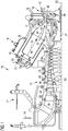
- FIG.2 shows the combustion apparatus 16 in sectional and schematic view.
- the burner plenum 26 is defined between a combustor casing 60 and a combustor chamber wall 62.
- the burner plenum 26 defines a volume of the combustion apparatus 16.
- a bleed arrangement comprises a conduit 102 that is connected to the combustor casing 60 and forms an inlet 104 such that fluid can pass between the plenum or volume 26 and the conduit 102.
- a Helmholtz resonator 100 is connected to the conduit 102 via an opening 108 such that fluid and acoustic pressure waves in the conduit 102 can pass into and out of the Helmholtz resonator 100.
- the bleed arrangement further comprises a valve 106 positioned between the conduit 102 and an exhaust ducting 107 to regulate fluid passing through the conduit 102 and through the exhaust ducting 107.
- the opening 108 of the Helmholtz resonator 100 is positioned on and in fluid communication with the conduit 102 and between the inlet 104 and the valve 106.
- the exhaust ducting 107 is connected to an inlet region of the compressor 14 and/or the inlet 12. Bleeding fluid from volume or plenum 26 through the conduit 102, the valve 106 and then the exhaust ducting 107 to either or even both the compressor 14 or inlet 12 can improve emissions of the gas turbine because flame stability is maintained and a more constant temperature of the flame is achieved.
- such bleeding can provide some energy recovery particularly in transient engine operating conditions or at part load output of the engine.
- bleeding to the engine's inlet can be advantageous in particularly cold ambient conditions to prevent icing and improve compressor efficiency.
- the bleed arrangement may comprise the exhaust duct 107 being connected to the engine's exhaust although no energy recovery is possible, this bleed does allow improved combustion stability and better emissions by virtue of a more constant flame temperature.
- a cooling air supply feed 110 is schematically shown connecting the compressor 14 to the Helmholtz resonator 100 such that pressurised cooling air from the compressor 14 can be supplied to the Helmholtz resonator 100.
- a cooler 112 and a valve arrangement 114 are located on the cooling air supply feed 110 and can cool the air being supplied to the Helmholtz resonator 100.
- the cooler 112 may incorporate the valve arrangement 114 as an integral part.
- the gas turbine engine further comprises an engine control unit (ECU) 120 and instrumentation such as a combustion dynamics probe 122 which is associated with the combustion apparatus 16 to measure any one or more of the combustor apparatus' parameters such as temperature of the combustion flame or surface temperature, pressure, pressure fluctuations, oscillations, harmonics or other dynamics or frequency.
- the engine control unit 120 is connected to the combustion dynamics probe 122 and the valve arrangement 114 to command the valve arrangement 114 to open and close dependent on the parameter being measured and/or used to determine a necessary change in the resonant frequency of the Helmholtz resonator 100, such as the temperature of the combustion apparatus 16. Cooling air is often supplied to instrumentation and this is particularly the case with the combustion dynamics probe 122 because it is located and extends through a base plate of the burner 30 and which is exposed to high combustion temperatures.
- the gas turbine engine 10 comprises an annular array of combustor apparatus 16, located evenly about the central axis 20.
- Each combustor apparatus 16 has at least one Helmholtz resonator 100 associated to it although more than one Helmholtz resonator 100 may be provided to each combustor apparatus 16.
- the at least one Helmholtz resonator 100 or the inlet 104 is located at the position of the pressure anti-node of the acoustic frequency to be attenuated.
- spent cooling air used to cool the combustion dynamics probe 122 can be routed by feed pipe 124 through the cooler 120 in addition to or instead of the cooling air supplied from the compressor 14. Furthermore, the spent cooling air is actually relatively hot and could be used to quickly heat the Helmholtz resonator 100 and the feed pipe 124' bypasses the cooler 120 and instead flows directly in to the valve arrangement 114.
- combustion dynamics probe 122' An alternative location of the combustion dynamics probe 122' is shown in dashed lines on Fig. 2 and where it is housed in or attached through the combustor casing 60. This radially inner part of the combustor casing 60 is known as the centre casing.
- the combustor casing 60 is significantly cooler than the burner 30 and within the temperature capability of the combustion dynamics probe 122' and does not require cooling.
- the engine control unit (ECU) 120 may receive information from one or all the combustion dynamics probes 122 and command the valve arrangement 114 to open and close dependent on the parameter being measured and/or used to determine a necessary change in the resonant frequency of the Helmholtz resonator 100.
- the information from more than one or all the combustion dynamics probes 122 may be averaged or even a lower/upper threshold has been reached for a specific parameter or parameters measured.
- each Helmholtz resonator 100 is connected to its own valve arrangement 114.
- Each valve arrangement 114 is connected to the compressor 114 either directly via a cooling air supply feed 110' or the cooling air supply feed 110 via the cooler 112.
- Each valve arrangement 114 is further connected to the feed pipe 124 and through the cooler 120 or the feed pipe 124' which bypasses the cooler 120.
- the ECU 120 connects to all the valve arrangements 114 and the combustion dynamics probes 122.
- cooling or heating of each Helmholtz resonator 100 may be independently achieved and therefore independently tuned to the acoustic resonant frequency of its combustion apparatus 16 or part of its annular combustor..
- the specific description above refers to two distinct ranges of acoustic frequencies to attenuate it is also possible that other ranges of acoustic frequencies may be attenuated by adjusting the temperature of the Helmholtz resonator's volume. Indeed, according the present invention, it is possible for the temperature of the volume (chamber 116) to be incrementally or variably adjusted anywhere between two opposing temperature extremes (i.e. maximum and minimum temperatures) to gradually vary the attenuation characteristic of the Helmholtz resonator of acoustic to attenuate a broad range of engine operating conditions between maximum output and engine start-up conditions.
Landscapes
- Engineering & Computer Science (AREA)
- Chemical & Material Sciences (AREA)
- Combustion & Propulsion (AREA)
- Mechanical Engineering (AREA)
- General Engineering & Computer Science (AREA)
- Soundproofing, Sound Blocking, And Sound Damping (AREA)
Description
- The present invention relates to a method of operating and an arrangement of a combustion apparatus of a gas turbine engine and particularly to a combustion apparatus having a Helmholtz resonator for the attenuation of combustion dynamics across a broad range of combustion dynamic frequencies. More particularly the Helmholtz resonator is a variable-frequency Helmholtz resonator.
- Dry Low Emission (DLE) combustion systems are known to be reliable in producing low NOx and having compact flames. However, most DLE combustion systems are prone to combustion dynamics, such as acoustic fluctuations, because they operate with a lean mixture of fuel and air in order to achieve low NOx emissions. Combustion dynamics can arise as a result of flame excitation, aerodynamic induced excitation or insufficient damping.
- Conventionally, acoustic damping of the critical frequency is performed. Known damping devices, such as Helmholtz resonators and perforated liners, are placed directly on the combustion chamber, inside/outside centre casings or on bleed pipes. The location of the damping devices on the combustion system is selected based on the maxima of the pressure anti-node of a specific acoustic frequency to be damped. Helmholtz resonators are known to be very effective at damping specific acoustic frequencies experienced by the combustion system. However, conventional Helmholtz resonators can only target a single operating condition of the engine or combustion system, e.g. a full load design point, where the acoustic resonance is at its worst or for the longest period of time.
- In these conventional damped combustion systems, when the demanded load is altered from 100% or maximum output to say 50-70% maximum output, the combustion system can be prone to a different acoustic frequency because the temperature, pressure and mass flow within the combustion system has changed. This different acoustic frequency can be problematic where the acoustic frequency of the combustor has shifted outside the range of the damping device's resonating frequency range. To overcome this problem a second set of Helmholtz resonators, tuned to the different acoustic frequency, can be implemented. However, this approach increases complexity, parts count, cost and can be compromised by geometric installation constraints.
- One alternative solution is present in
WO2011/128,156 which discloses a resonator device for damping a pressure oscillation within a combustion chamber, the resonator device comprising: a container filled with a gas; an opening in the container; and a heating element adapted to generate a flame. The flame is arranged to heat the gas within the container. The resonator device is comprised in a combustion arrangement, further comprising a combustion chamber for defining a combustion space for burning fuel. The container is connected to the combustion chamber such that an inside of the container is in communication with the combustion space via the opening. The resonator device has a resonance frequency equal to a pressure oscillation frequency within the combustion chamber under normal load conditions. -
EP1557 609 A1 discloses a Helmholtz resonator, which has a resonating volume in connection with the combustion chamber volume via a connective opening. The device has the unique characteristic that an adjustable flow of cooling air can be introduced into the resonating volume and connective opening. As opposed to other approaches for tuning a Helmholtz resonator, the present invention allows for the first time the resonance frequency of the Helmholtz resonator to be adjusted by a dynamic flow of cooling air. A method for damping thermoacoustic oscillations in a combustion chamber is also given, wherein a flow of cooling air is adjusted in order to modify the resonator characteristics of the Helmholtz resonator fluidically connected to the combustion chamber. - One objective of the present combustion apparatus is to attenuate more than one frequency range of combustion acoustics. Another objective is to identify and damp or attenuate combustor acoustic amplitude peaks at different engine operating loads. Another objective is to automatically control the attenuation frequency of the Helmholtz resonator to match shifts of the combustion dynamics peaks. Another objective is to minimise parts count. Another objective is to extend the engine's operating envelope for dry low-emission operation and especially at part-load. Another objective is to prevent resonance in a bleed arrangement of the combustor and prevent undesirable combustion dynamics. In this way natural frequencies of the bleed arrangement can be prevented from causing destructive combustion dynamics and prevent combustion flame instability.
- For these and other objectives and advantages there is provided a gas turbine engine comprising combustion apparatus defining a volume, a compressor, a cooling air supply feed from the compressor, a bleed arrangement comprising a conduit, the conduit is connected to the volume such that fluid can be bled from the volume through the conduit, a Helmholtz resonator. The Helmholtz resonator comprises a neck and a chamber having an attenuation volume and which is in fluid communication with the volume. The Helmholtz resonator is connected to the conduit such that fluid in the conduit can pass therebetween. The cooling air supply feed is connected to the Helmholtz resonator and comprises a valve arrangement. The valve arrangement is configured such that in a first engine operating condition the valve arrangement is closed and the Helmholtz resonator attenuates acoustic frequencies in a first range and in a second engine operating condition the valve arrangement is open whereby cooling air purges the attenuation volume and the Helmholtz resonator attenuates acoustic frequencies in a second range. The gas turbine engine further comprises a combustion dynamics probe configured to measure a temperature in the combustion apparatus and an engine control unit. The engine control unit is connected to the combustion dynamics probe and to the valve arrangement and is configured to command the valve arrangement to open and close depending on the temperature being measured by the combustion dynamics probe.
- The first engine operating condition may be at a different load output than the second engine operating condition. Preferably the first engine operating condition is at a higher output than the second engine operating condition.
- During the first engine operating condition the Helmholtz resonator may be at a higher temperature than at the second engine operating condition.
- The gas turbine engine further comprises an engine control unit and a combustion dynamics probe associated with the combustion apparatus. The engine control unit is connected to the combustion dynamics probe and the valve arrangement to command the valve arrangement to open and close dependent on the acoustic frequency of the combustion apparatus.
- The gas turbine engine further comprises an annular combustor apparatus. Alternatively, the gas turbine engine further comprises an annular array of combustor apparatus each having at least one Helmholtz resonator.
- Each Helmholtz resonator may be connected to its own valve arrangement and opened or closed independently of the other valve arrangements.
- Each Helmholtz resonator may be connected to a single valve arrangement.
- The cooling air supply feed may comprise a cooler to cool the air supplied to the Helmholtz resonator(s).
- In the first range the acoustic frequencies may be between 120Hz and 160Hz, preferably between 132Hz and 142Hz and more preferably at approximately 137Hz. In the second range the acoustic frequencies may be between 75Hz and 115Hz, preferably between 90Hz and 100Hz and more preferably at approximately 95Hz.
- In the first engine operating condition the temperature may be between 590K and 790K, preferably 640K and 730K or more preferably approximately 690K. In the second engine operating condition the temperature may be between 300K and 400K, preferably 325K and 375K and more preferably 350K.
- In the first engine operating condition the engine may be operating at at least 90% of its maximum output. In the second engine operating condition the engine may be operating between 50% and 75% of its maximum output.
- The geometry of the neck and the chamber of the Helmholtz resonator may be set to attenuate acoustic frequencies in a first range.
- The bleed arrangement may further comprises a valve and an exhaust ducting, the valve is situated between the conduit and the exhaust ducting.
- The exhaust ducting may be connected to any one or more of an inlet of the compressor, an inlet of the gas turbine engine, an exhaust duct of the gas turbine engine.
- In another aspect of the present invention there is provided a method of operating a gas turbine engine according to any one of the above paragraphs. The method comprising the steps of detecting a change in temperature in the combustion apparatus whereby the acoustic frequency to be attenuated at the first engine operating condition is outside the range of the Helmholtz resonator and opening the valve arrangement and supplying cooling air the Helmholtz resonator such that it attenuates acoustic frequencies in the second range.
- The method may comprise the steps of detecting a change in temperature in the combustion apparatus whereby the acoustic frequency to be attenuated at the second engine operating condition is outside the range of the Helmholtz resonator being supplied with cooling air and closing the valve arrangement to reduce or stop the supply of cooling air to the Helmholtz resonator such that it attenuates acoustic frequencies in the first range.
- The method may comprise the step of bleeding a fluid from the volume. Controlling bleeding the fluid from the combustor may be achieved by operation of the valve between an open and a closed position.
- The above mentioned attributes and other features and advantages of this invention and the manner of attaining them will become more apparent and the invention itself will be better understood by reference to the following description of embodiments of the invention taken in conjunction with the accompanying drawings, wherein
-
FIG. 1 shows part of a turbine engine in a sectional view and in which a combustion apparatus having a variable frequency attenuating Helmholtz resonator may be incorporated, -
FIG. 2 shows a schematic outline of the combustion apparatus having further equipment associated to enable the variable frequency attenuating Helmholtz resonator, -
FIG. 3 is a schematic illustration of a transverse section through the gas turbine engine and showing aspects of an embodiment of the combustion apparatus and the Helmholtz resonator arrangement, -
FIG. 4 is a schematic illustration of a transverse section through the gas turbine engine and showing aspects of another embodiment of the combustion apparatus and the Helmholtz resonator arrangement. -
FIG. 1 shows an example of agas turbine engine 10 in a sectional view. Thegas turbine engine 10 comprises, in flow series, aninlet 12, a compressor orcompressor section 14, acombustor section 16,aturbine section 18 and an exhaust duct (not shown) which are generally arranged in flow series and generally about and in the direction of a longitudinal orrotational axis 20. Thegas turbine engine 10 further comprises ashaft 22 which is rotatable about therotational axis 20 and which extends longitudinally through thegas turbine engine 10. Theshaft 22 drivingly connects theturbine section 18 to thecompressor section 14. - In operation of the
gas turbine engine 10,air 24, which is taken in through theair inlet 12 is compressed by thecompressor section 14 and delivered to the combustion section orburner section 16. Theburner section 16 comprises alongitudinal axis 35 of the burner, aburner plenum 26, one ormore combustion chambers 28 and at least oneburner 30 fixed to eachcombustion chamber 28. Thecombustion chambers 28 and theburners 30 are located inside theburner plenum 26. The compressed air passing through thecompressor 14 enters adiffuser 32 and is discharged from thediffuser 32 into theburner plenum 26 from where a portion of the air enters theburner 30 and is mixed with a gaseous or liquid fuel. The air/fuel mixture is then burned and thecombustion gas 34 or working gas from the combustion is channelled through thecombustion chamber 28 to theturbine section 18 via atransition duct 17. - This exemplary
gas turbine engine 10 has a cannularcombustor section arrangement 16, which is constituted by an annular array ofcombustor cans 19 each having theburner 30 and thecombustion chamber 28, thetransition duct 17 has a generally circular inlet that interfaces with thecombustor chamber 28 and an outlet in the form of an annular segment. The cannularcombustor section arrangement 16 is more generally referred to ascombustion apparatus 16 and which is intended to comprise other combustor arrangements such as an annular combustor. An annular array of transition duct outlets form an annulus for channelling the combustion gases to theturbine 18. - The
turbine section 18 comprises a number ofblade carrying discs 36 attached to theshaft 22. In the present example, twodiscs 36 each carry an annular array ofturbine blades 38. However, the number of blade carrying discs could be different, i.e. only one disc or more than two discs. In addition, guidingvanes 40, which are fixed to astator 42 of thegas turbine engine 10, are disposed between the stages of annular arrays ofturbine blades 38. Between the exit of thecombustion chamber 28 and the leadingturbine blades 38inlet guiding vanes 44 are provided and turn the flow of working gas onto theturbine blades 38. - The combustion gas from the
combustion chamber 28 enters theturbine section 18 and drives theturbine blades 38 which in turn rotate theshaft 22. The guidingvanes turbine blades 38. - The
turbine section 18 drives thecompressor section 14. Thecompressor section 14 comprises an axial series of vane stages 46 and rotor blade stages 48. The rotor blade stages 48 comprise a rotor disc supporting an annular array of blades. Thecompressor section 14 also comprises acasing 50 that surrounds the rotor stages and supports the vane stages 48. The guide vane stages include an annular array of radially extending vanes that are mounted to thecasing 50. The vanes are provided to present gas flow at an optimal angle for the blades at a given engine operational point. Some of the guide vane stages have variable vanes, where the angle of the vanes, about their own longitudinal axis, can be adjusted for angle according to air flow characteristics that can occur at different engine operation conditions. - The
casing 50 defines a radiallyouter surface 52 of thepassage 56 of thecompressor 14. A radiallyinner surface 54 of thepassage 56 is at least partly defined by arotor drum 53 of the rotor which is partly defined by the annular array ofblades 48. - The present technique is described with reference to the above exemplary turbine engine having a single shaft or spool connecting a single, multi-stage compressor and a single, one or more stage turbine. However, it should be appreciated that the present technique is equally applicable to two or three shaft engines and which can be used for industrial, aero or marine applications.
- The terms upstream and downstream refer to the flow direction of the airflow and/or working gas flow through the engine unless otherwise stated. The terms forward and rearward refer to the general flow of gas through the engine. The terms axial, radial and circumferential are made with reference to the
rotational axis 20 of the engine. -
FIG.2 shows thecombustion apparatus 16 in sectional and schematic view. Theburner plenum 26 is defined between acombustor casing 60 and acombustor chamber wall 62. Theburner plenum 26 defines a volume of thecombustion apparatus 16. A bleed arrangement comprises aconduit 102 that is connected to thecombustor casing 60 and forms aninlet 104 such that fluid can pass between the plenum orvolume 26 and theconduit 102. AHelmholtz resonator 100 is connected to theconduit 102 via anopening 108 such that fluid and acoustic pressure waves in theconduit 102 can pass into and out of theHelmholtz resonator 100. The bleed arrangement further comprises avalve 106 positioned between theconduit 102 and anexhaust ducting 107 to regulate fluid passing through theconduit 102 and through theexhaust ducting 107. Theopening 108 of theHelmholtz resonator 100 is positioned on and in fluid communication with theconduit 102 and between theinlet 104 and thevalve 106. - The
exhaust ducting 107 is connected to an inlet region of thecompressor 14 and/or theinlet 12. Bleeding fluid from volume orplenum 26 through theconduit 102, thevalve 106 and then theexhaust ducting 107 to either or even both thecompressor 14 orinlet 12 can improve emissions of the gas turbine because flame stability is maintained and a more constant temperature of the flame is achieved. Advantageously, such bleeding can provide some energy recovery particularly in transient engine operating conditions or at part load output of the engine. Further, bleeding to the engine's inlet can be advantageous in particularly cold ambient conditions to prevent icing and improve compressor efficiency. In addition or alternatively, the bleed arrangement may comprise theexhaust duct 107 being connected to the engine's exhaust although no energy recovery is possible, this bleed does allow improved combustion stability and better emissions by virtue of a more constant flame temperature. - With the
Helmholtz resonator 100 attached to theconduit 102 pressure waves in thecombustor volume 26 and that pass into theconduit 102 may be damped successfully to prevent resonance in theconduit 102 and undesirable combustion dynamics. In this way natural frequencies of the bleed arrangement can be prevented from causing destructive combustion dynamics and prevent combustion flame instability. - A cooling
air supply feed 110 is schematically shown connecting thecompressor 14 to theHelmholtz resonator 100 such that pressurised cooling air from thecompressor 14 can be supplied to theHelmholtz resonator 100. A cooler 112 and avalve arrangement 114 are located on the coolingair supply feed 110 and can cool the air being supplied to theHelmholtz resonator 100. The cooler 112 may incorporate thevalve arrangement 114 as an integral part. - The gas turbine engine further comprises an engine control unit (ECU) 120 and instrumentation such as a
combustion dynamics probe 122 which is associated with thecombustion apparatus 16 to measure any one or more of the combustor apparatus' parameters such as temperature of the combustion flame or surface temperature, pressure, pressure fluctuations, oscillations, harmonics or other dynamics or frequency. Theengine control unit 120 is connected to thecombustion dynamics probe 122 and thevalve arrangement 114 to command thevalve arrangement 114 to open and close dependent on the parameter being measured and/or used to determine a necessary change in the resonant frequency of theHelmholtz resonator 100, such as the temperature of thecombustion apparatus 16. Cooling air is often supplied to instrumentation and this is particularly the case with thecombustion dynamics probe 122 because it is located and extends through a base plate of theburner 30 and which is exposed to high combustion temperatures. - In this exemplary embodiment, the
gas turbine engine 10 comprises an annular array ofcombustor apparatus 16, located evenly about thecentral axis 20. Eachcombustor apparatus 16 has at least oneHelmholtz resonator 100 associated to it although more than oneHelmholtz resonator 100 may be provided to eachcombustor apparatus 16. The at least oneHelmholtz resonator 100 or theinlet 104 is located at the position of the pressure anti-node of the acoustic frequency to be attenuated. - In a further embodiment, spent cooling air used to cool the
combustion dynamics probe 122 can be routed byfeed pipe 124 through the cooler 120 in addition to or instead of the cooling air supplied from thecompressor 14. Furthermore, the spent cooling air is actually relatively hot and could be used to quickly heat theHelmholtz resonator 100 and the feed pipe 124' bypasses the cooler 120 and instead flows directly in to thevalve arrangement 114. - An alternative location of the combustion dynamics probe 122' is shown in dashed lines on
Fig. 2 and where it is housed in or attached through thecombustor casing 60. This radially inner part of thecombustor casing 60 is known as the centre casing. Thecombustor casing 60 is significantly cooler than theburner 30 and within the temperature capability of the combustion dynamics probe 122' and does not require cooling. - Other gas turbine engines may comprise an annular combustor apparatus and an array of
Helmholtz resonators 100 may be located around the circumference of the combustor apparatus. - In both examples of a gas turbine engine each
Helmholtz resonator 100 is connected to asingle valve arrangement 114 such that eachHelmholtz resonator 100 receives cooling air at the same time and the same quantity of cooling air. This is schematically shown inFIG. 3 where adelivery pipe 111 is connected between thevalve arrangement 114 and at least oneHelmholtz resonator 100 on each combustor 16 or spaced around an annular combustor in other examples. Thefeed pipe 111 surrounds at least a part of the gas turbine engine and supplies cooling air to theindividual Helmholtz resonators 100. The engine control unit (ECU) 120 may receive information from one or all the combustion dynamics probes 122 and command thevalve arrangement 114 to open and close dependent on the parameter being measured and/or used to determine a necessary change in the resonant frequency of theHelmholtz resonator 100. The information from more than one or all the combustion dynamics probes 122 may be averaged or even a lower/upper threshold has been reached for a specific parameter or parameters measured. - Alternatively, as shown in
Fig. 4 eachHelmholtz resonator 100 is connected to itsown valve arrangement 114. Eachvalve arrangement 114, as before, is connected to thecompressor 114 either directly via a cooling air supply feed 110' or the coolingair supply feed 110 via thecooler 112. Eachvalve arrangement 114 is further connected to thefeed pipe 124 and through the cooler 120 or the feed pipe 124' which bypasses the cooler 120. Although not shown, theECU 120 connects to all thevalve arrangements 114 and the combustion dynamics probes 122. Thus cooling or heating of eachHelmholtz resonator 100 may be independently achieved and therefore independently tuned to the acoustic resonant frequency of itscombustion apparatus 16 or part of its annular combustor.. - The Helmholtz resonator(s) 100 is generally conventional in its construction and comprises a neck 118 leading from the
inlet 115 to achamber 116. Thechamber 116 defines anattenuation volume 116 which is in fluid communication with the plenum'svolume 26. However, thepresent Helmholtz resonator 100 comprises an aperture 121 to which the coolingair supply feed 110 is connected. - As is known in the art, the geometry of the
Helmholtz resonator device 100 governs the resonance frequency f of the resonator device according to the following formula:
- S - the cross sectional area of the neck of the resonator
- V - resonator's volume
- I' - the effective length of resonator's neck, which is based on the geometric neck length L2
- c - the speed of sound
- In its broadest sense the present arrangement is such that in a first engine operating condition the
valve arrangement 114 is closed and theHelmholtz resonator 100 is designed and has its geometry set to attenuate acoustic frequencies in a first range and in a second engine operating condition thevalve arrangement 114 is open whereby cooling air purges the attenuation volume and theHelmholtz resonator 100 attenuates acoustic frequencies in a second range. This change of attenuation frequencies is realised by virtue of a change in temperature of the air in theHelmholtz resonator 100. During the first engine operating condition theHelmholtz resonator 100 is at a higher temperature than at the second engine operating condition. Normally the first engine operating condition is at a higher load output than the second engine operating condition although in certain transitional engine operating conditions this might not occur. - The Helmholtz resonator's 100 geometry is set by the combustor' acoustic frequency to be attenuated in the first range and where the engine is either operating for the longest duration or where the most deleterious acoustic frequency occurs. Generally, the acoustic frequency to be attenuated is between 120Hz and 160Hz and in one embodiment is between 132Hz and 142Hz with the most prevalent frequency being approximately 137Hz. The acoustic frequency in the second engine operating condition is generally between 75Hz and 115Hz and in one embodiment is between 90Hz and 100Hz with the most prevalent frequency being approximately 95Hz. For the
present Helmholtz resonator 100 the first and second acoustic frequency ranges do not overlap. It is possible for the first and second acoustic frequency ranges to overlap, although preferably the mid-point of each range is outside the range of the other range. - Normally during the first engine operating condition the air temperature from the compressor exit is between 590K and 790K and often in the range 640K and 730K in a specific example is approximately 690K and in the second engine operating condition the temperature is between 300K and 400K, preferably 325K and 375K and more preferably 350K.
- Furthermore, in the first engine operating condition the engine is operating at at least 90% of its maximum output and which can be 100%. In the second engine operating condition the engine is operating between 50% and 75% of its maximum output.
- The
ECU 120 which receives signals from thecombustion dynamics probe 122 on the operating condition (measured parameters) of thecombustion apparatus 16 and calculates via an algorithm the required temperature of theHelmholtz resonator 100 and open the valve arrangement to introduce cooling air to theHelmholtz resonator 100 in order to attenuate a second or different acoustic frequency of the combustor. The algorithm may include a signal indicative of a change in the demanded output of the engine and via a known calibration of behaviours of the combustion apparatus dependent on the demanded output and command thevalve arrangement 114 to open or close, partly or wholly, such that the temperature of theHelmholtz resonator 100 is adjusted gradually and quickly. In this way the Helmholtz resonator's 100 attenuation frequency can be variably adjusted during transitions between the first and second engine operating conditions. - Thus a method of operating a gas turbine engine comprising the steps of detecting a change in temperature in the combustion apparatus whereby the acoustic frequency to be attenuated at the first engine operating condition is outside the range of the Hz resonator and opening the
valve arrangement 114 and supplying cooling air the Hz resonator such that it attenuates acoustic frequencies in the second range. - Although the specific description above refers to two distinct ranges of acoustic frequencies to attenuate it is also possible that other ranges of acoustic frequencies may be attenuated by adjusting the temperature of the Helmholtz resonator's volume. Indeed, according the present invention, it is possible for the temperature of the volume (chamber 116) to be incrementally or variably adjusted anywhere between two opposing temperature extremes (i.e. maximum and minimum temperatures) to gradually vary the attenuation characteristic of the Helmholtz resonator of acoustic to attenuate a broad range of engine operating conditions between maximum output and engine start-up conditions.
Claims (15)
- A gas turbine engine comprisinga combustion apparatus (16) defining a volume (26),a compressor (14),a cooling air supply feed (110) from the compressor (14),a bleed arrangement comprising a conduit (102), the conduit (102) is connected to the volume (26) such that fluid can be bled from the volume (26) through the conduit (102),a Helmholtz resonator (100), the Helmholtz resonator (100) comprises a neck (118) and a chamber (116) having an attenuation volume (116) and which is in fluid communication with the volume (26),the Helmholtz resonator (100) is connected to the conduit (102) such that fluid in the conduit (102) can pass therebetween,the cooling air supply feed (110) is connected to the Helmholtz resonator (100) and comprises a valve arrangement (114),wherein the valve arrangement (114) is configured such that in a first engine operating condition the valve arrangement (114) is closed and the Helmholtz resonator (100) attenuates acoustic frequencies in a first range and in a second engine operating condition the valve arrangement (114) is open whereby cooling air purges the attenuation volume (116) and the Helmholtz resonator (100) attenuates acoustic frequencies in a second range,wherein the gas turbine engine further comprisesa combustion dynamics probe (122, 122') configured to measure a temperature inthe combustion apparatus (16),an engine control unit (120),the engine control unit (120) is connected to the combustion dynamics probe (122, 122') and to the valve arrangement (114) and is configured to command the valve arrangement (114) to open and close depending on the temperature being measured by the combustion dynamics probe (122, 122').
- A gas turbine engine as claimed in claim 1 whereinthe first engine operating condition is at a different load output than the second engine operating condition, preferably the first engine operating condition is at a higher output than the second engine operating condition, and/orduring the first engine operating condition the Helmholtz resonator (100) is at a higher temperature than at the second engine operating condition.
- A gas turbine engine as claimed in any one of claims 1-2 whereinthe gas turbine engine further comprisesan engine control unit anda combustion dynamics probe (122) associated with the combustion apparatus,the engine control unit is connected to the combustion dynamics probe (122, 122') and the valve arrangement (114) to command the valve arrangement (114) to open and close dependent on the acoustic frequency of the combustion apparatus.
- A gas turbine engine as claimed in any one of claims 1-3 wherein
the gas turbine engine further comprisesan annular combustor apparatus oran annular array of combustor apparatus (16) each having at least one Helmholtz resonator (100). - A gas turbine engine as claimed in claim 4 whereineach Helmholtz resonator (100) is connected to its own valve arrangement (114) and opened or closed independently of the other valve arrangements (114) oreach Helmholtz resonator (100) is connected to a single valve arrangement (114).
- A gas turbine engine as claimed in any one of claims 1-5 wherein
the cooling air supply feed comprises a cooler to cool the air supplied to the Helmholtz resonator(s) (100). - A gas turbine engine as claimed in any one of claims 1-6 whereinin the first range the acoustic frequencies is between 120Hz and 160Hz, preferably between 132Hz and 142Hz and more preferably at approximately 137Hz andin the second range the acoustic frequencies is between 75Hz and 115Hz, preferably between 90Hz and 100Hz and more preferably at approximately 95Hz.
- A gas turbine engine as claimed in any one of claims 1-7 whereinin the first engine operating condition the temperature is between 590K and 790K, preferably 640K and 730K or more preferably approximately 690K andand in the second engine operating condition the temperature is between 300K and 400K, preferably 325K and 375K and more preferably 350K.
- A gas turbine engine as claimed in any one of claims 1-8 whereinin the first engine operating condition the engine is operating at at least 90% of its maximum output,and in the second engine operating condition the engine is operating between 50% and 75% of its maximum output.
- A gas turbine engine as claimed in any one of claims 1-9 wherein the geometry of the neck (118) and the chamber (116) of the Helmholtz resonator (100) is set to attenuate acoustic frequencies in a first range.
- A gas turbine engine as claimed in any one of claims 1-10 wherein the bleed arrangement further comprises a valve (106) and an exhaust ducting (107), the valve (106) is situated between the conduit (102) and the exhaust ducting (107).
- A gas turbine engine as claimed in claim 11 wherein the exhaust ducting (107) is connected to any one or more of an inlet of the compressor (14), an inlet (12) of the gas turbine engine, an exhaust duct of the gas turbine engine.
- A method of operating a gas turbine engine according to any one of claims 1-12, the method characterised by the steps ofdetecting a change in temperature in the combustion apparatus whereby the acoustic frequency to be attenuated at the first engine operating condition is outside the range of the Helmholtz resonator (100) andopening the valve arrangement (114) and supplying cooling air the Helmholtz resonator (100) such that it attenuates acoustic frequencies in the second range.
- A method of operating a gas turbine engine according to claim 13, the method comprising the steps ofdetecting a change in temperature in the combustion apparatus whereby the acoustic frequency to be attenuated at the second engine operating condition is outside the range of the Helmholtz resonator (100) being supplied with cooling air andclosing the valve arrangement (114) to reduce or stop the supply of cooling air to the Helmholtz resonator (100) such that it attenuates acoustic frequencies in the first range.
- A method of operating a gas turbine engine according to any one of claims 13-14, the method comprising the steps of
bleeding a fluid from the volume (26).
Applications Claiming Priority (2)
| Application Number | Priority Date | Filing Date | Title |
|---|---|---|---|
| EP17182951.8A EP3434876A1 (en) | 2017-07-25 | 2017-07-25 | Combustor apparatus and method of operating combustor apparatus |
| PCT/EP2018/069565 WO2019020474A1 (en) | 2017-07-25 | 2018-07-18 | Combustor apparatus and method of operating combustor apparatus |
Publications (2)
| Publication Number | Publication Date |
|---|---|
| EP3658759A1 EP3658759A1 (en) | 2020-06-03 |
| EP3658759B1 true EP3658759B1 (en) | 2021-04-28 |
Family
ID=59416540
Family Applications (2)
| Application Number | Title | Priority Date | Filing Date |
|---|---|---|---|
| EP17182951.8A Withdrawn EP3434876A1 (en) | 2017-07-25 | 2017-07-25 | Combustor apparatus and method of operating combustor apparatus |
| EP18746645.3A Active EP3658759B1 (en) | 2017-07-25 | 2018-07-18 | Combustor apparatus and method of operating combustor apparatus |
Family Applications Before (1)
| Application Number | Title | Priority Date | Filing Date |
|---|---|---|---|
| EP17182951.8A Withdrawn EP3434876A1 (en) | 2017-07-25 | 2017-07-25 | Combustor apparatus and method of operating combustor apparatus |
Country Status (4)
| Country | Link |
|---|---|
| US (1) | US11525396B2 (en) |
| EP (2) | EP3434876A1 (en) |
| ES (1) | ES2880301T3 (en) |
| WO (1) | WO2019020474A1 (en) |
Families Citing this family (1)
| Publication number | Priority date | Publication date | Assignee | Title |
|---|---|---|---|---|
| US20250341310A1 (en) * | 2024-05-02 | 2025-11-06 | General Electric Company | Turbine engine combustor having a tunable acoustic damper |
Family Cites Families (16)
| Publication number | Priority date | Publication date | Assignee | Title |
|---|---|---|---|---|
| DE4414232A1 (en) * | 1994-04-23 | 1995-10-26 | Abb Management Ag | Device for damping thermoacoustic vibrations in a combustion chamber |
| US6089025A (en) * | 1998-08-24 | 2000-07-18 | General Electric Company | Combustor baffle |
| DE10026121A1 (en) * | 2000-05-26 | 2001-11-29 | Alstom Power Nv | Device for damping acoustic vibrations in a combustion chamber |
| DE10231238B4 (en) * | 2002-07-11 | 2004-06-03 | J. Eberspächer GmbH & Co. KG | Noise damping device |
| JP4177727B2 (en) * | 2003-07-31 | 2008-11-05 | 東京電力株式会社 | Gas turbine combustor |
| EP1557609B1 (en) * | 2004-01-21 | 2016-03-16 | Siemens Aktiengesellschaft | Device and method for damping thermoacoustic oscillations in a combustion chamber |
| US8408004B2 (en) * | 2009-06-16 | 2013-04-02 | General Electric Company | Resonator assembly for mitigating dynamics in gas turbines |
| EP2302302A1 (en) * | 2009-09-23 | 2011-03-30 | Siemens Aktiengesellschaft | Helmholtz resonator for a gas turbine combustion chamber |
| EP2378199A1 (en) * | 2010-04-13 | 2011-10-19 | Siemens Aktiengesellschaft | Resonator device for damping the pressure oscillation within a combustion chamber and a method for operating a combustion arrangement |
| DE102010015065B4 (en) | 2010-04-15 | 2012-04-12 | Siemens Aktiengesellschaft | Device for positioning patients |
| US20120204534A1 (en) * | 2011-02-15 | 2012-08-16 | General Electric Company | System and method for damping pressure oscillations within a pulse detonation engine |
| EP2559945A1 (en) * | 2011-08-17 | 2013-02-20 | Siemens Aktiengesellschaft | Combustion arrangement and turbine comprising a damping facility |
| JP5908379B2 (en) * | 2012-09-24 | 2016-04-26 | 三菱日立パワーシステムズ株式会社 | Gas turbine combustor |
| US20150082794A1 (en) * | 2013-09-26 | 2015-03-26 | Reinhard Schilp | Apparatus for acoustic damping and operational control of damping, cooling, and emissions in a gas turbine engine |
| US10513984B2 (en) * | 2015-08-25 | 2019-12-24 | General Electric Company | System for suppressing acoustic noise within a gas turbine combustor |
| EP3182008A1 (en) * | 2015-12-18 | 2017-06-21 | Ansaldo Energia IP UK Limited | Helmholtz damper for a gas turbine and gas turbine with such helmholtz damper |
-
2017
- 2017-07-25 EP EP17182951.8A patent/EP3434876A1/en not_active Withdrawn
-
2018
- 2018-07-18 WO PCT/EP2018/069565 patent/WO2019020474A1/en not_active Ceased
- 2018-07-18 ES ES18746645T patent/ES2880301T3/en active Active
- 2018-07-18 US US16/631,224 patent/US11525396B2/en active Active
- 2018-07-18 EP EP18746645.3A patent/EP3658759B1/en active Active
Also Published As
| Publication number | Publication date |
|---|---|
| ES2880301T3 (en) | 2021-11-24 |
| US11525396B2 (en) | 2022-12-13 |
| US20200141577A1 (en) | 2020-05-07 |
| EP3434876A1 (en) | 2019-01-30 |
| EP3658759A1 (en) | 2020-06-03 |
| WO2019020474A1 (en) | 2019-01-31 |
Similar Documents
| Publication | Publication Date | Title |
|---|---|---|
| JP4429730B2 (en) | gas turbine | |
| EP3610145B1 (en) | Gas turbine engine fuel manifold damper and method of dynamics attenuation | |
| JP2011052954A (en) | Acoustically stiffened gas turbine combustor supply | |
| JP2014163664A (en) | Fuel nozzle for reducing modal coupling of combustion dynamics | |
| JP2012117807A (en) | Wide frequency response tunable resonator | |
| CN105008805A (en) | Damping device for a gas turbine, gas turbine and method for damping thermo-acoustic vibrations | |
| EP3452756B1 (en) | High frequency acoustic damper for combustor liners and method of damping | |
| WO2014173660A1 (en) | Combustion system of a flow engine and method for determining a dimension of a resonator cavity | |
| CN101818899A (en) | System and method for reducing combustion dynamics in a turbine | |
| US9644845B2 (en) | System and method for reducing modal coupling of combustion dynamics | |
| US20080118343A1 (en) | Combustion control for a gas turbine | |
| EP3658759B1 (en) | Combustor apparatus and method of operating combustor apparatus | |
| EP2745054B1 (en) | Combustion arrangement and turbine comprising a damping facility | |
| CN108869041A (en) | Front end for gas turbines turns to spoon shape part | |
| US10180108B2 (en) | System and method for operating a gas turbine | |
| US11274610B2 (en) | Combustion system control | |
| US9689317B2 (en) | System and method for operating a gas turbine | |
| CN120968880A (en) | Turbine engine with damper |
Legal Events
| Date | Code | Title | Description |
|---|---|---|---|
| STAA | Information on the status of an ep patent application or granted ep patent |
Free format text: STATUS: UNKNOWN |
|
| STAA | Information on the status of an ep patent application or granted ep patent |
Free format text: STATUS: THE INTERNATIONAL PUBLICATION HAS BEEN MADE |
|
| PUAI | Public reference made under article 153(3) epc to a published international application that has entered the european phase |
Free format text: ORIGINAL CODE: 0009012 |
|
| STAA | Information on the status of an ep patent application or granted ep patent |
Free format text: STATUS: REQUEST FOR EXAMINATION WAS MADE |
|
| 17P | Request for examination filed |
Effective date: 20191220 |
|
| AK | Designated contracting states |
Kind code of ref document: A1 Designated state(s): AL AT BE BG CH CY CZ DE DK EE ES FI FR GB GR HR HU IE IS IT LI LT LU LV MC MK MT NL NO PL PT RO RS SE SI SK SM TR |
|
| AX | Request for extension of the european patent |
Extension state: BA ME |
|
| DAV | Request for validation of the european patent (deleted) | ||
| DAX | Request for extension of the european patent (deleted) | ||
| GRAP | Despatch of communication of intention to grant a patent |
Free format text: ORIGINAL CODE: EPIDOSNIGR1 |
|
| STAA | Information on the status of an ep patent application or granted ep patent |
Free format text: STATUS: GRANT OF PATENT IS INTENDED |
|
| INTG | Intention to grant announced |
Effective date: 20201217 |
|
| RAP1 | Party data changed (applicant data changed or rights of an application transferred) |
Owner name: SIEMENS ENERGY GLOBAL GMBH & CO. KG |
|
| GRAS | Grant fee paid |
Free format text: ORIGINAL CODE: EPIDOSNIGR3 |
|
| GRAA | (expected) grant |
Free format text: ORIGINAL CODE: 0009210 |
|
| STAA | Information on the status of an ep patent application or granted ep patent |
Free format text: STATUS: THE PATENT HAS BEEN GRANTED |
|
| AK | Designated contracting states |
Kind code of ref document: B1 Designated state(s): AL AT BE BG CH CY CZ DE DK EE ES FI FR GB GR HR HU IE IS IT LI LT LU LV MC MK MT NL NO PL PT RO RS SE SI SK SM TR |
|
| REG | Reference to a national code |
Ref country code: GB Ref legal event code: FG4D |
|
| RIN1 | Information on inventor provided before grant (corrected) |
Inventor name: BULAT, GHENADIE |
|
| REG | Reference to a national code |
Ref country code: CH Ref legal event code: EP |
|
| REG | Reference to a national code |
Ref country code: AT Ref legal event code: REF Ref document number: 1387302 Country of ref document: AT Kind code of ref document: T Effective date: 20210515 |
|
| REG | Reference to a national code |
Ref country code: DE Ref legal event code: R096 Ref document number: 602018016301 Country of ref document: DE |
|
| REG | Reference to a national code |
Ref country code: IE Ref legal event code: FG4D |
|
| REG | Reference to a national code |
Ref country code: LT Ref legal event code: MG9D |
|
| REG | Reference to a national code |
Ref country code: AT Ref legal event code: MK05 Ref document number: 1387302 Country of ref document: AT Kind code of ref document: T Effective date: 20210428 |
|
| PG25 | Lapsed in a contracting state [announced via postgrant information from national office to epo] |
Ref country code: LT Free format text: LAPSE BECAUSE OF FAILURE TO SUBMIT A TRANSLATION OF THE DESCRIPTION OR TO PAY THE FEE WITHIN THE PRESCRIBED TIME-LIMIT Effective date: 20210428 Ref country code: HR Free format text: LAPSE BECAUSE OF FAILURE TO SUBMIT A TRANSLATION OF THE DESCRIPTION OR TO PAY THE FEE WITHIN THE PRESCRIBED TIME-LIMIT Effective date: 20210428 Ref country code: FI Free format text: LAPSE BECAUSE OF FAILURE TO SUBMIT A TRANSLATION OF THE DESCRIPTION OR TO PAY THE FEE WITHIN THE PRESCRIBED TIME-LIMIT Effective date: 20210428 Ref country code: NL Free format text: LAPSE BECAUSE OF FAILURE TO SUBMIT A TRANSLATION OF THE DESCRIPTION OR TO PAY THE FEE WITHIN THE PRESCRIBED TIME-LIMIT Effective date: 20210428 Ref country code: BG Free format text: LAPSE BECAUSE OF FAILURE TO SUBMIT A TRANSLATION OF THE DESCRIPTION OR TO PAY THE FEE WITHIN THE PRESCRIBED TIME-LIMIT Effective date: 20210728 Ref country code: AT Free format text: LAPSE BECAUSE OF FAILURE TO SUBMIT A TRANSLATION OF THE DESCRIPTION OR TO PAY THE FEE WITHIN THE PRESCRIBED TIME-LIMIT Effective date: 20210428 |
|
| REG | Reference to a national code |
Ref country code: ES Ref legal event code: FG2A Ref document number: 2880301 Country of ref document: ES Kind code of ref document: T3 Effective date: 20211124 |
|
| PG25 | Lapsed in a contracting state [announced via postgrant information from national office to epo] |
Ref country code: NO Free format text: LAPSE BECAUSE OF FAILURE TO SUBMIT A TRANSLATION OF THE DESCRIPTION OR TO PAY THE FEE WITHIN THE PRESCRIBED TIME-LIMIT Effective date: 20210728 Ref country code: LV Free format text: LAPSE BECAUSE OF FAILURE TO SUBMIT A TRANSLATION OF THE DESCRIPTION OR TO PAY THE FEE WITHIN THE PRESCRIBED TIME-LIMIT Effective date: 20210428 Ref country code: PL Free format text: LAPSE BECAUSE OF FAILURE TO SUBMIT A TRANSLATION OF THE DESCRIPTION OR TO PAY THE FEE WITHIN THE PRESCRIBED TIME-LIMIT Effective date: 20210428 Ref country code: PT Free format text: LAPSE BECAUSE OF FAILURE TO SUBMIT A TRANSLATION OF THE DESCRIPTION OR TO PAY THE FEE WITHIN THE PRESCRIBED TIME-LIMIT Effective date: 20210830 Ref country code: RS Free format text: LAPSE BECAUSE OF FAILURE TO SUBMIT A TRANSLATION OF THE DESCRIPTION OR TO PAY THE FEE WITHIN THE PRESCRIBED TIME-LIMIT Effective date: 20210428 Ref country code: SE Free format text: LAPSE BECAUSE OF FAILURE TO SUBMIT A TRANSLATION OF THE DESCRIPTION OR TO PAY THE FEE WITHIN THE PRESCRIBED TIME-LIMIT Effective date: 20210428 Ref country code: IS Free format text: LAPSE BECAUSE OF FAILURE TO SUBMIT A TRANSLATION OF THE DESCRIPTION OR TO PAY THE FEE WITHIN THE PRESCRIBED TIME-LIMIT Effective date: 20210828 Ref country code: GR Free format text: LAPSE BECAUSE OF FAILURE TO SUBMIT A TRANSLATION OF THE DESCRIPTION OR TO PAY THE FEE WITHIN THE PRESCRIBED TIME-LIMIT Effective date: 20210729 |
|
| REG | Reference to a national code |
Ref country code: NL Ref legal event code: MP Effective date: 20210428 |
|
| PG25 | Lapsed in a contracting state [announced via postgrant information from national office to epo] |
Ref country code: RO Free format text: LAPSE BECAUSE OF FAILURE TO SUBMIT A TRANSLATION OF THE DESCRIPTION OR TO PAY THE FEE WITHIN THE PRESCRIBED TIME-LIMIT Effective date: 20210428 Ref country code: SM Free format text: LAPSE BECAUSE OF FAILURE TO SUBMIT A TRANSLATION OF THE DESCRIPTION OR TO PAY THE FEE WITHIN THE PRESCRIBED TIME-LIMIT Effective date: 20210428 Ref country code: CZ Free format text: LAPSE BECAUSE OF FAILURE TO SUBMIT A TRANSLATION OF THE DESCRIPTION OR TO PAY THE FEE WITHIN THE PRESCRIBED TIME-LIMIT Effective date: 20210428 Ref country code: DK Free format text: LAPSE BECAUSE OF FAILURE TO SUBMIT A TRANSLATION OF THE DESCRIPTION OR TO PAY THE FEE WITHIN THE PRESCRIBED TIME-LIMIT Effective date: 20210428 Ref country code: SK Free format text: LAPSE BECAUSE OF FAILURE TO SUBMIT A TRANSLATION OF THE DESCRIPTION OR TO PAY THE FEE WITHIN THE PRESCRIBED TIME-LIMIT Effective date: 20210428 Ref country code: EE Free format text: LAPSE BECAUSE OF FAILURE TO SUBMIT A TRANSLATION OF THE DESCRIPTION OR TO PAY THE FEE WITHIN THE PRESCRIBED TIME-LIMIT Effective date: 20210428 |
|
| REG | Reference to a national code |
Ref country code: DE Ref legal event code: R097 Ref document number: 602018016301 Country of ref document: DE |
|
| REG | Reference to a national code |
Ref country code: CH Ref legal event code: PL |
|
| PLBE | No opposition filed within time limit |
Free format text: ORIGINAL CODE: 0009261 |
|
| STAA | Information on the status of an ep patent application or granted ep patent |
Free format text: STATUS: NO OPPOSITION FILED WITHIN TIME LIMIT |
|
| PG25 | Lapsed in a contracting state [announced via postgrant information from national office to epo] |
Ref country code: MC Free format text: LAPSE BECAUSE OF FAILURE TO SUBMIT A TRANSLATION OF THE DESCRIPTION OR TO PAY THE FEE WITHIN THE PRESCRIBED TIME-LIMIT Effective date: 20210428 |
|
| REG | Reference to a national code |
Ref country code: BE Ref legal event code: MM Effective date: 20210731 |
|
| 26N | No opposition filed |
Effective date: 20220131 |
|
| PG25 | Lapsed in a contracting state [announced via postgrant information from national office to epo] |
Ref country code: LI Free format text: LAPSE BECAUSE OF NON-PAYMENT OF DUE FEES Effective date: 20210731 Ref country code: CH Free format text: LAPSE BECAUSE OF NON-PAYMENT OF DUE FEES Effective date: 20210731 |
|
| PG25 | Lapsed in a contracting state [announced via postgrant information from national office to epo] |
Ref country code: IS Free format text: LAPSE BECAUSE OF FAILURE TO SUBMIT A TRANSLATION OF THE DESCRIPTION OR TO PAY THE FEE WITHIN THE PRESCRIBED TIME-LIMIT Effective date: 20210828 Ref country code: AL Free format text: LAPSE BECAUSE OF FAILURE TO SUBMIT A TRANSLATION OF THE DESCRIPTION OR TO PAY THE FEE WITHIN THE PRESCRIBED TIME-LIMIT Effective date: 20210428 Ref country code: LU Free format text: LAPSE BECAUSE OF NON-PAYMENT OF DUE FEES Effective date: 20210718 |
|
| PG25 | Lapsed in a contracting state [announced via postgrant information from national office to epo] |
Ref country code: IE Free format text: LAPSE BECAUSE OF NON-PAYMENT OF DUE FEES Effective date: 20210718 Ref country code: BE Free format text: LAPSE BECAUSE OF NON-PAYMENT OF DUE FEES Effective date: 20210731 |
|
| PG25 | Lapsed in a contracting state [announced via postgrant information from national office to epo] |
Ref country code: CY Free format text: LAPSE BECAUSE OF FAILURE TO SUBMIT A TRANSLATION OF THE DESCRIPTION OR TO PAY THE FEE WITHIN THE PRESCRIBED TIME-LIMIT Effective date: 20210428 |
|
| PG25 | Lapsed in a contracting state [announced via postgrant information from national office to epo] |
Ref country code: HU Free format text: LAPSE BECAUSE OF FAILURE TO SUBMIT A TRANSLATION OF THE DESCRIPTION OR TO PAY THE FEE WITHIN THE PRESCRIBED TIME-LIMIT; INVALID AB INITIO Effective date: 20180718 |
|
| P01 | Opt-out of the competence of the unified patent court (upc) registered |
Effective date: 20231222 |
|
| PG25 | Lapsed in a contracting state [announced via postgrant information from national office to epo] |
Ref country code: MK Free format text: LAPSE BECAUSE OF FAILURE TO SUBMIT A TRANSLATION OF THE DESCRIPTION OR TO PAY THE FEE WITHIN THE PRESCRIBED TIME-LIMIT Effective date: 20210428 |
|
| PG25 | Lapsed in a contracting state [announced via postgrant information from national office to epo] |
Ref country code: MT Free format text: LAPSE BECAUSE OF FAILURE TO SUBMIT A TRANSLATION OF THE DESCRIPTION OR TO PAY THE FEE WITHIN THE PRESCRIBED TIME-LIMIT Effective date: 20210428 |
|
| PGFP | Annual fee paid to national office [announced via postgrant information from national office to epo] |
Ref country code: ES Payment date: 20250811 Year of fee payment: 8 |
|
| PGFP | Annual fee paid to national office [announced via postgrant information from national office to epo] |
Ref country code: DE Payment date: 20250728 Year of fee payment: 8 |
|
| PGFP | Annual fee paid to national office [announced via postgrant information from national office to epo] |
Ref country code: IT Payment date: 20250721 Year of fee payment: 8 |
|
| PGFP | Annual fee paid to national office [announced via postgrant information from national office to epo] |
Ref country code: GB Payment date: 20250722 Year of fee payment: 8 |
|
| PGFP | Annual fee paid to national office [announced via postgrant information from national office to epo] |
Ref country code: FR Payment date: 20250725 Year of fee payment: 8 |
|
| PG25 | Lapsed in a contracting state [announced via postgrant information from national office to epo] |
Ref country code: TR Free format text: LAPSE BECAUSE OF FAILURE TO SUBMIT A TRANSLATION OF THE DESCRIPTION OR TO PAY THE FEE WITHIN THE PRESCRIBED TIME-LIMIT Effective date: 20210428 |