EP3658348B1 - 3d printed scaffolds of peptide conjugate polymer - Google Patents
3d printed scaffolds of peptide conjugate polymer Download PDFInfo
- Publication number
- EP3658348B1 EP3658348B1 EP18839505.7A EP18839505A EP3658348B1 EP 3658348 B1 EP3658348 B1 EP 3658348B1 EP 18839505 A EP18839505 A EP 18839505A EP 3658348 B1 EP3658348 B1 EP 3658348B1
- Authority
- EP
- European Patent Office
- Prior art keywords
- fibers
- layer
- peptide
- polymer
- fiber diameter
- Prior art date
- Legal status (The legal status is an assumption and is not a legal conclusion. Google has not performed a legal analysis and makes no representation as to the accuracy of the status listed.)
- Active
Links
Images


Classifications
-
- A—HUMAN NECESSITIES
- A61—MEDICAL OR VETERINARY SCIENCE; HYGIENE
- A61L—METHODS OR APPARATUS FOR STERILISING MATERIALS OR OBJECTS IN GENERAL; DISINFECTION, STERILISATION OR DEODORISATION OF AIR; CHEMICAL ASPECTS OF BANDAGES, DRESSINGS, ABSORBENT PADS OR SURGICAL ARTICLES; MATERIALS FOR BANDAGES, DRESSINGS, ABSORBENT PADS OR SURGICAL ARTICLES
- A61L27/00—Materials for grafts or prostheses or for coating grafts or prostheses
- A61L27/14—Macromolecular materials
- A61L27/18—Macromolecular materials obtained otherwise than by reactions only involving carbon-to-carbon unsaturated bonds
-
- A—HUMAN NECESSITIES
- A61—MEDICAL OR VETERINARY SCIENCE; HYGIENE
- A61L—METHODS OR APPARATUS FOR STERILISING MATERIALS OR OBJECTS IN GENERAL; DISINFECTION, STERILISATION OR DEODORISATION OF AIR; CHEMICAL ASPECTS OF BANDAGES, DRESSINGS, ABSORBENT PADS OR SURGICAL ARTICLES; MATERIALS FOR BANDAGES, DRESSINGS, ABSORBENT PADS OR SURGICAL ARTICLES
- A61L27/00—Materials for grafts or prostheses or for coating grafts or prostheses
- A61L27/50—Materials characterised by their function or physical properties, e.g. injectable or lubricating compositions, shape-memory materials, surface modified materials
- A61L27/54—Biologically active materials, e.g. therapeutic substances
-
- A—HUMAN NECESSITIES
- A61—MEDICAL OR VETERINARY SCIENCE; HYGIENE
- A61L—METHODS OR APPARATUS FOR STERILISING MATERIALS OR OBJECTS IN GENERAL; DISINFECTION, STERILISATION OR DEODORISATION OF AIR; CHEMICAL ASPECTS OF BANDAGES, DRESSINGS, ABSORBENT PADS OR SURGICAL ARTICLES; MATERIALS FOR BANDAGES, DRESSINGS, ABSORBENT PADS OR SURGICAL ARTICLES
- A61L27/00—Materials for grafts or prostheses or for coating grafts or prostheses
- A61L27/14—Macromolecular materials
- A61L27/26—Mixtures of macromolecular compounds
-
- A—HUMAN NECESSITIES
- A61—MEDICAL OR VETERINARY SCIENCE; HYGIENE
- A61L—METHODS OR APPARATUS FOR STERILISING MATERIALS OR OBJECTS IN GENERAL; DISINFECTION, STERILISATION OR DEODORISATION OF AIR; CHEMICAL ASPECTS OF BANDAGES, DRESSINGS, ABSORBENT PADS OR SURGICAL ARTICLES; MATERIALS FOR BANDAGES, DRESSINGS, ABSORBENT PADS OR SURGICAL ARTICLES
- A61L27/00—Materials for grafts or prostheses or for coating grafts or prostheses
- A61L27/50—Materials characterised by their function or physical properties, e.g. injectable or lubricating compositions, shape-memory materials, surface modified materials
- A61L27/56—Porous materials, e.g. foams or sponges
-
- A—HUMAN NECESSITIES
- A61—MEDICAL OR VETERINARY SCIENCE; HYGIENE
- A61L—METHODS OR APPARATUS FOR STERILISING MATERIALS OR OBJECTS IN GENERAL; DISINFECTION, STERILISATION OR DEODORISATION OF AIR; CHEMICAL ASPECTS OF BANDAGES, DRESSINGS, ABSORBENT PADS OR SURGICAL ARTICLES; MATERIALS FOR BANDAGES, DRESSINGS, ABSORBENT PADS OR SURGICAL ARTICLES
- A61L27/00—Materials for grafts or prostheses or for coating grafts or prostheses
- A61L27/50—Materials characterised by their function or physical properties, e.g. injectable or lubricating compositions, shape-memory materials, surface modified materials
- A61L27/58—Materials at least partially resorbable by the body
-
- B—PERFORMING OPERATIONS; TRANSPORTING
- B29—WORKING OF PLASTICS; WORKING OF SUBSTANCES IN A PLASTIC STATE IN GENERAL
- B29C—SHAPING OR JOINING OF PLASTICS; SHAPING OF MATERIAL IN A PLASTIC STATE, NOT OTHERWISE PROVIDED FOR; AFTER-TREATMENT OF THE SHAPED PRODUCTS, e.g. REPAIRING
- B29C64/00—Additive manufacturing, i.e. manufacturing of three-dimensional [3D] objects by additive deposition, additive agglomeration or additive layering, e.g. by 3D printing, stereolithography or selective laser sintering
- B29C64/10—Processes of additive manufacturing
- B29C64/106—Processes of additive manufacturing using only liquids or viscous materials, e.g. depositing a continuous bead of viscous material
-
- B—PERFORMING OPERATIONS; TRANSPORTING
- B33—ADDITIVE MANUFACTURING TECHNOLOGY
- B33Y—ADDITIVE MANUFACTURING, i.e. MANUFACTURING OF THREE-DIMENSIONAL [3D] OBJECTS BY ADDITIVE DEPOSITION, ADDITIVE AGGLOMERATION OR ADDITIVE LAYERING, e.g. BY 3D PRINTING, STEREOLITHOGRAPHY OR SELECTIVE LASER SINTERING
- B33Y10/00—Processes of additive manufacturing
-
- B—PERFORMING OPERATIONS; TRANSPORTING
- B33—ADDITIVE MANUFACTURING TECHNOLOGY
- B33Y—ADDITIVE MANUFACTURING, i.e. MANUFACTURING OF THREE-DIMENSIONAL [3D] OBJECTS BY ADDITIVE DEPOSITION, ADDITIVE AGGLOMERATION OR ADDITIVE LAYERING, e.g. BY 3D PRINTING, STEREOLITHOGRAPHY OR SELECTIVE LASER SINTERING
- B33Y70/00—Materials specially adapted for additive manufacturing
-
- B—PERFORMING OPERATIONS; TRANSPORTING
- B33—ADDITIVE MANUFACTURING TECHNOLOGY
- B33Y—ADDITIVE MANUFACTURING, i.e. MANUFACTURING OF THREE-DIMENSIONAL [3D] OBJECTS BY ADDITIVE DEPOSITION, ADDITIVE AGGLOMERATION OR ADDITIVE LAYERING, e.g. BY 3D PRINTING, STEREOLITHOGRAPHY OR SELECTIVE LASER SINTERING
- B33Y80/00—Products made by additive manufacturing
-
- A—HUMAN NECESSITIES
- A61—MEDICAL OR VETERINARY SCIENCE; HYGIENE
- A61L—METHODS OR APPARATUS FOR STERILISING MATERIALS OR OBJECTS IN GENERAL; DISINFECTION, STERILISATION OR DEODORISATION OF AIR; CHEMICAL ASPECTS OF BANDAGES, DRESSINGS, ABSORBENT PADS OR SURGICAL ARTICLES; MATERIALS FOR BANDAGES, DRESSINGS, ABSORBENT PADS OR SURGICAL ARTICLES
- A61L2430/00—Materials or treatment for tissue regeneration
- A61L2430/02—Materials or treatment for tissue regeneration for reconstruction of bones; weight-bearing implants
-
- A—HUMAN NECESSITIES
- A61—MEDICAL OR VETERINARY SCIENCE; HYGIENE
- A61L—METHODS OR APPARATUS FOR STERILISING MATERIALS OR OBJECTS IN GENERAL; DISINFECTION, STERILISATION OR DEODORISATION OF AIR; CHEMICAL ASPECTS OF BANDAGES, DRESSINGS, ABSORBENT PADS OR SURGICAL ARTICLES; MATERIALS FOR BANDAGES, DRESSINGS, ABSORBENT PADS OR SURGICAL ARTICLES
- A61L2430/00—Materials or treatment for tissue regeneration
- A61L2430/06—Materials or treatment for tissue regeneration for cartilage reconstruction, e.g. meniscus
-
- A—HUMAN NECESSITIES
- A61—MEDICAL OR VETERINARY SCIENCE; HYGIENE
- A61L—METHODS OR APPARATUS FOR STERILISING MATERIALS OR OBJECTS IN GENERAL; DISINFECTION, STERILISATION OR DEODORISATION OF AIR; CHEMICAL ASPECTS OF BANDAGES, DRESSINGS, ABSORBENT PADS OR SURGICAL ARTICLES; MATERIALS FOR BANDAGES, DRESSINGS, ABSORBENT PADS OR SURGICAL ARTICLES
- A61L2430/00—Materials or treatment for tissue regeneration
- A61L2430/10—Materials or treatment for tissue regeneration for reconstruction of tendons or ligaments
-
- A—HUMAN NECESSITIES
- A61—MEDICAL OR VETERINARY SCIENCE; HYGIENE
- A61L—METHODS OR APPARATUS FOR STERILISING MATERIALS OR OBJECTS IN GENERAL; DISINFECTION, STERILISATION OR DEODORISATION OF AIR; CHEMICAL ASPECTS OF BANDAGES, DRESSINGS, ABSORBENT PADS OR SURGICAL ARTICLES; MATERIALS FOR BANDAGES, DRESSINGS, ABSORBENT PADS OR SURGICAL ARTICLES
- A61L2430/00—Materials or treatment for tissue regeneration
- A61L2430/24—Materials or treatment for tissue regeneration for joint reconstruction
-
- B—PERFORMING OPERATIONS; TRANSPORTING
- B29—WORKING OF PLASTICS; WORKING OF SUBSTANCES IN A PLASTIC STATE IN GENERAL
- B29K—INDEXING SCHEME ASSOCIATED WITH SUBCLASSES B29B, B29C OR B29D, RELATING TO MOULDING MATERIALS OR TO MATERIALS FOR MOULDS, REINFORCEMENTS, FILLERS OR PREFORMED PARTS, e.g. INSERTS
- B29K2067/00—Use of polyesters or derivatives thereof, as moulding material
-
- B—PERFORMING OPERATIONS; TRANSPORTING
- B29—WORKING OF PLASTICS; WORKING OF SUBSTANCES IN A PLASTIC STATE IN GENERAL
- B29K—INDEXING SCHEME ASSOCIATED WITH SUBCLASSES B29B, B29C OR B29D, RELATING TO MOULDING MATERIALS OR TO MATERIALS FOR MOULDS, REINFORCEMENTS, FILLERS OR PREFORMED PARTS, e.g. INSERTS
- B29K2089/00—Use of proteins, e.g. casein, gelatine or derivatives thereof, as moulding material
-
- B—PERFORMING OPERATIONS; TRANSPORTING
- B29—WORKING OF PLASTICS; WORKING OF SUBSTANCES IN A PLASTIC STATE IN GENERAL
- B29L—INDEXING SCHEME ASSOCIATED WITH SUBCLASS B29C, RELATING TO PARTICULAR ARTICLES
- B29L2031/00—Other particular articles
- B29L2031/753—Medical equipment; Accessories therefor
- B29L2031/7532—Artificial members, protheses
Definitions
- Osteoarthritis is a degenerative condition that impacts over 70% of adults over the age of 65. This disease is characterized by a painful breakdown of the articular cartilage that covers the bone ends and lubricates the motion of the joints.
- treatment for end-stage osteoarthritis is arthroplasty, or total joint replacement. More than 50% of total joint replacement patients are under age 65, presenting a significant challenge to the health system because these patients are expected to outlive their implants and may require one or more revision procedures over their lifetime. The cost of this care presents a staggering economic burden. The financial burden of joint replacement and the individual patient hardship during the painful rehabilitation period provide significant motivation to repair and regenerate cartilage tissue. Thus, there exists a need for a new approach at treating osteoarthritis as well as other orthopedic related ailments.
- the present invention is directed to a 3D-printed scaffold comprising a peptide-polymer conjugate, the peptide-polymer conjugate having the structure: X-Y-Z-Y-X; wherein X is a biologically active peptide, Y is a linker moiety comprising a maleimide functionalized compound and at least one of a hydroxyl-reactive group, an aromatic group, or an aliphatic chain, and Z is a biocompatible and biodegradable polymer.
- the present invention is directed to the above implantable scaffold comprising: a first layer formed of a plurality of first fibers oriented in a first direction; and a second layer formed of a plurality of second fibers oriented in a second direction; wherein the first direction and the second direction are different and the pluralities of first and second fibers comprise peptide-polymer conjugate.
- the present invention is also directed to a method of forming the above implantable scaffold comprising: a) 3D-printing a plurality of first fibers in a first direction to form a first layer; b) 3D-printing a plurality of second fibers in a second direction atop the first layer to form a second layer, wherein the first and second directions are different, wherein the plurality of first fibers have a first fiber diameter and the plurality of second fibers have a second fiber diameter, whereby the first fiber diameter and the second fiber diameter are not equal; wherein the first and second fibers comprise peptide-polymer conjugate.
- ranges are used as shorthand for describing each and every value that is within the range. Any value within the range can be selected as the terminus of the range. In the event of a conflict in a definition in the present disclosure and that of a cited reference, the present disclosure controls.
- the present disclosure is directed to peptide-polymer conjugates, methods of their production, as well as musculoskeletal tissue engineering that comprise the peptide polymer conjugates.
- the peptide-polymer conjugates of the present disclosure are used in the design and manufacture of cell-free scaffolds for regeneration of musculoskeletal tissues and interfaces.
- the scaffolds of the present disclosure may suitable for, but are not limited to, implantation in cartilage, bone, tendon, ligament, fibrous joints, or connective tissue, and boundary zones between. Tissues.
- the scaffold may be implantable into a bound zone between tissue that includes the osteochondral zone, which refers to the transition region from cartilage to underlying bone.
- Other cell-free scaffold-based tissue engineering applications may extend beyond the musculoskeletal system
- the peptide-polymer conjugates and 3D-printed scaffolds formed thereof may also be suitable for cell-based therapies, such as mesenchymal stem cells that are harvested and cultured within the scaffold, followed by autologous re-implantation - as discussed further herein.
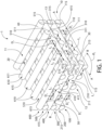
- the present disclosure is directed to a scaffold 1 comprising a multi-layered structure 10.
- the scaffold 1 may be biocompatible.
- the term 'biocompatible' refers to a composition or structure comprising the composition, wherein the composition is compatible with living tissue or a living system by not being toxic, injurious, or physiologically reactive and not causing immunological rejection.
- the scaffold 1 may be biodegradable.
- the term 'biodegradable' refers to a composition or structure comprising the composition that will degrade or erode in vivo to form smaller chemical species.
- the multi-layered structure 10 may comprise a first major surface 11 that is opposite a second major surface 12 as well as a side surface 13 that extends between the first and second major surfaces 11, 12.
- the multi-layered structure 10 may comprise at least an upper layer 40 (also referred to as "uppermost layer”) positioned atop a bottom layer 30 (also referred to as "bottommost layer”) - as discussed further herein.
- the multi-layered structure 10 may further comprise one or more intermediate layers 50 positioned between the bottom layer 30 and the upper layer 40 - as discussed further herein.
- the multi-layered structure 10 of the scaffold 1 may comprise at least a first layer 100 and a second layer 200.
- the multi-layered structure 10 scaffold 1 may comprise a first layer 100, a second layer 200, a third layer 300, a fourth layer 400, a fifth layer 500, and a sixth layer 600.
- the multi-layered structure 10 may comprise a number of layers ranging from 2 to about 30 layers - including all integers and sub-ranges there-between.
- the multi-layered structure 10 may comprise a number of layers ranging from 2 to about 14 layers - including all integers and sub-ranges there-between.
- the multi-layered structure 10 may comprise more than 30 layers.
- the first layer 100 may form the bottom layer 30 of the multi-layered structure 10.
- the upper layer 40 may be at least partially formed by the final layer of the multi-layered structure 10 - whereby the "final layer” refers to highest numbered layer of the multi-layered structure 10.
- the first layer 100 may form the bottom layer 30 and the second layer 200 may form the upper layer 40 because the second layer 200 is the final layer of the multi-layered structure 10 having two (2) layers.
- the first layer 100 may form the bottom layer 30 and the sixth layer 600 may form the upper layer 40 because the sixth layer 600 is the final layer of the multi-layered structure 10 having six (6) layers.
- the layers other than the first layer 100 and the final layer may form the intermediate layers 50 of the multi-layered structure 10.
- the second layer 200, third layer 300, fourth layer 400, and fifth layer 500 may form the intermediate layers 50 - whereby the intermediate layers 50 are positioned between the first and sixth layers 100, 600 - as demonstrated by FIG. 1 .
- the second major surface 12 of the multi-layered structure 10 may form a bottom surface of the multi-layered structure 10 (i.e., the phrases "second major surface” and “bottom surface” may be used interchangeably).
- the first major surface 11 of the multi-layered structure 10 may form an upper surface of the multi-layered structure 10 (i.e., the phrases "first major surface” and "upper surface” may be used interchangeably).
- the second major surface 12 may comprise at least a portion of the first layer 100 such that the first layer 100 may form at least a portion of the bottom surface 12 of the multi-layered structure 10.
- the first major surface 11 may comprise at least a portion of the final layer such that the final layer may form at least a portion of the upper surface 11 of the multi-layered structure 10.
- the side surface 13 may comprise at least a portion of the first layer 100, a portion of the final layer, and a portion of any intermediate layers disposed between the first and final layers.
- each of the layers 100, 200..., etc., that make up the multi-layered structure 10 may comprise a plurality fibers arranged in a substantially parallel array, whereby each fiber extends along an longitudinal axis that intersects opposing terminal ends of that fiber.
- Each fiber may have a fiber diameter D F as measured in a direction orthogonal to the longitudinal axis of the fiber.
- the fiber diameter D F may range from about 40 ⁇ m to about 300 ⁇ m - including all diameters and sub-ranges there-between.
- the fiber diameter D F may remain substantially constant. In other embodiments, for a single layer, the fiber diameter D F may differ from fiber to fiber - as discussed further herein. In other embodiments, the fiber diameter D F of one layer may differ from the fiber diameter D F of a separate layer - as discussed further herein. In other embodiments, the fiber diameter D F may be substantially the same for multiple layers - as discussed further herein.
- each fiber may be substantially parallel to the longitudinal axis of the other fibers in the single layer.
- Each fiber may comprise an outer surface that is offset from the outer surface of an adjacent fiber in a single layer by an offset length L O that remains substantially constant as measured along the longitudinal axis of each fiber.
- the offset length L O may range from about 100 ⁇ m to about 500 ⁇ m - including all distances and sub-ranges there-between.
- the offset length L O between all fibers may remain substantially constant.
- the offset length L O may differ between two different sets of adjacent fibers - as discussed further herein.
- the offset length L O between fibers for one layer may differ from offset length L O of a separate layer - as discussed further herein.
- the offset length L O may be substantially the same for multiple layers - as discussed further herein.
- a ratio may exist between the offset length L O and the fiber diameter D F that ranges from about 1.6:1.0 to about 12.5:1.0 - including all ratios and sub-ranges there-between. In a preferred embodiment, the ratio may range from about 2.5:1 to about 10:1 - including all ratios and sub-ranges there-between.
- the first layer 100 may comprise a plurality first fibers 110 that are arranged in a substantially parallel array, whereby each of the first fibers 110 extends along a first longitudinal axis A-A that intersects opposing terminal ends 115 of the first fiber 110.
- Each first fiber 110 may have a first fiber diameter D 1 as measured in a direction orthogonal to the first longitudinal axis A-A of the first fiber 110.
- the first diameter D 1 may be substantially equal to the fiber diameter D F .
- the first fibers 110 may be arranged such that the first longitudinal axis A-A of each first fiber 110 is substantially parallel to each other.
- Each of the first fibers 110 may comprise an outer surface 111.
- the outer surface 111 of each first fiber 110 may be offset from the outer surface 111 of an adjacent first fiber 110 by a first offset length L 1 .
- the first offset length L 1 as measured between two adjacent first fibers 110 may remain substantially constant as measured along the longitudinal axis A-A of each first fiber 110.
- the first offset length L 1 may be substantially equal to the offset length L O .
- the second 200 may comprise a plurality second fibers 210 that are arranged in a substantially parallel array, whereby each of the second fibers 210 extends along a second longitudinal axis B-B that intersects opposing terminal ends 215 of the second fiber 210.
- Each second fiber 210 may have a second fiber diameter D 2 as measured in a direction orthogonal to the second longitudinal axis B-B of the second fiber 210.
- the second diameter D 2 may be substantially equal to the fiber diameter D F .
- the second fibers 210 may be arranged such that the second longitudinal axis B-B of each second fiber 210 is substantially parallel to each other.
- Each of the second fibers 210 may comprise an outer surface 211.
- the outer surface 211 of each second fiber 210 may be offset from the outer surface 211 of an adjacent second fiber 210 by a second offset length L 2 .
- the second offset length L 2 as measured between two adjacent second fibers 210, may remain substantially constant as measured along the longitudinal axis B-B of each second fiber 210.
- the second offset length L 2 may be substantially equal to the offset length L O .
- the fibers of a single layer may be arranged in a non-parallel relationship to the fibers of an adjacent layer. In other embodiments, the fibers of a single layer may be arranged in a parallel relationship to the fibers of another layer present in the multi-layered structure 10.
- the first fibers 110 of the first layer 100 may be disposed relative to the second fibers 210 of the second layer 200 such that the first longitudinal axis A-A of the first fibers 110 and the second longitudinal axis B-B of the second fibers 210 are in a non-parallel relationship. Specifically, a first intersection angle ⁇ 1 exists between the first and second longitudinal axis A-A, B-B of the first and second fibers 110, 220.
- the first intersection angle ⁇ 1 may range from a value of greater than zero to less than 180° - preferably from at least about 1° to about 179° - including all angles and subranges there-between. In some embodiments, the first intersection angle ⁇ 1 may be 90° making the first and second fibers 110, 210 orthogonal to each other. In other embodiments, the first intersection angle ⁇ 1 may be oblique. In some embodiments, the oblique angle may be acute. In other embodiments, the oblique angle may be obtuse. In some embodiments, the first intersection angle ⁇ 1 may range from about 10° to about 90° - including all angles and sub-ranges there-between.
- the first intersection angle ⁇ 1 may range from about 10° to about 45° - including all angles and sub-ranges there-between. In some embodiments, the first intersection angle ⁇ 1 may be about 10°, 15°, 20°, 25°, 30°, 35°, 40°, 45°, 50°, 55°, 60°, 65°, 70°, 75°, 80°, 85°, or about 90° - including all sub-ranges there-between.
- the combination of the first fibers 110 and the second fibers 210 form an intersecting pattern comprises a cross-hatch geometry having through-holes 20 that extend continuously between the plurality of first fibers 110 and the plurality of second fibers 210.
- the geometry of the through holes 20 of a combined first and second layer 100, 200 may be dictated generally by the first intersection angle ⁇ 1 .
- the through-holes 20 that exist through the combination of the first and second layers 100, 200 will be rectangular - whereby the through hole 20 may either be a square or a non-square rectangle.
- the through holes 20 that exist through the combination of the first and second layers 100, 200 will be a non-rectangular parallelogram.
- the dimensions of the through-hole 20 may be dictated by the first offset length L 1 of the first layer 100 and the second offset length L 2 of the second layer 200.
- the length (or width) of the through-hole 20 may be substantially equal to the first offset length L 1 and the width (or length) of the through-hole 20 may be substantially equal to the second offset length L 2 .
- the resulting through-hole 20 may either a rhombus or square (depending on the first intersection angle ⁇ 1 .
- the resulting through-hole 20 may either be a non-square rectangle or an oblong parallelogram (depending on the first intersection angle ⁇ 1 .
- first layer 100 and second layer 200 provide a fluid pathway that extends throughout the multi-layered structure 10.
- first layer 100 and second layer 200 generally applies to any additional layers (300, 400, 500, 600, etc.) included in the multi-layered structure 10, except with regard to the differences specifically noted below.
- the intermediate layers 50 may comprise one or more of the second layer 200, third layer 300, fourth layer 400, fifth layer 500, sixth layer 600, etc.... layer before the final layer.
- Each of the intermediate layers 50 may comprise a plurality of the respective second fibers 110, third fibers 310, fourth fibers 410, fifth fibers 510, sixth fibers 610, etc. - whereby the foregoing each of the first fibers 110 also applies to the fibers of the intermediate layer 50.
- the multi-layered structure 10 of the present invention may be formed by 3D-printing a scaffold ink-composition (also referred to as an "ink-composition") in a wet-state. After printing, the wet-state ink-composition may be dried into a dry-state, thereby forming each of the first layer 100, second layer 200... the final layer, of the multi-layered structure 10.
- 3D-printing refers to three-dimensional printing techniques that use layering to build three-dimensional articles.
- Each of the first layer 100, second layer 200... etc., to final layer may be formed by one or more continuous passes of a 3D-printer - as discussed further herein.
- the ink-composition may generally comprise a blend of a first polymer and a second polymer.
- the ink-composition may further comprise one or more additives.
- the phrase "wet-state” refers to the ink-composition further comprising a liquid carrier.
- the phrase “dry-state” refers to the ink-composition being substantially free of the liquid carrier. Knowing the amount of liquid carrier present in the ink-composition in the wet-state, the components present in the ink-composition in the dry-state can be used to calculate the corresponding amount of those components in the wet-state ink composition. For example, for a desired dry-state ink-composition that comprises about 50 wt.
- such polymer may be biocompatible.
- the first polymer may be biodegradable.
- the first polymer is a peptide conjugate polymer.
- the peptide conjugate polymer has the structure forth in Formula I: X-Y-Z-Y-X Formula I
- the Z-component is a biocompatible and biodegradable polymer block.
- the Y-component is a linker moiety comprising a maleimide functionalized compound and at least one of a hydroxyl-reactive group, an aromatic group, or an aliphatic chain.
- the X-component is a biologically active peptide block. Covalent bonds are created between the biologically active peptide and the linker moiety as well as between the linker moiety and the biocompatible polymer block.
- the peptide conjugate polymer may be a branched polymer having at least three branches, whereby the terminal groups of each branch comprise a X-component.
- the peptide conjugate polymer may be a substantially linear polymer having the structure of Formula I, whereby at least one X-component is directly pendant off the central region of the biocompatible polymer backbone of the Z-component.
- the biocompatible polymer backbone of Z-component may be a polyester block.
- a non-limiting example of biocompatible polyester may be a polyester derived from a cyclic-ester.
- Non-limiting examples of cyclic-ester include lactones having the Formula II:
- Non-limiting examples of the lactones described above include, but not limited to, caprolactone, t-butyl caprolactone, zeta-enantholactone, deltavalerolactones, the monoalkyl-delta-valerolactones, e.g. the monomethyl-, monoethyl-, monohexyl-deltavalerolactones, and the like; the nonalkyl, dialkyl, and trialkyl-epsilon-caprolactones, e.g.
- beta-lactones e.g., beta-propiolactone, beta-butyrolactone gamma-lactones, e.g., gammabutyrolactone or pivalolactone, dilactones, e.g.
- lactide dilactides, glycolides, e.g., tetramethyl glycolides, and the like, ketodioxanones, e.g. 1,4-dioxan-2-one, 1,5-dioxepan-2-one, and the like.
- the lactones can consist of the optically pure isomers or two or more optically different isomers or can consist of mixtures of isomers.
- the lactone may be ⁇ -caprolactone and its derivatives and other seven membered ring lactones - whereby ⁇ -caprolactone has the formula:
- other monomers may be polymerized with the lactones to comprise the first monomer, such as, for example, one or more compounds which can be polymerized or copolymerized to form aliphatic polyesters or polyester amides or other condensation polymers.
- monomers may include substituted or unsubstituted C 2 -C 8 diols, e.g., ethylene glycol, diethylene glycol, butanediol, neopentyl glycol, and hexanediol.
- the cyclic-ester may be polymerized with a previously formed polyester that is the reaction product of one of the previously discussed C 2 -C 8 diols and a dicarboxylic acids, such as but not limited to, succinic, glutaric or adipic acid; terephthalic acid.
- a dicarboxylic acids such as but not limited to, succinic, glutaric or adipic acid; terephthalic acid.
- the Z-component may be a ethylene glycol initiated poly(caprolactone) ("PCL”) polymer comprising terminal hydroxyl groups having the formula:
- n is an integer ranging from about 40 to about 80 - including all integers and sub-ranges there-between.
- the n value will result in the PCL polymer having a weight-average molecular weight ("MW") ranging from about 10,000 g/mol to about 18,000 g/mol, preferably about 13,000 g/mol to about 16,000 g/mol, including all molecular weights and sub-ranges there-between.
- the weight-average molecular weight of the Z-component may be up to about 45,000 g/mol.
- the Z-component may be poly(caprolactone) ("PCL”) polymer having hydroxyl groups (or other functional groups) present on the backbone of the polymer that are in addition to the terminal groups.
- PCL poly(caprolactone)
- the first polymer may be present in the ink-composition in the dry-state in an amount ranging from about 35% w/v to about 100% w/v - including all amounts and sub-ranges there-between. In some embodiments, the first polymer may be present in the ink-composition in the dry-state in an amount ranging from about 35% w/v to about 65% w/v - including all amounts and sub-ranges there-between. In a preferred embodiment, the first polymer may be present in the ink-composition in the dry-state in an amount ranging from about 35% w/v to about 60% w/v - including all amounts and sub-ranges there-between.
- the linking group that makes up the Y-component may be formed from a linker compound comprising a maleimide group as well as a functional group capable of reacting with the terminal functional groups present on the backbone polymer of the Z-component.
- the linker compound comprises a maleimide group as well as a hydroxyl-reactive group (e.g., carboxylic acid, isocyanate group, and the like).
- the maleimide-containing linker compound may comprise an aromatic group, an aliphatic chain, and combinations thereof.
- linker moiety comprises p-maleimide phenyl isocyanate (“PMPI”) having the formula:
- the isocyanate groups present on the PMPI reacts with the terminal groups present on the polymer backbone of the Y-component.
- the isocyanate groups present on the PMPI react with the hydroxyl terminal groups present on the poly(caprolactone) polymer backbone so form an intermediate polymer comprising maleimide-terminated poly(caprolactone) having two urethane linkages bridging the maleimide groups to the poly(caprolactone) backbone.
- the X-component is a biologically active peptide.
- the biologically active peptide that makes up the X-component may be formed from a peptide compound comprising a functional group capable of reacting with the maleimide functional groups present on the intermediate polymer formed of the Z-component and Y component.
- the peptide compound may comprise a thiol group.
- the peptide compound may be amine-functionalized.
- the thiol group present on the peptide compound reacts with the terminal maleimide groups present on the intermediate polymer so as to form a peptide-terminated peptide-polymer conjugate having two urethane linkages bridged together by a poly(caprolactone) backbone.
- the biologically active peptide is formed from a thiol functional peptide.
- Thiol functional peptide may be a cysteine containing peptide.
- the peptide may include hyaluronic binding, mineralizing, and cell adhesion peptides.
- the amino acid sequence of each peptide may be tailorable and can therefore be designed for a desired application.
- the X-component of the present invention may include peptides having about 5 to about 30 amino acids in length.
- the peptide may be selected from CGGGAAAEEE and/or CGGGRYPISRPRKR as being suitable to promote mineralization and hyaluronic acid binding.
- the ink-composition may further comprise a second polymer.
- the second polymer may be biocompatible.
- the second polymer may be biodegradable.
- the second polymer may be a polyester polymer.
- the polyester polymer may be derived from one or more of the cyclic-esters disclosed as being suitable for the Z-component.
- the second polymer may be poly(caprolactone) that is substantially free of peptide conjugation.
- the second polymer may be substantially free of peptide groups.
- the second polymer may be a poly(caprolactone) homopolymer.
- the second polymer may have a weight average molecular weight M W ranging from about 10,000 g/mol to about 400,000 g/mol - including all weight average molecular weights M W and subranges there-between.
- the second polymer may be present in the ink-composition in the dry-state in an amount ranging from about 0 % w/v to about 65% w/v - including all amounts and sub-ranges there-between. In some embodiments, the second polymer may be present in the ink-composition in the dry-state in an amount ranging from about 35% w/v to about 65% w/v - including all amounts and sub-ranges there-between. In some embodiments, the second polymer may be present in the ink-composition in the dry-state in an amount ranging from about 40% w/v to about 65% w/v - including all amounts and sub-ranges there-between.
- the first polymer and the second polymer may be physically blended together in the ink-composition.
- the first polymer and the second polymer may be present together in weight ratio ranging from about 1:2 to about 5:1 - including all weight ratios and sub-ranges there-between. In other embodiments, the first polymer and the second polymer may be present together in weight ratio ranging from about 1:2 to about 3:1 - including all weight ratios and sub-ranges there-between.
- the ink-composition may comprise a liquid carrier.
- the liquid carrier may be a solvent.
- solvent include volatile solvent (as measured at room temperature).
- Volatile solvent may be selected from one or more of water; dichloromethane ("DCM”); hexafluoro-1-propanol ("HFIP"); methanol; ethanol; propanol; isopropyl alcohol; acetone; isobutene; pentane; hexane; dimethyl ether; methyl ethyl ketone; diethyl ether; 1,1, difluoroethane; 1,1,1,2 tetrafluorethane; 1,1,1,2,3,3,3-heptafluoropropane; 1,1,1,3,3,3 hexafluoropropane; ethyl acetate; or combinations thereof.
- DCM dichloromethane
- HFIP hexafluoro-1-propanol
- methanol ethanol
- the volatile solvent system can include iso-amyl acetate, denatured alcohol, chlorobutanol, turpentine, cytopentasiloxane, cyclomethicone, or combinations thereof.
- the volatile solvent may be selected from methylene chloride; acetic acid; ethyl acetoacetate; dimethylsulfoxide; n-methyl pyrrolidone; 2-amino-2-methyl-1-propanol; 1-amino-2-propanol; 2-dimethylamino-2-methyl-1-propanol; N,N-diethylethanolamine; N-methyldiethanolamine; N,N-dimethylethanolamine; triethanolamine; 2-aminoethanol; 1-[bis[3-(dimethylamino)propyl]amino]-2-propanol; 3-amino-1-propanol; 2-(2-aminoethylamino)ethanol; tris(hydroxymethyl)amin
- the liquid carrier may be present in the ink-composition in the wet-state in an amount ranging from about 5% w/v to about 95% w/v - including all amounts and sub-ranges there-between.
- the 3D-printing process may comprise a printing system 5 that includes a 3D-printer 6 and a support substrate 7 on which the 3D-printing occurs.
- the 3D-printer 6 may comprise at least one reservoir comprising the ink-composition as well as a printing head 8 that ejects the ink-composition from the reservoir 9 onto the support substrate 7 to form the first layer 100. Subsequent layers may be applied atop the first layer 100.
- the second layer 200 is printed atop the first layer 100, which has been printed atop the support substrate 7.
- the substrate 7 may be glass.
- the printing head 8 may be in the form of an adjustable nozzle that directs the wet-state ink-composition from the reservoir 9 in a control manner, thereby controlling fiber diameter D F .
- the 3D-printing process may use pneumatic extrusion to direct (i.e., extrude) the wet-state ink composition through a needle nozzle to form each fiber of each layer.
- the printer 6 is mounted onto at least a moveable three-dimensional support axis (X,Y,Z) allowing the printing head 8 to achieve precise placement within the printing system 5 during printing.
- the 3D-printing process may also use extrusion speed and/or needle gauge to further provide precise control over fiber diameter D F , offset length L O between adjacent fibers of a single layer, as well as the orientation of fibers within one layer relative to the orientation of fiber within an adjacent layer.
- the precise placement of each fiber within each layer provides the ability to fine tune the porosity of the resulting multi-layered structure 10, thereby fine tuning the porosity of the scaffold 1.
- the liquid carrier may evaporate, thereby transforming the wet-state ink composition into the dry-state ink-composition.
- the dry-state ink composition may form the multi-layered structure 10 of the present invention. Evaporation of the liquid carrier from the wet-state ink composition may be performed under atmospheric conditions - i.e., 1 atm and room temperature (about 70 °F). In other embodiments, one or more heaters may be used to help accelerate the evaporation of the liquid carrier from the wet-state ink composition.
- the wet-state ink composition may within the reservoir 9 at room temperature, whereby 3D-printing of the wet-state ink composition is performed at room temperature.
- the wet-state ink composition may be heated within the reservoir 9 to an elevated temperature that is above room temperature, whereby 3D-printing of the wet-state ink composition is performed at the elevated temperature.
- the wet-state ink composition may be heated within the reservoir 9 and 3D-printed at an elevated temperature ranging from about 25 °C to about 200 °C - including all temperatures and sub-ranges there-between.
- the wet-state ink composition may be within the reservoir 9 and 3D-printed at room temperature.
- the peptide-conjugation of the first polymer presents the functionality on the surface of the multi-layered structure 10 without the need of additional functionalization steps, thereby resulting in the 3D-printed multi-layered structure 10 being suitable as the scaffold 1 of the present invention without further need of surface modifying chemistries. Additionally, by varying the concentration of conjugate added, the local concentration of peptides presented on the surface of each layer within a multi-layered structure 10 and resulting scaffold 1 can be controlled.
- the resulting multi-layered structure 10 may be composed of any number of peptide-modified polymer ink compositions, each having different peptide sequences and varying spatial concentrations, whereby changing the orientation, distribution, and diameter of the printed fibers allows for regional control of physical properties across the scaffold.
- the printing system 5 may comprise two or more 3D-printers 6 or a single 3D-printer 6 having two or more reservoirs 9, whereby each reservoir contains a different ink composition.
- a first reservoir 9 may comprise a first ink composition having a first concentration of a first polymer and a second polymer and a second reservoir 9 may comprise a second ink composition having a second concentration of the first polymer and the second polymer, whereby the first and second polymers of the first and second ink compositions are the same chemically, but the first and second concentrations of the first and second ink compositions are not equal.
- a first reservoir 9 may comprise a first ink composition having a first polymer and a second polymer and a second reservoir 9 may comprise a second ink composition having a first polymer and a second polymer, whereby the first polymer of the first ink composition and the first polymer of the second ink composition are chemically distinct.
- the concentrations of the first polymer in each of the first ink composition and second ink composition may be the same or different.
- the phrase “chemically distinct” may refer to the first polymer having different peptide groups present in the X-component of the first polymer. In a non-limiting example, the phrase “chemically distinct” may refer to the first polymer having different linker chemistries in the Y-component of the first polymer. In a non-limiting example, the phrase “chemically distinct” may refer to the first polymer having different polymer backbone chemistry in the Z-component of the first polymer. In a non-limiting example, the phrase “chemically distinct” may refer to the first polymer having different molecular weights within the Z-component of the first polymer.
- the phrase "chemically distinct" may refer to varying amounts of the X-component bonded to polymer backbone of the Z-component - e.g., only two terminal peptide groups vs. three or more peptide groups present along the polymer back bone of the Z-component of the first polymer.
- 3D-printing ink compositions comprising first polymer - as well as second polymer - allows for the fabrication of scaffolds for tissue engineering that resemble native tissue organization to guide functional tissue regeneration.
- the resulting scaffolds 1 are suitable as biomaterials for tissue engineering that can promote tissue regeneration and restore or replace diseased or damaged tissues.
- the porous, biodegradable scaffolds 1 are used to provide mechanical support during the early stages of regeneration while also allowing for cell infiltration and nutrient diffusion .
- targeted control over placement of peptide conjugation within each layer 100, 200, etc.... results in the scaffold 1 having a hierarchical structure that combines multiple components together to perform functions that could not be achieved by each component alone. Therefore, scaffolds 1 can be designed to match gradients in biochemical and biophysical properties that exist in numerous tissues, including those of the musculoskeletal, cardiovascular, and neural systems.
- articular cartilage is a musculoskeletal tissue that covers the ends of long bones to facilitate low-friction movement while distributing mechanical loads. This tissue exhibits depth-dependent gradients in structure, cell type, and ECM components, leading to anisotropic mechanical properties that are critical for biomechanical function.
- Cartilage serves as just one example of a complex tissue that exhibits essential intrinsic gradients in structure and function that provides a guiding inspiration for the design of new biomaterials.
- a non-limiting example will be provided for a scaffold 1000 having hierarchical structure that may be designed to match gradients of biochemical and biophysical properties that exist in tissues.
- the scaffold 1000 is similar to the scaffold 1 except as described herein below.
- the description of the scaffold 1 above generally applies to the scaffold 1000 described below except with regard to the differences specifically noted below.
- a similar numbering scheme will be used for the scaffold 1000 as with the scaffold 1, except that the 1000-series of numbers will be used.
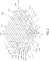
- the scaffold 1000 may comprise a multi-layered structure 1010 having at least a first layer 1100 and a second layer 1200.
- the first fibers 1110 of the first layer 1100 may have a first fiber diameter D 1 and the second fibers 1210 of the second layer 1200 may have a second fiber diameter D 2 - whereby the first and second fiber diameters D 1 , D 2 are not equal.
- the first fiber diameter D 1 may be substantially constant within the first layer 1100.
- the second fiber diameter D 2 may be substantially constant within the second layer 1200.
- first fibers 1110 of the first layer 1100 may be offset from each other by a first offset length L 1 and the second fibers 1210 of the second layer 1200 may be offset from each other by a second offset length L 2 - whereby the first and second offset lengths L 1 , L 2 are not equal.
- the offset length L 1 may be substantially constant within the first layer 1100.
- the second offset length L 2 may be substantially constant within the second layer 1200.
- the first fibers 1110 and the second fibers 1210 may overlap at a plurality of intersection points, whereby the plurality of intersection points across multiple layers 1100, 1200, 1300, 1400, 1500, 1600, etc., overlap such that the through holes 1020 extend continuously from the first major surface 1011 to the second major surface 1012 of the multi-layered structure 1010.
- the first fibers 1110 and the second fibers 1210 may overlap at a first plurality of intersection points
- the second fibers 1210 and third fibers 1310 may overlap at a plurality of second intersection points, whereby the first and second plurality of intersection points do not overlap (not pictured in FIG. 2 ).
- a non-limiting example will be provided for a scaffold 2000 having hierarchical structure that may be designed to match gradients of biochemical and biophysical properties that exist in tissues.
- the scaffold 2000 is similar to the scaffolds 1 and 1000 except as described herein below.
- the description of the scaffold 1 and 1000 above generally applies to the scaffold 2000 described below except with regard to the differences specifically noted below.
- a similar numbering scheme will be used for the scaffold 2000 as with the scaffold 1, except that the 2000-series of numbers will be used.
- the scaffold 1000 may comprise a multi-layered structure 2010 having at least a first layer 2100 and a second layer 2200.
- the first layer 2100 may comprise a first set of fibers 2110A, 2110B, 2110C, 2110D, 2110E that each have their own first fiber diameter D 1A D 1B D 1C D 1D D 1E ... etc.
- the first fiber diameter D 1A D 1B D 1C D 1D D 1E ... etc. of each of the first fibers 2110A, 2110B, 2110C, 2110E, 2110E may vary within the first layer 2100.
- the second layer 2200 may also comprise a second set of fibers that each have their own second fiber diameter, whereby the second fiber diameter of each of the second fibers may vary within the first layer 2100.
- at least one of the first fibers 2110A may be equal to at least one of the second fibers.
- the first set of fibers 2110A, 2110B, 2110C, 2110D, 2110E, etc. may be arranged such that the first fiber diameter D 1A , D 1B , D 1C , D 1D , D 1E ... etc. increase in size forming an enlarging array of first fibers 2110A, 2110B, 2110C, 2110D, 2110E, etc. when moving in a single direction across the first layer 2100.
- there may be a corresponding decrease in size of the offset length L 1A , L 1B , L 1C , L 1D , L 1E ... etc. between adjacent first fibers 2110A, 2110B, 2110C, 2110D, 2110E, etc. such that the dimension of through holes 2020A, 2020B, 2020C, 2020D, etc. decrease in size when moving along the single direction across the first layer 2100.
- Each of the second layer 2200, third layer 2300, fourth layer 2400, fifth layer 2500, sixth layer 2600, etc. may also exhibit the same fiber diameter and offset length relationship as the first layer 2100 of this embodiment.
- a non-limiting example will be provided for a scaffold 3000 having hierarchical structure that may be designed to match gradients of biochemical and biophysical properties that exist in tissues.
- the scaffold 3000 is similar to the scaffolds 1, 1000, 2000 except as described herein below.
- the description of the scaffold 1 above generally applies to the scaffold 3000 described below except with regard to the differences specifically noted below.
- a similar numbering scheme will be used for the scaffold 3000 as with the scaffold 1, except that the 3000-series of numbers will be used.
- the scaffold 3000 may comprise a multi-layered structure 3010 having at least a first layer 3100 and a second layer 3200.
- the first layer 2100 may comprise first fibers 3110 and the second layer 2200 may comprise second fibers 3210.
- the first fibers 3110 of the first layer 3100 may be disposed relative to the second fibers 3210 of the second layer 3200 such that the first longitudinal axis A-A of the first fibers 3110 and the second longitudinal axis B-B of the second fibers 3210 are in a non-parallel relationship.
- a first intersection angle ⁇ 1 exists between the first and second longitudinal axis A-A, B-B of the first and second fibers 3110, 3220.
- the first intersection angle ⁇ 1 may range from a value of greater than zero to less than 180° - preferably from at least about 1° to about 89° - including all angles and subranges there-between. In some embodiments, the first intersection angle ⁇ 1 may be from about 10° to about 45° - including all angles and sub-ranges there-between. In some embodiments, the first intersection angle ⁇ 1 may be about 10°, 15°, 20°, 25°, 30°, 35°, 40°, 45°, 50°, 55°, 60°, 65°, 70°, 75°, 80°, 85°, or about 90° - including all sub-ranges there-between. According to this embodiment, the through holes 2020 form non-rectangular parallelograms
- a non-limiting example will be provided for a scaffold 4000 having hierarchical structure that may be designed to match gradients of biochemical and biophysical properties that exist in tissues.
- the scaffold 4000 is similar to the scaffolds 1, 1000, 2000, and 3000 except as described herein below.
- the description of the scaffold 1, 1000, 2000, and 3000 above generally applies to the scaffold 4000 described below except with regard to the differences specifically noted below.
- a similar numbering scheme will be used for the scaffold 4000 as with the scaffold 1, except that the 4000-series of numbers will be used.
- the scaffold 4000 may comprise a multi-layered structure 4010 having at least a first layer 4100, a second layer 4200, and a third layer 4600.
- the first fibers 4110 of the first layer 4100 may be disposed relative to the second fibers 4210 of the second layer 4200 such that the first longitudinal axis A-A of the first fibers 4110 and the second longitudinal axis B-B of the second fibers 4210 intersect at a first intersection angle ⁇ 1 .
- the first fibers 4110 of the first layer 4100 may be disposed relative to the third fibers 4610 of the third layer 4600 such that the first longitudinal axis A-A of the first fibers 4110 and the third longitudinal axis C-C of the third fibers 4610 intersect at a second intersection angle ⁇ 1 .
- the first and second intersection angles ⁇ 1 , ⁇ 2 may be selected from any value that is of greater than zero to less than 180° - preferably from at least about 1° to about 90° - including all angles and subranges there-between - so long as the first intersection angle ⁇ 1 and the second intersection angle ⁇ 1 are not equal.
- the first fibers 4110 and the second fibers 4210 may overlap at a plurality of first intersect points, and the first fibers 1210 and third fibers 4610 may overlap at a plurality of second intersection points, whereby the first and second plurality of intersection points do not overlap.
- at least a first through hole 4020a is formed by the overlap of the first fibers 4110 and the second fibers 4210 and a second through hole 4020b is formed by the overlap of the first fibers 4110 and the third fibers 4610 - whereby the first and second through holes 4020a, 4020b have different geometry (e.g., square vs. rhombus).
Landscapes
- Health & Medical Sciences (AREA)
- Chemical & Material Sciences (AREA)
- Engineering & Computer Science (AREA)
- Life Sciences & Earth Sciences (AREA)
- Medicinal Chemistry (AREA)
- Materials Engineering (AREA)
- Epidemiology (AREA)
- Dermatology (AREA)
- Oral & Maxillofacial Surgery (AREA)
- Transplantation (AREA)
- Animal Behavior & Ethology (AREA)
- General Health & Medical Sciences (AREA)
- Public Health (AREA)
- Veterinary Medicine (AREA)
- Manufacturing & Machinery (AREA)
- Chemical Kinetics & Catalysis (AREA)
- Biomedical Technology (AREA)
- Molecular Biology (AREA)
- Physics & Mathematics (AREA)
- Mechanical Engineering (AREA)
- Optics & Photonics (AREA)
- Dispersion Chemistry (AREA)
- Materials For Medical Uses (AREA)
Description
- This application claims the benefit of priority from
United States Provisional Patent Application No. 62/535,955, filed July 23, 2017 - Osteoarthritis is a degenerative condition that impacts over 70% of adults over the age of 65. This disease is characterized by a painful breakdown of the articular cartilage that covers the bone ends and lubricates the motion of the joints. Currently, treatment for end-stage osteoarthritis is arthroplasty, or total joint replacement. More than 50% of total joint replacement patients are under age 65, presenting a significant challenge to the health system because these patients are expected to outlive their implants and may require one or more revision procedures over their lifetime. The cost of this care presents a staggering economic burden. The financial burden of joint replacement and the individual patient hardship during the painful rehabilitation period provide significant motivation to repair and regenerate cartilage tissue. Thus, there exists a need for a new approach at treating osteoarthritis as well as other orthopedic related ailments.
- W. Lesley et al. [ADVANCED HEALTHCARE MATERIALS, 3(9), 01-09-2014, 1381-1386, XP055567155] disclose scaffolds fabricated by co-electrospinning solutions comprising poly(ε-caprolactone) and peptide-polymer conjugates.
- The invention is defined by the claims. Any subject matter falling outside the scope of the claims is provided for information purposes only.
- The present invention is directed to a 3D-printed scaffold comprising a peptide-polymer conjugate, the peptide-polymer conjugate having the structure: X-Y-Z-Y-X; wherein X is a biologically active peptide, Y is a linker moiety comprising a maleimide functionalized compound and at least one of a hydroxyl-reactive group, an aromatic group, or an aliphatic chain, and Z is a biocompatible and biodegradable polymer.
- In other embodiments, the present invention is directed to the above implantable scaffold comprising: a first layer formed of a plurality of first fibers oriented in a first direction; and a second layer formed of a plurality of second fibers oriented in a second direction; wherein the first direction and the second direction are different and the pluralities of first and second fibers comprise peptide-polymer conjugate.
- The present invention is also directed to a method of forming the above implantable scaffold comprising: a) 3D-printing a plurality of first fibers in a first direction to form a first layer; b) 3D-printing a plurality of second fibers in a second direction atop the first layer to form a second layer, wherein the first and second directions are different, wherein the plurality of first fibers have a first fiber diameter and the plurality of second fibers have a second fiber diameter, whereby the first fiber diameter and the second fiber diameter are not equal; wherein the first and second fibers comprise peptide-polymer conjugate.
- Further areas of applicability of the present invention will become apparent from the detailed description provided hereinafter. It should be understood that the detailed description and specific examples, are intended for purposes of illustration only and are not intended to limit the scope of the invention.
- The present invention will become more fully understood from the detailed description and the accompanying drawings, wherein:
-
FIG. 1 is a perspective close-up view of a scaffold according to one embodiment of the present invention; -
FIG. 2 is a perspective close-up view of a scaffold according to one embodiment of the present invention; -
FIG. 3 is a perspective close-up view of a scaffold according to one embodiment of the present invention; -
FIG. 4A is a perspective close-up view of a scaffold according to one embodiment of the present invention; -
FIG. 4B is a perspective close-up view of a scaffold according to one embodiment of the present invention; -
FIG. 4C is a perspective close-up view of a scaffold according to one embodiment of the present invention; -
FIG. 5 is a perspective close-up view of a scaffold according to one embodiment of the present invention; and -
FIG. 6 is a perspective close-up view of a manufacturing process of the scaffold according to one embodiment of the present invention. - The following description of the preferred embodiment(s) is merely exemplary in nature and is in no way intended to limit the invention, its application, or uses.
- As used throughout, ranges are used as shorthand for describing each and every value that is within the range. Any value within the range can be selected as the terminus of the range. In the event of a conflict in a definition in the present disclosure and that of a cited reference, the present disclosure controls.
- Unless otherwise specified, all percentages and amounts expressed herein and elsewhere in the specification should be understood to refer to percentages by weight. The amounts given are based on the active weight of the material.
- The description of illustrative embodiments according to principles of the present invention is intended to be read in connection with the accompanying drawings, which are to be considered part of the entire written description. In the description of embodiments of the invention disclosed herein, any reference to direction or orientation is merely intended for convenience of description and is not intended in any way to limit the scope of the present invention. Relative terms such as "lower," "upper," "horizontal," "vertical," "above," "below," "up," "down," "top," and "bottom" as well as derivatives thereof (e.g., "horizontally," "downwardly," "upwardly," etc.) should be construed to refer to the orientation as then described or as shown in the drawing under discussion. These relative terms are for convenience of description only and do not require that the apparatus be constructed or operated in a particular orientation unless explicitly indicated as such.
- Terms such as "attached," "affixed," "connected," "coupled," "interconnected," and similar refer to a relationship wherein structures are secured or attached to one another either directly or indirectly through intervening structures, as well as both movable or rigid attachments or relationships, unless expressly described otherwise. Moreover, the features and benefits of the invention are illustrated by reference to the exemplified embodiments. Accordingly, the invention expressly should not be limited to such exemplary embodiments illustrating some possible non-limiting combination of features that may exist alone or in other combinations of features; the scope of the invention being defined by the claims appended hereto.
- Unless otherwise specified, all percentages and amounts expressed herein and elsewhere in the specification should be understood to refer to percentages by weight. The amounts given are based on the active weight of the material. According to the present application, the term "about" means +/- 5% of the reference value. According to the present application, the term "substantially free" less than about 0.1 wt. % based on the total of the referenced value.
- The present disclosure is directed to peptide-polymer conjugates, methods of their production, as well as musculoskeletal tissue engineering that comprise the peptide polymer conjugates. In some embodiments, the peptide-polymer conjugates of the present disclosure are used in the design and manufacture of cell-free scaffolds for regeneration of musculoskeletal tissues and interfaces. The scaffolds of the present disclosure may suitable for, but are not limited to, implantation in cartilage, bone, tendon, ligament, fibrous joints, or connective tissue, and boundary zones between. Tissues. In a non-limiting example, the scaffold may be implantable into a bound zone between tissue that includes the osteochondral zone, which refers to the transition region from cartilage to underlying bone. Other cell-free scaffold-based tissue engineering applications may extend beyond the musculoskeletal system
- The peptide-polymer conjugates and 3D-printed scaffolds formed thereof may also be suitable for cell-based therapies, such as mesenchymal stem cells that are harvested and cultured within the scaffold, followed by autologous re-implantation - as discussed further herein.
- Referring now to
FIG. 1 , the present disclosure is directed to a scaffold 1 comprising amulti-layered structure 10. The scaffold 1 may be biocompatible. The term 'biocompatible' refers to a composition or structure comprising the composition, wherein the composition is compatible with living tissue or a living system by not being toxic, injurious, or physiologically reactive and not causing immunological rejection. The scaffold 1 may be biodegradable. The term 'biodegradable' refers to a composition or structure comprising the composition that will degrade or erode in vivo to form smaller chemical species. - The
multi-layered structure 10 may comprise a firstmajor surface 11 that is opposite a secondmajor surface 12 as well as aside surface 13 that extends between the first and secondmajor surfaces multi-layered structure 10 may comprise at least an upper layer 40 (also referred to as "uppermost layer") positioned atop a bottom layer 30 (also referred to as "bottommost layer") - as discussed further herein. In some embodiments, themulti-layered structure 10 may further comprise one or moreintermediate layers 50 positioned between thebottom layer 30 and the upper layer 40 - as discussed further herein. - The
multi-layered structure 10 of the scaffold 1 may comprise at least afirst layer 100 and asecond layer 200. In the non-limiting exemplified embodiment ofFIG. 1 , themulti-layered structure 10 scaffold 1 may comprise afirst layer 100, asecond layer 200, athird layer 300, afourth layer 400, afifth layer 500, and asixth layer 600. In other embodiments, themulti-layered structure 10 may comprise a number of layers ranging from 2 to about 30 layers - including all integers and sub-ranges there-between. In other embodiments, themulti-layered structure 10 may comprise a number of layers ranging from 2 to about 14 layers - including all integers and sub-ranges there-between. In other embodiments, themulti-layered structure 10 may comprise more than 30 layers. - The
first layer 100 may form thebottom layer 30 of themulti-layered structure 10. As discussed further herein, theupper layer 40 may be at least partially formed by the final layer of the multi-layered structure 10 - whereby the "final layer" refers to highest numbered layer of themulti-layered structure 10. - In a non-limiting example, when a total of two (2) layers (i.e., a
first layer 100 and a second layer 200) are used to form themulti-layered structure 10, thefirst layer 100 may form thebottom layer 30 and thesecond layer 200 may form theupper layer 40 because thesecond layer 200 is the final layer of themulti-layered structure 10 having two (2) layers. - In another non-limiting example that is demonstrated by
FIG. 1 , when a total of six (6) layers (i.e., afirst layer 100, asecond layer 200, athird layer 300, afourth layer 400, afifth layer 500, and a sixth layer 600) are used to form themulti-layered structure 10, thefirst layer 100 may form thebottom layer 30 and thesixth layer 600 may form theupper layer 40 because thesixth layer 600 is the final layer of themulti-layered structure 10 having six (6) layers. - When three or more layers are used to form the
multi-layered structure 10, the layers other than thefirst layer 100 and the final layer may form theintermediate layers 50 of themulti-layered structure 10. In a non-limiting example, when a total of six (6) layers are used to form themulti-layered structure 10, thesecond layer 200,third layer 300,fourth layer 400, andfifth layer 500 may form the intermediate layers 50 - whereby theintermediate layers 50 are positioned between the first andsixth layers 100, 600 - as demonstrated byFIG. 1 . - The second
major surface 12 of themulti-layered structure 10 may form a bottom surface of the multi-layered structure 10 (i.e., the phrases "second major surface" and "bottom surface" may be used interchangeably). The firstmajor surface 11 of themulti-layered structure 10 may form an upper surface of the multi-layered structure 10 (i.e., the phrases "first major surface" and "upper surface" may be used interchangeably). - The second
major surface 12 may comprise at least a portion of thefirst layer 100 such that thefirst layer 100 may form at least a portion of thebottom surface 12 of themulti-layered structure 10. The firstmajor surface 11 may comprise at least a portion of the final layer such that the final layer may form at least a portion of theupper surface 11 of themulti-layered structure 10. Theside surface 13 may comprise at least a portion of thefirst layer 100, a portion of the final layer, and a portion of any intermediate layers disposed between the first and final layers. - As discussed in greater detail herein, each of the
layers multi-layered structure 10 may comprise a plurality fibers arranged in a substantially parallel array, whereby each fiber extends along an longitudinal axis that intersects opposing terminal ends of that fiber. Each fiber may have a fiber diameter DF as measured in a direction orthogonal to the longitudinal axis of the fiber. The fiber diameter DF may range from about 40 µm to about 300 µm - including all diameters and sub-ranges there-between. - For a single layer, the fiber diameter DF may remain substantially constant. In other embodiments, for a single layer, the fiber diameter DF may differ from fiber to fiber - as discussed further herein. In other embodiments, the fiber diameter DF of one layer may differ from the fiber diameter DF of a separate layer - as discussed further herein. In other embodiments, the fiber diameter DF may be substantially the same for multiple layers - as discussed further herein.
- For any single layer, the longitudinal axis of each fiber may be substantially parallel to the longitudinal axis of the other fibers in the single layer. Each fiber may comprise an outer surface that is offset from the outer surface of an adjacent fiber in a single layer by an offset length LO that remains substantially constant as measured along the longitudinal axis of each fiber. The offset length LO may range from about 100 µm to about 500 µm - including all distances and sub-ranges there-between.
- For a single layer, the offset length LO between all fibers may remain substantially constant. In other embodiments, for a single layer, the offset length LO may differ between two different sets of adjacent fibers - as discussed further herein. In other embodiments, the offset length LO between fibers for one layer may differ from offset length LO of a separate layer - as discussed further herein. In other embodiments, the offset length LO may be substantially the same for multiple layers - as discussed further herein.
- For each single layer, a ratio may exist between the offset length LO and the fiber diameter DF that ranges from about 1.6:1.0 to about 12.5:1.0 - including all ratios and sub-ranges there-between. In a preferred embodiment, the ratio may range from about 2.5:1 to about 10:1 - including all ratios and sub-ranges there-between.
- In one embodiment, the
first layer 100 may comprise a pluralityfirst fibers 110 that are arranged in a substantially parallel array, whereby each of thefirst fibers 110 extends along a first longitudinal axis A-A that intersects opposing terminal ends 115 of thefirst fiber 110. Eachfirst fiber 110 may have a first fiber diameter D1 as measured in a direction orthogonal to the first longitudinal axis A-A of thefirst fiber 110. The first diameter D1 may be substantially equal to the fiber diameter DF. - The
first fibers 110 may be arranged such that the first longitudinal axis A-A of eachfirst fiber 110 is substantially parallel to each other. Each of thefirst fibers 110 may comprise anouter surface 111. Within thefirst layer 100, theouter surface 111 of eachfirst fiber 110 may be offset from theouter surface 111 of an adjacentfirst fiber 110 by a first offset length L1. The first offset length L1 as measured between two adjacentfirst fibers 110 may remain substantially constant as measured along the longitudinal axis A-A of eachfirst fiber 110. The first offset length L1 may be substantially equal to the offset length LO. - In one embodiment, the second 200 may comprise a plurality
second fibers 210 that are arranged in a substantially parallel array, whereby each of thesecond fibers 210 extends along a second longitudinal axis B-B that intersects opposing terminal ends 215 of thesecond fiber 210. Eachsecond fiber 210 may have a second fiber diameter D2 as measured in a direction orthogonal to the second longitudinal axis B-B of thesecond fiber 210. The second diameter D2 may be substantially equal to the fiber diameter DF. - The
second fibers 210 may be arranged such that the second longitudinal axis B-B of eachsecond fiber 210 is substantially parallel to each other. Each of thesecond fibers 210 may comprise anouter surface 211. Within thesecond layer 200, theouter surface 211 of eachsecond fiber 210 may be offset from theouter surface 211 of an adjacentsecond fiber 210 by a second offset length L2. The second offset length L2, as measured between two adjacentsecond fibers 210, may remain substantially constant as measured along the longitudinal axis B-B of eachsecond fiber 210. The second offset length L2 may be substantially equal to the offset length LO. - The fibers of a single layer may be arranged in a non-parallel relationship to the fibers of an adjacent layer. In other embodiments, the fibers of a single layer may be arranged in a parallel relationship to the fibers of another layer present in the
multi-layered structure 10. - In a non-limiting example, the
first fibers 110 of thefirst layer 100 may be disposed relative to thesecond fibers 210 of thesecond layer 200 such that the first longitudinal axis A-A of thefirst fibers 110 and the second longitudinal axis B-B of thesecond fibers 210 are in a non-parallel relationship. Specifically, a first intersection angle Θ1 exists between the first and second longitudinal axis A-A, B-B of the first andsecond fibers 110, 220. - The first intersection angle Θ1 may range from a value of greater than zero to less than 180° - preferably from at least about 1° to about 179° - including all angles and subranges there-between. In some embodiments, the first intersection angle Θ1 may be 90° making the first and
second fibers - With the
first layer 100 and thesecond layer 200 being arranged in a non-parallel relationship, the combination of thefirst fibers 110 and thesecond fibers 210 form an intersecting pattern comprises a cross-hatch geometry having through-holes 20 that extend continuously between the plurality offirst fibers 110 and the plurality ofsecond fibers 210. The geometry of the throughholes 20 of a combined first andsecond layer - In a non-limiting example, when the first intersection angle Θ1 is a right angle the through-
holes 20 that exist through the combination of the first andsecond layers hole 20 may either be a square or a non-square rectangle. In a non-limiting example, when the first intersection angle Θ1 oblique, the throughholes 20 that exist through the combination of the first andsecond layers - The dimensions of the through-
hole 20 may be dictated by the first offset length L1 of thefirst layer 100 and the second offset length L2 of thesecond layer 200. For instance, the length (or width) of the through-hole 20 may be substantially equal to the first offset length L1 and the width (or length) of the through-hole 20 may be substantially equal to the second offset length L2. - According to some embodiments, when the first offset length L1 of the
first layer 100 is substantially equal to the second offset length L2 of thesecond layer 200, the resulting through-hole 20 may either a rhombus or square (depending on the first intersection angle Θ1. However, when the first offset length L1 of thefirst layer 100 is not equal to the second offset length L2 of thesecond layer 200, the resulting through-hole 20 may either be a non-square rectangle or an oblong parallelogram (depending on the first intersection angle Θ1. - As discussed in greater detail herein, the presence of the through-
hole 20 for a combined first andsecond layer multi-layered structure 10. As addressed further herein, the discussion with respect to thefirst layer 100 andsecond layer 200 above generally applies to any additional layers (300, 400, 500, 600, etc.) included in themulti-layered structure 10, except with regard to the differences specifically noted below. - Additionally, the
intermediate layers 50 may comprise one or more of thesecond layer 200,third layer 300,fourth layer 400,fifth layer 500,sixth layer 600, etc.... layer before the final layer. Each of theintermediate layers 50 may comprise a plurality of the respectivesecond fibers 110,third fibers 310,fourth fibers 410,fifth fibers 510,sixth fibers 610, etc. - whereby the foregoing each of thefirst fibers 110 also applies to the fibers of theintermediate layer 50. - Referring now to
FIG. 6 , themulti-layered structure 10 of the present invention may be formed by 3D-printing a scaffold ink-composition (also referred to as an "ink-composition") in a wet-state. After printing, the wet-state ink-composition may be dried into a dry-state, thereby forming each of thefirst layer 100,second layer 200... the final layer, of themulti-layered structure 10. The term "3D-printing" refers to three-dimensional printing techniques that use layering to build three-dimensional articles. Each of thefirst layer 100,second layer 200... etc., to final layer may be formed by one or more continuous passes of a 3D-printer - as discussed further herein. - As discussed in greater detail herein, the ink-composition may generally comprise a blend of a first polymer and a second polymer. In some embodiments, the ink-composition may further comprise one or more additives. The phrase "wet-state" refers to the ink-composition further comprising a liquid carrier. The phrase "dry-state" refers to the ink-composition being substantially free of the liquid carrier. Knowing the amount of liquid carrier present in the ink-composition in the wet-state, the components present in the ink-composition in the dry-state can be used to calculate the corresponding amount of those components in the wet-state ink composition. For example, for a desired dry-state ink-composition that comprises about 50 wt. % of the first polymer, whereby that ink-composition is to be applied by 3D-printing in the wet-state with 30 wt. % of liquid carrier, the corresponding amount of the first polymer in the wet-state ink composition would be about 35 wt. % based on the total weight of the ink composition in the wet-state - i.e., (100 wt. % - 30 wt. %) x 50 wt. % = 35 wt. % of the first polymer in the ink-composition in the wet-state.
- Regarding the first polymer of the ink composition, such polymer may be biocompatible. The first polymer may be biodegradable. The first polymer is a peptide conjugate polymer. The peptide conjugate polymer has the structure forth in Formula I:
X-Y-Z-Y-X Formula I
- The Z-component is a biocompatible and biodegradable polymer block. The Y-component is a linker moiety comprising a maleimide functionalized compound and at least one of a hydroxyl-reactive group, an aromatic group, or an aliphatic chain. The X-component is a biologically active peptide block. Covalent bonds are created between the biologically active peptide and the linker moiety as well as between the linker moiety and the biocompatible polymer block.
- In other embodiments, the peptide conjugate polymer may be a branched polymer having at least three branches, whereby the terminal groups of each branch comprise a X-component. In other embodiments, the peptide conjugate polymer may be a substantially linear polymer having the structure of Formula I, whereby at least one X-component is directly pendant off the central region of the biocompatible polymer backbone of the Z-component.
- The biocompatible polymer backbone of Z-component may be a polyester block. A non-limiting example of biocompatible polyester may be a polyester derived from a cyclic-ester. Non-limiting examples of cyclic-ester include lactones having the Formula II:

- where X=nil, -O-, or -O-C=O; wherein Z=1-3; wherein Y=1-4; wherein R1-R4=H-, -CH3, C2-C16 alkyl group, -C(CH3), or HOCH2-, and where all R's are independent on each y or z carbon unit and independent of each other. In other embodiments, the lactone has the Formula III:

- where R1-R4=H-, -CH3, C2-C16 alkyl group, or HOCH2-, and where all R's are independent of each other.
- Non-limiting examples of the lactones described above include, but not limited to, caprolactone, t-butyl caprolactone, zeta-enantholactone, deltavalerolactones, the monoalkyl-delta-valerolactones, e.g. the monomethyl-, monoethyl-, monohexyl-deltavalerolactones, and the like; the nonalkyl, dialkyl, and trialkyl-epsilon-caprolactones, e.g. the monomethyl-, monoethyl-, monohexyl-, dimethyl-, di-n-propyl-, di-n-hexyl-, trimethyl-, triethyl-, tri-n-epsilon-caprolactones, 5-nonyl-oxepan-2-one, 4,4,6- or 4,6,6-trimethyl-oxepan-2-one, 5-hydroxymethyl-oxepan-2-one, and the like; beta-lactones, e.g., beta-propiolactone, beta-butyrolactone gamma-lactones, e.g., gammabutyrolactone or pivalolactone, dilactones, e.g. lactide, dilactides, glycolides, e.g., tetramethyl glycolides, and the like, ketodioxanones, e.g. 1,4-dioxan-2-one, 1,5-dioxepan-2-one, and the like. The lactones can consist of the optically pure isomers or two or more optically different isomers or can consist of mixtures of isomers.
- In a preferred embodiment, the lactone may be ε-caprolactone and its derivatives and other seven membered ring lactones - whereby ε-caprolactone has the formula:

- In one aspect of the present invention, other monomers may be polymerized with the lactones to comprise the first monomer, such as, for example, one or more compounds which can be polymerized or copolymerized to form aliphatic polyesters or polyester amides or other condensation polymers. Examples of such monomers may include substituted or unsubstituted C2-C8 diols, e.g., ethylene glycol, diethylene glycol, butanediol, neopentyl glycol, and hexanediol.
- In other embodiments, the cyclic-ester may be polymerized with a previously formed polyester that is the reaction product of one of the previously discussed C2-C8 diols and a dicarboxylic acids, such as but not limited to, succinic, glutaric or adipic acid; terephthalic acid.
- In some embodiments, the Z-component may be a ethylene glycol initiated poly(caprolactone) ("PCL") polymer comprising terminal hydroxyl groups having the formula:

- Whereby n is an integer ranging from about 40 to about 80 - including all integers and sub-ranges there-between. In some embodiments, the n value will result in the PCL polymer having a weight-average molecular weight ("MW") ranging from about 10,000 g/mol to about 18,000 g/mol, preferably about 13,000 g/mol to about 16,000 g/mol, including all molecular weights and sub-ranges there-between. In alternative embodiments, the weight-average molecular weight of the Z-component may be up to about 45,000 g/mol.
- In other embodiments, the Z-component may be poly(caprolactone) ("PCL") polymer having hydroxyl groups (or other functional groups) present on the backbone of the polymer that are in addition to the terminal groups.
- The first polymer may be present in the ink-composition in the dry-state in an amount ranging from about 35% w/v to about 100% w/v - including all amounts and sub-ranges there-between. In some embodiments, the first polymer may be present in the ink-composition in the dry-state in an amount ranging from about 35% w/v to about 65% w/v - including all amounts and sub-ranges there-between. In a preferred embodiment, the first polymer may be present in the ink-composition in the dry-state in an amount ranging from about 35% w/v to about 60% w/v - including all amounts and sub-ranges there-between.
- The linking group that makes up the Y-component may be formed from a linker compound comprising a maleimide group as well as a functional group capable of reacting with the terminal functional groups present on the backbone polymer of the Z-component. In a non-limiting example, the linker compound comprises a maleimide group as well as a hydroxyl-reactive group (e.g., carboxylic acid, isocyanate group, and the like). The maleimide-containing linker compound may comprise an aromatic group, an aliphatic chain, and combinations thereof.
- In a non-limiting example, the linker moiety comprises p-maleimide phenyl isocyanate ("PMPI") having the formula:

- Whereby the isocyanate groups present on the PMPI reacts with the terminal groups present on the polymer backbone of the Y-component. In a non-limiting embodiment, the isocyanate groups present on the PMPI react with the hydroxyl terminal groups present on the poly(caprolactone) polymer backbone so form an intermediate polymer comprising maleimide-terminated poly(caprolactone) having two urethane linkages bridging the maleimide groups to the poly(caprolactone) backbone.
- The X-component is a biologically active peptide. The biologically active peptide that makes up the X-component may be formed from a peptide compound comprising a functional group capable of reacting with the maleimide functional groups present on the intermediate polymer formed of the Z-component and Y component. In a non-limiting example, the peptide compound may comprise a thiol group. In other embodiments, the peptide compound may be amine-functionalized. In a non-limiting embodiment, the thiol group present on the peptide compound reacts with the terminal maleimide groups present on the intermediate polymer so as to form a peptide-terminated peptide-polymer conjugate having two urethane linkages bridged together by a poly(caprolactone) backbone.
- In a non-limiting embodiment, the biologically active peptide is formed from a thiol functional peptide. Thiol functional peptide may be a cysteine containing peptide. In a non-limiting embodiment, the peptide may include hyaluronic binding, mineralizing, and cell adhesion peptides. The amino acid sequence of each peptide may be tailorable and can therefore be designed for a desired application. In a non-limiting embodiment, the X-component of the present invention may include peptides having about 5 to about 30 amino acids in length.
- In a non-limiting example, the peptide may be selected from CGGGAAAEEE and/or CGGGRYPISRPRKR as being suitable to promote mineralization and hyaluronic acid binding.
- As discussed, the ink-composition may further comprise a second polymer. The second polymer may be biocompatible. The second polymer may be biodegradable. The second polymer may be a polyester polymer. The polyester polymer may be derived from one or more of the cyclic-esters disclosed as being suitable for the Z-component. In a non-limiting embodiment, the second polymer may be poly(caprolactone) that is substantially free of peptide conjugation. The second polymer may be substantially free of peptide groups. The second polymer may be a poly(caprolactone) homopolymer.
- The second polymer may have a weight average molecular weight MW ranging from about 10,000 g/mol to about 400,000 g/mol - including all weight average molecular weights MW and subranges there-between.
- The second polymer may be present in the ink-composition in the dry-state in an amount ranging from about 0 % w/v to about 65% w/v - including all amounts and sub-ranges there-between. In some embodiments, the second polymer may be present in the ink-composition in the dry-state in an amount ranging from about 35% w/v to about 65% w/v - including all amounts and sub-ranges there-between. In some embodiments, the second polymer may be present in the ink-composition in the dry-state in an amount ranging from about 40% w/v to about 65% w/v - including all amounts and sub-ranges there-between.
- The first polymer and the second polymer may be physically blended together in the ink-composition. The first polymer and the second polymer may be present together in weight ratio ranging from about 1:2 to about 5:1 - including all weight ratios and sub-ranges there-between. In other embodiments, the first polymer and the second polymer may be present together in weight ratio ranging from about 1:2 to about 3:1 - including all weight ratios and sub-ranges there-between.
- In the wet-state, the ink-composition may comprise a liquid carrier. The liquid carrier may be a solvent. Non-limiting examples of solvent include volatile solvent (as measured at room temperature). Volatile solvent may be selected from one or more of water; dichloromethane ("DCM"); hexafluoro-1-propanol ("HFIP"); methanol; ethanol; propanol; isopropyl alcohol; acetone; isobutene; pentane; hexane; dimethyl ether; methyl ethyl ketone; diethyl ether; 1,1, difluoroethane; 1,1,1,2 tetrafluorethane; 1,1,1,2,3,3,3-heptafluoropropane; 1,1,1,3,3,3 hexafluoropropane; ethyl acetate; or combinations thereof. In another embodiment, the volatile solvent system can include iso-amyl acetate, denatured alcohol, chlorobutanol, turpentine, cytopentasiloxane, cyclomethicone, or combinations thereof. In some embodiments, the volatile solvent may be selected from methylene chloride; acetic acid; ethyl acetoacetate; dimethylsulfoxide; n-methyl pyrrolidone; 2-amino-2-methyl-1-propanol; 1-amino-2-propanol; 2-dimethylamino-2-methyl-1-propanol; N,N-diethylethanolamine; N-methyldiethanolamine; N,N-dimethylethanolamine; triethanolamine; 2-aminoethanol; 1-[bis[3-(dimethylamino)propyl]amino]-2-propanol; 3-amino-1-propanol; 2-(2-aminoethylamino)ethanol; tris(hydroxymethyl)aminomethane; 2-amino-2-ethyl-1,3-propanediol; 2-amino-2-methyl-1,3-propanediol; diethanolamine; 1,3-bis(dimethylamino)-2-propanol; and combinations thereof.
- The liquid carrier may be present in the ink-composition in the wet-state in an amount ranging from about 5% w/v to about 95% w/v - including all amounts and sub-ranges there-between.
- Referring again to
FIG. 6 . the 3D-printing process may comprise aprinting system 5 that includes a 3D-printer 6 and asupport substrate 7 on which the 3D-printing occurs. The 3D-printer 6 may comprise at least one reservoir comprising the ink-composition as well as a printing head 8 that ejects the ink-composition from the reservoir 9 onto thesupport substrate 7 to form thefirst layer 100. Subsequent layers may be applied atop thefirst layer 100. In the non-limiting embodiment ofFIG. 6 . thesecond layer 200 is printed atop thefirst layer 100, which has been printed atop thesupport substrate 7. In a non-limiting example, thesubstrate 7 may be glass. - The printing head 8 may be in the form of an adjustable nozzle that directs the wet-state ink-composition from the reservoir 9 in a control manner, thereby controlling fiber diameter DF. The 3D-printing process may use pneumatic extrusion to direct (i.e., extrude) the wet-state ink composition through a needle nozzle to form each fiber of each layer.
- The printer 6 is mounted onto at least a moveable three-dimensional support axis (X,Y,Z) allowing the printing head 8 to achieve precise placement within the
printing system 5 during printing. In combination with printing head 8 placement/movement (i.e., printing speed), the 3D-printing process may also use extrusion speed and/or needle gauge to further provide precise control over fiber diameter DF, offset length LO between adjacent fibers of a single layer, as well as the orientation of fibers within one layer relative to the orientation of fiber within an adjacent layer. The precise placement of each fiber within each layer provides the ability to fine tune the porosity of the resultingmulti-layered structure 10, thereby fine tuning the porosity of the scaffold 1. - Once the wet-state ink-composition applied by the printing head 8, the liquid carrier may evaporate, thereby transforming the wet-state ink composition into the dry-state ink-composition. The dry-state ink composition may form the
multi-layered structure 10 of the present invention. Evaporation of the liquid carrier from the wet-state ink composition may be performed under atmospheric conditions - i.e., 1 atm and room temperature (about 70 °F). In other embodiments, one or more heaters may be used to help accelerate the evaporation of the liquid carrier from the wet-state ink composition. - The wet-state ink composition may within the reservoir 9 at room temperature, whereby 3D-printing of the wet-state ink composition is performed at room temperature. In other embodiments, the wet-state ink composition may be heated within the reservoir 9 to an elevated temperature that is above room temperature, whereby 3D-printing of the wet-state ink composition is performed at the elevated temperature. In a non-limiting embodiment, the wet-state ink composition may be heated within the reservoir 9 and 3D-printed at an elevated temperature ranging from about 25 °C to about 200 °C - including all temperatures and sub-ranges there-between. In a preferred embodiment, the wet-state ink composition may be within the reservoir 9 and 3D-printed at room temperature.
- Once the ink composition is printed to form the
multi-layered structure 10, one or more coatings may be applied to themulti-layered structure 10 to form the scaffold 1 of the present invention. In other embodiments, the peptide-conjugation of the first polymer presents the functionality on the surface of themulti-layered structure 10 without the need of additional functionalization steps, thereby resulting in the 3D-printedmulti-layered structure 10 being suitable as the scaffold 1 of the present invention without further need of surface modifying chemistries. Additionally, by varying the concentration of conjugate added, the local concentration of peptides presented on the surface of each layer within amulti-layered structure 10 and resulting scaffold 1 can be controlled. - Additionally, by varying the layout of each layer - whether it be fiber diameter DF, offset length LO, relative fiber orientation relative to adjacent layers via the intersection angle Θ1, Θ2... etc. the resulting
multi-layered structure 10 may be composed of any number of peptide-modified polymer ink compositions, each having different peptide sequences and varying spatial concentrations, whereby changing the orientation, distribution, and diameter of the printed fibers allows for regional control of physical properties across the scaffold. - Additionally, the
printing system 5 may comprise two or more 3D-printers 6 or a single 3D-printer 6 having two or more reservoirs 9, whereby each reservoir contains a different ink composition. In a non-limiting example, a first reservoir 9 may comprise a first ink composition having a first concentration of a first polymer and a second polymer and a second reservoir 9 may comprise a second ink composition having a second concentration of the first polymer and the second polymer, whereby the first and second polymers of the first and second ink compositions are the same chemically, but the first and second concentrations of the first and second ink compositions are not equal. - In another non-limiting example, a first reservoir 9 may comprise a first ink composition having a first polymer and a second polymer and a second reservoir 9 may comprise a second ink composition having a first polymer and a second polymer, whereby the first polymer of the first ink composition and the first polymer of the second ink composition are chemically distinct. In such non-limiting example, the concentrations of the first polymer in each of the first ink composition and second ink composition may be the same or different.
- In a non-limiting example, the phrase "chemically distinct" may refer to the first polymer having different peptide groups present in the X-component of the first polymer. In a non-limiting example, the phrase "chemically distinct" may refer to the first polymer having different linker chemistries in the Y-component of the first polymer. In a non-limiting example, the phrase "chemically distinct" may refer to the first polymer having different polymer backbone chemistry in the Z-component of the first polymer. In a non-limiting example, the phrase "chemically distinct" may refer to the first polymer having different molecular weights within the Z-component of the first polymer. In a non-limiting example, the phrase "chemically distinct" may refer to varying amounts of the X-component bonded to polymer backbone of the Z-component - e.g., only two terminal peptide groups vs. three or more peptide groups present along the polymer back bone of the Z-component of the first polymer.
- According to the present invention, 3D-printing ink compositions comprising first polymer - as well as second polymer - allows for the fabrication of scaffolds for tissue engineering that resemble native tissue organization to guide functional tissue regeneration. The resulting scaffolds 1 are suitable as biomaterials for tissue engineering that can promote tissue regeneration and restore or replace diseased or damaged tissues. The porous, biodegradable scaffolds 1 are used to provide mechanical support during the early stages of regeneration while also allowing for cell infiltration and nutrient diffusion . Additionally, targeted control over placement of peptide conjugation within each
layer - In a non-limiting embodiment, articular cartilage is a musculoskeletal tissue that covers the ends of long bones to facilitate low-friction movement while distributing mechanical loads. This tissue exhibits depth-dependent gradients in structure, cell type, and ECM components, leading to anisotropic mechanical properties that are critical for biomechanical function. Cartilage serves as just one example of a complex tissue that exhibits essential intrinsic gradients in structure and function that provides a guiding inspiration for the design of new biomaterials.
- Referring now to
FIG. 2 , a non-limiting example will be provided for ascaffold 1000 having hierarchical structure that may be designed to match gradients of biochemical and biophysical properties that exist in tissues. Thescaffold 1000 is similar to the scaffold 1 except as described herein below. The description of the scaffold 1 above generally applies to thescaffold 1000 described below except with regard to the differences specifically noted below. A similar numbering scheme will be used for thescaffold 1000 as with the scaffold 1, except that the 1000-series of numbers will be used. - The
scaffold 1000 may comprise amulti-layered structure 1010 having at least afirst layer 1100 and a second layer 1200. Thefirst fibers 1110 of thefirst layer 1100 may have a first fiber diameter D1 and thesecond fibers 1210 of the second layer 1200 may have a second fiber diameter D2 - whereby the first and second fiber diameters D1, D2 are not equal. The first fiber diameter D1 may be substantially constant within thefirst layer 1100. The second fiber diameter D2 may be substantially constant within the second layer 1200. - Additionally, the
first fibers 1110 of thefirst layer 1100 may be offset from each other by a first offset length L1 and thesecond fibers 1210 of the second layer 1200 may be offset from each other by a second offset length L2 - whereby the first and second offset lengths L1, L2 are not equal. The offset length L1 may be substantially constant within thefirst layer 1100. The second offset length L2 may be substantially constant within the second layer 1200. - The
first fibers 1110 and thesecond fibers 1210 may overlap at a plurality of intersection points, whereby the plurality of intersection points acrossmultiple layers holes 1020 extend continuously from the firstmajor surface 1011 to the second major surface 1012 of themulti-layered structure 1010. In other embodiments, thefirst fibers 1110 and thesecond fibers 1210 may overlap at a first plurality of intersection points, and thesecond fibers 1210 andthird fibers 1310 may overlap at a plurality of second intersection points, whereby the first and second plurality of intersection points do not overlap (not pictured inFIG. 2 ). - Referring now to
FIG. 3 , a non-limiting example will be provided for a scaffold 2000 having hierarchical structure that may be designed to match gradients of biochemical and biophysical properties that exist in tissues. The scaffold 2000 is similar to thescaffolds 1 and 1000 except as described herein below. The description of thescaffold 1 and 1000 above generally applies to the scaffold 2000 described below except with regard to the differences specifically noted below. A similar numbering scheme will be used for the scaffold 2000 as with the scaffold 1, except that the 2000-series of numbers will be used. - The
scaffold 1000 may comprise amulti-layered structure 2010 having at least afirst layer 2100 and asecond layer 2200. Thefirst layer 2100 may comprise a first set offibers first fibers first layer 2100. Thesecond layer 2200 may also comprise a second set of fibers that each have their own second fiber diameter, whereby the second fiber diameter of each of the second fibers may vary within thefirst layer 2100. In some embodiments, at least one of the first fibers 2110A may be equal to at least one of the second fibers. - The first set of
fibers first fibers first layer 2100. In such embodiments, there may be a corresponding decrease in size of the offset length L1A, L1B, L1C, L1D, L1E... etc. between adjacentfirst fibers holes first layer 2100. - Each of the
second layer 2200,third layer 2300,fourth layer 2400,fifth layer 2500,sixth layer 2600, etc., may also exhibit the same fiber diameter and offset length relationship as thefirst layer 2100 of this embodiment. - Referring now to
FIG. 4A-4C , a non-limiting example will be provided for ascaffold 3000 having hierarchical structure that may be designed to match gradients of biochemical and biophysical properties that exist in tissues. Thescaffold 3000 is similar to thescaffolds 1, 1000, 2000 except as described herein below. The description of the scaffold 1 above generally applies to thescaffold 3000 described below except with regard to the differences specifically noted below. A similar numbering scheme will be used for thescaffold 3000 as with the scaffold 1, except that the 3000-series of numbers will be used. - The
scaffold 3000 may comprise amulti-layered structure 3010 having at least afirst layer 3100 and asecond layer 3200. Thefirst layer 2100 may comprisefirst fibers 3110 and thesecond layer 2200 may comprisesecond fibers 3210. Thefirst fibers 3110 of thefirst layer 3100 may be disposed relative to thesecond fibers 3210 of thesecond layer 3200 such that the first longitudinal axis A-A of thefirst fibers 3110 and the second longitudinal axis B-B of thesecond fibers 3210 are in a non-parallel relationship. Specifically, a first intersection angle Θ1 exists between the first and second longitudinal axis A-A, B-B of the first andsecond fibers 3110, 3220. - The first intersection angle Θ1 may range from a value of greater than zero to less than 180° - preferably from at least about 1° to about 89° - including all angles and subranges there-between. In some embodiments, the first intersection angle Θ1 may be from about 10° to about 45° - including all angles and sub-ranges there-between. In some embodiments, the first intersection angle Θ1 may be about 10°, 15°, 20°, 25°, 30°, 35°, 40°, 45°, 50°, 55°, 60°, 65°, 70°, 75°, 80°, 85°, or about 90° - including all sub-ranges there-between. According to this embodiment, the through holes 2020 form non-rectangular parallelograms
- Referring now to
FIG. 5 , a non-limiting example will be provided for ascaffold 4000 having hierarchical structure that may be designed to match gradients of biochemical and biophysical properties that exist in tissues. Thescaffold 4000 is similar to thescaffolds scaffold scaffold 4000 described below except with regard to the differences specifically noted below. A similar numbering scheme will be used for thescaffold 4000 as with the scaffold 1, except that the 4000-series of numbers will be used. - The
scaffold 4000 may comprise amulti-layered structure 4010 having at least afirst layer 4100, asecond layer 4200, and athird layer 4600. Thefirst fibers 4110 of thefirst layer 4100 may be disposed relative to thesecond fibers 4210 of thesecond layer 4200 such that the first longitudinal axis A-A of thefirst fibers 4110 and the second longitudinal axis B-B of thesecond fibers 4210 intersect at a first intersection angle Θ1. Thefirst fibers 4110 of thefirst layer 4100 may be disposed relative to thethird fibers 4610 of thethird layer 4600 such that the first longitudinal axis A-A of thefirst fibers 4110 and the third longitudinal axis C-C of thethird fibers 4610 intersect at a second intersection angle Θ1. According to this embodiment, the first and second intersection angles Θ1, Θ2, may be selected from any value that is of greater than zero to less than 180° - preferably from at least about 1° to about 90° - including all angles and subranges there-between - so long as the first intersection angle Θ1 and the second intersection angle Θ1 are not equal. - According to this embodiment, the
first fibers 4110 and thesecond fibers 4210 may overlap at a plurality of first intersect points, and thefirst fibers 1210 andthird fibers 4610 may overlap at a plurality of second intersection points, whereby the first and second plurality of intersection points do not overlap. According to this embodiment, at least a first throughhole 4020a is formed by the overlap of thefirst fibers 4110 and thesecond fibers 4210 and a second throughhole 4020b is formed by the overlap of thefirst fibers 4110 and the third fibers 4610 - whereby the first and second throughholes
Claims (15)
- A 3D-printed scaffold comprising a peptide-polymer conjugate, the peptide-polymer conjugate having the structure:
X-Y-Z-Y-X
wherein X is a biologically active peptide; Y is a linker moiety comprising a maleimide functionalized compound and at least one of a hydroxyl-reactive group, an aromatic group, or an aliphatic chain; and Z is a biocompatible and biodegradable polymer. - The 3D-printed scaffold of claim 1, wherein Z is poly(caprolactone), optionally wherein the poly(caprolactone) has a molecular weight ranging from 10,000 to 18,000 g/mol [+/-5%], further optionally wherein the poly(caprolactone) has a molecular weight ranging from 13,000 to 16,000 g/mol [+/-5%].
- The 3D-printed scaffold according to claim 1 or claim 2, further comprising a high molecular weight polymer blended with the peptide-polymer conjugate, optionally wherein the high molecular weight polymer has a molecular weight of at least 70,000 g/mol.
- The 3D-printed scaffold according to any foregoing claim, wherein the maleimide functionalized compound comprises an isocyanate group.
- The 3D-printed scaffold according to claim 4, wherein Y is formed from p-maleimidophenyl isocyanate.
- The 3D-printed scaffold according to any foregoing claim, wherein the biologically active peptide is formed with a thiol-functionalized peptide, optionally wherein the thiol-functionalized peptide is a cysteine containing peptide, further optionally wherein the biologically active peptide comprises about 5 to about 30 amino acids.
- The 3D-printed scaffold according to claim 1 comprising:a first layer comprising a plurality of first fibers oriented in a first direction, the plurality of first fibers comprising the peptide-polymer conjugate; anda second layer comprising a plurality of second fibers oriented in a second direction, the plurality of second fibers comprising the peptide-polymer conjugate; wherein the first direction and the second direction are different and the pluralities of first and second fibers comprise peptide-polymer conjugate, optionally wherein the plurality of first fibers have a diameter ranging from about 40 µm [+/-5%] to about 200 µm [+/-5%], further optionally wherein the plurality of second fibers have a diameter ranging from about 40 µm [+/-5%] to about 200 µm [+/-5%], wherein the plurality of first fibers have a first fiber diameter and the plurality of second fibers have a second fiber diameter, whereby the first fiber diameter and the second fiber diameter are not equal.
- The 3D-printed scaffold according to claim 7, wherein the peptide-polymer conjugate comprises poly(caprolactone) block and terminal peptide blocks.
- The 3D-printed scaffold according to claim 7 or claim 8, wherein the first fibers of the first layer are offset from each other by a first offset length L0 and the second fibers of the second layer are offset from each other by a second offset length L0, wherein first offset length L0 is different from the second offset length L0.
- The 3D-printed scaffold according to any one of claims 7 to 9, wherein the first direction intersects the second direction to form an intersection angle, wherein the intersection angle is a right angle.
- The 3D-printed scaffold according to any one of claims 7 to 9, wherein the first direction intersects the second direction to form an intersection angle, whereby the intersection angle is an oblique angle.
- The 3D-printed scaffold according to any one of claims 7 to 11, further comprising a third layer formed of a plurality of third fibers oriented in a third direction, wherein the third direction is not parallel to the first direction or the second direction.
- The 3D-printed scaffold according to claim 12, wherein the plurality of third fibers have a diameter ranging from about 40 µm [+/-5%] to about 200 µm [+/-5%].
- The 3D-printed scaffold according to any one of claims 12 to 13, wherein the implantable scaffold comprising at least fourteen layers, each comprising a corresponding plurality of fibers.
- A method of forming the 3D-printed scaffold of claim 1 comprising:a) 3D-printing a plurality of first fibers in a first direction to form a first layer;b) 3D-printing a plurality of second fibers in a second direction atop the first layer to form a second layer, wherein the first and second directions are different, wherein the plurality of first fibers have a first fiber diameter and the plurality of second fibers have a second fiber diameter, whereby the first fiber diameter and the second fiber diameter are not equal; wherein the first and second fibers comprise the peptide-polymer conjugate.
Applications Claiming Priority (2)
| Application Number | Priority Date | Filing Date | Title |
|---|---|---|---|
| US201762535955P | 2017-07-23 | 2017-07-23 | |
| PCT/US2018/043262 WO2019023119A1 (en) | 2017-07-23 | 2018-07-23 | 3d printed scaffolds of peptide conjugate polymer |
Publications (3)
| Publication Number | Publication Date |
|---|---|
| EP3658348A1 EP3658348A1 (en) | 2020-06-03 |
| EP3658348A4 EP3658348A4 (en) | 2021-04-21 |
| EP3658348B1 true EP3658348B1 (en) | 2023-11-29 |
Family
ID=65041418
Family Applications (1)
| Application Number | Title | Priority Date | Filing Date |
|---|---|---|---|
| EP18839505.7A Active EP3658348B1 (en) | 2017-07-23 | 2018-07-23 | 3d printed scaffolds of peptide conjugate polymer |
Country Status (3)
| Country | Link |
|---|---|
| US (2) | US11839699B2 (en) |
| EP (1) | EP3658348B1 (en) |
| WO (1) | WO2019023119A1 (en) |
Families Citing this family (8)
| Publication number | Priority date | Publication date | Assignee | Title |
|---|---|---|---|---|
| US11839699B2 (en) * | 2017-07-23 | 2023-12-12 | Lehigh University | 3D printed scaffolds of peptide conjugate polymer |
| EP3999316B1 (en) | 2019-07-19 | 2023-08-30 | Vito NV | A method and system for manufacturing a three-dimensional porous structure |
| EP3766666A1 (en) | 2019-07-19 | 2021-01-20 | Vito NV | Method and system for manufacturing three-dimensional porous structures |
| EP3999317B1 (en) * | 2019-07-19 | 2024-05-15 | Vito NV | A method for printing a porous structure and a porous structure |
| WO2021013750A1 (en) | 2019-07-19 | 2021-01-28 | Vito Nv | A method and system for manufacturing three-dimensional porous structure |
| US20210053056A1 (en) * | 2019-08-23 | 2021-02-25 | Lawrence Livermore National Security, Llc | Systems and methods for reaction and transport engineering via cellular fluidics |
| CN113944003B (en) * | 2020-10-28 | 2024-01-26 | 清华大学 | A multi-scale tissue engineering composite scaffold and its preparation device and preparation method |
| WO2025117414A1 (en) * | 2023-11-27 | 2025-06-05 | Smith & Nephew, Inc. | Reinforced medical implant and method of use |
Family Cites Families (3)
| Publication number | Priority date | Publication date | Assignee | Title |
|---|---|---|---|---|
| US6730252B1 (en) * | 2000-09-20 | 2004-05-04 | Swee Hin Teoh | Methods for fabricating a filament for use in tissue engineering |
| US20180117219A1 (en) | 2015-04-29 | 2018-05-03 | Northwestern University | 3d printing of biomedical implants |
| US11839699B2 (en) * | 2017-07-23 | 2023-12-12 | Lehigh University | 3D printed scaffolds of peptide conjugate polymer |
-
2018
- 2018-07-23 US US16/632,992 patent/US11839699B2/en active Active
- 2018-07-23 EP EP18839505.7A patent/EP3658348B1/en active Active
- 2018-07-23 WO PCT/US2018/043262 patent/WO2019023119A1/en not_active Ceased
-
2023
- 2023-12-12 US US18/537,336 patent/US12370290B2/en active Active
Also Published As
| Publication number | Publication date |
|---|---|
| US20240115771A1 (en) | 2024-04-11 |
| US11839699B2 (en) | 2023-12-12 |
| US12370290B2 (en) | 2025-07-29 |
| WO2019023119A1 (en) | 2019-01-31 |
| EP3658348A1 (en) | 2020-06-03 |
| US20200206384A1 (en) | 2020-07-02 |
| EP3658348A4 (en) | 2021-04-21 |
Similar Documents
| Publication | Publication Date | Title |
|---|---|---|
| US12370290B2 (en) | 3D-printed scaffolds of peptide conjugate polymer | |
| Vogt et al. | Poly (glycerol sebacate) in biomedical applications—A review of the recent literature | |
| George et al. | A comprehensive review on chemical properties and applications of biopolymers and their composites | |
| Bertsch et al. | Biomimetic bilayered scaffolds for tissue engineering: from current design strategies to medical applications | |
| RG et al. | A review on the recent applications of synthetic biopolymers in 3D printing for biomedical applications | |
| Wang et al. | Injectable cholesterol‐enhanced stereocomplex polylactide thermogel loading chondrocytes for optimized cartilage regeneration | |
| US11267965B2 (en) | Polymeric materials for biomedical applications | |
| Yucel et al. | Polyester based nerve guidance conduit design | |
| Sperling et al. | Advantages and challenges offered by biofunctional core–shell fiber systems for tissue engineering and drug delivery | |
| Bruggeman et al. | Biodegradable poly (polyol sebacate) polymers | |
| Duffy et al. | Synthetic bioresorbable poly-α-hydroxyesters as peripheral nerve guidance conduits; a review of material properties, design strategies and their efficacy to date | |
| Azarmgin et al. | Polyurethanes and their biomedical applications | |
| Ghosal et al. | Poly (ester amides)(PEAs)–Scaffold for tissue engineering applications | |
| Wu et al. | A review: optimization for poly (glycerol sebacate) and fabrication techniques for its centered scaffolds | |
| US20060085063A1 (en) | Nano- and micro-scale engineering of polymeric scaffolds for vascular tissue engineering | |
| Firoozi et al. | A highly elastic and autofluorescent poly (xylitol-dodecanedioic acid) for tissue engineering | |
| Sun et al. | Physicochemical characterisation of novel ultra-thin biodegradable scaffolds for peripheral nerve repair | |
| US20100056646A1 (en) | Hydroswellable, segmented, aliphatic polyurethane ureas and intra-articular devices therefrom | |
| Kirillova et al. | Thiol-based three-dimensional printing of fully degradable poly (propylene fumarate) star polymers | |
| Sharma et al. | Recent advances in polymer scaffolds for biomedical applications | |
| US20240003059A1 (en) | Solution electrowriting | |
| Damodaran et al. | Biomedical polymers: synthesis and processing | |
| Ramaraju et al. | Investigation of the biodegradation kinetics and associated mechanical properties of 3D-printed polycaprolactone during long-term preclinical testing | |
| Karande et al. | Function and requirement of synthetic scaffolds in tissue engineering | |
| Savaris et al. | Polyurethane/poly (d, l-lactic acid) scaffolds based on supercritical fluid technology for biomedical applications: Studies with L929 cells |
Legal Events
| Date | Code | Title | Description |
|---|---|---|---|
| STAA | Information on the status of an ep patent application or granted ep patent |
Free format text: STATUS: THE INTERNATIONAL PUBLICATION HAS BEEN MADE |
|
| PUAI | Public reference made under article 153(3) epc to a published international application that has entered the european phase |
Free format text: ORIGINAL CODE: 0009012 |
|
| STAA | Information on the status of an ep patent application or granted ep patent |
Free format text: STATUS: REQUEST FOR EXAMINATION WAS MADE |
|
| 17P | Request for examination filed |
Effective date: 20200220 |
|
| AK | Designated contracting states |
Kind code of ref document: A1 Designated state(s): AL AT BE BG CH CY CZ DE DK EE ES FI FR GB GR HR HU IE IS IT LI LT LU LV MC MK MT NL NO PL PT RO RS SE SI SK SM TR |
|
| AX | Request for extension of the european patent |
Extension state: BA ME |
|
| DAV | Request for validation of the european patent (deleted) | ||
| DAX | Request for extension of the european patent (deleted) | ||
| RIN1 | Information on inventor provided before grant (corrected) |
Inventor name: HUDSON, CATHERINE Inventor name: SCHWARZENBERG, PETER Inventor name: DAILEY, HANNAH L. Inventor name: CHOW, LESLEY W. Inventor name: BUSARI, HAFIZ |
|
| RIN1 | Information on inventor provided before grant (corrected) |
Inventor name: DAILEY, HANNAH L. Inventor name: CHOW, LESLEY W. Inventor name: BUSARI, HAFIZ Inventor name: HUDSON, KATHERINE Inventor name: SCHWARZENBERG, PETER |
|
| A4 | Supplementary search report drawn up and despatched |
Effective date: 20210322 |
|
| RIC1 | Information provided on ipc code assigned before grant |
Ipc: B29C 48/00 20190101AFI20210316BHEP Ipc: A61L 27/40 20060101ALI20210316BHEP Ipc: A61L 27/44 20060101ALI20210316BHEP Ipc: A61L 27/50 20060101ALI20210316BHEP Ipc: A61L 27/56 20060101ALI20210316BHEP Ipc: A61L 27/58 20060101ALI20210316BHEP Ipc: A61L 27/26 20060101ALI20210316BHEP Ipc: B33Y 10/00 20150101ALI20210316BHEP |
|
| STAA | Information on the status of an ep patent application or granted ep patent |
Free format text: STATUS: EXAMINATION IS IN PROGRESS |
|
| 17Q | First examination report despatched |
Effective date: 20220404 |
|
| GRAP | Despatch of communication of intention to grant a patent |
Free format text: ORIGINAL CODE: EPIDOSNIGR1 |
|
| STAA | Information on the status of an ep patent application or granted ep patent |
Free format text: STATUS: GRANT OF PATENT IS INTENDED |
|
| INTG | Intention to grant announced |
Effective date: 20230109 |
|
| GRAJ | Information related to disapproval of communication of intention to grant by the applicant or resumption of examination proceedings by the epo deleted |
Free format text: ORIGINAL CODE: EPIDOSDIGR1 |
|
| STAA | Information on the status of an ep patent application or granted ep patent |
Free format text: STATUS: EXAMINATION IS IN PROGRESS |
|
| GRAP | Despatch of communication of intention to grant a patent |
Free format text: ORIGINAL CODE: EPIDOSNIGR1 |
|
| STAA | Information on the status of an ep patent application or granted ep patent |
Free format text: STATUS: GRANT OF PATENT IS INTENDED |
|
| INTC | Intention to grant announced (deleted) | ||
| INTG | Intention to grant announced |
Effective date: 20230621 |
|
| GRAS | Grant fee paid |
Free format text: ORIGINAL CODE: EPIDOSNIGR3 |
|
| GRAA | (expected) grant |
Free format text: ORIGINAL CODE: 0009210 |
|
| STAA | Information on the status of an ep patent application or granted ep patent |
Free format text: STATUS: THE PATENT HAS BEEN GRANTED |
|
| AK | Designated contracting states |
Kind code of ref document: B1 Designated state(s): AL AT BE BG CH CY CZ DE DK EE ES FI FR GB GR HR HU IE IS IT LI LT LU LV MC MK MT NL NO PL PT RO RS SE SI SK SM TR |
|
| REG | Reference to a national code |
Ref country code: GB Ref legal event code: FG4D |
|
| REG | Reference to a national code |
Ref country code: CH Ref legal event code: EP |
|
| REG | Reference to a national code |
Ref country code: DE Ref legal event code: R096 Ref document number: 602018061941 Country of ref document: DE |
|
| REG | Reference to a national code |
Ref country code: IE Ref legal event code: FG4D |
|
| REG | Reference to a national code |
Ref country code: LT Ref legal event code: MG9D |
|
| REG | Reference to a national code |
Ref country code: NL Ref legal event code: MP Effective date: 20231129 |
|
| PG25 | Lapsed in a contracting state [announced via postgrant information from national office to epo] |
Ref country code: GR Free format text: LAPSE BECAUSE OF FAILURE TO SUBMIT A TRANSLATION OF THE DESCRIPTION OR TO PAY THE FEE WITHIN THE PRESCRIBED TIME-LIMIT Effective date: 20240301 |
|
| PG25 | Lapsed in a contracting state [announced via postgrant information from national office to epo] |
Ref country code: IS Free format text: LAPSE BECAUSE OF FAILURE TO SUBMIT A TRANSLATION OF THE DESCRIPTION OR TO PAY THE FEE WITHIN THE PRESCRIBED TIME-LIMIT Effective date: 20240329 |
|
| PG25 | Lapsed in a contracting state [announced via postgrant information from national office to epo] |
Ref country code: LT Free format text: LAPSE BECAUSE OF FAILURE TO SUBMIT A TRANSLATION OF THE DESCRIPTION OR TO PAY THE FEE WITHIN THE PRESCRIBED TIME-LIMIT Effective date: 20231129 |
|
| PG25 | Lapsed in a contracting state [announced via postgrant information from national office to epo] |
Ref country code: ES Free format text: LAPSE BECAUSE OF FAILURE TO SUBMIT A TRANSLATION OF THE DESCRIPTION OR TO PAY THE FEE WITHIN THE PRESCRIBED TIME-LIMIT Effective date: 20231129 |
|
| PG25 | Lapsed in a contracting state [announced via postgrant information from national office to epo] |
Ref country code: LT Free format text: LAPSE BECAUSE OF FAILURE TO SUBMIT A TRANSLATION OF THE DESCRIPTION OR TO PAY THE FEE WITHIN THE PRESCRIBED TIME-LIMIT Effective date: 20231129 Ref country code: IS Free format text: LAPSE BECAUSE OF FAILURE TO SUBMIT A TRANSLATION OF THE DESCRIPTION OR TO PAY THE FEE WITHIN THE PRESCRIBED TIME-LIMIT Effective date: 20240329 Ref country code: GR Free format text: LAPSE BECAUSE OF FAILURE TO SUBMIT A TRANSLATION OF THE DESCRIPTION OR TO PAY THE FEE WITHIN THE PRESCRIBED TIME-LIMIT Effective date: 20240301 Ref country code: ES Free format text: LAPSE BECAUSE OF FAILURE TO SUBMIT A TRANSLATION OF THE DESCRIPTION OR TO PAY THE FEE WITHIN THE PRESCRIBED TIME-LIMIT Effective date: 20231129 Ref country code: BG Free format text: LAPSE BECAUSE OF FAILURE TO SUBMIT A TRANSLATION OF THE DESCRIPTION OR TO PAY THE FEE WITHIN THE PRESCRIBED TIME-LIMIT Effective date: 20240229 |
|
| REG | Reference to a national code |
Ref country code: AT Ref legal event code: MK05 Ref document number: 1635686 Country of ref document: AT Kind code of ref document: T Effective date: 20231129 |
|
| PG25 | Lapsed in a contracting state [announced via postgrant information from national office to epo] |
Ref country code: NL Free format text: LAPSE BECAUSE OF FAILURE TO SUBMIT A TRANSLATION OF THE DESCRIPTION OR TO PAY THE FEE WITHIN THE PRESCRIBED TIME-LIMIT Effective date: 20231129 |
|
| PG25 | Lapsed in a contracting state [announced via postgrant information from national office to epo] |
Ref country code: SE Free format text: LAPSE BECAUSE OF FAILURE TO SUBMIT A TRANSLATION OF THE DESCRIPTION OR TO PAY THE FEE WITHIN THE PRESCRIBED TIME-LIMIT Effective date: 20231129 Ref country code: RS Free format text: LAPSE BECAUSE OF FAILURE TO SUBMIT A TRANSLATION OF THE DESCRIPTION OR TO PAY THE FEE WITHIN THE PRESCRIBED TIME-LIMIT Effective date: 20231129 Ref country code: PL Free format text: LAPSE BECAUSE OF FAILURE TO SUBMIT A TRANSLATION OF THE DESCRIPTION OR TO PAY THE FEE WITHIN THE PRESCRIBED TIME-LIMIT Effective date: 20231129 Ref country code: NO Free format text: LAPSE BECAUSE OF FAILURE TO SUBMIT A TRANSLATION OF THE DESCRIPTION OR TO PAY THE FEE WITHIN THE PRESCRIBED TIME-LIMIT Effective date: 20240229 Ref country code: NL Free format text: LAPSE BECAUSE OF FAILURE TO SUBMIT A TRANSLATION OF THE DESCRIPTION OR TO PAY THE FEE WITHIN THE PRESCRIBED TIME-LIMIT Effective date: 20231129 Ref country code: LV Free format text: LAPSE BECAUSE OF FAILURE TO SUBMIT A TRANSLATION OF THE DESCRIPTION OR TO PAY THE FEE WITHIN THE PRESCRIBED TIME-LIMIT Effective date: 20231129 Ref country code: HR Free format text: LAPSE BECAUSE OF FAILURE TO SUBMIT A TRANSLATION OF THE DESCRIPTION OR TO PAY THE FEE WITHIN THE PRESCRIBED TIME-LIMIT Effective date: 20231129 |
|
| PG25 | Lapsed in a contracting state [announced via postgrant information from national office to epo] |
Ref country code: DK Free format text: LAPSE BECAUSE OF FAILURE TO SUBMIT A TRANSLATION OF THE DESCRIPTION OR TO PAY THE FEE WITHIN THE PRESCRIBED TIME-LIMIT Effective date: 20231129 |
|
| PG25 | Lapsed in a contracting state [announced via postgrant information from national office to epo] |
Ref country code: AT Free format text: LAPSE BECAUSE OF FAILURE TO SUBMIT A TRANSLATION OF THE DESCRIPTION OR TO PAY THE FEE WITHIN THE PRESCRIBED TIME-LIMIT Effective date: 20231129 Ref country code: CZ Free format text: LAPSE BECAUSE OF FAILURE TO SUBMIT A TRANSLATION OF THE DESCRIPTION OR TO PAY THE FEE WITHIN THE PRESCRIBED TIME-LIMIT Effective date: 20231129 |
|
| PG25 | Lapsed in a contracting state [announced via postgrant information from national office to epo] |
Ref country code: SK Free format text: LAPSE BECAUSE OF FAILURE TO SUBMIT A TRANSLATION OF THE DESCRIPTION OR TO PAY THE FEE WITHIN THE PRESCRIBED TIME-LIMIT Effective date: 20231129 |
|
| PG25 | Lapsed in a contracting state [announced via postgrant information from national office to epo] |
Ref country code: SM Free format text: LAPSE BECAUSE OF FAILURE TO SUBMIT A TRANSLATION OF THE DESCRIPTION OR TO PAY THE FEE WITHIN THE PRESCRIBED TIME-LIMIT Effective date: 20231129 Ref country code: SK Free format text: LAPSE BECAUSE OF FAILURE TO SUBMIT A TRANSLATION OF THE DESCRIPTION OR TO PAY THE FEE WITHIN THE PRESCRIBED TIME-LIMIT Effective date: 20231129 Ref country code: RO Free format text: LAPSE BECAUSE OF FAILURE TO SUBMIT A TRANSLATION OF THE DESCRIPTION OR TO PAY THE FEE WITHIN THE PRESCRIBED TIME-LIMIT Effective date: 20231129 Ref country code: IT Free format text: LAPSE BECAUSE OF FAILURE TO SUBMIT A TRANSLATION OF THE DESCRIPTION OR TO PAY THE FEE WITHIN THE PRESCRIBED TIME-LIMIT Effective date: 20231129 Ref country code: EE Free format text: LAPSE BECAUSE OF FAILURE TO SUBMIT A TRANSLATION OF THE DESCRIPTION OR TO PAY THE FEE WITHIN THE PRESCRIBED TIME-LIMIT Effective date: 20231129 Ref country code: DK Free format text: LAPSE BECAUSE OF FAILURE TO SUBMIT A TRANSLATION OF THE DESCRIPTION OR TO PAY THE FEE WITHIN THE PRESCRIBED TIME-LIMIT Effective date: 20231129 Ref country code: CZ Free format text: LAPSE BECAUSE OF FAILURE TO SUBMIT A TRANSLATION OF THE DESCRIPTION OR TO PAY THE FEE WITHIN THE PRESCRIBED TIME-LIMIT Effective date: 20231129 Ref country code: AT Free format text: LAPSE BECAUSE OF FAILURE TO SUBMIT A TRANSLATION OF THE DESCRIPTION OR TO PAY THE FEE WITHIN THE PRESCRIBED TIME-LIMIT Effective date: 20231129 |
|
| PG25 | Lapsed in a contracting state [announced via postgrant information from national office to epo] |
Ref country code: PT Free format text: LAPSE BECAUSE OF FAILURE TO SUBMIT A TRANSLATION OF THE DESCRIPTION OR TO PAY THE FEE WITHIN THE PRESCRIBED TIME-LIMIT Effective date: 20240401 |
|
| PG25 | Lapsed in a contracting state [announced via postgrant information from national office to epo] |
Ref country code: PT Free format text: LAPSE BECAUSE OF FAILURE TO SUBMIT A TRANSLATION OF THE DESCRIPTION OR TO PAY THE FEE WITHIN THE PRESCRIBED TIME-LIMIT Effective date: 20240401 |
|
| REG | Reference to a national code |
Ref country code: DE Ref legal event code: R097 Ref document number: 602018061941 Country of ref document: DE |
|
| PLBE | No opposition filed within time limit |
Free format text: ORIGINAL CODE: 0009261 |
|
| STAA | Information on the status of an ep patent application or granted ep patent |
Free format text: STATUS: NO OPPOSITION FILED WITHIN TIME LIMIT |
|
| PG25 | Lapsed in a contracting state [announced via postgrant information from national office to epo] |
Ref country code: SI Free format text: LAPSE BECAUSE OF FAILURE TO SUBMIT A TRANSLATION OF THE DESCRIPTION OR TO PAY THE FEE WITHIN THE PRESCRIBED TIME-LIMIT Effective date: 20231129 |
|
| PG25 | Lapsed in a contracting state [announced via postgrant information from national office to epo] |
Ref country code: SI Free format text: LAPSE BECAUSE OF FAILURE TO SUBMIT A TRANSLATION OF THE DESCRIPTION OR TO PAY THE FEE WITHIN THE PRESCRIBED TIME-LIMIT Effective date: 20231129 |
|
| 26N | No opposition filed |
Effective date: 20240830 |
|
| PG25 | Lapsed in a contracting state [announced via postgrant information from national office to epo] |
Ref country code: MC Free format text: LAPSE BECAUSE OF FAILURE TO SUBMIT A TRANSLATION OF THE DESCRIPTION OR TO PAY THE FEE WITHIN THE PRESCRIBED TIME-LIMIT Effective date: 20231129 |
|
| REG | Reference to a national code |
Ref country code: CH Ref legal event code: PL |
|
| PG25 | Lapsed in a contracting state [announced via postgrant information from national office to epo] |
Ref country code: LU Free format text: LAPSE BECAUSE OF NON-PAYMENT OF DUE FEES Effective date: 20240723 |
|
| PG25 | Lapsed in a contracting state [announced via postgrant information from national office to epo] |
Ref country code: LU Free format text: LAPSE BECAUSE OF NON-PAYMENT OF DUE FEES Effective date: 20240723 |
|
| PG25 | Lapsed in a contracting state [announced via postgrant information from national office to epo] |
Ref country code: BE Free format text: LAPSE BECAUSE OF NON-PAYMENT OF DUE FEES Effective date: 20240731 Ref country code: CH Free format text: LAPSE BECAUSE OF NON-PAYMENT OF DUE FEES Effective date: 20240731 |
|
| REG | Reference to a national code |
Ref country code: BE Ref legal event code: MM Effective date: 20240731 |
|
| PG25 | Lapsed in a contracting state [announced via postgrant information from national office to epo] |
Ref country code: IE Free format text: LAPSE BECAUSE OF NON-PAYMENT OF DUE FEES Effective date: 20240723 |
|
| PG25 | Lapsed in a contracting state [announced via postgrant information from national office to epo] |
Ref country code: FI Free format text: LAPSE BECAUSE OF FAILURE TO SUBMIT A TRANSLATION OF THE DESCRIPTION OR TO PAY THE FEE WITHIN THE PRESCRIBED TIME-LIMIT Effective date: 20231129 |
|
| PGFP | Annual fee paid to national office [announced via postgrant information from national office to epo] |
Ref country code: DE Payment date: 20250728 Year of fee payment: 8 |
|
| PGFP | Annual fee paid to national office [announced via postgrant information from national office to epo] |
Ref country code: GB Payment date: 20250722 Year of fee payment: 8 |
|
| PGFP | Annual fee paid to national office [announced via postgrant information from national office to epo] |
Ref country code: FR Payment date: 20250725 Year of fee payment: 8 |
|
| PG25 | Lapsed in a contracting state [announced via postgrant information from national office to epo] |
Ref country code: CY Free format text: LAPSE BECAUSE OF FAILURE TO SUBMIT A TRANSLATION OF THE DESCRIPTION OR TO PAY THE FEE WITHIN THE PRESCRIBED TIME-LIMIT; INVALID AB INITIO Effective date: 20180723 |
|
| PG25 | Lapsed in a contracting state [announced via postgrant information from national office to epo] |
Ref country code: HU Free format text: LAPSE BECAUSE OF FAILURE TO SUBMIT A TRANSLATION OF THE DESCRIPTION OR TO PAY THE FEE WITHIN THE PRESCRIBED TIME-LIMIT; INVALID AB INITIO Effective date: 20180723 |