EP3657617A1 - Laser device, and method for estimating degree of deterioration of light source of laser device - Google Patents
Laser device, and method for estimating degree of deterioration of light source of laser device Download PDFInfo
- Publication number
- EP3657617A1 EP3657617A1 EP18836099.4A EP18836099A EP3657617A1 EP 3657617 A1 EP3657617 A1 EP 3657617A1 EP 18836099 A EP18836099 A EP 18836099A EP 3657617 A1 EP3657617 A1 EP 3657617A1
- Authority
- EP
- European Patent Office
- Prior art keywords
- power
- light source
- light
- driving current
- deterioration
- Prior art date
- Legal status (The legal status is an assumption and is not a legal conclusion. Google has not performed a legal analysis and makes no representation as to the accuracy of the status listed.)
- Granted
Links
Images

Classifications
-
- H—ELECTRICITY
- H01—ELECTRIC ELEMENTS
- H01S—DEVICES USING THE PROCESS OF LIGHT AMPLIFICATION BY STIMULATED EMISSION OF RADIATION [LASER] TO AMPLIFY OR GENERATE LIGHT; DEVICES USING STIMULATED EMISSION OF ELECTROMAGNETIC RADIATION IN WAVE RANGES OTHER THAN OPTICAL
- H01S5/00—Semiconductor lasers
- H01S5/0014—Measuring characteristics or properties thereof
- H01S5/0021—Degradation or life time measurements
-
- H—ELECTRICITY
- H01—ELECTRIC ELEMENTS
- H01S—DEVICES USING THE PROCESS OF LIGHT AMPLIFICATION BY STIMULATED EMISSION OF RADIATION [LASER] TO AMPLIFY OR GENERATE LIGHT; DEVICES USING STIMULATED EMISSION OF ELECTROMAGNETIC RADIATION IN WAVE RANGES OTHER THAN OPTICAL
- H01S5/00—Semiconductor lasers
- H01S5/06—Arrangements for controlling the laser output parameters, e.g. by operating on the active medium
- H01S5/068—Stabilisation of laser output parameters
- H01S5/06812—Stabilisation of laser output parameters by monitoring or fixing the threshold current or other specific points of the L-I or V-I characteristics
-
- H—ELECTRICITY
- H01—ELECTRIC ELEMENTS
- H01S—DEVICES USING THE PROCESS OF LIGHT AMPLIFICATION BY STIMULATED EMISSION OF RADIATION [LASER] TO AMPLIFY OR GENERATE LIGHT; DEVICES USING STIMULATED EMISSION OF ELECTROMAGNETIC RADIATION IN WAVE RANGES OTHER THAN OPTICAL
- H01S3/00—Lasers, i.e. devices using stimulated emission of electromagnetic radiation in the infrared, visible or ultraviolet wave range
- H01S3/05—Construction or shape of optical resonators; Accommodation of active medium therein; Shape of active medium
- H01S3/06—Construction or shape of active medium
- H01S3/063—Waveguide lasers, i.e. whereby the dimensions of the waveguide are of the order of the light wavelength
- H01S3/067—Fibre lasers
- H01S3/06754—Fibre amplifiers
-
- H—ELECTRICITY
- H01—ELECTRIC ELEMENTS
- H01S—DEVICES USING THE PROCESS OF LIGHT AMPLIFICATION BY STIMULATED EMISSION OF RADIATION [LASER] TO AMPLIFY OR GENERATE LIGHT; DEVICES USING STIMULATED EMISSION OF ELECTROMAGNETIC RADIATION IN WAVE RANGES OTHER THAN OPTICAL
- H01S3/00—Lasers, i.e. devices using stimulated emission of electromagnetic radiation in the infrared, visible or ultraviolet wave range
- H01S3/09—Processes or apparatus for excitation, e.g. pumping
- H01S3/091—Processes or apparatus for excitation, e.g. pumping using optical pumping
- H01S3/0912—Electronics or drivers for the pump source, i.e. details of drivers or circuitry specific for laser pumping
-
- H—ELECTRICITY
- H01—ELECTRIC ELEMENTS
- H01S—DEVICES USING THE PROCESS OF LIGHT AMPLIFICATION BY STIMULATED EMISSION OF RADIATION [LASER] TO AMPLIFY OR GENERATE LIGHT; DEVICES USING STIMULATED EMISSION OF ELECTROMAGNETIC RADIATION IN WAVE RANGES OTHER THAN OPTICAL
- H01S3/00—Lasers, i.e. devices using stimulated emission of electromagnetic radiation in the infrared, visible or ultraviolet wave range
- H01S3/09—Processes or apparatus for excitation, e.g. pumping
- H01S3/091—Processes or apparatus for excitation, e.g. pumping using optical pumping
- H01S3/094—Processes or apparatus for excitation, e.g. pumping using optical pumping by coherent light
- H01S3/094003—Processes or apparatus for excitation, e.g. pumping using optical pumping by coherent light the pumped medium being a fibre
-
- H—ELECTRICITY
- H01—ELECTRIC ELEMENTS
- H01S—DEVICES USING THE PROCESS OF LIGHT AMPLIFICATION BY STIMULATED EMISSION OF RADIATION [LASER] TO AMPLIFY OR GENERATE LIGHT; DEVICES USING STIMULATED EMISSION OF ELECTROMAGNETIC RADIATION IN WAVE RANGES OTHER THAN OPTICAL
- H01S3/00—Lasers, i.e. devices using stimulated emission of electromagnetic radiation in the infrared, visible or ultraviolet wave range
- H01S3/09—Processes or apparatus for excitation, e.g. pumping
- H01S3/091—Processes or apparatus for excitation, e.g. pumping using optical pumping
- H01S3/094—Processes or apparatus for excitation, e.g. pumping using optical pumping by coherent light
- H01S3/0941—Processes or apparatus for excitation, e.g. pumping using optical pumping by coherent light of a laser diode
-
- H—ELECTRICITY
- H01—ELECTRIC ELEMENTS
- H01S—DEVICES USING THE PROCESS OF LIGHT AMPLIFICATION BY STIMULATED EMISSION OF RADIATION [LASER] TO AMPLIFY OR GENERATE LIGHT; DEVICES USING STIMULATED EMISSION OF ELECTROMAGNETIC RADIATION IN WAVE RANGES OTHER THAN OPTICAL
- H01S5/00—Semiconductor lasers
- H01S5/04—Processes or apparatus for excitation, e.g. pumping, e.g. by electron beams
- H01S5/042—Electrical excitation ; Circuits therefor
-
- H—ELECTRICITY
- H01—ELECTRIC ELEMENTS
- H01S—DEVICES USING THE PROCESS OF LIGHT AMPLIFICATION BY STIMULATED EMISSION OF RADIATION [LASER] TO AMPLIFY OR GENERATE LIGHT; DEVICES USING STIMULATED EMISSION OF ELECTROMAGNETIC RADIATION IN WAVE RANGES OTHER THAN OPTICAL
- H01S5/00—Semiconductor lasers
- H01S5/06—Arrangements for controlling the laser output parameters, e.g. by operating on the active medium
- H01S5/068—Stabilisation of laser output parameters
- H01S5/06825—Protecting the laser, e.g. during switch-on/off, detection of malfunctioning or degradation
-
- H—ELECTRICITY
- H01—ELECTRIC ELEMENTS
- H01S—DEVICES USING THE PROCESS OF LIGHT AMPLIFICATION BY STIMULATED EMISSION OF RADIATION [LASER] TO AMPLIFY OR GENERATE LIGHT; DEVICES USING STIMULATED EMISSION OF ELECTROMAGNETIC RADIATION IN WAVE RANGES OTHER THAN OPTICAL
- H01S5/00—Semiconductor lasers
- H01S5/06—Arrangements for controlling the laser output parameters, e.g. by operating on the active medium
- H01S5/068—Stabilisation of laser output parameters
- H01S5/0683—Stabilisation of laser output parameters by monitoring the optical output parameters
-
- H—ELECTRICITY
- H01—ELECTRIC ELEMENTS
- H01S—DEVICES USING THE PROCESS OF LIGHT AMPLIFICATION BY STIMULATED EMISSION OF RADIATION [LASER] TO AMPLIFY OR GENERATE LIGHT; DEVICES USING STIMULATED EMISSION OF ELECTROMAGNETIC RADIATION IN WAVE RANGES OTHER THAN OPTICAL
- H01S5/00—Semiconductor lasers
- H01S5/40—Arrangement of two or more semiconductor lasers, not provided for in groups H01S5/02 - H01S5/30
Definitions
- the present invention relates to a laser device capable of appropriately detecting a state of deterioration of a light source using laser diodes and a method for estimating the degree of deterioration of a light source of a laser device.
- fiber laser devices can obtain light with excellent light-condensing properties, high power density, and a small beam spot, fiber laser devices are being used in a variety of fields such as the laser processing field and the medical field. Consequently, fiber laser devices are sometimes used in combination with a processing machine.
- a plurality of laser diodes are typically used as a source of pumping light.
- laser diodes may malfunction or exhibit weakened output for various reasons. If one or some of the laser diodes in a fiber laser device malfunction or exhibit reduced output, the pumping light source may still continue to be used in some cases through means such as increasing the power of the light emitted from the other laser diodes.
- the power of the light from the pumping light source falls by a certain ratio or greater, in other cases the pumping light source must be replaced, and in still other cases the fiber laser device itself reaches a use limit and must be replaced. Consequently, there is demand for a way to estimate the degree of deterioration of a pumping light source.
- Patent Literature 1 describes an optical amplifier capable of determining the degree of deterioration of a pumping light source.
- the relationship between the driving current of a pumping light source element, such as a laser diode, and the power of the emitted pumping light in an initial state is compared to the relationship between the driving current of the pumping light source element and the power of the emitted pumping light in a state after a certain duration of use. From the comparison result, the degree of deterioration of the pumping light source element is determined.
- Patent Literature 1 Japanese Patent No. 4532249
- Patent Literature 1 the relationship between the driving current of a pumping light source element, such as a laser diode, and the power of the emitted pumping light is used to determine the degree of deterioration of each pumping light source element.
- the timing when the driving current applied to a laser diode and the timing when light is emitted from the laser diode may not match each other in some cases.
- an object of the present invention is to provide a laser device capable of appropriately estimating a state of deterioration of a light source using laser diodes and a method for estimating the degree of deterioration of a light source of a laser device.
- the present invention provides a laser device including: a light source including a plurality of laser diodes; a driving current peak hold unit that holds a maximum value within a predetermined period of a driving current applied to the plurality of laser diodes; an optical power peak hold unit that holds a maximum value within the predetermined period of a power of light emitted from the light source; memory that stores a relationship between a magnitude of the driving current, a magnitude of the power of the light, and a degree of deterioration of the light source; and a degree-of-deterioration estimation unit that refers to the memory to estimate the degree of deterioration from the maximum value within the predetermined period of the driving current held in the driving current peak hold unit and the maximum value within the predetermined period of the power of the light held in the optical power peak hold unit.
- the timing when the driving current applied to a laser diode and the timing when light is emitted from the laser diode may not match each other in some cases. Consequently, in some cases, the timing when the magnitude of the driving current applied to a laser diode reaches a maximum may not match the timing when the power of the light emitted from a light source including a plurality of laser diodes reaches a maximum. In other words, in some cases, the maximum driving current is applied to a laser diode, and after predetermined amount of time elapses, light of maximum power according to the maximum driving current is emitted.
- the maximum value of the magnitude of the driving current and the maximum value of the power of the light emitted from the light source correspond with each other for the most part. Consequently, by estimating the degree of deterioration of the light source from the maximum value of the driving current and the maximum value of the power of the light within a predetermined period like in the present invention, the state of deterioration of the light source can be estimated appropriately.
- the maximum value of the driving current and the maximum value of the power of the light do not include phenomena such as a large current that flows momentarily because of spike noise or the like, or light having a high peak value that is emitted momentarily because of unintentional oscillations or the like.
- the memory additionally stores a relationship between the degree of deterioration and a time until the light source reaches a predetermined use limit
- the laser device preferably further includes: a use-limit time estimation unit that refers to the memory to additionally estimate the time until the light source reaches the use limit from the estimated degree of deterioration.
- the laser device preferably further includes: a controller; a driving power source unit that applies a current to the plurality of laser diodes; and an optical power monitor that monitors the power of the light emitted from the light source, in which in a case where a signal indicating a drop in the power of the light is input from the optical power monitor, the controller controls the driving power source unit to increase the driving current in a range in which the power of the light emitted from the light source does not exceed the power of the light before the signal indicating the drop in the power of the light was input from the optical power monitor.
- the driving power source unit controls the driving power source unit to increase the driving current, an insufficiency in the power of the light emitted from the laser device can be suppressed.
- the maximum value of the driving current held in the driving current peak hold unit is updated.
- the maximum value of the power of the light held in the optical power peak hold unit remains the same value from before the signal indicating a drop in the power of the light was input from the optical power monitor.
- the driving current increases even if the power of the emitted light is constant. Consequently, according to the laser device, the state of deterioration of the light source can be estimated more appropriately.
- the laser device preferably further includes: a controller; a driving power source unit that applies a current to the plurality of laser diodes; and an optical power monitor that monitors the power of the light emitted from the light source, in which in a case where a signal indicating a drop in the power of the light is input from the optical power monitor, the controller controls the driving power source unit to make the power of the light emitted from the light source equal to the power of the light before the signal indicating the drop in the power of the light was input from the optical power monitor.
- the driving current peak hold unit preferably erases the maximum value of the driving current stored within the predetermined period after the predetermined period elapses, and the optical power peak hold unit erases the maximum value of the power of the light stored within the predetermined period after the predetermined period elapses.
- the light source additionally include amplification optical fiber doped with an active element that is pumped by light emitted from the plurality of laser diodes.
- the light source is formed from a fiber laser device, and the plurality of laser diodes acts as the pumping light source unit that emits pumping light.
- the light emitted from the plurality of laser diodes pumps the active element, and light emitted from the pumped active element is emitted from the amplification optical fiber.
- the timing when the current is applied to the laser diodes and the timing when the light is emitted from the light source tend to separate further.
- the state of deterioration of the light source can be estimated appropriately.
- the laser device may further include amplification optical fiber doped with an active element that is pumped by light emitted from the light source, in which the driving current peak hold unit holds the maximum value of the power of the light before the light enters the amplification optical fiber.
- the light source can be understood to be a pumping light source, and a fiber laser device is formed as the overall laser device. Even in such a case, the state of deterioration of the light source can be estimated appropriately. Also, in this case, by combining the above with another monitor, it becomes possible to better estimate the malfunctioning location in the overall fiber laser.
- the present invention provides a method for estimating a degree of deterioration of a light source of a laser device, in which the light source includes a plurality of laser diodes, the method including: a driving current peak holding step of holding a maximum value within a predetermined period of a driving current applied to the plurality of laser diodes; an optical power peak holding step of holding a maximum value within the predetermined period of a power of light emitted from the light source; and a degree-of-deterioration estimating step of referring to a memory that stores a relationship between a magnitude of the driving current, a magnitude of the power of the light, and the degree of deterioration of the light source, and estimating the degree of deterioration from the maximum value within the predetermined period of the driving current held in the driving current peak holding step and the maximum value within the predetermined period of the power of the light held in the optical power peak holding step.
- the state of deterioration of the light source can be estimated appropriately.
- the memory additionally stores a relationship between the degree of deterioration and the amount of time until the light source reaches a predetermined use limit
- the method for estimating the degree of deterioration of a light source of a laser device additionally includes a use-limit time estimating step that additionally estimates the amount of time until the light source reaches the use limit from the estimated degree of deterioration.
- a user of the laser device can easily grasp the amount of time left until the light source reaches the use limit, and make appropriate preparations, such as readying a spare light source, in a timely manner.
- a laser device capable of appropriately estimating a state of deterioration of a light source using laser diodes and a method for estimating the degree of deterioration of a light source of a laser device are provided.
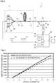
- FIG. 1 is a diagram illustrating a laser device according to the present embodiment.
- the laser device 1 according to the present embodiment is provided with a light source 2, an optical power monitor 30, a driving power source unit 41, a driving current monitor 42, a processor 50, and a memory 56 as a major configuration.
- the light source 2 is provided with a pumping light source unit 20 that emits pumping light, amplification optical fiber 13 doped with an active element that is pumped by the pumping light emitted from the pumping light source unit 20, optical fiber 12 connected to one end of the amplification optical fiber 13, a high-reflectivity FBG 16 provided in the optical fiber 12, a combiner 10 for entering pumping light into the optical fiber 12, optical fiber 14 connected to the other end of the amplification optical fiber 13, and a low-reflectivity FBG 17 provided in the optical fiber 14 as a major configuration.
- the amplification optical fiber 13, the high-reflectivity FBG 16, and the low-reflectivity FBG 17 together form a resonator, and the light source 2 can be understood as including a fiber laser device.
- the pumping light source unit 20 includes a plurality of laser diodes 21, and emits pumping light of a wavelength that pumps the active element used to dope the amplification optical fiber 13.
- Each laser diode 21 of the pumping light source unit 20 is connected to pumping optical fiber 25, and light emitted from each laser diode 21 is propagated through the pumping optical fiber 25 optically connected to each laser diode 21.
- the pumping optical fiber 25 may be multi-mode fiber, for example, and in this case, the pumping light is propagated through the pumping optical fiber 25 as multi-mode light. Note that in the case where the active element used to dope the amplification optical fiber 13 is ytterbium as described later, the wavelength of the pumping light is set to 915 nm, for example.
- the amplification optical fiber 13 includes a core, an inner cladding that gaplessly surrounds the outer circumferential surface of the core, an outer cladding that covers the outer circumferential surface of the inner cladding, and a covering layer that covers the outer circumferential surface of the outer cladding.
- the material used to form the core of the amplification optical fiber 13 may be, for example, quartz doped with an element such as germanium that raises the refractive index and an active element such as ytterbium (Yb) that is pumped by the light emitted from the pumping light source unit 20.
- Yb ytterbium
- Such an active element may be one of the rare-earth elements.
- the rare-earth elements include elements such as thulium (Tm), cerium (Ce), neodymium (Nd), europium (Eu), and erbium (Er). Furthermore, besides the rare-earth elements, an element such as bismuth (Bi) may also be used as the active element.
- the material used to form the inner cladding of the amplification optical fiber 13 may be, for example, pure quartz not doped with any dopant. Note that in the case where the core is not doped with an element that raises the refractive index, the cladding is quartz doped with an element that lowers the refractive index, such as fluorine for example.
- the material used to form the outer cladding of the amplification optical fiber 13 may be a resin having a lower refractive index than the inner cladding, for example, and the material used to form the covering layer of the amplification optical fiber 13 may be a UV-cured resin different from the resin used to form the outer cladding.
- the amplification optical fiber 13 is taken to be a single-mode fiber that propagates light mainly in a basic mode, but to enable the core of the amplification optical fiber to propagate high-power signal light, the diameter of the core may be made similar to the core of multi-mode fiber while still propagating light mainly in a basic mode.
- the amplification optical fiber 13 may be taken to be few-mode fiber that propagates light in a few modes while maintaining the beam quality of the light propagating through the core, or in cases where the beam quality is not a concern, the amplification optical fiber 13 may be taken to be multi-mode fiber.
- the optical fiber 12 has the same configuration as the amplification optical fiber 13, except that the core is not doped with an active element.
- the optical fiber 12 is connected to one end of the amplification optical fiber 13, with the central axis of the core aligned with the central axis of the core of the amplification optical fiber 13. Consequently, the core of the amplification optical fiber 13 and the core of the optical fiber 12 are optically coupled, and the inner cladding of the amplification optical fiber 13 and the inner cladding of the optical fiber 12 are optically coupled.
- the high-reflectivity FBG 16 is provided in the core of the optical fiber 12. With this arrangement, the high-reflectivity FBG 16 is provided on one side of the amplification optical fiber 13. In the high-reflectivity FBG 16, a portion of higher refractive index is repeated on a fixed period along the lengthwise direction of the optical fiber 12. By adjusting the period, the high-reflectivity FBG 16 reflects light of a specific wavelength from among the light emitted by the active element of the amplification optical fiber 13 in the pumped state.
- the high-reflectivity FBG 16 reflects light having a wavelength of 1060 nm for example with a reflectivity of 99% or greater, for example.
- the cores of the pumping optical fibers 25 are connected to the inner cladding of the optical fiber 12.
- the pumping optical fibers 25 connected to the pumping light source unit 20 are optically coupled with the inner cladding of the amplification optical fiber 13 via the inner cladding of the optical fiber 12.
- the optical fiber 14 includes a core similar to the core of the amplification optical fiber 13 except that the core is not doped with an active element, a cladding of similar configuration to the inner cladding of the amplification optical fiber 13 that gaplessly surrounds the outer circumferential surface of the core, and a covering layer that covers the outer circumferential surface of the cladding.
- the optical fiber 14 is connected to the other end of the amplification optical fiber 13, and the core of the amplification optical fiber 13 and the core of the optical fiber 14 are optically coupled.
- the low-reflectivity FBG 17 is provided in the core of the optical fiber 14. With this arrangement, the low-reflectivity FBG 17 is provided on the other side of the amplification optical fiber 13. In the low-reflectivity FBG 17, a portion of higher refractive index is repeated on a fixed period along the lengthwise direction of the optical fiber 14, such that light of at least a portion of the wavelength(s) of the light reflected by the high-reflectivity FBG 16 is reflected at a lower reflectivity than the high-reflectivity FBG 16.
- the low-reflectivity FBG 17 is configured to reflect light of the same wavelength as the light reflected by the high-reflectivity FBG 16, at a reflectivity of 50%.
- the high-reflectivity FBG 16 reflects light having a wavelength of 1060 nm as above
- the low-reflectivity FBG 17 transmits a portion of the light having that wavelength, and the transmitted light is emitted from the optical fiber 14.
- the optical fiber 14 up to at least the portion containing the low-reflectivity FBG 17 is considered part of the light source 2.
- a coupler 15 is provided on the side of the optical fiber 14 opposite from the amplification optical fiber 13.
- optical fiber 18 acting as delivery fiber and optical fiber 19 acting as monitor fiber are connected to the optical fiber 14.
- the optical fiber 14 and the optical fiber 18 may also be a single unitary optical fiber. The majority of the light propagated through the optical fiber 14 is propagated to the optical fiber 18 in the coupler 15, while a fixed ratio of the light propagated through the optical fiber 14 is split at the coupler 15 and directed into the optical fiber 19.
- the optical power monitor 30 is connected to the optical fiber 19.
- the optical power monitor 30 includes a photodetector 31 and an A/D converter 32.
- the photodetector 31 includes a photodiode or the like, and outputs a voltage corresponding to the power of the light emitted from the optical fiber 19.
- the A/D converter 32 is electrically connected to the photodetector 31, and outputs a signal based on the input voltage. Consequently, a signal based on the power of the light propagated through the optical fiber 19 is output from the optical power monitor 30.
- the optical power monitor 30 can be understood as a component that monitors the power of the light emitted from the light source 2. Note that the optical power monitor 30 is not limited to the above configuration insofar as the optical power monitor 30 monitors the power of the light emitted from the light source 2.
- a portion of the light propagated through the optical fiber 14 is split by the coupler 15, and the power of the light is monitored by the optical power monitor 30.
- the power of the light propagated through the optical fiber 14 may also be monitored with a Rayleigh monitor that monitors the Rayleigh light propagated through the optical fiber 14 without using the coupler 15.
- the processor 50 is electrically connected to the optical power monitor 30.
- the driving power source unit 41 is electrically connected to the processor 50.
- the driving power source unit 41 applies a predetermined current to the plurality of laser diodes 21 in the pumping light source unit 20 of the light source 2, on the basis of a signal received from the processor 50.
- the driving current monitor 42 is electrically connected on the electrical path leading from the driving power source unit 41 to the pumping light source unit 20 of the light source 2.
- the driving current monitor 42 monitors the magnitude of the current that the driving power source unit 41 applies to the plurality of laser diodes 21.
- the driving current monitor 42 is electrically connected to the processor 50, and inputs into the processor 50 a signal based on the magnitude of the current that the driving power source unit 41 applies to the plurality of laser diodes 21.
- the processor 50 includes a controller 51, a driving current peak hold unit 52, an optical power peak hold unit 53, a degree-of-deterioration estimation unit 54, and a use-limit time estimation unit 55. Also, the memory 56 is electrically connected to the processor 50.
- the controller 51 controls the driving power source unit 41 and blocks other than the controller 51 inside the processor 50.
- the driving current peak hold unit 52 includes internal memory and a comparator, for example, and holds a maximum value of the current value of the driving current input from the driving current monitor 42. Note that the internal memory may also be substituted by a portion of the memory 56.
- the driving current peak hold unit 52 is reset on a predetermined period, and every time the predetermined period elapses, the held maximum value of the driving current is erased. Consequently, the driving current peak hold unit 52 holds the maximum value within the predetermined period of the driving current applied to the plurality of laser diodes 21.
- the driving current peak hold unit 52 may perform the erasure every predetermined period, or the controller 51 may control the driving current peak hold unit 52 to perform the erasure every predetermined period.
- the predetermined period is not particularly limited, and is set from 1 hour to 24 hours, for example.
- the optical power peak hold unit 53 includes internal memory and a comparator, for example, and holds a maximum value of the optical power input from the optical power monitor 30. Note that the internal memory may also be substituted by a portion of the memory 56. As above, because the optical power monitor 30 can be understood as a component that monitors the power of the light emitted from the light source 2, the optical power peak hold unit 53 that stores the maximum value of the optical power input from the optical power monitor 30 can be understood as holding the maximum value of the power of the light emitted from the light source 2. In the present embodiment, the optical power peak hold unit 53 is reset on the above predetermined period that is reset by the driving current peak hold unit 52, and every time the predetermined period elapses, the held maximum value of the power of the light is erased.
- the optical power peak hold unit 53 holds the maximum value within the predetermined period of the power of the light emitted from the light source 2.
- the optical power peak hold unit 53 may perform the erasure every predetermined period, or the controller 51 may control the optical power peak hold unit 53 to perform the erasure every predetermined period.
- the predetermined period reset by the optical power peak hold unit 53 is taken to be the same as the predetermined period reset by the driving current peak hold unit 52.
- the degree-of-deterioration estimation unit 54 refers to the memory 56 to estimate the degree of deterioration of the light source 2 from the maximum value of the driving current held in the driving current peak hold unit 52 and the maximum value of the power of the light held in the optical power peak hold unit 53.
- FIG. 2 is a graph that schematically illustrates a relationship, stored in the memory 56, between the magnitude of the driving current, the magnitude of the power of the light, and the degree of deterioration of the light source 2.
- the horizontal axis represents the magnitude of the driving current applied to the plurality of laser diodes 21 of the pumping light source unit 20, while the vertical axis represents the power of the light emitted from the light source 2.
- FIG. 2 the horizontal axis represents the magnitude of the driving current applied to the plurality of laser diodes 21 of the pumping light source unit 20, while the vertical axis represents the power of the light emitted from the light source 2.
- the solid line indicates the magnitude of the driving current and the magnitude of the power of the light in a state in which the efficiency of the plurality of laser diodes 21 of the pumping light source unit 20 is not reduced
- the dashed line indicates the magnitude of the driving current and the magnitude of the power of the light in a state in which the plurality of laser diodes 21 of the pumping light source unit 20 have a 10% degree of deterioration.
- the degree of deterioration indicates the ratio of the drop in the power of the light emitted from the light source 2 in the case where the driving current that should be applied to the plurality of laser diodes 21 in the state in which each laser diode 21 is not deteriorated is applied to the plurality of laser diodes 21 in a deteriorated light source 2. Consequently, the degree of deterioration exists in a predetermined relationship with the reduction in the efficiency of the light source 2.
- the degree of deterioration of the light source 2 is 10%.
- the degree of deterioration is equal to the ratio of malfunctioning laser diodes 21 among the plurality of laser diodes 21, or in other words the malfunction ratio.
- the degree of deterioration of the light source 2 is 10%.
- the driving current to be applied to the plurality of laser diodes 21 of the pumping light source unit 20 is greater when the light source 2 is in a deteriorated state compared to when the light source 2 is in a non-deteriorated state. Note that in FIG.
- the memory 56 may store the relationship between the magnitude of the driving current and the magnitude of the power of the light for the cases of 0%, 5%, 10%, 15%, 20%, and 25% degree of deterioration of the light source 2, for example.
- the degree-of-deterioration estimation unit 54 reads out the maximum value of the driving current held in the driving current peak hold unit 52 and the maximum value of the power of the light held in the optical power peak hold unit 53. Subsequently, a degree of deterioration stored in the memory 56 that is close to the relationship between the read-out maximum values of the driving current and the power of the light is determined. For example, in the case where the power of the light emitted from the light source 2 is 5 kW and the driving current is 9.5 A, from FIG. 2 the degree-of-deterioration estimation unit 54 estimates that all of the laser diodes 21 are operating without deterioration, and outputs a result indicating the same.
- the degree-of-deterioration estimation unit 54 estimates that the light source 2 has a 10% degree of deterioration, and outputs a result indicating the same.
- the use-limit time estimation unit 55 refers to the memory 56 to estimate the time until the light source 2 reaches a predetermined use limit from the degree of deterioration of the light source 2 estimated by the degree-of-deterioration estimation unit 54.
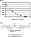
- FIG. 3 is a graph that schematically illustrates a relationship, stored in the memory 56, between the degree of deterioration and the time until the light source reaches a predetermined use limit.
- the horizontal axis represents the degree of deterioration of the light source 2
- the vertical axis represents the magnitude of the light emitted from the light source 2.
- the light source 2 reaches the use limit after 120,000 hours in the case where all of the laser diodes 21 operate without deteriorating, but in the case where the degree of deterioration of the light source 2 is 10%, the use limit is reached after 40,000 hours, and in the case where the degree of deterioration of the light source 2 is 15%, the use limit is reached after 20,000 hours. Furthermore, in the case where the degree of deterioration of the light source 2 is 25%, the light source 2 has reached the use limit.
- the use-limit time estimation unit 55 reads the signal related to the degree of deterioration of the light source 2 output by the degree-of-deterioration estimation unit 54, and if the estimation result from the degree-of-deterioration estimation unit 54 indicates that the degree of deterioration of the light source 2 is 10%, the use-limit time estimation unit 55 estimates that the time until the use limit of the light source 2 is 40,000 hours, whereas if the estimation result from the degree-of-deterioration estimation unit 54 indicates that the degree of deterioration of the light source 2 is 25% or higher, the use-limit time estimation unit 55 outputs a result indicating that the light source 2 has reached the use limit.
- the degree of deterioration of the light source 2 estimated by the degree-of-deterioration estimation unit 54 and the time until the use limit of the light source 2 estimated by the use-limit time estimation unit 55 are preferably output to an output unit such as a monitor for visualization.
- the controller 51 controls the driving power source unit 41 such that the driving power source unit 41 applies a predetermined driving current to each laser diode 21 of the pumping light source unit 20. Subsequently, pumping light is emitted from each laser diode 21.
- the pumping light emitted from the pumping light source unit 20 proceeds from the pumping optical fiber 25 through the inner cladding of the optical fiber 12 and enters the inner cladding of the amplification optical fiber 13.
- the pumping light entering the inner cladding of the amplification optical fiber 13 mainly propagates through the inner cladding, and when passing through the core of the amplification optical fiber 13, pumps the active element used to dope the core.
- the pumped active element emits light of a specific wavelength by spontaneous emission.
- This spontaneously emitted light propagates through the core of the amplification optical fiber 13, and the light of a portion of the wavelength(s) is reflected by the high-reflectivity FBG 16.
- the low-reflectivity FBG 17 reflects light of the wavelength that the low-reflectivity FBG 17 reflects is reflected by the low-reflectivity FBG 17 and travels back-and-forth between the high-reflectivity FBG 16 and the low-reflectivity FBG 17, or in other words inside the resonator.
- This light is amplified by stimulated emission when propagating through the core of the amplification optical fiber 13, and enters a laser oscillation state. Additionally, a portion of the amplified light is transmitted through the low-reflectivity FBG 17 and emitted from the optical fiber 14. Almost all of the light emitted from the optical fiber 14 is propagated to the optical fiber 18 in the coupler 15, and is emitted from the optical fiber 18. With this arrangement, light is emitted from the laser device 1.
- FIG. 4 is a flowchart illustrating a method for estimating the degree of deterioration of the light source 2 and a method for estimating the use-limit time of the light source 2.
- the driving current monitor 42 detects the driving current and inputs a signal corresponding to the magnitude of the driving current into the processor 50.
- the controller 51 controls the driving current peak hold unit 52 in a driving current peak holding step ST1.
- the driving current peak hold unit 52 controlled by the controller 51 compares the maximum value of the driving current already held within the predetermined period by the driving current peak hold unit 52 to the magnitude of the driving current input from the driving current monitor 42.
- the driving current peak hold unit 52 newly holds the magnitude of the driving current input from the driving current monitor 42 as the maximum value of the driving current.
- the driving current peak hold unit 52 keeps holding the currently held maximum value of the driving current.
- the driving current monitor 42 preferably includes a low-pass filter and is configured not to detect peaks in the driving current with a duration of 10 ⁇ s or less, for example.
- the driving current peak hold unit 52 may be controlled to treat such values as spike noise and not handle such values as a maximum value of the driving current.
- the photodetector 31 when light is emitted from the light source 2 as above, most of the light propagated through the optical fiber 14 is propagated to the delivery fiber, namely the optical fiber 18, in the coupler 15, but a fixed ratio of the light propagated through the optical fiber 14 is propagated to the optical fiber 19.
- the light propagated to the optical fiber 19 is received by the photodetector 31.
- the photodetector 31 outputs a voltage based on the power of the received light, and the voltage is input into the A/D converter 32.
- the A/D converter 32 outputs a signal based on the input voltage, and the signal is input into the processor 50. Consequently, a signal based on the power of the light propagated through the optical fiber 19 is output from the optical power monitor 30 that includes the A/D converter 32 as above.
- the signal is also a signal based on the power of the light propagated through the optical fiber 14.
- the controller 51 controls the optical power peak hold unit 53 in an optical power peak holding step ST2.
- the optical power peak hold unit 53 controlled by the controller 51 compares the maximum value of the optical power already held within the predetermined period by the optical power peak hold unit 53 to the magnitude of the optical power input from the optical power monitor 30.
- the optical power peak hold unit 53 newly holds the magnitude of the optical power input from the optical power monitor 30 as the maximum value of the optical power.
- the optical power peak hold unit 53 keeps holding the currently held maximum value of the optical power.
- the optical power monitor 30 preferably includes a low-pass filter and is configured not to detect peaks in the light with a duration of 10 ⁇ s or less, for example.
- the optical power peak hold unit 53 may be controlled to treat such values as unintentional light and not handle such values as a maximum value of the optical power.
- the controller 51 controls the degree-of-deterioration estimation unit 54.
- the degree-of-deterioration estimation unit 54 controlled by the controller 51 refers to the memory 56 to estimate the degree of deterioration of the light source 2 as above from the maximum value of the driving current within the predetermined period held in the driving current peak hold unit 52 and the maximum value of the power of the light within the predetermined period held in the optical power peak hold unit 53. Note that in the case where an output unit is provided as above, the estimated degree of deterioration of the light source 2 is output from the output unit.
- the controller 51 controls the use-limit time estimation unit 55.
- the use-limit time estimation unit 55 controlled by the controller 51 refers to the memory 56 to estimate the time until the light source 2 reaches a predetermined use limit from the degree of deterioration of the light source 2 estimated by the degree-of-deterioration estimation unit 54 as above. Note that in the case where an output unit is provided as above, the estimated time until the use limit of the light source 2 is output from the output unit.
- the degree of deterioration of the light source 2 and the time until the use limit of the light source 2 are estimated.
- the degree of deterioration of the light source 2 and the time until the light source 2 reaches the use limit estimated in this way are not updated within the predetermined period unless the maximum value of the driving current held by the driving current peak hold unit 52 or the maximum value of the power of the light held by the optical power peak hold unit 53 is updated. Also, because the driving current peak hold unit 52 and the optical power peak hold unit 53 are reset every predetermined period as above, after a reset, the maximum value of the driving current is again held in the driving current peak hold unit 52, while in addition, the maximum value of the power of the light is again held in the optical power peak hold unit 53. Consequently, after a reset, the degree of deterioration of the light source 2 and the time until the light source 2 reaches the use limit are estimated.
- the controller 51 controls the driving power source unit 41 to increase the driving current in a range in which the power of the light emitted from the light source 2 does not exceed the power of the light before the signal indicating the drop in the power of the light was input from the optical power monitor 30.
- FIG. 5 is a diagram that schematically illustrates a relationship between the magnitude of the driving current, the magnitude of the power of the light, and the degree of deterioration of the light source 2 in a case where the controller 51 controls the driving power source unit 41 to increase the driving current in a case where the light source 2 has deteriorated.
- FIG. 5 illustrates an example of a case where the light source 2 has deteriorated 10% from a non-deteriorated state.
- the driving power source unit 41 increases the value of the current as indicated by the dashed arrow in FIG. 5 .
- the power of the light emitted from the light source 2 increases compared to the case where the driving current is not increased at all as indicated by the dotted arrow in FIG. 5 .
- the power of the light emitted from the light source 2 is smaller compared to the state before the light source 2 became deteriorated, that is, before the signal indicating a drop in the power of the light was input into the processor from the optical power monitor 30. Consequently, the maximum value of the driving current held in the driving current peak hold unit 52 is updated, but the maximum value of the power of the light held in the optical power peak hold unit 53 remains the same as before the signal indicating a drop in the power of the light was input from the optical power monitor 30.
- the degree-of-deterioration estimation unit 54 can appropriately estimate the degree of deterioration of the light source 2 in the degree-of-deterioration estimating step ST3, and the use-limit time estimation unit 55 can accurately estimate the time until the light source 2 reaches the use limit in the use-limit time estimating step ST4.
- the driving power source unit 41 is preferably controlled such that the power of the light emitted from the light source 2 becomes the same as the power of the light before the signal indicating a drop in the power of the light was input from the optical power monitor 30.
- the controller 51 performs a feedback control causing the state of reduced power of the light emitted from the light source 2 to be temporary.
- the driving power source unit 41 increases the value of the current as indicated by the solid arrow in FIG. 5 .
- the maximum value of the power of the light held in the optical power peak hold unit 53 does not change, but the maximum value of the driving current held in the driving current peak hold unit 52 is updated. Consequently, in the degree-of-deterioration estimating step ST3, the degree-of-deterioration estimation unit 54 can estimate the degree of deterioration of the light source 2 more appropriately. For this reason, in the use-limit time estimating step ST4, the use-limit time estimation unit 55 can estimate the time until the light source 2 reaches the use limit more accurately.
- the laser device 1 includes a light source 2 including a plurality of laser diodes 21; a driving current peak hold unit 52 that holds a maximum value within a predetermined period of a driving current applied to the plurality of laser diodes 21; an optical power peak hold unit 53 that holds a maximum value within the predetermined period of a power of light emitted from the light source 2; memory 56 that stores a relationship between a magnitude of the driving current, a magnitude of the power of the light, and a degree of deterioration of the light source 2; and a degree-of-deterioration estimation unit 54 that refers to the memory 56 to estimate the degree of deterioration from the maximum value within the predetermined period of the driving current held in the driving current peak hold unit 52 and the maximum value within the predetermined period of the power of the light held in the optical power peak hold unit 53.
- a method for estimating the degree of deterioration of the light source 2 of the laser device 1 includes a driving current peak holding step ST1 that holds a maximum value within a predetermined period of a driving current applied to the plurality of laser diodes 21; an optical power peak holding step ST2 that holds a maximum value within the predetermined period of a power of light emitted from the light source 2; and a degree-of-deterioration estimating step ST3 that refers to the memory 56 that stores a relationship between a magnitude of the driving current, a magnitude of the power of the light, and a degree of deterioration of the light source 2 to estimate the degree of deterioration from the maximum value within the predetermined period of the driving current held in the driving current peak holding step ST1 and the maximum value within the predetermined period of the power of the light held in the optical power peak holding step ST2.
- the state of deterioration of the light source can be estimated appropriately by estimating the degree of deterioration of the light source from the maximum value of the driving current and the maximum value of the power of the light within a predetermined period.
- the memory 56 additionally stores the relationship between the degree of deterioration and the time until the light source 2 reaches a predetermined use limit
- the laser device 1 is additionally provided with the use-limit time estimation unit 55 that refers to the memory 56 to additionally estimate the time until the use limit from the estimated degree of deterioration.
- the method for estimating the degree of deterioration of the light source 2 of the laser device 1 according to the present embodiment additionally includes a use-limit time estimating step ST4 that additionally estimates the time until the light source 2 reaches a predetermined use limit from the estimated degree of deterioration.
- FIG. 6 is a diagram illustrating a laser device 1 according to the present embodiment. As illustrated in FIG. 6 , in the laser device 1 according to the present embodiment, the amplification optical fiber 13 is disposed on the outside of the light source 2, and the light source 2 has a configuration similar to the pumping light source unit 20 of the first embodiment.
- the laser diodes 21 of the light source 2 are respectively connected to the pumping optical fiber 25, similarly to the pumping light source unit 20 of the first embodiment.
- each pumping optical fiber 25 is connected in the combiner 10 to the optical fiber 12 in which the high-reflectivity FBG 16 is formed.
- the end of the optical fiber 12 on the opposite side from the combiner 10 is connected to the amplification optical fiber 13.
- the end of the amplification optical fiber 13 on the opposite side from the optical fiber 12 is connected to the optical fiber 14 in which the low-reflectivity FBG 17 is formed.
- the side of the optical fiber 14 opposite from the amplification optical fiber 13 is connected to the delivery fiber, that is, the optical fiber 18.
- the coupler 15 is provided on the optical fiber 12 between the combiner 10 and the high-reflectivity FBG 16. The majority of the light propagated through the optical fiber 12 continues to be propagated through the optical fiber 12 in the coupler 15, while a fixed ratio of the light propagated through the optical fiber 12 is split at the coupler 15 and directed into the optical fiber 19.
- the laser device 1 forms a fiber laser device including the light source 2 and the amplification optical fiber 13.
- the power of the light emitted from the amplification optical fiber 13 is monitored by the optical power monitor 30, whereas in the laser device 1 according to the present embodiment, the optical power monitor 30 monitors the power of the light before the light enters the amplification optical fiber 13, and the optical power peak hold unit 53 holds the maximum value within the predetermined period of the power of the light before the light enters the amplification optical fiber 13.
- the relationship between the magnitude of the driving current, the magnitude of the power of the light, and the degree of deterioration of the light source 2 stored in the memory 56 referenced by the degree-of-deterioration estimation unit 54 is different from the relationship between the magnitude of the driving current, the magnitude of the power of the light, and the degree of deterioration of the light source 2 stored in the memory 56 in the first embodiment.
- the power of the light propagated through the optical fiber 12 may also be monitored with a Rayleigh monitor that monitors the Rayleigh light propagated through the optical fiber 12 without using the coupler 15.
- the degree of deterioration of the light source 2 and the time until the light source 2 reaches the use limit may be estimated in a similar manner as the method for estimating the degree of deterioration of the light source 2 and the method for estimating the use-limit time of the light source 2 in the laser device 1 according to the first embodiment.
- the degree of deterioration and the use-limit time of the light source 2 acting as a pumping light source unit can be estimated.
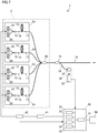
- FIG. 7 is a diagram illustrating the laser device 1 according to the present embodiment.
- the light source 2 is provided with a plurality of laser units 2a.
- Each laser unit 2a has a configuration similar to the light source 2 according to the first embodiment.
- the light source 2 in the laser device 1 according to the present embodiment is configured to include a plurality of the light source 2 according to the first embodiment.
- the pumping light source unit 20 it is sufficient for the pumping light source unit 20 to include one or more laser diodes 21.
- Each optical fiber 14 that emits the light from each light source 2 is connected to the delivery fiber, namely the optical fiber 18, in a combiner 60.
- the coupler 15 is provided in the middle of the optical fiber 18. Therefore, the majority of the light propagated through the optical fiber 18 continues to be propagated through the optical fiber 18 in the coupler 15, while a fixed ratio of the light propagated through the optical fiber 18 is split at the coupler 15 and directed into the optical fiber 19.
- each laser unit 2a has a configuration similar to the light source 2 according to the first embodiment
- the laser device 1 according to the first embodiment can be understood as monitoring the power of the light emitted from a single laser unit with the optical power monitor 30, whereas in the laser device 1 according to the present embodiment, the power of the light emitted from a plurality of laser units 2a is monitored with the optical power monitor 30.
- the laser device 1 according to the first embodiment and the laser device 1 according to the present embodiment are similar in that the power of the light emitted from the light source 2 including the plurality of laser diodes 21 is monitored with the optical power monitor 30.
- the power of the light propagated through the optical fiber 18 may also be monitored with a Rayleigh monitor that monitors the Rayleigh light propagated through the optical fiber 18 without using the coupler 15.
- the optical power peak hold unit 53 holds the maximum value within the predetermined period of the power of the light emitted from the plurality of laser units 2a. For this reason, the relationship between the magnitude of the driving current, the magnitude of the power of the light, and the degree of deterioration of the light source 2 stored in the memory 56 referenced by the degree-of-deterioration estimation unit 54 is different from the relationship between the magnitude of the driving current, the magnitude of the power of the light, and the degree of deterioration of the light source 2 stored in the memory 56 in the first embodiment.
- the degree of deterioration of the light source 2 and the time until the light source 2 reaches the predetermined use limit may be estimated in a similar manner as the method for estimating the degree of deterioration of the light source 2 and the method for estimating the use-limit time of the light source 2 in the laser device 1 according to the first embodiment.
- the amplification optical fiber 13, the high-reflectivity FBG 16, and the low-reflectivity FBG 17 are not strictly necessary.
- the laser device 1 according to the first embodiment and the laser device according to the second embodiment have substantially the same configuration.
- each laser unit 2a according to the third embodiment may have a configuration similar to the light source 2 according to the second embodiment.
- the high-reflectivity FBG 16 and the low-reflectivity FBG 17 are not strictly necessary.
- the light source 2 according to the first embodiment, the laser device 1 according to the second embodiment, or each laser unit 2a according to the third embodiment may also be configured as a master oscillator - power amplifier (MO-PA) fiber laser device including a different type of light source unit than a pumping light source unit.
- MO-PA master oscillator - power amplifier
- the laser device 1 includes the driving current monitor 42, and the driving current peak hold unit 52 holds the maximum value of the current value of the driving current input from the driving current monitor 42 according to a signal from the driving current monitor 42.
- the driving current monitor 42 is not strictly necessary, and the driving current peak hold unit 52 may also hold the maximum value of the driving current on the basis of a signal by which the controller 51 controls the driving power source unit 41, for example.
- a laser device capable of appropriately estimating a state of deterioration of a light source using laser diodes and a method for estimating the degree of deterioration of a light source of a laser device are provided.
- the present invention is usable in a variety of industries such as the laser processing field and the medical field.
Landscapes
- Physics & Mathematics (AREA)
- Electromagnetism (AREA)
- Optics & Photonics (AREA)
- Engineering & Computer Science (AREA)
- Condensed Matter Physics & Semiconductors (AREA)
- General Physics & Mathematics (AREA)
- Plasma & Fusion (AREA)
- Microelectronics & Electronic Packaging (AREA)
- Lasers (AREA)
- Semiconductor Lasers (AREA)
Abstract
Description
- The present invention relates to a laser device capable of appropriately detecting a state of deterioration of a light source using laser diodes and a method for estimating the degree of deterioration of a light source of a laser device.
- Because fiber laser devices can obtain light with excellent light-condensing properties, high power density, and a small beam spot, fiber laser devices are being used in a variety of fields such as the laser processing field and the medical field. Consequently, fiber laser devices are sometimes used in combination with a processing machine.
- In a fiber laser device, a plurality of laser diodes (LDs) are typically used as a source of pumping light. In some cases, laser diodes may malfunction or exhibit weakened output for various reasons. If one or some of the laser diodes in a fiber laser device malfunction or exhibit reduced output, the pumping light source may still continue to be used in some cases through means such as increasing the power of the light emitted from the other laser diodes. However, in some cases the power of the light from the pumping light source falls by a certain ratio or greater, in other cases the pumping light source must be replaced, and in still other cases the fiber laser device itself reaches a use limit and must be replaced. Consequently, there is demand for a way to estimate the degree of deterioration of a pumping light source.
- Patent Literature 1 below describes an optical amplifier capable of determining the degree of deterioration of a pumping light source. In the optical amplifier, the relationship between the driving current of a pumping light source element, such as a laser diode, and the power of the emitted pumping light in an initial state is compared to the relationship between the driving current of the pumping light source element and the power of the emitted pumping light in a state after a certain duration of use. From the comparison result, the degree of deterioration of the pumping light source element is determined.
- [Patent Literature 1] Japanese Patent No.
4532249 - In Patent Literature 1, the relationship between the driving current of a pumping light source element, such as a laser diode, and the power of the emitted pumping light is used to determine the degree of deterioration of each pumping light source element. However, the timing when the driving current applied to a laser diode and the timing when light is emitted from the laser diode may not match each other in some cases. Consequently, at the timing when a large driving current is applied to a laser diode, it is not necessarily always the case that high-power light will be emitted from the pumping light source, and sometimes high-power light may be emitted from the pumping light source at a timing when a small driving current is applied to the laser diode, or low-power light may be emitted from the pumping light source at a timing when a large driving current is applied to the laser diode. Consequently, simply comparing the relationship between the magnitude of the driving current input into a laser diode to the power of light emitted from the pumping light source may result in a determination that the pumping light source is deteriorated or that the pumping light source is not deteriorated much, depending on the timing when the degree of deterioration is determined. In this way, the estimation of the degree of deterioration of the pumping light source becomes inconsistent, and there are concerns about being unable to appropriately estimate the degree of deterioration. Such concerns may also extend to laser devices other than fiber lasers, insofar as the laser device uses a laser diode.
- Accordingly, an object of the present invention is to provide a laser device capable of appropriately estimating a state of deterioration of a light source using laser diodes and a method for estimating the degree of deterioration of a light source of a laser device.
- To solve the issues described above, the present invention provides a laser device including: a light source including a plurality of laser diodes; a driving current peak hold unit that holds a maximum value within a predetermined period of a driving current applied to the plurality of laser diodes; an optical power peak hold unit that holds a maximum value within the predetermined period of a power of light emitted from the light source; memory that stores a relationship between a magnitude of the driving current, a magnitude of the power of the light, and a degree of deterioration of the light source; and a degree-of-deterioration estimation unit that refers to the memory to estimate the degree of deterioration from the maximum value within the predetermined period of the driving current held in the driving current peak hold unit and the maximum value within the predetermined period of the power of the light held in the optical power peak hold unit.
- As described above, the timing when the driving current applied to a laser diode and the timing when light is emitted from the laser diode may not match each other in some cases. Consequently, in some cases, the timing when the magnitude of the driving current applied to a laser diode reaches a maximum may not match the timing when the power of the light emitted from a light source including a plurality of laser diodes reaches a maximum. In other words, in some cases, the maximum driving current is applied to a laser diode, and after predetermined amount of time elapses, light of maximum power according to the maximum driving current is emitted. For this reason, even in cases where the timing when the magnitude of the driving current reaches a maximum does not match the timing when the power of the light reaches a maximum, the maximum value of the magnitude of the driving current and the maximum value of the power of the light emitted from the light source correspond with each other for the most part. Consequently, by estimating the degree of deterioration of the light source from the maximum value of the driving current and the maximum value of the power of the light within a predetermined period like in the present invention, the state of deterioration of the light source can be estimated appropriately. Note that the maximum value of the driving current and the maximum value of the power of the light do not include phenomena such as a large current that flows momentarily because of spike noise or the like, or light having a high peak value that is emitted momentarily because of unintentional oscillations or the like.
- Further, the memory additionally stores a relationship between the degree of deterioration and a time until the light source reaches a predetermined use limit, the laser device preferably further includes: a use-limit time estimation unit that refers to the memory to additionally estimate the time until the light source reaches the use limit from the estimated degree of deterioration.
- Even when the state of deterioration of the light source is estimated appropriately, it is still difficult for a user to grasp the amount of time left until the use limit of the laser device is reached on the basis of the estimated degree of deterioration. However, as above, by estimating the time until a predetermined use limit is reached from the degree of deterioration of the light source, the user of the laser device can easily grasp the amount of time left until the light source reaches the use limit, and make appropriate preparations, such as readying a spare light source, in a timely manner.
- Further, the laser device preferably further includes: a controller; a driving power source unit that applies a current to the plurality of laser diodes; and an optical power monitor that monitors the power of the light emitted from the light source, in which in a case where a signal indicating a drop in the power of the light is input from the optical power monitor, the controller controls the driving power source unit to increase the driving current in a range in which the power of the light emitted from the light source does not exceed the power of the light before the signal indicating the drop in the power of the light was input from the optical power monitor.
- In this case, even if several of the plurality of laser diodes in the light source become deteriorated and the power of the light emitted from the light source drops, by controlling the driving power source unit to increase the driving current, an insufficiency in the power of the light emitted from the laser device can be suppressed. Also, by increasing the driving current, the maximum value of the driving current held in the driving current peak hold unit is updated. On the other hand, the maximum value of the power of the light held in the optical power peak hold unit remains the same value from before the signal indicating a drop in the power of the light was input from the optical power monitor. In the case where the light source has deteriorated, the driving current increases even if the power of the emitted light is constant. Consequently, according to the laser device, the state of deterioration of the light source can be estimated more appropriately.
- Further, the laser device preferably further includes: a controller; a driving power source unit that applies a current to the plurality of laser diodes; and an optical power monitor that monitors the power of the light emitted from the light source, in which in a case where a signal indicating a drop in the power of the light is input from the optical power monitor, the controller controls the driving power source unit to make the power of the light emitted from the light source equal to the power of the light before the signal indicating the drop in the power of the light was input from the optical power monitor.
- Through such control, an insufficiency in the power of the light emitted from the laser device can be suppressed further. Also, by increasing the driving current such that the power of the emitted light becomes the same as the power before the signal indicating a drop in the power of the light was input, the maximum value of the driving current held in the driving current peak hold unit is updated. Consequently, the state of deterioration of the light source can be estimated appropriately.
- Further, the driving current peak hold unit preferably erases the maximum value of the driving current stored within the predetermined period after the predetermined period elapses, and the optical power peak hold unit erases the maximum value of the power of the light stored within the predetermined period after the predetermined period elapses.
- By erasing the maximum value of the driving current and the maximum value of the power of the light after a predetermined period elapses in this way, the capacity of the temporary storage unit inside the driving current peak hold unit and the optical power peak hold unit can be reduced. Also, even in cases where the user switches to low-output operation for long-term use, a memory-full state can be suppressed and the present degree of laser diode deterioration can be diagnosed.
- Further, it is preferable that the light source additionally include amplification optical fiber doped with an active element that is pumped by light emitted from the plurality of laser diodes.
- In this case, the light source is formed from a fiber laser device, and the plurality of laser diodes acts as the pumping light source unit that emits pumping light. With such a light source, the light emitted from the plurality of laser diodes pumps the active element, and light emitted from the pumped active element is emitted from the amplification optical fiber. In this case, compared to the case where the light emitted from the laser diodes is emitted directly from the light source, the timing when the current is applied to the laser diodes and the timing when the light is emitted from the light source tend to separate further. However, according to the laser device according to the present invention in which the degree of deterioration of the light source is estimated from the maximum value of the driving current and the maximum value of the power of the light, even in cases that include amplification optical fiber as above, the state of deterioration of the light source can be estimated appropriately.
- Further, the laser device may further include amplification optical fiber doped with an active element that is pumped by light emitted from the light source, in which the driving current peak hold unit holds the maximum value of the power of the light before the light enters the amplification optical fiber.
- In this case, because the light emitted from the light source pumps the active element of the amplification optical fiber, the light source can be understood to be a pumping light source, and a fiber laser device is formed as the overall laser device. Even in such a case, the state of deterioration of the light source can be estimated appropriately. Also, in this case, by combining the above with another monitor, it becomes possible to better estimate the malfunctioning location in the overall fiber laser.
- Further, to solve the issue described above, the present invention provides a method for estimating a degree of deterioration of a light source of a laser device, in which the light source includes a plurality of laser diodes, the method including: a driving current peak holding step of holding a maximum value within a predetermined period of a driving current applied to the plurality of laser diodes; an optical power peak holding step of holding a maximum value within the predetermined period of a power of light emitted from the light source; and a degree-of-deterioration estimating step of referring to a memory that stores a relationship between a magnitude of the driving current, a magnitude of the power of the light, and the degree of deterioration of the light source, and estimating the degree of deterioration from the maximum value within the predetermined period of the driving current held in the driving current peak holding step and the maximum value within the predetermined period of the power of the light held in the optical power peak holding step.
- According to such a method for estimating the degree of deterioration of a light source of a laser device, by estimating the degree of deterioration of the light source from the maximum value of the driving current and the maximum value of the power of the light within a predetermined period, the state of deterioration of the light source can be estimated appropriately.
- Preferably, the memory additionally stores a relationship between the degree of deterioration and the amount of time until the light source reaches a predetermined use limit, and the method for estimating the degree of deterioration of a light source of a laser device additionally includes a use-limit time estimating step that additionally estimates the amount of time until the light source reaches the use limit from the estimated degree of deterioration.
- According to such a method for estimating the degree of deterioration of a light source of a laser device, a user of the laser device can easily grasp the amount of time left until the light source reaches the use limit, and make appropriate preparations, such as readying a spare light source, in a timely manner.
- As described above, according to the present invention, a laser device capable of appropriately estimating a state of deterioration of a light source using laser diodes and a method for estimating the degree of deterioration of a light source of a laser device are provided.
-
-
FIG. 1 is a diagram illustrating a laser device according to a first embodiment of the present invention. -
FIG. 2 is a graph that schematically illustrates a relationship, stored in memory, between the magnitude of the driving current, the magnitude of the power of the light, and the degree of deterioration of the light source. -
FIG. 3 is a graph that schematically illustrates a relationship, stored in memory, between the degree of deterioration and the time until the light source reaches a predetermined use limit. -
FIG. 4 is a flowchart illustrating operations by a processor. -
FIG. 5 is a diagram that schematically illustrates a relationship between the magnitude of the driving current, the magnitude of the power of the light, and the degree of deterioration of the light source in a case where a controller controls a driving power source unit to increase the driving current in a case where the light source has deteriorated. -
FIG. 6 is a diagram illustrating a laser device according to a second embodiment of the present invention. -
FIG. 7 is a diagram illustrating a laser device according to a third embodiment of the present invention. - Hereinafter, preferred embodiments of the laser device and the method for estimating the degree of deterioration of a light source of a laser device according to the present invention will be described in detail with reference to the drawings.
-
FIG. 1 is a diagram illustrating a laser device according to the present embodiment. As illustrated inFIG. 1 , the laser device 1 according to the present embodiment is provided with alight source 2, anoptical power monitor 30, a drivingpower source unit 41, a drivingcurrent monitor 42, aprocessor 50, and amemory 56 as a major configuration. - The
light source 2 is provided with a pumpinglight source unit 20 that emits pumping light, amplificationoptical fiber 13 doped with an active element that is pumped by the pumping light emitted from the pumpinglight source unit 20,optical fiber 12 connected to one end of the amplificationoptical fiber 13, a high-reflectivity FBG 16 provided in theoptical fiber 12, acombiner 10 for entering pumping light into theoptical fiber 12,optical fiber 14 connected to the other end of the amplificationoptical fiber 13, and a low-reflectivity FBG 17 provided in theoptical fiber 14 as a major configuration. The amplificationoptical fiber 13, the high-reflectivity FBG 16, and the low-reflectivity FBG 17 together form a resonator, and thelight source 2 can be understood as including a fiber laser device. - The pumping
light source unit 20 includes a plurality oflaser diodes 21, and emits pumping light of a wavelength that pumps the active element used to dope the amplificationoptical fiber 13. Eachlaser diode 21 of the pumpinglight source unit 20 is connected to pumpingoptical fiber 25, and light emitted from eachlaser diode 21 is propagated through the pumpingoptical fiber 25 optically connected to eachlaser diode 21. The pumpingoptical fiber 25 may be multi-mode fiber, for example, and in this case, the pumping light is propagated through the pumpingoptical fiber 25 as multi-mode light. Note that in the case where the active element used to dope the amplificationoptical fiber 13 is ytterbium as described later, the wavelength of the pumping light is set to 915 nm, for example. - The amplification
optical fiber 13 includes a core, an inner cladding that gaplessly surrounds the outer circumferential surface of the core, an outer cladding that covers the outer circumferential surface of the inner cladding, and a covering layer that covers the outer circumferential surface of the outer cladding. The material used to form the core of the amplificationoptical fiber 13 may be, for example, quartz doped with an element such as germanium that raises the refractive index and an active element such as ytterbium (Yb) that is pumped by the light emitted from the pumpinglight source unit 20. Such an active element may be one of the rare-earth elements. Besides ytterbium mentioned above, the rare-earth elements include elements such as thulium (Tm), cerium (Ce), neodymium (Nd), europium (Eu), and erbium (Er). Furthermore, besides the rare-earth elements, an element such as bismuth (Bi) may also be used as the active element. Also, the material used to form the inner cladding of the amplificationoptical fiber 13 may be, for example, pure quartz not doped with any dopant. Note that in the case where the core is not doped with an element that raises the refractive index, the cladding is quartz doped with an element that lowers the refractive index, such as fluorine for example. Also, the material used to form the outer cladding of the amplificationoptical fiber 13 may be a resin having a lower refractive index than the inner cladding, for example, and the material used to form the covering layer of the amplificationoptical fiber 13 may be a UV-cured resin different from the resin used to form the outer cladding. The amplificationoptical fiber 13 is taken to be a single-mode fiber that propagates light mainly in a basic mode, but to enable the core of the amplification optical fiber to propagate high-power signal light, the diameter of the core may be made similar to the core of multi-mode fiber while still propagating light mainly in a basic mode. Alternatively, the amplificationoptical fiber 13 may be taken to be few-mode fiber that propagates light in a few modes while maintaining the beam quality of the light propagating through the core, or in cases where the beam quality is not a concern, the amplificationoptical fiber 13 may be taken to be multi-mode fiber. - The
optical fiber 12 has the same configuration as the amplificationoptical fiber 13, except that the core is not doped with an active element. Theoptical fiber 12 is connected to one end of the amplificationoptical fiber 13, with the central axis of the core aligned with the central axis of the core of the amplificationoptical fiber 13. Consequently, the core of the amplificationoptical fiber 13 and the core of theoptical fiber 12 are optically coupled, and the inner cladding of the amplificationoptical fiber 13 and the inner cladding of theoptical fiber 12 are optically coupled. - Also, the high-
reflectivity FBG 16 is provided in the core of theoptical fiber 12. With this arrangement, the high-reflectivity FBG 16 is provided on one side of the amplificationoptical fiber 13. In the high-reflectivity FBG 16, a portion of higher refractive index is repeated on a fixed period along the lengthwise direction of theoptical fiber 12. By adjusting the period, the high-reflectivity FBG 16 reflects light of a specific wavelength from among the light emitted by the active element of the amplificationoptical fiber 13 in the pumped state. In the case where the active element used to dope the amplificationoptical fiber 13 is ytterbium as described above, the high-reflectivity FBG 16 reflects light having a wavelength of 1060 nm for example with a reflectivity of 99% or greater, for example. - Also, in the
combiner 10, the cores of the pumpingoptical fibers 25 are connected to the inner cladding of theoptical fiber 12. With this arrangement, the pumpingoptical fibers 25 connected to the pumpinglight source unit 20 are optically coupled with the inner cladding of the amplificationoptical fiber 13 via the inner cladding of theoptical fiber 12. - The
optical fiber 14 includes a core similar to the core of the amplificationoptical fiber 13 except that the core is not doped with an active element, a cladding of similar configuration to the inner cladding of the amplificationoptical fiber 13 that gaplessly surrounds the outer circumferential surface of the core, and a covering layer that covers the outer circumferential surface of the cladding. Theoptical fiber 14 is connected to the other end of the amplificationoptical fiber 13, and the core of the amplificationoptical fiber 13 and the core of theoptical fiber 14 are optically coupled. - Also, the low-
reflectivity FBG 17 is provided in the core of theoptical fiber 14. With this arrangement, the low-reflectivity FBG 17 is provided on the other side of the amplificationoptical fiber 13. In the low-reflectivity FBG 17, a portion of higher refractive index is repeated on a fixed period along the lengthwise direction of theoptical fiber 14, such that light of at least a portion of the wavelength(s) of the light reflected by the high-reflectivity FBG 16 is reflected at a lower reflectivity than the high-reflectivity FBG 16. For example, the low-reflectivity FBG 17 is configured to reflect light of the same wavelength as the light reflected by the high-reflectivity FBG 16, at a reflectivity of 50%. Consequently, in the case where the high-reflectivity FBG 16 reflects light having a wavelength of 1060 nm as above, the low-reflectivity FBG 17 transmits a portion of the light having that wavelength, and the transmitted light is emitted from theoptical fiber 14. - Consequently, in the present embodiment, the
optical fiber 14 up to at least the portion containing the low-reflectivity FBG 17 is considered part of thelight source 2. - Also, on the side of the
optical fiber 14 opposite from the amplificationoptical fiber 13, acoupler 15 is provided. In thecoupler 15,optical fiber 18 acting as delivery fiber andoptical fiber 19 acting as monitor fiber are connected to theoptical fiber 14. Note that theoptical fiber 14 and theoptical fiber 18 may also be a single unitary optical fiber. The majority of the light propagated through theoptical fiber 14 is propagated to theoptical fiber 18 in thecoupler 15, while a fixed ratio of the light propagated through theoptical fiber 14 is split at thecoupler 15 and directed into theoptical fiber 19. - The optical power monitor 30 is connected to the
optical fiber 19. The optical power monitor 30 includes aphotodetector 31 and an A/D converter 32. Thephotodetector 31 includes a photodiode or the like, and outputs a voltage corresponding to the power of the light emitted from theoptical fiber 19. Also, the A/D converter 32 is electrically connected to thephotodetector 31, and outputs a signal based on the input voltage. Consequently, a signal based on the power of the light propagated through theoptical fiber 19 is output from theoptical power monitor 30. Because the light propagated through theoptical fiber 19 is a fixed ratio of the light propagated through theoptical fiber 14 as described above, a signal based on the power of the light propagated through theoptical fiber 14 is output from theoptical power monitor 30. For this reason, the optical power monitor 30 can be understood as a component that monitors the power of the light emitted from thelight source 2. Note that the optical power monitor 30 is not limited to the above configuration insofar as the optical power monitor 30 monitors the power of the light emitted from thelight source 2. - Note that in the present embodiment, a portion of the light propagated through the
optical fiber 14 is split by thecoupler 15, and the power of the light is monitored by theoptical power monitor 30. However, the power of the light propagated through theoptical fiber 14 may also be monitored with a Rayleigh monitor that monitors the Rayleigh light propagated through theoptical fiber 14 without using thecoupler 15. - The
processor 50 is electrically connected to theoptical power monitor 30. The drivingpower source unit 41 is electrically connected to theprocessor 50. The drivingpower source unit 41 applies a predetermined current to the plurality oflaser diodes 21 in the pumpinglight source unit 20 of thelight source 2, on the basis of a signal received from theprocessor 50. - Also, the driving
current monitor 42 is electrically connected on the electrical path leading from the drivingpower source unit 41 to the pumpinglight source unit 20 of thelight source 2. The drivingcurrent monitor 42 monitors the magnitude of the current that the drivingpower source unit 41 applies to the plurality oflaser diodes 21. The drivingcurrent monitor 42 is electrically connected to theprocessor 50, and inputs into the processor 50 a signal based on the magnitude of the current that the drivingpower source unit 41 applies to the plurality oflaser diodes 21. - The
processor 50 includes acontroller 51, a driving currentpeak hold unit 52, an optical powerpeak hold unit 53, a degree-of-deterioration estimation unit 54, and a use-limittime estimation unit 55. Also, thememory 56 is electrically connected to theprocessor 50. - The
controller 51 controls the drivingpower source unit 41 and blocks other than thecontroller 51 inside theprocessor 50. - The driving current
peak hold unit 52 includes internal memory and a comparator, for example, and holds a maximum value of the current value of the driving current input from the drivingcurrent monitor 42. Note that the internal memory may also be substituted by a portion of thememory 56. In the present embodiment, the driving currentpeak hold unit 52 is reset on a predetermined period, and every time the predetermined period elapses, the held maximum value of the driving current is erased. Consequently, the driving currentpeak hold unit 52 holds the maximum value within the predetermined period of the driving current applied to the plurality oflaser diodes 21. The driving currentpeak hold unit 52 may perform the erasure every predetermined period, or thecontroller 51 may control the driving currentpeak hold unit 52 to perform the erasure every predetermined period. Also, the predetermined period is not particularly limited, and is set from 1 hour to 24 hours, for example. - The optical power
peak hold unit 53 includes internal memory and a comparator, for example, and holds a maximum value of the optical power input from theoptical power monitor 30. Note that the internal memory may also be substituted by a portion of thememory 56. As above, because the optical power monitor 30 can be understood as a component that monitors the power of the light emitted from thelight source 2, the optical powerpeak hold unit 53 that stores the maximum value of the optical power input from the optical power monitor 30 can be understood as holding the maximum value of the power of the light emitted from thelight source 2. In the present embodiment, the optical powerpeak hold unit 53 is reset on the above predetermined period that is reset by the driving currentpeak hold unit 52, and every time the predetermined period elapses, the held maximum value of the power of the light is erased. Consequently, the optical powerpeak hold unit 53 holds the maximum value within the predetermined period of the power of the light emitted from thelight source 2. The optical powerpeak hold unit 53 may perform the erasure every predetermined period, or thecontroller 51 may control the optical powerpeak hold unit 53 to perform the erasure every predetermined period. Also, the predetermined period reset by the optical powerpeak hold unit 53 is taken to be the same as the predetermined period reset by the driving currentpeak hold unit 52. - The degree-of-
deterioration estimation unit 54 refers to thememory 56 to estimate the degree of deterioration of thelight source 2 from the maximum value of the driving current held in the driving currentpeak hold unit 52 and the maximum value of the power of the light held in the optical powerpeak hold unit 53. - Consequently, a relationship between the magnitude of the driving current, the magnitude of the power of the light, and the degree of deterioration of the light source is stored in the
memory 56.FIG. 2 is a graph that schematically illustrates a relationship, stored in thememory 56, between the magnitude of the driving current, the magnitude of the power of the light, and the degree of deterioration of thelight source 2. InFIG. 2 the horizontal axis represents the magnitude of the driving current applied to the plurality oflaser diodes 21 of the pumpinglight source unit 20, while the vertical axis represents the power of the light emitted from thelight source 2. InFIG. 2 , the solid line indicates the magnitude of the driving current and the magnitude of the power of the light in a state in which the efficiency of the plurality oflaser diodes 21 of the pumpinglight source unit 20 is not reduced, while the dashed line indicates the magnitude of the driving current and the magnitude of the power of the light in a state in which the plurality oflaser diodes 21 of the pumpinglight source unit 20 have a 10% degree of deterioration. The degree of deterioration indicates the ratio of the drop in the power of the light emitted from thelight source 2 in the case where the driving current that should be applied to the plurality oflaser diodes 21 in the state in which eachlaser diode 21 is not deteriorated is applied to the plurality oflaser diodes 21 in a deterioratedlight source 2. Consequently, the degree of deterioration exists in a predetermined relationship with the reduction in the efficiency of thelight source 2. For example, assuming that the pumpinglight source unit 20 of thelight source 2 is provided with 10laser diodes 21, in the case where the power of the light from one of thelaser diodes 21 falls to 0% while the other laser diodes continue to emit light at 100% power without being deteriorated, the degree of deterioration of thelight source 2 is 10%. In this case, the degree of deterioration is equal to the ratio of malfunctioninglaser diodes 21 among the plurality oflaser diodes 21, or in other words the malfunction ratio. As another example, given a state in which the initial driving current is being applied to the plurality oflaser diodes 21 in thelight source 2, in the case where the power of the light from each of the plurality oflaser diodes 21 falls 10%, the degree of deterioration of thelight source 2 is 10%. AsFIG. 2 demonstrates, in the case of emitting light of fixed power from thelight source 2, the driving current to be applied to the plurality oflaser diodes 21 of the pumpinglight source unit 20 is greater when thelight source 2 is in a deteriorated state compared to when thelight source 2 is in a non-deteriorated state. Note that inFIG. 2 , only the case of a 10% degree of deterioration is illustrated as an example of deterioration of thelight source 2, but thememory 56 may store the relationship between the magnitude of the driving current and the magnitude of the power of the light for the cases of 0%, 5%, 10%, 15%, 20%, and 25% degree of deterioration of thelight source 2, for example. - The degree-of-
deterioration estimation unit 54 reads out the maximum value of the driving current held in the driving currentpeak hold unit 52 and the maximum value of the power of the light held in the optical powerpeak hold unit 53. Subsequently, a degree of deterioration stored in thememory 56 that is close to the relationship between the read-out maximum values of the driving current and the power of the light is determined. For example, in the case where the power of the light emitted from thelight source 2 is 5 kW and the driving current is 9.5 A, fromFIG. 2 the degree-of-deterioration estimation unit 54 estimates that all of thelaser diodes 21 are operating without deterioration, and outputs a result indicating the same. As another example, in the case where the power of the light emitted from thelight source 2 is 5 kW and the driving current is 10.5 A, fromFIG. 2 the degree-of-deterioration estimation unit 54 estimates that thelight source 2 has a 10% degree of deterioration, and outputs a result indicating the same. - Also, the use-limit
time estimation unit 55 refers to thememory 56 to estimate the time until thelight source 2 reaches a predetermined use limit from the degree of deterioration of thelight source 2 estimated by the degree-of-deterioration estimation unit 54. - Consequently, a relationship between the degree of deterioration of the
light source 2 and the time until thelight source 2 reaches a predetermined use limit is stored in thememory 56.FIG. 3 is a graph that schematically illustrates a relationship, stored in thememory 56, between the degree of deterioration and the time until the light source reaches a predetermined use limit. InFIG. 3 , the horizontal axis represents the degree of deterioration of thelight source 2, while the vertical axis represents the magnitude of the light emitted from thelight source 2. As illustrated inFIG. 3 , in the present embodiment, thelight source 2 reaches the use limit after 120,000 hours in the case where all of thelaser diodes 21 operate without deteriorating, but in the case where the degree of deterioration of thelight source 2 is 10%, the use limit is reached after 40,000 hours, and in the case where the degree of deterioration of thelight source 2 is 15%, the use limit is reached after 20,000 hours. Furthermore, in the case where the degree of deterioration of thelight source 2 is 25%, thelight source 2 has reached the use limit. - The use-limit
time estimation unit 55 reads the signal related to the degree of deterioration of thelight source 2 output by the degree-of-deterioration estimation unit 54, and if the estimation result from the degree-of-deterioration estimation unit 54 indicates that the degree of deterioration of thelight source 2 is 10%, the use-limittime estimation unit 55 estimates that the time until the use limit of thelight source 2 is 40,000 hours, whereas if the estimation result from the degree-of-deterioration estimation unit 54 indicates that the degree of deterioration of thelight source 2 is 25% or higher, the use-limittime estimation unit 55 outputs a result indicating that thelight source 2 has reached the use limit. - Note that, although not particularly illustrated in the diagrams, the degree of deterioration of the
light source 2 estimated by the degree-of-deterioration estimation unit 54 and the time until the use limit of thelight source 2 estimated by the use-limittime estimation unit 55 are preferably output to an output unit such as a monitor for visualization. - Next, the operations of the laser device 1 will be described.
- First, the
controller 51 controls the drivingpower source unit 41 such that the drivingpower source unit 41 applies a predetermined driving current to eachlaser diode 21 of the pumpinglight source unit 20. Subsequently, pumping light is emitted from eachlaser diode 21. The pumping light emitted from the pumpinglight source unit 20 proceeds from the pumpingoptical fiber 25 through the inner cladding of theoptical fiber 12 and enters the inner cladding of the amplificationoptical fiber 13. The pumping light entering the inner cladding of the amplificationoptical fiber 13 mainly propagates through the inner cladding, and when passing through the core of the amplificationoptical fiber 13, pumps the active element used to dope the core. The pumped active element emits light of a specific wavelength by spontaneous emission. This spontaneously emitted light propagates through the core of the amplificationoptical fiber 13, and the light of a portion of the wavelength(s) is reflected by the high-reflectivity FBG 16. Of the reflected light, light of the wavelength that the low-reflectivity FBG 17 reflects is reflected by the low-reflectivity FBG 17 and travels back-and-forth between the high-reflectivity FBG 16 and the low-reflectivity FBG 17, or in other words inside the resonator. This light is amplified by stimulated emission when propagating through the core of the amplificationoptical fiber 13, and enters a laser oscillation state. Additionally, a portion of the amplified light is transmitted through the low-reflectivity FBG 17 and emitted from theoptical fiber 14. Almost all of the light emitted from theoptical fiber 14 is propagated to theoptical fiber 18 in thecoupler 15, and is emitted from theoptical fiber 18. With this arrangement, light is emitted from the laser device 1. - Next, a method for estimating the degree of deterioration of the
light source 2 of the laser device 1 and a method for estimating the use-limit time of thelight source 2 will be described. -
FIG. 4 is a flowchart illustrating a method for estimating the degree of deterioration of thelight source 2 and a method for estimating the use-limit time of thelight source 2. - As above, when a predetermined driving current from the driving
power source unit 41 is applied to eachlaser diode 21 of the pumpinglight source unit 20, the drivingcurrent monitor 42 detects the driving current and inputs a signal corresponding to the magnitude of the driving current into theprocessor 50. When the signal corresponding to the magnitude of the driving current is input into theprocessor 50, thecontroller 51 controls the driving currentpeak hold unit 52 in a driving current peak holding step ST1. The driving currentpeak hold unit 52 controlled by thecontroller 51 compares the maximum value of the driving current already held within the predetermined period by the driving currentpeak hold unit 52 to the magnitude of the driving current input from the drivingcurrent monitor 42. If the comparison result is that the magnitude of the driving current input from the drivingcurrent monitor 42 is greater than the maximum value of the driving current already held by the driving currentpeak hold unit 52, the driving currentpeak hold unit 52 newly holds the magnitude of the driving current input from the drivingcurrent monitor 42 as the maximum value of the driving current. On the other hand, if the comparison result is that the maximum value of the driving current already held by the driving currentpeak hold unit 52 is greater than the magnitude of the driving current input from the drivingcurrent monitor 42, the driving currentpeak hold unit 52 keeps holding the currently held maximum value of the driving current. Note that to eliminate phenomena such as spike noise, the drivingcurrent monitor 42 preferably includes a low-pass filter and is configured not to detect peaks in the driving current with a duration of 10 µs or less, for example. Alternatively, in cases where the duration over which the driving current reaches a maximum value is a predetermined time such as 10 µs or less, for example, the driving currentpeak hold unit 52 may be controlled to treat such values as spike noise and not handle such values as a maximum value of the driving current. - Also, when light is emitted from the
light source 2 as above, most of the light propagated through theoptical fiber 14 is propagated to the delivery fiber, namely theoptical fiber 18, in thecoupler 15, but a fixed ratio of the light propagated through theoptical fiber 14 is propagated to theoptical fiber 19. The light propagated to theoptical fiber 19 is received by thephotodetector 31. Thephotodetector 31 outputs a voltage based on the power of the received light, and the voltage is input into the A/D converter 32. The A/D converter 32 outputs a signal based on the input voltage, and the signal is input into theprocessor 50. Consequently, a signal based on the power of the light propagated through theoptical fiber 19 is output from the optical power monitor 30 that includes the A/D converter 32 as above. As described earlier, the signal is also a signal based on the power of the light propagated through theoptical fiber 14. When a signal based on the power of the light propagated through theoptical fiber 14 is input into theprocessor 50, thecontroller 51 controls the optical powerpeak hold unit 53 in an optical power peak holding step ST2. The optical powerpeak hold unit 53 controlled by thecontroller 51 compares the maximum value of the optical power already held within the predetermined period by the optical powerpeak hold unit 53 to the magnitude of the optical power input from theoptical power monitor 30. If the comparison result is that the magnitude of the optical power input from the optical power monitor 30 is greater than the maximum value of the optical power already held by the optical powerpeak hold unit 53, the optical powerpeak hold unit 53 newly holds the magnitude of the optical power input from the optical power monitor 30 as the maximum value of the optical power. On the other hand, if the comparison result is that the maximum value of the optical power already held by the optical powerpeak hold unit 53 is greater than the magnitude of the optical power input from theoptical power monitor 30, the optical powerpeak hold unit 53 keeps holding the currently held maximum value of the optical power. Note that to eliminate phenomena such as unintentional light having a high peak value, the optical power monitor 30 preferably includes a low-pass filter and is configured not to detect peaks in the light with a duration of 10 µs or less, for example. Alternatively, in cases where the duration over which the optical power reaches a maximum value is a predetermined time such as 10 µs or less, for example, the optical powerpeak hold unit 53 may be controlled to treat such values as unintentional light and not handle such values as a maximum value of the optical power. - Next, in a degree-of-deterioration estimating step ST3, the
controller 51 controls the degree-of-deterioration estimation unit 54. The degree-of-deterioration estimation unit 54 controlled by thecontroller 51 refers to thememory 56 to estimate the degree of deterioration of thelight source 2 as above from the maximum value of the driving current within the predetermined period held in the driving currentpeak hold unit 52 and the maximum value of the power of the light within the predetermined period held in the optical powerpeak hold unit 53. Note that in the case where an output unit is provided as above, the estimated degree of deterioration of thelight source 2 is output from the output unit. - Next, in a use-limit time estimating step ST4, the
controller 51 controls the use-limittime estimation unit 55. The use-limittime estimation unit 55 controlled by thecontroller 51 refers to thememory 56 to estimate the time until thelight source 2 reaches a predetermined use limit from the degree of deterioration of thelight source 2 estimated by the degree-of-deterioration estimation unit 54 as above. Note that in the case where an output unit is provided as above, the estimated time until the use limit of thelight source 2 is output from the output unit. - With this arrangement, according to the laser device 1 according to the present embodiment, the degree of deterioration of the
light source 2 and the time until the use limit of thelight source 2 are estimated. - The degree of deterioration of the
light source 2 and the time until thelight source 2 reaches the use limit estimated in this way are not updated within the predetermined period unless the maximum value of the driving current held by the driving currentpeak hold unit 52 or the maximum value of the power of the light held by the optical powerpeak hold unit 53 is updated. Also, because the driving currentpeak hold unit 52 and the optical powerpeak hold unit 53 are reset every predetermined period as above, after a reset, the maximum value of the driving current is again held in the driving currentpeak hold unit 52, while in addition, the maximum value of the power of the light is again held in the optical powerpeak hold unit 53. Consequently, after a reset, the degree of deterioration of thelight source 2 and the time until thelight source 2 reaches the use limit are estimated. - Next, the operations of the laser device 1 in the case where the power of the light emitted from the
light source 2 drops because of deterioration of thelight source 2, a method for estimating the degree of deterioration of thelight source 2 of the laser device 1, and a method for estimating the use-limit time of thelight source 2 will be described. - In the case where the plurality of
laser diodes 21 in the pumpinglight source unit 20 of thelight source 2 become deteriorated, the power of the light emitted from thelight source 2 drops. Subsequently, a signal indicating the drop in the power of the light is input into theprocessor 50 from theoptical power monitor 30. In the present embodiment, when a signal indicating a drop in the power of the light is input into theprocessor 50 from theoptical power monitor 30, thecontroller 51 controls the drivingpower source unit 41 to increase the driving current in a range in which the power of the light emitted from thelight source 2 does not exceed the power of the light before the signal indicating the drop in the power of the light was input from theoptical power monitor 30. -
FIG. 5 is a diagram that schematically illustrates a relationship between the magnitude of the driving current, the magnitude of the power of the light, and the degree of deterioration of thelight source 2 in a case where thecontroller 51 controls the drivingpower source unit 41 to increase the driving current in a case where thelight source 2 has deteriorated. Note thatFIG. 5 illustrates an example of a case where thelight source 2 has deteriorated 10% from a non-deteriorated state. In a state in which the drivingpower source unit 41 is controlled as above, the drivingpower source unit 41 increases the value of the current as indicated by the dashed arrow inFIG. 5 . In this case, the power of the light emitted from thelight source 2 increases compared to the case where the driving current is not increased at all as indicated by the dotted arrow inFIG. 5 . However, in the case of the present example, the power of the light emitted from thelight source 2 is smaller compared to the state before thelight source 2 became deteriorated, that is, before the signal indicating a drop in the power of the light was input into the processor from theoptical power monitor 30. Consequently, the maximum value of the driving current held in the driving currentpeak hold unit 52 is updated, but the maximum value of the power of the light held in the optical powerpeak hold unit 53 remains the same as before the signal indicating a drop in the power of the light was input from theoptical power monitor 30. However, because the maximum value of the driving current held in the driving currentpeak hold unit 52 is updated, compared to the case where the driving current is not increased at all as indicated by the dotted arrow inFIG. 5 , the degree-of-deterioration estimation unit 54 can appropriately estimate the degree of deterioration of thelight source 2 in the degree-of-deterioration estimating step ST3, and the use-limittime estimation unit 55 can accurately estimate the time until thelight source 2 reaches the use limit in the use-limit time estimating step ST4. - Also, in the case where the plurality of
laser diodes 21 in the pumpinglight source unit 20 of thelight source 2 become deteriorated, and a signal indicating a drop in the power of the light is input into theprocessor 50 from theoptical power monitor 30, the drivingpower source unit 41 is preferably controlled such that the power of the light emitted from thelight source 2 becomes the same as the power of the light before the signal indicating a drop in the power of the light was input from theoptical power monitor 30. In other words, by increasing the current output from the drivingpower source unit 41 when a signal indicating a drop in the power of the light is input into theprocessor 50, thecontroller 51 performs a feedback control causing the state of reduced power of the light emitted from thelight source 2 to be temporary. In this case, the drivingpower source unit 41 increases the value of the current as indicated by the solid arrow inFIG. 5 . By controlling the current in this way, the maximum value of the power of the light held in the optical powerpeak hold unit 53 does not change, but the maximum value of the driving current held in the driving currentpeak hold unit 52 is updated. Consequently, in the degree-of-deterioration estimating step ST3, the degree-of-deterioration estimation unit 54 can estimate the degree of deterioration of thelight source 2 more appropriately. For this reason, in the use-limit time estimating step ST4, the use-limittime estimation unit 55 can estimate the time until thelight source 2 reaches the use limit more accurately. - As described above, the laser device 1 according to the present embodiment includes a
light source 2 including a plurality oflaser diodes 21; a driving currentpeak hold unit 52 that holds a maximum value within a predetermined period of a driving current applied to the plurality oflaser diodes 21; an optical powerpeak hold unit 53 that holds a maximum value within the predetermined period of a power of light emitted from thelight source 2;memory 56 that stores a relationship between a magnitude of the driving current, a magnitude of the power of the light, and a degree of deterioration of thelight source 2; and a degree-of-deterioration estimation unit 54 that refers to thememory 56 to estimate the degree of deterioration from the maximum value within the predetermined period of the driving current held in the driving currentpeak hold unit 52 and the maximum value within the predetermined period of the power of the light held in the optical powerpeak hold unit 53. - Further, a method for estimating the degree of deterioration of the
light source 2 of the laser device 1 according to the present embodiment includes a driving current peak holding step ST1 that holds a maximum value within a predetermined period of a driving current applied to the plurality oflaser diodes 21; an optical power peak holding step ST2 that holds a maximum value within the predetermined period of a power of light emitted from thelight source 2; and a degree-of-deterioration estimating step ST3 that refers to thememory 56 that stores a relationship between a magnitude of the driving current, a magnitude of the power of the light, and a degree of deterioration of thelight source 2 to estimate the degree of deterioration from the maximum value within the predetermined period of the driving current held in the driving current peak holding step ST1 and the maximum value within the predetermined period of the power of the light held in the optical power peak holding step ST2. - According to such a laser device 1 according to the present embodiment and such a method for estimating the degree of deterioration of the
light source 2 of the laser device 1, even in cases where the timing when the magnitude of the driving current applied to the laser diodes reaches a maximum does not match the timing when the power of the light emitted from the light source including the plurality of laser diodes becomes a maximum, the state of deterioration of the light source can be estimated appropriately by estimating the degree of deterioration of the light source from the maximum value of the driving current and the maximum value of the power of the light within a predetermined period. - Also, in the laser device 1 according to the present embodiment, the
memory 56 additionally stores the relationship between the degree of deterioration and the time until thelight source 2 reaches a predetermined use limit, and the laser device 1 is additionally provided with the use-limittime estimation unit 55 that refers to thememory 56 to additionally estimate the time until the use limit from the estimated degree of deterioration. Also, the method for estimating the degree of deterioration of thelight source 2 of the laser device 1 according to the present embodiment additionally includes a use-limit time estimating step ST4 that additionally estimates the time until thelight source 2 reaches a predetermined use limit from the estimated degree of deterioration. - Even when the state of deterioration of the
light source 2 is estimated appropriately, it is still difficult for a user to grasp the amount of time left until the use limit of the laser device 1 is reached on the basis of the estimated degree of deterioration. However, as the present embodiment, by estimating the time until a use limit from the degree of deterioration of thelight source 2, the user of the laser device 1 can easily grasp the amount of time left until the use limit, and make appropriate preparations, such as readying a spare light source, in a timely manner. - Next, a second embodiment of the present invention will be described in detail and with reference to
FIG. 6 . Note that, unless specifically described otherwise, structural elements which are the same or substantially the same as the first embodiment will be denoted with the same reference signs, and duplicate description will be omitted. -
FIG. 6 is a diagram illustrating a laser device 1 according to the present embodiment. As illustrated inFIG. 6 , in the laser device 1 according to the present embodiment, the amplificationoptical fiber 13 is disposed on the outside of thelight source 2, and thelight source 2 has a configuration similar to the pumpinglight source unit 20 of the first embodiment. - The
laser diodes 21 of thelight source 2 are respectively connected to the pumpingoptical fiber 25, similarly to the pumpinglight source unit 20 of the first embodiment. Like the first embodiment, each pumpingoptical fiber 25 is connected in thecombiner 10 to theoptical fiber 12 in which the high-reflectivity FBG 16 is formed. Like the first embodiment, the end of theoptical fiber 12 on the opposite side from thecombiner 10 is connected to the amplificationoptical fiber 13. Like the first embodiment, the end of the amplificationoptical fiber 13 on the opposite side from theoptical fiber 12 is connected to theoptical fiber 14 in which the low-reflectivity FBG 17 is formed. The side of theoptical fiber 14 opposite from the amplificationoptical fiber 13 is connected to the delivery fiber, that is, theoptical fiber 18. - In the present embodiment, the
coupler 15 is provided on theoptical fiber 12 between thecombiner 10 and the high-reflectivity FBG 16. The majority of the light propagated through theoptical fiber 12 continues to be propagated through theoptical fiber 12 in thecoupler 15, while a fixed ratio of the light propagated through theoptical fiber 12 is split at thecoupler 15 and directed into theoptical fiber 19. - The laser device 1 according to the present embodiment forms a fiber laser device including the
light source 2 and the amplificationoptical fiber 13. In other words, in the laser device 1 according to the first embodiment, the power of the light emitted from the amplificationoptical fiber 13 is monitored by theoptical power monitor 30, whereas in the laser device 1 according to the present embodiment, the optical power monitor 30 monitors the power of the light before the light enters the amplificationoptical fiber 13, and the optical powerpeak hold unit 53 holds the maximum value within the predetermined period of the power of the light before the light enters the amplificationoptical fiber 13. For this reason, the relationship between the magnitude of the driving current, the magnitude of the power of the light, and the degree of deterioration of thelight source 2 stored in thememory 56 referenced by the degree-of-deterioration estimation unit 54 is different from the relationship between the magnitude of the driving current, the magnitude of the power of the light, and the degree of deterioration of thelight source 2 stored in thememory 56 in the first embodiment. Note that likewise in the present embodiment, the power of the light propagated through theoptical fiber 12 may also be monitored with a Rayleigh monitor that monitors the Rayleigh light propagated through theoptical fiber 12 without using thecoupler 15. - In such a laser device 1 according to the present embodiment, the degree of deterioration of the
light source 2 and the time until thelight source 2 reaches the use limit may be estimated in a similar manner as the method for estimating the degree of deterioration of thelight source 2 and the method for estimating the use-limit time of thelight source 2 in the laser device 1 according to the first embodiment. - According to the laser device 1 according to the present embodiment, the degree of deterioration and the use-limit time of the
light source 2 acting as a pumping light source unit can be estimated. - Next, a third embodiment of the present invention will be described in detail and with reference to
FIG. 7 . Note that, unless specifically described otherwise, structural elements which are the same or substantially the same as the first embodiment will be denoted with the same reference signs, and duplicate description will be omitted. -
FIG. 7 is a diagram illustrating the laser device 1 according to the present embodiment. As illustrated inFIG. 7 , in the laser device 1 according to the present embodiment, thelight source 2 is provided with a plurality oflaser units 2a. Eachlaser unit 2a has a configuration similar to thelight source 2 according to the first embodiment. In other words, thelight source 2 in the laser device 1 according to the present embodiment is configured to include a plurality of thelight source 2 according to the first embodiment. However, in eachlaser unit 2a according to the present embodiment, it is sufficient for the pumpinglight source unit 20 to include one ormore laser diodes 21. Eachoptical fiber 14 that emits the light from eachlight source 2 is connected to the delivery fiber, namely theoptical fiber 18, in acombiner 60. - In the present embodiment, the
coupler 15 is provided in the middle of theoptical fiber 18. Therefore, the majority of the light propagated through theoptical fiber 18 continues to be propagated through theoptical fiber 18 in thecoupler 15, while a fixed ratio of the light propagated through theoptical fiber 18 is split at thecoupler 15 and directed into theoptical fiber 19. - As above, because each
laser unit 2a has a configuration similar to thelight source 2 according to the first embodiment, the laser device 1 according to the first embodiment can be understood as monitoring the power of the light emitted from a single laser unit with theoptical power monitor 30, whereas in the laser device 1 according to the present embodiment, the power of the light emitted from a plurality oflaser units 2a is monitored with theoptical power monitor 30. However, the laser device 1 according to the first embodiment and the laser device 1 according to the present embodiment are similar in that the power of the light emitted from thelight source 2 including the plurality oflaser diodes 21 is monitored with theoptical power monitor 30. Note that likewise in the present embodiment, the power of the light propagated through theoptical fiber 18 may also be monitored with a Rayleigh monitor that monitors the Rayleigh light propagated through theoptical fiber 18 without using thecoupler 15. The optical powerpeak hold unit 53 holds the maximum value within the predetermined period of the power of the light emitted from the plurality oflaser units 2a. For this reason, the relationship between the magnitude of the driving current, the magnitude of the power of the light, and the degree of deterioration of thelight source 2 stored in thememory 56 referenced by the degree-of-deterioration estimation unit 54 is different from the relationship between the magnitude of the driving current, the magnitude of the power of the light, and the degree of deterioration of thelight source 2 stored in thememory 56 in the first embodiment. - Even in the case where the
light source 2 includes a plurality oflaser units 2a in this way, the degree of deterioration of thelight source 2 and the time until thelight source 2 reaches the predetermined use limit may be estimated in a similar manner as the method for estimating the degree of deterioration of thelight source 2 and the method for estimating the use-limit time of thelight source 2 in the laser device 1 according to the first embodiment. - The above describes the present invention by taking the foregoing embodiments as examples, but the present invention is not limited to these examples, and appropriate modifications are possible.
- For example, in the first and second embodiments, the amplification
optical fiber 13, the high-reflectivity FBG 16, and the low-reflectivity FBG 17 are not strictly necessary. In the case where these components are omitted, the laser device 1 according to the first embodiment and the laser device according to the second embodiment have substantially the same configuration. Also, eachlaser unit 2a according to the third embodiment may have a configuration similar to thelight source 2 according to the second embodiment. - Also, in the foregoing embodiments, even in cases where the amplification
optical fiber 13 is used, the high-reflectivity FBG 16 and the low-reflectivity FBG 17 are not strictly necessary. For example, thelight source 2 according to the first embodiment, the laser device 1 according to the second embodiment, or eachlaser unit 2a according to the third embodiment may also be configured as a master oscillator - power amplifier (MO-PA) fiber laser device including a different type of light source unit than a pumping light source unit. - Also, in the foregoing embodiments, the laser device 1 includes the driving
current monitor 42, and the driving currentpeak hold unit 52 holds the maximum value of the current value of the driving current input from the drivingcurrent monitor 42 according to a signal from the drivingcurrent monitor 42. However, the drivingcurrent monitor 42 is not strictly necessary, and the driving currentpeak hold unit 52 may also hold the maximum value of the driving current on the basis of a signal by which thecontroller 51 controls the drivingpower source unit 41, for example. - According to the present invention, a laser device capable of appropriately estimating a state of deterioration of a light source using laser diodes and a method for estimating the degree of deterioration of a light source of a laser device are provided. The present invention is usable in a variety of industries such as the laser processing field and the medical field.
-
- 1
- Laser device
- 2
- Light source
- 2a
- Laser unit
- 13
- Amplification optical fiber
- 16
- High-reflectivity FBG
- 17
- Low-reflectivity FBG
- 20
- Pumping light source unit
- 21
- Laser diode
- 30
- Optical power monitor
- 41
- Driving power source unit
- 42
- Driving current monitor
- 50
- Processor
- 51
- Controller
- 52
- Driving current peak hold unit
- 53
- Optical power peak hold unit
- 54
- Degree-of-deterioration estimation unit
- 55
- Use-limit time estimation unit
- 56
- Memory
- St1
- Driving current peak holding step
- St2
- Optical power peak holding step
- St3
- Degree-of-deterioration estimating step
- St4
- Use-limit time estimating step
Claims (9)
- A laser device comprising:a light source including a plurality of laser diodes;a driving current peak hold unit that holds a maximum value within a predetermined period of a driving current applied to the plurality of laser diodes;an optical power peak hold unit that holds a maximum value within the predetermined period of a power of light emitted from the light source;a memory that stores a relationship between a magnitude of the driving current, a magnitude of the power of the light, and a degree of deterioration of the light source; anda degree-of-deterioration estimation unit that refers to the memory to estimate the degree of deterioration from the maximum value within the predetermined period of the driving current held in the driving current peak hold unit and the maximum value within the predetermined period of the power of the light held in the optical power peak hold unit.
- The laser device according to claim 1, wherein
the memory additionally stores a relationship between the degree of deterioration and a time until the light source reaches a predetermined use limit,
the laser device further comprising: a use-limit time estimation unit that refers to the memory to additionally estimate the time until the light source reaches the use limit from the estimated degree of deterioration. - The laser device according to claim 1 or 2, further comprising:a controller;a driving power source unit that applies a current to the plurality of laser diodes; andan optical power monitor that monitors the power of the light emitted from the light source, whereinin a case where a signal indicating a drop in the power of the light is input from the optical power monitor, the controller controls the driving power source unit to increase the driving current in a range in which the power of the light emitted from the light source does not exceed the power of the light before the signal indicating the drop in the power of the light was input from the optical power monitor.
- The laser device according to claim 1 or 2, further comprising:a controller;a driving power source unit that applies a current to the plurality of laser diodes; andan optical power monitor that monitors the power of the light emitted from the light source, whereinin a case where a signal indicating a drop in the power of the light is input from the optical power monitor, the controller controls the driving power source unit to make the power of the light emitted from the light source equal to the power of the light before the signal indicating the drop in the power of the light was input from the optical power monitor.
- The laser device according to any one of claims 1 to 4, wherein
the driving current peak hold unit erases the maximum value of the driving current stored within the predetermined period after the predetermined period elapses, and
the optical power peak hold unit erases the maximum value of the power of the light stored within the predetermined period after the predetermined period elapses. - The laser device according to any one of claims 1 to 5, wherein
the light source additionally includes amplification optical fiber doped with an active element that is pumped by light emitted from the plurality of laser diodes. - The laser device according to any one of claims 1 to 5, further comprising:amplification optical fiber doped with an active element that is pumped by light emitted from the light source, whereinthe driving current peak hold unit holds the maximum value of the power of the light before the light enters the amplification optical fiber.
- A method for estimating a degree of deterioration of a light source of a laser device, wherein
the light source includes a plurality of laser diodes,
the method comprising:a driving current peak holding step of holding a maximum value within a predetermined period of a driving current applied to the plurality of laser diodes;an optical power peak holding step of holding a maximum value within the predetermined period of a power of light emitted from the light source; anda degree-of-deterioration estimating step of referring to a memory that stores a relationship between a magnitude of the driving current, a magnitude of the power of the light, and the degree of deterioration of the light source, and estimating the degree of deterioration from the maximum value within the predetermined period of the driving current held in the driving current peak holding step and the maximum value within the predetermined period of the power of the light held in the optical power peak holding step. - The method for estimating a degree of deterioration of a light source of a laser device according to claim 8, wherein
the memory additionally stores a relationship between the degree of deterioration and a time until the light source reaches a predetermined use limit,
the method further comprising: a use-limit time estimating step of additionally estimating the time until the light source reaches the use limit from the estimated degree of deterioration.
Applications Claiming Priority (2)
| Application Number | Priority Date | Filing Date | Title |
|---|---|---|---|
| JP2017140386A JP6807811B2 (en) | 2017-07-19 | 2017-07-19 | Laser device, method for estimating the degree of deterioration of the light source of the laser device |
| PCT/JP2018/024366 WO2019017171A1 (en) | 2017-07-19 | 2018-06-27 | Laser device, and method for estimating degree of deterioration of light source of laser device |
Publications (3)
| Publication Number | Publication Date |
|---|---|
| EP3657617A1 true EP3657617A1 (en) | 2020-05-27 |
| EP3657617A4 EP3657617A4 (en) | 2021-04-28 |
| EP3657617B1 EP3657617B1 (en) | 2025-07-23 |
Family
ID=65016177
Family Applications (1)
| Application Number | Title | Priority Date | Filing Date |
|---|---|---|---|
| EP18836099.4A Active EP3657617B1 (en) | 2017-07-19 | 2018-06-27 | Laser device, and method for estimating degree of deterioration of light source of laser device |
Country Status (5)
| Country | Link |
|---|---|
| US (1) | US11404842B2 (en) |
| EP (1) | EP3657617B1 (en) |
| JP (1) | JP6807811B2 (en) |
| CN (1) | CN110892595B (en) |
| WO (1) | WO2019017171A1 (en) |
Families Citing this family (1)
| Publication number | Priority date | Publication date | Assignee | Title |
|---|---|---|---|---|
| JP2021150527A (en) * | 2020-03-19 | 2021-09-27 | 株式会社フジクラ | Fiber laser device |
Family Cites Families (22)
| Publication number | Priority date | Publication date | Assignee | Title |
|---|---|---|---|---|
| US5163063A (en) | 1990-02-07 | 1992-11-10 | Copal Co., Ltd. | Semiconductor laser driving circuit |
| US5374973A (en) * | 1993-09-21 | 1994-12-20 | Alcatel Network Systems, Inc. | Optical amplifier |
| SE514187C2 (en) | 1999-07-06 | 2001-01-22 | Altitun Ab | Method and apparatus for equipping a tunable laser |
| EP1427076B1 (en) | 2001-08-23 | 2007-01-17 | Sony Corporation | Semiconductor laser optical output control circuit and optical device |
| KR100459708B1 (en) | 2002-03-29 | 2004-12-04 | 삼성전자주식회사 | Laser diode driver having a function of auto laser power control |
| JP2005327438A (en) | 2004-04-14 | 2005-11-24 | Sanyo Electric Co Ltd | Optical disk apparatus and its control method |
| JP4532249B2 (en) | 2004-12-08 | 2010-08-25 | 古河電気工業株式会社 | Optical amplifier |
| JP2006222411A (en) * | 2005-01-17 | 2006-08-24 | Fanuc Ltd | Laser oscillator and method of estimating lifetime of excitation light source therefor |
| DE102007019345B9 (en) * | 2007-04-23 | 2012-10-11 | Adva Ag Optical Networking | Method and device for monitoring an optical amplifier, in particular an optical fiber amplifier |
| JP5292808B2 (en) | 2007-12-28 | 2013-09-18 | 株式会社リコー | Semiconductor laser driving device and image forming apparatus including the semiconductor laser driving device |
| JP5056549B2 (en) * | 2008-04-04 | 2012-10-24 | 日亜化学工業株式会社 | Optical semiconductor element lifetime prediction method and optical semiconductor element driving apparatus |
| JP5338334B2 (en) | 2009-01-21 | 2013-11-13 | オムロン株式会社 | Laser light source device and laser processing device |
| JP2011171690A (en) * | 2010-01-20 | 2011-09-01 | Ricoh Co Ltd | Ld control device and image forming device having the same |
| CN102823085B (en) | 2010-03-26 | 2014-06-18 | 株式会社藤仓 | Laser device |
| CN102313166B (en) | 2010-05-17 | 2015-01-14 | 夏普株式会社 | Luminous body, light emitting device, lighting device, and vehicle headlamp |
| CN102386553B (en) * | 2011-10-12 | 2013-06-12 | 北京航空航天大学 | Anti-radiation wide spectrum fiber light source |
| JP6096022B2 (en) * | 2013-03-25 | 2017-03-15 | 株式会社フジクラ | Determination method of output light power drop and optical amplification system in fiber laser device |
| JP6229474B2 (en) | 2013-12-13 | 2017-11-15 | 富士通株式会社 | Semiconductor laser device, optical amplifier and determination method |
| JP6325506B2 (en) * | 2015-11-09 | 2018-05-16 | ファナック株式会社 | Laser apparatus having failure diagnosis function |
| CN105514774A (en) | 2016-01-26 | 2016-04-20 | 中国人民解放军国防科学技术大学 | Two-micron-waveband low-threshold-value thulium-doped optical filer laser device for joint pumping of fiber core and cladding |
| CN106405350A (en) | 2016-09-28 | 2017-02-15 | 东莞市联洲知识产权运营管理有限公司 | A device for partial discharge detection of electrical equipment |
| US11177620B2 (en) * | 2017-09-15 | 2021-11-16 | Intel Corporation | Laser failure early warning indicator |
-
2017
- 2017-07-19 JP JP2017140386A patent/JP6807811B2/en active Active
-
2018
- 2018-06-27 EP EP18836099.4A patent/EP3657617B1/en active Active
- 2018-06-27 US US16/632,031 patent/US11404842B2/en active Active
- 2018-06-27 CN CN201880046984.3A patent/CN110892595B/en active Active
- 2018-06-27 WO PCT/JP2018/024366 patent/WO2019017171A1/en not_active Ceased
Also Published As
| Publication number | Publication date |
|---|---|
| US20200153196A1 (en) | 2020-05-14 |
| CN110892595B (en) | 2021-08-17 |
| US11404842B2 (en) | 2022-08-02 |
| EP3657617A4 (en) | 2021-04-28 |
| WO2019017171A1 (en) | 2019-01-24 |
| JP6807811B2 (en) | 2021-01-06 |
| JP2019021819A (en) | 2019-02-07 |
| EP3657617B1 (en) | 2025-07-23 |
| CN110892595A (en) | 2020-03-17 |
Similar Documents
| Publication | Publication Date | Title |
|---|---|---|
| US9985407B2 (en) | Fiber laser apparatus and method of detecting failure of fiber laser apparatus | |
| EP3070791B1 (en) | Fiber laser device | |
| JP6037711B2 (en) | Fiber laser equipment | |
| US9397465B2 (en) | Fiber laser device | |
| US8693514B2 (en) | Pulse generation method and laser light source apparatus | |
| EP3078087B1 (en) | High power high efficiency fiber laser and method for optimizing wall plug efficiency thereof | |
| US11404842B2 (en) | Laser device, and method for estimating degree of deterioration of light source of laser device | |
| US9356417B2 (en) | Fiber laser | |
| JP5049412B2 (en) | Laser equipment | |
| JP5662770B2 (en) | Fiber laser equipment | |
| EP2661794B1 (en) | Method for stabilizing optical output power of fiber laser | |
| JPH11274628A (en) | Semiconductor laser driver | |
| JP2014216497A (en) | Optical circuit device | |
| JP6276969B2 (en) | Stokes light detection method for optical fiber for amplification, and fiber laser device using the same | |
| JP6257658B2 (en) | Fiber laser equipment | |
| EP4723400A1 (en) | Fiber laser device | |
| JP4783090B2 (en) | Optical amplifier | |
| JP2007095768A (en) | Method of controlling optical amplifier | |
| JP2008141366A (en) | Optical amplification system for suppressing optical surge | |
| KR101115462B1 (en) | Optical fiber amplifier | |
| JP2016219582A (en) | Surge light intensity adjustment method for optical fiber laser apparatus and optical fiber laser apparatus | |
| JPH04234736A (en) | Fiber type optical amplifier |
Legal Events
| Date | Code | Title | Description |
|---|---|---|---|
| STAA | Information on the status of an ep patent application or granted ep patent |
Free format text: STATUS: THE INTERNATIONAL PUBLICATION HAS BEEN MADE |
|
| PUAI | Public reference made under article 153(3) epc to a published international application that has entered the european phase |
Free format text: ORIGINAL CODE: 0009012 |
|
| STAA | Information on the status of an ep patent application or granted ep patent |
Free format text: STATUS: REQUEST FOR EXAMINATION WAS MADE |
|
| 17P | Request for examination filed |
Effective date: 20200212 |
|
| AK | Designated contracting states |
Kind code of ref document: A1 Designated state(s): AL AT BE BG CH CY CZ DE DK EE ES FI FR GB GR HR HU IE IS IT LI LT LU LV MC MK MT NL NO PL PT RO RS SE SI SK SM TR |
|
| AX | Request for extension of the european patent |
Extension state: BA ME |
|
| DAV | Request for validation of the european patent (deleted) | ||
| DAX | Request for extension of the european patent (deleted) | ||
| A4 | Supplementary search report drawn up and despatched |
Effective date: 20210330 |
|
| RIC1 | Information provided on ipc code assigned before grant |
Ipc: H01S 5/06 20060101AFI20210324BHEP Ipc: H01S 3/0941 20060101ALI20210324BHEP Ipc: H01S 5/40 20060101ALI20210324BHEP Ipc: H01S 5/068 20060101ALI20210324BHEP Ipc: H01S 5/0683 20060101ALI20210324BHEP Ipc: H01S 5/042 20060101ALI20210324BHEP |
|
| STAA | Information on the status of an ep patent application or granted ep patent |
Free format text: STATUS: EXAMINATION IS IN PROGRESS |
|
| 17Q | First examination report despatched |
Effective date: 20220628 |
|
| GRAP | Despatch of communication of intention to grant a patent |
Free format text: ORIGINAL CODE: EPIDOSNIGR1 |
|
| STAA | Information on the status of an ep patent application or granted ep patent |
Free format text: STATUS: GRANT OF PATENT IS INTENDED |
|
| INTG | Intention to grant announced |
Effective date: 20250310 |
|
| GRAS | Grant fee paid |
Free format text: ORIGINAL CODE: EPIDOSNIGR3 |
|
| GRAA | (expected) grant |
Free format text: ORIGINAL CODE: 0009210 |
|
| STAA | Information on the status of an ep patent application or granted ep patent |
Free format text: STATUS: THE PATENT HAS BEEN GRANTED |
|
| P01 | Opt-out of the competence of the unified patent court (upc) registered |
Free format text: CASE NUMBER: APP_26193/2025 Effective date: 20250603 |
|
| AK | Designated contracting states |
Kind code of ref document: B1 Designated state(s): AL AT BE BG CH CY CZ DE DK EE ES FI FR GB GR HR HU IE IS IT LI LT LU LV MC MK MT NL NO PL PT RO RS SE SI SK SM TR |
|
| RAP3 | Party data changed (applicant data changed or rights of an application transferred) |
Owner name: FUJIKURA LTD. |
|
| REG | Reference to a national code |
Ref country code: GB Ref legal event code: FG4D |
|
| REG | Reference to a national code |
Ref country code: CH Ref legal event code: EP |
|
| REG | Reference to a national code |
Ref country code: DE Ref legal event code: R096 Ref document number: 602018083905 Country of ref document: DE |
|
| REG | Reference to a national code |
Ref country code: IE Ref legal event code: FG4D |
|
| REG | Reference to a national code |
Ref country code: NL Ref legal event code: MP Effective date: 20250723 |
|
| PG25 | Lapsed in a contracting state [announced via postgrant information from national office to epo] |
Ref country code: PT Free format text: LAPSE BECAUSE OF FAILURE TO SUBMIT A TRANSLATION OF THE DESCRIPTION OR TO PAY THE FEE WITHIN THE PRESCRIBED TIME-LIMIT Effective date: 20251124 |
|
| PG25 | Lapsed in a contracting state [announced via postgrant information from national office to epo] |
Ref country code: NL Free format text: LAPSE BECAUSE OF FAILURE TO SUBMIT A TRANSLATION OF THE DESCRIPTION OR TO PAY THE FEE WITHIN THE PRESCRIBED TIME-LIMIT Effective date: 20250723 |
|
| REG | Reference to a national code |
Ref country code: AT Ref legal event code: MK05 Ref document number: 1817442 Country of ref document: AT Kind code of ref document: T Effective date: 20250723 |
|
| PG25 | Lapsed in a contracting state [announced via postgrant information from national office to epo] |
Ref country code: IS Free format text: LAPSE BECAUSE OF FAILURE TO SUBMIT A TRANSLATION OF THE DESCRIPTION OR TO PAY THE FEE WITHIN THE PRESCRIBED TIME-LIMIT Effective date: 20251123 |
|
| PG25 | Lapsed in a contracting state [announced via postgrant information from national office to epo] |
Ref country code: NO Free format text: LAPSE BECAUSE OF FAILURE TO SUBMIT A TRANSLATION OF THE DESCRIPTION OR TO PAY THE FEE WITHIN THE PRESCRIBED TIME-LIMIT Effective date: 20251023 |
|
| REG | Reference to a national code |
Ref country code: LT Ref legal event code: MG9D |
|
| PG25 | Lapsed in a contracting state [announced via postgrant information from national office to epo] |
Ref country code: AT Free format text: LAPSE BECAUSE OF FAILURE TO SUBMIT A TRANSLATION OF THE DESCRIPTION OR TO PAY THE FEE WITHIN THE PRESCRIBED TIME-LIMIT Effective date: 20250723 |
|
| PG25 | Lapsed in a contracting state [announced via postgrant information from national office to epo] |
Ref country code: FI Free format text: LAPSE BECAUSE OF FAILURE TO SUBMIT A TRANSLATION OF THE DESCRIPTION OR TO PAY THE FEE WITHIN THE PRESCRIBED TIME-LIMIT Effective date: 20250723 |
|
| PG25 | Lapsed in a contracting state [announced via postgrant information from national office to epo] |
Ref country code: HR Free format text: LAPSE BECAUSE OF FAILURE TO SUBMIT A TRANSLATION OF THE DESCRIPTION OR TO PAY THE FEE WITHIN THE PRESCRIBED TIME-LIMIT Effective date: 20250723 |
|
| PG25 | Lapsed in a contracting state [announced via postgrant information from national office to epo] |
Ref country code: GR Free format text: LAPSE BECAUSE OF FAILURE TO SUBMIT A TRANSLATION OF THE DESCRIPTION OR TO PAY THE FEE WITHIN THE PRESCRIBED TIME-LIMIT Effective date: 20251024 |
|
| PG25 | Lapsed in a contracting state [announced via postgrant information from national office to epo] |
Ref country code: SE Free format text: LAPSE BECAUSE OF FAILURE TO SUBMIT A TRANSLATION OF THE DESCRIPTION OR TO PAY THE FEE WITHIN THE PRESCRIBED TIME-LIMIT Effective date: 20250723 |
|
| PG25 | Lapsed in a contracting state [announced via postgrant information from national office to epo] |
Ref country code: LV Free format text: LAPSE BECAUSE OF FAILURE TO SUBMIT A TRANSLATION OF THE DESCRIPTION OR TO PAY THE FEE WITHIN THE PRESCRIBED TIME-LIMIT Effective date: 20250723 |
|
| PG25 | Lapsed in a contracting state [announced via postgrant information from national office to epo] |
Ref country code: BG Free format text: LAPSE BECAUSE OF FAILURE TO SUBMIT A TRANSLATION OF THE DESCRIPTION OR TO PAY THE FEE WITHIN THE PRESCRIBED TIME-LIMIT Effective date: 20250723 Ref country code: PL Free format text: LAPSE BECAUSE OF FAILURE TO SUBMIT A TRANSLATION OF THE DESCRIPTION OR TO PAY THE FEE WITHIN THE PRESCRIBED TIME-LIMIT Effective date: 20250723 |
|
| PG25 | Lapsed in a contracting state [announced via postgrant information from national office to epo] |
Ref country code: RS Free format text: LAPSE BECAUSE OF FAILURE TO SUBMIT A TRANSLATION OF THE DESCRIPTION OR TO PAY THE FEE WITHIN THE PRESCRIBED TIME-LIMIT Effective date: 20251023 |
|
| PG25 | Lapsed in a contracting state [announced via postgrant information from national office to epo] |
Ref country code: ES Free format text: LAPSE BECAUSE OF FAILURE TO SUBMIT A TRANSLATION OF THE DESCRIPTION OR TO PAY THE FEE WITHIN THE PRESCRIBED TIME-LIMIT Effective date: 20250723 |
|
| PG25 | Lapsed in a contracting state [announced via postgrant information from national office to epo] |
Ref country code: SM Free format text: LAPSE BECAUSE OF FAILURE TO SUBMIT A TRANSLATION OF THE DESCRIPTION OR TO PAY THE FEE WITHIN THE PRESCRIBED TIME-LIMIT Effective date: 20250723 |
|
| PG25 | Lapsed in a contracting state [announced via postgrant information from national office to epo] |
Ref country code: DK Free format text: LAPSE BECAUSE OF FAILURE TO SUBMIT A TRANSLATION OF THE DESCRIPTION OR TO PAY THE FEE WITHIN THE PRESCRIBED TIME-LIMIT Effective date: 20250723 |
|
| PG25 | Lapsed in a contracting state [announced via postgrant information from national office to epo] |
Ref country code: CZ Free format text: LAPSE BECAUSE OF FAILURE TO SUBMIT A TRANSLATION OF THE DESCRIPTION OR TO PAY THE FEE WITHIN THE PRESCRIBED TIME-LIMIT Effective date: 20250723 |
|
| PG25 | Lapsed in a contracting state [announced via postgrant information from national office to epo] |
Ref country code: EE Free format text: LAPSE BECAUSE OF FAILURE TO SUBMIT A TRANSLATION OF THE DESCRIPTION OR TO PAY THE FEE WITHIN THE PRESCRIBED TIME-LIMIT Effective date: 20250723 Ref country code: SK Free format text: LAPSE BECAUSE OF FAILURE TO SUBMIT A TRANSLATION OF THE DESCRIPTION OR TO PAY THE FEE WITHIN THE PRESCRIBED TIME-LIMIT Effective date: 20250723 |