EP3657615A2 - Roller electric contact - Google Patents
Roller electric contact Download PDFInfo
- Publication number
- EP3657615A2 EP3657615A2 EP19205221.5A EP19205221A EP3657615A2 EP 3657615 A2 EP3657615 A2 EP 3657615A2 EP 19205221 A EP19205221 A EP 19205221A EP 3657615 A2 EP3657615 A2 EP 3657615A2
- Authority
- EP
- European Patent Office
- Prior art keywords
- roller
- leaf springs
- conductive
- contact
- electric contact
- Prior art date
- Legal status (The legal status is an assumption and is not a legal conclusion. Google has not performed a legal analysis and makes no representation as to the accuracy of the status listed.)
- Withdrawn
Links
Images





Classifications
-
- H—ELECTRICITY
- H01—ELECTRIC ELEMENTS
- H01R—ELECTRICALLY-CONDUCTIVE CONNECTIONS; STRUCTURAL ASSOCIATIONS OF A PLURALITY OF MUTUALLY-INSULATED ELECTRICAL CONNECTING ELEMENTS; COUPLING DEVICES; CURRENT COLLECTORS
- H01R39/00—Rotary current collectors, distributors or interrupters
- H01R39/64—Devices for uninterrupted current collection
- H01R39/643—Devices for uninterrupted current collection through ball or roller bearing
-
- G—PHYSICS
- G11—INFORMATION STORAGE
- G11C—STATIC STORES
- G11C11/00—Digital stores characterised by the use of particular electric or magnetic storage elements; Storage elements therefor
- G11C11/50—Digital stores characterised by the use of particular electric or magnetic storage elements; Storage elements therefor using actuation of electric contacts to store the information
-
- H—ELECTRICITY
- H01—ELECTRIC ELEMENTS
- H01H—ELECTRIC SWITCHES; RELAYS; SELECTORS; EMERGENCY PROTECTIVE DEVICES
- H01H1/00—Contacts
- H01H1/12—Contacts characterised by the manner in which co-operating contacts engage
- H01H1/14—Contacts characterised by the manner in which co-operating contacts engage by abutting
- H01H1/16—Contacts characterised by the manner in which co-operating contacts engage by abutting by rolling; by wrapping; Roller or ball contacts
-
- G—PHYSICS
- G03—PHOTOGRAPHY; CINEMATOGRAPHY; ANALOGOUS TECHNIQUES USING WAVES OTHER THAN OPTICAL WAVES; ELECTROGRAPHY; HOLOGRAPHY
- G03G—ELECTROGRAPHY; ELECTROPHOTOGRAPHY; MAGNETOGRAPHY
- G03G15/00—Apparatus for electrographic processes using a charge pattern
- G03G15/06—Apparatus for electrographic processes using a charge pattern for developing
- G03G15/08—Apparatus for electrographic processes using a charge pattern for developing using a solid developer, e.g. powder developer
- G03G15/0822—Arrangements for preparing, mixing, supplying or dispensing developer
- G03G15/0863—Arrangements for preparing, mixing, supplying or dispensing developer provided with identifying means or means for storing process- or use parameters, e.g. an electronic memory
-
- G—PHYSICS
- G03—PHOTOGRAPHY; CINEMATOGRAPHY; ANALOGOUS TECHNIQUES USING WAVES OTHER THAN OPTICAL WAVES; ELECTROGRAPHY; HOLOGRAPHY
- G03G—ELECTROGRAPHY; ELECTROPHOTOGRAPHY; MAGNETOGRAPHY
- G03G21/00—Arrangements not provided for by groups G03G13/00 - G03G19/00, e.g. cleaning, elimination of residual charge
- G03G21/16—Mechanical means for facilitating the maintenance of the apparatus, e.g. modular arrangements
- G03G21/1642—Mechanical means for facilitating the maintenance of the apparatus, e.g. modular arrangements for connecting the different parts of the apparatus
- G03G21/1652—Electrical connection means
-
- H—ELECTRICITY
- H01—ELECTRIC ELEMENTS
- H01H—ELECTRIC SWITCHES; RELAYS; SELECTORS; EMERGENCY PROTECTIVE DEVICES
- H01H1/00—Contacts
- H01H1/12—Contacts characterised by the manner in which co-operating contacts engage
- H01H1/14—Contacts characterised by the manner in which co-operating contacts engage by abutting
- H01H1/24—Contacts characterised by the manner in which co-operating contacts engage by abutting with resilient mounting
-
- H—ELECTRICITY
- H01—ELECTRIC ELEMENTS
- H01H—ELECTRIC SWITCHES; RELAYS; SELECTORS; EMERGENCY PROTECTIVE DEVICES
- H01H1/00—Contacts
- H01H1/12—Contacts characterised by the manner in which co-operating contacts engage
- H01H1/14—Contacts characterised by the manner in which co-operating contacts engage by abutting
- H01H1/24—Contacts characterised by the manner in which co-operating contacts engage by abutting with resilient mounting
- H01H1/245—Spring wire contacts
-
- H—ELECTRICITY
- H01—ELECTRIC ELEMENTS
- H01H—ELECTRIC SWITCHES; RELAYS; SELECTORS; EMERGENCY PROTECTIVE DEVICES
- H01H1/00—Contacts
- H01H1/58—Electric connections to or between contacts; Terminals
- H01H1/5805—Connections to printed circuits
-
- H—ELECTRICITY
- H01—ELECTRIC ELEMENTS
- H01R—ELECTRICALLY-CONDUCTIVE CONNECTIONS; STRUCTURAL ASSOCIATIONS OF A PLURALITY OF MUTUALLY-INSULATED ELECTRICAL CONNECTING ELEMENTS; COUPLING DEVICES; CURRENT COLLECTORS
- H01R13/00—Details of coupling devices of the kinds covered by groups H01R12/70 or H01R24/00 - H01R33/00
- H01R13/02—Contact members
- H01R13/22—Contacts for co-operating by abutting
- H01R13/24—Contacts for co-operating by abutting resilient; resiliently-mounted
- H01R13/2407—Contacts for co-operating by abutting resilient; resiliently-mounted characterized by the resilient means
-
- G—PHYSICS
- G03—PHOTOGRAPHY; CINEMATOGRAPHY; ANALOGOUS TECHNIQUES USING WAVES OTHER THAN OPTICAL WAVES; ELECTROGRAPHY; HOLOGRAPHY
- G03G—ELECTROGRAPHY; ELECTROPHOTOGRAPHY; MAGNETOGRAPHY
- G03G2221/00—Processes not provided for by group G03G2215/00, e.g. cleaning or residual charge elimination
- G03G2221/16—Mechanical means for facilitating the maintenance of the apparatus, e.g. modular arrangements and complete machine concepts
- G03G2221/18—Cartridge systems
- G03G2221/1823—Cartridges having electronically readable memory
-
- H—ELECTRICITY
- H01—ELECTRIC ELEMENTS
- H01H—ELECTRIC SWITCHES; RELAYS; SELECTORS; EMERGENCY PROTECTIVE DEVICES
- H01H1/00—Contacts
- H01H2001/001—Contacts providing easy replacement of contacts
Definitions
- the present disclosure is directed to a roller electric contact, an apparatus for employing the roller electric contact and a method of contacting electronic devices using the roller electric contact.
- leaf spring contact which allows an electronic device to be slid into place in a position where a conductive leaf spring provides spring loading force that allows good contact with the contact pads of the electronic device.
- leaf spring mechanisms can cause damage due to the friction of the leaf spring rubbing against the electronic device as the device is positioned in physical contact therewith.
- An embodiment of the present disclosure is directed to a roller electric contact.
- the roller electric contact comprises a roller comprising a shaft and a plurality of conductive discs electrically separated by an insulating material, the shaft extending through a rotational axis of the roller.
- a housing comprises slots in which the shaft of the roller is positioned, the slots configured to direct a non-rotational movement of the roller.
- a plurality of leaf springs are disposed in the housing. The leaf springs comprise an electrically conductive material. The plurality of conductive discs are spaced on the roller so that at least one of the conductive discs contact each of the plurality of leaf springs.
- a plurality of conductive wires extend from the roller electric contact, each of the plurality of conductive wires making electrical contact with one of the leaf springs.
- the apparatus comprises a receptacle for receiving a customer replaceable unit and a circuit board adjacent to the receptacle.
- the circuit board comprises a first roller electric contact.
- the first roller electric contact comprises a roller comprising a shaft and a plurality of conductive discs electrically separated by an insulating material, the shaft extending through a rotational axis of the roller.
- a housing comprises slots in which the shaft of the roller is positioned, the slots configured to direct a non-rotational movement of the roller.
- a plurality of leaf springs are disposed in the housing, the leaf springs comprising an electrically conductive material.
- the plurality of conductive discs are spaced on the roller so that at least one of the conductive discs contact each of the plurality of leaf springs.
- a plurality of conductive wires extend from the first roller electric contact, each of the plurality of conductive wires establishing an electrical contact between one of the leaf springs and the circuit board.
- Still another embodiment of the present disclosure is directed to a method for contacting an electronic memory device on a customer replaceable unit.
- the method comprises providing an apparatus comprising (i) a receptacle for receiving the customer replaceable unit: and (ii) a circuit board adjacent to the receptacle.
- the circuit board comprises one or more electronic components for processing data from an electronic memory device and a roller electric contact comprising a plurality of conductive discs.
- the method includes inserting a customer replaceable unit comprising the electronic memory device attached thereto into the receptacle so that one or more of the plurality of conductive discs roll into contact with one or more contact pads of the electronic memory device. In this manner, the electronic memory device makes contact with the circuit board.
- insulating, insulative, insulate, conducting, conductive, conduct, and other related words are used herein in their electrical sense (e.g., meaning “electrically insulating” or “electrically conducting”), as opposed to other possible meanings, such as those related to heat or sound.
- FIGS. 1 to 4 illustrate various views of a roller electric contact 100, according to an embodiment of the present disclosure.
- the roller electric contact 100 comprises a roller 102 disposed in a housing 104.
- the roller 102 comprises a shaft 106 and a plurality of conductive discs 108 electrically separated by an insulating material 110.
- a plurality of leaf springs 112 comprising an electrically conductive material are also disposed in the housing 104.
- the leaf springs 112 are electrically connected to a circuit board 114.
- the roller electrical contact 100 can conduct electricity from the conductive discs 108 through the leaf spring 112 to make contact between the circuit board 114 and a contact pad 120 ( FIG. 2 ) of an electronic device, such as a printed circuit. In this way, roller electrical contact 100 functions as an electrical contact for the circuit board 114.
- the shaft 106 extends through a rotational axis of the roller 102 and can comprise any suitable rigid material. Examples of suitable materials can include metals, such as steel, or a rigid plastic, such as acetal or other polymers. If the shaft 106 is conductive, it is electrically insulated form the plurality of conductive discs 108.
- the plurality of conductive discs 108 are spaced on the roller 102 so that at least one of the conductive discs 108 can electronically contact each of the plurality of leaf springs 112. As examples, one, two, three or more conductive discs 108 can contact each leaf spring 112.
- the conductive discs 108 can optionally protrude from the insulating material 110 to enhance electrical contact with the leaf springs 112 and/or contact pads 120.
- the pitch, P, of the conductive discs which refers to the distance in the direction of the R axis of the roller 102 separating analogous features of adjacent discs 108, is determined by the width, W c , of the conductive discs and spacing, W l , therebetween, as illustrated in FIG. 6 .
- the pitch can be chosen to provide ease of contact with relatively small contact pads and/or to allow for relatively narrow spacing between the contact pads 120.
- a plurality of contact pads 120 can be arranged together in a very small space, which can make it difficult to align with each contact pad separately in order to provide reliable contact to the devices.
- the design of the roller electric contact 100 can allow for contact with relatively closely spaced contact pads.
- a pitch, "p" for the conductive discs 108 that is smaller than both the width, W p , of the contact pads 120 and the width, W L , of leaf springs 112
- horizontal alignment between the conductive discs 108 with the contact pads 120 of an electronic device becomes easier.
- Example dimensions for the pitch can range from about 0.01 mm to about 1 mm, such as about 0.02 mm to about 0.5 mm, or about 0.05 mm to about 0.3 mm.
- Example dimensions for W c can range from about 0.01 mm to about 1 mm, or about 0.02 mm to about 0.5 mm, or about 0.03 mm to about 0.2 mm.
- Example dimensions for the Wi can range from about 0.01 mm to about 1 mm, or about 0.02 mm to about 0.5 mm, or about 0.02 mm to about 0.2 mm.
- the conductive discs 108 are electrically insulated from adjacent conductive discs 108 and the shaft 106.
- the insulating material 110 may cover the shaft 106 and have conductive discs 108 embedded therein so that the plurality of conducting discs 108 protrude from the surface of, and extend substantially around the circumference of, the roller 102.
- Other conductors, such as wires (not shown) can also be embedded in the insulating material 110.
- the insulating material 110 comprises an elastomer.
- suitable elastomers include silicone, TPU (thermoplastic polyurethane), EPDM (ethylene propylene diene monomer) rubbers and mixtures of any two or more of these elastomers.
- the insulating material 110 of the roller is in a form of a plurality of insulating discs 122 positioned between the conductive discs 108.
- FIG. 6 illustrates a cross-sectional view of one such embodiment in which the conductive discs 108 are supported by the insulating discs 122 comprising an elastomer.
- the durometer of the elastomer is chosen to provide relative compliance between neighboring conductive discs 108, thereby allowing the conductive discs to adjust position relative to each other to account for variations in the topology of the surfaces being contacted.
- insulating discs 122 comprising an elastomer may be stacked (laminated) between the conductive discs 108 in such a way that the insulating material 110 is positioned primarily between the conductive discs 108, and does not extend the entire length of the axis of the roller (e.g., does not extend under the conductive discs 108), so that the conducting discs are suspended between insulating discs 122.
- Conducting shaft 106 does not contact any of the plurality of the conducting discs 108.
- gaps 123 are disposed between the conductive discs 108 and shaft 106.
- gaps can be filled with any insulating material, such as air (e.g., an airgap), another gas or a vacuum, or an insulating polymer.
- gaps 123 can be filled with the same or a different insulating material as insulating discs 122.
- any plurality of the conducting discs 108 can contact the insulating shaft 106.
- FIG. 7 illustrates cross-sectional view of another embodiment of roller 102.
- An insulating material 110 is disposed in a layer surrounding shaft 106, where shaft 106 can be either conductive or insulative.
- Conductive discs 108 are disposed on the insulating material 110. Techniques suitable for forming the insulating material 110 in a layer on shaft 106 and for forming the conductive discs 108 are well known in the art.
- the roller 102 may be formed as in integral part of the shaft 106.
- the shaft 106 may be manufactured separately from the insulating material 110 and conductive discs 108 of the roller 102 and then incorporated into the roller 102.
- the roller and/or shaft can be manufactured by any suitable method, such as by over-molding techniques or by punching rollers from laminate sheets. Such methods are generally well known in the art.
- the housing 104 can be made of any suitable material, such as plastic. Any suitable plastic that has the desired rigidity and that can otherwise support the roller can be employed.
- An example of such a plastic is polyoxymethylene, sometimes referred to herein as "acetal".
- the housing 104 comprises slots 124 in which the ends of the shaft 106 of roller 102 are positioned.
- the slots 124 are configured to direct non-rotational movement of the roller 102, such as a lateral or up-and-down motion, while allowing the shaft 106 to freely rotate on a rotational axis, R axis , of the roller.
- R axis is shown as a dot in the center of shaft 106 going into the page, and is more clearly shown as a dashed line in FIG. 6 .
- the roller 102 is moveable in the slots 124 from a first position, shown in FIGS. 1 and 3 , in which the leaf springs 112 are extended as compared to a second position, shown in FIGS. 2 and 4 , in which the leaf springs 112 are compressed by the roller 102.
- a cradle 130 is positioned in the housing 104 so as to stop the non-rotational movement of the roller 102 at the second position, as shown in FIGS. 2 and 4 .
- Employing a cradle 130 in this fashion can reduce or prevent over compression of, and potential damage to, the leaf springs 112.
- a plurality of conductive wires 132 extend from the roller electric contact 100.
- Each of the plurality of conductive wires 132 is electrically connected with one of the leaf springs 112.
- each of the plurality of conductive wires 132 can be formed as a single, integral part with one of the leaf springs 112.
- the conductive wires 132 can be formed separate from the leaf springs 112 and electrically connected thereto.
- the leaf springs 112 and conductive wires 132 can comprise any suitable conductive material.
- suitable material for the leaf springs 112 include spring steel, gold, silver, or other metals.
- the leaf springs 112 may be plated.
- the leaf springs 112 may comprise a gold or silver plated elastic material, such as spring steel, in order to provide the desired elasticity and conductivity.
- the conductive wires 132 can be made from the same material, or a different material, as the leaf springs 112.
- An electrically conductive carbon brush coating can optionally be employed between the roller 102 and leaf springs 112 to reduce and/or prevent wear caused by friction of the roller 102 on the leaf springs 112.
- the carbon brush can potentially mitigate the effects of wear so that any wear that does occur will not impede the proper function of the connector over its anticipated design life.
- the brush coating can comprise a block of plastic impregnated with carbon. Any suitable carbon brush can be employed. Examples of suitable carbon brushes are well known in the art, such as have been employed in commutators of some electric motors.
- An example method for constructing the roller electric contacts 100 of the present disclosure includes laminating many alternating conducting and insulating layers into a sheet approximately as thick as the intended length of the roller 102, punching hollow cylinders out of the laminate with an outer diameter equal to the roller outer diameter and an inner diameter equal to the shaft 106 diameter.
- the hollow cylinders can then be placed in an injection-molded housing 104 and a shaft 106 is then press-fit into the inner diameter of the cylinder, thus capturing the roller in the housing 104.
- Leaf springs 112 can be press-fit into the housing or frame. This method could employ an insulating shaft 106 (or a conducting shaft 106 coated with an insulating material).
- the process would be controlled so as to cause the insulating discs to retract relative to the conducting discs 108 after punching.
- Controlling temperature and/or compression during the punching process may help with this, or possibly a post-punching anneal step such as curing or heat treatment.
- FIG. 9 illustrates a block diagram of an apparatus 200, according to an embodiment of the present disclosure.
- the apparatus 200 comprises a receptacle 202 for receiving a customer replaceable unit 204.
- the customer replaceable unit can include an electronic memory device 206, such as a printed memory, with data that is designed to be read by the apparatus 200.
- the customer replaceable unit 204 is illustrated in FIG. 9 using dashed lines to indicate that it is a device that is separable from the apparatus 200 and is designed to be easily installed and/or removed by an operator of the apparatus 200.
- a circuit board 208 is disposed adjacent to the receptacle 202. Circuit board 208 comprises at least one roller electric contact 100, as described herein.
- the at least one roller electric contact 100 can be employed to establish an electrical connection between the circuit board 208 and the electronic memory 206 on the customer replaceable unit 204, when the customer replaceable unit 204 is inserted into the receptacle 202.
- circuit board 208 can further include any number and type of electronic components 212 that may be useful for the operation of the apparatus 200.
- circuit board 208 can include one or more electronic components 212 for processing data from electronic memory device 206.
- FIG. 10 illustrates a circuit board 208 that comprises two electric contacts 100.
- the roller electric contacts 100 are positioned adjacent to each other on circuit board 208 so as to make contact with two rows of contact pads 120 on electronic memory device 206.
- 2, 3, 4 or more roller electric contacts 100 can be employed on a circuit board.
- apparatus 200 can be any type of apparatus that would benefit from the roller electric contacts 100 of the present disclosure.
- apparatus 200 is a printing device (e.g., a laser printer) and the receptacle 202 is configured to receive a toner cartridge as the customer replaceable unit 204.
- the apparatus 200 is a printing device (e.g., an inkjet printer or other printer that employs ink) and the receptacle 202 is configured to receive an ink cartridge as the customer replaceable unit 204.
- the apparatus 200 is a refrigerator and the receptacle 202 is configured to receive a water filter as the customer replaceable unit 204.
- the apparatus 200 is a beverage dispenser for dispensing coffee or other beverages and the receptacle 202 is configured to receive a beverage container (e.g., a cup) as the customer replaceable unit 204.
- a beverage container e.g., a cup
- Other types of apparatus that would benefit from the use of roller electric contacts of the present disclosure can be determined by one of ordinary skill in the art.
- an optional orientation mechanism 210 can physically couple the circuit board 208 to the apparatus 200, as shown in FIG. 9 .
- the orientation mechanism 210 is configured to rotate or otherwise orient the circuit board 208 and/or customer replaceable unit 204 relative to each other such that the roller electric contacts 100 are positioned in possible locations of the electronic memory device 206 on the customer replaceable unit 204, thereby allowing the one or more roller electric contacts 100 to make electrical contact with the electronic memory device 206.
- FIG. 9 illustrates the orientation mechanism attached to the circuit board 208.
- an orientation mechanism can be attached to rotate or otherwise orient the customer replaceable unit 204.
- Orientation mechanisms are generally well known in the art and determining and/or designing a suitable orientation mechanism for a given type of apparatus 200 would be within the ordinary skill of the art.
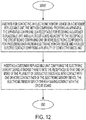
- FIG. 12 illustrates a flow diagram of a method for contacting an electronic memory device 206 on a customer replaceable unit 204, according to an embodiment of the present disclosure.
- the method comprises providing an apparatus, such as, for example, the apparatus 200 described above with respect to FIG. 9 .
- the apparatus includes (i) a receptacle 202 for receiving the customer replaceable unit 204: and (ii) a circuit board 208 adjacent to the receptacle 202.
- the circuit board 208 can include, for example, one or more electronic components 212 for processing data from an electronic memory device 206 and a roller electric contact 100 comprising a plurality of conductive discs 108, such as any of the roller electric contacts disclosed herein.
- the method further comprises inserting a customer replaceable unit 204 comprising the electronic memory device 206 attached thereto into the receptacle 202 so that one or more of the plurality of conductive discs 108 roll into contact with one or more contact pads 120 of the electronic memory device 206.
- the electronic memory device 206 thereby makes contact with the circuit board 208.
- roller electric contacts 100 of the present disclosure can reduce friction, and thereby reduce wear, between the electric contacts 100 and the contact pads.
- Electronic memory devices 206 such as printed memory, can sometimes employ relatively soft contact pads 120, such as carbon pads. Such soft contact pads may be vulnerable to damage from friction type contacts, such as conventional leaf spring contacts. By providing a rolling contact with the printed memory, damage to contact pads can be reduced or avoided compared to the damage caused by traditional leaf spring contacts that do not employ a rolling mechanism.
- FIG. 13 illustrates two identical roller electric contacts 100A and 100B positioned on a circuit board 208.
- a degree of compliance, CP is provided by the ability of roller 102 to move in the slot 124 from a first position, shown by roller 102A of roller electric contact 100A, in which the leaf springs 112 are extended as compared to a second position, shown by roller 102B of roller electric contact 100B, in which the leaf springs 112 are compressed.
- the degree of compliance provided is the difference in height of the roller 102 between the first position and the second position.
- the compliance provided by this movement allows electrical contact to be made to contact pads at varying distances from the circuit board 208 that are within the zone of compliance, CP.
- the methods of the present disclosure can be employed with any of the apparatuses and associated customer replaceable units, as described herein.
- the phrase "printing device” as used herein encompasses any apparatus, such as a digital copier, bookmaking machine, facsimile machine, multi-function machine, laser printer, inkjet printer and the like, which employs a customer replaceable unit and performs a print outputting function for any purpose.
Landscapes
- Physics & Mathematics (AREA)
- General Physics & Mathematics (AREA)
- Engineering & Computer Science (AREA)
- Computer Hardware Design (AREA)
- Electromagnetism (AREA)
- Electrophotography Configuration And Component (AREA)
Abstract
Description
- The present disclosure is directed to a roller electric contact, an apparatus for employing the roller electric contact and a method of contacting electronic devices using the roller electric contact.
- There are various types of conventional mechanisms for temporarily making electrical contact with electronic devices. One example of such a mechanism is a leaf spring contact, which allows an electronic device to be slid into place in a position where a conductive leaf spring provides spring loading force that allows good contact with the contact pads of the electronic device. However, these types of leaf spring mechanisms can cause damage due to the friction of the leaf spring rubbing against the electronic device as the device is positioned in physical contact therewith.
- Other types of contact mechanisms involve contact through a wheel, such as is disclosed in
U.S. Patent 6,040,705 . However, such mechanisms are complicated and costly. Further, due to their complexity, such wheel contact mechanisms are not easily designed for making contact to very small electronic devices. - Accordingly, novel contacts that can address one or more of the problems of the prior art mechanism would be a welcome advancement in the art.
- An embodiment of the present disclosure is directed to a roller electric contact. The roller electric contact comprises a roller comprising a shaft and a plurality of conductive discs electrically separated by an insulating material, the shaft extending through a rotational axis of the roller. A housing comprises slots in which the shaft of the roller is positioned, the slots configured to direct a non-rotational movement of the roller. A plurality of leaf springs are disposed in the housing. The leaf springs comprise an electrically conductive material. The plurality of conductive discs are spaced on the roller so that at least one of the conductive discs contact each of the plurality of leaf springs. A plurality of conductive wires extend from the roller electric contact, each of the plurality of conductive wires making electrical contact with one of the leaf springs.
- Another embodiment of the present disclosure is directed to an apparatus. The apparatus comprises a receptacle for receiving a customer replaceable unit and a circuit board adjacent to the receptacle. The circuit board comprises a first roller electric contact. The first roller electric contact comprises a roller comprising a shaft and a plurality of conductive discs electrically separated by an insulating material, the shaft extending through a rotational axis of the roller. A housing comprises slots in which the shaft of the roller is positioned, the slots configured to direct a non-rotational movement of the roller. A plurality of leaf springs are disposed in the housing, the leaf springs comprising an electrically conductive material. The plurality of conductive discs are spaced on the roller so that at least one of the conductive discs contact each of the plurality of leaf springs. A plurality of conductive wires extend from the first roller electric contact, each of the plurality of conductive wires establishing an electrical contact between one of the leaf springs and the circuit board.
- Still another embodiment of the present disclosure is directed to a method for contacting an electronic memory device on a customer replaceable unit. The method comprises providing an apparatus comprising (i) a receptacle for receiving the customer replaceable unit: and (ii) a circuit board adjacent to the receptacle. The circuit board comprises one or more electronic components for processing data from an electronic memory device and a roller electric contact comprising a plurality of conductive discs. The method includes inserting a customer replaceable unit comprising the electronic memory device attached thereto into the receptacle so that one or more of the plurality of conductive discs roll into contact with one or more contact pads of the electronic memory device. In this manner, the electronic memory device makes contact with the circuit board.
-
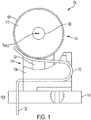
FIG. 1 illustrates a schematic, cross-sectional view of a roller electric contact, according to an embodiment of the present disclosure. -
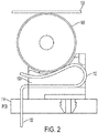
FIG. 2 illustrates a schematic, cross-sectional view of the roller electric contact ofFIG. 1 contacting a contact pad, according to an embodiment of the present disclosure. -
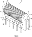
FIG. 3 illustrates a perspective view of a roller electric contact, according to an embodiment of the present disclosure. -
FIG. 4 illustrates a perspective view of a roller electric contact, according to an embodiment of the present disclosure. -
FIG. 5 illustrates a top view of an electronic memory device. -
FIG. 6 illustrates a schematic cross-sectional view of a roller, according to an embodiment of the present disclosure. -
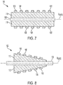
FIG. 7 illustrates a schematic cross-sectional view of a roller, according to an embodiment of the present disclosure. -
FIG. 8 illustrates a schematic cross-sectional view of a conical roller, according to an embodiment of the present disclosure. -
FIG. 9 illustrates a block diagram of an apparatus, according to an embodiment of the present disclosure -
FIG. 10 illustrates a schematic perspective view of a circuit board on which two roller electric contacts are contacting an electronic memory device, according to an embodiment of the present disclosure. -
FIG. 11 illustrates a schematic close-up perspective view of a portion of a circuit board on which two roller electric contacts are contacting an electronic memory device, according to an embodiment of the present disclosure. -
FIG. 12 illustrates a flow diagram of a method for contacting an electronic memory device using a roller electric contact, according to an embodiment of the present disclosure -
FIG. 13 illustrates a schematic side view of a portion of a circuit board on which two roller electric contacts are disposed, according to an embodiment of the present disclosure. - Reference will now be made in detail to embodiments of the present teachings, examples of which are illustrated in the accompanying drawings. In the drawings, like reference numerals have been used throughout to designate identical elements. In the following description, reference is made to the accompanying drawing that forms a part thereof, and in which is shown by way of illustration a specific exemplary embodiment in which the present teachings may be practiced. The following description is, therefore, merely exemplary.
- Unless otherwise indicated, the terms insulating, insulative, insulate, conducting, conductive, conduct, and other related words are used herein in their electrical sense (e.g., meaning "electrically insulating" or "electrically conducting"), as opposed to other possible meanings, such as those related to heat or sound.
-
FIGS. 1 to 4 illustrate various views of a rollerelectric contact 100, according to an embodiment of the present disclosure. The rollerelectric contact 100 comprises aroller 102 disposed in ahousing 104. Theroller 102 comprises ashaft 106 and a plurality ofconductive discs 108 electrically separated by aninsulating material 110. A plurality ofleaf springs 112 comprising an electrically conductive material are also disposed in thehousing 104. Theleaf springs 112 are electrically connected to acircuit board 114. The rollerelectrical contact 100 can conduct electricity from theconductive discs 108 through theleaf spring 112 to make contact between thecircuit board 114 and a contact pad 120 (FIG. 2 ) of an electronic device, such as a printed circuit. In this way, rollerelectrical contact 100 functions as an electrical contact for thecircuit board 114. - The
shaft 106 extends through a rotational axis of theroller 102 and can comprise any suitable rigid material. Examples of suitable materials can include metals, such as steel, or a rigid plastic, such as acetal or other polymers. If theshaft 106 is conductive, it is electrically insulated form the plurality ofconductive discs 108. - The plurality of
conductive discs 108 are spaced on theroller 102 so that at least one of theconductive discs 108 can electronically contact each of the plurality ofleaf springs 112. As examples, one, two, three or moreconductive discs 108 can contact eachleaf spring 112. Theconductive discs 108 can optionally protrude from theinsulating material 110 to enhance electrical contact with theleaf springs 112 and/orcontact pads 120. - The pitch, P, of the conductive discs, which refers to the distance in the direction of the Raxis of the
roller 102 separating analogous features ofadjacent discs 108, is determined by the width, Wc, of the conductive discs and spacing, Wl, therebetween, as illustrated inFIG. 6 . The pitch can be chosen to provide ease of contact with relatively small contact pads and/or to allow for relatively narrow spacing between thecontact pads 120. In many electronic devices, such as the conventional printed memory ofFIG. 5 , a plurality ofcontact pads 120 can be arranged together in a very small space, which can make it difficult to align with each contact pad separately in order to provide reliable contact to the devices. By adjusting the pitch of theconductive discs 108, the design of the rollerelectric contact 100 can allow for contact with relatively closely spaced contact pads. As is more clearly illustrated inFIG. 11 , by choosing a pitch, "p", for theconductive discs 108 that is smaller than both the width, Wp, of thecontact pads 120 and the width, WL, ofleaf springs 112, horizontal alignment between theconductive discs 108 with thecontact pads 120 of an electronic device becomes easier. Example dimensions for the pitch can range from about 0.01 mm to about 1 mm, such as about 0.02 mm to about 0.5 mm, or about 0.05 mm to about 0.3 mm. Example dimensions for Wc can range from about 0.01 mm to about 1 mm, or about 0.02 mm to about 0.5 mm, or about 0.03 mm to about 0.2 mm. Example dimensions for the Wi can range from about 0.01 mm to about 1 mm, or about 0.02 mm to about 0.5 mm, or about 0.02 mm to about 0.2 mm. - The
conductive discs 108 are electrically insulated from adjacentconductive discs 108 and theshaft 106. The insulatingmaterial 110 may cover theshaft 106 and haveconductive discs 108 embedded therein so that the plurality of conductingdiscs 108 protrude from the surface of, and extend substantially around the circumference of, theroller 102. Other conductors, such as wires (not shown) can also be embedded in the insulatingmaterial 110. - In an embodiment, the insulating
material 110 comprises an elastomer. Examples of suitable elastomers include silicone, TPU (thermoplastic polyurethane), EPDM (ethylene propylene diene monomer) rubbers and mixtures of any two or more of these elastomers. - In an embodiment, the insulating
material 110 of the roller is in a form of a plurality of insulatingdiscs 122 positioned between theconductive discs 108.FIG. 6 illustrates a cross-sectional view of one such embodiment in which theconductive discs 108 are supported by the insulatingdiscs 122 comprising an elastomer. The durometer of the elastomer is chosen to provide relative compliance between neighboringconductive discs 108, thereby allowing the conductive discs to adjust position relative to each other to account for variations in the topology of the surfaces being contacted. For example, insulatingdiscs 122 comprising an elastomer may be stacked (laminated) between theconductive discs 108 in such a way that the insulatingmaterial 110 is positioned primarily between theconductive discs 108, and does not extend the entire length of the axis of the roller (e.g., does not extend under the conductive discs 108), so that the conducting discs are suspended between insulatingdiscs 122. Conductingshaft 106 does not contact any of the plurality of the conductingdiscs 108. In an embodiment,gaps 123 are disposed between theconductive discs 108 andshaft 106. The gaps can be filled with any insulating material, such as air (e.g., an airgap), another gas or a vacuum, or an insulating polymer. In an embodiment,gaps 123 can be filled with the same or a different insulating material as insulatingdiscs 122. Alternatively, ifshaft 106 is insulative, any plurality of the conductingdiscs 108 can contact the insulatingshaft 106. -
FIG. 7 illustrates cross-sectional view of another embodiment ofroller 102. An insulatingmaterial 110 is disposed in alayer surrounding shaft 106, whereshaft 106 can be either conductive or insulative.Conductive discs 108 are disposed on the insulatingmaterial 110. Techniques suitable for forming the insulatingmaterial 110 in a layer onshaft 106 and for forming theconductive discs 108 are well known in the art. - In general, the
roller 102 may be formed as in integral part of theshaft 106. Alternatively, theshaft 106 may be manufactured separately from the insulatingmaterial 110 andconductive discs 108 of theroller 102 and then incorporated into theroller 102. The roller and/or shaft can be manufactured by any suitable method, such as by over-molding techniques or by punching rollers from laminate sheets. Such methods are generally well known in the art. - Specialized applications may specify some conicity of the
roller 102, so that theroller 102 rolls in a circular arc rather than a straight line. A schematic view of an example of aconical roller 102 is shown inFIG. 8 . - Referring again to
FIGS. 1 and3 , thehousing 104 can be made of any suitable material, such as plastic. Any suitable plastic that has the desired rigidity and that can otherwise support the roller can be employed. An example of such a plastic is polyoxymethylene, sometimes referred to herein as "acetal". - The
housing 104 comprisesslots 124 in which the ends of theshaft 106 ofroller 102 are positioned. Theslots 124 are configured to direct non-rotational movement of theroller 102, such as a lateral or up-and-down motion, while allowing theshaft 106 to freely rotate on a rotational axis, Raxis, of the roller. InFIG. 1 , the Raxis is shown as a dot in the center ofshaft 106 going into the page, and is more clearly shown as a dashed line inFIG. 6 . Theroller 102 is moveable in theslots 124 from a first position, shown inFIGS. 1 and3 , in which theleaf springs 112 are extended as compared to a second position, shown inFIGS. 2 and4 , in which theleaf springs 112 are compressed by theroller 102. - A
cradle 130 is positioned in thehousing 104 so as to stop the non-rotational movement of theroller 102 at the second position, as shown inFIGS. 2 and4 . Employing acradle 130 in this fashion can reduce or prevent over compression of, and potential damage to, the leaf springs 112. - A plurality of
conductive wires 132 extend from the rollerelectric contact 100. Each of the plurality ofconductive wires 132 is electrically connected with one of the leaf springs 112. In an embodiment, each of the plurality ofconductive wires 132 can be formed as a single, integral part with one of the leaf springs 112. Alternatively, theconductive wires 132 can be formed separate from theleaf springs 112 and electrically connected thereto. - The leaf springs 112 and
conductive wires 132 can comprise any suitable conductive material. Examples of suitable material for theleaf springs 112 include spring steel, gold, silver, or other metals. In an example, theleaf springs 112 may be plated. For example, theleaf springs 112 may comprise a gold or silver plated elastic material, such as spring steel, in order to provide the desired elasticity and conductivity. Theconductive wires 132 can be made from the same material, or a different material, as the leaf springs 112. - An electrically conductive carbon brush coating can optionally be employed between the
roller 102 andleaf springs 112 to reduce and/or prevent wear caused by friction of theroller 102 on the leaf springs 112. For example, the carbon brush can potentially mitigate the effects of wear so that any wear that does occur will not impede the proper function of the connector over its anticipated design life. In an embodiment, the brush coating can comprise a block of plastic impregnated with carbon. Any suitable carbon brush can be employed. Examples of suitable carbon brushes are well known in the art, such as have been employed in commutators of some electric motors. - An example method for constructing the roller
electric contacts 100 of the present disclosure includes laminating many alternating conducting and insulating layers into a sheet approximately as thick as the intended length of theroller 102, punching hollow cylinders out of the laminate with an outer diameter equal to the roller outer diameter and an inner diameter equal to theshaft 106 diameter. The hollow cylinders can then be placed in an injection-moldedhousing 104 and ashaft 106 is then press-fit into the inner diameter of the cylinder, thus capturing the roller in thehousing 104. Leaf springs 112 can be press-fit into the housing or frame. This method could employ an insulating shaft 106 (or a conductingshaft 106 coated with an insulating material). Preferably the process would be controlled so as to cause the insulating discs to retract relative to the conductingdiscs 108 after punching. Controlling temperature and/or compression during the punching process may help with this, or possibly a post-punching anneal step such as curing or heat treatment. -
FIG. 9 illustrates a block diagram of anapparatus 200, according to an embodiment of the present disclosure. Theapparatus 200 comprises areceptacle 202 for receiving a customerreplaceable unit 204. The customer replaceable unit can include anelectronic memory device 206, such as a printed memory, with data that is designed to be read by theapparatus 200. The customerreplaceable unit 204 is illustrated inFIG. 9 using dashed lines to indicate that it is a device that is separable from theapparatus 200 and is designed to be easily installed and/or removed by an operator of theapparatus 200. Acircuit board 208 is disposed adjacent to thereceptacle 202.Circuit board 208 comprises at least one rollerelectric contact 100, as described herein. The at least one rollerelectric contact 100 can be employed to establish an electrical connection between thecircuit board 208 and theelectronic memory 206 on the customerreplaceable unit 204, when the customerreplaceable unit 204 is inserted into thereceptacle 202. In addition to the at least one rollerelectric contact 100,circuit board 208 can further include any number and type ofelectronic components 212 that may be useful for the operation of theapparatus 200. For example,circuit board 208 can include one or moreelectronic components 212 for processing data fromelectronic memory device 206. - Any number of roller electric contacts can be employed on the
circuit board 208, depending on, for example, the number and configuration of contacts to be made.FIG. 10 illustrates acircuit board 208 that comprises twoelectric contacts 100. The rollerelectric contacts 100 are positioned adjacent to each other oncircuit board 208 so as to make contact with two rows ofcontact pads 120 onelectronic memory device 206. Thus, 2, 3, 4 or more rollerelectric contacts 100 can be employed on a circuit board. - Referring back to
FIG. 9 ,apparatus 200 can be any type of apparatus that would benefit from the rollerelectric contacts 100 of the present disclosure. In an embodiment,apparatus 200 is a printing device (e.g., a laser printer) and thereceptacle 202 is configured to receive a toner cartridge as the customerreplaceable unit 204. In another embodiment, theapparatus 200 is a printing device (e.g., an inkjet printer or other printer that employs ink) and thereceptacle 202 is configured to receive an ink cartridge as the customerreplaceable unit 204. In yet another embodiment, theapparatus 200 is a refrigerator and thereceptacle 202 is configured to receive a water filter as the customerreplaceable unit 204. In still another embodiment, theapparatus 200 is a beverage dispenser for dispensing coffee or other beverages and thereceptacle 202 is configured to receive a beverage container (e.g., a cup) as the customerreplaceable unit 204. Other types of apparatus that would benefit from the use of roller electric contacts of the present disclosure can be determined by one of ordinary skill in the art. - In certain applications the orientation of the customer
replaceable unit 204 bearing theelectronic memory device 206 may not be easily controlled, such as for example, in the case of a cup or other beverage container being inserted into a beverage dispenser. In such cases, anoptional orientation mechanism 210 can physically couple thecircuit board 208 to theapparatus 200, as shown inFIG. 9 . Theorientation mechanism 210 is configured to rotate or otherwise orient thecircuit board 208 and/or customerreplaceable unit 204 relative to each other such that the rollerelectric contacts 100 are positioned in possible locations of theelectronic memory device 206 on the customerreplaceable unit 204, thereby allowing the one or more rollerelectric contacts 100 to make electrical contact with theelectronic memory device 206.FIG. 9 illustrates the orientation mechanism attached to thecircuit board 208. In addition to, or in place of, theorientation mechanism 210 being attached to thecircuit board 208, an orientation mechanism can be attached to rotate or otherwise orient the customerreplaceable unit 204. Orientation mechanisms are generally well known in the art and determining and/or designing a suitable orientation mechanism for a given type ofapparatus 200 would be within the ordinary skill of the art. -
FIG. 12 illustrates a flow diagram of a method for contacting anelectronic memory device 206 on a customerreplaceable unit 204, according to an embodiment of the present disclosure. The method comprises providing an apparatus, such as, for example, theapparatus 200 described above with respect toFIG. 9 . The apparatus includes (i) areceptacle 202 for receiving the customer replaceable unit 204: and (ii) acircuit board 208 adjacent to thereceptacle 202. Thecircuit board 208 can include, for example, one or moreelectronic components 212 for processing data from anelectronic memory device 206 and a rollerelectric contact 100 comprising a plurality ofconductive discs 108, such as any of the roller electric contacts disclosed herein. The method further comprises inserting a customerreplaceable unit 204 comprising theelectronic memory device 206 attached thereto into thereceptacle 202 so that one or more of the plurality ofconductive discs 108 roll into contact with one ormore contact pads 120 of theelectronic memory device 206. Theelectronic memory device 206 thereby makes contact with thecircuit board 208. - Employing the roller
electric contacts 100 of the present disclosure to make contact withcontact pads 120 can reduce friction, and thereby reduce wear, between theelectric contacts 100 and the contact pads.Electronic memory devices 206, such as printed memory, can sometimes employ relativelysoft contact pads 120, such as carbon pads. Such soft contact pads may be vulnerable to damage from friction type contacts, such as conventional leaf spring contacts. By providing a rolling contact with the printed memory, damage to contact pads can be reduced or avoided compared to the damage caused by traditional leaf spring contacts that do not employ a rolling mechanism. -
FIG. 13 illustrates two identical rollerelectric contacts circuit board 208. A degree of compliance, CP, is provided by the ability ofroller 102 to move in theslot 124 from a first position, shown byroller 102A of rollerelectric contact 100A, in which theleaf springs 112 are extended as compared to a second position, shown byroller 102B of rollerelectric contact 100B, in which theleaf springs 112 are compressed. Thus, the degree of compliance provided is the difference in height of theroller 102 between the first position and the second position. The compliance provided by this movement allows electrical contact to be made to contact pads at varying distances from thecircuit board 208 that are within the zone of compliance, CP. - The methods of the present disclosure can be employed with any of the apparatuses and associated customer replaceable units, as described herein. The phrase "printing device" as used herein encompasses any apparatus, such as a digital copier, bookmaking machine, facsimile machine, multi-function machine, laser printer, inkjet printer and the like, which employs a customer replaceable unit and performs a print outputting function for any purpose.
- Notwithstanding that the numerical ranges and parameters setting forth the broad scope of the disclosure are approximations, the numerical values set forth in the specific examples are reported as precisely as possible. Any numerical value, however, inherently contains certain errors necessarily resulting from the standard deviation found in their respective testing measurements. Moreover, all ranges disclosed herein are to be understood to encompass any and all sub-ranges subsumed therein.
Claims (20)
- A roller electric contact, comprising:a roller comprising a shaft and a plurality of conductive discs electrically separated by an insulating material, the shaft extending through a rotational axis of the roller;a housing comprising slots in which the shaft of the roller is positioned, the slots configured to direct a non-rotational movement of the roller; anda plurality of leaf springs disposed in the housing, the leaf springs comprising an electrically conductive material, the plurality of conductive discs being spaced on the roller so that at least one of the conductive discs contact each of the plurality of leaf springs; anda plurality of conductive wires extending from the roller electric contact, each of the plurality of conductive wires making electrical contact with one of the leaf springs.
- The roller electric contact of claim 1, wherein the roller is moveable in the slots from a first position at which the leaf springs are extended relative to a second position at which the leaf springs are compressed by the roller.
- The roller electric contact of claim 2, further comprising a cradle disposed to stop a motion of the roller at the second position.
- The roller electric contact of claim 1, wherein the insulating material is in a form of a plurality of insulating discs.
- The roller electric contact of claim 1, wherein the insulating material comprises an elastomer.
- The roller electric contact of claim 1, wherein each of the plurality of conductive wires forms a single, integral part with one of the leaf springs.
- An apparatus, comprising:a receptacle for receiving a customer replaceable unit: anda circuit board adjacent to the receptacle, the circuit board comprising a first roller electric contact, the first roller electric contact comprising:a roller comprising a shaft and a plurality of conductive discs electrically separated by an insulating material, the shaft extending through a rotational axis of the roller;a housing comprising slots in which the shaft of the roller is positioned, the slots configured to direct a non-rotational movement of the roller; anda plurality of leaf springs disposed in the housing, the leaf springs comprising an electrically conductive material, the plurality of conductive discs being spaced on the roller so that at least one of the conductive discs contact each of the plurality of leaf springs; anda plurality of conductive wires extending from the first roller electric contact, each of the plurality of conductive wires establishing an electrical contact between one of the leaf springs and the circuit board.
- The apparatus of claim 7, wherein the circuit board further comprises a second roller electric contact adjacent to the first roller electric contact.
- The apparatus of claim 7, wherein the apparatus is a printing device and the receptacle is configured to receive a toner cartridge.
- The apparatus of claim 7, wherein the apparatus is a printing device and the receptacle is configured to receive an ink cartridge.
- The apparatus of claim 7, wherein the apparatus is a refrigerator and the receptacle is configured to receive a water filter.
- The apparatus of claim 7, wherein the roller is moveable in the slots from a first position at which the leaf springs are extended relative to a second position at which the leaf springs are compressed by the roller.
- The apparatus of claim 7, wherein the insulating material is in a form of a plurality of insulating discs.
- The apparatus of claim 7, wherein the insulating material comprises an elastomer.
- The apparatus of claim 7, wherein each of the plurality of conductive wires forms a single, integral part with one of the leaf springs.
- A method for contacting an electronic memory device on a customer replaceable unit, the method comprising:providing an apparatus comprising (i) a receptacle for receiving the customer replaceable unit: and (ii) a circuit board adjacent to the receptacle, the circuit board comprising one or more electronic components for processing data from an electronic memory device and a roller electric contact comprising a plurality of conductive discs, andinserting a customer replaceable unit comprising the electronic memory device attached thereto into the receptacle so that one or more of the plurality of conductive discs roll into contact with one or more contact pads of the electronic memory device, the electronic memory device thereby making contact with the circuit board.
- The method of claim 16, wherein the apparatus is a printing device and the customer replaceable unit is a toner cartridge.
- The method of claim 16, wherein the apparatus is a printing device and the customer replaceable unit is an ink cartridge.
- The method of claim 16, wherein the apparatus is a refrigerator and the customer replaceable unit is a water filter.
- The method of claim 16, wherein the roller electric contact comprises:a roller comprising a shaft and the plurality of conductive discs electrically separated by an insulating material, the shaft extending through a rotational axis of the roller;a housing comprising slots in which the shaft of the roller is positioned, the slots configured to direct a non-rotational movement of the roller; anda plurality of leaf springs disposed in the housing, the leaf springs comprising an electrically conductive material, the plurality of conductive discs being spaced on the roller so that at least one of the conductive discs contact each of the plurality of leaf springs; anda plurality of conductive wires extending from the roller electric contact, each of the plurality of conductive wires establishing an electrical contact between one of the leaf springs and the circuit board.
Applications Claiming Priority (1)
| Application Number | Priority Date | Filing Date | Title |
|---|---|---|---|
| US16/173,600 US10497521B1 (en) | 2018-10-29 | 2018-10-29 | Roller electric contact |
Publications (2)
| Publication Number | Publication Date |
|---|---|
| EP3657615A2 true EP3657615A2 (en) | 2020-05-27 |
| EP3657615A3 EP3657615A3 (en) | 2020-10-07 |
Family
ID=68344635
Family Applications (1)
| Application Number | Title | Priority Date | Filing Date |
|---|---|---|---|
| EP19205221.5A Withdrawn EP3657615A3 (en) | 2018-10-29 | 2019-10-24 | Roller electric contact |
Country Status (6)
| Country | Link |
|---|---|
| US (1) | US10497521B1 (en) |
| EP (1) | EP3657615A3 (en) |
| JP (1) | JP2020072086A (en) |
| KR (1) | KR20200049555A (en) |
| CN (1) | CN111106498A (en) |
| RU (1) | RU2019133318A (en) |
Citations (1)
| Publication number | Priority date | Publication date | Assignee | Title |
|---|---|---|---|---|
| US6040705A (en) | 1997-08-20 | 2000-03-21 | Electro Scientific Industries, Inc. | Rolling electrical contactor |
Family Cites Families (24)
| Publication number | Priority date | Publication date | Assignee | Title |
|---|---|---|---|---|
| US1919119A (en) * | 1929-07-02 | 1933-07-18 | Arrow Hart & Hegeman Electric | Tumbler switch |
| FR1581508A (en) * | 1968-04-12 | 1969-09-19 | ||
| US4004136A (en) * | 1975-03-24 | 1977-01-18 | Bell Telephone Laboratories, Incorporated | Credit verification terminal with dual information sources |
| US4149049A (en) * | 1977-12-14 | 1979-04-10 | Cutler-Hammer, Inc. | Switch using resilient annular contactor |
| US4943224A (en) * | 1989-02-10 | 1990-07-24 | General Electric Company | Apparatus employing integral dielectric heater for roll forming thermoplastic material |
| NO972803D0 (en) | 1997-06-17 | 1997-06-17 | Opticom As | Electrically addressable logic device, method of electrically addressing the same and use of device and method |
| NO308149B1 (en) | 1998-06-02 | 2000-07-31 | Thin Film Electronics Asa | Scalable, integrated data processing device |
| GB2341983B (en) * | 1998-09-24 | 2002-04-10 | Taiko Denki Co Ltd | Smart card interfaces |
| JP2001015241A (en) * | 1999-07-01 | 2001-01-19 | Sony Corp | Leaf spring type energizing brush |
| NO312699B1 (en) | 2000-07-07 | 2002-06-17 | Thin Film Electronics Asa | Addressing memory matrix |
| NO312698B1 (en) | 2000-07-07 | 2002-06-17 | Thin Film Electronics Asa | Method for performing write and read operations in a passive matrix memory and apparatus for performing the method |
| NO20004237L (en) | 2000-08-24 | 2002-02-25 | Thin Film Electronics Asa | Integrated detection amplifier |
| US6714028B2 (en) * | 2001-11-14 | 2004-03-30 | Electro Scientific Industries, Inc. | Roller contact with conductive brushes |
| US6878980B2 (en) | 2001-11-23 | 2005-04-12 | Hans Gude Gudesen | Ferroelectric or electret memory circuit |
| NO314524B1 (en) | 2001-11-30 | 2003-03-31 | Thin Film Electronics Asa | Method of reading cells in a passive matrix addressable device, and device for carrying out the method |
| DE60322603D1 (en) * | 2002-03-28 | 2008-09-11 | Brother Ind Ltd | printing device |
| NO317905B1 (en) | 2002-09-11 | 2004-12-27 | Thin Film Electronics Asa | Method for operating ferroelectric or electret memory device and a device of this kind |
| US7193881B2 (en) | 2004-07-01 | 2007-03-20 | Thin Film Electronics Asa | Cross-point ferroelectric memory that reduces the effects of bit line to word line shorts |
| JP2006058129A (en) * | 2004-08-19 | 2006-03-02 | Enegate:Kk | Connector for watt-hour meter |
| US7839138B2 (en) * | 2007-01-29 | 2010-11-23 | Electro Scientific Industries, Inc. | Adjustable force electrical contactor |
| JP2009000334A (en) * | 2007-06-22 | 2009-01-08 | Hoya Corp | Endoscope connector device |
| KR101622601B1 (en) * | 2009-02-19 | 2016-05-20 | 엘지전자 주식회사 | Refrigerator and apparatus for sensing ice full state thereof |
| US20100273355A1 (en) * | 2009-04-22 | 2010-10-28 | Tyco Electronics Corporation | Image guide wire connection |
| JP5094823B2 (en) * | 2009-12-02 | 2012-12-12 | 株式会社沖データ | Image forming apparatus |
-
2018
- 2018-10-29 US US16/173,600 patent/US10497521B1/en not_active Expired - Fee Related
-
2019
- 2019-10-08 JP JP2019184859A patent/JP2020072086A/en not_active Ceased
- 2019-10-10 CN CN201910960834.XA patent/CN111106498A/en active Pending
- 2019-10-21 RU RU2019133318A patent/RU2019133318A/en unknown
- 2019-10-22 KR KR1020190131112A patent/KR20200049555A/en not_active Abandoned
- 2019-10-24 EP EP19205221.5A patent/EP3657615A3/en not_active Withdrawn
Patent Citations (1)
| Publication number | Priority date | Publication date | Assignee | Title |
|---|---|---|---|---|
| US6040705A (en) | 1997-08-20 | 2000-03-21 | Electro Scientific Industries, Inc. | Rolling electrical contactor |
Also Published As
| Publication number | Publication date |
|---|---|
| KR20200049555A (en) | 2020-05-08 |
| US10497521B1 (en) | 2019-12-03 |
| CN111106498A (en) | 2020-05-05 |
| RU2019133318A (en) | 2021-04-21 |
| EP3657615A3 (en) | 2020-10-07 |
| JP2020072086A (en) | 2020-05-07 |
Similar Documents
| Publication | Publication Date | Title |
|---|---|---|
| US11237503B2 (en) | Heater configured to maintain adequate contact pressure with a contact terminal, heating device, fixing device, and image forming apparatus | |
| EP3751353B1 (en) | Heating device, fixing device, and image forming apparatus | |
| US10747154B2 (en) | Fixing device and image forming apparatus | |
| CN113196182A (en) | Heating device, belt heating device, fixing device, and image forming apparatus | |
| US20110217093A1 (en) | Fixing device and image forming apparatus incorporating same | |
| JP2022140086A (en) | Fixing device and image forming apparatus | |
| US20230010218A1 (en) | Heating device, fixing device, and image forming apparatus | |
| US10884366B2 (en) | Heater, fixing device, and image forming apparatus | |
| WO2005112055A2 (en) | Contact assembly | |
| US8781378B2 (en) | Fixing device and image forming apparatus | |
| US10281857B1 (en) | Fixing device and image forming apparatus | |
| US10497521B1 (en) | Roller electric contact | |
| US20070154232A1 (en) | Contacting removable printer cartridges | |
| JP2020008811A (en) | Fixing device and image forming apparatus | |
| US7559550B2 (en) | Paper-discharging apparatus used with an image-forming device | |
| JP2011173724A (en) | Sheet feeding device and image forming apparatus | |
| US20030063174A1 (en) | Sheet conveying device and image forming apparatus including the same | |
| KR100785474B1 (en) | Apparatus for manufacturing image drum and manufacturing method using same | |
| CA1258087A (en) | Electrographic charge deposition apparatus | |
| CN100557088C (en) | Apparatus for electroetching printed circuit boards | |
| US7603070B2 (en) | Heat roller of image forming apparatus | |
| US20190056684A1 (en) | Fixing device and image forming apparatus | |
| US10209655B2 (en) | Film for use in fixing device and fixing device with film | |
| JP2022131694A (en) | Fixing device and image forming device | |
| JP5015659B2 (en) | Fixing device |
Legal Events
| Date | Code | Title | Description |
|---|---|---|---|
| PUAI | Public reference made under article 153(3) epc to a published international application that has entered the european phase |
Free format text: ORIGINAL CODE: 0009012 |
|
| STAA | Information on the status of an ep patent application or granted ep patent |
Free format text: STATUS: THE APPLICATION HAS BEEN PUBLISHED |
|
| AK | Designated contracting states |
Kind code of ref document: A2 Designated state(s): AL AT BE BG CH CY CZ DE DK EE ES FI FR GB GR HR HU IE IS IT LI LT LU LV MC MK MT NL NO PL PT RO RS SE SI SK SM TR |
|
| AX | Request for extension of the european patent |
Extension state: BA ME |
|
| PUAL | Search report despatched |
Free format text: ORIGINAL CODE: 0009013 |
|
| AK | Designated contracting states |
Kind code of ref document: A3 Designated state(s): AL AT BE BG CH CY CZ DE DK EE ES FI FR GB GR HR HU IE IS IT LI LT LU LV MC MK MT NL NO PL PT RO RS SE SI SK SM TR |
|
| AX | Request for extension of the european patent |
Extension state: BA ME |
|
| RIC1 | Information provided on ipc code assigned before grant |
Ipc: H01H 1/24 20060101ALI20200902BHEP Ipc: H01R 39/28 20060101AFI20200902BHEP Ipc: G03G 15/08 20060101ALI20200902BHEP Ipc: G03G 21/16 20060101ALI20200902BHEP Ipc: G11C 11/50 20060101ALI20200902BHEP Ipc: H01H 1/16 20060101ALI20200902BHEP |
|
| STAA | Information on the status of an ep patent application or granted ep patent |
Free format text: STATUS: REQUEST FOR EXAMINATION WAS MADE |
|
| 17P | Request for examination filed |
Effective date: 20210407 |
|
| RBV | Designated contracting states (corrected) |
Designated state(s): AL AT BE BG CH CY CZ DE DK EE ES FI FR GB GR HR HU IE IS IT LI LT LU LV MC MK MT NL NO PL PT RO RS SE SI SK SM TR |
|
| GRAP | Despatch of communication of intention to grant a patent |
Free format text: ORIGINAL CODE: EPIDOSNIGR1 |
|
| STAA | Information on the status of an ep patent application or granted ep patent |
Free format text: STATUS: GRANT OF PATENT IS INTENDED |
|
| INTG | Intention to grant announced |
Effective date: 20230124 |
|
| STAA | Information on the status of an ep patent application or granted ep patent |
Free format text: STATUS: THE APPLICATION IS DEEMED TO BE WITHDRAWN |
|
| 18D | Application deemed to be withdrawn |
Effective date: 20230606 |