EP3657610B1 - Electrical connector assembly - Google Patents
Electrical connector assembly Download PDFInfo
- Publication number
- EP3657610B1 EP3657610B1 EP19205603.4A EP19205603A EP3657610B1 EP 3657610 B1 EP3657610 B1 EP 3657610B1 EP 19205603 A EP19205603 A EP 19205603A EP 3657610 B1 EP3657610 B1 EP 3657610B1
- Authority
- EP
- European Patent Office
- Prior art keywords
- housing
- assembly
- slot
- fins
- axis
- Prior art date
- Legal status (The legal status is an assumption and is not a legal conclusion. Google has not performed a legal analysis and makes no representation as to the accuracy of the status listed.)
- Active
Links
Images




Classifications
-
- H—ELECTRICITY
- H01—ELECTRIC ELEMENTS
- H01R—ELECTRICALLY-CONDUCTIVE CONNECTIONS; STRUCTURAL ASSOCIATIONS OF A PLURALITY OF MUTUALLY-INSULATED ELECTRICAL CONNECTING ELEMENTS; COUPLING DEVICES; CURRENT COLLECTORS
- H01R13/00—Details of coupling devices of the kinds covered by groups H01R12/70 or H01R24/00 - H01R33/00
- H01R13/40—Securing contact members in or to a base or case; Insulating of contact members
- H01R13/42—Securing in a demountable manner
- H01R13/436—Securing a plurality of contact members by one locking piece or operation
-
- H—ELECTRICITY
- H01—ELECTRIC ELEMENTS
- H01R—ELECTRICALLY-CONDUCTIVE CONNECTIONS; STRUCTURAL ASSOCIATIONS OF A PLURALITY OF MUTUALLY-INSULATED ELECTRICAL CONNECTING ELEMENTS; COUPLING DEVICES; CURRENT COLLECTORS
- H01R13/00—Details of coupling devices of the kinds covered by groups H01R12/70 or H01R24/00 - H01R33/00
- H01R13/46—Bases; Cases
- H01R13/502—Bases; Cases composed of different pieces
-
- H—ELECTRICITY
- H01—ELECTRIC ELEMENTS
- H01R—ELECTRICALLY-CONDUCTIVE CONNECTIONS; STRUCTURAL ASSOCIATIONS OF A PLURALITY OF MUTUALLY-INSULATED ELECTRICAL CONNECTING ELEMENTS; COUPLING DEVICES; CURRENT COLLECTORS
- H01R13/00—Details of coupling devices of the kinds covered by groups H01R12/70 or H01R24/00 - H01R33/00
- H01R13/46—Bases; Cases
- H01R13/533—Bases, cases made for use in extreme conditions, e.g. high temperature, radiation, vibration, corrosive environment, pressure
-
- H—ELECTRICITY
- H01—ELECTRIC ELEMENTS
- H01R—ELECTRICALLY-CONDUCTIVE CONNECTIONS; STRUCTURAL ASSOCIATIONS OF A PLURALITY OF MUTUALLY-INSULATED ELECTRICAL CONNECTING ELEMENTS; COUPLING DEVICES; CURRENT COLLECTORS
- H01R13/00—Details of coupling devices of the kinds covered by groups H01R12/70 or H01R24/00 - H01R33/00
- H01R13/62—Means for facilitating engagement or disengagement of coupling parts or for holding them in engagement
- H01R13/627—Snap or like fastening
- H01R13/6278—Snap or like fastening comprising a pin snapping into a recess
-
- H—ELECTRICITY
- H01—ELECTRIC ELEMENTS
- H01R—ELECTRICALLY-CONDUCTIVE CONNECTIONS; STRUCTURAL ASSOCIATIONS OF A PLURALITY OF MUTUALLY-INSULATED ELECTRICAL CONNECTING ELEMENTS; COUPLING DEVICES; CURRENT COLLECTORS
- H01R13/00—Details of coupling devices of the kinds covered by groups H01R12/70 or H01R24/00 - H01R33/00
- H01R13/62—Means for facilitating engagement or disengagement of coupling parts or for holding them in engagement
- H01R13/629—Additional means for facilitating engagement or disengagement of coupling parts, e.g. aligning or guiding means, levers, gas pressure electrical locking indicators, manufacturing tolerances
- H01R13/62933—Comprising exclusively pivoting lever
- H01R13/62944—Pivoting lever comprising gear teeth
-
- H—ELECTRICITY
- H01—ELECTRIC ELEMENTS
- H01R—ELECTRICALLY-CONDUCTIVE CONNECTIONS; STRUCTURAL ASSOCIATIONS OF A PLURALITY OF MUTUALLY-INSULATED ELECTRICAL CONNECTING ELEMENTS; COUPLING DEVICES; CURRENT COLLECTORS
- H01R13/00—Details of coupling devices of the kinds covered by groups H01R12/70 or H01R24/00 - H01R33/00
- H01R13/62—Means for facilitating engagement or disengagement of coupling parts or for holding them in engagement
- H01R13/629—Additional means for facilitating engagement or disengagement of coupling parts, e.g. aligning or guiding means, levers, gas pressure electrical locking indicators, manufacturing tolerances
- H01R13/62933—Comprising exclusively pivoting lever
- H01R13/62955—Pivoting lever comprising supplementary/additional locking means
-
- H—ELECTRICITY
- H01—ELECTRIC ELEMENTS
- H01R—ELECTRICALLY-CONDUCTIVE CONNECTIONS; STRUCTURAL ASSOCIATIONS OF A PLURALITY OF MUTUALLY-INSULATED ELECTRICAL CONNECTING ELEMENTS; COUPLING DEVICES; CURRENT COLLECTORS
- H01R13/00—Details of coupling devices of the kinds covered by groups H01R12/70 or H01R24/00 - H01R33/00
- H01R13/62—Means for facilitating engagement or disengagement of coupling parts or for holding them in engagement
- H01R13/639—Additional means for holding or locking coupling parts together, after engagement, e.g. separate keylock, retainer strap
-
- H—ELECTRICITY
- H01—ELECTRIC ELEMENTS
- H01R—ELECTRICALLY-CONDUCTIVE CONNECTIONS; STRUCTURAL ASSOCIATIONS OF A PLURALITY OF MUTUALLY-INSULATED ELECTRICAL CONNECTING ELEMENTS; COUPLING DEVICES; CURRENT COLLECTORS
- H01R24/00—Two-part coupling devices, or either of their cooperating parts, characterised by their overall structure
- H01R24/005—Two-part coupling devices, or either of their cooperating parts, characterised by their overall structure requiring successive relative motions to complete the coupling, e.g. bayonet type
Definitions
- This disclosure generally relates to an electrical connector, and more particularly relates to an electrical connector with a high vibration resistant locking mechanism.
- Publication EP 3 142 194 A1 discloses a connector assembly comprising a first connector having a first housing and an intermediate housing attached to the first housing.
- the intermediate housing is moveable from a first position to a second position.
- a flexible retaining arm is configured to hold the intermediate housing in the first position.
- the connector assembly further includes a second connector having a second housing.
- the second housing defines a release wedge that engages and flexes the retaining arm, thereby releasing the intermediate housing from engagement with the retaining arm and allowing the intermediate housing to move from the first position to the second position as the first connector is connected to the second connector.
- a terminal in the first housing is enclosed within the intermediate housing in the first position, and protrudes from an aperture in a surface of the intermediate housing in the second position.
- Publication EP 2 889 966 A1 discloses a lever-actuated connector having a wire cover to which a lever is attached so as to be rotatable between an initial mating position and a final mating position, and a housing to which the wire cover is mounted.
- An interference structure is provided between the lever and the housing, the interference structure arranged to prevent the wire cover, having the lever placed in a position for mounting the wire cover to the housing, from being mounted to the housing with an improper orientation.
- WO 2012/011604 A1 discloses a lever type connector including a connector housing to be engaged with a mating connecter housing, a spacer, a lever including a cam groove and turnably attached to the connector housing, a terminal to be inserted into a rear end surface of the connector housing, a positioning lock provided in the lever to temporarily fix the lever to be attached to the connector housing, a jig passing space formed in the positioning lock, and a spacer pushing surface provided on an upper side of the spacer.
- the spacer pushing surface is formed in symmetrical position to the jig passing space.
- the spacer pushing surfaces are pushed by pushing pins which are provided on the jig in bilaterally symmetrical positions with respect to a center line that intersects orthogonally with the longitudinal direction of the spacer.
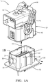
- Fig. 1A is a perspective exploded view illustrating an electrical connector-assembly 10, hereafter referred to as the assembly 10.
- the assembly 10 is an improvement over other connector assemblies, because the assembly 10 resists high vibrations by limiting a movement between connector housings.
- the assembly 10 includes a first-housing 12 that has first-walls 14 aligned parallel to a mating-axis 16 of the assembly 10.
- the first-housing 12 is formed of a polymeric dielectric material.
- the polymeric dielectric material may be any polymeric dielectric material capable of electrically isolating portions of electrical-terminals 18 (see Fig. 4 ) retained by the first-housing 12, and is preferably a polyamide (NYLON) material.
- the first-walls 14 include opposed gear-racks 20 extending beyond an outer-surface 22 of the first-walls 14 along a lateral-axis 24 and aligned with the mating-axis 16.
- the opposed gear-racks 20 are configured to engage a mate-assist device 26 mounted on a second-housing 28, as will be described in more detail below.
- the first-walls 14 include opposed locking-fins 30, hereafter referred to as the locking-fins 30, extending along a longitudinal-axis 32 beyond the outer-surface 22 and are aligned with the mating-axis 16.
- the locking-fins 30 have first-fins 34 and second-fins 36 aligned with the mating-axis 16, with the first-fin 34 positioned superior to (i.e. above, distal to, etc.) the second-fin 36, as illustrated in Figs. 1A-1B .
- the first-housing 12 includes a single pair of opposed first-fin 34 and second-fin 36 pairs. In the example illustrated in Fig.
- the first-housing 12 further includes a plurality of opposed first-fin 34 and second-fin 36 pairs that are located on opposite sides of the first-housing 12 from one another.
- the first-fins 34 and the second-fins 36 define first-angles 38 and second-angles 40 (see Fig. 1B ), with the first-angles 38 less than the second-angles 40, the function of which will be described in more detail below.
- the first-angles 38 are in a range between 15-degrees and 30-degrees
- the second-angles 40 are in the range between 30-degrees and 60-degrees.
- the assembly 10 also includes the second-housing 28 configured to retain corresponding electrical-terminals 42 that are configured to mate with the electrical-terminals 18 of the first-housing 12 (see Fig. 4 ).
- the second-housing 28 is preferably formed of the same polymeric dielectric material as the first-housing 12, but may be any polymeric dielectric material.
- the second-housing 28 includes the mate-assist device 26 which is moveable from an unlocked-position 44 to a locked-position 46 (see Fig. 3 ). In the example illustrated in Fig. 1 , the mate-assist device 26 is in the unlocked-position 44.
- the mate-assist device 26 is pivotable about the lateral-axis 24 and includes gear-teeth 48 configured to engage the opposed gear-racks 20 of the first-housing 12.
- the mate-assist device 26 reversibly locks in the locked-position 46 to a locking-lug extending from a wire dress cover (not specifically shown) that forms the top of the second-housing 28.
- Fig. 2 illustrates the assembly 10 in a prestage-position 50.
- the second-housing 28 has a skirt 52 aligned with (i.e. parallel to) the mating-axis 16.
- the skirt 52 is configured to slideably engage the outer-surface 22 of the first-housing 12 when the second-housing 28 is mated with the first-housing 12.
- the skirt 52 defines opposed-apertures 54 aligned with the longitudinal-axis 32 into which are disposed flex-locks 56 that extend along the mating-axis 16.
- the flex-locks 56 are configured to engage the first-fins 34 on the first-housing 12 and retain the second-housing 28 in the prestage-position 50.
- the flex-locks 56 slide along the first-angles 38 of the first-fins 34 and engage the greater inclined second-angles 40 of the first-fins 34 when the assembly 10 is placed in the prestage-position 50.
- the flex-locks 56 are configured to resist a rotational-moment of the second-housing 28 about the lateral-axis 24 that may be caused by a weight of wire-cables (e.g., a wiring-harness - not shown) exiting the wire dress cover.
- wire-cables e.g., a wiring-harness - not shown
- the skirt 52 includes a plurality of corresponding flex-locks 56 that engage the plurality of opposed first-fin 34 and second-fin 36 pairs that are located on opposite sides of the first-housing 12.
- a force of between about 10-Newtons and about 15-Newtons is required to remove the second-housing 28 from the first-housing 12 when the second-housing 28 is in the prestage-position 50.
- the force in this range is sufficient to resist an equivalent rotational-force applied by a 1-meter length of wiring-harness. This has the technical benefit of maintaining the second-housing 28 in the prestage-position 50 during an installation of the wiring-harness and inhibiting an unintentional removal, while meeting ergonomic requirements for an intentional removal by an assembler.
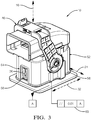
- Fig. 3 illustrates the assembly 10 in a seated-position 58.
- the gear-teeth 48 engage the gear-racks 20 of the first-housing 12 and move the second-housing 28 from the prestage-position 50 to the seated-position 58.
- the flex-locks 56 move beyond the second-angles 40 of the first-fins 34 and ultimately engage the second-angles 40 of the second-fins 36, thereby inhibiting a movement between the second-housing 28 and the first-housing 12.
- a parallelism 60 between the first-housing 12 and the second-housing 28 relative to a plane parallel with the longitudinal-axis 32 is less than 0.01-mm when the flex-locks 56 engage the second-fins 36.
- the parallelism 60 has the technical benefit of maintaining a proper alignment between the electrical-terminals 18 and the corresponding electrical-terminals 42 for electrical circuit continuity, as well as maintaining the proper alignment between the first-housing 12 and the second-housing 28 for optimum sealing of the assembly 10.
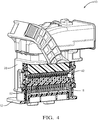
- Fig. 4 is a cut-away perspective view of the assembly 10 in the prestage-position 50 illustrating internal components of the assembly 10.
- the second-housing 28 further includes an inner-housing-assembly 62 that retains the corresponding electrical-terminals 42.
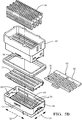
- Figs. 5A-5B illustrate the inner-housing-assembly 62 isolated from the assembly 10.
- the inner-housing-assembly 62 includes a base 64 configured to retain connector-ends (not specifically shown) of a plurality of the corresponding electrical-terminals 42 housed within the assembly 10.
- a center-to-center spacing between the adjacent corresponding electrical-terminals 42 is about 2.2 mm, or less, to increase a terminal-density of the assembly 10. This spacing is a unique characteristic of the inner-housing-assembly 62 that is enabled by the structure, and would not otherwise be viably manufactured in a single-molded part.
- the base 64 includes second-walls 66 extending along the mating-axis 16 of the assembly 10 that define a first-slot 68 and a second-slot 70 opposite the first-slot 68.
- the first-slot 68 and the second-slot 70 extend along the longitudinal-axis 32 of the assembly 10, and the first-slot 68 has a length greater than the second-slot 70, the reason for which will be explained in more detail below.
- the inner-housing-assembly 62 also includes a terminal-lock 72 overlaying the base 64 configured to releasably lock the plurality of corresponding electrical-terminals 42 within the base 64.
- the terminal-lock 72 includes a plurality of cantilevered locking-arms 74 (hereafter the locking-arms 74) configured to releasably lock the plurality of corresponding electrical-terminals 42 within the base 64.
- Fig. 6 illustrates the terminal-lock 72 isolated from the inner-housing-assembly 62 and rotated 180-degrees to reveal the locking-arms 74 that are disposed within terminal-cavities 76 defined by the base 64.
- the locking-arms 74 are configured to extend along the mating-axis 16 into the terminal-cavities 76, and are adjacent to electrical-isolation-walls 78.
- the electrical-isolation-walls 78 inhibit an overtravel of the locking-arms 74 and further increase an electrical-isolation between the plurality of corresponding electrical-terminals 42.
- the electrical-isolation-walls 78 are supported by a plurality of buttresses 80 extending along the mating-axis 16 that are formed integral to the electrical-isolation-walls 78.
- the buttresses 80 are configured to increase a stiffness of the electrical-isolation-walls 78 to resist the overtravel of the locking-arms 74.
- the inner-housing-assembly 62 also includes a crimp-housing 82 configured to retain crimp-ends (not specifically shown) of the plurality of corresponding electrical-terminals 42 within crimp-cavities (not specifically shown) defined by the crimp-housing 82.
- the crimp-housing 82 overlays the terminal-lock 72 and is retained by a plurality of locking-fingers 84 extending inward from the second-walls 66 of the base 64.
- the plurality of locking-fingers 84 inhibit an unintentional disassembly of the inner-housing-assembly 62.
- Fig. 7 is a section view of a portion of the inner-housing-assembly 62 with the plurality of corresponding electrical-terminals 42 removed.
- the crimp-housing 82 defines a passage 86 extending along both the lateral-axis 24 and the longitudinal-axis 32, and is disposed between the first-slot 68 and the second-slot 70 of the base 64.
- An intermediate-secondary-lock 88 (ISL 88) is slideably disposed within the passage 86.
- the ISL 88 is moveable from a first-position 90 (see Fig. 8A ) to a second-position 92 (see Fig.
- the ISL 88 has a leading-edge 94 and a trailing-edge 96 opposite the leading-edge 94.
- a plurality of pressure-pads 98 on the leading-edge 94 of the ISL 88 create a transition-fit when the ISL 88 is moved to the second-position 92, thereby inhibiting the movement between the base 64, the terminal-lock 72, and the crimp-housing 82. That is, the pressure-pads 98 create a wedge between the components of the inner-housing-assembly 62 and inhibit movement that may be caused by vibrations.
- Figs. 8A-8B are section views of the inner-housing-assembly 62 inverted and viewed from the opposite side relative to Fig. 7 , and include the plurality of corresponding electrical-terminals 42.
- Figs. 8A-8B illustrate the movement of the ISL 88 from the first-position 90 to the second-position 92.
- the trailing-edge 96 of the ISL 88 is disposed within the first-slot 68, however the leading-edge 94 of the ISL 88 is not disposed within the second-slot 70.
- the ISL 88 is moved to the second-position 92 ( Fig. 8B )
- a portion of the leading-edge 94 is disposed within the second-slot 70, thereby interlocking the base 64 with the crimp-housing 82 at both the first-slot 68 and the second-slot 70.
- Figs. 9A-9B illustrate the ISL 88 isolated from the inner-housing-assembly 62 from two perspectives and show the pressure-pads 98.
- the pressure-pads 98 are located on the leading-edge 94 of the ISL 88. In another embodiment, the pressure-pads 98 are distributed across the ISL 88.
- first contact could be termed a second contact
- second contact could be termed a first contact
- the first contact and the second contact are both contacts, but they are not the same contact.
- the terminology used in the description of the various described embodiments herein is for the purpose of describing particular embodiments only and is not intended to be limiting. As used in the description of the various described embodiments and the appended claims, the singular forms "a”, “an” and “the” are intended to include the plural forms as well, unless the context clearly indicates otherwise. It will also be understood that the term “and/or” as used herein refers to and encompasses any and all possible combinations of one or more of the associated listed items.
- the phrase “if it is determined” or “if [a stated condition or event] is detected” is, optionally, construed to mean “upon determining” or “in response to determining” or “upon detecting [the stated condition or event]” or “in response to detecting [the stated condition or event],” depending on the context.
- Directional terms such as top, bottom, upper, lower, left, right, front, rear, etc. do not denote any particular orientation, but rather these directional terms are used to distinguish one element from another and establish a relationship between the various elements.
Landscapes
- Details Of Connecting Devices For Male And Female Coupling (AREA)
- Connector Housings Or Holding Contact Members (AREA)
Description
- This disclosure generally relates to an electrical connector, and more particularly relates to an electrical connector with a high vibration resistant locking mechanism.
- Publication
EP 3 142 194 A1 discloses a connector assembly comprising a first connector having a first housing and an intermediate housing attached to the first housing. The intermediate housing is moveable from a first position to a second position. A flexible retaining arm is configured to hold the intermediate housing in the first position. The connector assembly further includes a second connector having a second housing. The second housing defines a release wedge that engages and flexes the retaining arm, thereby releasing the intermediate housing from engagement with the retaining arm and allowing the intermediate housing to move from the first position to the second position as the first connector is connected to the second connector. A terminal in the first housing is enclosed within the intermediate housing in the first position, and protrudes from an aperture in a surface of the intermediate housing in the second position. PublicationEP 2 889 966 A1 discloses a lever-actuated connector having a wire cover to which a lever is attached so as to be rotatable between an initial mating position and a final mating position, and a housing to which the wire cover is mounted. An interference structure is provided between the lever and the housing, the interference structure arranged to prevent the wire cover, having the lever placed in a position for mounting the wire cover to the housing, from being mounted to the housing with an improper orientation. PublicationWO 2012/011604 A1 discloses a lever type connector including a connector housing to be engaged with a mating connecter housing, a spacer, a lever including a cam groove and turnably attached to the connector housing, a terminal to be inserted into a rear end surface of the connector housing, a positioning lock provided in the lever to temporarily fix the lever to be attached to the connector housing, a jig passing space formed in the positioning lock, and a spacer pushing surface provided on an upper side of the spacer. The spacer pushing surface is formed in symmetrical position to the jig passing space. The spacer pushing surfaces are pushed by pushing pins which are provided on the jig in bilaterally symmetrical positions with respect to a center line that intersects orthogonally with the longitudinal direction of the spacer. - An electrical connector-assembly according to the invention is disclosed in claim 1. Other aspects of the invention are disclosed in the dependent claims.
- The present invention will now be described, by way of example with reference to the accompanying drawings, in which:
-
Fig. 1A is an exploded perspective view of an illustration of an electrical-connector assembly in accordance with the invention; -
Fig. 1B is a close-up view of a portion of the electrical-connector assembly ofFig. 1A in accordance with the invention; -
Fig. 2 is an illustration of the electrical-connector assembly ofFig. 1 in a prestage-position in accordance with the invention; -
Fig. 3 is an illustration of the electrical-connector assembly ofFig. 1 in a seated-position in accordance with the invention; -
Fig. 4 is a section view of the electrical-connector assembly ofFig. 2 in accordance with the invention; -
Fig. 5A is an illustration of an inner-housing-assembly isolated from the electrical-connector assembly ofFig. 1 in accordance with the invention; -
Fig. 5B is an exploded view of the inner-housing-assembly ofFig. 5A in accordance with the invention; -
Fig. 6 is an illustration of a terminal-lock 72 isolated from the inner-housing-assembly ofFig. 5B in accordance with the invention; -
Fig. 7 is a section view of a portion of the of the inner-housing-assembly ofFig. 5A in accordance with the invention; -
Fig. 8A is another section view of the inner-housing-assembly ofFig. 5A in accordance with the invention; -
Fig. 8B is yet another section view of the inner-housing-assembly ofFig. 5A in accordance with the invention; and -
Fig. 9A is an illustration of an intermediate-secondary-lock isolated from the inner-housing-assembly ofFig. 5B in accordance with the invention. - Reference will now be made in detail to embodiments, examples of which are illustrated in the accompanying drawings. In the following detailed description, numerous specific details are set forth in order to provide a thorough understanding of the various described embodiments. However, it will be apparent to one of ordinary skill in the art that the various described embodiments may be practiced without these specific details. In other instances, well-known methods, procedures, components, circuits, and networks have not been described in detail so as not to unnecessarily obscure aspects of the embodiments.
-
Fig. 1A is a perspective exploded view illustrating an electrical connector-assembly 10, hereafter referred to as theassembly 10. As will be described in more detail below, theassembly 10 is an improvement over other connector assemblies, because theassembly 10 resists high vibrations by limiting a movement between connector housings. - The
assembly 10 includes a first-housing 12 that has first-walls 14 aligned parallel to a mating-axis 16 of theassembly 10. The first-housing 12 is formed of a polymeric dielectric material. The polymeric dielectric material may be any polymeric dielectric material capable of electrically isolating portions of electrical-terminals 18 (seeFig. 4 ) retained by the first-housing 12, and is preferably a polyamide (NYLON) material. The first-walls 14 include opposed gear-racks 20 extending beyond an outer-surface 22 of the first-walls 14 along a lateral-axis 24 and aligned with the mating-axis 16. The opposed gear-racks 20 are configured to engage a mate-assist device 26 mounted on a second-housing 28, as will be described in more detail below. - The first-
walls 14 include opposed locking-fins 30, hereafter referred to as the locking-fins 30, extending along a longitudinal-axis 32 beyond the outer-surface 22 and are aligned with the mating-axis 16. The locking-fins 30 have first-fins 34 and second-fins 36 aligned with the mating-axis 16, with the first-fin 34 positioned superior to (i.e. above, distal to, etc.) the second-fin 36, as illustrated inFigs. 1A-1B . In one embodiment the first-housing 12 includes a single pair of opposed first-fin 34 and second-fin 36 pairs. In the example illustrated inFig. 1 , the first-housing 12 further includes a plurality of opposed first-fin 34 and second-fin 36 pairs that are located on opposite sides of the first-housing 12 from one another. The first-fins 34 and the second-fins 36 define first-angles 38 and second-angles 40 (seeFig. 1B ), with the first-angles 38 less than the second-angles 40, the function of which will be described in more detail below. Preferably, the first-angles 38 are in a range between 15-degrees and 30-degrees, and the second-angles 40 are in the range between 30-degrees and 60-degrees. - The
assembly 10 also includes the second-housing 28 configured to retain corresponding electrical-terminals 42 that are configured to mate with the electrical-terminals 18 of the first-housing 12 (seeFig. 4 ). The second-housing 28 is preferably formed of the same polymeric dielectric material as the first-housing 12, but may be any polymeric dielectric material. The second-housing 28 includes the mate-assist device 26 which is moveable from an unlocked-position 44 to a locked-position 46 (seeFig. 3 ). In the example illustrated inFig. 1 , the mate-assist device 26 is in the unlocked-position 44. The mate-assist device 26 is pivotable about the lateral-axis 24 and includes gear-teeth 48 configured to engage the opposed gear-racks 20 of the first-housing 12. The mate-assist device 26 reversibly locks in the locked-position 46 to a locking-lug extending from a wire dress cover (not specifically shown) that forms the top of the second-housing 28. -
Fig. 2 illustrates theassembly 10 in a prestage-position 50. The second-housing 28 has askirt 52 aligned with (i.e. parallel to) the mating-axis 16. Theskirt 52 is configured to slideably engage the outer-surface 22 of the first-housing 12 when the second-housing 28 is mated with the first-housing 12. Theskirt 52 defines opposed-apertures 54 aligned with the longitudinal-axis 32 into which are disposed flex-locks 56 that extend along the mating-axis 16. The flex-locks 56 are configured to engage the first-fins 34 on the first-housing 12 and retain the second-housing 28 in the prestage-position 50. That is, the flex-locks 56 slide along the first-angles 38 of the first-fins 34 and engage the greater inclined second-angles 40 of the first-fins 34 when theassembly 10 is placed in the prestage-position 50. The flex-locks 56 are configured to resist a rotational-moment of the second-housing 28 about the lateral-axis 24 that may be caused by a weight of wire-cables (e.g., a wiring-harness - not shown) exiting the wire dress cover. In the examples illustrated inFigs. 1A and2 , theskirt 52 includes a plurality of corresponding flex-locks 56 that engage the plurality of opposed first-fin 34 and second-fin 36 pairs that are located on opposite sides of the first-housing 12. A force of between about 10-Newtons and about 15-Newtons is required to remove the second-housing 28 from the first-housing 12 when the second-housing 28 is in the prestage-position 50. Experimentation by the inventors has discovered that the force in this range is sufficient to resist an equivalent rotational-force applied by a 1-meter length of wiring-harness. This has the technical benefit of maintaining the second-housing 28 in the prestage-position 50 during an installation of the wiring-harness and inhibiting an unintentional removal, while meeting ergonomic requirements for an intentional removal by an assembler. -
Fig. 3 illustrates theassembly 10 in a seated-position 58. When the mate-assist device 26 is moved from the unlocked-position 44 to the locked-position 46, the gear-teeth 48 engage the gear-racks 20 of the first-housing 12 and move the second-housing 28 from the prestage-position 50 to the seated-position 58. The flex-locks 56 move beyond the second-angles 40 of the first-fins 34 and ultimately engage the second-angles 40 of the second-fins 36, thereby inhibiting a movement between the second-housing 28 and the first-housing 12. In the seated-position 58 aparallelism 60 between the first-housing 12 and the second-housing 28 relative to a plane parallel with the longitudinal-axis 32 (denoted by Datum "A" inFig. 3 ) is less than 0.01-mm when the flex-locks 56 engage the second-fins 36. Theparallelism 60 has the technical benefit of maintaining a proper alignment between the electrical-terminals 18 and the corresponding electrical-terminals 42 for electrical circuit continuity, as well as maintaining the proper alignment between the first-housing 12 and the second-housing 28 for optimum sealing of theassembly 10. -
Fig. 4 is a cut-away perspective view of theassembly 10 in the prestage-position 50 illustrating internal components of theassembly 10. The second-housing 28 further includes an inner-housing-assembly 62 that retains the corresponding electrical-terminals 42. -
Figs. 5A-5B illustrate the inner-housing-assembly 62 isolated from theassembly 10. The inner-housing-assembly 62 includes a base 64 configured to retain connector-ends (not specifically shown) of a plurality of the corresponding electrical-terminals 42 housed within theassembly 10. Preferably, a center-to-center spacing between the adjacent corresponding electrical-terminals 42 is about 2.2 mm, or less, to increase a terminal-density of theassembly 10. This spacing is a unique characteristic of the inner-housing-assembly 62 that is enabled by the structure, and would not otherwise be viably manufactured in a single-molded part. Thebase 64 includes second-walls 66 extending along the mating-axis 16 of theassembly 10 that define a first-slot 68 and a second-slot 70 opposite the first-slot 68. The first-slot 68 and the second-slot 70 extend along the longitudinal-axis 32 of theassembly 10, and the first-slot 68 has a length greater than the second-slot 70, the reason for which will be explained in more detail below. - Referring to
Fig. 5B , the inner-housing-assembly 62 also includes a terminal-lock 72 overlaying the base 64 configured to releasably lock the plurality of corresponding electrical-terminals 42 within thebase 64. The terminal-lock 72 includes a plurality of cantilevered locking-arms 74 (hereafter the locking-arms 74) configured to releasably lock the plurality of corresponding electrical-terminals 42 within thebase 64. -
Fig. 6 illustrates the terminal-lock 72 isolated from the inner-housing-assembly 62 and rotated 180-degrees to reveal the locking-arms 74 that are disposed within terminal-cavities 76 defined by thebase 64. The locking-arms 74 are configured to extend along the mating-axis 16 into the terminal-cavities 76, and are adjacent to electrical-isolation-walls 78. The electrical-isolation-walls 78 inhibit an overtravel of the locking-arms 74 and further increase an electrical-isolation between the plurality of corresponding electrical-terminals 42. The electrical-isolation-walls 78 are supported by a plurality ofbuttresses 80 extending along the mating-axis 16 that are formed integral to the electrical-isolation-walls 78. Thebuttresses 80 are configured to increase a stiffness of the electrical-isolation-walls 78 to resist the overtravel of the locking-arms 74. - Referring back to
Fig. 5B , the inner-housing-assembly 62 also includes a crimp-housing 82 configured to retain crimp-ends (not specifically shown) of the plurality of corresponding electrical-terminals 42 within crimp-cavities (not specifically shown) defined by the crimp-housing 82. The crimp-housing 82 overlays the terminal-lock 72 and is retained by a plurality of locking-fingers 84 extending inward from the second-walls 66 of thebase 64. The plurality of locking-fingers 84 inhibit an unintentional disassembly of the inner-housing-assembly 62. -
Fig. 7 is a section view of a portion of the inner-housing-assembly 62 with the plurality of corresponding electrical-terminals 42 removed. The crimp-housing 82 defines apassage 86 extending along both the lateral-axis 24 and the longitudinal-axis 32, and is disposed between the first-slot 68 and the second-slot 70 of thebase 64. An intermediate-secondary-lock 88 (ISL 88) is slideably disposed within thepassage 86. TheISL 88 is moveable from a first-position 90 (seeFig. 8A ) to a second-position 92 (seeFig. 8B ) along the lateral-axis 24, and is configured to inhibit the movement of the plurality of corresponding electrical-terminals 42 along the mating-axis 16 when moved to the second-position 92. It will be appreciated that when theISL 88 is in the first-position 90, an assembler is able to insert the plurality of corresponding electrical-terminals 42 into the terminal-cavities 76. TheISL 88 has a leading-edge 94 and a trailing-edge 96 opposite the leading-edge 94. A plurality of pressure-pads 98 on the leading-edge 94 of theISL 88 create a transition-fit when theISL 88 is moved to the second-position 92, thereby inhibiting the movement between the base 64, the terminal-lock 72, and the crimp-housing 82. That is, the pressure-pads 98 create a wedge between the components of the inner-housing-assembly 62 and inhibit movement that may be caused by vibrations. -
Figs. 8A-8B are section views of the inner-housing-assembly 62 inverted and viewed from the opposite side relative toFig. 7 , and include the plurality of corresponding electrical-terminals 42.Figs. 8A-8B illustrate the movement of theISL 88 from the first-position 90 to the second-position 92. When theISL 88 is in the first-position 90 (Fig. 8A ), the trailing-edge 96 of theISL 88 is disposed within the first-slot 68, however the leading-edge 94 of theISL 88 is not disposed within the second-slot 70. When theISL 88 is moved to the second-position 92 (Fig. 8B ), a portion of the leading-edge 94 is disposed within the second-slot 70, thereby interlocking the base 64 with the crimp-housing 82 at both the first-slot 68 and the second-slot 70. -
Figs. 9A-9B illustrate theISL 88 isolated from the inner-housing-assembly 62 from two perspectives and show the pressure-pads 98. In one embodiment, the pressure-pads 98 are located on the leading-edge 94 of theISL 88. In another embodiment, the pressure-pads 98 are distributed across theISL 88. - While this invention has been described in terms of the preferred embodiments thereof, it is not intended to be so limited, but rather only to the extent set forth in the claims that follow. "One or more" includes a function being performed by one element, a function being performed by more than one element, e.g., in a distributed fashion, several functions being performed by one element, several functions being performed by several elements, or any combination of the above. It will also be understood that, although the terms first, second, etc. are, in some instances, used herein to describe various elements, these elements should not be limited by these terms. These terms are only used to distinguish one element from another. For example, a first contact could be termed a second contact, and, similarly, a second contact could be termed a first contact, without departing from the scope of the various described embodiments. The first contact and the second contact are both contacts, but they are not the same contact. The terminology used in the description of the various described embodiments herein is for the purpose of describing particular embodiments only and is not intended to be limiting. As used in the description of the various described embodiments and the appended claims, the singular forms "a", "an" and "the" are intended to include the plural forms as well, unless the context clearly indicates otherwise. It will also be understood that the term "and/or" as used herein refers to and encompasses any and all possible combinations of one or more of the associated listed items. It will be further understood that the terms "includes," "including," "comprises," and/or "comprising," when used in this specification, specify the presence of stated features, integers, steps, operations, elements, and/or components, but do not preclude the presence or addition of one or more other features, integers, steps, operations, elements, components, and/or groups thereof. As used herein, the term "if' is, optionally, construed to mean "when" or "upon" or "in response to determining" or "in response to detecting," depending on the context. Similarly, the phrase "if it is determined" or "if [a stated condition or event] is detected" is, optionally, construed to mean "upon determining" or "in response to determining" or "upon detecting [the stated condition or event]" or "in response to detecting [the stated condition or event]," depending on the context. Directional terms such as top, bottom, upper, lower, left, right, front, rear, etc. do not denote any particular orientation, but rather these directional terms are used to distinguish one element from another and establish a relationship between the various elements.
Claims (7)
- An electrical connector assembly (10), said assembly (10) comprising:a first housing (12) having first walls (14) aligned parallel to a mating axis (16) of the assembly (10);
the first walls (14) including opposed locking fins (30) extending along a longitudinal axis (32) beyond an outer surface (22) of the first walls (14) and aligned with the mating axis (16);
the opposed locking fins (30) having first fins (34) and second fins (36) aligned with the mating axis (16);a second housing (28) comprising:
a mate assist device (26) which is moveable from an unlocked position (44) to a locked position (46);the mate assist device (26) pivotable about a lateral axis (24);the second housing (28) having a skirt (52) aligned with the mating axis (16);the skirt (52) configured to slideably engage the outer surface (22) of the first housing (12);the skirt (52) including flex locks (56) extending along the mating axis (16);
the flex locks (56) configured to engage the first fins (34) and retain the second housing (28) in a prestage position (50);wherein the second housing (28) further includes an inner housing assembly (62), said inner housing assembly (62) comprising:a base (64) configured to retain connector ends of a plurality of corresponding electrical terminals (18) housed within the assembly (10);characterized in that:the first walls (14) include opposed gear racks (20) extending beyond the outer surface (22) of the first walls (14) along the lateral axis (24) and aligned with the mating axis (16);the opposed gear racks (20) are configured to engage the mate assist device (26);the mate assist device (26) has gear teeth (48) configured to engage the opposed gear racks (20) of the first housing (12);the skirt (52) defines opposed apertures (54) aligned with the longitudinal axis (32);the flex locks (56) are disposed within the opposed apertures (54); andthe second housing (28) is moved from the prestage position (50) to a seated position (58) when the mate assist device (26) is moved from the unlocked position (44) to the locked position (46), whereby the flex locks (56) engage the second fins (36), thereby inhibiting a movement between the second housing (28) and the first housing (12),the base (64) includes second walls (66) extending along the mating axis (16) of the assembly (10), the second walls (66) defining a first slot (68) and a second slot (70) opposite the first slot (68), the first slot (68) and the second slot (70) extending along the longitudinal axis (32) of the assembly (10), wherein the first slot (68) has a length greater than the second slot (70);and said inner housing assembly (62) further comprises:a terminal lock (72) overlaying the base (64) configured to releasably lock the plurality of corresponding electrical terminals (18) within the base (64);a crimp housing (82) configured to retain crimp ends of the plurality of corresponding electrical terminals (18) within crimp cavities defined by the crimp housing (82), the crimp housing (82) overlaying the connector lock; the crimp housing (82) defining a passage (86) extending along boththe lateral axis (24) and the longitudinal axis (32);the passage (86) disposed between the first slot (68) and the second slot (70); andan intermediate secondary lock (88) slideably disposed within the passage (86);
the intermediate secondary lock (88) moveable from a first position (90) to a second position (92) along the lateral axis (24);the intermediate secondary lock (88) configured to inhibit the movement of the plurality of corresponding electrical terminals (18) along the mating axis (16) when moved to the second position (92);the intermediate secondary lock (88) having a leading edge (94) and a trailing edge (96) opposite the leading edge (94);wherein when the intermediate secondary lock (88) is moved to the second position (92), a portion of the leading edge (94) is disposed within the second slot (70), thereby interlocking the base (64) with the crimp housing (82) at both the first slot (68) and the second slot (70). - The assembly (10) in accordance with claim 1, wherein a force of between about 10 Newtons and about 15 Newtons is required to remove the second housing (28) from the first housing (12) when the second housing (28) is in the prestage position (50).
- The assembly (10) in accordance with any one of the claims 1 or 2, wherein the first housing (12) further includes a plurality of opposed first fin (34) and second fin (36) pairs and the second housing (28) further includes a plurality of corresponding flex locks (56).
- The assembly (10) in accordance with any one of the claims 1 to 3, wherein the first fins (34) and the second fins (36) define first angles (38) and second angles (40), the first angles (38) less than the second angles (40).
- The assembly (10) in accordance with claim 4, wherein the first angles (38) are in a range between 15 degrees and 30 degrees and the second angles (40) are in the range between 30 degrees and 60 degrees.
- The assembly (10) in accordance with any one of the claims 1 to 5, wherein a parallelism (60) between the first housing (12) and the second housing (28) relative to a plane parallel with the longitudinal axis (32) is less than 0.01 mm when the flex locks (56) engage the second fins (36).
- The assembly (10) in accordance with any one of the claims 1 to 6, wherein the first housing (12) is configured to retain electrical terminals (18) and the second housing (28) configured to retain corresponding electrical terminals (18) configured to mate with the electrical terminals (18) of the first housing (12).
Applications Claiming Priority (1)
| Application Number | Priority Date | Filing Date | Title |
|---|---|---|---|
| US16/174,359 US10566728B1 (en) | 2018-10-30 | 2018-10-30 | Electrical connector with high vibration resistant locks |
Publications (2)
| Publication Number | Publication Date |
|---|---|
| EP3657610A1 EP3657610A1 (en) | 2020-05-27 |
| EP3657610B1 true EP3657610B1 (en) | 2021-05-19 |
Family
ID=68382285
Family Applications (1)
| Application Number | Title | Priority Date | Filing Date |
|---|---|---|---|
| EP19205603.4A Active EP3657610B1 (en) | 2018-10-30 | 2019-10-28 | Electrical connector assembly |
Country Status (3)
| Country | Link |
|---|---|
| US (1) | US10566728B1 (en) |
| EP (1) | EP3657610B1 (en) |
| CN (1) | CN111129839B (en) |
Families Citing this family (7)
| Publication number | Priority date | Publication date | Assignee | Title |
|---|---|---|---|---|
| DE102017125860A1 (en) * | 2017-11-06 | 2019-05-09 | Harting Electric Gmbh & Co. Kg | Locking clip for a connector housing |
| US11283219B2 (en) * | 2018-09-23 | 2022-03-22 | Apple Inc. | Connectors with high retention force |
| CN112152013B (en) * | 2019-06-26 | 2022-04-08 | 莫列斯有限公司 | Electrical connector and electrical connector assembly |
| CN113851896A (en) * | 2020-06-28 | 2021-12-28 | 安费诺商用电子产品(成都)有限公司 | Electrical connector and method for fitting and unfitting the same |
| CN115911941B (en) * | 2021-08-25 | 2026-01-30 | 中航光电科技股份有限公司 | A connector unlocking protection device |
| US12126116B2 (en) * | 2022-07-01 | 2024-10-22 | Aptiv Technologies AG | Vehicle electrical distribution center with gear driven mating assist system |
| CN116154566B (en) * | 2022-09-07 | 2024-06-07 | 文依精密科技(上海)有限公司 | An electrical connector with delayed unlocking and secondary locking |
Family Cites Families (35)
| Publication number | Priority date | Publication date | Assignee | Title |
|---|---|---|---|---|
| US4376563A (en) * | 1981-03-20 | 1983-03-15 | General Motors Corporation | Electrical connector with mechanically assisted latch means |
| JPH06132049A (en) * | 1992-04-02 | 1994-05-13 | Orbital Engine Co Pty Ltd | Multiple-conductor terminal assembly |
| GB9508189D0 (en) * | 1995-04-21 | 1995-06-07 | Amp Gmbh | Connector with pivotable coupling lever |
| US5954546A (en) * | 1996-09-23 | 1999-09-21 | General Motors Corporation | Electrical connector |
| US6004158A (en) * | 1997-03-27 | 1999-12-21 | The Whitaker Corporation | Electrical connector with secondary locking plates |
| US5934926A (en) * | 1998-02-06 | 1999-08-10 | Packard Hughes Interconnect Company | Electrical connector system with pre-staged feature |
| US5928038A (en) * | 1998-04-24 | 1999-07-27 | Molex Incorporated | Electrical connector position assurance system |
| JP3672229B2 (en) * | 2000-02-23 | 2005-07-20 | 矢崎総業株式会社 | Holder removal prevention connector |
| JP3813836B2 (en) * | 2001-05-18 | 2006-08-23 | 矢崎総業株式会社 | Half-mating prevention connector |
| JP2003017174A (en) * | 2001-07-04 | 2003-01-17 | Yazaki Corp | Connector with holder |
| US6739889B1 (en) * | 2003-05-30 | 2004-05-25 | Delphi Technologies, Inc. | Electrical distribution center assembly |
| US7004769B1 (en) * | 2004-08-20 | 2006-02-28 | Molex Incorporated | Lever type electrical connector with slide members having dual latching and feedback functions |
| DE102004043469B4 (en) * | 2004-09-08 | 2007-07-26 | Siemens Ag | Mounting device with a mounted thereon switching device |
| JP4252603B2 (en) * | 2007-01-31 | 2009-04-08 | タイコエレクトロニクスアンプ株式会社 | Electrical connector |
| US7726988B2 (en) * | 2008-03-26 | 2010-06-01 | Tyco Electronics Corporation | Electrical connector having disconnection assist |
| JP5607446B2 (en) * | 2010-07-20 | 2014-10-15 | 矢崎総業株式会社 | connector |
| US8419485B2 (en) * | 2011-01-27 | 2013-04-16 | Tyco Electronics Corporation | Bulkhead connector assembly |
| JP5682476B2 (en) * | 2011-06-27 | 2015-03-11 | 住友電装株式会社 | connector |
| US8784127B2 (en) * | 2012-06-11 | 2014-07-22 | Delphi Technologies, Inc. | Electrical connection system including mating assist lever that contains locking means and connector position assurance member that interacts therewith |
| JP5846083B2 (en) * | 2012-09-06 | 2016-01-20 | 住友電装株式会社 | connector |
| JP5846105B2 (en) * | 2012-11-13 | 2016-01-20 | 住友電装株式会社 | Lever type connector |
| US9142916B2 (en) * | 2013-03-15 | 2015-09-22 | Tyco Electronics Corporation | Connector assembly with receptacle carriers |
| FR3005798B1 (en) * | 2013-05-17 | 2016-12-30 | Delphi Int Operations Luxembourg Sarl | CONNECTOR FOR MOTOR VEHICLES |
| EP2863489A1 (en) * | 2013-10-16 | 2015-04-22 | Delphi Technologies, Inc. | Connector assembly with integrated lever locking system |
| JP6036661B2 (en) * | 2013-11-19 | 2016-11-30 | 住友電装株式会社 | Waterproof connector |
| JP6381904B2 (en) * | 2013-12-24 | 2018-08-29 | タイコエレクトロニクスジャパン合同会社 | Lever type electrical connector |
| JP6252417B2 (en) * | 2014-09-19 | 2017-12-27 | 株式会社オートネットワーク技術研究所 | connector |
| US9666972B2 (en) * | 2014-11-13 | 2017-05-30 | Te Connectivity Corporation | Electrical connector |
| CN204441596U (en) * | 2015-03-26 | 2015-07-01 | 泰科电子(上海)有限公司 | Connector and connector assembly |
| CN204464633U (en) * | 2015-03-31 | 2015-07-08 | 泰科电子(上海)有限公司 | Connector and connector assembly |
| US9608357B1 (en) * | 2015-09-11 | 2017-03-28 | Delphi Technologies, Inc. | Right angle connector with terminal contact protection |
| JP6548038B2 (en) * | 2016-06-17 | 2019-07-24 | 住友電装株式会社 | connector |
| JP6755148B2 (en) * | 2016-08-30 | 2020-09-16 | タイコエレクトロニクスジャパン合同会社 | Lever type connector |
| CN206211108U (en) * | 2016-12-09 | 2017-05-31 | 泰科电子(上海)有限公司 | Latch fitting, connector |
| US9843126B1 (en) * | 2017-02-21 | 2017-12-12 | Sumitomo Wiring Systems, Ltd. | Connector housing assemblies with access hood and push surface |
-
2018
- 2018-10-30 US US16/174,359 patent/US10566728B1/en active Active
-
2019
- 2019-10-28 EP EP19205603.4A patent/EP3657610B1/en active Active
- 2019-10-29 CN CN201911036453.9A patent/CN111129839B/en active Active
Also Published As
| Publication number | Publication date |
|---|---|
| US10566728B1 (en) | 2020-02-18 |
| EP3657610A1 (en) | 2020-05-27 |
| CN111129839A (en) | 2020-05-08 |
| CN111129839B (en) | 2021-09-14 |
Similar Documents
| Publication | Publication Date | Title |
|---|---|---|
| US10566728B1 (en) | Electrical connector with high vibration resistant locks | |
| KR100933261B1 (en) | Connector, connector assembly and its connection method | |
| EP2235799B1 (en) | Electrical connector | |
| US9543683B2 (en) | Connector housing for an electric plug connector | |
| US20200251846A1 (en) | Electrical connector | |
| US9203186B2 (en) | Lever-type connector, wire cover | |
| EP0711005B1 (en) | Connector | |
| KR20100041767A (en) | Plug connector housing with a fixing for an electric contact element and a cable | |
| JP4162214B2 (en) | Electrical connector assembly | |
| JP2001332342A (en) | Lever connector | |
| JP4963702B2 (en) | Connector assembly having terminal position assurance device | |
| JP4985206B2 (en) | Connector and short terminal | |
| US20080242158A1 (en) | Connector | |
| EP1418649B1 (en) | A connector | |
| JP2020017523A (en) | Connector housing and terminal position assurance joint clip site | |
| EP0963009B1 (en) | A construction for preventing an error assembling of a connector housing and a cover and a connector comprising the same | |
| CN110945722B (en) | Connector | |
| JP4980342B2 (en) | Electrical connector with terminal position assurance mechanism | |
| KR20140093288A (en) | Lever type connector | |
| EP1973203B1 (en) | Electrical connector having lever with protective shroud | |
| US7210965B1 (en) | Cable connector assembly | |
| US20090221190A1 (en) | Electric connector housing | |
| JP6902209B2 (en) | Lever type connector | |
| JP4556134B2 (en) | connector | |
| WO2013175720A1 (en) | Connector |
Legal Events
| Date | Code | Title | Description |
|---|---|---|---|
| PUAI | Public reference made under article 153(3) epc to a published international application that has entered the european phase |
Free format text: ORIGINAL CODE: 0009012 |
|
| STAA | Information on the status of an ep patent application or granted ep patent |
Free format text: STATUS: THE APPLICATION HAS BEEN PUBLISHED |
|
| AK | Designated contracting states |
Kind code of ref document: A1 Designated state(s): AL AT BE BG CH CY CZ DE DK EE ES FI FR GB GR HR HU IE IS IT LI LT LU LV MC MK MT NL NO PL PT RO RS SE SI SK SM TR |
|
| AX | Request for extension of the european patent |
Extension state: BA ME |
|
| STAA | Information on the status of an ep patent application or granted ep patent |
Free format text: STATUS: REQUEST FOR EXAMINATION WAS MADE |
|
| 17P | Request for examination filed |
Effective date: 20201102 |
|
| RBV | Designated contracting states (corrected) |
Designated state(s): AL AT BE BG CH CY CZ DE DK EE ES FI FR GB GR HR HU IE IS IT LI LT LU LV MC MK MT NL NO PL PT RO RS SE SI SK SM TR |
|
| GRAP | Despatch of communication of intention to grant a patent |
Free format text: ORIGINAL CODE: EPIDOSNIGR1 |
|
| STAA | Information on the status of an ep patent application or granted ep patent |
Free format text: STATUS: GRANT OF PATENT IS INTENDED |
|
| GRAJ | Information related to disapproval of communication of intention to grant by the applicant or resumption of examination proceedings by the epo deleted |
Free format text: ORIGINAL CODE: EPIDOSDIGR1 |
|
| STAA | Information on the status of an ep patent application or granted ep patent |
Free format text: STATUS: REQUEST FOR EXAMINATION WAS MADE |
|
| INTG | Intention to grant announced |
Effective date: 20210212 |
|
| GRAS | Grant fee paid |
Free format text: ORIGINAL CODE: EPIDOSNIGR3 |
|
| STAA | Information on the status of an ep patent application or granted ep patent |
Free format text: STATUS: GRANT OF PATENT IS INTENDED |
|
| GRAP | Despatch of communication of intention to grant a patent |
Free format text: ORIGINAL CODE: EPIDOSNIGR1 |
|
| INTC | Intention to grant announced (deleted) | ||
| GRAA | (expected) grant |
Free format text: ORIGINAL CODE: 0009210 |
|
| STAA | Information on the status of an ep patent application or granted ep patent |
Free format text: STATUS: THE PATENT HAS BEEN GRANTED |
|
| INTG | Intention to grant announced |
Effective date: 20210323 |
|
| AK | Designated contracting states |
Kind code of ref document: B1 Designated state(s): AL AT BE BG CH CY CZ DE DK EE ES FI FR GB GR HR HU IE IS IT LI LT LU LV MC MK MT NL NO PL PT RO RS SE SI SK SM TR |
|
| REG | Reference to a national code |
Ref country code: GB Ref legal event code: FG4D |
|
| REG | Reference to a national code |
Ref country code: CH Ref legal event code: EP |
|
| REG | Reference to a national code |
Ref country code: DE Ref legal event code: R096 Ref document number: 602019004723 Country of ref document: DE |
|
| REG | Reference to a national code |
Ref country code: AT Ref legal event code: REF Ref document number: 1394897 Country of ref document: AT Kind code of ref document: T Effective date: 20210615 |
|
| REG | Reference to a national code |
Ref country code: IE Ref legal event code: FG4D |
|
| REG | Reference to a national code |
Ref country code: LT Ref legal event code: MG9D |
|
| REG | Reference to a national code |
Ref country code: AT Ref legal event code: MK05 Ref document number: 1394897 Country of ref document: AT Kind code of ref document: T Effective date: 20210519 |
|
| REG | Reference to a national code |
Ref country code: NL Ref legal event code: MP Effective date: 20210519 |
|
| PG25 | Lapsed in a contracting state [announced via postgrant information from national office to epo] |
Ref country code: BG Free format text: LAPSE BECAUSE OF FAILURE TO SUBMIT A TRANSLATION OF THE DESCRIPTION OR TO PAY THE FEE WITHIN THE PRESCRIBED TIME-LIMIT Effective date: 20210819 Ref country code: AT Free format text: LAPSE BECAUSE OF FAILURE TO SUBMIT A TRANSLATION OF THE DESCRIPTION OR TO PAY THE FEE WITHIN THE PRESCRIBED TIME-LIMIT Effective date: 20210519 Ref country code: LT Free format text: LAPSE BECAUSE OF FAILURE TO SUBMIT A TRANSLATION OF THE DESCRIPTION OR TO PAY THE FEE WITHIN THE PRESCRIBED TIME-LIMIT Effective date: 20210519 Ref country code: HR Free format text: LAPSE BECAUSE OF FAILURE TO SUBMIT A TRANSLATION OF THE DESCRIPTION OR TO PAY THE FEE WITHIN THE PRESCRIBED TIME-LIMIT Effective date: 20210519 Ref country code: FI Free format text: LAPSE BECAUSE OF FAILURE TO SUBMIT A TRANSLATION OF THE DESCRIPTION OR TO PAY THE FEE WITHIN THE PRESCRIBED TIME-LIMIT Effective date: 20210519 |
|
| PG25 | Lapsed in a contracting state [announced via postgrant information from national office to epo] |
Ref country code: GR Free format text: LAPSE BECAUSE OF FAILURE TO SUBMIT A TRANSLATION OF THE DESCRIPTION OR TO PAY THE FEE WITHIN THE PRESCRIBED TIME-LIMIT Effective date: 20210820 Ref country code: IS Free format text: LAPSE BECAUSE OF FAILURE TO SUBMIT A TRANSLATION OF THE DESCRIPTION OR TO PAY THE FEE WITHIN THE PRESCRIBED TIME-LIMIT Effective date: 20210919 Ref country code: NO Free format text: LAPSE BECAUSE OF FAILURE TO SUBMIT A TRANSLATION OF THE DESCRIPTION OR TO PAY THE FEE WITHIN THE PRESCRIBED TIME-LIMIT Effective date: 20210819 Ref country code: PL Free format text: LAPSE BECAUSE OF FAILURE TO SUBMIT A TRANSLATION OF THE DESCRIPTION OR TO PAY THE FEE WITHIN THE PRESCRIBED TIME-LIMIT Effective date: 20210519 Ref country code: LV Free format text: LAPSE BECAUSE OF FAILURE TO SUBMIT A TRANSLATION OF THE DESCRIPTION OR TO PAY THE FEE WITHIN THE PRESCRIBED TIME-LIMIT Effective date: 20210519 Ref country code: SE Free format text: LAPSE BECAUSE OF FAILURE TO SUBMIT A TRANSLATION OF THE DESCRIPTION OR TO PAY THE FEE WITHIN THE PRESCRIBED TIME-LIMIT Effective date: 20210519 Ref country code: PT Free format text: LAPSE BECAUSE OF FAILURE TO SUBMIT A TRANSLATION OF THE DESCRIPTION OR TO PAY THE FEE WITHIN THE PRESCRIBED TIME-LIMIT Effective date: 20210920 Ref country code: RS Free format text: LAPSE BECAUSE OF FAILURE TO SUBMIT A TRANSLATION OF THE DESCRIPTION OR TO PAY THE FEE WITHIN THE PRESCRIBED TIME-LIMIT Effective date: 20210519 |
|
| PG25 | Lapsed in a contracting state [announced via postgrant information from national office to epo] |
Ref country code: NL Free format text: LAPSE BECAUSE OF FAILURE TO SUBMIT A TRANSLATION OF THE DESCRIPTION OR TO PAY THE FEE WITHIN THE PRESCRIBED TIME-LIMIT Effective date: 20210519 |
|
| PG25 | Lapsed in a contracting state [announced via postgrant information from national office to epo] |
Ref country code: ES Free format text: LAPSE BECAUSE OF FAILURE TO SUBMIT A TRANSLATION OF THE DESCRIPTION OR TO PAY THE FEE WITHIN THE PRESCRIBED TIME-LIMIT Effective date: 20210519 Ref country code: EE Free format text: LAPSE BECAUSE OF FAILURE TO SUBMIT A TRANSLATION OF THE DESCRIPTION OR TO PAY THE FEE WITHIN THE PRESCRIBED TIME-LIMIT Effective date: 20210519 Ref country code: SK Free format text: LAPSE BECAUSE OF FAILURE TO SUBMIT A TRANSLATION OF THE DESCRIPTION OR TO PAY THE FEE WITHIN THE PRESCRIBED TIME-LIMIT Effective date: 20210519 Ref country code: CZ Free format text: LAPSE BECAUSE OF FAILURE TO SUBMIT A TRANSLATION OF THE DESCRIPTION OR TO PAY THE FEE WITHIN THE PRESCRIBED TIME-LIMIT Effective date: 20210519 Ref country code: DK Free format text: LAPSE BECAUSE OF FAILURE TO SUBMIT A TRANSLATION OF THE DESCRIPTION OR TO PAY THE FEE WITHIN THE PRESCRIBED TIME-LIMIT Effective date: 20210519 Ref country code: RO Free format text: LAPSE BECAUSE OF FAILURE TO SUBMIT A TRANSLATION OF THE DESCRIPTION OR TO PAY THE FEE WITHIN THE PRESCRIBED TIME-LIMIT Effective date: 20210519 Ref country code: SM Free format text: LAPSE BECAUSE OF FAILURE TO SUBMIT A TRANSLATION OF THE DESCRIPTION OR TO PAY THE FEE WITHIN THE PRESCRIBED TIME-LIMIT Effective date: 20210519 |
|
| REG | Reference to a national code |
Ref country code: DE Ref legal event code: R097 Ref document number: 602019004723 Country of ref document: DE |
|
| PLBE | No opposition filed within time limit |
Free format text: ORIGINAL CODE: 0009261 |
|
| STAA | Information on the status of an ep patent application or granted ep patent |
Free format text: STATUS: NO OPPOSITION FILED WITHIN TIME LIMIT |
|
| 26N | No opposition filed |
Effective date: 20220222 |
|
| PG25 | Lapsed in a contracting state [announced via postgrant information from national office to epo] |
Ref country code: IS Free format text: LAPSE BECAUSE OF FAILURE TO SUBMIT A TRANSLATION OF THE DESCRIPTION OR TO PAY THE FEE WITHIN THE PRESCRIBED TIME-LIMIT Effective date: 20210919 Ref country code: AL Free format text: LAPSE BECAUSE OF FAILURE TO SUBMIT A TRANSLATION OF THE DESCRIPTION OR TO PAY THE FEE WITHIN THE PRESCRIBED TIME-LIMIT Effective date: 20210519 |
|
| REG | Reference to a national code |
Ref country code: BE Ref legal event code: MM Effective date: 20211031 |
|
| PG25 | Lapsed in a contracting state [announced via postgrant information from national office to epo] |
Ref country code: MC Free format text: LAPSE BECAUSE OF FAILURE TO SUBMIT A TRANSLATION OF THE DESCRIPTION OR TO PAY THE FEE WITHIN THE PRESCRIBED TIME-LIMIT Effective date: 20210519 |
|
| PG25 | Lapsed in a contracting state [announced via postgrant information from national office to epo] |
Ref country code: LU Free format text: LAPSE BECAUSE OF NON-PAYMENT OF DUE FEES Effective date: 20211028 Ref country code: IT Free format text: LAPSE BECAUSE OF FAILURE TO SUBMIT A TRANSLATION OF THE DESCRIPTION OR TO PAY THE FEE WITHIN THE PRESCRIBED TIME-LIMIT Effective date: 20210519 Ref country code: BE Free format text: LAPSE BECAUSE OF NON-PAYMENT OF DUE FEES Effective date: 20211031 |
|
| PG25 | Lapsed in a contracting state [announced via postgrant information from national office to epo] |
Ref country code: IE Free format text: LAPSE BECAUSE OF NON-PAYMENT OF DUE FEES Effective date: 20211028 |
|
| REG | Reference to a national code |
Ref country code: CH Ref legal event code: PL |
|
| P01 | Opt-out of the competence of the unified patent court (upc) registered |
Effective date: 20230424 |
|
| PG25 | Lapsed in a contracting state [announced via postgrant information from national office to epo] |
Ref country code: CY Free format text: LAPSE BECAUSE OF FAILURE TO SUBMIT A TRANSLATION OF THE DESCRIPTION OR TO PAY THE FEE WITHIN THE PRESCRIBED TIME-LIMIT Effective date: 20210519 |
|
| PG25 | Lapsed in a contracting state [announced via postgrant information from national office to epo] |
Ref country code: LI Free format text: LAPSE BECAUSE OF NON-PAYMENT OF DUE FEES Effective date: 20221031 Ref country code: HU Free format text: LAPSE BECAUSE OF FAILURE TO SUBMIT A TRANSLATION OF THE DESCRIPTION OR TO PAY THE FEE WITHIN THE PRESCRIBED TIME-LIMIT; INVALID AB INITIO Effective date: 20191028 Ref country code: CH Free format text: LAPSE BECAUSE OF NON-PAYMENT OF DUE FEES Effective date: 20221031 |
|
| PG25 | Lapsed in a contracting state [announced via postgrant information from national office to epo] |
Ref country code: MK Free format text: LAPSE BECAUSE OF FAILURE TO SUBMIT A TRANSLATION OF THE DESCRIPTION OR TO PAY THE FEE WITHIN THE PRESCRIBED TIME-LIMIT Effective date: 20210519 |
|
| PG25 | Lapsed in a contracting state [announced via postgrant information from national office to epo] |
Ref country code: MT Free format text: LAPSE BECAUSE OF FAILURE TO SUBMIT A TRANSLATION OF THE DESCRIPTION OR TO PAY THE FEE WITHIN THE PRESCRIBED TIME-LIMIT Effective date: 20210519 |
|
| REG | Reference to a national code |
Ref country code: DE Ref legal event code: R081 Ref document number: 602019004723 Country of ref document: DE Owner name: APTIV TECHNOLOGIES AG, CH Free format text: FORMER OWNER: APTIV TECHNOLOGIES LIMITED, ST. MICHAEL, BB |
|
| PG25 | Lapsed in a contracting state [announced via postgrant information from national office to epo] |
Ref country code: TR Free format text: LAPSE BECAUSE OF FAILURE TO SUBMIT A TRANSLATION OF THE DESCRIPTION OR TO PAY THE FEE WITHIN THE PRESCRIBED TIME-LIMIT Effective date: 20210519 |
|
| PGFP | Annual fee paid to national office [announced via postgrant information from national office to epo] |
Ref country code: DE Payment date: 20250917 Year of fee payment: 7 |
|
| PGFP | Annual fee paid to national office [announced via postgrant information from national office to epo] |
Ref country code: GB Payment date: 20251015 Year of fee payment: 7 |
|
| PGFP | Annual fee paid to national office [announced via postgrant information from national office to epo] |
Ref country code: FR Payment date: 20251014 Year of fee payment: 7 |