EP3657450A1 - Paper money handling device - Google Patents
Paper money handling device Download PDFInfo
- Publication number
- EP3657450A1 EP3657450A1 EP17918676.2A EP17918676A EP3657450A1 EP 3657450 A1 EP3657450 A1 EP 3657450A1 EP 17918676 A EP17918676 A EP 17918676A EP 3657450 A1 EP3657450 A1 EP 3657450A1
- Authority
- EP
- European Patent Office
- Prior art keywords
- paper money
- cover
- bottom portion
- unit
- face
- Prior art date
- Legal status (The legal status is an assumption and is not a legal conclusion. Google has not performed a legal analysis and makes no representation as to the accuracy of the status listed.)
- Withdrawn
Links
- 238000009825 accumulation Methods 0.000 description 1
- 238000012986 modification Methods 0.000 description 1
- 230000004048 modification Effects 0.000 description 1
- 230000035699 permeability Effects 0.000 description 1
Images





Classifications
-
- G—PHYSICS
- G07—CHECKING-DEVICES
- G07D—HANDLING OF COINS OR VALUABLE PAPERS, e.g. TESTING, SORTING BY DENOMINATIONS, COUNTING, DISPENSING, CHANGING OR DEPOSITING
- G07D11/00—Devices accepting coins; Devices accepting, dispensing, sorting or counting valuable papers
- G07D11/40—Device architecture, e.g. modular construction
-
- G—PHYSICS
- G07—CHECKING-DEVICES
- G07D—HANDLING OF COINS OR VALUABLE PAPERS, e.g. TESTING, SORTING BY DENOMINATIONS, COUNTING, DISPENSING, CHANGING OR DEPOSITING
- G07D11/00—Devices accepting coins; Devices accepting, dispensing, sorting or counting valuable papers
- G07D11/10—Mechanical details
- G07D11/14—Inlet or outlet ports
-
- G—PHYSICS
- G07—CHECKING-DEVICES
- G07D—HANDLING OF COINS OR VALUABLE PAPERS, e.g. TESTING, SORTING BY DENOMINATIONS, COUNTING, DISPENSING, CHANGING OR DEPOSITING
- G07D11/00—Devices accepting coins; Devices accepting, dispensing, sorting or counting valuable papers
- G07D11/10—Mechanical details
- G07D11/16—Handling of valuable papers
- G07D11/18—Diverting into different paths or containers
-
- G—PHYSICS
- G07—CHECKING-DEVICES
- G07D—HANDLING OF COINS OR VALUABLE PAPERS, e.g. TESTING, SORTING BY DENOMINATIONS, COUNTING, DISPENSING, CHANGING OR DEPOSITING
- G07D2211/00—Paper-money handling devices
Definitions
- Paper money handling devices having cutouts for inserting fingers of a customer into a dispenser unit have been proposed in the past in order for the customer to easily pick up and take out paper money dispensed in the dispenser unit (see Patent Documents 1 to 3 for example).
- the present invention was made in view of the above point, and it is an object of the present invention to provide a paper money handling apparatus that enables a customer to easily take out paper money dispensed to a dispenser unit.
- a customer can easily take out paper money dispensed to the dispenser unit.
- FIG. 1 is a left side view of a paper money handling apparatus 1.
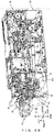
- FIG. 2A and FIG. 2B are perspective views illustrating an internal structure of a top module M1 and a take-in and recycle module M2 of the paper money handling apparatus 1.
- FIG. 1 to FIG. 2B a front-to-rear direction, a left-to-right direction, and an up-to-down direction are indicated in FIG. 1 to FIG. 2B , and also in FIG. 3A to FIG. 7 , which are described later.
- the paper money handling apparatus 1 includes a top module M1, a take-in and recycle module M2, recycle modules M3 and M4, a supplementary module M5, and a collection module M6 in this order from the top.
- the top module M1 has a deposit unit 20 for receiving paper money B when the paper money B is located at a deposit position P1 illustrated in FIG. 2A and a dispenser unit 10 for dispensing the paper money B when the paper money B is located at a dispense position P2 illustrated in FIG. 2B , both of which are provided in a front edge that is projected toward the front.
- the top module M1 has a carrier unit such as a dispensing carrier 50 that carries the paper money B to the dispenser unit 10 through a stage 40 on which a portion on the rear side of the paper money B is placed when the paper money B is located at the dispense position P2 and a discrimination unit that discriminates the paper money B.
- a take-in containment unit M2a and a take-in carrier 60 that carries paper money B into the take-in containment unit M2a are arranged.
- the take-in carrier 60 carries the remaining paper money B into the take-in containment unit M2a.
- the take-in and recycle module M2 has a gate 70 that moves between a block position to block a carrier path of paper money B to the take-in containment unit M2a when the paper money B is on the stage 40 and a retraction position to which the gate 70 is retracted from the block position.
- a pressing unit 80 that presses paper money B from above and holds the paper money B being carried by the take-in carrier 60 is arranged above the stage 40.
- the supplementary module M5 contains paper money B used for dispensing.
- the collection module M6 contains paper money B that is not recycled from among deposited paper money B.
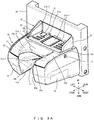
- FIG. 3A is a perspective view illustrating the dispenser unit 10 and the deposit unit 20 in a state in which a cover 15 is closed.
- FIG. 3B is a perspective view illustrating the dispenser unit 10 and the deposit unit 20 in a state in which the cover 15 is open.
- FIG. 4 is a top view illustrating the dispenser unit 10 and the deposit unit 20.
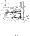
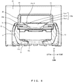
- FIG. 5 , FIG. 6 , and FIG. 7 are a cross-section at V-V in FIG. 4 , a cross-section at VI-VI, and a cross-section at VII-VII, respectively.
- the dispenser unit 10 has a bottom portion 11, a pair of side walls 12 and 13, a front wall 14, a cover 15, and rotary shaft units 16 and 17.
- the bottom portion 11, the pair of side walls 12 and 13, the front wall 14, and the cover 15 function as an accumulation unit that contains a portion on a front side of paper money B (see FIG. 2B ).
- the bottom portion 11, the pair of side walls 12 and 13, the front wall, and the rotary shaft units 16 and 17 are formed in an integrated manner with one another.
- cutouts 11a, 14a, and 15a are provided in the bottom portion 11, the front wall 14, and the cover 15 at the front edge of the dispenser unit 10.
- the cutouts 11a, 14a, and 15a are provided at the center of the bottom portion 11, the front wall 14, and the cover 15 in the left-to-right direction.
- the width of the cutouts 11a, 14a, and 15a in the left-to-right direction may be 2cm or longer as an example and may be formed to be shorter than the width of paper money B so that the paper money B can be picked up with fingers F from both over and under the paper money B as illustrated in FIG. 5 .
- the cutout 15a on the cover 15 is not necessarily provided, but only the cutouts 11a and 14a may be provided on the bottom portion 11 and the front wall 14.
- the height of the upper face 11b of the bottom portion 11, on the left and right sides of the cutout 11a becomes lower toward the cutout 11a.
- the height of the upper face 11b of the bottom portion 11, on the left and right sides of the cutout 11a becomes lower toward the front.
- the height of the upper face 11b of the bottom portion 11 becomes lower toward the rear.
- the upper face 11b of the bottom portion 11 has seven pieces, for example, of guide projections 11b-1 that slightly project upward, extend in the front-to-rear direction, and are arranged at intervals.
- the left side wall 12 is located at the left edge of the bottom portion 11 and the right side wall 13 is located at the right edge of the bottom portion 11.
- the front wall 11 is located at the front edge of the bottom portion 11.
- the cover 15 is located above the bottom portion 11. As illustrated in FIG. 3A and FIG. 4 to FIG. 7 , a rear face 15a-1 and left and right side faces 15a-2 and 15a-3 in a cutout 15a of the cover 15 are inclined or curved so that an opening space viewed from the top (see FIG. 4 ) becomes smaller toward the bottom. In addition, as illustrated in FIG. 5 , the cutout 11a of the bottom portion 11 is provided to extend further rearward than the lower edge of the cutout 15a of the cover 15.
- the rear face 15a-1 of the cutout 15a of the cover 15 is curved to sag downward in the center of the left-to-right direction so that the height of the center is lower than both the left and right sides toward the bottom.
- the rear face 15a-1 and one, not both, of the left and right side faces 15a-2 and 15a-3 of the cutout 15a of the cover 15 may be inclined or curved so that an opening space viewed from the top becomes smaller toward the bottom.
- the opening space viewed from the top may be the same regardless of the position in the up-to-down direction.
- the width of the lower edge of the cutout 15a of the cover 15 is slightly wider in the left-to-right direction than the cutout 11a of the bottom portion 11.
- the width of these portions may be the same or the width of the cutout 11a of the bottom portion 11 may be wider.
- the cutouts 15a and 11a are preferably formed so that when a foreign object such as a coin C falls down to or is placed on the upper face 15d of the cover 15, the foreign object falls down through the cutout 15a of the cover 15 and drops to the dispenser unit 10 via the cutout 11a of the bottom portion 11, as described above.
- the cover 15 has arm units 15b and 15c extending rearward from both left and right edges.
- the left arm unit 15b is integrated, for example, with the rotary shaft unit 16 projecting leftward.
- the right arm unit 15c is integrated, for example, with the rotary shaft unit 17 projecting rightward.
- the left rotary shaft unit 16 is rotatably inserted into the left side wall 12 and the right rotary shaft unit 17 is rotatably inserted into the right side wall 13.
- the cover 15 is arranged in an openable/closable manner so that the cover 15 rotates on the rotary shaft units 16 and 17 as a rotating center and opens from the front edge side.
- a customer can make the cover 15 rotate and open and can take out paper money B by picking up the paper money B with fingers F from over and under the paper money B located at the dispense position P2 and lifting up the front edge side of the cover 15 with the paper money B picked up with the fingers F.
- the deposit unit 20 receives paper money B from the deposit position P1 (see FIG. 2A ) above the dispense position P2 (see FIG. 2B ) of the paper money B in the dispenser unit 10. As illustrated in FIG. 3 to FIG. 5 , the deposit unit 20 has a bottom face guide 21.
- the upper face of the bottom face guide 21 is a guide face 21a that guides the bottom face of paper money B.
- the deposit unit 20 has side face guides 22 and 23 that guide the left and right side faces of the paper money B.
- the side face guides 22 and 23 are located at the left edge and the right edge of the bottom face guide 21.
- the side face guides 22 and 23 project toward the front from a frame member 30 for attaching the dispenser unit 10 and the deposit unit 20 to the top module M1 illustrated in FIG. 1 to FIG. 2B .
- the side face guides 22 and 23 are preferably integrated with the frame member 30.
- the dispenser unit 10 (or the deposit unit 20) is a separate portion from the deposit unit 20 (or the dispenser unit 10), the frame member 30, and the top module M1, the dispenser unit 10 (or the deposit unit 20) can be easily replaced with another one with a different shape in order to change a design of the paper money handling apparatus 1 or to accommodate various sizes of paper money B that are different for every countries.
- the cover 15, except for the arm units 15b and 15c, is located in the front of the bottom face guide 21.
- the upper face 15d of the cover 15 is formed so as to be continuous with the guide face 21a of the bottom face guide 21.
- the guide face 21a of the bottom face guide 21 is horizontal and the upper face 15d of the cover 15 is horizontal in a portion that is continuous with the front edge of the guide face 21a and is curved downward toward the front edge of the cover 15.
- the rear face 15a-1 of the cutout 15a of the cover 15 has an upper edge located at the same position as the front edge of the guide face 21a.
- the cutout 15a of the cover 15 may be provided in front of the front edge of the guide face 21a.
- the guide face 21 of the bottom face guide 21 has a lighting unit 21a-1 that is a lamp to inform a customer of the deposit position P1 of paper money B (see FIG. 2A ).
- This lighting unit 21a-1 is a rectangular portion that is located at the center of the guide face 21a in the left-to-right direction and covers almost throughout the guide face 21a in the front-to-rear direction and is also three linear portions extending in the left-to-right direction on each of the left and right sides of the rectangular portion.
- the guide face 21a also has six pieces, for example, of guide projections 21a-2 that slightly project upward, extend in the front-to-rear direction, and are arranged at intervals.
- a light emitter unit 21b that is an LED light source, for example, emitting light L1 toward the upper face 11b of the bottom portion 11 of the dispenser unit 10 is arranged in the bottom face guide 21.
- the light emitter unit 21b emits light L1, for example, to leave a customer of the dispense position P2 (see FIG. 2B ) of paper money B.
- the light L1 emitted by the light emitter unit 21b is reflected by the upper face 11b of the bottom portion 11 or the paper money B placed on the upper face 11b (reflected light L2).
- the reflected light L2 preferably passes at least through the rear face 15a-1 of the cutout 15a of the cover 15. For that reason, at least a portion of the cover 15 preferably has light permeability.
- the rear face 15a-1 in the cutout 15a of the cover 15 is inclined or curved so that an opening space viewed from the top becomes smaller toward the bottom, or in other words, is inclined or curved toward the front.
- This structure allows a customer to easily recognize the reflected light L2 as the rear face 15a-1 is lit by the reflected light L2.
- the rear face 15a-1 of the cutout 15a of the cover 15 is curved to sag downward in the center of the left-to-right direction so that the height of the center is lower than both the left and right sides toward the bottom, the customer can easily recognize the reflected light L2 as the reflected light L2 is collected at the rear face 15a-1.
- the cover 15 a portion rearward of the cutout 15a
- a customer can more easily recognize the reflected light L2 than when the portion is transparent.
- the dispenser unit 10 may have a locking mechanism that locks the cover 15 in a closed state at times other than dispensing paper money B.
- a locking mechanism that locks the cover 15 in a closed state at times other than dispensing paper money B.
- the take-in carrier 60 illustrated in FIG. 2A and FIG. 2B carries paper money B remaining in the dispenser unit 10
- the cover 15 is preferably locked in a closed state so that the paper money B in the dispenser unit 10 is not taken out by a customer or that a foreign object does not enter the dispenser unit 10.
- the paper money handling apparatus 1 is a paper money handling apparatus 1 provided with a dispenser unit 10 for dispensing paper money B, and the dispenser unit 10 has a bottom portion 11 on which at least a portion on the front side of the paper money B is placed, a pair of side walls 12 and 13 located at both lift and right edges of the bottom portion 11, a front wall 14 located at the front edge of the bottom portion 11, and a cover 15 located above the bottom portion 11.
- cutouts 11a and 14a are provided at least in the bottom portion 11 and the front wall 14, and the cover 15 is arranged in an openable/closable manner so that the cover 15 rotates and opens from the front edge side.
- the paper money B dispensed to the dispenser unit 10 is positioned by the bottom portion 11, the pair of side walls 12 and 13, the front wall 14, and the cover 15.
- This structure can prevent paper money B-1 from falling out toward the front, prevent curled paper money B-2 from popping up from the dispenser unit 10, and can also prevent jamming in the dispenser unit 10.
- dispensing paper money B at a desirable dispense position P2 can be more facilitated.
- the cutouts 11a and 14a provided at least in the bottom portion 11 and the front wall 14 allow a customer to easily pick up paper money B with fingers F and to easily take out the paper money B.
- a customer can easily take out paper money B dispensed to the dispenser unit 10.
- a foreign object such as a coin C illustrated in FIG. 3B can be guided toward the cutout 11a and drops to the dispenser unit 10 via the cutout 11a.
- the cutouts 11a, 14a, and 15a are provided in the bottom portion 11, the front wall 14, and the cover 15.
- a customer can insert fingers F into the cutouts 11a, 14a, and 15a from above the cover 15 and below the bottom portion 11, and thus the customer can easily pick up paper money B.
- a customer can more easily take out paper money B.
- At least one of the rear face 15a-1 and the side faces 15a-2 and 15a-3 in the cutout 15a of the cover 15 are inclined or curved so that an opening space viewed from the top becomes smaller toward the bottom.
- This structure can drop a foreign object such as a coin C to the dispenser unit 10 through the cutout 15a of the cover 15 and via the cutout 11a of the bottom portion 11.
- a customer can easily insert paper money B into the deposit unit 20.
- the paper money handling apparatus 1 further includes a deposit unit 20 to which paper money B is deposited from a deposit position P1 above a dispense position P2 of paper money B in the dispenser unit 10.
- the deposit unit 20 has a bottom face guide 21 including a guide face 21a that guides the bottom face of paper money B and the cover 15 except for arm units 15b and 15c (an example of at least a portion of the cover 15) is located in the front of the bottom face guide 21.
- the cover 15 can guide paper money B inserted into the deposit unit 20 with the upper face 15d or the cutout 15a, and thus a customer can easily insert paper money B into the deposit unit 20.
- the upper face 15d of the cover 15 is formed so as to be continuous with the guide face 21a of the bottom face guide 21. With this structure, the upper face 15d of the cover 15 can easily guide paper money B inserted into the deposit unit 20 and thus a customer can more easily insert paper money B into the deposit unit 20.
- the bottom face guide 21 further includes a light emitter unit 21b that emits light (light L1) to the upper face 11b of the bottom portion 11, and the cover 15 passes through light (reflected light L2) emitted by the light emitter unit 21b and reflected by the bottom portion 11 or the paper money B placed on the bottom portion 11.
- a customer can easily recognize the dispense position P2 of paper money B informed by the reflected light L2 from the light L1 emitted by the light emitter unit 21b.
- a customer can more easily take out paper money B.
Landscapes
- Physics & Mathematics (AREA)
- General Physics & Mathematics (AREA)
- Cash Registers Or Receiving Machines (AREA)
Abstract
Description
- The present invention relates to a paper money handling apparatus including a dispenser unit for dispensing paper money.
- Paper money handling devices having cutouts for inserting fingers of a customer into a dispenser unit have been proposed in the past in order for the customer to easily pick up and take out paper money dispensed in the dispenser unit (see
Patent Documents 1 to 3 for example). -
- Patent Document 1: Japanese Laid-Open Patent Publication No.
2010-267178 - Patent Document 2: Japanese Patent No.
5335877 - Patent Document 3: Japanese Patent No.
4849394 - Paper money dispensed to a dispenser unit, may not be accurately dispensed to a desirable dispense position particularly when the paper money is curled. In this case, when the paper money is not dispensed to the desirable dispense position, a customer may have difficulty in retrieving the paper money even when the above-described cutout is provided to the dispenser unit to help the customer pick up the paper money.
- The present invention was made in view of the above point, and it is an object of the present invention to provide a paper money handling apparatus that enables a customer to easily take out paper money dispensed to a dispenser unit.
- In one aspect, a paper money handling apparatus is a paper money handling apparatus including a dispenser unit to dispense paper money, and the dispenser unit includes a bottom portion on which at least a portion on a front side of the paper money is placed, a pair of side walls located at both the left and right sides of the bottom portion, a front wall located at a front edge of the bottom portion, and a cover located above the bottom portion. A front edge of the dispenser unit has cutouts at least in the bottom portion and the front wall, and the cover is arranged in an openable or closable manner so that the cover rotates and opens from a side of the front edge.
- According to the above aspect, a customer can easily take out paper money dispensed to the dispenser unit.
-
-
FIG. 1 is a left side view of a paper money handling apparatus; -
FIG. 2A is a perspective view (1) illustrating an internal structure of a top module and a take-in and recycle module; -
FIG. 2B is a perspective view (2) illustrating an internal structure of a top module and a take-in and recycle module; -
FIG. 3A is a perspective view illustrating a dispenser unit and a deposit unit in a state in which a cover is closed; -
FIG. 3B is a perspective view illustrating a dispenser unit and a deposit unit in a state in which a cover is open; -
FIG. 4 is a top view illustrating a dispenser unit and a deposit unit; -
FIG. 5 is a cross-section at V-V inFIG. 4 ; -
FIG. 6 is a cross-section at VI-VI inFIG. 4 ; and -
FIG. 7 is a cross-section at VII-VII inFIG. 4 . - In the following description, a paper money handling apparatus according to one of embodiments of the present invention is explained with reference to drawings.
-
FIG. 1 is a left side view of a papermoney handling apparatus 1. -
FIG. 2A andFIG. 2B are perspective views illustrating an internal structure of a top module M1 and a take-in and recycle module M2 of the papermoney handling apparatus 1. - Note that for convenience in explanation, a front-to-rear direction, a left-to-right direction, and an up-to-down direction are indicated in
FIG. 1 to FIG. 2B , and also inFIG. 3A to FIG. 7 , which are described later. This is merely an example, but the front-to-rear direction and the left-to-right direction are horizontal directions and the up-to-down direction is a vertical direction. - As illustrated in
FIG. 1 , the papermoney handling apparatus 1 includes a top module M1, a take-in and recycle module M2, recycle modules M3 and M4, a supplementary module M5, and a collection module M6 in this order from the top. - The top module M1 has a
deposit unit 20 for receiving paper money B when the paper money B is located at a deposit position P1 illustrated inFIG. 2A and adispenser unit 10 for dispensing the paper money B when the paper money B is located at a dispense position P2 illustrated inFIG. 2B , both of which are provided in a front edge that is projected toward the front. In addition, the top module M1 has a carrier unit such as a dispensingcarrier 50 that carries the paper money B to thedispenser unit 10 through astage 40 on which a portion on the rear side of the paper money B is placed when the paper money B is located at the dispense position P2 and a discrimination unit that discriminates the paper money B. - In the take-in and recycle module M2, a take-in containment unit M2a and a take-in
carrier 60 that carries paper money B into the take-in containment unit M2a are arranged. When a customer leaves paper money B dispensed to thedispenser unit 10, and this remaining paper money B is detected, the take-incarrier 60 carries the remaining paper money B into the take-in containment unit M2a. - Furthermore, as illustrated in
FIG. 2A , the take-in and recycle module M2 has agate 70 that moves between a block position to block a carrier path of paper money B to the take-in containment unit M2a when the paper money B is on thestage 40 and a retraction position to which thegate 70 is retracted from the block position. Moreover, as illustrated inFIG. 2B , apressing unit 80 that presses paper money B from above and holds the paper money B being carried by the take-incarrier 60 is arranged above thestage 40. - A recycle paper money containment unit, which is not illustrated, that contains paper money wrapped with a film, for example, is arranged in the rearward of the take-in containment unit M2a of the take-in and recycle module M2 and each of a front portion and a rear portion in each of the recycle modules M3 and M4.
- The supplementary module M5 contains paper money B used for dispensing. The collection module M6 contains paper money B that is not recycled from among deposited paper money B.
-
FIG. 3A is a perspective view illustrating thedispenser unit 10 and thedeposit unit 20 in a state in which acover 15 is closed.FIG. 3B is a perspective view illustrating thedispenser unit 10 and thedeposit unit 20 in a state in which thecover 15 is open. -
FIG. 4 is a top view illustrating thedispenser unit 10 and thedeposit unit 20. -
FIG. 5 ,FIG. 6 , andFIG. 7 are a cross-section at V-V inFIG. 4 , a cross-section at VI-VI, and a cross-section at VII-VII, respectively. - As illustrated in
FIG. 3A andFIG. 3B , thedispenser unit 10 has abottom portion 11, a pair ofside walls front wall 14, acover 15, androtary shaft units bottom portion 11, the pair ofside walls front wall 14, and thecover 15 function as an accumulation unit that contains a portion on a front side of paper money B (seeFIG. 2B ). Note that in thedispenser unit 10, thebottom portion 11, the pair ofside walls rotary shaft units - In the
bottom portion 11, thefront wall 14, and thecover 15 at the front edge of thedispenser unit 10,cutouts cutouts bottom portion 11, thefront wall 14, and thecover 15 in the left-to-right direction. - The width of the
cutouts FIG. 5 . Note that thecutout 15a on thecover 15 is not necessarily provided, but only thecutouts bottom portion 11 and thefront wall 14. - On the
bottom portion 11, at least a portion on the front side of the paper money B is placed. As illustrated inFIG. 3B andFIG. 6 , the height of theupper face 11b of thebottom portion 11, on the left and right sides of thecutout 11a, becomes lower toward thecutout 11a. For example on the left side of thecutout 11a, the height becomes lower toward the right throughout theupper face 11b, and on the right side of thecutout 11a, the height becomes lower toward the left throughout theupper face 11b. As illustrated inFIG. 3B ,FIG. 6 , andFIG. 7 , the height of theupper face 11b of thebottom portion 11, on the left and right sides of thecutout 11a, becomes lower toward the front. - With this structure, as illustrated in
FIG. 3B , when a foreign object such as a coin C falls down to or is placed on theupper face 11b on either the left or right side of thecutout 11a, the foreign object is guided toward thecutout 11a and drops to thedispenser unit 10 via thecutout 11a. - Note that as illustrated in
FIG. 3B andFIG. 5 , in the rear side from the rear edge of thecutout 11a, the height of theupper face 11b of thebottom portion 11 becomes lower toward the rear. In the rear side from the rear edge of thecutout 11a, theupper face 11b of thebottom portion 11 has seven pieces, for example, ofguide projections 11b-1 that slightly project upward, extend in the front-to-rear direction, and are arranged at intervals. - Of the pair of
side walls left side wall 12 is located at the left edge of thebottom portion 11 and theright side wall 13 is located at the right edge of thebottom portion 11. Thefront wall 11 is located at the front edge of thebottom portion 11. - The
cover 15 is located above thebottom portion 11. As illustrated inFIG. 3A andFIG. 4 toFIG. 7 , arear face 15a-1 and left and right side faces 15a-2 and 15a-3 in acutout 15a of thecover 15 are inclined or curved so that an opening space viewed from the top (seeFIG. 4 ) becomes smaller toward the bottom. In addition, as illustrated inFIG. 5 , thecutout 11a of thebottom portion 11 is provided to extend further rearward than the lower edge of thecutout 15a of thecover 15. - With this structure, when the above-described foreign object such as a coin C falls down to or is placed on the
cover 15, the foreign object falls down through thecutout 15a of thecover 15 and drops to thedispenser unit 10 via thecutout 11a of thebottom portion 11. - As illustrated in
FIG. 5 to FIG. 7 , therear face 15a-1 of thecutout 15a of thecover 15 is curved to sag downward in the center of the left-to-right direction so that the height of the center is lower than both the left and right sides toward the bottom. - Note that the
rear face 15a-1 and one, not both, of the left and right side faces 15a-2 and 15a-3 of thecutout 15a of thecover 15 may be inclined or curved so that an opening space viewed from the top becomes smaller toward the bottom. Alternatively, in thecutout 15a of thecover 15, the opening space viewed from the top may be the same regardless of the position in the up-to-down direction. - As illustrated in
FIG. 4 , the width of the lower edge of thecutout 15a of thecover 15 is slightly wider in the left-to-right direction than thecutout 11a of thebottom portion 11. The width of these portions may be the same or the width of thecutout 11a of thebottom portion 11 may be wider. However, thecutouts upper face 15d of thecover 15, the foreign object falls down through thecutout 15a of thecover 15 and drops to thedispenser unit 10 via thecutout 11a of thebottom portion 11, as described above. - As illustrated in
FIG. 3A andFIG. 4 , thecover 15 hasarm units left arm unit 15b is integrated, for example, with therotary shaft unit 16 projecting leftward. Theright arm unit 15c is integrated, for example, with therotary shaft unit 17 projecting rightward. - The left
rotary shaft unit 16 is rotatably inserted into theleft side wall 12 and the rightrotary shaft unit 17 is rotatably inserted into theright side wall 13. With this structure, as illustrated inFIG. 3B , thecover 15 is arranged in an openable/closable manner so that thecover 15 rotates on therotary shaft units FIG. 5 , a customer can make thecover 15 rotate and open and can take out paper money B by picking up the paper money B with fingers F from over and under the paper money B located at the dispense position P2 and lifting up the front edge side of thecover 15 with the paper money B picked up with the fingers F. - Note that when the
cover 15 is closed as illustrated in FIG. 13A, together with portions of thebottom portion 11, the pair ofside walls front wall 14 except for thecutouts 11acover 15 preferably covers an interior space of thedispenser unit 10. With this structure, as illustrated inFIG. 5 , thefront wall 14 can prevent paper money B-1 from falling out toward the front or thecover 15 can prevent paper money B-2 that is curled in the up-to-down direction from popping up. - The
deposit unit 20 receives paper money B from the deposit position P1 (seeFIG. 2A ) above the dispense position P2 (seeFIG. 2B ) of the paper money B in thedispenser unit 10. As illustrated inFIG. 3 to FIG. 5 , thedeposit unit 20 has abottom face guide 21. The upper face of thebottom face guide 21 is aguide face 21a that guides the bottom face of paper money B. - The
deposit unit 20 has side face guides 22 and 23 that guide the left and right side faces of the paper money B. The side face guides 22 and 23 are located at the left edge and the right edge of thebottom face guide 21. The side face guides 22 and 23 project toward the front from aframe member 30 for attaching thedispenser unit 10 and thedeposit unit 20 to the top module M1 illustrated inFIG. 1 to FIG. 2B . The side face guides 22 and 23 are preferably integrated with theframe member 30. - Note that when the dispenser unit 10 (or the deposit unit 20) is a separate portion from the deposit unit 20 (or the dispenser unit 10), the
frame member 30, and the top module M1, the dispenser unit 10 (or the deposit unit 20) can be easily replaced with another one with a different shape in order to change a design of the papermoney handling apparatus 1 or to accommodate various sizes of paper money B that are different for every countries. - This is merely an example, but the center of the
dispenser unit 10 and thedeposit unit 20 in the left-to-right direction is shifted rightward from the center of theframe member 30 in the left-to-right direction, as illustrated inFIG. 4 ,FIG. 6 , andFIG. 7 . - The
cover 15, except for thearm units bottom face guide 21. Theupper face 15d of thecover 15 is formed so as to be continuous with theguide face 21a of thebottom face guide 21. For example, as illustrated inFIG. 5 , theguide face 21a of thebottom face guide 21 is horizontal and theupper face 15d of thecover 15 is horizontal in a portion that is continuous with the front edge of theguide face 21a and is curved downward toward the front edge of thecover 15. Therear face 15a-1 of thecutout 15a of thecover 15 has an upper edge located at the same position as the front edge of theguide face 21a. However, thecutout 15a of thecover 15 may be provided in front of the front edge of theguide face 21a. - As illustrated in
FIG. 3A to FIG. 4 , theguide face 21 of thebottom face guide 21 has alighting unit 21a-1 that is a lamp to inform a customer of the deposit position P1 of paper money B (seeFIG. 2A ). Thislighting unit 21a-1 is a rectangular portion that is located at the center of theguide face 21a in the left-to-right direction and covers almost throughout theguide face 21a in the front-to-rear direction and is also three linear portions extending in the left-to-right direction on each of the left and right sides of the rectangular portion. Theguide face 21a also has six pieces, for example, ofguide projections 21a-2 that slightly project upward, extend in the front-to-rear direction, and are arranged at intervals. - As illustrated in
FIG. 5 , alight emitter unit 21b that is an LED light source, for example, emitting light L1 toward theupper face 11b of thebottom portion 11 of thedispenser unit 10 is arranged in thebottom face guide 21. Thelight emitter unit 21b emits light L1, for example, to leave a customer of the dispense position P2 (seeFIG. 2B ) of paper money B. The light L1 emitted by thelight emitter unit 21b is reflected by theupper face 11b of thebottom portion 11 or the paper money B placed on theupper face 11b (reflected light L2). The reflected light L2 preferably passes at least through therear face 15a-1 of thecutout 15a of thecover 15. For that reason, at least a portion of thecover 15 preferably has light permeability. - Note that, as described above, the
rear face 15a-1 in thecutout 15a of thecover 15 is inclined or curved so that an opening space viewed from the top becomes smaller toward the bottom, or in other words, is inclined or curved toward the front. This structure allows a customer to easily recognize the reflected light L2 as therear face 15a-1 is lit by the reflected light L2. Note that, as described above, because therear face 15a-1 of thecutout 15a of thecover 15 is curved to sag downward in the center of the left-to-right direction so that the height of the center is lower than both the left and right sides toward the bottom, the customer can easily recognize the reflected light L2 as the reflected light L2 is collected at therear face 15a-1. When at least a portion of the cover 15 (a portion rearward of thecutout 15a) is translucent, a customer can more easily recognize the reflected light L2 than when the portion is transparent. - Note that the
dispenser unit 10 may have a locking mechanism that locks thecover 15 in a closed state at times other than dispensing paper money B. For example, as described above, when the take-incarrier 60 illustrated inFIG. 2A andFIG. 2B carries paper money B remaining in thedispenser unit 10, thecover 15 is preferably locked in a closed state so that the paper money B in thedispenser unit 10 is not taken out by a customer or that a foreign object does not enter thedispenser unit 10. - In the present embodiments described above, the paper
money handling apparatus 1 is a papermoney handling apparatus 1 provided with adispenser unit 10 for dispensing paper money B, and thedispenser unit 10 has abottom portion 11 on which at least a portion on the front side of the paper money B is placed, a pair ofside walls bottom portion 11, afront wall 14 located at the front edge of thebottom portion 11, and acover 15 located above thebottom portion 11. At the front edge of thedispenser unit 10,cutouts bottom portion 11 and thefront wall 14, and thecover 15 is arranged in an openable/closable manner so that thecover 15 rotates and opens from the front edge side. - The paper money B dispensed to the
dispenser unit 10 is positioned by thebottom portion 11, the pair ofside walls front wall 14, and thecover 15. This structure, as illustrated inFIG. 5 , can prevent paper money B-1 from falling out toward the front, prevent curled paper money B-2 from popping up from thedispenser unit 10, and can also prevent jamming in thedispenser unit 10. As a result, dispensing paper money B at a desirable dispense position P2 can be more facilitated. In addition, thecutouts bottom portion 11 and thefront wall 14 allow a customer to easily pick up paper money B with fingers F and to easily take out the paper money B. - According to the present embodiments, a customer can easily take out paper money B dispensed to the
dispenser unit 10. - In the present embodiments, the height of the
upper face 11b of thebottom portion 11, at least on both the left and right sides of thecutout 11a, becomes lower toward thecutout 11a. With this structure, a foreign object such as a coin C illustrated inFIG. 3B can be guided toward thecutout 11a and drops to thedispenser unit 10 via thecutout 11a. - In the present embodiments, the
cutouts bottom portion 11, thefront wall 14, and thecover 15. With this structure, a customer can insert fingers F into thecutouts cover 15 and below thebottom portion 11, and thus the customer can easily pick up paper money B. As a result, a customer can more easily take out paper money B. - In the present embodiments, at least one of the
rear face 15a-1 and the side faces 15a-2 and 15a-3 in thecutout 15a of thecover 15 are inclined or curved so that an opening space viewed from the top becomes smaller toward the bottom. This structure can drop a foreign object such as a coin C to thedispenser unit 10 through thecutout 15a of thecover 15 and via thecutout 11a of thebottom portion 11. Moreover, when thecover 15 is located in the front of abottom face guide 21, a customer can easily insert paper money B into thedeposit unit 20. - In the present embodiments, the paper
money handling apparatus 1 further includes adeposit unit 20 to which paper money B is deposited from a deposit position P1 above a dispense position P2 of paper money B in thedispenser unit 10. Thedeposit unit 20 has abottom face guide 21 including aguide face 21a that guides the bottom face of paper money B and thecover 15 except forarm units bottom face guide 21. With this structure, thecover 15 can guide paper money B inserted into thedeposit unit 20 with theupper face 15d or thecutout 15a, and thus a customer can easily insert paper money B into thedeposit unit 20. - In the present embodiments, the
upper face 15d of thecover 15 is formed so as to be continuous with theguide face 21a of thebottom face guide 21. With this structure, theupper face 15d of thecover 15 can easily guide paper money B inserted into thedeposit unit 20 and thus a customer can more easily insert paper money B into thedeposit unit 20. - In the present embodiments, as illustrated in
FIG. 5 , thebottom face guide 21 further includes alight emitter unit 21b that emits light (light L1) to theupper face 11b of thebottom portion 11, and thecover 15 passes through light (reflected light L2) emitted by thelight emitter unit 21b and reflected by thebottom portion 11 or the paper money B placed on thebottom portion 11. With this structure, a customer can easily recognize the dispense position P2 of paper money B informed by the reflected light L2 from the light L1 emitted by thelight emitter unit 21b. As a result, a customer can more easily take out paper money B. - Note that the present invention is not limited to the embodiments described above, but components can be modified and embodied without departing from the scope of the invention at the implementation. In addition, various inventions may be formed by appropriate combination of multiple components disclosed in the embodiments. For example, all components provided in the embodiments may be combined as appropriate. In this manner, the present invention can take various modifications or applications without departing from the scope of the invention.
-
- 1
- paper money handling apparatus
- 10
- dispenser unit
- 11
- bottom portion
- 11a
- cutout
- 11b
- upper face
- 11b-1
- guide projection
- 12, 13
- side wall
- 14
- front wall
- 14a
- cutout
- 15
- cover
- 15a
- cutout
- 15a-1
- rear face
- 15a-2, 15a-3
- side face
- 15b, 15c
- arm unit
- 15d
- upper face
- 16, 17
- rotary shaft unit
- 20
- deposit unit
- 21
- bottom face guide
- 21a
- guide face
- 21a-1
- lighting unit
- 21a-2
- guide projection
- 21b
- light emitter unit
- 22, 23
- side face guide
- 30
- frame member
- 40
- stage
- 50
- dispensing carrier
- 60
- take-in carrier
- 70
- gate
- 80
- pressing unit
- B
- paper money
- C
- coin
- F
- finger
- L1
- light
- L2
- reflected light
- M1
- top module
- M2
- take-in and recycle module
- M2a
- take-in containment unit
- M3
- recycle module
- M4
- recycle module
- M5
- supplementary module
- M6
- collection module
- P1
- deposit position of paper money B
- P2
- dispense position of paper money B
Claims (7)
- A paper money handling apparatus including a dispenser unit configured to dispense paper money, the dispenser unit comprising:a bottom portion on which at least a portion on a front side of the paper money is placed;a pair of side walls located at both left and right sides of the bottom portion;a front wall located at a front edge of the bottom portion; anda cover located above the bottom portion,
wherein a front edge of the dispenser unit has a cutout at least in the bottom portion and the front wall, andthe cover is arranged in an openable or closable manner so that the cover rotates and opens from a side of the front edge. - The paper money handling apparatus according to claim 1, wherein
at least on both left and right sides of the cutout, a height of an upper face of the bottom portion becomes lower toward the cutout. - The paper money handling apparatus according to claim 1 or 2, wherein
the cutout is provided in the bottom portion, the front wall and the cover. - The paper money handling apparatus according to claim 3, wherein
at least one of a rear face and side faces in the cutout of the cover are inclined or curved so that an opening space viewed from a top becomes smaller toward bottom. - The paper money handling apparatus according to any one of claims 1 to 4, further comprising
a deposit unit to which the paper money is deposit from a deposit position above a dispense position of the paper money in the dispenser unit,
wherein the deposit unit has a bottom face guide including a guide face that guides a bottom face of the paper money, and
at least a portion of the cover is located in front of the bottom face guide. - The paper money handling apparatus according to claim 5, wherein
an upper face of the cover is formed so as to be continuous with the guide face of the bottom face guide. - The paper money handling apparatus according to claim 5 or 6, wherein
the bottom face guide further includes a light emitter unit that emits light to the upper face of the bottom portion, and
the cover passes through light emitted by the light emitter unit and reflected by the bottom portion or the paper money placed on the bottom portion.
Applications Claiming Priority (1)
| Application Number | Priority Date | Filing Date | Title |
|---|---|---|---|
| PCT/JP2017/026427 WO2019016935A1 (en) | 2017-07-21 | 2017-07-21 | Paper money handling device |
Publications (2)
| Publication Number | Publication Date |
|---|---|
| EP3657450A1 true EP3657450A1 (en) | 2020-05-27 |
| EP3657450A4 EP3657450A4 (en) | 2021-03-10 |
Family
ID=65015121
Family Applications (1)
| Application Number | Title | Priority Date | Filing Date |
|---|---|---|---|
| EP17918676.2A Withdrawn EP3657450A4 (en) | 2017-07-21 | 2017-07-21 | Paper money handling device |
Country Status (5)
| Country | Link |
|---|---|
| US (1) | US11189123B2 (en) |
| EP (1) | EP3657450A4 (en) |
| JP (1) | JP6731117B2 (en) |
| CN (1) | CN110869985A (en) |
| WO (1) | WO2019016935A1 (en) |
Families Citing this family (2)
| Publication number | Priority date | Publication date | Assignee | Title |
|---|---|---|---|---|
| US20250042686A1 (en) * | 2021-12-09 | 2025-02-06 | Giesecke+Devrient Currency Technology Gmbh | Cover device for retaining a plurality of value documents in a compartment space, use of the cover device, system and banknote stacking module |
| JP7697382B2 (en) * | 2022-01-28 | 2025-06-24 | 沖電気工業株式会社 | Banknote Processing Device |
Family Cites Families (21)
| Publication number | Priority date | Publication date | Assignee | Title |
|---|---|---|---|---|
| JPS5262190A (en) | 1975-11-17 | 1977-05-23 | Sakai Chemical Industry Co | Manufacture of catalysy carriers |
| JPS58225480A (en) * | 1982-06-24 | 1983-12-27 | Omron Tateisi Electronics Co | Transaction processing device |
| JPS59162547U (en) * | 1983-04-18 | 1984-10-31 | 株式会社東芝 | Paper sheet stacking device |
| JPH08123993A (en) * | 1994-10-28 | 1996-05-17 | Toshiba Corp | Banknote processor |
| JP4849394B2 (en) | 2005-11-11 | 2012-01-11 | ネッツエスアイ東洋株式会社 | Paper sheet handling device and money handling device |
| WO2008152684A1 (en) * | 2007-06-11 | 2008-12-18 | Glory Ltd. | Currency handling device |
| US20090057423A1 (en) * | 2007-09-03 | 2009-03-05 | Glory Ltd. | Cash processing machine |
| JP5188167B2 (en) * | 2007-12-20 | 2013-04-24 | 株式会社ユニバーサルエンターテインメント | Paper sheet processing equipment |
| JP2010267178A (en) | 2009-05-18 | 2010-11-25 | Hitachi Omron Terminal Solutions Corp | Paper sheet handling device and ticket issuing device equipped with paper sheet handling device |
| DE102009035938A1 (en) * | 2009-08-03 | 2011-02-10 | Giesecke & Devrient Gmbh | Device for deposit or withdrawal of banknotes |
| JP5564915B2 (en) * | 2009-11-30 | 2014-08-06 | 沖電気工業株式会社 | Banknote deposit and withdrawal machine |
| EP2680235B1 (en) * | 2011-02-22 | 2019-10-16 | Glory Ltd. | Paper currency processing device |
| KR200467899Y1 (en) * | 2011-08-22 | 2013-07-10 | 주식회사 이뱅킹텍 | Stacker guide for counter |
| JP5335877B2 (en) | 2011-11-24 | 2013-11-06 | 日立オムロンターミナルソリューションズ株式会社 | Banknote deposit and withdrawal device control method |
| US9251635B2 (en) * | 2012-03-05 | 2016-02-02 | Japan Cash Machine Co., Ltd. | Document rack |
| JP5919953B2 (en) * | 2012-03-29 | 2016-05-18 | 沖電気工業株式会社 | Drawer and medium transaction device |
| JP6466072B2 (en) * | 2014-03-06 | 2019-02-06 | グローリー株式会社 | Paper sheet feeding device and paper sheet processing machine |
| JP2015225622A (en) * | 2014-05-30 | 2015-12-14 | 日立オムロンターミナルソリューションズ株式会社 | Paper currency handling device |
| JP6189797B2 (en) * | 2014-06-27 | 2017-08-30 | 日立オムロンターミナルソリューションズ株式会社 | Banknote handling equipment |
| JP2016048480A (en) * | 2014-08-27 | 2016-04-07 | グローリー株式会社 | Paper sheet processing equipment |
| JP6575053B2 (en) * | 2014-10-10 | 2019-09-18 | 沖電気工業株式会社 | Automatic transaction equipment |
-
2017
- 2017-07-21 CN CN201780092933.XA patent/CN110869985A/en active Pending
- 2017-07-21 JP JP2019530323A patent/JP6731117B2/en active Active
- 2017-07-21 EP EP17918676.2A patent/EP3657450A4/en not_active Withdrawn
- 2017-07-21 WO PCT/JP2017/026427 patent/WO2019016935A1/en not_active Ceased
-
2019
- 2019-12-18 US US16/719,276 patent/US11189123B2/en active Active
Also Published As
| Publication number | Publication date |
|---|---|
| WO2019016935A1 (en) | 2019-01-24 |
| JPWO2019016935A1 (en) | 2019-12-26 |
| CN110869985A (en) | 2020-03-06 |
| US11189123B2 (en) | 2021-11-30 |
| US20200126340A1 (en) | 2020-04-23 |
| EP3657450A4 (en) | 2021-03-10 |
| JP6731117B2 (en) | 2020-07-29 |
Similar Documents
| Publication | Publication Date | Title |
|---|---|---|
| US10204469B2 (en) | Banknote processing device | |
| US11189123B2 (en) | Paper money handling apparatus | |
| JP5742485B2 (en) | Coin processing equipment | |
| US20180204404A1 (en) | Paper sheet processing device | |
| CN103258367A (en) | Medium transaction device | |
| WO2016045476A1 (en) | Paper money recycling bin and paper money processing device | |
| CN101814212B (en) | Paper money processor | |
| JP4803216B2 (en) | Coin deposit / withdrawal device | |
| JP2012174134A (en) | Device and method for storing paper sheet | |
| US20220392291A1 (en) | Paper sheet handling apparatus | |
| US20180108200A1 (en) | Medium storage box and medium handling device | |
| JP2016173633A (en) | Coin branch mechanism and coin processor | |
| EP2950280A1 (en) | Bill handling apparatus | |
| WO2020054505A1 (en) | Paper sheet processing device | |
| JP5566487B2 (en) | Paper sheet rack | |
| CN103021075A (en) | Locking device and automatic cash transaction device | |
| JP2020194386A (en) | Money processor and money processing method | |
| JP2016004518A (en) | Money handling equipment | |
| JP2017090986A (en) | Paper sheet storing cassette, and paper sheet processing device | |
| CN103871145B (en) | coin sorter | |
| JP2016177468A (en) | Coin branch mechanism and coin processor | |
| JP5892015B2 (en) | Shutter opening / closing device and coin handling device | |
| JP6865608B2 (en) | Money processing equipment and money processing system | |
| JP7827808B1 (en) | Paper sheet handling equipment | |
| JP7771802B2 (en) | coin storage |
Legal Events
| Date | Code | Title | Description |
|---|---|---|---|
| STAA | Information on the status of an ep patent application or granted ep patent |
Free format text: STATUS: THE INTERNATIONAL PUBLICATION HAS BEEN MADE |
|
| PUAI | Public reference made under article 153(3) epc to a published international application that has entered the european phase |
Free format text: ORIGINAL CODE: 0009012 |
|
| STAA | Information on the status of an ep patent application or granted ep patent |
Free format text: STATUS: REQUEST FOR EXAMINATION WAS MADE |
|
| 17P | Request for examination filed |
Effective date: 20191219 |
|
| AK | Designated contracting states |
Kind code of ref document: A1 Designated state(s): AL AT BE BG CH CY CZ DE DK EE ES FI FR GB GR HR HU IE IS IT LI LT LU LV MC MK MT NL NO PL PT RO RS SE SI SK SM TR |
|
| AX | Request for extension of the european patent |
Extension state: BA ME |
|
| DAV | Request for validation of the european patent (deleted) | ||
| DAX | Request for extension of the european patent (deleted) | ||
| A4 | Supplementary search report drawn up and despatched |
Effective date: 20210205 |
|
| RIC1 | Information provided on ipc code assigned before grant |
Ipc: G07D 1/00 20060101AFI20210201BHEP |
|
| STAA | Information on the status of an ep patent application or granted ep patent |
Free format text: STATUS: EXAMINATION IS IN PROGRESS |
|
| 17Q | First examination report despatched |
Effective date: 20230214 |
|
| STAA | Information on the status of an ep patent application or granted ep patent |
Free format text: STATUS: THE APPLICATION IS DEEMED TO BE WITHDRAWN |
|
| 18D | Application deemed to be withdrawn |
Effective date: 20230627 |