EP3657304A1 - Input device, input device control method, and control program - Google Patents
Input device, input device control method, and control program Download PDFInfo
- Publication number
- EP3657304A1 EP3657304A1 EP18835396.5A EP18835396A EP3657304A1 EP 3657304 A1 EP3657304 A1 EP 3657304A1 EP 18835396 A EP18835396 A EP 18835396A EP 3657304 A1 EP3657304 A1 EP 3657304A1
- Authority
- EP
- European Patent Office
- Prior art keywords
- operation member
- section
- determination
- node
- sections
- Prior art date
- Legal status (The legal status is an assumption and is not a legal conclusion. Google has not performed a legal analysis and makes no representation as to the accuracy of the status listed.)
- Withdrawn
Links
Images








Classifications
-
- G—PHYSICS
- G05—CONTROLLING; REGULATING
- G05G—CONTROL DEVICES OR SYSTEMS INSOFAR AS CHARACTERISED BY MECHANICAL FEATURES ONLY
- G05G5/00—Means for preventing, limiting or returning the movements of parts of a control mechanism, e.g. locking controlling member
- G05G5/03—Means for enhancing the operator's awareness of arrival of the controlling member at a command or datum position; Providing feel, e.g. means for creating a counterforce
-
- G—PHYSICS
- G05—CONTROLLING; REGULATING
- G05G—CONTROL DEVICES OR SYSTEMS INSOFAR AS CHARACTERISED BY MECHANICAL FEATURES ONLY
- G05G5/00—Means for preventing, limiting or returning the movements of parts of a control mechanism, e.g. locking controlling member
- G05G5/02—Means preventing undesired movements of a controlling member which can be moved in two or more separate steps or ways, e.g. restricting to a stepwise movement or to a particular sequence of movements
-
- G—PHYSICS
- G05—CONTROLLING; REGULATING
- G05G—CONTROL DEVICES OR SYSTEMS INSOFAR AS CHARACTERISED BY MECHANICAL FEATURES ONLY
- G05G9/00—Manually-actuated control mechanisms provided with one single controlling member co-operating with two or more controlled members, e.g. selectively, simultaneously
- G05G9/02—Manually-actuated control mechanisms provided with one single controlling member co-operating with two or more controlled members, e.g. selectively, simultaneously the controlling member being movable in different independent ways, movement in each individual way actuating one controlled member only
- G05G9/04—Manually-actuated control mechanisms provided with one single controlling member co-operating with two or more controlled members, e.g. selectively, simultaneously the controlling member being movable in different independent ways, movement in each individual way actuating one controlled member only in which movement in two or more ways can occur simultaneously
- G05G9/047—Manually-actuated control mechanisms provided with one single controlling member co-operating with two or more controlled members, e.g. selectively, simultaneously the controlling member being movable in different independent ways, movement in each individual way actuating one controlled member only in which movement in two or more ways can occur simultaneously the controlling member being movable by hand about orthogonal axes, e.g. joysticks
-
- G—PHYSICS
- G06—COMPUTING OR CALCULATING; COUNTING
- G06F—ELECTRIC DIGITAL DATA PROCESSING
- G06F3/00—Input arrangements for transferring data to be processed into a form capable of being handled by the computer; Output arrangements for transferring data from processing unit to output unit, e.g. interface arrangements
- G06F3/01—Input arrangements or combined input and output arrangements for interaction between user and computer
- G06F3/03—Arrangements for converting the position or the displacement of a member into a coded form
- G06F3/033—Pointing devices displaced or positioned by the user, e.g. mice, trackballs, pens or joysticks; Accessories therefor
- G06F3/0338—Pointing devices displaced or positioned by the user, e.g. mice, trackballs, pens or joysticks; Accessories therefor with detection of limited linear or angular displacement of an operating part of the device from a neutral position, e.g. isotonic or isometric joysticks
-
- G—PHYSICS
- G06—COMPUTING OR CALCULATING; COUNTING
- G06F—ELECTRIC DIGITAL DATA PROCESSING
- G06F3/00—Input arrangements for transferring data to be processed into a form capable of being handled by the computer; Output arrangements for transferring data from processing unit to output unit, e.g. interface arrangements
- G06F3/01—Input arrangements or combined input and output arrangements for interaction between user and computer
- G06F3/03—Arrangements for converting the position or the displacement of a member into a coded form
- G06F3/033—Pointing devices displaced or positioned by the user, e.g. mice, trackballs, pens or joysticks; Accessories therefor
- G06F3/0354—Pointing devices displaced or positioned by the user, e.g. mice, trackballs, pens or joysticks; Accessories therefor with detection of two-dimensional [2D] relative movements between the device, or an operating part thereof, and a plane or surface, e.g. 2D mice, trackballs, pens or pucks
-
- B—PERFORMING OPERATIONS; TRANSPORTING
- B60—VEHICLES IN GENERAL
- B60H—ARRANGEMENTS OF HEATING, COOLING, VENTILATING OR OTHER AIR-TREATING DEVICES SPECIALLY ADAPTED FOR PASSENGER OR GOODS SPACES OF VEHICLES
- B60H1/00—Heating, cooling or ventilating devices
- B60H1/00642—Control systems or circuits; Control members or indication devices for heating, cooling or ventilating devices
- B60H1/0065—Control members, e.g. levers or knobs
-
- G—PHYSICS
- G05—CONTROLLING; REGULATING
- G05G—CONTROL DEVICES OR SYSTEMS INSOFAR AS CHARACTERISED BY MECHANICAL FEATURES ONLY
- G05G1/00—Controlling members, e.g. knobs or handles; Assemblies or arrangements thereof; Indicating position of controlling members
- G05G1/02—Controlling members for hand actuation by linear movement, e.g. push buttons
-
- G—PHYSICS
- G05—CONTROLLING; REGULATING
- G05G—CONTROL DEVICES OR SYSTEMS INSOFAR AS CHARACTERISED BY MECHANICAL FEATURES ONLY
- G05G1/00—Controlling members, e.g. knobs or handles; Assemblies or arrangements thereof; Indicating position of controlling members
- G05G1/08—Controlling members for hand actuation by rotary movement, e.g. hand wheels
-
- G—PHYSICS
- G05—CONTROLLING; REGULATING
- G05G—CONTROL DEVICES OR SYSTEMS INSOFAR AS CHARACTERISED BY MECHANICAL FEATURES ONLY
- G05G9/00—Manually-actuated control mechanisms provided with one single controlling member co-operating with two or more controlled members, e.g. selectively, simultaneously
- G05G9/02—Manually-actuated control mechanisms provided with one single controlling member co-operating with two or more controlled members, e.g. selectively, simultaneously the controlling member being movable in different independent ways, movement in each individual way actuating one controlled member only
- G05G9/04—Manually-actuated control mechanisms provided with one single controlling member co-operating with two or more controlled members, e.g. selectively, simultaneously the controlling member being movable in different independent ways, movement in each individual way actuating one controlled member only in which movement in two or more ways can occur simultaneously
- G05G9/047—Manually-actuated control mechanisms provided with one single controlling member co-operating with two or more controlled members, e.g. selectively, simultaneously the controlling member being movable in different independent ways, movement in each individual way actuating one controlled member only in which movement in two or more ways can occur simultaneously the controlling member being movable by hand about orthogonal axes, e.g. joysticks
- G05G2009/0474—Manually-actuated control mechanisms provided with one single controlling member co-operating with two or more controlled members, e.g. selectively, simultaneously the controlling member being movable in different independent ways, movement in each individual way actuating one controlled member only in which movement in two or more ways can occur simultaneously the controlling member being movable by hand about orthogonal axes, e.g. joysticks characterised by means converting mechanical movement into electric signals
-
- G—PHYSICS
- G05—CONTROLLING; REGULATING
- G05G—CONTROL DEVICES OR SYSTEMS INSOFAR AS CHARACTERISED BY MECHANICAL FEATURES ONLY
- G05G9/00—Manually-actuated control mechanisms provided with one single controlling member co-operating with two or more controlled members, e.g. selectively, simultaneously
- G05G9/02—Manually-actuated control mechanisms provided with one single controlling member co-operating with two or more controlled members, e.g. selectively, simultaneously the controlling member being movable in different independent ways, movement in each individual way actuating one controlled member only
- G05G9/04—Manually-actuated control mechanisms provided with one single controlling member co-operating with two or more controlled members, e.g. selectively, simultaneously the controlling member being movable in different independent ways, movement in each individual way actuating one controlled member only in which movement in two or more ways can occur simultaneously
- G05G9/047—Manually-actuated control mechanisms provided with one single controlling member co-operating with two or more controlled members, e.g. selectively, simultaneously the controlling member being movable in different independent ways, movement in each individual way actuating one controlled member only in which movement in two or more ways can occur simultaneously the controlling member being movable by hand about orthogonal axes, e.g. joysticks
- G05G2009/04766—Manually-actuated control mechanisms provided with one single controlling member co-operating with two or more controlled members, e.g. selectively, simultaneously the controlling member being movable in different independent ways, movement in each individual way actuating one controlled member only in which movement in two or more ways can occur simultaneously the controlling member being movable by hand about orthogonal axes, e.g. joysticks providing feel, e.g. indexing means, means to create counterforce
-
- G—PHYSICS
- G05—CONTROLLING; REGULATING
- G05G—CONTROL DEVICES OR SYSTEMS INSOFAR AS CHARACTERISED BY MECHANICAL FEATURES ONLY
- G05G2505/00—Means for preventing, limiting or returning the movements of parts of a control mechanism, e.g. locking controlling member
Definitions
- An object of the present invention is to provide an input apparatus, a method for controlling the input apparatus, and a control program capable of easily preventing an unintended operation.
- the input apparatus in the present disclosure further includes a force application unit that applies force to the operation member. If the operation member is going out of the section, the force application unit applies, to the operation member, resisting force whose direction is opposite a direction in which the operation member is moving.
- the input apparatus in the present disclosure further includes a storage unit storing a connection relationship between a plurality of nodes and information associated with each of the plurality of nodes and a node selection section that selects one of the plurality of nodes as a selected node in accordance with a detected position of the operation member.
- the operation member is supported movably in a first forward direction, a first reverse direction, a second forward direction, and a second reverse direction.
- the first forward direction and the first reverse direction are opposite each other.
- the second forward direction and the second reverse direction are opposite each other.
- the first forward direction and the first reverse direction each intersect with both the second forward direction and the second reverse direction.
- the plurality of nodes include the one or more nodes connected to the higher node.
- the second driving shaft 112-2 is a substantially round columnar member extending in the x direction and rotates about a central axis extending in the x direction.
- the second driving device 111-2 rotates the second driving shaft 112-2 and detects the rotation of the second driving shaft 112-2.
- An x2 end of the second driving shaft 112-2 is fixed to an x1 end of the second gear 113-2.
- the second gear 113-2 and the second driving shaft 112-2 rotate about a central axis extending in the x direction as one united body.
- a gear groove formed in a part of the second relay member 114-2 on the z2 side engages with the second gear 113-2.
- the second relay member 114-2 moves in the y direction
- the second gear 113-2 rotates.
- the second relay member 114-2 moves in the y direction.
- the coil case 132 is provided at a distance from the driving shafts 112 in such a way as to surround the driving shaft 112.
- the magnetic field application portion 133 is a coil inside the coil case 132 that surrounds the driving shaft 112 like a donut.
- the magnetorheological fluid 134 is located between the coil case 132 and the transmission member 131 and in contact with both the coil case 132 and the transmission member 131.
- a determination target section 193 is assigned as, among the permitted sections 192, a section 190 in which a determination operation, which will be described later, is detected.
- the determination target section 193 is assigned in accordance with the second node 180-2, the fifth to seventh nodes 180-5 to 180-7, and the tenth to eighteenth nodes 180-10 to 180-18, which do not have a lower node 180 in Fig. 4 .
- the node selection section 163 selects, as the operation member 110 ( Fig. 5 ) moves in the y1 direction, a node 180 connected to a higher selected node 181 before the movement as a selected node 181. If the third node 180-3 is a selected node 181 before movement, the node selection section 163 selects the eighth node 180-8 as a selected node 181 as the operation member 110 ( Fig. 5 ) moves in the y1 direction.
- the force control section 161 applies, to the operation member 110, resisting force for preventing the operation member 110 from going out of the section 190 adjacent to the restricted section 191 using the force application unit 123 ( Fig. 3 ). That is, when the operation member 110 is pushed toward a hatched restricted section 191 from a non-hatched permitted section 192, resisting force that is too large to be produced by a person's hand is applied to the operation member 110.
- the resisting force application section 125 Fig. 2
- employs the magnetorheological fluid 134 Fig. 2
- the execution section 166 illustrated in Fig. 3 detects rotation of the operation member 110 ( Fig. 1 ) on the basis of the outputs of the third rotation detection unit 121-3 and the third torque sensor 122-3, for example, and changes the temperature of an air conditioner in accordance with rotational speed.
- the operation member 110 ( Fig. 1 ) may be firmly fixed while the operation member 110 ( Fig. 1 ) is moving along the x-y plane.
- Fig. 5 is a diagram illustrating restricted sections 191 (hatched) and permitted sections 192 (not hatched) at a time when the operation member 110 is located at the coordinates (3, 1).
- a determination target section 193 is at the coordinates (4, 1).
- Fig. 6 illustrates an image displayed on the display unit 170 when a selected node 181 is the fourth node 180-4. Lower nodes 180 connected to the fourth node 180-4, which is the selected node 181, are displayed.
- Fig. 9 is a diagram illustrating restricted sections 191 (hatched) and permitted sections 192 (not hatched) after the operation member 110 illustrated in Fig. 7 moves to the coordinates (2, 2).
- a determination target section 193 is at the coordinates (1, 2).
- Fig. 10 illustrates an image displayed on the display unit 170 when a selected node 181 is the eighth node 180-8. In the image illustrated in Fig. 10 , lower nodes 180 connected to the eighth node 180-8 are displayed as well as the nodes 180 illustrated in Fig. 8 .
- step 203 If it is determined in step 203 that the operation member 110 ( Fig. 13 ) has moved from the determination target section 193 ( Fig. 13 ) in the determination direction, the determination operation detection section 165 ( Fig. 3 ) determines in step 205 that the determination operation has been performed. After step 205, the execution section 166 ( Fig. 3 ) performs, in step 206, various processes on the basis of information stored in the node information 153 ( Fig. 3 ) and associated with the selected node 181 ( Fig. 14 ).
- the plurality of sections 190 include a restricted section 191.
- the force application unit 123 applies, to the operation member 110, the resisting force for preventing the operation member 110 from going out of the section 190 adjacent to the restricted section 191.
- the input apparatus 100 in the present disclosure further includes a storage unit 150 storing a connection relationship 152 between a plurality of nodes 180 and information associated with each of the plurality of nodes 180 and a node selection section 163 that selects one of the plurality of nodes 180 as a selected node 181 in accordance with a detected position of the operation member 110.
- the operation member 110 is supported movably in a first forward direction (y1 direction), a first reverse direction (y2 direction), a second forward direction (x1 direction), and a second reverse direction (x2 direction).
- the first forward direction and the first reverse direction are opposite each other.
- the second forward direction and the second reverse direction are opposite each other.
- the present invention can be applied to an input apparatus that involves movement of an operation member and a determination operation.
Landscapes
- Engineering & Computer Science (AREA)
- Physics & Mathematics (AREA)
- General Physics & Mathematics (AREA)
- General Engineering & Computer Science (AREA)
- Theoretical Computer Science (AREA)
- Automation & Control Theory (AREA)
- Human Computer Interaction (AREA)
- Position Input By Displaying (AREA)
- User Interface Of Digital Computer (AREA)
- Mechanical Control Devices (AREA)
Abstract
Description
- The present invention relates to an input apparatus, a method for controlling the input apparatus, and a control program.
- There are input apparatuses that are mounted on a vehicle or the like and receive an input when an operator moves an operation member.
PTL 1 discloses an input apparatus that includes an operation member of a joystick type and that receives an input when an operator moves the operation member in two dimensions. With the input apparatus disclosed inPTL 1, when the operator moves the operation member to any of a plurality of areas, a function corresponding to an area in which the operation member is located is performed. - PTL 1: Japanese Unexamined Patent Application Publication No.
2009-53874 - When each function is performed immediately after an operation member is moved, however, an unintended operation is performed if an operator unintendedly touches the operation member. Execution of a function based on a combination of two different operations, namely an operation for selecting a function by moving the operation member and an operation for determining the selection, therefore, has been examined. In an example, the determination operation can be achieved through an operation different from movement of the operation member, such as pressing of a switch.
- When an operation different from the movement of the operation member is added, however, the operator is required to perform a cumbersome operation.
- An object of the present invention is to provide an input apparatus, a method for controlling the input apparatus, and a control program capable of easily preventing an unintended operation.
- The present disclosure is an input apparatus including an operation member supported movably in accordance with a plurality of sections set on a two-dimensional plane, a section detection section that detects the section in which the operation member is located, a determination operation detection section that detects a determination operation performed using the operation member, and an execution section that performs a process corresponding to the section in which the operation member is located on a basis of the section detected by the section detection section and the determination operation detected by the determination operation detection section. The determination operation is movement of the operation member in a determination direction, which is a direction parallel to the two-dimensional plane.
- With this configuration, if a determination operation is performed separately from movement of the operation member to a section, a process corresponding to the section in which the operation member is located is performed. Compared to when the determination operation is not necessary, therefore, an unintended process tends to be prevented. Since the determination operation is performed through an operation along the two-dimensional plane, structure and operation are simpler than when a switch is separately provided for the determination operation. In addition, structure and operation are simpler than when an operation other than movement along the two-dimensional plane is necessary.
- More preferably, in the input apparatus in the present disclosure, the plurality of sections include a plurality of determination target sections assigned as sections for the determination operation. The determination direction is the same in all the determination target sections.
- With this configuration, since the determination direction is the same in all the determination target sections, operation is simpler than when the determination direction is different between the determination target sections, and an unintended operation can be easily prevented.
- More preferably, the input apparatus in the present disclosure further includes a force application unit that applies force to the operation member. If the operation member is going out of the section, the force application unit applies, to the operation member, resisting force whose direction is opposite a direction in which the operation member is moving.
- With this configuration, the operation member can be distinctly moved to each section compared to when resisting force is not applied, and an unintended operation can be easily prevented.
- More preferably, in the input apparatus in the present disclosure, magnitude of the resisting force applied to the operation member when the operation member moves in the determination direction is different from magnitude of the resisting force applied to the operation member when the operation member moves between the plurality of sections.
- With this configuration, since the magnitude of resisting force felt by the operator is different between the determination operation and the movement between the sections, an unintended operation tends to be prevented.
- More preferably, in the input apparatus in the present disclosure, the resisting force applied to the operation member when the operation member moves from one of the determination target sections in the determination direction is larger than the resisting force applied to the operation member when the operation member moves between the plurality of sections.
- With this configuration, since force felt by the operator when the operator performs the determination operation is larger than force felt by the operator when the operator moves the operation member between the sections, the operator can be prevented from unintendedly performing the determination operation when he/she actually intends to move the operation member between the sections.
- More preferably, in the input apparatus in the present disclosure, the plurality of sections include a restricted section. When the operation member moves from the section adjacent to the restricted section to the restricted section, the force application unit applies, to the operation member, the resisting force for preventing the operation member from going out of the section adjacent to the restricted section.
- With this configuration, since the resisting force prevents the operation member from going out of a section in a restricted direction, the operator can accurately move the operation member along sections.
- More preferably, the input apparatus in the present disclosure further includes a transmission member that moves in accordance with the movement of the operation member. The force application unit includes a resisting force application section. The resisting force application section includes a magnetorheological fluid in contact with the transmission member and a magnetic field application portion that applies a magnetic field to the magnetorheological fluid. The resisting force application section changes the resisting force applied to the operation member by changing the resisting force between the magnetorheological fluid and the transmission member.
- With this configuration, since the resisting force can be precisely changed electrically, the resisting force for preventing an unintended operation can be applied more accurately. Distinct resisting force can be applied compared to especially when resisting force is applied only through rotation of an electric motor. The operator can therefore distinctly feel borders between the sections.
- More preferably, the input apparatus in the present disclosure further includes a storage unit storing a connection relationship between a plurality of nodes and information associated with each of the plurality of nodes and a node selection section that selects one of the plurality of nodes as a selected node in accordance with a detected position of the operation member. The operation member is supported movably in a first forward direction, a first reverse direction, a second forward direction, and a second reverse direction. The first forward direction and the first reverse direction are opposite each other. The second forward direction and the second reverse direction are opposite each other. The first forward direction and the first reverse direction each intersect with both the second forward direction and the second reverse direction. The plurality of nodes include the one or more nodes connected to the higher node. The plurality of nodes include the one or more nodes connected to the lower node and the one or more nodes not connected to any of the lower nodes. The node selection section selects, in accordance with movement of the operation member in the first forward direction, the lower node connected to the selected node before the movement as the selected node. The node selection section selects, in accordance with movement of the operation member in the first reverse direction, the higher node connected to the selected node before the movement as the selected node. The node selection section switches, in accordance with movement of the operation member in the second forward direction or the second reverse direction, the selected node between the one or more nodes connected to the same higher node. The first forward direction is the determination direction. The execution section performs the process on a basis of the information associated with the selected node.
- With this configuration, since a movement direction from a higher node to a lower node is the same as the determination direction, the operator can intuitively perform operations. As a result, an unintended operation can be easily prevented.
- More preferably, the input apparatus in the present disclosure further includes a display control section that controls visible display. The display control section generates an image indicating all the lower nodes connected to the higher node connected to the selected node and the lower node connected to the selected node. The display control section displays the selected node in the image differently from the other nodes.
- With this configuration, since the operator can select a selected node while checking an image indicating nodes close to the selected node, an operation that is not intended by the operator can be easily prevented.
- More preferably, the input apparatus in the present disclosure further includes a driving shaft that rotatably supports the operation member and a rotation detection unit that detects a rotation state of the driving shaft.
- With this configuration, since an input can be made not only through movement of the operation member along the two-dimensional plane but also through rotation of the operation member, various inputs can be made promptly.
- The present disclosure is a method for controlling an input apparatus performed by the input apparatus, which includes an operation member supported movably in accordance with a plurality of sections set on a two-dimensional plane. The method includes detecting the section in which the operation member is located, detecting a determination operation performed using the operation member, and performing a process corresponding to the section in which the operation member is located on a basis of the detected section and the detected determination operation. The determination operation is movement of the operation member in a determination direction, which is a direction parallel to the two-dimensional plane.
- The present disclosure is a control program causing a computer to perform the method for controlling an input apparatus.
- According to the present invention, an unintended operation can be easily prevented.
-
- [
Fig. 1] Fig. 1 is a schematic perspective view of an input apparatus according to a present embodiment. - [
Fig. 2] Fig. 2 is a diagram illustrating a schematic configuration of driving devices illustrated inFig. 1 . - [
Fig. 3] Fig. 3 is a block diagram illustrating the configuration of the three driving devices and a control device illustrated inFig. 1 . - [
Fig. 4] Fig. 4 is a diagram illustrating an exemplary connection relationship between nodes stored in a storage unit. - [
Fig. 5] Fig. 5 is a diagram schematically illustrating a plurality of sections in an example. - [
Fig. 6] Fig. 6 illustrates an example of an image displayed when an operation member is located at a position illustrated inFig. 5 . - [
Fig. 7] Fig. 7 is a diagram illustrating sections to which the operation member can move and sections to which the operation member cannot move after the operation member illustrated inFig. 5 moves to coordinates (2, 1). - [
Fig. 8] Fig. 8 illustrates an image displayed when a selected node is a third node. - [
Fig. 9] Fig. 9 is a diagram illustrating sections to which the operation member can move and sections to which the operation member cannot move after the operation member illustrated inFig. 7 moves to coordinates (2, 2). - [
Fig. 10] Fig. 10 illustrates an image displayed when the selected node is an eighth node. - [
Fig. 11] Fig. 11 is a diagram illustrating sections to which the operation member can move and sections to which the operation member cannot move after the operation member illustrated inFig. 9 moves to coordinates (3, 2). - [
Fig. 12] Fig. 12 illustrates an image displayed when the selected node is a ninth node. - [
Fig. 13] Fig. 13 is a diagram illustrating sections to which the operation member can move and sections to which the operation member cannot move after the operation member illustrated inFig. 11 moves to coordinates (3, 3). - [
Fig. 14] Fig. 14 illustrates an image displayed when the selected node is a seventeenth node. - [
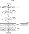
Fig. 15] Fig. 15 is a flowchart illustrating a method for controlling the input apparatus performed by the input apparatus illustrated inFig. 1 . - An input apparatus according to an embodiment of the present invention will be described hereinafter.
Fig. 1 is a schematic perspective view of aninput apparatus 100 according to the present embodiment. In an example, theinput apparatus 100 is located near a driver's seat of a vehicle, which is not illustrated. Theinput apparatus 100 is operated, for example, by a hand of an operator such as a driver. The operator holds anoperation member 110, which will be described later, by hand, moves theoperation member 110 on a two-dimensional plane, and requests a process by performing a determination operation, which will be described later. The process is, for example, selection of air conditioning inside the vehicle, a change to a set temperature of the air conditioning, or playback of music, but is not limited to these. - Herein x, y, and z directions perpendicular to one another are defined. The x direction generically indicates an x1 direction and an x2 direction, which are opposite each other. The y direction generically indicates a y1 direction and a y2 direction, which are opposite each other. The z direction generically indicates a z1 direction and a z2 direction, which are opposite each other. These directions are defined for the sake of convenience in order to explain relative positional relationships, and do not limit directions in actual use. Shapes of components are not limited to strict geometrical shapes based on expressions used regardless of whether a word "substantially" is used, insofar as a technical idea of the embodiment disclosed herein is achieved.
- As illustrated in
Fig. 1 , theinput apparatus 100 includes theoperation member 110 supported movably in accordance with a plurality of sections 190 (Fig. 5 ) set on the two-dimensional plane, a first driving device 111-1, a second driving device 111-2, a third driving device 111-3 (hereinafter might be generically referred to as "drivingdevices 111"), a first driving shaft 112-1, a second driving shaft 112-2, a third driving shaft 112-3 (hereinafter might be generically referred to as "drivingshafts 112"), a first gear 113-1, a second gear 113-2 (hereinafter might be generically referred to as "gears 113"), a first relay member 114-1, a second relay member 114-2 (hereinafter might be generically referred to as "relay members 114"), and acontrol device 115. - The
operation member 110 is a round column having a central axis extending in the z direction and is a flat disk extending on an x-y plane. Theoperation member 110 is not limited to the shape illustrated inFig. 1 but may be, for example, spherical. - The third driving shaft 112-3 is a substantially round columnar member extending in the z direction and rotates about a central axis extending in the z direction. An end of the third driving shaft 112-3 on a z2 side is fixed to a z1 side of the
operation member 110. Theoperation member 110 and the third driving shaft 112-3 are fixed to each other and move as one united body. The third driving device 111-3 rotates the third driving shaft 112-3 and detects the rotation of the third driving shaft 112-3. The third driving device 111-3 is supported by a chassis, which is not illustrated, in such a way as to be able to move in the x and y directions and not move in the z direction. Theoperation member 110, the third driving device 111-3, and the third driving shaft 112-3 move in the x and y directions as one united body. In another example, the third driving device 111-3 may be supported in such a way as to be move in the z direction, and theinput apparatus 100 may include a detection device that detects the movement of the third driving device 111-3 in the z direction. - The first relay member 114-1 is a substantially rectangular frame-like member that includes two straight line units extending in the x direction and two straight line units extending in the y direction and that extends on the x-y plane. The third driving device 111-3 is provided inside the first relay member 114-1. The first relay member 114-1 is supported by the chassis, which is not illustrated, in such a way as to be able to move in the x direction and not move in the z and y directions.
- The internal width of the first relay member 114-1 in the x direction is substantially the same as the width of the third driving device 111-3 in the x direction, and the third driving device 111-3 and the first relay member 114-1 move in the x direction as one united body. The internal width of the first relay member 114-1 in the y direction is greater than the width of the third driving device 111-3 in the y direction, and movement of the third driving device 111-3 in the y direction is not transmitted to the first relay member 114-1.
- The first driving shaft 112-1 is a substantially round columnar member extending in the y direction and rotates about a central axis extending in the y direction. The first driving device 111-1 rotates the first driving shaft 112-1 and detects the rotation of the first driving shaft 112-1. A y2 end of the first driving shaft 112-1 is fixed to a y1 end of the first gear 113-1. The first gear 113-1 and the first driving shaft 112-1 rotate about a central axis extending in the y direction as one united body. A gear groove formed in a part of the first relay member 114-1 on the z2 side engages with the first gear 113-1. When the first relay member 114-1 moves in the x direction, the first gear 113-1 rotates. When the first gear 113-1 rotates, the first relay member 114-1 moves in the x direction.
- The second relay member 114-2 is a substantially rectangular frame-like member that includes two straight line units extending in the x direction and two straight line units extending in the y direction and that extends on the x-y plane. The third driving device 111-3 is provided inside the second relay member 114-2. The second relay member 114-2 is supported by the chassis, which is not illustrated, in such a way as to be able to move in the y direction and not move in the z and x directions.
- The internal width of the second relay member 114-2 in the y direction is substantially the same as the width of the third driving device 111-3 in the y direction, and the third driving device 111-3 and the second relay member 114-2 move in the y direction as one united body. The internal width of the second relay member 114-2 in the x direction is greater than the width of the third driving device 111-3 in the x direction, and movement of the third driving device 111-3 in the x direction is not transmitted to the second relay member 114-2.
- The second driving shaft 112-2 is a substantially round columnar member extending in the x direction and rotates about a central axis extending in the x direction. The second driving device 111-2 rotates the second driving shaft 112-2 and detects the rotation of the second driving shaft 112-2. An x2 end of the second driving shaft 112-2 is fixed to an x1 end of the second gear 113-2. The second gear 113-2 and the second driving shaft 112-2 rotate about a central axis extending in the x direction as one united body. A gear groove formed in a part of the second relay member 114-2 on the z2 side engages with the second gear 113-2. When the second relay member 114-2 moves in the y direction, the second gear 113-2 rotates. When the second gear 113-2 rotates, the second relay member 114-2 moves in the y direction.
- That is, linear motion of the
operation member 110 in the x direction and rotational motion of the first driving shaft 112-1 are converted into each other. Linear motion of theoperation member 110 in the y direction and rotational motion of the second driving shaft 112-2 are converted into each other. Conversion of linear motion and rotational motion is not limited to the exemplary configuration described in the present embodiment. -
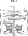
Fig. 2 is a diagram illustrating a schematic configuration of the drivingdevices 111 illustrated inFig. 1 . The threedriving devices 111 have the same configuration. The drivingdevices 111 each include arotation detection unit 121, atorque sensor 122, and aforce application unit 123. Therotation detection unit 121 is a rotary encoder, for example, and detects the rotational speed of the drivingshafts 112. Thetorque sensor 122 is of a magnetostrictive type, for example, and detects torque applied to the drivingshaft 112. Theforce application unit 123 includes a rotationalforce application section 124 and a resistingforce application section 125 and applies various types of force to the drivingshaft 112. - The rotational
force application section 124 is an electric motor. In an example, the rotationalforce application section 124 rotates the drivingshaft 112 on which a permanent magnet is mounted by varying current flowing into a coil in accordance with an instruction from the outside. - The resisting
force application section 125 includes atransmission member 131, acoil case 132, a magneticfield application portion 133, and amagnetorheological fluid 134. Thetransmission member 131 is a discal member extending around and from the drivingshaft 112. Thetransmission member 131 is fixed to the drivingshaft 112 and moves in accordance with movement of theoperation member 110. That is, the movement of thetransmission member 131 is transmitted to the operation member 110 (Fig. 1 ), and the movement of the operation member 110 (Fig. 1 ) is transmitted to thetransmission member 131. - The
coil case 132 is provided at a distance from the drivingshafts 112 in such a way as to surround the drivingshaft 112. The magneticfield application portion 133 is a coil inside thecoil case 132 that surrounds the drivingshaft 112 like a donut. Themagnetorheological fluid 134 is located between thecoil case 132 and thetransmission member 131 and in contact with both thecoil case 132 and thetransmission member 131. - As current supplied to the magnetic
field application portion 133 from the outside varies, a magnetic field applied to themagnetorheological fluid 134 varies. As the size of a magnetic field penetrating themagnetorheological fluid 134 varies in the direction in which the drivingshaft 112 extends, the cohesive strength of particles in themagnetorheological fluid 134 varies. As the cohesive strength varies, force (also called friction force) resisting relative movement between thetransmission member 131 and thecoil case 132 varies. - The operator feels the friction force caused in the resisting
force application section 125 as force resisting rotation. That is, the resistingforce application section 125 varies resisting force applied to the operation member 110 (Fig. 1 ) by varying resisting force between themagnetorheological fluid 134 and thetransmission member 131. -
Fig. 3 is a block diagram illustrating the configuration of the threedriving devices 111 and thecontrol device 115 illustrated inFig. 1 . Names of components of the first to third driving devices 111-1 to 111-3 are preceded by "first", "second", and "third" and followed by "-1", "-2", and "-3", respectively, for the purpose of distinction. Thecontrol device 115 includes astorage unit 150, anarithmetic processing unit 160, and adisplay unit 170. - The
storage unit 150 stores acontrol program 151, aconnection relationship 152, andnode information 153. Thecontrol program 151 is read by thearithmetic processing unit 160 and achieves a function of performing a part of a control method and other functions for thearithmetic processing unit 160. When thearithmetic processing unit 160 performs various functions, thestorage unit 150 is controlled by thearithmetic processing unit 160 and stores necessary information as necessary. Thestorage unit 150 is a physical non-transitory storage medium. Thestorage unit 150 includes a ROM (read-only memory) and a RAM (random-access memory). Thestorage unit 150 is a volatile or nonvolatile storage medium. Thestorage unit 150 may be removable or non-removable. -
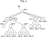
Fig. 4 is a diagram illustrating anexemplary connection relationship 152 between first to eighteenth nodes 180-1 to 180-18 (hereinafter might be generically referred to as nodes 180) stored in thestorage unit 150. The number of nodes 180 included in theconnection relationship 152 is not limited to 18. The relationship between the nodes 180 is not limited to that illustrated inFig. 4 . Representation of the connection is not limited to that illustrated inFig. 4 . - The nodes 180 include one or more nodes 180 connected to a higher node 180, one or more nodes 180 connected to one or more lower nodes, and one or more nodes 180 that are not connected to any of lower nodes 180.
- More specifically, the second to sixth nodes 180-2 to 180-6 are connected to the highest first node 180-1. The seventh to ninth nodes 180-7 to 180-9 are connected to the higher third node 180-3. The tenth to twelfth nodes 180-10 to 180-12 are connected to the higher fourth node 180-4. The thirteenth to fifteenth nodes 180-13 to 180-15 are connected to the higher eighth node 180-8. The sixteenth to eighteenth nodes 180-16 to 180-18 are connected to the higher ninth node 180-9.
- The
node information 153 illustrated inFig. 3 indicates information associated with the nodes 180 illustrated inFig. 4 . Information regarding the third node 180-3 illustrated inFig. 4 is "activation of an audio system". Information regarding the eighth node 180-8 is "activation of a television". Information regarding the ninth node 180-9 is "activation of a radio". Information regarding the tenth node 180-10 is "activation of a radio". Information regarding the seventeenth node 180-17 is "switching of frequency of a radio". - In
Fig. 4 , the third node 180-3 is illustrated as an example of a selectednode 181. The selectednode 181 is selected from the nodes 180 and switched in accordance with a position of the operation member 110 (Fig. 1 ) as described later. - The
arithmetic processing unit 160 illustrated inFig. 3 reads and executes thecontrol program 151 stored in thestorage unit 150 to function as aforce control section 161, asection detection section 162, anode selection section 163, adisplay control section 164, a determinationoperation detection section 165, and anexecution section 166. Thearithmetic processing unit 160 according to the present embodiment is a general-purpose computer but may be application-specific integrated circuit (ASIC) or another type of circuit into which the functions described in the present embodiment can be incorporated. - The
display unit 170 is a liquid crystal display, for example, and displays various images in accordance with instructions from thearithmetic processing unit 160. -
Fig. 5 is a diagram schematically illustrating a plurality ofsections 190 in an example. As illustrated inFig. 5 , thesections 190 are set as substantially square areas defined by two sides in an x direction and two sides in a y direction. All thesections 190 have the same shape. In another example, thesections 190 may have a different shape, instead. Sevensections 190 linearly arranged in the x direction form a row, and five rows are arranged in the y direction. In other words, fivesections 190 linearly arranged in the y direction form a column, and seven columns are arranged in the x direction. There are a total of 35sections 190. - Positions of the
sections 190 are expressed as (x, y) using an x coordinate of 0 to 6 and a y coordinate of 0 to 4. InFig. 5 , an exemplary position of theoperation member 110 at a certain time point is schematically indicated by a dot smaller than eachsection 190. The actual size of theoperation member 110 may be larger than eachsection 190.Sections 190 sharing the same y coordinate belong to the same layer.Sections 190 having a smaller y coordinate are regarded as being in a higher layer thansections 190 having a larger y coordinate.Sections 190 having a larger y coordinate are regarded as being in a lower layer thansections 190 having a smaller y coordinate. - The
operation member 110 is movably supported in the y1 direction (also referred to as a first forward direction), the y2 direction (also referred to as a first reverse direction), the x1 direction (also referred to as a second forward direction), and the x2 direction (also referred to as a second reverse direction). The first forward direction and the first reverse direction, which are opposite each other, are names for simply identifying directions. The second forward direction and the second reverse direction, which are opposite each other, are names for simply identifying directions. The first forward direction and the first reverse direction each intersect with both the second forward direction and the second reverse direction. -
Restricted sections 191 hatched inFig. 5 indicate a part of thesections 190 into which theoperation member 110 cannot move. Although a reference numeral is provided for only one restrictedsection 191 inFig. 5 , all the hatchedsections 190 will be referred to as restrictedsections 191. Permittedsections 192 that are not hatched indicate a part of thesections 190 within which theoperation member 110 can move. Although a reference numeral is provided for only one permittedsection 192 inFig. 5 , all thesections 190 that are not hatched will be referred to as permittedsections 192. The restrictedsections 191 and the permittedsections 192 are set in accordance with the position of theoperation member 110. Theoperation member 110 located at coordinates (3, 1) inFig. 5 , for example, can move between thesections 190 in the x1, x2, and y1 directions, but cannot move between the sections in the y2 direction. - A
determination target section 193 is assigned as, among the permittedsections 192, asection 190 in which a determination operation, which will be described later, is detected. Thedetermination target section 193 is assigned in accordance with the second node 180-2, the fifth to seventh nodes 180-5 to 180-7, and the tenth to eighteenth nodes 180-10 to 180-18, which do not have a lower node 180 inFig. 4 . - The
force control section 161 illustrated inFig. 3 controls force applied to the driving shafts 112 (Fig. 2 ) by the threeforce application unit 123 on the basis of outputs of the threerotation detection units 121 and the threetorque sensors 122. When one of the driving shafts 112 (Fig. 2 ) rotates in a rotation direction as a result of an operation performed by the operator, the rotationalforce application section 124 applies force to the driving shaft 112 (Fig. 2 ) in the rotation direction, and the operator feels acceleration. When the rotationalforce application section 124 applies force to the driving shaft 112 (Fig. 2 ) in a direction opposite the rotation direction, the operator feels resisting force. - The
force control section 161 adjusts resisting force applied to the driving shafts 112 (Fig. 2 ) by the resistingforce application section 125. The resistingforce application section 125, which employs themagnetorheological fluid 134, can apply a more distinct resisting force to the driving shafts 112 (Fig. 2 ) than the rotationalforce application section 124, which is an electric motor. Theforce control section 161 applies force to the driving shafts 112 (Fig. 2 ) while combining the rotationalforce application section 124 and the resistingforce application section 125 together. - The
force control section 161 applies force to the operation member 110 (Fig. 1 ) within each section 190 (Fig. 5 ) such that theoperation member 110 is pulled toward the center of the section 190 (Fig. 5 ). That is, when the operation member 110 (Fig. 1 ) is going out of one of the sections 190 (Fig. 5 ), theforce control section 161 applies resisting force in a direction opposite a moving direction of the operation member 110 (Fig. 1 ) using theforce application unit 123. As theoperation member 110 becomes farther from the center of the section 190 (Fig. 5 ) and closer to a boundary between thesection 190 and another section 190 (Fig. 5 ), the resisting force increases. Force necessary to move the operation member 110 (Fig. 1 ) from one section 190 (Fig. 5 ) to another is small enough for a person to produce by his/her hand. - Outputs of a first rotation detection unit 121-1, a second rotation detection unit 121-2, a first torque sensor 122-1, and a second torque sensor 122-2 that vary in accordance with the movement of the operation member 110 (
Fig. 1 ) on the x-y plane are mainly used to control force applied to the first driving shaft 112-1 (Fig. 1 ) and the second driving shaft 112-2 (Fig. 1 ). Outputs of a third rotation detection unit 121-3 and a third torque sensor 122-3 that vary in accordance with the rotation of the operation member 110 (Fig. 1 ) about a z axis are mainly used to control force applied to the third driving shaft 112-3 (Fig. 1 ). When the operator rotates the operation member 110 (Fig. 1 ), for example, resisting force is applied stepwise at a certain angle according to scale intervals of a dial. - The
section detection section 162 illustrated inFig. 3 detects a section 190 (Fig. 5 ) in which theoperation member 110 is located on the basis of the outputs of the first rotation detection unit 121-1, the first torque sensor 122-1, the second rotation detection unit 121-2, and the second torque sensor 122-2. - As illustrated in
Fig. 4 , thenode selection section 163 illustrated inFig. 3 selects one of the nodes 180 as a selectednode 181 in accordance with a detected section 190 (Fig. 5 ) in which theoperation member 110 is located. - Referring to
Fig. 4 , the node selection section 163 (Fig. 3 ) selects, as the operation member 110 (Fig. 5 ) moves in the y1 direction, a node 180 connected to a higher selectednode 181 before the movement as a selectednode 181. If the third node 180-3 is a selectednode 181 before movement, thenode selection section 163 selects the eighth node 180-8 as a selectednode 181 as the operation member 110 (Fig. 5 ) moves in the y1 direction. - The node selection section 163 (
Fig. 3 ) selects, as the operation member 110 (Fig. 5 ) moves in the y2 direction, a node 180 connected to a lower selectednode 181 before the movement as a selectednode 181. If the ninth node 180-9 is a selectednode 181 before movement, for example, thenode selection section 163 selects the third node 180-3 as a selectednode 181 as the operation member 110 (Fig. 5 ) moves in the y2 direction. - The node selection section 163 (
Fig. 3 ) switches, in accordance with movement of the operation member 110 (Fig. 5 ) in the x1 or x2 direction, the selectednode 181 between one or more nodes 180 connected to the same higher node 180. If the third node 180-3 is a selectednode 181 before movement, for example, the selectednode 181 is switched between the second to sixth nodes 180-2 to 180-6 in specified order in accordance with movement of theoperation member 110 in the x1 or x2 direction. - If a plurality of nodes 180 are connected to a higher node 180, the
operation member 110 can move to only one predetermined node 180 from the higher node 180 and to the higher node 180 from only the predetermined node 180. For example, theoperation member 110 can move to the eleventh node 180-11 from the fourth node 180-4 inFig. 4 , but cannot directly move to the tenth or twelfth node 180-10 or 180-12 from the fourth node 180-4. That is, the connection between the nodes 180 is a conceptual connection and does not necessarily indicate movability. - The
display control section 164 illustrated inFig. 3 generates an image to be displayed on thedisplay unit 170 to control visible display.Fig. 6 illustrates an example of an image displayed on thedisplay unit 170 when theoperation member 110 is located at the position illustrated inFig. 5 . - As illustrated in
Fig. 6 , the second to fifth nodes 180-2 to 180-5 are constantly displayed. An image indicating all lower nodes 180 (the second to sixth nodes 180-2 to 180-6 in the example illustrated inFig. 6 ) connected to a node 180 connected to a lower selectednode 181 and lower nodes 180 (the tenth to twelfth nodes 180-10 to 180-12) connected to the selectednode 181 is generated. - When a plurality of lower nodes 180 are connected to a higher node 180 in the
connection relationship 152 illustrated inFig. 4 , the higher node 180 is connected to one of the lower nodes 180 in the image illustrated inFig. 6 . The lower nodes 180 are horizontally arranged in a line, and adjacent lower nodes 180 are connected to each other by lines. In the image, the selectednode 181 is displayed differently from the other nodes 180. For example, the selectednode 181 is represented by a double circle. In another example, the selectednode 181 is highlighted by using a different color. - One of the
sections 190 illustrated inFig. 5 is assigned to each node 180 included in the image illustrated inFig. 6 . The assignment changes as theoperation member 110 moves. - The determination
operation detection section 165 illustrated inFig. 3 detects the determination operation performed by the operation member 110 (Fig. 1 ). Referring toFig. 5 , the determination operation is movement of theoperation member 110 in a determination direction, which is a direction parallel to the two-dimensional plane on which thesections 190 are arranged. The determination direction according to the present embodiment is the y1 direction. The determination direction is the same in alldetermination target sections 193, that is, the y1 direction. - The determination
operation detection section 165 detects movement of theoperation member 110, which is located in adetermination target section 193 among thesections 190, in the determination direction (y1 direction) as a determination operation. Movement of theoperation member 110 caused by pushing theoperation member 110 in the y1 direction at coordinates (4, 1), for example, is detected as a determination operation. The determination direction remains the same in anysection 190. A degree of pushing is set in advance. Theoperation member 110 need not go out of asection 190 or may move into anothersection 190. - Resisting force applied to the
operation member 110 when theoperation member 110 moves from adetermination target section 193 in the determination direction is different from resisting force applied to theoperation member 110 when theoperation member 110 moves betweensections 190 without a determination operation. Movement without a determination operation can be movement from asection 190 other than adetermination target section 193 to anothersection 190 or movement from adetermination target section 193 in a direction other than the determination direction. The resisting force applied to theoperation member 110 when theoperation member 110 moves from adetermination target section 193 in the determination direction is larger than the resisting force applied to theoperation member 110 when theoperation member 110 moves betweensections 190 without a determination operation. - When the
operation member 110 moves from asection 190 adjacent to a restrictedsection 191 to theadjacent section 191, the force control section 161 (Fig. 3 ) applies, to theoperation member 110, resisting force for preventing theoperation member 110 from going out of thesection 190 adjacent to the restrictedsection 191 using the force application unit 123 (Fig. 3 ). That is, when theoperation member 110 is pushed toward a hatchedrestricted section 191 from a non-hatched permittedsection 192, resisting force that is too large to be produced by a person's hand is applied to theoperation member 110. When theoperation member 110 is pushed toward a restrictedsection 191, distinct resisting force is generated using the resisting force application section 125 (Fig. 2 ), which employs the magnetorheological fluid 134 (Fig. 2 ), and applied to theoperation member 110 so that the operator can feel a boundary of asection 190. - The
execution section 166 illustrated inFig. 3 performs a process corresponding to asection 190 in which theoperation member 110 is located on the basis of thesection 190 detected by thesection detection section 162 and a determination operation detected by the determinationoperation detection section 165. Theexecution section 166 performs the process on the basis of information stored in thenode information 153 and associated with a selectednode 181. If a determination operation is performed at coordinates (5, 1) illustrated inFig. 5 , for example, theexecution section 166 performs the process on the basis of information regarding the sixth node 180-6 illustrated inFig. 6 , which corresponds to the coordinates (5, 1). The information associated with the sixth node 180-6 is, for example, "activation of an air conditioner". - The
execution section 166 illustrated inFig. 3 detects rotation of the operation member 110 (Fig. 1 ) on the basis of the outputs of the third rotation detection unit 121-3 and the third torque sensor 122-3, for example, and changes the temperature of an air conditioner in accordance with rotational speed. In order to prevent an erroneous operation, the operation member 110 (Fig. 1 ) may be firmly fixed while the operation member 110 (Fig. 1 ) is moving along the x-y plane. -
Fig. 5 is a diagram illustrating restricted sections 191 (hatched) and permitted sections 192 (not hatched) at a time when theoperation member 110 is located at the coordinates (3, 1). Adetermination target section 193 is at the coordinates (4, 1).Fig. 6 illustrates an image displayed on thedisplay unit 170 when a selectednode 181 is the fourth node 180-4. Lower nodes 180 connected to the fourth node 180-4, which is the selectednode 181, are displayed. - As illustrated in
Fig. 5 , fivesections 190 arranged in the x direction from coordinates (1, 1) to the coordinates (5, 1) correspond to the second to sixth nodes 180-2 to 180-6, respectively, illustrated inFig. 6 . As illustrated inFig. 5 , threesections 190 arranged in the x direction from coordinates (2, 2) to coordinates (4, 2) correspond to the tenth to twelfth nodes 180-10 to 180-12, respectively, illustrated inFig. 6 . -
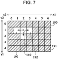
Fig. 7 is a diagram illustrating restricted sections 191 (hatched) and permitted sections 192 (not hatched) after theoperation member 110 illustrated inFig. 5 moves to coordinates (2, 1). Adetermination target section 193 is at the coordinates (1, 1).Fig. 8 illustrates an image displayed on thedisplay unit 170 when a selectednode 181 is the third node 180-3. In the image illustrated inFig. 8 , the lower nodes 180 connected to the fourth node 180-4 illustrated inFig. 6 are removed, and lower nodes 180 connected to the third node 180-3 are displayed. - Correspondences between sections 190 (
Fig. 7 ) in a layer (a y1 layer inFig. 7 ) to which the third node 180-3 belongs and the nodes 180 (Fig. 8 ) are the same as inFigs. 5 and6 . Correspondences in a layer immediately below the coordinates (2, 1) are changed. As illustrated inFig. 7 , threesections 190 arranged in the x direction from coordinates (1, 2) to coordinates (3, 2) correspond to the seventh to ninth nodes 180-7 to 180-9, respectively, illustrated inFig. 8 . -
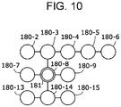
Fig. 9 is a diagram illustrating restricted sections 191 (hatched) and permitted sections 192 (not hatched) after theoperation member 110 illustrated inFig. 7 moves to the coordinates (2, 2). Adetermination target section 193 is at the coordinates (1, 2).Fig. 10 illustrates an image displayed on thedisplay unit 170 when a selectednode 181 is the eighth node 180-8. In the image illustrated inFig. 10 , lower nodes 180 connected to the eighth node 180-8 are displayed as well as the nodes 180 illustrated inFig. 8 . - Correspondences between sections 190 (
Fig. 9 ) in a layer (a y1 layer inFig. 9 ) to which the third node 180-3 belongs and a layer (a y2 layer inFig. 9 ) to which the eighth node 180-8 belongs and the nodes 180 (Fig. 10 ) are the same as inFigs. 7 and8 . Correspondences in a layer immediately below the coordinates (2, 2) are changed. As illustrated inFig. 9 , threesections 190 arranged in the x direction from coordinates (1, 3) to coordinates (3, 3) correspond to the thirteenth to fifteenth nodes 180-13 to 180-15, respectively, illustrated inFig. 10 . -
Fig. 11 is a diagram illustrating restricted sections 191 (hatched) and permitted sections 192 (not hatched) after theoperation member 110 illustrated inFig. 9 moves to the coordinates (3, 2). Adetermination target section 193 is at the coordinates (3, 3).Fig. 12 illustrates an image displayed on thedisplay unit 170 when a selectednode 181 is the ninth node 180-9. In the image illustrated inFig. 12 , the lower nodes 180 connected to the eighth node 180-8 illustrated inFig. 10 are removed, and lower nodes 180 connected to the ninth node 180-9 are displayed. - Correspondences between sections 190 (
Fig. 11 ) in a layer (a y1 layer inFig. 11 ) to which the third node 180-3 belongs and a layer (a y2 layer inFig. 11 ) to which the ninth node 180-9 belongs and the nodes 180 (Fig. 12 ) are the same as inFigs. 9 and10 . Correspondences in a layer immediately below the coordinates (3, 2) are changed. As illustrated inFig. 11 , threesections 190 arranged in the x direction from coordinates (2, 3) to coordinates (4, 3) correspond to the sixteenth to eighteenth nodes 180-16 to 180-18, respectively, illustrated inFig. 12 . -
Fig. 13 is a diagram illustrating restricted sections 191 (hatched) and permitted sections 192 (not hatched) after theoperation member 110 illustrated inFig. 11 moves to the coordinates (3, 3).Determination target sections 193 are at the coordinates (2, 3), (3, 3), and (4, 3).Fig. 14 illustrates an image displayed on thedisplay unit 170 when a selectednode 181 is the seventeenth node 180-17. Since no lower nodes 180 are connected to the seventeenth node 180-17, the nodes 180 illustrated inFig. 14 are the same as those illustrated inFig. 12 . Correspondences between the sections 190 (Fig. 13 ) in all layers and the nodes 180 (Fig. 14 ) are the same as inFigs. 11 and12 . - If a determination operation, that is, pushing of the
operation member 110 in the y1 direction (e.g., a predetermined movement such as a slight movement within asection 190 or a movement between sections 190), is performed when theoperation member 110 is located at the coordinates (3, 3) as illustrated inFig. 13 , the process is performed on the basis of information corresponding to the seventeenth node 180-17 illustrated inFig. 14 . Asection 190 at coordinates (3, 4) adjacent to asection 190 at the coordinates (3, 3) in the determination direction may be determined as arestricted section 191. -
Fig. 15 is a flowchart illustrating a method for controlling an input apparatus performed by the input apparatus 100 (Fig. 1 ) illustrated inFig. 1 . AlthoughFig. 13 is referred to as an example inFig. 15 , the position of theoperation member 110 may be different, instead. First, instep 201 illustrated inFig. 15 , the section detection section 162 (Fig. 3 ) detects a section 190 (Fig. 13 ) in which the operation member 110 (Fig. 13 ) is located. In the example illustrated inFig. 13 , theoperation member 110 is located in thesection 190 at the coordinates (3, 3). - Next, in
step 202 illustrated inFig. 15 , the determination operation detection section 165 (Fig. 3 ) determines whether the operation member 110 (Fig. 13 ) is located in a determination target section 193 (Fig. 13 ). In the example illustrated inFig. 13 , theoperation member 110 is located in adetermination target section 193. If it is determined instep 202 illustrated inFig. 15 that theoperation member 110 is located in a determination target section 193 (Fig. 13 ), the determination operation detection section 165 (Fig. 3 ) determines instep 203 whether the operation member 110 (Fig. 13 ) has moved from the determination target section 193 (Fig. 13 ) in the determination direction (i.e., the y1 direction). - If it is determined in
step 202 that the operation member 110 (Fig. 13 ) is not located in a determination target section 193 (Fig. 13 ), or if it is determined instep 203 that the operation member 110 (Fig. 13 ) has not moved from the determination target section 193 (Fig. 13 ) in the determination direction, the node selection section 163 (Fig. 3 ) changes, instep 204, a selected node 181 (Fig. 13 ) in accordance with movement between sections 190 (Fig. 13 ). A method for changing the selectednode 181 is as described with reference toFigs. 5 to 14 . Afterstep 204, the method ends. - If it is determined in
step 203 that the operation member 110 (Fig. 13 ) has moved from the determination target section 193 (Fig. 13 ) in the determination direction, the determination operation detection section 165 (Fig. 3 ) determines instep 205 that the determination operation has been performed. Afterstep 205, the execution section 166 (Fig. 3 ) performs, instep 206, various processes on the basis of information stored in the node information 153 (Fig. 3 ) and associated with the selected node 181 (Fig. 14 ). - If the determination operation is performed at the coordinates (3, 3) illustrated in
Fig. 13 , for example, a process is performed on the basis of information associated with the seventeenth node 180-17 illustrated inFig. 14 . For example, "switching of frequency of a radio", which is associated with the seventeenth node 180-17, is performed. Afterstep 206, the method ends. The method for controlling an input apparatus is repeatedly performed. - The present embodiment is the
input apparatus 100 including theoperation member 110 supported movably in accordance with the plurality ofsections 190 set on the two-dimensional plane, thesection detection section 162 that detects asection 190 in which theoperation member 110 is located, the determinationoperation detection section 165 that detects the determination operation performed using theoperation member 110, and theexecution section 166 that performs a process corresponding to thesection 190 in which theoperation member 110 is located on the basis of thesection 190 detected by thesection detection section 162 and the determination operation detected by the determinationoperation detection section 165. The determination operation is movement of theoperation member 110 in the determination direction (y1 direction), which is a direction parallel to the two-dimensional plane. - With this configuration, if a determination operation is performed separately from movement of the
operation member 110 to asection 190, a process corresponding to thesection 190 in which theoperation member 110 is located is performed. Compared to when the determination operation is not necessary, therefore, an unintended process tends to be prevented. Since the determination operation is performed through an operation along the two-dimensional plane, structure and operation are simpler than when a switch is separately provided for the determination operation. In addition, structure and operation are simpler than when an operation other than movement along the two-dimensional plane is necessary. - More preferably, in the
input apparatus 100 in the present disclosure, the plurality ofsections 190 include a plurality ofdetermination target sections 193 assigned as sections for the determination operation. The determination direction is the same in all thedetermination target sections 193. - With this configuration, since the determination direction is the same in all the
determination target sections 193, operation is simpler than when the determination direction is different between thedetermination target sections 193, and an unintended operation can be easily prevented. - More preferably, the
input apparatus 100 in the present disclosure further includes aforce application unit 123 that applies force to the operation member. If theoperation member 110 is going out of thesection 190, the force application unit applies, to theoperation member 110, resisting force whose direction is opposite a direction in which the operation member is moving. - With this configuration, the
operation member 110 can be distinctly moved to eachsection 190 compared to when resisting force is not applied, and an unintended operation can be easily prevented. - More preferably, in the
input apparatus 100 in the present disclosure, magnitude of the resisting force applied to theoperation member 110 when theoperation member 110 moves in the determination direction is different from magnitude of the resisting force applied to theoperation member 110 when theoperation member 110 moves between the plurality ofsections 190. - With this configuration, since the magnitude of resisting force felt by the operator is different between the determination operation and the movement between the
sections 190, an unintended operation tends to be prevented. - More preferably, in the
input apparatus 100 in the present disclosure, the resisting force applied to theoperation member 110 when theoperation member 110 moves from one of thedetermination target sections 193 in the determination direction is larger than the resisting force applied to theoperation member 110 when theoperation member 110 moves between the plurality ofsections 190. - With this configuration, since force felt by the operator when the operator performs the determination operation is larger than force felt by the operator when the operator moves the operation member between the
sections 190, the operator can be prevented from unintendedly performing the determination operation when he/she actually intends to move the operation member between thesections 190. - More preferably, in the
input apparatus 100 in the present disclosure, the plurality ofsections 190 include a restrictedsection 191. When the operation member moves from thesection 190 adjacent to the restrictedsection 191 to the restrictedsection 191, theforce application unit 123 applies, to theoperation member 110, the resisting force for preventing theoperation member 110 from going out of thesection 190 adjacent to the restrictedsection 191. - With this configuration, since the resisting force prevents the
operation member 110 from going out of asection 190 in a restricted direction, the operator can accurately move theoperation member 110 alongsections 190. - More preferably, the
input apparatus 100 in the present disclosure further includes atransmission member 131 that moves in accordance with the movement of theoperation member 110. Theforce application unit 123 includes a resistingforce application section 125. The resistingforce application section 125 includes amagnetorheological fluid 134 in contact with thetransmission member 131 and a magneticfield application portion 133 that applies a magnetic field to themagnetorheological fluid 134. The resistingforce application section 125 changes the resisting force applied to theoperation member 110 by changing the resisting force between themagnetorheological fluid 134 and thetransmission member 131. - With this configuration, since the resisting force can be precisely changed electrically, the resisting force for preventing an unintended operation can be applied more accurately. Distinct resisting force can be applied compared to especially when resisting force is applied only through rotation of an electric motor. The operator can therefore distinctly feel borders between the
sections 190. - More preferably, the
input apparatus 100 in the present disclosure further includes astorage unit 150 storing aconnection relationship 152 between a plurality of nodes 180 and information associated with each of the plurality of nodes 180 and anode selection section 163 that selects one of the plurality of nodes 180 as a selectednode 181 in accordance with a detected position of theoperation member 110. Theoperation member 110 is supported movably in a first forward direction (y1 direction), a first reverse direction (y2 direction), a second forward direction (x1 direction), and a second reverse direction (x2 direction). The first forward direction and the first reverse direction are opposite each other. The second forward direction and the second reverse direction are opposite each other. The first forward direction and the first reverse direction each intersect with both the second forward direction and the second reverse direction. The plurality of nodes 180 include the one or more nodes 180 connected to the higher node 180. The plurality of nodes 180 include the one or more nodes 180 connected to the lower node 180 and the one or more nodes 180 not connected to any lower node 180. Thenode selection section 163 selects, in accordance with movement of theoperation member 110 in the first forward direction, the lower node 180 connected to the selected node before the movement as the selectednode 181. Thenode selection section 163 selects, in accordance with movement of theoperation member 110 in the first reverse direction, the higher node 180 connected to the selectednode 181 before the movement as the selectednode 181. Thenode selection section 163 switches, in accordance with movement of theoperation member 110 in the second forward direction or the second reverse direction, the selectednode 181 between the one or more nodes 180 connected to the same higher node 180. The first forward direction is the determination direction. Theexecution section 166 performs the process on a basis of the information associated with the selectednode 181. - With this configuration, since a movement direction from a higher node 180 to a lower node 180 is the same as the determination direction, the operator can intuitively perform operations. As a result, an unintended operation can be easily prevented.
- More preferably, the
input apparatus 100 in the present disclosure further includes adisplay control section 164 that controls visible display. Thedisplay control section 164 generates an image indicating all the lower nodes 180 connected to the higher node 180 connected to the selectednode 181 and the lower node 180 connected to the selectednode 181. Thedisplay control section 164 displays the selectednode 181 in the image differently from the other nodes 180. - With this configuration, since the operator can select a selected
node 181 while checking an image indicating nodes 180 close to the selectednode 181, an operation that is not intended by the operator can be easily prevented. - More preferably, the
input apparatus 100 in the present disclosure further includes a drivingshaft 112 that rotatably supports theoperation member 110 and arotation detection unit 121 that detects a rotation state of the drivingshaft 112. - With this configuration, since an input can be made through not only movement of the
operation member 110 along the two-dimensional plane but also rotation of theoperation member 110, various inputs can be made promptly. - The present invention is not limited to the above-described embodiment. That is, those skilled in the art may carry out modification, combination, sub-combination, and substitution in various ways for the components according to the above-described embodiment within the technical scope of the present invention or a scope equivalent thereto.
- The present invention can be applied to an input apparatus that involves movement of an operation member and a determination operation.
-
- 100 input apparatus, 110 operation member, 111 driving device, 112 driving shaft,
- 115 control device, 121 rotation detection unit, 122 torque sensor, 123 force application unit,
- 124 rotational force application section, 125 resisting force application section, 131 transmission member,
- 133 magnetic field application section, 134 magnetorheological fluid, 150 storage unit,
- 151 control program, 152 connection relationship, 153 node information,
- 160 arithmetic processing unit, 161 force control section,
- 162 section detection section,
- 163 node selection section, 164 display control section,
- 165 determination operation detection section,
- 166 execution section, 180 node, 181 selected node, 190 section,
- 191 restricted section, 192 permitted section, 193 determination target section
Claims (12)
- An input apparatus comprising:an operation member supported movably in accordance with a plurality of sections set on a two-dimensional plane;a section detection section that detects a section in which the operation member is located;a determination operation detection section that detects a determination operation performed using the operation member; andan execution section that performs a process corresponding to the section in which the operation member is located on a basis of the section detected by the section detection section and the determination operation detected by the determination operation detection section,wherein the determination operation is movement of the operation member in a determination direction, which is a direction parallel to the two-dimensional plane.
- The input apparatus according to Claim 1,
wherein the plurality of sections include a plurality of determination target sections assigned as sections for the determination operation, and
wherein the determination direction is the same in all the determination target sections. - The input apparatus according to Claim 1 or 2, further comprising:a force application unit that applies force to the operation member,wherein, if the operation member is going out of the section, the force application unit applies, to the operation member, resisting force whose direction is opposite a direction in which the operation member is moving.
- The input apparatus according to Claim 3,
wherein magnitude of the resisting force applied to the operation member when the operation member moves in the determination direction is different from magnitude of the resisting force applied to the operation member when the operation member moves between the plurality of sections. - The input apparatus according to Claim 3 or 4,
wherein the plurality of sections include a plurality of determination target sections assigned as sections for the determination operation, and
wherein the resisting force applied to the operation member when the operation member moves from one of the determination target sections in the determination direction is larger than the resisting force applied to the operation member when the operation member moves between the plurality of sections. - The input apparatus according to any of Claims 3 to 5,
wherein the plurality of sections include a restricted section, and
wherein, when the operation member moves from a section adjacent to the restricted section to the restricted section, the force application unit applies, to the operation member, the resisting force for preventing the operation member from going out of the section adjacent to the restricted section. - The input apparatus according to any of Claims 3 to 6, further comprising:a transmission member that moves in accordance with the movement of the operation member,wherein the force application unit includes a resisting force application section,wherein the resisting force application section includesa magnetorheological fluid in contact with the transmission member, anda magnetic field application portion that applies a magnetic field to the magnetorheological fluid, and wherein the resisting force application section changes the resisting force applied to the operation member by changing the resisting force between the magnetorheological fluid and the transmission member.
- The input apparatus according to any of Claims 1 to 7, further comprising:a storage unit storing a connection relationship between a plurality of nodes and information associated with each of the plurality of nodes; anda node selection section that selects one of the plurality of nodes as a selected node in accordance with a detected position of the operation member,wherein the operation member is supported movably in a first forward direction, a first reverse direction, a second forward direction, and a second reverse direction,wherein the first forward direction and the first reverse direction are opposite each other,wherein the second forward direction and the second reverse direction are opposite each other,wherein the first forward direction and the first reverse direction each intersect with both the second forward direction and the second reverse direction,wherein the plurality of nodes include the one or more nodes connected to the higher node,wherein the plurality of nodes include the one or more nodes connected to the lower node and the one or more nodes not connected to any of the lower nodes,wherein the node selection section selects, in accordance with movement of the operation member in the first forward direction, the lower node connected to the selected node before the movement as the selected node,wherein the node selection section selects, in accordance with movement of the operation member in the first reverse direction, the higher node connected to the selected node before the movement as the selected node,wherein the node selection section switches, in accordance with movement of the operation member in the second forward direction or the second reverse direction, the selected node between the one or more nodes connected to the same higher node,wherein the first forward direction is the determination direction, andwherein the execution section performs the process on a basis of the information associated with the selected node.
- The input apparatus according to Claim 8, further comprising:a display control section that controls visible display,wherein the display control section generates an image indicating all the lower nodes connected to the node connected to the lower selected node and the lower node connected to the selected node, andwherein the display control section displays the selected node in the image differently from the other nodes.
- The input apparatus according to any of Claims 1 to 9, further comprising:a driving shaft that rotatably supports the operation member; anda rotation detection unit that detects a rotation state of the driving shaft.
- A method for controlling an input apparatus performed by the input apparatus, which includes an operation member supported movably in accordance with a plurality of sections set on a two-dimensional plane, the method comprising:detecting a section in which the operation member is located;detecting a determination operation performed using the operation member; andperforming a process corresponding to the section in which the operation member is located on a basis of the detected section and the detected determination operation,wherein the determination operation is movement of the operation member in a determination direction, which is a direction parallel to the two-dimensional plane.
- A control program causing a computer to perform the method for controlling an input apparatus according to Claim 11.
Applications Claiming Priority (2)
| Application Number | Priority Date | Filing Date | Title |
|---|---|---|---|
| JP2017141688 | 2017-07-21 | ||
| PCT/JP2018/026585 WO2019017306A1 (en) | 2017-07-21 | 2018-07-13 | Input device, input device control method, and control program |
Publications (2)
| Publication Number | Publication Date |
|---|---|
| EP3657304A1 true EP3657304A1 (en) | 2020-05-27 |
| EP3657304A4 EP3657304A4 (en) | 2021-04-14 |
Family
ID=65015217
Family Applications (1)
| Application Number | Title | Priority Date | Filing Date |
|---|---|---|---|
| EP18835396.5A Withdrawn EP3657304A4 (en) | 2017-07-21 | 2018-07-13 | Input device, input device control method, and control program |
Country Status (5)
| Country | Link |
|---|---|
| US (1) | US11086350B2 (en) |
| EP (1) | EP3657304A4 (en) |
| JP (1) | JP6817444B2 (en) |
| CN (1) | CN110945462B (en) |
| WO (1) | WO2019017306A1 (en) |
Families Citing this family (9)
| Publication number | Priority date | Publication date | Assignee | Title |
|---|---|---|---|---|
| DE102016015155A1 (en) * | 2016-05-13 | 2017-11-16 | Liebherr-Werk Bischofshofen Gmbh | Arrangement for controlling a work machine |
| US20210340724A1 (en) | 2020-05-01 | 2021-11-04 | Deere & Company | Work vehicle magnetorheological fluid joystick systems providing machine state feedback |
| US11681320B2 (en) | 2020-05-01 | 2023-06-20 | Deere & Company | Work vehicle magnetorheological fluid joystick systems operable in modified centering modes |
| US11634885B2 (en) | 2020-05-01 | 2023-04-25 | Deere & Company | Work vehicle magnetorheological fluid joystick systems reducing unintended joystick motions |
| US11499292B2 (en) | 2020-05-01 | 2022-11-15 | Deere & Company | Magnetorheological fluid joystick systems reducing work vehicle mispositioning |
| WO2022107258A1 (en) * | 2020-11-18 | 2022-05-27 | 任天堂株式会社 | Information processing system, controller, information processing method, and information processing program |
| WO2022123737A1 (en) * | 2020-12-10 | 2022-06-16 | 任天堂株式会社 | Information processing system, controller, information processing method, and information processing program |
| US11599136B1 (en) * | 2022-01-11 | 2023-03-07 | Dell Products L.P. | Magnetorheological fluid (MRF) rotary damper for adaptive user input device |
| JP2024075941A (en) * | 2022-11-24 | 2024-06-05 | ヤンマーホールディングス株式会社 | CONTROL METHOD FOR CONTROLLING A WORK MACHINE, CONTROL PROGRAM FOR CONTROLLING A WORK MACHINE, AND CONTROL SYSTEM FOR CONTROLLING A WORK MACHINE |
Family Cites Families (13)
| Publication number | Priority date | Publication date | Assignee | Title |
|---|---|---|---|---|
| JP3850619B2 (en) * | 1999-07-14 | 2006-11-29 | アルプス電気株式会社 | In-vehicle input device |
| JP2003031074A (en) * | 2001-07-11 | 2003-01-31 | Alps Electric Co Ltd | Input device |
| JP3868856B2 (en) * | 2002-06-19 | 2007-01-17 | アルプス電気株式会社 | Multi-directional input device |
| JP2005063228A (en) * | 2003-08-15 | 2005-03-10 | Alps Electric Co Ltd | Input device |
| US20050159850A1 (en) * | 2004-01-16 | 2005-07-21 | Emanuel Melman | Shift knob computer operating device |
| JP4802160B2 (en) | 2007-08-24 | 2011-10-26 | 株式会社デンソー | In-vehicle input device |
| CN102037429A (en) * | 2008-03-20 | 2011-04-27 | 英诺晶片科技股份有限公司 | Electronic device and a pointer motion control method thereof |
| US8436814B2 (en) * | 2008-09-25 | 2013-05-07 | Denso Corporation | In-vehicle manipulation apparatus and in-vehicle input apparatus |
| JP5234524B2 (en) * | 2010-04-27 | 2013-07-10 | 株式会社デンソー | Vehicle operation input device |
| US9201559B2 (en) * | 2011-11-14 | 2015-12-01 | Logitech Europe S.A. | Method of operating a multi-zone input device |
| JP6004427B2 (en) * | 2012-06-21 | 2016-10-05 | 株式会社ワコム | Indicator operation detection device |
| JP5754483B2 (en) * | 2012-12-24 | 2015-07-29 | 株式会社デンソー | Operation device |
| JP6176702B2 (en) * | 2013-03-08 | 2017-08-09 | 株式会社栗本鐵工所 | Joystick device |
-
2018
- 2018-07-13 CN CN201880048389.3A patent/CN110945462B/en active Active
- 2018-07-13 JP JP2019531017A patent/JP6817444B2/en active Active
- 2018-07-13 WO PCT/JP2018/026585 patent/WO2019017306A1/en not_active Ceased
- 2018-07-13 EP EP18835396.5A patent/EP3657304A4/en not_active Withdrawn
-
2019
- 2019-12-18 US US16/719,526 patent/US11086350B2/en active Active
Also Published As
| Publication number | Publication date |
|---|---|
| WO2019017306A1 (en) | 2019-01-24 |
| JP6817444B2 (en) | 2021-01-20 |
| JPWO2019017306A1 (en) | 2020-07-30 |
| US20200125132A1 (en) | 2020-04-23 |
| US11086350B2 (en) | 2021-08-10 |
| CN110945462B (en) | 2023-06-09 |
| EP3657304A4 (en) | 2021-04-14 |
| CN110945462A (en) | 2020-03-31 |
Similar Documents
| Publication | Publication Date | Title |
|---|---|---|
| US11086350B2 (en) | Input apparatus, method for controlling input apparatus, and control program | |
| TWI702408B (en) | Control method of touch display apparatus | |
| JP5005413B2 (en) | In-vehicle device controller | |
| CN104071097B (en) | Input apparatus, input method, and input program | |
| JP5641001B2 (en) | Display control apparatus and display system | |
| US20090082960A1 (en) | Navigation system with enhanced display functions | |
| KR101803222B1 (en) | User interface and method for signalling a 3d position of input means during gesture detection | |
| JP4836050B2 (en) | Input system for in-vehicle electronic devices | |
| KR20130036253A (en) | Method and device for providing a user interface | |
| CA2847421C (en) | Selection of objects in a three-dimensional virtual scenario | |
| KR101664038B1 (en) | Concentration manipulation system for vehicle | |
| KR20130067110A (en) | Menu operation device and method in vehicles | |
| EP2666660A1 (en) | Vehicle information display | |
| JP2002108564A (en) | Touch panel inputting device | |
| JP5790578B2 (en) | Display system, display device, and operation device | |
| WO2015083267A1 (en) | Display control device, and display control method | |
| JP5725368B2 (en) | Tactile display, operation input device, and operation input system | |
| JP5234524B2 (en) | Vehicle operation input device | |
| JP4751844B2 (en) | Operation input device | |
| US20040012361A1 (en) | Operating unit | |
| WO2014188254A1 (en) | Map display controller and map display control system | |
| KR20210085915A (en) | Shift range switching appratus for selecting and displaying shifting range on steering wheel and a method for controlling the same | |
| KR102416642B1 (en) | Trackball apparatus and screen control system for vehicle display device using the same | |
| JP2013060115A (en) | Vehicle-mounted display device | |
| JP2019032886A (en) | Display control device, display control method, and display control device program |
Legal Events
| Date | Code | Title | Description |
|---|---|---|---|
| STAA | Information on the status of an ep patent application or granted ep patent |
Free format text: STATUS: THE INTERNATIONAL PUBLICATION HAS BEEN MADE |
|
| PUAI | Public reference made under article 153(3) epc to a published international application that has entered the european phase |
Free format text: ORIGINAL CODE: 0009012 |
|
| STAA | Information on the status of an ep patent application or granted ep patent |
Free format text: STATUS: REQUEST FOR EXAMINATION WAS MADE |
|
| 17P | Request for examination filed |
Effective date: 20191111 |
|
| AK | Designated contracting states |
Kind code of ref document: A1 Designated state(s): AL AT BE BG CH CY CZ DE DK EE ES FI FR GB GR HR HU IE IS IT LI LT LU LV MC MK MT NL NO PL PT RO RS SE SI SK SM TR |
|
| AX | Request for extension of the european patent |
Extension state: BA ME |
|
| DAV | Request for validation of the european patent (deleted) | ||
| DAX | Request for extension of the european patent (deleted) | ||
| A4 | Supplementary search report drawn up and despatched |
Effective date: 20210315 |
|
| RIC1 | Information provided on ipc code assigned before grant |
Ipc: G06F 3/0338 20130101AFI20210309BHEP Ipc: G05G 1/02 20060101ALI20210309BHEP Ipc: G05G 1/08 20060101ALI20210309BHEP Ipc: G05G 5/03 20080401ALI20210309BHEP Ipc: G06F 3/0354 20130101ALI20210309BHEP |
|
| STAA | Information on the status of an ep patent application or granted ep patent |
Free format text: STATUS: THE APPLICATION HAS BEEN WITHDRAWN |
|
| 18W | Application withdrawn |
Effective date: 20210519 |