EP3657278A1 - Method and apparatus for proxy execution and computation with an industrial controller - Google Patents
Method and apparatus for proxy execution and computation with an industrial controller Download PDFInfo
- Publication number
- EP3657278A1 EP3657278A1 EP19208521.5A EP19208521A EP3657278A1 EP 3657278 A1 EP3657278 A1 EP 3657278A1 EP 19208521 A EP19208521 A EP 19208521A EP 3657278 A1 EP3657278 A1 EP 3657278A1
- Authority
- EP
- European Patent Office
- Prior art keywords
- external processing
- processing device
- processor
- industrial controller
- data
- Prior art date
- Legal status (The legal status is an assumption and is not a legal conclusion. Google has not performed a legal analysis and makes no representation as to the accuracy of the status listed.)
- Granted
Links
Images


Classifications
-
- G—PHYSICS
- G05—CONTROLLING; REGULATING
- G05B—CONTROL OR REGULATING SYSTEMS IN GENERAL; FUNCTIONAL ELEMENTS OF SUCH SYSTEMS; MONITORING OR TESTING ARRANGEMENTS FOR SUCH SYSTEMS OR ELEMENTS
- G05B19/00—Program-control systems
- G05B19/02—Program-control systems electric
- G05B19/04—Program control other than numerical control, i.e. in sequence controllers or logic controllers
- G05B19/05—Programmable logic controllers, e.g. simulating logic interconnections of signals according to ladder diagrams or function charts
- G05B19/056—Programming the PLC
-
- G—PHYSICS
- G05—CONTROLLING; REGULATING
- G05B—CONTROL OR REGULATING SYSTEMS IN GENERAL; FUNCTIONAL ELEMENTS OF SUCH SYSTEMS; MONITORING OR TESTING ARRANGEMENTS FOR SUCH SYSTEMS OR ELEMENTS
- G05B19/00—Program-control systems
- G05B19/02—Program-control systems electric
- G05B19/04—Program control other than numerical control, i.e. in sequence controllers or logic controllers
- G05B19/05—Programmable logic controllers, e.g. simulating logic interconnections of signals according to ladder diagrams or function charts
- G05B19/052—Linking several PLC's
-
- G—PHYSICS
- G05—CONTROLLING; REGULATING
- G05B—CONTROL OR REGULATING SYSTEMS IN GENERAL; FUNCTIONAL ELEMENTS OF SUCH SYSTEMS; MONITORING OR TESTING ARRANGEMENTS FOR SUCH SYSTEMS OR ELEMENTS
- G05B19/00—Program-control systems
- G05B19/02—Program-control systems electric
- G05B19/418—Total factory control, i.e. centrally controlling a plurality of machines, e.g. direct or distributed numerical control [DNC], flexible manufacturing systems [FMS], integrated manufacturing systems [IMS] or computer integrated manufacturing [CIM]
- G05B19/4183—Total factory control, i.e. centrally controlling a plurality of machines, e.g. direct or distributed numerical control [DNC], flexible manufacturing systems [FMS], integrated manufacturing systems [IMS] or computer integrated manufacturing [CIM] characterised by data acquisition, e.g. workpiece identification
-
- G—PHYSICS
- G05—CONTROLLING; REGULATING
- G05B—CONTROL OR REGULATING SYSTEMS IN GENERAL; FUNCTIONAL ELEMENTS OF SUCH SYSTEMS; MONITORING OR TESTING ARRANGEMENTS FOR SUCH SYSTEMS OR ELEMENTS
- G05B19/00—Program-control systems
- G05B19/02—Program-control systems electric
- G05B19/04—Program control other than numerical control, i.e. in sequence controllers or logic controllers
- G05B19/045—Program control other than numerical control, i.e. in sequence controllers or logic controllers using logic state machines, consisting only of a memory or a programmable logic device containing the logic for the controlled machine and in which the state of its outputs is dependent on the state of its inputs or part of its own output states, e.g. binary decision controllers, finite state controllers
-
- G—PHYSICS
- G05—CONTROLLING; REGULATING
- G05B—CONTROL OR REGULATING SYSTEMS IN GENERAL; FUNCTIONAL ELEMENTS OF SUCH SYSTEMS; MONITORING OR TESTING ARRANGEMENTS FOR SUCH SYSTEMS OR ELEMENTS
- G05B19/00—Program-control systems
- G05B19/02—Program-control systems electric
- G05B19/04—Program control other than numerical control, i.e. in sequence controllers or logic controllers
- G05B19/05—Programmable logic controllers, e.g. simulating logic interconnections of signals according to ladder diagrams or function charts
- G05B19/054—Input/output
-
- G—PHYSICS
- G05—CONTROLLING; REGULATING
- G05B—CONTROL OR REGULATING SYSTEMS IN GENERAL; FUNCTIONAL ELEMENTS OF SUCH SYSTEMS; MONITORING OR TESTING ARRANGEMENTS FOR SUCH SYSTEMS OR ELEMENTS
- G05B19/00—Program-control systems
- G05B19/02—Program-control systems electric
- G05B19/04—Program control other than numerical control, i.e. in sequence controllers or logic controllers
- G05B19/05—Programmable logic controllers, e.g. simulating logic interconnections of signals according to ladder diagrams or function charts
- G05B19/058—Safety, monitoring
-
- G—PHYSICS
- G06—COMPUTING OR CALCULATING; COUNTING
- G06F—ELECTRIC DIGITAL DATA PROCESSING
- G06F1/00—Details not covered by groups G06F3/00 - G06F13/00 and G06F21/00
- G06F1/02—Digital function generators
- G06F1/03—Digital function generators working, at least partly, by table look-up
-
- G—PHYSICS
- G05—CONTROLLING; REGULATING
- G05B—CONTROL OR REGULATING SYSTEMS IN GENERAL; FUNCTIONAL ELEMENTS OF SUCH SYSTEMS; MONITORING OR TESTING ARRANGEMENTS FOR SUCH SYSTEMS OR ELEMENTS
- G05B2219/00—Program-control systems
- G05B2219/10—Plc systems
- G05B2219/12—Plc mp multi processor system
- G05B2219/1203—Expand logical expression over multiple controllers
-
- G—PHYSICS
- G05—CONTROLLING; REGULATING
- G05B—CONTROL OR REGULATING SYSTEMS IN GENERAL; FUNCTIONAL ELEMENTS OF SUCH SYSTEMS; MONITORING OR TESTING ARRANGEMENTS FOR SUCH SYSTEMS OR ELEMENTS
- G05B2219/00—Program-control systems
- G05B2219/10—Plc systems
- G05B2219/12—Plc mp multi processor system
- G05B2219/1204—Multiprocessing, several plc's, distributed logic control
-
- G—PHYSICS
- G05—CONTROLLING; REGULATING
- G05B—CONTROL OR REGULATING SYSTEMS IN GENERAL; FUNCTIONAL ELEMENTS OF SUCH SYSTEMS; MONITORING OR TESTING ARRANGEMENTS FOR SUCH SYSTEMS OR ELEMENTS
- G05B2219/00—Program-control systems
- G05B2219/10—Plc systems
- G05B2219/13—Plc programming
- G05B2219/13009—State machine instructions
-
- G—PHYSICS
- G05—CONTROLLING; REGULATING
- G05B—CONTROL OR REGULATING SYSTEMS IN GENERAL; FUNCTIONAL ELEMENTS OF SUCH SYSTEMS; MONITORING OR TESTING ARRANGEMENTS FOR SUCH SYSTEMS OR ELEMENTS
- G05B2219/00—Program-control systems
- G05B2219/10—Plc systems
- G05B2219/13—Plc programming
- G05B2219/13058—One instruction of plc generates a whole independent sequence, relay
-
- G—PHYSICS
- G05—CONTROLLING; REGULATING
- G05B—CONTROL OR REGULATING SYSTEMS IN GENERAL; FUNCTIONAL ELEMENTS OF SUCH SYSTEMS; MONITORING OR TESTING ARRANGEMENTS FOR SUCH SYSTEMS OR ELEMENTS
- G05B2219/00—Program-control systems
- G05B2219/10—Plc systems
- G05B2219/13—Plc programming
- G05B2219/13073—Several interacting programs, each for a separate machine, exchange of start, stop
-
- G—PHYSICS
- G05—CONTROLLING; REGULATING
- G05B—CONTROL OR REGULATING SYSTEMS IN GENERAL; FUNCTIONAL ELEMENTS OF SUCH SYSTEMS; MONITORING OR TESTING ARRANGEMENTS FOR SUCH SYSTEMS OR ELEMENTS
- G05B2219/00—Program-control systems
- G05B2219/10—Plc systems
- G05B2219/13—Plc programming
- G05B2219/13164—Remote and local programming unit, control panel
-
- G—PHYSICS
- G05—CONTROLLING; REGULATING
- G05B—CONTROL OR REGULATING SYSTEMS IN GENERAL; FUNCTIONAL ELEMENTS OF SUCH SYSTEMS; MONITORING OR TESTING ARRANGEMENTS FOR SUCH SYSTEMS OR ELEMENTS
- G05B2219/00—Program-control systems
- G05B2219/30—Nc systems
- G05B2219/31—From computer integrated manufacturing till monitoring
- G05B2219/31334—Database with devices, configuration, of plant
Definitions
- the subject matter disclosed herein relates to integrating external processing resources into industrial control systems and in particular to a method and system of managing shared resources between internal and external processing routines.
- Industrial controllers are specialized computer systems used for the control of industrial processes or machinery, for example, in a factory environment.
- an industrial controller executes a stored control program that reads inputs from a variety of sensors associated with the controlled process or machine and, sensing the conditions of the process or machine and based on those inputs and a stored control program, calculates a set of outputs used to control actuators controlling the process or machine.
- Special control languages such as "relay ladder logic" are normally used to facilitate programming of the device.
- a processor of the industrial controller periodically examines the state of input devices and updates the state of output devices. In order to ensure predictable control of a machine or process, the control program must be highly reliable and deterministic, that is, executing at well-defined time periods.
- Industrial controllers differ from conventional computers in a number of ways. Physically, they are constructed to be substantially more robust against shock and damage and to better resist external contaminants and extreme environmental conditions than conventional computers.
- the processors and operating systems are optimized for real-time control and are programmed with languages designed to permit rapid development of control programs tailored to a constantly varying set of machine control or process control applications.
- Industrial controllers are customizable according to an application's requirements.
- an industrial controller includes a chassis with a number of slots into which modules may be inserted.
- the modules provide varying functions and/or connections for the industrial controller including, for example, network communications, analog or digital inputs and outputs, counter modules, and the like.
- the modules receive input signals from sensors, contacts, switches, and other devices on a controlled machine or process and pass the input signals to a processor module.
- the processor module executes a control program where it receives the input signals and sets output signals on other modules to control actuators, valves, solenoids, and the like on the controlled machine or process responsive to the received inputs.
- a programmer generates the control program to achieve desired operation of the controlled machine or process.
- the programming requirements may exceed the computational abilities of the processor module, and it is necessary to provide an external computational device.
- the programming requirements may fall within the computational abilities of the processor module, but other computational devices may be present in the control system that are better suited than the processor module to execute a portion of the control program.
- one or more external computational devices may be used to perform a desired computation and provide a result of the computation to the industrial controller. Using an external computation device, however, is not without certain drawbacks.
- the industrial controller and the external computational device each execute asynchronously from each other based on their own internal clock.
- the external computational device requires information, such as internal status flags, the state of certain inputs or outputs, and the like and may share certain tags to which both the industrial controller and the external computational device have access. Data written to or read from the shared tags must be managed such that one controller does not unintentionally overwrite data from the other controller.
- a control program is stored in memory and executable on a first processor in an industrial controller.
- the control program includes control instructions executed solely on the first processor and proxy instructions configured to launch execution of a function on an external processing device.
- the external processing device may be a computing unit that is physically separate from the industrial controller or, optionally, the external processing unit may be a dedicated module inserted within a chassis of the industrial controller.
- the external processing unit may be a dedicated function executing in the same processor but on a separate thread or core in parallel to the control program.
- An inter-processor interface is configured to manage execution of the portions of the control program executing on each of the processing devices such that details of the execution of the portions of the control program on each of the processing devices is transparent to the programmer.
- the inter-processor interface establishes a communication connection between the processor and the external processing device. Details of the connection may be stored, for example, in a table defining external processing devices connected to the industrial controller. The table may include metadata defining, for example, a protocol for communication, a port assignment, addresses, and the like.
- the inter-processor interface may also transmit data from data tables in memory of the industrial controller to the external processing devices for use during execution of the proxy instruction.
- the inter-processor interface is further configured to manage status bits of the proxy instruction, as required, and to receive data back from the external processing device and to update data in the data tables as required. It is further contemplated that, if required, the inter-processor interface may manage access to the data from other control instructions in the control program during execution of the proxy instruction.
- execution of the proxy instruction is integrated with execution of other control instructions in the control program and details of the execution are transparent to a programmer. Rather, the programmer simply identifies a function, data required for the function, and an external processing device on which the function is intended to execute.
- an industrial controller configured to coordinate execution of an external processing device with the industrial controller.
- the industrial controller includes a memory device, a processor, and an inter-processor interface.
- the memory device is operative to store a control program and at least one data structure
- the processor is operative to execute the control program.
- the control program includes at least one proxy instruction to be executed on an external processing device.
- the inter-processor interface is operative to integrate execution of the at least one proxy instruction on the external processing device with execution of the control program on the processor.
- the at least one proxy instruction defines data from the at least one data structure required for execution of the corresponding proxy instruction.
- the inter-processor interface reads the data from the at least one data structure and transmits the data to the external processing device.
- the inter-processor interface receives a response from the external processing device indicating a status of processing the at least one proxy instruction.
- a method of coordinating execution of an external processing device with an industrial controller is disclosed.
- Multiple control instructions are executed on a processor of an industrial controller, where the control instructions access data from at least one data structure stored in memory of the industrial controller.
- At least one proxy instruction is executed on the processor of the industrial controller, and the at least one proxy instruction defines at least one function to be executed on an external processing device.
- the at least one proxy instruction defines shared data from the at least one data structure, and the shared data is accessed by at least one of the control instructions and is required for execution of the at least one proxy instruction.
- the shared data is read with an inter-processor interface executing on the industrial controller and transmitted to the external processing device with the inter-processor interface.
- a response from the external processing device, indicating a status of executing the at least one function defined by the at least one proxy instruction is received at the inter-processor interface.
- a processor module for an industrial controller configured to coordinate execution of an external processing device with the industrial controller.
- the processor module includes a memory and a processor.
- the memory is operative to store a control program and at least one data structure, and the processor is operative to execute the control program.
- the control program includes a plurality of control instructions and at least one proxy instruction, where the at least one proxy instruction defines data from the at least one data structure required for execution of the corresponding proxy instruction and the at least one proxy instruction defines at least one function to be executed on an external processing device.
- the processor is further operative to read the data from the at least one data structure, transmit the data to the external processing device, and receive a response from the external processing device indicating a status of processing the at least one proxy instruction.
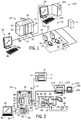
- an industrial control system 10 may include an industrial controller 12 providing generally a chassis 14 having a bus 16, such as a backplane, providing intercommunication between multiple modules 18 installed in the chassis 14.
- the modules may include, for example, a power supply module 20, a processor module 22, one or more I/O modules 24, and a network module 26.
- the network module 26, or the processor module 22, may communicate on an industrial control network 28 of a type providing connected messaging with assurances of message completion time, low latency, and lost message detection, for example, ControlNet or EtherNet/IP.
- the industrial control network 28 may join the industrial controller 12 to remote I/O modules (not shown), one or more remote motor drives 30, or additional industrial processing devices 35.
- Each motor drive 30 may communicate with corresponding electric motors 32 and position sensors 34 to provide for controlled motion of the electric motors 32 and thereby to control a portion of the associated industrial machine or process 36.
- Each motion for the controlled machine or process 36 is also referred to herein as an axis of motion.
- a machine that moves in three directions e.g., up/down, forward/reverse, and left/right
- the axes are often referred to in the coordinate system in which the machine or process 36 is controlled.
- each axis may be referred to as an "X" axis, a "Y” axis, and a “Z" axis.
- Auxiliary axes may also exist for devices such as tool changers, pallet changers, spindles, and the like that interact with the primary axes.
- each axis may be driven by a single motor 32 or multiple motors operating in tandem.
- Each motor 32 is typically controlled by a single motor drive 30.
- a single motor drive 30 may control multiple motors 32 or a single motor 32 be powered by multiple power sections.
- Each industrial processing device 35 may be a dedicated processor configured to control a particular segment of the controlled process, such as a safety controller monitoring a safety gate, safety mat, light curtain, or the like and being operational to remove power to a portion of the associated machine or process when the safety device indicates the presence of an operator in a restricted area.
- the network 28 may also join with other devices 31 on the controlled machine or process 36 such as sensors, switches, transducers, and the like that generate inputs for the industrial controller 12 corresponding to a present state of the controlled machine or process or actuators, controlled valves, status indicators, and the like that are controlled by outputs from the industrial controller 12 to achieve desired operation of the controlled machine or process.
- a configuration computer 40 may communicate with the processor module 22 and/or the motor drives 30 over the industrial control network 28 or via a dedicated communication channel 42, for example, connecting with the processor module 22.
- the configuration computer 40 may be a standard desktop or laptop computer and include a keyboard 44, display screen 46, and the like to permit the entry and display of data and the operation of a configuration program by a human operator as will be described below.
- the configuration computer 40 may be an industrial computer with the display 46, user interface, and processing portion integrated into a single housing and configured, for example, to be mounted in a control cabinet.
- An external processing device 200 is illustrated in communication with the industrial controller 12 via the network module 26 over the industrial control network 28.
- the external processing device 200 may also communicate with the processor module 22 over the industrial control network 28 or with either module via a dedicated communication channel.
- the external processing device 200 may be a generalized computing platform such as a standard desktop computer, a laptop computer, an industrial computer, or the like and include a processing unit 202, a user interface 204, such as a keyboard, a mouse, a touchpad, a touchscreen, or the like, and a display screen 206 to permit the entry and display of data and the operation of the external processing device 200 by a human operator as will be described below.
- the external processing device 200 may be implemented as a program, such as a dynamic linked library linked to the control program 54 executing in the processor module 22.
- the dynamic linked library is stored in the memory 50 of the processor module 22 and executed by the processor 48 when called by the control program 54.
- a dedicated module 18 may be provided which is inserted in one of the slots of the industrial controller 12.
- the dedicated module 18 includes memory in which the external processing routines are stored and a processor to execute the external processing routines.
- the dedicated module 18 is configured to communicate via the backplane 16 with the processor module 22.
- the processor module 22 includes a processor 48 communicating with a stored memory 50 to execute an operating system program 52 generally controlling the operation of the processor module 22, and a control program 54, the latter describing a desired control of the industrial machinery or processes 36 and typically unique to a given application of the industrial control system 10.
- the memory 50 may also include data tables (see, for example, hardware tables 88, connection tables 90, tag associations 92, and I/O tables 94 in Fig. 3 ) as used by the control program 54 and as will be described below.
- the processor module 22 also includes an inter-processor interface 51 used to integrate communication between the industrial controller 12 and external compute devices such as the external processing device 200 or additional industrial processing devices 35.
- the inter-processor interface 51 may be a dedicated control circuit, may be integrated as a series of instructions stored within the memory 50 and executed by the processor 48 of the processor module 22, or a combination thereof.
- the inter-processor interface 51 is in communication with the memory 50 and processor 48 to identify proxy execution instructions 87 which must be performed by one of the external compute devices 200 and to receive return data from the corresponding external compute device, which must be integrated with the data tables of the industrial controller 12 (see Fig. 3 ). Operation of the inter-processor interface 51 will be discussed in more detail below.
- the processor module 22 may communicate over the backplane or an inter-processor communications bus 16 with the network module 26, the latter including operating circuitry 55 (for example being a processor and a stored program and/or dedicated circuitry such as a field programmable gate array).
- the operating circuitry 55 may communicate with network interface circuitry 56, the latter providing for execution of low-level electrical protocols on the industrial control network 28.
- Similar network interface circuitry 56 may be provided in the motor drives 30 to communicate with an internal motor control processor 58 that may, for example, execute a servo controller or frequency control algorithm.
- the internal processor 58 may also communicate with a switching circuit 60 and an I/O circuit 62.
- This switching circuit 60 may provide for pulse width control or similar outputs to provide electrical power to drive coils of the motor 32, according to methods well known in the art.
- the switching circuit 60 generally includes a motor control function determining control parameters for the motor and solid-state devices and drivers that synthesize a voltage, for example one or multiple AC voltage waveforms, that is connected to the motor windings providing power to the motor that controls motor position, torque, speed or the like.
- the I/O circuits 62 receive feedback signals 64 from sensors 34 on the motors 32 (for example from encoders or the like) and may also receive other inputs, for example, from other machine-based sensors 66, for example, providing registration sensors, limit switches, optical interrupters or the like.
- the processor 58 may further communicate with a memory 68 holding firmware such as an operating system program 70 or downloaded program elements 72 of control program 54.
- the configuration computer 40 may be a standard desktop computer having a processor 74 communicating with a memory 76, the latter holding an operating system program 78 as well as various data structures and programs 80, including programs 82 used to configure the industrial control system 10.
- the computer 40 may also provide for interface circuits communicating between the processor 74, for example, and the industrial network 28 or a separate communication channel 42 to the processor module 22, as well as with the screen 46 and keyboard 44 according to methods well known in the art.
- the external processing device 200 may be a standard desktop computer having a processor 210 communicating with a memory 212, the latter holding an operating system program as well as various data structures and programs 214 for execution on the processor, including programs used to generate data used by the controlled machine or process 36.
- the external processing device 200 may also provide for interface circuits communicating between the processor 210, for example, and the industrial network 28 or a separate communication channel to the processor module 22, as well as with the display screen 206 and keyboard 204 according to methods well known in the art.
- Each additional industrial processing device 35 includes a communication interface 37 connecting the device via the industrial network 28 to the industrial controller 12.
- Each additional industrial processing device 35 also includes a processor 38 communicating with a memory 39, the latter holding various data structures and programs for execution on the processor 38, including programs receiving data from or generating data used by the controlled machine or process 36.
- the industrial processing device 35 may also provide for interface circuits communicating with a display screen or user interface according to methods well known in the art.
- the memory 50 of the processor module 22 may include data structures 88, 90, 92, 94 and programs, including a copy of the control program 54 to execute on the processor module 22.
- the data structures may include a hardware table 88 describing capabilities of the various components of the industrial control system 10, for example, including the capabilities of each motor drive 30, the I/O modules 24, and the processor module 22.
- the data structures may also include a connection list 90 describing connections between the devices (including, for example, each motor drive 30, the controller modules 18, and I/O devices 31) of the industrial control system 10 according to the conventions of connected messaging.
- each connection represents a pre-allocated portion of the industrial control network 28. These connections are normally based on data entered by the user indicating the originator and target for each connection.
- the connection list 90 may also describe a desired bandwidth of the connection, for example, defining an update rate of data transmitted over the connection.
- the data structures may further include an association list 92 associating input and output tags in the control program 54 (representing variables used in the control program 54 as reflected by data received from sensors and outputs to actuators and motors) to particular hardware elements as assigned by the user.
- Tags may similarly be defined to identify particular instructions, such as a proxy execution instruction 87, and/or status bits associated with the instruction.
- the tags associated with sensors 66 may be further associated to a motor drive 30 physically connected to the sensor 66.
- the data structures may also include various, functions, tasks or services 96 used to execute the instructions of the control program 54.
- These functions tasks or services 96 are normally stored in firmware in the processor module 22 and include functions 101 implementing instructions 86 of the control program 54 as well as services called by those functions.
- a motion planner 100 may be one of the invoked functions 101.
- the motion planner 100 when called by the functions 101, generates a motion profile of a time series of motion data (e.g. positions, velocities, or the like).
- Other functions, tasks, or services 96 include a communication service 108 handling communication between the controller and the various devices.
- These functions, tasks, or services 96 are normally part of the native environment of the processor module 22 although they may be updated periodically outside of the normal process of developing control programs.
- the data structures include the metadata defining an external computing device.
- the external processing device 200 will discuss the external processing device 200 as a particular external computing device. It is understood, however, that this embodiment is not intended to be limiting. Rather, the external computing device may be an additional industrial processing device 35, a motor drive 30, or other processing device connected to the industrial network 28. Further, it is contemplated that multiple external computing devices may be connected to the industrial network 28 where each external computing device executes responsive to separate proxy instructions 87.
- the metadata stored in the data structure identifies or defines the external processing device 200, the capacity of the external processing device 200, and how the industrial controller 12 is to communicate with the external processing device 200.
- the metadata defines which embodiment of the external processing device 200 is present in the controlled system. If the external processing device 200 is a stand-alone processing unit or implemented within a separate processing unit, the metadata defines, for example, the network 28 by which the industrial controller is connected to the planner, the communication protocol, a network address, and the like. If the external processing device 200 is embedded within the processor module 22, the metadata defines the function calls required to execute the external processing device 200 and defines resources of the processor module, such as a memory range, processing time, and the like required by the external processing device 200.
- the metadata may identify the backplane by which the module is connected, the slot number in which the module 18 is located, a dedicated communication interval by which the dedicated module may communicate with the processor module and the like.
- the metadata may also define the processing capabilities of the external processing device 200 and which of the processing capabilities are to be utilized.
- the metadata may define multiple routines present on the external processing device 200 and what data is passed between the industrial controller 12 and the external processing device 200.
- the metadata provides the configuration information required by the industrial controller 12 to communicate with the external processing device 200.
- the exemplary proxy execution instruction 180 is illustrated.
- the exemplary proxy execution instruction 180 is titled Proxy Execution.
- the Proxy Execution instruction 180 includes multiple fields 181 that are configured by a user to define the desired instruction.
- Each field 181 includes a label 182 describing the field and a user interface 184 by which the user sets one or more values for the field 181.
- the user interface 184 may take one of a number of different forms. For example, a drop-down menu may provide a user with a list of choices for the field 181.
- the user interface 181 may provide a text box to receive a user-defined setting entered via a keyboard.
- a selection button or detection of a mouse located over the user interface 184 may launch a separate configuration window in which a number of configuration parameters for the field 181 may be entered.
- the fields 181 illustrated in the Proxy Execution instruction 180 will be described herein as one exemplary instruction.
- the Proxy Execution instruction 180 will be referred to herein for convenience but is not intended to be limiting.
- one proxy execution instruction 87 may be provided by the industrial controller 12 to allow for a uniform interface to external processing devices 200.
- certain external processing devices 200 may include additional fields unique to the routine executing on the external processing device 200.
- Various other proxy execution instructions 87 with different fields may be provided within the industrial controller 12 to achieve a desired computation without deviating from the scope of the invention.
- the illustrated Proxy Execution instruction 180 includes a Processing Device field 181a in which a structure defining, for example, the type of external processing device, communication protocol, communication address, data fields, and the like. Further, the Processing Device field 181a may be used to select one of multiple external processing devices 200 if more than one external processing device 200 is provided in the controlled machine or process 36.
- the illustrated Proxy Execution instruction 180 also includes a Connection Class field 181b, defining a class of connection to be established between the industrial controller 12 and the external processing device 200.
- the class of connection is selectable according to the requirements of the external processing device 200.
- a class 1 connection provides for continuous communication between the industrial controller 12 and the external processing device 200.
- the class may be limited, for example, to a maximum of 1000 bytes of data per connection to limit the bandwidth required on the industrial network 28 for continuous communication.
- the continuous communication is repeated at a scheduled interval, where the interval may be selected at a rate equal to or faster than a scheduled task that utilizes the data provided by the external processing device 200.
- a class 3 connection provides for on-demand communication between the industrial controller 12 and the external processing device 200.
- the class 3 connection may be, for example, a remote procedure call (RPC).
- RPC remote procedure call
- the class 3 connection is not repeated at predefined intervals, but rather, is established when the proxy execution instruction 87 indicates the connection is required. Connection resources must be maintained until the data to be communicated and/or the external processing and return data is complete.
- the class 3 connection may be limited, for example, to a maximum of four kilobytes (4 KB) of data to be transmitted over each established connection.
- the class 3 connection may be utilized when the data requires fragmentation and reassembly or compression and decompression during transmission.
- the illustrated Proxy Execution instruction 180 further includes a Routine field 181c, and a Data field 181d.
- the routine field 181c may be used to identify the external processing capability present on the external processing device 200 to be executed by the instruction.
- the external processing device 200 may be a dedicated device with a single processing function.
- the external processing device 200 may include multiple processing functions and the routine field 181c identifies which of the functions is to be executed.
- the Data field 181d may be used to identify a tag, a memory address, a table, or the like in which or from which data is to be shared between the industrial controller 12 and the external processing device 200.
- a portion or all of the external processing device 200 configuration may occur during commissioning where the various information in the structure defining each external processing device 200 to be accessed outside of the control program is stored in configuration parameters accessed during execution of the control program 54.
- the illustrated Proxy Execution instruction 180 also includes a number of status bits 186.
- the status bits 186 include an enable status bit (EN), a done status bit (DN), an error status bit (ER), an in-progress status bit (IP), and an active status bit (AC).
- EN enable status bit
- DN done status bit
- ER error status bit
- IP in-progress status bit
- AC active status bit
- the Proxy Execution instruction 180 is assigned a tag identifying the instruction which is stored in the tag association table 92.
- each of the status bits includes a tag associated with the Proxy Execution instruction 180 and identifying each status bit, where the tags for the status bits are also stored in the tag association table 92.
- a proxy execution instruction 87 seamlessly integrates execution on an external computing device 200 with execution on processes internal to the industrial controller 12.
- a sequence of control instructions 86 is executed.
- control instructions 86 other than proxy execution instructions execute, these control instructions access data structures 88, 90, 92, 94 within memory 50 as required to perform the desired operation. Execution of the instructions occurs within the processor module 22.
- a proxy execution instruction 87 is inserted in the control program 54 for execution.
- the proxy execution instruction 87 may also access data structures 88, 90, 92, 94 within memory 50 as required to perform the desired operation.
- a call is made by the function 101 implementing the proxy execution instruction 87 in the hardware of the processor module 22 to execute the instruction on an external processing device 200.
- the presence and type of external processing device 200 may be entered into configuration parameters and stored in memory 50 during commissioning of the industrial controller 12.
- the presence and type of external processing device 200 may be defined in one of the user defined fields 181 of the instruction.
- the controlled machine or process 36 may include multiple external processing devices 200.
- a table may be stored in memory 50 where the table includes each of the external processing devices.
- the table may also include the metadata (as will be discussed in more detail below) corresponding to each external processing device.
- Each proxy execution instruction 87 may be configured to select one of the external processing devices from the table.
- the external processing device 200 may take one of several forms. According to a first embodiment, the external processing device 200 is a separate stand-alone processing device. According to a second embodiment, the external processing device 200 is within the processor module 22 of the industrial controller 12. According to a third embodiment, the external processing device 200 is a dedicated module 18 insertable within a slot of the chassis 14 for the industrial controller 12. An external processing device 200 references a processing unit other than the main thread of the processor module 22 executing the control program, where the external processing device is dedicated to executing one or more tasks. The external processing device 200 may be provided by the manufacturer of the industrial controller 12 or, optionally, the external processing device 200 may be provided by a third-party.
- the memory 50 of the processor module 22 stores metadata defining the external processing device 200, the capacity of the external processing device and how the industrial controller is to communicate with the external processing device.
- the metadata defines which embodiment of the external processing device 200 is present in the controlled system. If the external processing device is a stand-alone processing unit or implemented within a separate processing unit physically external to the industrial controller 12, the metadata defines, for example, the network 28 by which the industrial controller is connected to the external processing device, the communication protocol, a network address, and the like.
- the metadata defines the function calls required to execute the external processing device and defines resources of the processor module, such as a memory range, processing time, and the like required by the external processing device 200. If the external processing device is inserted as a dedicated module 18 within the chassis, the metadata may identify the backplane by which the module is connected, a dedicated communication interval by which the dedicated module 18 may communicate with the processor module and the like. In addition, the metadata may also define the processing capabilities of the external processing device 200 and which of the processing capabilities are to be utilized. For example, the metadata may define the available compute functions present on the external processing device.
- the metadata may additionally define machine data such as coordinate systems utilized by or geometry present on the machine controlled by the external processing device.
- the metadata provides the configuration information required by the industrial controller 12 to communicate with external processing device 200 and the data required by the external processing device to perform the proxy instruction 87.
- the Proxy Execution instruction 180 may be configured to interface with an external motion planner.
- the control program 54 includes multiple control instructions 86 including motion instructions.
- the control instructions may be, for example, instructions implementing timers, logic gates, flip-flops, counters, arithmetic operations, and the like expressed in a variety of different languages including relay ladder language, function block language and structured text language, all well known in the art.
- the control instructions may also include one or more motion instructions.
- the motion instructions may include commands that control movement of a motor 32, for example, between a first and second position under constraints such as maximum velocity, acceleration and jerk; jog instructions causing movement of the motor at a predetermined velocity; and coordinated motion instructions providing movement of a motor 32 in synchrony or at a predetermined ratio or other functional relationship to a second motor as determined by a cam instruction or gear instructions.
- each of these instructions implements a motion profile defining a series of motion positions and times generated by a motion planner.
- an exemplary motion instruction 141 is illustrated as a particular example of a proxy execution instruction 87.
- the exemplary motion instruction 141 is titled a coordinated move.
- the coordinated move instruction 141 defines a motion profile for at least two axes in the controlled machine or process 36 that move in tandem, causing, for example, a workpiece to travel past a fixture in tandem with a tool on the fixture acting on the workpiece.
- the two or more axes may cause a robotic arm to move in multiple axes between a first position and a second position.
- the coordinated move instruction includes multiple fields 140 that are configured by a user to define the desired motion.
- Each field 140 includes a label 142 describing the field and a user interface 144 by which the user sets one or more values for the field 140.
- the user interface 144 may take one of a number of different forms. For example, a drop-down menu may provide a user with a list of choices for the field 140.
- the user interface 144 may provide a text box to receive a user-defined setting entered via a keyboard.
- a selection button or detection of a mouse located over the user interface 144 may launch a separate configuration window in which a number of configuration parameters for the field 140 may be entered.
- the fields 140 illustrated in the coordinated move instruction 141 will be described herein as one exemplary instruction.
- the coordinated move instruction 141 will be referred to herein for convenience as one exemplary proxy execution instruction 87 but is not intended to be limiting.
- Various other proxy execution instructions with different fields may be provided within the industrial controller 12 to achieve a desired function without deviating from the scope of the invention.
- the illustrated coordinated move instruction 141 includes a Coordinate System field 140a in which the multiple axes are to operate. For example, the location of the origin of the coordinate system may be defined with respect to a reference point, such that the subsequent motion commands act on each axes in a known relationship to each other.
- the Motion Control field 140b is selected to return the status and state for the coordinated move instruction 141.
- the Path field 140c may be used to define a starting point and an ending point for the desired motion.
- the Path field 140c may further include details of the motion, for example, whether motion is to occur in the shortest point between the two points, around an exclusion zone, or the like.
- the Dynamics field 140e includes a structure defining the acceleration rate, deceleration rate, acceleration jerk rate, deceleration jerk rate, maximum speed, and the like.
- the Lock fields 140f i.e., Lock Position and Lock Direction
- the Planner field 140d may be used to define whether the motion instruction is to be executed via an internal motion planner 100 within the industrial controller 12 or an external processing device 200 in communication with the industrial controller 12.
- the Planner field 140d may include a structure defining, for example, the type of external processing device, communication protocol, communication address, data fields, and the like. Further, the Planner field 140d may be used to select one of multiple external processing devices 200 if more than one external processing device 200 is provided in the controlled machine or process 36. Optionally, it is contemplated, that external processing device 200 configuration may occur during commissioning where the various information in the structure defining each external processing device 200 may be accessed outside of the control program and stored in configuration parameters accessed during execution of the control program 54.
- the illustrated coordinated move instruction 141 also includes a number of status bits 146.
- the status bits 146 include an enable status bit (EN), a done status bit (DN), an error status bit (ER), an in-progress status bit (IP), an active status bit (AC), and a process complete status bit (PC).
- the coordinated move instruction 141 is assigned a tag identifying the instruction which is stored in the tag association table 92.
- each of the status bits includes a tag associated with the coordinated move instruction 141 and identifying each status bit, where the tags for the status bits are also stored in the tag association table 92.
- the external processing device 200 may be an external motion planner as defined in the Planner field 140d of the coordinated move instruction 141.
- the coordinated move instruction 141 executes a function 101 on the industrial controller 12 that sends a motion profile 120 to the external motion planner 200 via the inter-processor interface 51.
- the motion profile 120 represents a desired move command for one or more axes in the controlled machine or process.
- the inter-processor interface 51 may also transmit data required for execution of the move command, such as parameters stored in memory 50 of the industrial controller, to the external motion planner 200.
- the external motion planner 200 based on parameters and the profile 120 passed from the inter-processor interface 51, processes the motion profile 120 and generates a series of motion data 110 according to the motion planning routines executing on the external planner.
- the series of motion data 110 generated by the external motion planner 200 is transmitted back to the industrial controller 12.
- the industrial controller 12 and an internal motion planner 100 executing on the industrial controller, utilizes the series of motion data 110 from the external motion planner 200 as one of multiple potential sources of motion commands to each axis and combines this series of motion data 110 with any additional series of motion data 110 present for an axis to control operation of the axis.
- the processor module transmits the combined series of motion data 110 output from the internal motion planner 100 to the motor drive(s) 30 corresponding to the axis(axes) for which motion is desired over the industrial network 28.
- an external motion planner may be integrated with an internal motion planner to achieve desired operation of the controlled axes.
- the industrial controller 12 may maintain a motion state machine 300 for each axis corresponding to a current state of operation of the axis.
- a motion state machine 300 for one axis is illustrated.
- the motion state machine 300 includes an initial state (State 0) 302 during which the state machine 300 is initialized such as when power is cycled on the industrial controller 12 or on the motor drive 30 corresponding to that axis. After initialization, the state machine 300 transitions to a wait state (State 1) 304.
- State 1 wait state
- the state machine 300 may transition through several different states during the commanded motion.
- a simple motion profile may command an axis, and therefore, the motor 32 associated with the axis, to accelerate from a stopped condition to a constant speed, travel at the constant speed, and decelerate back to a stopped condition.
- the state machine 300 transitions through the acceleration state (State 2) 306, run state (State 3) 308, and the deceleration state (State 4).
- the axis may be required to change speed during a move and transition back and forth between the acceleration, run, and/or deceleration states.
- the axis Upon completion of the commanded motion, the axis returns to the wait state 304.
- the industrial controller 12 may be configured to execute a fault handler routine for the axis when the state machine enters the fault state 316.
- the fault handler routine may determine whether an immediate stop, a controlled stop, or a message is posted for an operator while motion is allowed to proceed. If the fault handler routine provides for recovery after the fault, the state machine 300 may return to acceleration state 306, run state 308, or the deceleration state 310. Optionally, if the fault handler routine provides for an immediate or controlled stop, the state machine 300 remains in the fault state 316 until a fault reset occurs, returning the state machine 300 to the wait state 304.
- an external motion planner on the external processing device 200 is integrated with an internal motion planner 100 and the state machine 300 managed by the industrial controller 12.
- a proxy execution instruction 87 by the external processing device 200 it is contemplated that a second motion instruction may be executed by the control program 54, where the second motion instruction is intended to be implemented by the internal motion planner 100 (see Fig. 7 ).
- the industrial controller 12 may receive an input signal at an I/O module 24, where the input signal indicates that the coordinated move instruction 141 should be altered or overridden.
- Integration of a function on the external processing device 200 with the state machine 300 executing on the industrial controller 12 permits subsequent motion commands and/or input signals requesting motion for an axis to be processed while the first motion instruction is still executing, thereby increasing the flexibility of control for each axis.
- the state machine 300 may enter the abort state (State 5) 312.
- the abort state 312 may include one or more routines to handle an immediate stop or a controlled stop of the axis.
- the abort state 312 may cause a revised motion profile to be transmitted to the external processing device 200 responsive to the input or second motion command such that the immediate or controlled stop is achieved.
- Such operation may be desired, for example, if the control program 54 detects a problem with a workpiece during execution of the initial coordinated move instruction 141.
- the control program may require that the workpiece be moved to an inspection station rather than continue on its original trajectory and issues a new coordinated move instruction 141 to the external processing device 200.
- the industrial controller 12 may receive an input signal indicating an access gate has been opened or a light curtain has been broken, indicating the presence of a technician or operator within a protected region.
- the industrial controller 12 may issue an immediate or controlled stop, aborting the original coordinated move instruction 141.
- the state machine 300 may also inhibit the original instruction.
- a second motion instruction may, for example, command a jog of an axis from a pushbutton or other operator interface.
- the internal motion planner 100 may generate a series of motion data 110 for the motor drive 30 corresponding to the commanded jog.
- the internal motion planner 100 may, in turn, inhibit the series of motion data 110 generated by the external processing device 200 until the jog command is removed. Once the jog command is removed, the internal motion planner 100 may cause the motion profile to the external processing device 200 to be updated.
- the external processing device 200 may monitor the position feedback signals from the axis and continually update the series of motion data 110 during the jog command for the axis to reach the original desired location.
- the state machine 300 leaves the inhibit state 314 and returns to the acceleration state 306, run state 308, or deceleration state 310 according to the commanded motion from the external processing device 200.
- the above described state machine 300 is exemplary and is not intended to be limiting. It is contemplated that the state machine 300 may include fewer states or additional states than those illustrated and may similarly include fewer or additional transitions between states according to the application requirements.
- the coordinated move instruction 141 includes a number of status bits 146.
- the status bits 146 are updated according to the present operation of the axis or axes to be controlled by the coordinated move instruction 141.
- the enable status bit (EN) is set.
- the active status bit (AC) is set.
- the status bits 146 for the coordinated move instruction 141 are similarly set when the external processing device 200 is executing a proxy execution instruction 87.
- the external processing device 200 executes one or more motion control routines 220 on the processor 210 in the external processing device 200.
- the motion control routines generate similar status bits to those set in the coordinated move instruction 141.
- various status bits generated by the external processing device 200 are similarly transmitted from the external processing device 200 to the industrial controller 12.
- the inter-processor interface 51 receives the status bits generated by the external processing device 200 and sets the corresponding status bits for the coordinated move instruction 141. As previously discussed, a tag is assigned to each of the status bits 146 for the coordinated move instruction 141 and stored in a tag association table 92.
- the tag association table 92 may further include a tag associated with each of the status bits generated by the external processing device 200 and/or an association between the status bits generated by the external processing device 200 and the status bits for the coordinated move instruction 141.
- the inter-processor interface 51 identifies the corresponding status bit for the coordinated move instruction 141 via the definitions in the tag association table 92. The inter-processor interface 51 then sets or resets the status bits 146 for the motion instruction according to the values of the corresponding status bits generated by the external processing device 200.
- the coordinated move instruction 141 executes within the control program 54 as if the internal motion planner 100 rather than the external processing device 200 were processing the motion profile.
- the industrial controller 12 is able to integrate the external motion control routines 220 within the state machine 300 for each axis and to have complete knowledge of the controlled axis throughout execution of the desired motion profile.
- the industrial controller 12 has knowledge, for example, of the current position, the commanded position, and the current operating status of the axis.
- prior art systems only passed the move command to the external processing device 200 and waited either for a predefined time in which the move was expected to complete or for a response from the external motion planner indicating that the motion was complete.
- the integration of the external motion planner further allows other systems, such as safety systems, jog functions, leader/follower functions, gearing functions, axis offsets, and the like that are already implemented within the industrial controller 12 to be readily applied to the external processing device 200.
- These internal functions are executed by the internal motion planner 100, generating a first time series of motion data for each axis, and the motion profile is processed by the external processing device 200, generating a second time series of motion data, where the two time series of motion data are summed together to result in a modified, or combined, time series of motion data to be output to the motor drive 30 for each axis.
- references to "a microprocessor” and “a processor” or “the microprocessor” and “the processor,” can be understood to include one or more microprocessors that can communicate in a stand-alone and/or a distributed environment(s), and can thus be configured to communicate via wired or wireless communications with other processors, where such one or more processor can be configured to operate on one or more processor-controlled devices that can be similar or different devices.
- references to memory can include one or more processor-readable and accessible memory elements and/or components that can be internal to the processor-controlled device, external to the processor-controlled device, and can be accessed via a wired or wireless network.
Landscapes
- Engineering & Computer Science (AREA)
- Physics & Mathematics (AREA)
- General Physics & Mathematics (AREA)
- Automation & Control Theory (AREA)
- Theoretical Computer Science (AREA)
- General Engineering & Computer Science (AREA)
- Manufacturing & Machinery (AREA)
- Quality & Reliability (AREA)
- Programmable Controllers (AREA)
Abstract
Description
- This application claims priority to
U.S. Provisional Application Ser. No. 62/760,568, filed November 13, 2018 - The subject matter disclosed herein relates to integrating external processing resources into industrial control systems and in particular to a method and system of managing shared resources between internal and external processing routines.
- Industrial controllers are specialized computer systems used for the control of industrial processes or machinery, for example, in a factory environment. Generally, an industrial controller executes a stored control program that reads inputs from a variety of sensors associated with the controlled process or machine and, sensing the conditions of the process or machine and based on those inputs and a stored control program, calculates a set of outputs used to control actuators controlling the process or machine. Special control languages, such as "relay ladder logic" are normally used to facilitate programming of the device. Under the direction of the stored program, a processor of the industrial controller periodically examines the state of input devices and updates the state of output devices. In order to ensure predictable control of a machine or process, the control program must be highly reliable and deterministic, that is, executing at well-defined time periods.
- Industrial controllers differ from conventional computers in a number of ways. Physically, they are constructed to be substantially more robust against shock and damage and to better resist external contaminants and extreme environmental conditions than conventional computers. The processors and operating systems are optimized for real-time control and are programmed with languages designed to permit rapid development of control programs tailored to a constantly varying set of machine control or process control applications.
- Industrial controllers are customizable according to an application's requirements. Commonly, an industrial controller includes a chassis with a number of slots into which modules may be inserted. The modules provide varying functions and/or connections for the industrial controller including, for example, network communications, analog or digital inputs and outputs, counter modules, and the like. The modules receive input signals from sensors, contacts, switches, and other devices on a controlled machine or process and pass the input signals to a processor module. The processor module executes a control program where it receives the input signals and sets output signals on other modules to control actuators, valves, solenoids, and the like on the controlled machine or process responsive to the received inputs. A programmer generates the control program to achieve desired operation of the controlled machine or process.
- In certain applications, the programming requirements may exceed the computational abilities of the processor module, and it is necessary to provide an external computational device. In other applications, the programming requirements may fall within the computational abilities of the processor module, but other computational devices may be present in the control system that are better suited than the processor module to execute a portion of the control program. In either application, one or more external computational devices may be used to perform a desired computation and provide a result of the computation to the industrial controller. Using an external computation device, however, is not without certain drawbacks. The industrial controller and the external computational device each execute asynchronously from each other based on their own internal clock. The external computational device requires information, such as internal status flags, the state of certain inputs or outputs, and the like and may share certain tags to which both the industrial controller and the external computational device have access. Data written to or read from the shared tags must be managed such that one controller does not unintentionally overwrite data from the other controller.
- Thus, it would be desirable to provide an improved system for managing execution of a control program on multiple processing devices.
- It would also be desirable to integrally manage execution of the portions of the control program on each of the processing devices where details of the execution of the portions of the control program on each of the processing devices is transparent to the programmer.
- The subject matter disclosed herein describes an improved system for managing execution of a control program on multiple processing devices. A control program is stored in memory and executable on a first processor in an industrial controller. The control program includes control instructions executed solely on the first processor and proxy instructions configured to launch execution of a function on an external processing device. It is contemplated that the external processing device may be a computing unit that is physically separate from the industrial controller or, optionally, the external processing unit may be a dedicated module inserted within a chassis of the industrial controller. According to still another embodiment, the external processing unit may be a dedicated function executing in the same processor but on a separate thread or core in parallel to the control program.
- An inter-processor interface is configured to manage execution of the portions of the control program executing on each of the processing devices such that details of the execution of the portions of the control program on each of the processing devices is transparent to the programmer. The inter-processor interface establishes a communication connection between the processor and the external processing device. Details of the connection may be stored, for example, in a table defining external processing devices connected to the industrial controller. The table may include metadata defining, for example, a protocol for communication, a port assignment, addresses, and the like. The inter-processor interface may also transmit data from data tables in memory of the industrial controller to the external processing devices for use during execution of the proxy instruction. The inter-processor interface is further configured to manage status bits of the proxy instruction, as required, and to receive data back from the external processing device and to update data in the data tables as required. It is further contemplated that, if required, the inter-processor interface may manage access to the data from other control instructions in the control program during execution of the proxy instruction. Thus, execution of the proxy instruction is integrated with execution of other control instructions in the control program and details of the execution are transparent to a programmer. Rather, the programmer simply identifies a function, data required for the function, and an external processing device on which the function is intended to execute.
- According to one embodiment of the invention, an industrial controller configured to coordinate execution of an external processing device with the industrial controller is disclosed The industrial controller includes a memory device, a processor, and an inter-processor interface. The memory device is operative to store a control program and at least one data structure, and the processor is operative to execute the control program. The control program includes at least one proxy instruction to be executed on an external processing device. The inter-processor interface is operative to integrate execution of the at least one proxy instruction on the external processing device with execution of the control program on the processor. The at least one proxy instruction defines data from the at least one data structure required for execution of the corresponding proxy instruction. The inter-processor interface reads the data from the at least one data structure and transmits the data to the external processing device. The inter-processor interface receives a response from the external processing device indicating a status of processing the at least one proxy instruction.
- According to another embodiment of the invention, a method of coordinating execution of an external processing device with an industrial controller is disclosed. Multiple control instructions are executed on a processor of an industrial controller, where the control instructions access data from at least one data structure stored in memory of the industrial controller. At least one proxy instruction is executed on the processor of the industrial controller, and the at least one proxy instruction defines at least one function to be executed on an external processing device. The at least one proxy instruction defines shared data from the at least one data structure, and the shared data is accessed by at least one of the control instructions and is required for execution of the at least one proxy instruction. The shared data is read with an inter-processor interface executing on the industrial controller and transmitted to the external processing device with the inter-processor interface. A response from the external processing device, indicating a status of executing the at least one function defined by the at least one proxy instruction, is received at the inter-processor interface.
- According to still another embodiment of the invention, a processor module for an industrial controller configured to coordinate execution of an external processing device with the industrial controller is disclosed. The processor module includes a memory and a processor. The memory is operative to store a control program and at least one data structure, and the processor is operative to execute the control program. The control program includes a plurality of control instructions and at least one proxy instruction, where the at least one proxy instruction defines data from the at least one data structure required for execution of the corresponding proxy instruction and the at least one proxy instruction defines at least one function to be executed on an external processing device. The processor is further operative to read the data from the at least one data structure, transmit the data to the external processing device, and receive a response from the external processing device indicating a status of processing the at least one proxy instruction.
- These and other advantages and features of the invention will become apparent to those skilled in the art from the detailed description and the accompanying drawings. It should be understood, however, that the detailed description and accompanying drawings, while indicating preferred embodiments of the present invention, are given by way of illustration and not of limitation. Many changes and modifications may be made within the scope of the present invention without departing from the spirit thereof, and the invention includes all such modifications.
- Various exemplary embodiments of the subject matter disclosed herein are illustrated in the accompanying drawings in which like reference numerals represent like parts throughout, and in which:
-
FIG. 1 is a simplified perspective view of an exemplary industrial control system having an industrial controller communicating with multiple external processing devices over a communication network; -
FIG. 2 is a block diagram of the components of the industrial control system ofFig. 1 showing multiple interacting processors of various components executing stored programs in a distributed fashion; -
FIG. 3 is a block diagram representation of a control program and data structures used by the industrial controller ofFig. 1 ; -
FIG. 4 is an exemplary proxy execution instruction executed by the control program ofFig. 3 ; -
FIG. 5 is an exemplary motion instruction serving as an exemplary proxy execution instruction executed by the control program ofFig. 3 ; -
FIG. 6 is a flow diagram illustrating an exemplary state machine implemented in the industrial controller for one axis of the controlled machine or process; and -
FIG. 7 is a block diagram representation of the industrial controller and one motor drive illustrating an external motion planner and motion instructions according to one embodiment of the invention. - In describing the various embodiments of the invention which are illustrated in the drawings, specific terminology will be resorted to for the sake of clarity. However, it is not intended that the invention be limited to the specific terms so selected and it is understood that each specific term includes all technical equivalents which operate in a similar manner to accomplish a similar purpose. For example, the word "connected," "attached," or terms similar thereto are often used. They are not limited to direct connection but include connection through other elements where such connection is recognized as being equivalent by those skilled in the art.
- The various features and advantageous details of the subject matter disclosed herein are explained more fully with reference to the non-limiting embodiments described in detail in the following description.
- Turning initially to
Fig. 1 , anindustrial control system 10 may include anindustrial controller 12 providing generally achassis 14 having abus 16, such as a backplane, providing intercommunication betweenmultiple modules 18 installed in thechassis 14. The modules may include, for example, apower supply module 20, aprocessor module 22, one or more I/O modules 24, and anetwork module 26. Thenetwork module 26, or theprocessor module 22, may communicate on anindustrial control network 28 of a type providing connected messaging with assurances of message completion time, low latency, and lost message detection, for example, ControlNet or EtherNet/IP. - The
industrial control network 28 may join theindustrial controller 12 to remote I/O modules (not shown), one or more remote motor drives 30, or additionalindustrial processing devices 35. Eachmotor drive 30 may communicate with correspondingelectric motors 32 andposition sensors 34 to provide for controlled motion of theelectric motors 32 and thereby to control a portion of the associated industrial machine orprocess 36. Each motion for the controlled machine orprocess 36 is also referred to herein as an axis of motion. For example, a machine that moves in three directions (e.g., up/down, forward/reverse, and left/right) has three axes. The axes are often referred to in the coordinate system in which the machine orprocess 36 is controlled. Therefore, for a machine or process controlled in the Cartesian Coordinate System, the axes may be referred to as an "X" axis, a "Y" axis, and a "Z" axis. Auxiliary axes may also exist for devices such as tool changers, pallet changers, spindles, and the like that interact with the primary axes. Further, each axis may be driven by asingle motor 32 or multiple motors operating in tandem. Eachmotor 32 is typically controlled by asingle motor drive 30. However, it is contemplated that asingle motor drive 30 may controlmultiple motors 32 or asingle motor 32 be powered by multiple power sections. Eachindustrial processing device 35 may be a dedicated processor configured to control a particular segment of the controlled process, such as a safety controller monitoring a safety gate, safety mat, light curtain, or the like and being operational to remove power to a portion of the associated machine or process when the safety device indicates the presence of an operator in a restricted area. Thenetwork 28 may also join withother devices 31 on the controlled machine orprocess 36 such as sensors, switches, transducers, and the like that generate inputs for theindustrial controller 12 corresponding to a present state of the controlled machine or process or actuators, controlled valves, status indicators, and the like that are controlled by outputs from theindustrial controller 12 to achieve desired operation of the controlled machine or process. - A
configuration computer 40 may communicate with theprocessor module 22 and/or the motor drives 30 over theindustrial control network 28 or via adedicated communication channel 42, for example, connecting with theprocessor module 22. Theconfiguration computer 40 may be a standard desktop or laptop computer and include akeyboard 44,display screen 46, and the like to permit the entry and display of data and the operation of a configuration program by a human operator as will be described below. Optionally, theconfiguration computer 40 may be an industrial computer with thedisplay 46, user interface, and processing portion integrated into a single housing and configured, for example, to be mounted in a control cabinet. - An
external processing device 200 is illustrated in communication with theindustrial controller 12 via thenetwork module 26 over theindustrial control network 28. Theexternal processing device 200 may also communicate with theprocessor module 22 over theindustrial control network 28 or with either module via a dedicated communication channel. Theexternal processing device 200 may be a generalized computing platform such as a standard desktop computer, a laptop computer, an industrial computer, or the like and include aprocessing unit 202, auser interface 204, such as a keyboard, a mouse, a touchpad, a touchscreen, or the like, and adisplay screen 206 to permit the entry and display of data and the operation of theexternal processing device 200 by a human operator as will be described below. - According to another embodiment of the invention, the
external processing device 200 may be implemented as a program, such as a dynamic linked library linked to thecontrol program 54 executing in theprocessor module 22. The dynamic linked library is stored in thememory 50 of theprocessor module 22 and executed by theprocessor 48 when called by thecontrol program 54. According to still another embodiment of the invention, adedicated module 18 may be provided which is inserted in one of the slots of theindustrial controller 12. Thededicated module 18 includes memory in which the external processing routines are stored and a processor to execute the external processing routines. Thededicated module 18 is configured to communicate via thebackplane 16 with theprocessor module 22. - Referring now to
Fig. 2 , theprocessor module 22 includes aprocessor 48 communicating with a storedmemory 50 to execute anoperating system program 52 generally controlling the operation of theprocessor module 22, and acontrol program 54, the latter describing a desired control of the industrial machinery or processes 36 and typically unique to a given application of theindustrial control system 10. Thememory 50 may also include data tables (see, for example, hardware tables 88, connection tables 90,tag associations 92, and I/O tables 94 inFig. 3 ) as used by thecontrol program 54 and as will be described below. - The
processor module 22 also includes aninter-processor interface 51 used to integrate communication between theindustrial controller 12 and external compute devices such as theexternal processing device 200 or additionalindustrial processing devices 35. Although illustrated as a separate module, theinter-processor interface 51 may be a dedicated control circuit, may be integrated as a series of instructions stored within thememory 50 and executed by theprocessor 48 of theprocessor module 22, or a combination thereof. Theinter-processor interface 51 is in communication with thememory 50 andprocessor 48 to identifyproxy execution instructions 87 which must be performed by one of theexternal compute devices 200 and to receive return data from the corresponding external compute device, which must be integrated with the data tables of the industrial controller 12 (seeFig. 3 ). Operation of theinter-processor interface 51 will be discussed in more detail below. - The
processor module 22 may communicate over the backplane or aninter-processor communications bus 16 with thenetwork module 26, the latter including operating circuitry 55 (for example being a processor and a stored program and/or dedicated circuitry such as a field programmable gate array). The operatingcircuitry 55 may communicate withnetwork interface circuitry 56, the latter providing for execution of low-level electrical protocols on theindustrial control network 28. - Similar
network interface circuitry 56 may be provided in the motor drives 30 to communicate with an internalmotor control processor 58 that may, for example, execute a servo controller or frequency control algorithm. Theinternal processor 58 may also communicate with a switchingcircuit 60 and an I/O circuit 62. This switchingcircuit 60 may provide for pulse width control or similar outputs to provide electrical power to drive coils of themotor 32, according to methods well known in the art. The switchingcircuit 60 generally includes a motor control function determining control parameters for the motor and solid-state devices and drivers that synthesize a voltage, for example one or multiple AC voltage waveforms, that is connected to the motor windings providing power to the motor that controls motor position, torque, speed or the like. The I/O circuits 62 receive feedback signals 64 fromsensors 34 on the motors 32 (for example from encoders or the like) and may also receive other inputs, for example, from other machine-basedsensors 66, for example, providing registration sensors, limit switches, optical interrupters or the like. Theprocessor 58 may further communicate with amemory 68 holding firmware such as anoperating system program 70 or downloadedprogram elements 72 ofcontrol program 54. - As noted above, the
configuration computer 40 may be a standard desktop computer having aprocessor 74 communicating with amemory 76, the latter holding anoperating system program 78 as well as various data structures andprograms 80, includingprograms 82 used to configure theindustrial control system 10. Thecomputer 40 may also provide for interface circuits communicating between theprocessor 74, for example, and theindustrial network 28 or aseparate communication channel 42 to theprocessor module 22, as well as with thescreen 46 andkeyboard 44 according to methods well known in the art. - The
external processing device 200 may be a standard desktop computer having aprocessor 210 communicating with amemory 212, the latter holding an operating system program as well as various data structures andprograms 214 for execution on the processor, including programs used to generate data used by the controlled machine orprocess 36. Theexternal processing device 200 may also provide for interface circuits communicating between theprocessor 210, for example, and theindustrial network 28 or a separate communication channel to theprocessor module 22, as well as with thedisplay screen 206 andkeyboard 204 according to methods well known in the art. - Each additional
industrial processing device 35 includes acommunication interface 37 connecting the device via theindustrial network 28 to theindustrial controller 12. Each additionalindustrial processing device 35 also includes aprocessor 38 communicating with amemory 39, the latter holding various data structures and programs for execution on theprocessor 38, including programs receiving data from or generating data used by the controlled machine orprocess 36. Theindustrial processing device 35 may also provide for interface circuits communicating with a display screen or user interface according to methods well known in the art. - Referring now to
Fig. 3 , thememory 50 of theprocessor module 22 may includedata structures control program 54 to execute on theprocessor module 22. The data structures may include a hardware table 88 describing capabilities of the various components of theindustrial control system 10, for example, including the capabilities of eachmotor drive 30, the I/O modules 24, and theprocessor module 22. - The data structures may also include a
connection list 90 describing connections between the devices (including, for example, eachmotor drive 30, thecontroller modules 18, and I/O devices 31) of theindustrial control system 10 according to the conventions of connected messaging. Generally each connection represents a pre-allocated portion of theindustrial control network 28. These connections are normally based on data entered by the user indicating the originator and target for each connection. Theconnection list 90 may also describe a desired bandwidth of the connection, for example, defining an update rate of data transmitted over the connection. - The data structures may further include an
association list 92 associating input and output tags in the control program 54 (representing variables used in thecontrol program 54 as reflected by data received from sensors and outputs to actuators and motors) to particular hardware elements as assigned by the user. Tags may similarly be defined to identify particular instructions, such as aproxy execution instruction 87, and/or status bits associated with the instruction. Thus, for example, the tags associated with sensors 66 (shown inFig. 2 ) may be further associated to amotor drive 30 physically connected to thesensor 66. - The data structures may also include various, functions, tasks or
services 96 used to execute the instructions of thecontrol program 54. These functions tasks orservices 96 are normally stored in firmware in theprocessor module 22 and include functions 101 implementinginstructions 86 of thecontrol program 54 as well as services called by those functions. For example, amotion planner 100 may be one of the invoked functions 101. Themotion planner 100, when called by the functions 101, generates a motion profile of a time series of motion data (e.g. positions, velocities, or the like). Other functions, tasks, orservices 96 include acommunication service 108 handling communication between the controller and the various devices. These functions, tasks, orservices 96 are normally part of the native environment of theprocessor module 22 although they may be updated periodically outside of the normal process of developing control programs. - According to one aspect of the invention, the data structures include the metadata defining an external computing device. For convenience, the application will discuss the
external processing device 200 as a particular external computing device. It is understood, however, that this embodiment is not intended to be limiting. Rather, the external computing device may be an additionalindustrial processing device 35, amotor drive 30, or other processing device connected to theindustrial network 28. Further, it is contemplated that multiple external computing devices may be connected to theindustrial network 28 where each external computing device executes responsive toseparate proxy instructions 87. - The metadata stored in the data structure identifies or defines the
external processing device 200, the capacity of theexternal processing device 200, and how theindustrial controller 12 is to communicate with theexternal processing device 200. The metadata defines which embodiment of theexternal processing device 200 is present in the controlled system. If theexternal processing device 200 is a stand-alone processing unit or implemented within a separate processing unit, the metadata defines, for example, thenetwork 28 by which the industrial controller is connected to the planner, the communication protocol, a network address, and the like. If theexternal processing device 200 is embedded within theprocessor module 22, the metadata defines the function calls required to execute theexternal processing device 200 and defines resources of the processor module, such as a memory range, processing time, and the like required by theexternal processing device 200. If theexternal processing device 200 is inserted as adedicated module 18 within the chassis, the metadata may identify the backplane by which the module is connected, the slot number in which themodule 18 is located, a dedicated communication interval by which the dedicated module may communicate with the processor module and the like. In addition, the metadata may also define the processing capabilities of theexternal processing device 200 and which of the processing capabilities are to be utilized. For example, the metadata may define multiple routines present on theexternal processing device 200 and what data is passed between theindustrial controller 12 and theexternal processing device 200. In general, the metadata provides the configuration information required by theindustrial controller 12 to communicate with theexternal processing device 200. - One or more
proxy execution instructions 87 are defined within theindustrial controller 12. With reference toFig. 4 , an exemplaryproxy execution instruction 180 is illustrated. The exemplaryproxy execution instruction 180 is titled Proxy Execution. TheProxy Execution instruction 180 includes multiple fields 181 that are configured by a user to define the desired instruction. Each field 181 includes alabel 182 describing the field and auser interface 184 by which the user sets one or more values for the field 181. It is contemplated that theuser interface 184 may take one of a number of different forms. For example, a drop-down menu may provide a user with a list of choices for the field 181. Optionally, the user interface 181 may provide a text box to receive a user-defined setting entered via a keyboard. According to still another option, a selection button or detection of a mouse located over theuser interface 184 may launch a separate configuration window in which a number of configuration parameters for the field 181 may be entered. - The fields 181 illustrated in the
Proxy Execution instruction 180 will be described herein as one exemplary instruction. TheProxy Execution instruction 180 will be referred to herein for convenience but is not intended to be limiting. Preferably, oneproxy execution instruction 87 may be provided by theindustrial controller 12 to allow for a uniform interface toexternal processing devices 200. However, it is contemplated that certainexternal processing devices 200 may include additional fields unique to the routine executing on theexternal processing device 200. Various otherproxy execution instructions 87 with different fields may be provided within theindustrial controller 12 to achieve a desired computation without deviating from the scope of the invention. The illustratedProxy Execution instruction 180 includes aProcessing Device field 181a in which a structure defining, for example, the type of external processing device, communication protocol, communication address, data fields, and the like. Further, theProcessing Device field 181a may be used to select one of multipleexternal processing devices 200 if more than oneexternal processing device 200 is provided in the controlled machine orprocess 36. - The illustrated
Proxy Execution instruction 180 also includes aConnection Class field 181b, defining a class of connection to be established between theindustrial controller 12 and theexternal processing device 200. The class of connection is selectable according to the requirements of theexternal processing device 200. Aclass 1 connection provides for continuous communication between theindustrial controller 12 and theexternal processing device 200. The class may be limited, for example, to a maximum of 1000 bytes of data per connection to limit the bandwidth required on theindustrial network 28 for continuous communication. The continuous communication is repeated at a scheduled interval, where the interval may be selected at a rate equal to or faster than a scheduled task that utilizes the data provided by theexternal processing device 200. - A
class 3 connection provides for on-demand communication between theindustrial controller 12 and theexternal processing device 200. Theclass 3 connection may be, for example, a remote procedure call (RPC). Theclass 3 connection is not repeated at predefined intervals, but rather, is established when theproxy execution instruction 87 indicates the connection is required. Connection resources must be maintained until the data to be communicated and/or the external processing and return data is complete. Theclass 3 connection may be limited, for example, to a maximum of four kilobytes (4 KB) of data to be transmitted over each established connection. Theclass 3 connection may be utilized when the data requires fragmentation and reassembly or compression and decompression during transmission. - The illustrated
Proxy Execution instruction 180 further includes aRoutine field 181c, and aData field 181d. Theroutine field 181c may be used to identify the external processing capability present on theexternal processing device 200 to be executed by the instruction. In certain applications, theexternal processing device 200 may be a dedicated device with a single processing function. In other applications, theexternal processing device 200 may include multiple processing functions and theroutine field 181c identifies which of the functions is to be executed. TheData field 181d may be used to identify a tag, a memory address, a table, or the like in which or from which data is to be shared between theindustrial controller 12 and theexternal processing device 200. - It is contemplated, that a portion or all of the
external processing device 200 configuration may occur during commissioning where the various information in the structure defining eachexternal processing device 200 to be accessed outside of the control program is stored in configuration parameters accessed during execution of thecontrol program 54. - The illustrated
Proxy Execution instruction 180 also includes a number ofstatus bits 186. According to the illustrated instruction, thestatus bits 186 include an enable status bit (EN), a done status bit (DN), an error status bit (ER), an in-progress status bit (IP), and an active status bit (AC). TheProxy Execution instruction 180 is assigned a tag identifying the instruction which is stored in the tag association table 92. Similarly, each of the status bits includes a tag associated with theProxy Execution instruction 180 and identifying each status bit, where the tags for the status bits are also stored in the tag association table 92. - In operation, a
proxy execution instruction 87 seamlessly integrates execution on anexternal computing device 200 with execution on processes internal to theindustrial controller 12. During execution of acontrol program 54, as shown inFig. 3 , a sequence ofcontrol instructions 86 is executed. Ascontrol instructions 86 other than proxy execution instructions execute, these control instructionsaccess data structures memory 50 as required to perform the desired operation. Execution of the instructions occurs within theprocessor module 22. - When required according to the application requirements, a
proxy execution instruction 87 is inserted in thecontrol program 54 for execution. Theproxy execution instruction 87 may also accessdata structures memory 50 as required to perform the desired operation. During execution of theproxy execution instruction 87, a call is made by the function 101 implementing theproxy execution instruction 87 in the hardware of theprocessor module 22 to execute the instruction on anexternal processing device 200. The presence and type ofexternal processing device 200 may be entered into configuration parameters and stored inmemory 50 during commissioning of theindustrial controller 12. Optionally, the presence and type ofexternal processing device 200 may be defined in one of the user defined fields 181 of the instruction. According to still another aspect of the invention, the controlled machine orprocess 36 may include multipleexternal processing devices 200. A table may be stored inmemory 50 where the table includes each of the external processing devices. The table may also include the metadata (as will be discussed in more detail below) corresponding to each external processing device. Eachproxy execution instruction 87 may be configured to select one of the external processing devices from the table. - As previously discussed, the
external processing device 200 may take one of several forms. According to a first embodiment, theexternal processing device 200 is a separate stand-alone processing device. According to a second embodiment, theexternal processing device 200 is within theprocessor module 22 of theindustrial controller 12. According to a third embodiment, theexternal processing device 200 is adedicated module 18 insertable within a slot of thechassis 14 for theindustrial controller 12. Anexternal processing device 200 references a processing unit other than the main thread of theprocessor module 22 executing the control program, where the external processing device is dedicated to executing one or more tasks. Theexternal processing device 200 may be provided by the manufacturer of theindustrial controller 12 or, optionally, theexternal processing device 200 may be provided by a third-party. - Accordingly, the
memory 50 of theprocessor module 22 stores metadata defining theexternal processing device 200, the capacity of the external processing device and how the industrial controller is to communicate with the external processing device. The metadata defines which embodiment of theexternal processing device 200 is present in the controlled system. If the external processing device is a stand-alone processing unit or implemented within a separate processing unit physically external to theindustrial controller 12, the metadata defines, for example, thenetwork 28 by which the industrial controller is connected to the external processing device, the communication protocol, a network address, and the like. If the external processing device is embedded within theprocessor module 22 and executes, for example, on a processing thread or core in parallel to a processing thread or core executing the control program, the metadata defines the function calls required to execute the external processing device and defines resources of the processor module, such as a memory range, processing time, and the like required by theexternal processing device 200. If the external processing device is inserted as adedicated module 18 within the chassis, the metadata may identify the backplane by which the module is connected, a dedicated communication interval by which thededicated module 18 may communicate with the processor module and the like. In addition, the metadata may also define the processing capabilities of theexternal processing device 200 and which of the processing capabilities are to be utilized. For example, the metadata may define the available compute functions present on the external processing device. The metadata may additionally define machine data such as coordinate systems utilized by or geometry present on the machine controlled by the external processing device. In general, the metadata provides the configuration information required by theindustrial controller 12 to communicate withexternal processing device 200 and the data required by the external processing device to perform theproxy instruction 87. - According to one embodiment of the invention, the
Proxy Execution instruction 180 may be configured to interface with an external motion planner. Thecontrol program 54 includesmultiple control instructions 86 including motion instructions. Generally, the control instructions may be, for example, instructions implementing timers, logic gates, flip-flops, counters, arithmetic operations, and the like expressed in a variety of different languages including relay ladder language, function block language and structured text language, all well known in the art. The control instructions may also include one or more motion instructions. The motion instructions may include commands that control movement of amotor 32, for example, between a first and second position under constraints such as maximum velocity, acceleration and jerk; jog instructions causing movement of the motor at a predetermined velocity; and coordinated motion instructions providing movement of amotor 32 in synchrony or at a predetermined ratio or other functional relationship to a second motor as determined by a cam instruction or gear instructions. Generally, each of these instructions implements a motion profile defining a series of motion positions and times generated by a motion planner. - With reference next to
Fig. 5 , anexemplary motion instruction 141 is illustrated as a particular example of aproxy execution instruction 87. Theexemplary motion instruction 141 is titled a coordinated move. The coordinatedmove instruction 141 defines a motion profile for at least two axes in the controlled machine orprocess 36 that move in tandem, causing, for example, a workpiece to travel past a fixture in tandem with a tool on the fixture acting on the workpiece. Similarly, the two or more axes may cause a robotic arm to move in multiple axes between a first position and a second position. The coordinated move instruction includes multiple fields 140 that are configured by a user to define the desired motion. Each field 140 includes alabel 142 describing the field and auser interface 144 by which the user sets one or more values for the field 140. It is contemplated that theuser interface 144 may take one of a number of different forms. For example, a drop-down menu may provide a user with a list of choices for the field 140. Optionally, theuser interface 144 may provide a text box to receive a user-defined setting entered via a keyboard. According to still another option, a selection button or detection of a mouse located over theuser interface 144 may launch a separate configuration window in which a number of configuration parameters for the field 140 may be entered. - The fields 140 illustrated in the coordinated
move instruction 141 will be described herein as one exemplary instruction. The coordinatedmove instruction 141 will be referred to herein for convenience as one exemplaryproxy execution instruction 87 but is not intended to be limiting. Various other proxy execution instructions with different fields may be provided within theindustrial controller 12 to achieve a desired function without deviating from the scope of the invention. The illustrated coordinatedmove instruction 141 includes a CoordinateSystem field 140a in which the multiple axes are to operate. For example, the location of the origin of the coordinate system may be defined with respect to a reference point, such that the subsequent motion commands act on each axes in a known relationship to each other. TheMotion Control field 140b is selected to return the status and state for the coordinatedmove instruction 141. ThePath field 140c may be used to define a starting point and an ending point for the desired motion. ThePath field 140c may further include details of the motion, for example, whether motion is to occur in the shortest point between the two points, around an exclusion zone, or the like. TheDynamics field 140e includes a structure defining the acceleration rate, deceleration rate, acceleration jerk rate, deceleration jerk rate, maximum speed, and the like. The Lock fields 140f (i.e., Lock Position and Lock Direction) are provided to specify a motion event with respect to a master axis position. ThePlanner field 140d may be used to define whether the motion instruction is to be executed via aninternal motion planner 100 within theindustrial controller 12 or anexternal processing device 200 in communication with theindustrial controller 12. ThePlanner field 140d may include a structure defining, for example, the type of external processing device, communication protocol, communication address, data fields, and the like. Further, thePlanner field 140d may be used to select one of multipleexternal processing devices 200 if more than oneexternal processing device 200 is provided in the controlled machine orprocess 36. Optionally, it is contemplated, thatexternal processing device 200 configuration may occur during commissioning where the various information in the structure defining eachexternal processing device 200 may be accessed outside of the control program and stored in configuration parameters accessed during execution of thecontrol program 54. - The illustrated coordinated
move instruction 141 also includes a number ofstatus bits 146. According to the illustrated instruction, thestatus bits 146 include an enable status bit (EN), a done status bit (DN), an error status bit (ER), an in-progress status bit (IP), an active status bit (AC), and a process complete status bit (PC). The coordinatedmove instruction 141 is assigned a tag identifying the instruction which is stored in the tag association table 92. Similarly, each of the status bits includes a tag associated with the coordinatedmove instruction 141 and identifying each status bit, where the tags for the status bits are also stored in the tag association table 92. - With reference also to
Fig. 7 , theexternal processing device 200 may be an external motion planner as defined in thePlanner field 140d of the coordinatedmove instruction 141. The coordinatedmove instruction 141 executes a function 101 on theindustrial controller 12 that sends amotion profile 120 to theexternal motion planner 200 via theinter-processor interface 51. Themotion profile 120 represents a desired move command for one or more axes in the controlled machine or process. Theinter-processor interface 51 may also transmit data required for execution of the move command, such as parameters stored inmemory 50 of the industrial controller, to theexternal motion planner 200. Theexternal motion planner 200, based on parameters and theprofile 120 passed from theinter-processor interface 51, processes themotion profile 120 and generates a series ofmotion data 110 according to the motion planning routines executing on the external planner. The series ofmotion data 110 generated by theexternal motion planner 200 is transmitted back to theindustrial controller 12. Theindustrial controller 12 and aninternal motion planner 100, executing on the industrial controller, utilizes the series ofmotion data 110 from theexternal motion planner 200 as one of multiple potential sources of motion commands to each axis and combines this series ofmotion data 110 with any additional series ofmotion data 110 present for an axis to control operation of the axis. Theprocessor module 22, in turn, transmits the combined series ofmotion data 110 output from theinternal motion planner 100 to the motor drive(s) 30 corresponding to the axis(axes) for which motion is desired over theindustrial network 28. Thus, an external motion planner may be integrated with an internal motion planner to achieve desired operation of the controlled axes. - As the coordinated
move instruction 141 executes, theindustrial controller 12 may maintain amotion state machine 300 for each axis corresponding to a current state of operation of the axis. With reference also toFig. 6 , an exemplarymotion state machine 300 for one axis is illustrated. Themotion state machine 300 includes an initial state (State 0) 302 during which thestate machine 300 is initialized such as when power is cycled on theindustrial controller 12 or on themotor drive 30 corresponding to that axis. After initialization, thestate machine 300 transitions to a wait state (State 1) 304. When thecontrol program 54 executes a motion instruction for the corresponding axis, thestate machine 300 may transition through several different states during the commanded motion. For example, a simple motion profile may command an axis, and therefore, themotor 32 associated with the axis, to accelerate from a stopped condition to a constant speed, travel at the constant speed, and decelerate back to a stopped condition. As the motion profile is executed, thestate machine 300 transitions through the acceleration state (State 2) 306, run state (State 3) 308, and the deceleration state (State 4). In more complicated motion profiles, the axis may be required to change speed during a move and transition back and forth between the acceleration, run, and/or deceleration states. Upon completion of the commanded motion, the axis returns to thewait state 304. - If a fault occurs during the commanded motion, the
state machine 300 transitions to the fault state (State 7) 316. Theindustrial controller 12 may be configured to execute a fault handler routine for the axis when the state machine enters thefault state 316. The fault handler routine may determine whether an immediate stop, a controlled stop, or a message is posted for an operator while motion is allowed to proceed. If the fault handler routine provides for recovery after the fault, thestate machine 300 may return toacceleration state 306, runstate 308, or thedeceleration state 310. Optionally, if the fault handler routine provides for an immediate or controlled stop, thestate machine 300 remains in thefault state 316 until a fault reset occurs, returning thestate machine 300 to thewait state 304. - It is another aspect of the invention, that the execution of an external motion planner on the
external processing device 200 is integrated with aninternal motion planner 100 and thestate machine 300 managed by theindustrial controller 12. During execution of aproxy execution instruction 87 by theexternal processing device 200, it is contemplated that a second motion instruction may be executed by thecontrol program 54, where the second motion instruction is intended to be implemented by the internal motion planner 100 (seeFig. 7 ). It is further contemplated that theindustrial controller 12 may receive an input signal at an I/O module 24, where the input signal indicates that the coordinatedmove instruction 141 should be altered or overridden. Integration of a function on theexternal processing device 200 with thestate machine 300 executing on theindustrial controller 12 permits subsequent motion commands and/or input signals requesting motion for an axis to be processed while the first motion instruction is still executing, thereby increasing the flexibility of control for each axis. - If the second motion instruction or an input signal requires the first motion instruction to stop, the
state machine 300 may enter the abort state (State 5) 312. Theabort state 312 may include one or more routines to handle an immediate stop or a controlled stop of the axis. Theabort state 312 may cause a revised motion profile to be transmitted to theexternal processing device 200 responsive to the input or second motion command such that the immediate or controlled stop is achieved. Such operation may be desired, for example, if thecontrol program 54 detects a problem with a workpiece during execution of the initialcoordinated move instruction 141. The control program may require that the workpiece be moved to an inspection station rather than continue on its original trajectory and issues a newcoordinated move instruction 141 to theexternal processing device 200. According to still another example, theindustrial controller 12 may receive an input signal indicating an access gate has been opened or a light curtain has been broken, indicating the presence of a technician or operator within a protected region. Theindustrial controller 12 may issue an immediate or controlled stop, aborting the originalcoordinated move instruction 141. - Rather than aborting the original
coordinated move instruction 141, thestate machine 300 may also inhibit the original instruction. An inhibit state (State 6) 314, allows thestate machine 300 to temporarily override the originalcoordinated move instruction 141. A second motion instruction may, for example, command a jog of an axis from a pushbutton or other operator interface. Theinternal motion planner 100 may generate a series ofmotion data 110 for themotor drive 30 corresponding to the commanded jog. Theinternal motion planner 100 may, in turn, inhibit the series ofmotion data 110 generated by theexternal processing device 200 until the jog command is removed. Once the jog command is removed, theinternal motion planner 100 may cause the motion profile to theexternal processing device 200 to be updated. Alternately, theexternal processing device 200 may monitor the position feedback signals from the axis and continually update the series ofmotion data 110 during the jog command for the axis to reach the original desired location. Upon removal of the jog command, thestate machine 300 leaves the inhibitstate 314 and returns to theacceleration state 306, runstate 308, ordeceleration state 310 according to the commanded motion from theexternal processing device 200. - The above described
state machine 300 is exemplary and is not intended to be limiting. It is contemplated that thestate machine 300 may include fewer states or additional states than those illustrated and may similarly include fewer or additional transitions between states according to the application requirements. - Referring again to
Fig. 5 , the coordinatedmove instruction 141 includes a number ofstatus bits 146. When a similar motion instruction is processed by theinternal motion planner 100, thestatus bits 146 are updated according to the present operation of the axis or axes to be controlled by the coordinatedmove instruction 141. For example, when themotor drive 30 controlling operation of themotor 32 corresponding to each controlled axis is enabled, the enable status bit (EN) is set. When themotor drive 30 is providing an output voltage to themotor 32 to control operation of themotor 32, the active status bit (AC) is set. These status bits may be utilized within other rungs of the same task or within other tasks of thecontrol program 54 by reading the value associated with each tag corresponding to the status bit to perform additional steps or to initiate other actions within the controlled machine orprocess 36. - For further integration of an
external processing device 200 with theindustrial controller 12, thestatus bits 146 for the coordinatedmove instruction 141 are similarly set when theexternal processing device 200 is executing aproxy execution instruction 87. With reference again toFig. 7 , theexternal processing device 200 executes one or moremotion control routines 220 on theprocessor 210 in theexternal processing device 200. The motion control routines generate similar status bits to those set in the coordinatedmove instruction 141. In addition to transmitting the time series ofmotion data 110 generated by theexternal processing device 200, various status bits generated by theexternal processing device 200 are similarly transmitted from theexternal processing device 200 to theindustrial controller 12. - The
inter-processor interface 51 receives the status bits generated by theexternal processing device 200 and sets the corresponding status bits for the coordinatedmove instruction 141. As previously discussed, a tag is assigned to each of thestatus bits 146 for the coordinatedmove instruction 141 and stored in a tag association table 92. The tag association table 92 may further include a tag associated with each of the status bits generated by theexternal processing device 200 and/or an association between the status bits generated by theexternal processing device 200 and the status bits for the coordinatedmove instruction 141. As theprocessing device 200 transmits the status bits generated by the externalmotion control routines 220, theinter-processor interface 51 identifies the corresponding status bit for the coordinatedmove instruction 141 via the definitions in the tag association table 92. Theinter-processor interface 51 then sets or resets thestatus bits 146 for the motion instruction according to the values of the corresponding status bits generated by theexternal processing device 200. - By streaming the time series of
motion data 110 and the status bits from theexternal processing device 200 through theprocessor 48 of theindustrial controller 12, the coordinatedmove instruction 141 executes within thecontrol program 54 as if theinternal motion planner 100 rather than theexternal processing device 200 were processing the motion profile. Theindustrial controller 12 is able to integrate the externalmotion control routines 220 within thestate machine 300 for each axis and to have complete knowledge of the controlled axis throughout execution of the desired motion profile. Theindustrial controller 12 has knowledge, for example, of the current position, the commanded position, and the current operating status of the axis. In contrast, prior art systems only passed the move command to theexternal processing device 200 and waited either for a predefined time in which the move was expected to complete or for a response from the external motion planner indicating that the motion was complete. The integration of the external motion planner further allows other systems, such as safety systems, jog functions, leader/follower functions, gearing functions, axis offsets, and the like that are already implemented within theindustrial controller 12 to be readily applied to theexternal processing device 200. These internal functions are executed by theinternal motion planner 100, generating a first time series of motion data for each axis, and the motion profile is processed by theexternal processing device 200, generating a second time series of motion data, where the two time series of motion data are summed together to result in a modified, or combined, time series of motion data to be output to themotor drive 30 for each axis. - Certain terminology is used herein for purposes of reference only, and thus is not intended to be limiting. For example, terms such as "upper", "lower", "above", and "below" refer to directions in the drawings to which reference is made. Terms such as "front", "back", "rear", "bottom" and "side", describe the orientation of portions of the component within a consistent but arbitrary frame of reference which is made clear by reference to the text and the associated drawings describing the component under discussion. Such terminology may include the words specifically mentioned above, derivatives thereof, and words of similar import. Similarly, the terms "first", "second" and other such numerical terms referring to structures do not imply a sequence or order unless clearly indicated by the context.
- When introducing elements or features of the present disclosure and the exemplary embodiments, the articles "a", "an", "the" and "said" are intended to mean that there are one or more of such elements or features. The terms "comprising", "including" and "having" are intended to be inclusive and mean that there may be additional elements or features other than those specifically noted. It is further to be understood that the method steps, processes, and operations described herein are not to be construed as necessarily requiring their performance in the particular order discussed or illustrated, unless specifically identified as an order of performance. It is also to be understood that additional or alternative steps may be employed.
- References to "a microprocessor" and "a processor" or "the microprocessor" and "the processor," can be understood to include one or more microprocessors that can communicate in a stand-alone and/or a distributed environment(s), and can thus be configured to communicate via wired or wireless communications with other processors, where such one or more processor can be configured to operate on one or more processor-controlled devices that can be similar or different devices. Furthermore, references to memory, unless otherwise specified, can include one or more processor-readable and accessible memory elements and/or components that can be internal to the processor-controlled device, external to the processor-controlled device, and can be accessed via a wired or wireless network.
- It should be understood that the invention is not limited in its application to the details of construction and arrangements of the components set forth herein. The invention is capable of other embodiments and of being practiced or carried out in various ways. Variations and modifications of the foregoing are within the scope of the present invention. It also being understood that the invention disclosed and defined herein extends to all alternative combinations of two or more of the individual features mentioned or evident from the text and/or drawings. All of these different combinations constitute various alternative aspects of the present invention. The embodiments described herein explain the best modes known for practicing the invention and will enable others skilled in the art to utilize the invention.
-
-
Embodiment 1. An industrial controller configured to coordinate execution of an external processing device with the industrial controller, the industrial controller comprising:- a memory device operative to store a control program and at least one data structure;
- a processor operative to execute the control program, wherein the control program includes at least one proxy instruction to be executed on an external processing device; and
- an inter-processor interface operative to integrate execution of the at least one proxy instruction on the external processing device with execution of the control program on the processor, wherein:
- the at least one proxy instruction defines data from the at least one data structure required for execution of the corresponding proxy instruction,
- the inter-processor interface reads the data from the at least one data structure and transmits the data to the external processing device, and
- the inter-processor interface receives a response from the external processing device indicating a status of processing the at least one proxy instruction.
-
Embodiment 2. The industrial controller ofembodiment 1 wherein the memory device is further operative to store a table of external processing devices, wherein the table defines metadata corresponding to each of the external processing devices in the table. -
Embodiment 3. The industrial controller ofembodiment 2 wherein:- each of the at least one proxy instructions identifies one of the external processing devices in the table on which the corresponding proxy instruction is to be executed,
- the inter-processor interface reads the metadata corresponding to the proxy instruction from the table when the control program executes the proxy instruction, and
- the inter-processor interface establishes a connection between the processor and the external processing device as a function of the metadata to transmit the data to the external processing device.
-
Embodiment 4. The industrial controller ofembodiment 1 wherein the at least one proxy instruction includes an in-process status bit and a complete status bit. -
Embodiment 5. The industrial controller ofembodiment 4 wherein the inter-processor interface is operative to set and reset the in-process status bit and the complete status bit for each proxy instruction as a function of the response received from the external processing device. -
Embodiment 6. The industrial controller ofembodiment 1 wherein:- the external processing device is operative to change the data from the at least one data structure during execution of the at least one proxy instruction,
- the inter-processor interface is further configured to receive the changed data from the external processing device, and
- the inter-processor interface writes the changed data to the data structure in the memory device of the industrial controller.
-
Embodiment 7. The industrial controller ofembodiment 1 wherein the at least one proxy instruction includes at least one user definable field, wherein the at least one user definable field is configured when the control program is developed. - Embodiment 8. The industrial controller of
embodiment 1 wherein the external processing device is selected from one of a processing device physically external to the industrial controller, a processing thread executing in parallel on the processor with a thread executing the control program, and a module insertable into a chassis of the industrial controller. - Embodiment 9. A method of coordinating execution of an external processing device with an industrial controller, the method comprising the steps of:
- executing a plurality of control instructions on a processor of an industrial controller, wherein the plurality of control instructions access data from at least one data structure stored in memory of the industrial controller;
- executing at least one proxy instruction on the processor of the industrial controller, wherein:
- the at least one proxy instruction defines at least one function to be executed on an external processing device,
- the at least one proxy instruction defines shared data from the at least one data structure, and
- the shared data is accessed by at least one of the plurality of control instructions and is required for execution of the at least one proxy instruction;
- reading the shared data with an inter-processor interface executing on the industrial controller;
- transmitting the shared data to the external processing device with the inter-processor interface; and
- receiving at the inter-processor interface a response from the external processing device indicating a status of executing the at least one function defined by the at least one proxy instruction.
-
Embodiment 10. The method of embodiment 9 further comprising an initial step of storing a table of external processing devices in the memory of the industrial controller, wherein the table defines metadata corresponding to each of the external processing devices in the table. - Embodiment 11. The method of
embodiment 10 further comprising the steps of:- reading the metadata from the table corresponding to one of the external processing devices stored in the table and defined in the at least proxy instruction; and
- establishing a connection between the processor and the external processing device as a function of the metadata to transmit the shared data to the external processing device.
-
Embodiment 12. The method of embodiment 9 wherein the at least one proxy instruction includes an in-process status bit and a complete status bit. - Embodiment 13. The method of
embodiment 12 further comprising the step of setting a value of the in-process status bit and a value of the complete status bit responsive to the response received from the external processing device. -
Embodiment 14. The method of embodiment 9 wherein the inter-processor interface transmits an initial value of the shared data to the external processing device, the method further comprising the steps of:- receiving a changed value of the shared data from the external processing device at the inter-processor interface; and
- writing the changed value of the shared data to the at least one data structure in the memory of the industrial controller with the inter-processor interface.
- Embodiment 15. The method of embodiment 9 wherein the at least one proxy instruction includes at least one user definable field configured when the control program is developed.
-
Embodiment 16. The method of embodiment 9 wherein the external processing device is selected from one of a processing device physically external to the industrial controller, a processing thread executing in parallel on the processor of the industrial controller with a thread executing the plurality of control instructions, and a module insertable into a chassis of the industrial controller. - Embodiment 17. A processor module for an industrial controller configured to coordinate execution of an external processing device with the industrial controller, the processor module comprising:
- a memory operative to store a control program and at least one data structure; and
- a processor operative to execute the control program, wherein:
- the control program includes a plurality of control instructions and at least one proxy instruction,
- the at least one proxy instruction defines data from the at least one data structure required for execution of the corresponding proxy instruction,
- the at least one proxy instruction defines at least one function to be executed on an external processing device, and
- the processor is further operative to:
- read the data from the at least one data structure,
- transmit the data to the external processing device, and
- receive a response from the external processing device indicating a status of processing the at least one proxy instruction.
-
Embodiment 18. The processor module of embodiment 17 wherein:- the memory is further operative to store a table of external processing devices,
- the table defines metadata corresponding to each of the external processing devices in the table,
- each of the at least one proxy instructions identifies one of the external processing devices in the table on which the corresponding proxy instruction is to be executed, and
- the processor is further operative to:
- read the metadata corresponding to the at least one proxy instruction from the table when the control program executes the proxy instruction, and
- establish a connection between the processor and the external processing device as a function of the metadata to transmit the data to the external processing device.
- Embodiment 19. The processor module of embodiment 17 wherein:
- the at least one proxy instruction includes an in-process status bit and a complete status bit, and
- the processor is further operative to set and reset the in-process status bit and the complete status bit for each proxy instruction as a function of the response received from the external processing device.
-
Embodiment 20. The processor module of embodiment 17 wherein:- the external processing device is operative to change the data from the at least one data structure during execution of the at least one proxy instruction, and
- the processor is further operative to:
- receive the changed data from the external processing device, and
- write the changed data to the at least one data structure.
Claims (15)
- An industrial controller configured to coordinate execution of an external processing device with the industrial controller, the industrial controller comprising:a memory device operative to store a control program and at least one data structure;a processor operative to execute the control program, wherein the control program includes at least one proxy instruction to be executed on an external processing device; andan inter-processor interface operative to integrate execution of the at least one proxy instruction on the external processing device with execution of the control program on the processor, wherein:the at least one proxy instruction defines data from the at least one data structure required for execution of the corresponding proxy instruction,the inter-processor interface reads the data from the at least one data structure and transmits the data to the external processing device, andthe inter-processor interface receives a response from the external processing device indicating a status of processing the at least one proxy instruction.
- The industrial controller of claim 1 wherein the memory device is further operative to store a table of external processing devices, wherein the table defines metadata corresponding to each of the external processing devices in the table.
- The industrial controller of claim 2 wherein:each of the at least one proxy instructions identifies one of the external processing devices in the table on which the corresponding proxy instruction is to be executed,the inter-processor interface reads the metadata corresponding to the proxy instruction from the table when the control program executes the proxy instruction, andthe inter-processor interface establishes a connection between the processor and the external processing device as a function of the metadata to transmit the data to the external processing device.
- The industrial controller of one of claims 1 to 3 wherein the at least one proxy instruction includes an in-process status bit and a complete status bit.
- The industrial controller of claim 4 wherein the inter-processor interface is operative to set and reset the in-process status bit and the complete status bit for each proxy instruction as a function of the response received from the external processing device.
- The industrial controller of one of claims 1 to 5 wherein:the external processing device is operative to change the data from the at least one data structure during execution of the at least one proxy instruction,the inter-processor interface is further configured to receive the changed data from the external processing device, andthe inter-processor interface writes the changed data to the data structure in the memory device of the industrial controller.
- The industrial controller of one of claims 1 to 6 wherein at least one of:the at least one proxy instruction includes at least one user definable field, wherein the at least one user definable field is configured when the control program is developed; andthe external processing device is selected from one of a processing device physically external to the industrial controller, a processing thread executing in parallel on the processor with a thread executing the control program, and a module insertable into a chassis of the industrial controller.
- A method of coordinating execution of an external processing device with an industrial controller, the method comprising the steps of:executing a plurality of control instructions on a processor of an industrial controller, wherein the plurality of control instructions access data from at least one data structure stored in memory of the industrial controller;executing at least one proxy instruction on the processor of the industrial controller, wherein:the at least one proxy instruction defines at least one function to be executed on an external processing device,the at least one proxy instruction defines shared data from the at least one data structure, andthe shared data is accessed by at least one of the plurality of control instructions and is required for execution of the at least one proxy instruction;reading the shared data with an inter-processor interface executing on the industrial controller;transmitting the shared data to the external processing device with the inter-processor interface; andreceiving at the inter-processor interface a response from the external processing device indicating a status of executing the at least one function defined by the at least one proxy instruction.
- The method of claim 8 further comprising an initial step of storing a table of external processing devices in the memory of the industrial controller, wherein the table defines metadata corresponding to each of the external processing devices in the table.
- The method of claim 9 further comprising the steps of:reading the metadata from the table corresponding to one of the external processing devices stored in the table and defined in the at least proxy instruction; andestablishing a connection between the processor and the external processing device as a function of the metadata to transmit the shared data to the external processing device.
- The method of claim 8 wherein the at least one proxy instruction includes an in-process status bit and a complete status bit.
- The method of claim 11 further comprising the step of setting a value of the in-process status bit and a value of the complete status bit responsive to the response received from the external processing device.
- The method of claim 8, at least one of:
wherein the inter-processor interface transmits an initial value of the shared data to the external processing device, the method further comprising the steps of:receiving a changed value of the shared data from the external processing device at the inter-processor interface; andwriting the changed value of the shared data to the at least one data structure in the memory of the industrial controller with the inter-processor interface;wherein the at least one proxy instruction includes at least one user definable field configured when the control program is developed; andwherein the external processing device is selected from one of a processing device physically external to the industrial controller, a processing thread executing in parallel on the processor of the industrial controller with a thread executing the plurality of control instructions, and a module insertable into a chassis of the industrial controller. - A processor module for an industrial controller configured to coordinate execution of an external processing device with the industrial controller, the processor module comprising:a memory operative to store a control program and at least one data structure; anda processor operative to execute the control program, wherein:the control program includes a plurality of control instructions and at least one proxy instruction,the at least one proxy instruction defines data from the at least one data structure required for execution of the corresponding proxy instruction,the at least one proxy instruction defines at least one function to be executed on an external processing device, andthe processor is further operative to:read the data from the at least one data structure,transmit the data to the external processing device, andreceive a response from the external processing device indicating a status of processing the at least one proxy instruction.
- The processor module of claim 14, at least one of:the memory is further operative to store a table of external processing devices,the table defines metadata corresponding to each of the external processing devices in the table,each of the at least one proxy instructions identifies one of the external processing devices in the table on which the corresponding proxy instruction is to be executed, andthe processor is further operative to:read the metadata corresponding to the at least one proxy instruction from the table when the control program executes the proxy instruction, andestablish a connection between the processor and the external processing device as a function of the metadata to transmit the data to the external processing device;wherein the at least one proxy instruction includes an in-process status bit and a complete status bit, and
the processor is further operative to set and reset the in-process status bit and the complete status bit for each proxy instruction as a function of the response received from the external processing device; andwherein the external processing device is operative to change the data from the at least one data structure during execution of the at least one proxy instruction, and
the processor is further operative to:receive the changed data from the external processing device, andwrite the changed data to the at least one data structure.
Applications Claiming Priority (2)
| Application Number | Priority Date | Filing Date | Title |
|---|---|---|---|
| US201862760568P | 2018-11-13 | 2018-11-13 | |
| US16/575,606 US11599081B2 (en) | 2018-11-13 | 2019-09-19 | Method and apparatus for proxy execution and computation with an industrial controller |
Publications (2)
| Publication Number | Publication Date |
|---|---|
| EP3657278A1 true EP3657278A1 (en) | 2020-05-27 |
| EP3657278B1 EP3657278B1 (en) | 2023-07-26 |
Family
ID=68581214
Family Applications (1)
| Application Number | Title | Priority Date | Filing Date |
|---|---|---|---|
| EP19208521.5A Active EP3657278B1 (en) | 2018-11-13 | 2019-11-12 | Method for proxy execution and computation with an industrial controller |
Country Status (3)
| Country | Link |
|---|---|
| US (1) | US11599081B2 (en) |
| EP (1) | EP3657278B1 (en) |
| CN (1) | CN111176225B (en) |
Families Citing this family (5)
| Publication number | Priority date | Publication date | Assignee | Title |
|---|---|---|---|---|
| JP7063292B2 (en) * | 2019-03-15 | 2022-05-09 | オムロン株式会社 | Control system, configuration device, and configuration program |
| CN112540809A (en) * | 2020-12-09 | 2021-03-23 | 北京首钢自动化信息技术有限公司 | Event state control method and device based on state machine |
| US20230126087A1 (en) * | 2021-10-25 | 2023-04-27 | General Electric Company | Systems and methods for controlling an industrial asset in the presence of a cyber attack |
| US12625478B2 (en) | 2023-06-01 | 2026-05-12 | Rockwell Automation Technologies, Inc. | Industrial controller having AI-enabled multicore architecture |
| CN118381679B (en) * | 2024-06-25 | 2024-09-13 | 常州市武进华联电控设备股份有限公司 | Intelligent control cabinet safety communication transmission system and method based on big data |
Citations (3)
| Publication number | Priority date | Publication date | Assignee | Title |
|---|---|---|---|---|
| EP0473086A1 (en) * | 1990-08-31 | 1992-03-04 | Allen-Bradley Company, Inc. | Processor for a programmable controller |
| JP2002268712A (en) * | 2001-03-12 | 2002-09-20 | Omron Corp | Control device and network system |
| EP2511780A2 (en) * | 2011-04-11 | 2012-10-17 | Rockwell Automation Technologies, Inc. | Industrial control system with distributed motion planning |
Family Cites Families (10)
| Publication number | Priority date | Publication date | Assignee | Title |
|---|---|---|---|---|
| US5845149A (en) * | 1996-04-10 | 1998-12-01 | Allen Bradley Company, Llc | Industrial controller with I/O mapping table for linking software addresses to physical network addresses |
| US7640291B2 (en) * | 2002-12-16 | 2009-12-29 | Rockwell Automation Technologies, Inc. | Agent-equipped controller having data table interface between agent-type programming and non-agent-type programming |
| JP4817836B2 (en) * | 2004-12-27 | 2011-11-16 | 株式会社東芝 | Card and host equipment |
| US20070067458A1 (en) * | 2005-09-20 | 2007-03-22 | Rockwell Software, Inc. | Proxy server for integration of industrial automation data over multiple networks |
| US20100057826A1 (en) * | 2008-08-29 | 2010-03-04 | Weihsiung William Chow | Distributed Workflow Process Over a Network |
| US8615683B2 (en) * | 2011-06-24 | 2013-12-24 | Rockwell Automation Technologies, Inc. | Capturing data during operation of an industrial controller for the debugging of control programs |
| US20140280528A1 (en) * | 2013-03-12 | 2014-09-18 | Rockwell Automation Technologies, Inc. | State machine configurator |
| US9703277B2 (en) * | 2014-05-07 | 2017-07-11 | Rockwell Automation Technologies, Inc. | Method and apparatus to track changes in an industrial controller |
| US11513477B2 (en) * | 2015-03-16 | 2022-11-29 | Rockwell Automation Technologies, Inc. | Cloud-based industrial controller |
| US9747092B2 (en) * | 2015-05-13 | 2017-08-29 | Asm Ip Holding B.V. | Substrate processing system and method of installing PLC software |
-
2019
- 2019-09-19 US US16/575,606 patent/US11599081B2/en active Active
- 2019-11-11 CN CN201911095293.5A patent/CN111176225B/en active Active
- 2019-11-12 EP EP19208521.5A patent/EP3657278B1/en active Active
Patent Citations (3)
| Publication number | Priority date | Publication date | Assignee | Title |
|---|---|---|---|---|
| EP0473086A1 (en) * | 1990-08-31 | 1992-03-04 | Allen-Bradley Company, Inc. | Processor for a programmable controller |
| JP2002268712A (en) * | 2001-03-12 | 2002-09-20 | Omron Corp | Control device and network system |
| EP2511780A2 (en) * | 2011-04-11 | 2012-10-17 | Rockwell Automation Technologies, Inc. | Industrial control system with distributed motion planning |
Also Published As
| Publication number | Publication date |
|---|---|
| CN111176225B (en) | 2023-07-18 |
| US20200150614A1 (en) | 2020-05-14 |
| CN111176225A (en) | 2020-05-19 |
| EP3657278B1 (en) | 2023-07-26 |
| US11599081B2 (en) | 2023-03-07 |
Similar Documents
| Publication | Publication Date | Title |
|---|---|---|
| EP3657278B1 (en) | Method for proxy execution and computation with an industrial controller | |
| Martinov et al. | From classic CNC systems to cloud-based technology and back | |
| US10908577B2 (en) | Control device | |
| CN109507980B (en) | Control device and control method | |
| EP3582036B9 (en) | Control device | |
| CN102073538B (en) | Real-time run-time system and functional module for such a run-time system | |
| US7640291B2 (en) | Agent-equipped controller having data table interface between agent-type programming and non-agent-type programming | |
| US10754320B2 (en) | Method and apparatus for integrating an external motion planner with an industrial controller | |
| BR112017020503B1 (en) | METHOD AND SYSTEM FOR PROCESS CONTROL OF POWER PLANTS IN A MACHINE-TO-MACHINE NETWORK BASED ON OPC-UA | |
| CN106062648A (en) | Controller | |
| WO2018192498A1 (en) | Process guidance system for industrial process control | |
| JP2023546533A (en) | Human-machine execution system applied to manufacturing | |
| US20080147206A1 (en) | Control system for Real Time Applications for Cooperative Industrial Robots | |
| US20210303037A1 (en) | Input signal coordination and method for use with an expansion module | |
| CN109491324B (en) | Control device and control method | |
| CN115151874B (en) | Robot control system and control method | |
| CN114327628A (en) | Hierarchical control method, system, terminal device and storage medium | |
| CN106415417B (en) | Method for operating an automation device | |
| EP4254098A1 (en) | Controlling an automation system comprising a plurality of machines | |
| Contreras et al. | PLC based control of robots using PLCopen motion control specifications | |
| US12032349B2 (en) | Controller | |
| US10802458B2 (en) | System for building an industrial control program from device type classes having device specific instructions | |
| JP2019077011A (en) | Slave device, master device and industrial network system | |
| Krasilnikyants et al. | Robot manipulator control system. | |
| Koren et al. | Timing and performance of open architecture controllers |
Legal Events
| Date | Code | Title | Description |
|---|---|---|---|
| PUAI | Public reference made under article 153(3) epc to a published international application that has entered the european phase |
Free format text: ORIGINAL CODE: 0009012 |
|
| STAA | Information on the status of an ep patent application or granted ep patent |
Free format text: STATUS: THE APPLICATION HAS BEEN PUBLISHED |
|
| AK | Designated contracting states |
Kind code of ref document: A1 Designated state(s): AL AT BE BG CH CY CZ DE DK EE ES FI FR GB GR HR HU IE IS IT LI LT LU LV MC MK MT NL NO PL PT RO RS SE SI SK SM TR |
|
| AX | Request for extension of the european patent |
Extension state: BA ME |
|
| STAA | Information on the status of an ep patent application or granted ep patent |
Free format text: STATUS: REQUEST FOR EXAMINATION WAS MADE |
|
| 17P | Request for examination filed |
Effective date: 20201127 |
|
| RBV | Designated contracting states (corrected) |
Designated state(s): AL AT BE BG CH CY CZ DE DK EE ES FI FR GB GR HR HU IE IS IT LI LT LU LV MC MK MT NL NO PL PT RO RS SE SI SK SM TR |
|
| STAA | Information on the status of an ep patent application or granted ep patent |
Free format text: STATUS: EXAMINATION IS IN PROGRESS |
|
| 17Q | First examination report despatched |
Effective date: 20211213 |
|
| GRAP | Despatch of communication of intention to grant a patent |
Free format text: ORIGINAL CODE: EPIDOSNIGR1 |
|
| STAA | Information on the status of an ep patent application or granted ep patent |
Free format text: STATUS: GRANT OF PATENT IS INTENDED |
|
| INTG | Intention to grant announced |
Effective date: 20230504 |
|
| GRAS | Grant fee paid |
Free format text: ORIGINAL CODE: EPIDOSNIGR3 |
|
| GRAA | (expected) grant |
Free format text: ORIGINAL CODE: 0009210 |
|
| STAA | Information on the status of an ep patent application or granted ep patent |
Free format text: STATUS: THE PATENT HAS BEEN GRANTED |
|
| AK | Designated contracting states |
Kind code of ref document: B1 Designated state(s): AL AT BE BG CH CY CZ DE DK EE ES FI FR GB GR HR HU IE IS IT LI LT LU LV MC MK MT NL NO PL PT RO RS SE SI SK SM TR |
|
| REG | Reference to a national code |
Ref country code: CH Ref legal event code: EP |
|
| REG | Reference to a national code |
Ref country code: IE Ref legal event code: FG4D |
|
| REG | Reference to a national code |
Ref country code: DE Ref legal event code: R096 Ref document number: 602019033441 Country of ref document: DE |
|
| REG | Reference to a national code |
Ref country code: LT Ref legal event code: MG9D |
|
| REG | Reference to a national code |
Ref country code: NL Ref legal event code: MP Effective date: 20230726 |
|
| REG | Reference to a national code |
Ref country code: AT Ref legal event code: MK05 Ref document number: 1592645 Country of ref document: AT Kind code of ref document: T Effective date: 20230726 |
|
| PG25 | Lapsed in a contracting state [announced via postgrant information from national office to epo] |
Ref country code: NL Free format text: LAPSE BECAUSE OF FAILURE TO SUBMIT A TRANSLATION OF THE DESCRIPTION OR TO PAY THE FEE WITHIN THE PRESCRIBED TIME-LIMIT Effective date: 20230726 |
|
| PG25 | Lapsed in a contracting state [announced via postgrant information from national office to epo] |
Ref country code: GR Free format text: LAPSE BECAUSE OF FAILURE TO SUBMIT A TRANSLATION OF THE DESCRIPTION OR TO PAY THE FEE WITHIN THE PRESCRIBED TIME-LIMIT Effective date: 20231027 |
|
| PG25 | Lapsed in a contracting state [announced via postgrant information from national office to epo] |
Ref country code: IS Free format text: LAPSE BECAUSE OF FAILURE TO SUBMIT A TRANSLATION OF THE DESCRIPTION OR TO PAY THE FEE WITHIN THE PRESCRIBED TIME-LIMIT Effective date: 20231126 |
|
| PG25 | Lapsed in a contracting state [announced via postgrant information from national office to epo] |
Ref country code: SE Free format text: LAPSE BECAUSE OF FAILURE TO SUBMIT A TRANSLATION OF THE DESCRIPTION OR TO PAY THE FEE WITHIN THE PRESCRIBED TIME-LIMIT Effective date: 20230726 Ref country code: RS Free format text: LAPSE BECAUSE OF FAILURE TO SUBMIT A TRANSLATION OF THE DESCRIPTION OR TO PAY THE FEE WITHIN THE PRESCRIBED TIME-LIMIT Effective date: 20230726 Ref country code: PT Free format text: LAPSE BECAUSE OF FAILURE TO SUBMIT A TRANSLATION OF THE DESCRIPTION OR TO PAY THE FEE WITHIN THE PRESCRIBED TIME-LIMIT Effective date: 20231127 Ref country code: NO Free format text: LAPSE BECAUSE OF FAILURE TO SUBMIT A TRANSLATION OF THE DESCRIPTION OR TO PAY THE FEE WITHIN THE PRESCRIBED TIME-LIMIT Effective date: 20231026 Ref country code: LV Free format text: LAPSE BECAUSE OF FAILURE TO SUBMIT A TRANSLATION OF THE DESCRIPTION OR TO PAY THE FEE WITHIN THE PRESCRIBED TIME-LIMIT Effective date: 20230726 Ref country code: LT Free format text: LAPSE BECAUSE OF FAILURE TO SUBMIT A TRANSLATION OF THE DESCRIPTION OR TO PAY THE FEE WITHIN THE PRESCRIBED TIME-LIMIT Effective date: 20230726 Ref country code: IS Free format text: LAPSE BECAUSE OF FAILURE TO SUBMIT A TRANSLATION OF THE DESCRIPTION OR TO PAY THE FEE WITHIN THE PRESCRIBED TIME-LIMIT Effective date: 20231126 Ref country code: HR Free format text: LAPSE BECAUSE OF FAILURE TO SUBMIT A TRANSLATION OF THE DESCRIPTION OR TO PAY THE FEE WITHIN THE PRESCRIBED TIME-LIMIT Effective date: 20230726 Ref country code: GR Free format text: LAPSE BECAUSE OF FAILURE TO SUBMIT A TRANSLATION OF THE DESCRIPTION OR TO PAY THE FEE WITHIN THE PRESCRIBED TIME-LIMIT Effective date: 20231027 Ref country code: FI Free format text: LAPSE BECAUSE OF FAILURE TO SUBMIT A TRANSLATION OF THE DESCRIPTION OR TO PAY THE FEE WITHIN THE PRESCRIBED TIME-LIMIT Effective date: 20230726 Ref country code: AT Free format text: LAPSE BECAUSE OF FAILURE TO SUBMIT A TRANSLATION OF THE DESCRIPTION OR TO PAY THE FEE WITHIN THE PRESCRIBED TIME-LIMIT Effective date: 20230726 |
|
| PG25 | Lapsed in a contracting state [announced via postgrant information from national office to epo] |
Ref country code: PL Free format text: LAPSE BECAUSE OF FAILURE TO SUBMIT A TRANSLATION OF THE DESCRIPTION OR TO PAY THE FEE WITHIN THE PRESCRIBED TIME-LIMIT Effective date: 20230726 |
|
| PG25 | Lapsed in a contracting state [announced via postgrant information from national office to epo] |
Ref country code: ES Free format text: LAPSE BECAUSE OF FAILURE TO SUBMIT A TRANSLATION OF THE DESCRIPTION OR TO PAY THE FEE WITHIN THE PRESCRIBED TIME-LIMIT Effective date: 20230726 |
|
| REG | Reference to a national code |
Ref country code: DE Ref legal event code: R097 Ref document number: 602019033441 Country of ref document: DE |
|
| PG25 | Lapsed in a contracting state [announced via postgrant information from national office to epo] |
Ref country code: SM Free format text: LAPSE BECAUSE OF FAILURE TO SUBMIT A TRANSLATION OF THE DESCRIPTION OR TO PAY THE FEE WITHIN THE PRESCRIBED TIME-LIMIT Effective date: 20230726 Ref country code: RO Free format text: LAPSE BECAUSE OF FAILURE TO SUBMIT A TRANSLATION OF THE DESCRIPTION OR TO PAY THE FEE WITHIN THE PRESCRIBED TIME-LIMIT Effective date: 20230726 Ref country code: ES Free format text: LAPSE BECAUSE OF FAILURE TO SUBMIT A TRANSLATION OF THE DESCRIPTION OR TO PAY THE FEE WITHIN THE PRESCRIBED TIME-LIMIT Effective date: 20230726 Ref country code: EE Free format text: LAPSE BECAUSE OF FAILURE TO SUBMIT A TRANSLATION OF THE DESCRIPTION OR TO PAY THE FEE WITHIN THE PRESCRIBED TIME-LIMIT Effective date: 20230726 Ref country code: DK Free format text: LAPSE BECAUSE OF FAILURE TO SUBMIT A TRANSLATION OF THE DESCRIPTION OR TO PAY THE FEE WITHIN THE PRESCRIBED TIME-LIMIT Effective date: 20230726 Ref country code: CZ Free format text: LAPSE BECAUSE OF FAILURE TO SUBMIT A TRANSLATION OF THE DESCRIPTION OR TO PAY THE FEE WITHIN THE PRESCRIBED TIME-LIMIT Effective date: 20230726 Ref country code: SK Free format text: LAPSE BECAUSE OF FAILURE TO SUBMIT A TRANSLATION OF THE DESCRIPTION OR TO PAY THE FEE WITHIN THE PRESCRIBED TIME-LIMIT Effective date: 20230726 |
|
| PG25 | Lapsed in a contracting state [announced via postgrant information from national office to epo] |
Ref country code: IT Free format text: LAPSE BECAUSE OF FAILURE TO SUBMIT A TRANSLATION OF THE DESCRIPTION OR TO PAY THE FEE WITHIN THE PRESCRIBED TIME-LIMIT Effective date: 20230726 |
|
| PLBE | No opposition filed within time limit |
Free format text: ORIGINAL CODE: 0009261 |
|
| STAA | Information on the status of an ep patent application or granted ep patent |
Free format text: STATUS: NO OPPOSITION FILED WITHIN TIME LIMIT |
|
| REG | Reference to a national code |
Ref country code: CH Ref legal event code: PL |
|
| PG25 | Lapsed in a contracting state [announced via postgrant information from national office to epo] |
Ref country code: MC Free format text: LAPSE BECAUSE OF FAILURE TO SUBMIT A TRANSLATION OF THE DESCRIPTION OR TO PAY THE FEE WITHIN THE PRESCRIBED TIME-LIMIT Effective date: 20230726 |
|
| 26N | No opposition filed |
Effective date: 20240429 |
|
| PG25 | Lapsed in a contracting state [announced via postgrant information from national office to epo] |
Ref country code: LU Free format text: LAPSE BECAUSE OF NON-PAYMENT OF DUE FEES Effective date: 20231112 |
|
| PG25 | Lapsed in a contracting state [announced via postgrant information from national office to epo] |
Ref country code: CH Free format text: LAPSE BECAUSE OF NON-PAYMENT OF DUE FEES Effective date: 20231130 |
|
| PG25 | Lapsed in a contracting state [announced via postgrant information from national office to epo] |
Ref country code: MC Free format text: LAPSE BECAUSE OF FAILURE TO SUBMIT A TRANSLATION OF THE DESCRIPTION OR TO PAY THE FEE WITHIN THE PRESCRIBED TIME-LIMIT Effective date: 20230726 Ref country code: LU Free format text: LAPSE BECAUSE OF NON-PAYMENT OF DUE FEES Effective date: 20231112 Ref country code: CH Free format text: LAPSE BECAUSE OF NON-PAYMENT OF DUE FEES Effective date: 20231130 Ref country code: SI Free format text: LAPSE BECAUSE OF FAILURE TO SUBMIT A TRANSLATION OF THE DESCRIPTION OR TO PAY THE FEE WITHIN THE PRESCRIBED TIME-LIMIT Effective date: 20230726 |
|
| REG | Reference to a national code |
Ref country code: BE Ref legal event code: MM Effective date: 20231130 |
|
| REG | Reference to a national code |
Ref country code: IE Ref legal event code: MM4A |
|
| PG25 | Lapsed in a contracting state [announced via postgrant information from national office to epo] |
Ref country code: IE Free format text: LAPSE BECAUSE OF NON-PAYMENT OF DUE FEES Effective date: 20231112 |
|
| PG25 | Lapsed in a contracting state [announced via postgrant information from national office to epo] |
Ref country code: BE Free format text: LAPSE BECAUSE OF NON-PAYMENT OF DUE FEES Effective date: 20231130 |
|
| PG25 | Lapsed in a contracting state [announced via postgrant information from national office to epo] |
Ref country code: IE Free format text: LAPSE BECAUSE OF NON-PAYMENT OF DUE FEES Effective date: 20231112 Ref country code: BE Free format text: LAPSE BECAUSE OF NON-PAYMENT OF DUE FEES Effective date: 20231130 |
|
| PG25 | Lapsed in a contracting state [announced via postgrant information from national office to epo] |
Ref country code: BG Free format text: LAPSE BECAUSE OF FAILURE TO SUBMIT A TRANSLATION OF THE DESCRIPTION OR TO PAY THE FEE WITHIN THE PRESCRIBED TIME-LIMIT Effective date: 20230726 |
|
| PG25 | Lapsed in a contracting state [announced via postgrant information from national office to epo] |
Ref country code: BG Free format text: LAPSE BECAUSE OF FAILURE TO SUBMIT A TRANSLATION OF THE DESCRIPTION OR TO PAY THE FEE WITHIN THE PRESCRIBED TIME-LIMIT Effective date: 20230726 |
|
| PG25 | Lapsed in a contracting state [announced via postgrant information from national office to epo] |
Ref country code: CY Free format text: LAPSE BECAUSE OF FAILURE TO SUBMIT A TRANSLATION OF THE DESCRIPTION OR TO PAY THE FEE WITHIN THE PRESCRIBED TIME-LIMIT; INVALID AB INITIO Effective date: 20191112 |
|
| PG25 | Lapsed in a contracting state [announced via postgrant information from national office to epo] |
Ref country code: HU Free format text: LAPSE BECAUSE OF FAILURE TO SUBMIT A TRANSLATION OF THE DESCRIPTION OR TO PAY THE FEE WITHIN THE PRESCRIBED TIME-LIMIT; INVALID AB INITIO Effective date: 20191112 |
|
| PG25 | Lapsed in a contracting state [announced via postgrant information from national office to epo] |
Ref country code: TR Free format text: LAPSE BECAUSE OF FAILURE TO SUBMIT A TRANSLATION OF THE DESCRIPTION OR TO PAY THE FEE WITHIN THE PRESCRIBED TIME-LIMIT Effective date: 20230726 |
|
| PGFP | Annual fee paid to national office [announced via postgrant information from national office to epo] |
Ref country code: DE Payment date: 20251022 Year of fee payment: 7 |
|
| PGFP | Annual fee paid to national office [announced via postgrant information from national office to epo] |
Ref country code: GB Payment date: 20251022 Year of fee payment: 7 |
|
| PGFP | Annual fee paid to national office [announced via postgrant information from national office to epo] |
Ref country code: FR Payment date: 20251022 Year of fee payment: 7 |