EP3657227A2 - Miniature logo projector design for automotive interior lighting - Google Patents
Miniature logo projector design for automotive interior lighting Download PDFInfo
- Publication number
- EP3657227A2 EP3657227A2 EP19201500.6A EP19201500A EP3657227A2 EP 3657227 A2 EP3657227 A2 EP 3657227A2 EP 19201500 A EP19201500 A EP 19201500A EP 3657227 A2 EP3657227 A2 EP 3657227A2
- Authority
- EP
- European Patent Office
- Prior art keywords
- logo
- projector
- target surface
- lens
- logo projector
- Prior art date
- Legal status (The legal status is an assumption and is not a legal conclusion. Google has not performed a legal analysis and makes no representation as to the accuracy of the status listed.)
- Granted
Links
Images




Classifications
-
- G—PHYSICS
- G02—OPTICS
- G02B—OPTICAL ELEMENTS, SYSTEMS OR APPARATUS
- G02B19/00—Condensers, e.g. light collectors or similar non-imaging optics
- G02B19/0033—Condensers, e.g. light collectors or similar non-imaging optics characterised by the use
- G02B19/0047—Condensers, e.g. light collectors or similar non-imaging optics characterised by the use for use with a light source
- G02B19/0061—Condensers, e.g. light collectors or similar non-imaging optics characterised by the use for use with a light source the light source comprising a LED
-
- G—PHYSICS
- G03—PHOTOGRAPHY; CINEMATOGRAPHY; ANALOGOUS TECHNIQUES USING WAVES OTHER THAN OPTICAL WAVES; ELECTROGRAPHY; HOLOGRAPHY
- G03B—APPARATUS OR ARRANGEMENTS FOR TAKING PHOTOGRAPHS OR FOR PROJECTING OR VIEWING THEM; APPARATUS OR ARRANGEMENTS EMPLOYING ANALOGOUS TECHNIQUES USING WAVES OTHER THAN OPTICAL WAVES; ACCESSORIES THEREFOR
- G03B21/00—Projectors or projection-type viewers; Accessories therefor
- G03B21/14—Details
- G03B21/20—Lamp housings
- G03B21/2006—Lamp housings characterised by the light source
- G03B21/2033—LED or laser light sources
-
- B—PERFORMING OPERATIONS; TRANSPORTING
- B60—VEHICLES IN GENERAL
- B60Q—ARRANGEMENT OF SIGNALLING OR LIGHTING DEVICES, THE MOUNTING OR SUPPORTING THEREOF OR CIRCUITS THEREFOR, FOR VEHICLES IN GENERAL
- B60Q3/00—Arrangement of lighting devices for vehicle interiors; Lighting devices specially adapted for vehicle interiors
- B60Q3/70—Arrangement of lighting devices for vehicle interiors; Lighting devices specially adapted for vehicle interiors characterised by the purpose
- B60Q3/76—Arrangement of lighting devices for vehicle interiors; Lighting devices specially adapted for vehicle interiors characterised by the purpose for spotlighting, e.g. reading lamps
-
- F—MECHANICAL ENGINEERING; LIGHTING; HEATING; WEAPONS; BLASTING
- F21—LIGHTING
- F21S—NON-PORTABLE LIGHTING DEVICES; SYSTEMS THEREOF; VEHICLE LIGHTING DEVICES SPECIALLY ADAPTED FOR VEHICLE EXTERIORS
- F21S41/00—Illuminating devices specially adapted for vehicle exteriors, e.g. headlamps
- F21S41/10—Illuminating devices specially adapted for vehicle exteriors, e.g. headlamps characterised by the light source
- F21S41/14—Illuminating devices specially adapted for vehicle exteriors, e.g. headlamps characterised by the light source characterised by the type of light source
- F21S41/141—Light emitting diodes [LED]
-
- F—MECHANICAL ENGINEERING; LIGHTING; HEATING; WEAPONS; BLASTING
- F21—LIGHTING
- F21S—NON-PORTABLE LIGHTING DEVICES; SYSTEMS THEREOF; VEHICLE LIGHTING DEVICES SPECIALLY ADAPTED FOR VEHICLE EXTERIORS
- F21S41/00—Illuminating devices specially adapted for vehicle exteriors, e.g. headlamps
- F21S41/10—Illuminating devices specially adapted for vehicle exteriors, e.g. headlamps characterised by the light source
- F21S41/19—Attachment of light sources or lamp holders
-
- G—PHYSICS
- G03—PHOTOGRAPHY; CINEMATOGRAPHY; ANALOGOUS TECHNIQUES USING WAVES OTHER THAN OPTICAL WAVES; ELECTROGRAPHY; HOLOGRAPHY
- G03B—APPARATUS OR ARRANGEMENTS FOR TAKING PHOTOGRAPHS OR FOR PROJECTING OR VIEWING THEM; APPARATUS OR ARRANGEMENTS EMPLOYING ANALOGOUS TECHNIQUES USING WAVES OTHER THAN OPTICAL WAVES; ACCESSORIES THEREFOR
- G03B21/00—Projectors or projection-type viewers; Accessories therefor
- G03B21/001—Slide projectors
-
- G—PHYSICS
- G03—PHOTOGRAPHY; CINEMATOGRAPHY; ANALOGOUS TECHNIQUES USING WAVES OTHER THAN OPTICAL WAVES; ELECTROGRAPHY; HOLOGRAPHY
- G03B—APPARATUS OR ARRANGEMENTS FOR TAKING PHOTOGRAPHS OR FOR PROJECTING OR VIEWING THEM; APPARATUS OR ARRANGEMENTS EMPLOYING ANALOGOUS TECHNIQUES USING WAVES OTHER THAN OPTICAL WAVES; ACCESSORIES THEREFOR
- G03B21/00—Projectors or projection-type viewers; Accessories therefor
- G03B21/14—Details
- G03B21/20—Lamp housings
- G03B21/2046—Positional adjustment of light sources
-
- G—PHYSICS
- G09—EDUCATION; CRYPTOGRAPHY; DISPLAY; ADVERTISING; SEALS
- G09F—DISPLAYING; ADVERTISING; SIGNS; LABELS OR NAME-PLATES; SEALS
- G09F19/00—Advertising or display means not otherwise provided for
- G09F19/12—Advertising or display means not otherwise provided for using special optical effects
- G09F19/18—Advertising or display means not otherwise provided for using special optical effects involving the use of optical projection means, e.g. projection of images on clouds
-
- G—PHYSICS
- G09—EDUCATION; CRYPTOGRAPHY; DISPLAY; ADVERTISING; SEALS
- G09F—DISPLAYING; ADVERTISING; SIGNS; LABELS OR NAME-PLATES; SEALS
- G09F21/00—Mobile visual advertising
- G09F21/04—Mobile visual advertising by land vehicles
-
- G—PHYSICS
- G09—EDUCATION; CRYPTOGRAPHY; DISPLAY; ADVERTISING; SEALS
- G09F—DISPLAYING; ADVERTISING; SIGNS; LABELS OR NAME-PLATES; SEALS
- G09F21/00—Mobile visual advertising
- G09F21/04—Mobile visual advertising by land vehicles
- G09F21/049—Mobile visual advertising by land vehicles giving information to passengers inside the vehicles
-
- G—PHYSICS
- G09—EDUCATION; CRYPTOGRAPHY; DISPLAY; ADVERTISING; SEALS
- G09F—DISPLAYING; ADVERTISING; SIGNS; LABELS OR NAME-PLATES; SEALS
- G09F7/00—Signs, name or number plates, letters, numerals, or symbols; Panels or boards
Definitions
- This invention relates to the field of display and illumination. More particularly, it relates to a projector for displaying an image such as a logo in or near a vehicle. Such a projector may be limited to two lenses while maintaining high image quality.
- a vehicle interior is provided with various displays and illuminated components.
- a logo such as a vehicle brand logo or pattern, is provided throughout an automotive interior for aesthetics, branding, or even personalization. Illuminated displays can improve a luxury aesthetic. However, many built-in displays can be expensive, take up limited space, or lack a high-end finish. Likewise, projectors can be expensive, use up space, or lack clarity. With internal applications of projectors in limited space, a shorter track length can minimize housing and fewer plastic lenses can lower cost. In such a system, aberrations in distortion and color are frequently induced.
- logo projection welcomes the user by projecting a logo or an image onto the ground.
- space available to mount this projector inside a door. Fewer lenses or lens elements reduce space; however, they are subject to high aberrations and cause defocus of the logo image.
- the number of lens elements must increase, which increases the track length.
- This invention addresses miniature projector design requirement by selecting only two lens elements for logo projector design while maintaining image clarity and uniformity.
- the present invention provides for a logo projector having an LED light source (single color or RGB multi-color), a condenser, a logo to be projected, and first and second imaging lenses.
- the logo projector has a track length of less than 15 mm.
- the logo projector produces a resulting image on a target surface.
- the present invention provides a projection system, having a logo projector and a target surface.
- the target surface is tilted at about 30 degrees relative to the logo projector and the screen is located at a distance of about 75 mm from the logo projector.
- the present invention provides a vehicle logo display system having a logo projector and a screen.
- the logo projector is mounted in a first vehicle location.
- the target surface is at a second vehicle location.
- This invention provides an optical design intended for automotive applications. For this projector, a shorter track length is used to minimize housing and a limited number of plastic lenses are used to minimize cost. In a typical system like this, most induced aberrations are distortion and color. Using modern lens design software, starting configurations are satisfied to meet all the first order properties. Merit functions are then defined for optimizing the lens such that distortion is limited to 2% and telecentric conditions are satisfied, while making sure that no cemented surfaces are used. Design tradeoffs are then conducted to make sure the best lens configuration is selected to meet most important design specification(s). A two-element design helps reduce the cost of bulk production while providing lower risk for tolerance offset.
- the present invention provides for a logo projector for miniature applications, including an LED light source, a condense lens, an opaque logo, an imaging lens, an absorbing housing, and a power supply.
- the present invention also provides a projection lens module for a miniature projector containing only two lenses, including the first lens having a plane convex lens, with both lenses having a high order aspheric surface.
- FIG. 1 shows an exemplary vehicle cabin 1 including a center console 10 and an armrest 12.
- a projector 40 is mounted in a desired location within the vehicle cabin 1, such as in the armrest 12, and the projector is directed toward a surface of the vehicle cabin, such as a flat upper surface 11 of the center console 10. Any such target surface 70 may also be referred to as a screen 70 for the projector 40.
- FIGS. 2 and 3 show an exemplary embodiment of the present invention with a partial view of the center console 10 and the armrest 12 of a vehicle including a projector 40.
- the target surface 70 here, defined by the upper surface 11 of the center console 10) is angled relative to the logo projector 40 but a resulting logo 72 has proper expected appearance/proportion without distortion.
- a vertical (or y-direction) distance 74 and a horizontal (or x-direction) distance 76 define an angle ⁇ between the projector 40 and the screen 70.
- the projector 40 is designed to compensate for the angle ⁇ in producing the resulting image 72 as desired.
- the vertical distance 74 is 43 mm and the horizontal distance 76 is 62 mm resulting in the angle ⁇ being about 30 degrees and the distance from the logo projector to a center of the resulting image 72 is at a distance of about 75 mm from the logo projector.
- FIGS. 5 and 6 the exemplary logo projector 40 is schematically illustrated in FIG. 5 and a non-sequential Zemax layout of the projector is shown in FIG. 6 .
- a light source 42 for example an LED light
- Collimated light 45 from the condenser 44 then proceeds to a logo film 46 followed by one or more imaging lenses 48, 54.
- two imaging lenses 48, 54 are provided, although other amounts are contemplated, including three, four, five, six, or more imaging lenses.
- a first imaging lens 48 has a first surface 50 and a second surface 52
- a second imaging lens 54 has a first surface 56 and a second surface 58.
- the projector 40 outputs to define an optical axis 60.
- a marginal ray 62 is directed toward a target surface ("screen") 70 having a screen height 74.
- the condenser lens 44 and the imaging lens(es) 48, 54 are designed to meet certain design requirements and constraints for a desired application. Requirements in the exemplary embodiment include: a constraint on track length 64 (i.e., total lens length including the back focal distance), number of allowed elements, screen height 78, screen distance 76, a logo film height 47, and material properties. FIGS. 6 and 7 illustrate these terms.
- the lenses 44, 48, 54 may be made of a plastic material, such as Poly(methyl methacrylate) (“PMMA”) or Poly(carbonate) ("PC”) to reduce weight and costs while improving durability.
- PMMA Poly(methyl methacrylate)
- PC Poly(carbonate)
- Initial design of the projector 40 may be done in reverse configuration to define projector properties such as FOV, throw ratio, and other 1st order properties.
- a reverse configuration is the same as an imaging camera configuration and is shown by FIG. 7 . After the imaging lens 48, 54 and condenser lens 44 are constructed, they are combined together by reversing the lens elements.
- a final projector 40 configuration is a forward projection system that takes the light source 42 (e.g., LED), which then collimates through the condenser lens unit 44, propagates through the lenses 48, 54 to a target surface 70 at a specific distance 76 and height 78 with uniform brightness.
- the light source 42 e.g., LED
- a clear aperture of the condenser lens 44 will be slightly greater than the projected logo height 78.
- the number aperture NA of condenser lens 44 is sized to capture as much Lambertian LED flux as possible. Specifically in the exemplary embodiment, a NA of 0.6 captures 60 degrees Full Width, Half Max (FWHM) of LED light source 42 intensity. For this design, PMMA or PC material was used.
- Design variables may include: spectrum range, system, screen height 78, object height 47, telecentricity, field of view (FOV) ⁇ , track length 64, back focal distance, lens material(s), distortion, and logo height 78.
- Track length 64 is the distance between a logo film 46 and a last projector lens surface 58 and exemplary embodiments may target a maximum track length of about 5mm to about 25mm, about 10mm to about 20 mm, or any values or sub-ranges therebetween. Telecentricity is also important to projector performance because it reduces the effect of non-uniformity of the imaging plane. For ideal projection, telecentricity may be targeted at less than, for example, about 5 degrees, about 4 degrees, about 3 degrees, about 2 degrees, or about 1 degree. However, telecentricity is not the only factor in determining uniformity of the image on the detector plane. A sag profile of the image lens 54 last surface 58 may play an important role in maintaining the uniformity. A flatter last surface 58 of the lens 54 results in better uniformity. The present application is directed to achieving the best uniformity of the image on the detector surface.
- field of view is defined as atan(30/80), i.e., approximately 21 degrees.
- EPD and F / # are controlled to manage an image size of about 3.5 mm. Larger F / # is intended because that limits the amount of aberration into the system, however larger F / # will increase the image size. Balancing these is important to design of the system to satisfy the particular requirements of an embodiment.
- light source 42 was a rectangular white LED placed in front of the focal plane of the condenser lens 44.
- Zemax non-sequential mode the system was simulated with 20 million rays, as illustrated in FIG. 5 .
- a Kohler illumination was performed to check for the uniformity and image performance.
- the size of the image 72 was compared to the object height specification, and, as shown in FIG. 6 , peak intensity of 640 lumen/m 2 was measured.
- Two exemplary lens materials applicable to the present disclosure are PMMA and PC.
- Plastic lenses with no cemented structures are generally suitable. This is partly due to cost concerns.
- Center thickness may be less than or equal to 10 mm to avoid unnecessary thickness.
- Edge thickness was kept over 0.6 mm for simplified manufacturing.
- a stop 59 is provided after the second lens 54 to maintain telecentricity. Having a stop 59 between the lenses 48, 54 (as in a symmetric design) can correct off-axis aberrations, but is harder to maintain the desired telecentricity as per above.
- the illustrated embodiment of the present disclosure embodies Design 16 from Table 1 above. Although Designs 13 and 14 have smaller track lengths 64, telecentricity was not at the target criterion. Design 16 on the other hand has relatively low distortion, zero degree telecentricity, and relatively short track length while providing an image size of 3.3 mm, which was the design target. This design also has a relatively small RMS spot size radius (see FIG. 9 ). With only two lenses 48, 54 there are physical limitations to correct any wavefront errors further. If a number of lens elements are increased it adversely affects the track length 64. As noted above the exemplary system may be confined inside a relatively short track length and thus a two-lens configuration may be desirable. Having one lens type and only two lenses 48, 54 is also more cost effective in large volume production.
- lens prescription may be evaluated.
- Merit function(s) may target the following: auxiliary color, lateral color, distortion, field curvature, and telecentricity for both half- and full-field.
- FIGS. 8-11 show Seidel surface contributions for the lens.
- a lens layout plot is shown. This plot shows the projector 40 in reverse/camera configuration. An aspheric surface is used in the last lens 54 to fit the lens in a 15 mm total track length 64. In an actual projector such as the exemplary projector 40, this configuration is reversed whereby the lenses 48, 54 take the logo image 47 and project it on the target surface 70.
- FIG. 9 a spot diagram is shown.
- This spot diagram shows that, on axis and half field focusing, a spot radius is about 30 micron. Generally, a smaller radius correlates to a better focusing capability. However, using a plastic lens, the full field spot radius is about 60 micron. On average the spot radius is about 40 micron.
- FIG. 10A shows a field curvature plot and FIG. 10B shows a distortion plot for the exemplary embodiment of the present application.
- distortion is kept below 1% using a higher order aspheric surface.
- the field curvature and distortion both are acceptable and distortion is kept less than 0.2%.
- Spot diagram can be less than 60 microns on a high field. However, given the track length and limit to only two plastic lenses, this is the best performance attainable. More lenses would provide much better results. Therefore, the present application is a diffraction-limited system. A balanced design approach is taken keeping in mind customer needs, existing housing, and most importantly, cost.
- a plot of Seidel sums indicates Seidel surface contributions of the lenses 48, 54 in the exemplary embodiment.
- a wavelength is 0.5876 ⁇ m
- a maximum aberration scale is 0.50000 mm
- grid lines are spaced at 0.05000 mm.
- This plot can be used to optimize the lens(es) 48, 54 for greater image clarity.
- the first column shows lens surface 50/52/56/58 where the stop 59 was placed.
- the last column shows the sum of all aberrations in the system.
- the bars are representation of various aberrations in the system.
- This plot shows the surfaces 56 and 58 suffer from distortion while spherical aberrations are primarily contributed by surface 2.
- FIGS. 12 and 13 illustrate a ghost analysis for the resulting logo 72 of the exemplary embodiment.
- the ghost analysis was performed by setting up the imaging and the condenser lenses in a forward configuration.
- non-sequential mode a total of 20 million rays were traced using 10 Lumen lambertian source and random sampling.
- a 3-D layout of a non-sequential mode is shown in FIG. 13 .
- stray lights reaching the detector were identified using log 5 scale and true color plot.
- Screen plane is identified as a detector object in non-sequential layout.
- ghost analysis is done primarily to identify the surface(s) 50/52/56/58 that contribute to the stray light in order to apply antireflection (AR) coating on those surfaces to mitigate the stray light effect.
- AR antireflection
- the ghosting in an optical system is also analyzed/simulated since internal reflection from multiple surfaces can degrade the overall image quality. Off-axis rays from LED through the logo are included in the ghost simulation. However, for the exemplary logo projector 40, scattering may generally be not as important because the scatter model of the chosen plastic material may be unknown.
- the exemplary embodiment of the present application mitigates axis bouncing of rays between the lens surfaces 50/52/56/58, which can cause light to bounce toward the target surface 70. This mitigation is done by isolating and identifying surfaces that contribute the most stray light while illuminated and then applying anti-reflective (AR) coating on them.
- AR anti-reflective
- the tilted target surface plane requirement is thirty degrees.
- FIG. 16 is a plot using non sequential Zemax simulation showing the tilted plane of the target surface 70.
- the logo 46 within the projector 40 was designed using a skewed image. Light propagating through the skewed image cancels the distortion effect of the tilted plane of the target surface 70 and thus corrects tilt-related skew effect and maintains image uniformity.
- the skew of the logo 46 is obtained by reverse ray tracing from the tilted screen plane to the object plane.
- FIGS. 14A and 14B provide an example generated with the logo 46 as a skewed Lincoln® logo.
- Uniformity of the resulting image 72 is shown in FIG 17 .
- the uniformity curve is somewhat tilted to the right due to using skewed image 46 for the 30 degree tilt of the target surface 70; apart from that, proper uniformity is maintained throughout the image 72.
- FIG. 15 shows tolerancing results along with expected sensitivity to manufacturing tolerance. Tolerance analysis may also be performed in designing the projector 40 of the present invention. During manufacturing, a small change in any of the lens 48, 54 parameters can severely degrade system performance. On the other hand, setting tolerances too tight can be costly.
- an RMS spot size was set as tolerance criterion. Measurement of standard deviation from the nominal provides an estimate of how well the design meets the manufacturing goal. In the exemplary embodiment, with RMS spot degradation assigned to 50% and the on-axis RMS spot variance set to not exceed 0.5 (or 50%), performance was evaluated. The nominal merit function on RMS spot size was 0.042 with a predefined 50% increment.
- the tolerances on the parameters in the tolerance data editor will be reduced if the merit function gets bigger than 0.063 (i.e., 0.042 + 0.021).
- the criterion may be represented as (lens parameter + max tolerance) ⁇ (Nominal Criterion + increment). After performing inverse sensitivity analysis, allowable tolerance is modified so that it can meet the requirement of RMS spot size less than 50% degradation from the nominal.
- TRAD in FIG. 15 is a radius of curvature.
- the logo projector 40 and target surface 70 of the present application may be used in various locations about a vehicle cabin 1.
- the target surface 70 could be defined by other vehicle cabin locations including: a window 900, a windshield 902, a rear view mirror 904, a housing/mount 906 for the rearview mirror, a glovebox 908, a dashboard 910, a side 912 of the center console 10, a forward portion 914 of the center console, a pillar 916, a floor 918, or the like.
- the logo projector 40 could be mounted in or on vehicle cabin locations including: the rearview mirror 904, a mount/housing 906 for the rearview mirror, the glovebox 908, the dashboard 910, a portion of the center console 910, a headrest 920, any other armrest 922, a door panel 924, an instrument panel 926, a pillar 916, or the like.
- the projector likewise can be provided in any suitable area of the car, with non-limiting examples (not illustrated) including a door, door handle, quarter panels, pillars, roof, and/or roof rack.
Landscapes
- Physics & Mathematics (AREA)
- General Physics & Mathematics (AREA)
- Engineering & Computer Science (AREA)
- Optics & Photonics (AREA)
- Theoretical Computer Science (AREA)
- Marketing (AREA)
- Business, Economics & Management (AREA)
- Accounting & Taxation (AREA)
- General Engineering & Computer Science (AREA)
- Microelectronics & Electronic Packaging (AREA)
- Mechanical Engineering (AREA)
- Lenses (AREA)
- Arrangements Of Lighting Devices For Vehicle Interiors, Mounting And Supporting Thereof, Circuits Therefore (AREA)
Abstract
Description
- This invention relates to the field of display and illumination. More particularly, it relates to a projector for displaying an image such as a logo in or near a vehicle. Such a projector may be limited to two lenses while maintaining high image quality.
- A vehicle interior is provided with various displays and illuminated components. A logo, such as a vehicle brand logo or pattern, is provided throughout an automotive interior for aesthetics, branding, or even personalization. Illuminated displays can improve a luxury aesthetic. However, many built-in displays can be expensive, take up limited space, or lack a high-end finish. Likewise, projectors can be expensive, use up space, or lack clarity. With internal applications of projectors in limited space, a shorter track length can minimize housing and fewer plastic lenses can lower cost. In such a system, aberrations in distortion and color are frequently induced.
- In external applications, as a user approaches the vehicle, logo projection welcomes the user by projecting a logo or an image onto the ground. There is, however, a limited amount of space available to mount this projector inside a door. Fewer lenses or lens elements reduce space; however, they are subject to high aberrations and cause defocus of the logo image. Typically if higher image clarity is needed, then the number of lens elements must increase, which increases the track length.
- Thus, there is a need for an automotive display system that is cost effective and minimizes space while providing a high-quality image. It would be advantageous to provide a display system which, within design constraints, can be situated in a tiny space, built with very thin plastic materials, perform aberration corrections, and satisfy a zero telecentricity condition.
- This invention addresses miniature projector design requirement by selecting only two lens elements for logo projector design while maintaining image clarity and uniformity.
- In a first aspect, the present invention provides for a logo projector having an LED light source (single color or RGB multi-color), a condenser, a logo to be projected, and first and second imaging lenses. The logo projector has a track length of less than 15 mm. The logo projector produces a resulting image on a target surface.
- In another aspect, the present invention provides a projection system, having a logo projector and a target surface. The target surface is tilted at about 30 degrees relative to the logo projector and the screen is located at a distance of about 75 mm from the logo projector.
- In still another aspect, the present invention provides a vehicle logo display system having a logo projector and a screen. The logo projector is mounted in a first vehicle location. The target surface is at a second vehicle location.
- This invention provides an optical design intended for automotive applications. For this projector, a shorter track length is used to minimize housing and a limited number of plastic lenses are used to minimize cost. In a typical system like this, most induced aberrations are distortion and color. Using modern lens design software, starting configurations are satisfied to meet all the first order properties. Merit functions are then defined for optimizing the lens such that distortion is limited to 2% and telecentric conditions are satisfied, while making sure that no cemented surfaces are used. Design tradeoffs are then conducted to make sure the best lens configuration is selected to meet most important design specification(s). A two-element design helps reduce the cost of bulk production while providing lower risk for tolerance offset.
- The present invention provides for a logo projector for miniature applications, including an LED light source, a condense lens, an opaque logo, an imaging lens, an absorbing housing, and a power supply.
- The present invention also provides a projection lens module for a miniature projector containing only two lenses, including the first lens having a plane convex lens, with both lenses having a high order aspheric surface.
-
-
FIG. 1 is a perspective view of an exemplary vehicle cabin according to an embodiment of the present application; -
FIG. 2 is a partial perspective view of a center console of the vehicle cabin ofFIG. 1 ; -
FIG. 3 is a partial side cross-sectional view of an armrest of the center console ofFIG. 2 ; -
FIG. 4 is a partial view of the center console ofFIG. 2 ; -
FIG. 5 is a schematic view of a logo projector according to an embodiment of the present application; -
FIG. 6 is a non-sequential Zemax layout of the logo projector ofFIG. 5 ; -
FIG. 7 is an illustration of relevant geometry for setting up the logo projector ofFIG. 5 ; -
FIG. 8 is a lens layout plot for the logo projector ofFIG. 5 ; -
FIG. 9 is a spot size diagram for the logo projector ofFIG. 5 ; -
FIG. 10A is a field curvature plot for the logo projector ofFIG. 5 ; -
FIG. 10B is a distortion plot for the logo projector ofFIG. 5 ; -
FIG. 11 is a plot of surface aberration contributions for the logo projector ofFIG. 5 ; -
FIG. 12 is a table of non-sequential layout ghost analysis for the logo projector ofFIG. 5 ; -
FIG. 13 is a ghost analysis image; -
FIG. 14A is an illumination diagram of a skewed logo produced by the logo projector ofFIG. 5 ; -
FIG. 14B is a zoomed partial view of the diagram ofFIG. 14A ; -
FIG. 15 is a tolerancing table for the logo projector ofFIG. 5 ; -
FIG. 16 is a non-sequential Zemax plot with a screen tilted relative to a logo projector; and -
FIG. 17 is a projected image of the skewed logo ofFIG. 14A on the tilted screen ofFIG. 16 . - At the outset, it should be appreciated that this invention is not limited only to the particular embodiments, methodology, materials and modifications described herein, and as such may, of course, vary. Certain terminology is used in the following description for convenience only and is not limiting. The word "logo" indicates one type of image produced by a projector, but various images and texts may be projected as desired. Therefore, the term 'logo projector' as used herein is not limiting and is applicable to a range of projector outputs including logos, patterns, trademarks, images, text, and the like. The words "vertical" and "horizontal" designate directions in the drawings to which reference is made. The terminology includes the words specifically noted above, derivatives thereof and words of similar import. "About" and "approximately" as used herein when referring to a measurable value such as a distance, an angle, and the like, are meant to encompass variations of ±5% from the specified value.
-
FIG. 1 shows anexemplary vehicle cabin 1 including acenter console 10 and anarmrest 12. As discussed below, in an embodiment of the present application, aprojector 40 is mounted in a desired location within thevehicle cabin 1, such as in thearmrest 12, and the projector is directed toward a surface of the vehicle cabin, such as a flatupper surface 11 of thecenter console 10. Anysuch target surface 70 may also be referred to as ascreen 70 for theprojector 40. -
FIGS. 2 and3 show an exemplary embodiment of the present invention with a partial view of thecenter console 10 and thearmrest 12 of a vehicle including aprojector 40. As shown, the target surface 70 (here, defined by theupper surface 11 of the center console 10) is angled relative to thelogo projector 40 but a resultinglogo 72 has proper expected appearance/proportion without distortion. - As shown in
Fig. 4 , the relative dimensions between theprojector 40 and thetarget surface 70 are shown. A vertical (or y-direction)distance 74 and a horizontal (or x-direction)distance 76 define an angle α between theprojector 40 and thescreen 70. As discussed below, theprojector 40 is designed to compensate for the angle α in producing the resultingimage 72 as desired. In the exemplary embodiment, thevertical distance 74 is 43 mm and thehorizontal distance 76 is 62 mm resulting in the angle α being about 30 degrees and the distance from the logo projector to a center of the resultingimage 72 is at a distance of about 75 mm from the logo projector. - Turning to
FIGS. 5 and6 , theexemplary logo projector 40 is schematically illustrated inFIG. 5 and a non-sequential Zemax layout of the projector is shown inFIG. 6 . Alight source 42, for example an LED light, is directed to acondenser 44. Collimated light 45 from thecondenser 44 then proceeds to alogo film 46 followed by one ormore imaging lenses imaging lenses first imaging lens 48 has afirst surface 50 and asecond surface 52, and asecond imaging lens 54 has afirst surface 56 and asecond surface 58. Theprojector 40 outputs to define anoptical axis 60. Amarginal ray 62 is directed toward a target surface ("screen") 70 having ascreen height 74. - The
condenser lens 44 and the imaging lens(es) 48, 54 are designed to meet certain design requirements and constraints for a desired application. Requirements in the exemplary embodiment include: a constraint on track length 64 (i.e., total lens length including the back focal distance), number of allowed elements,screen height 78,screen distance 76, alogo film height 47, and material properties.FIGS. 6 and7 illustrate these terms. Thelenses - Initial design of the
projector 40 may be done in reverse configuration to define projector properties such as FOV, throw ratio, and other 1st order properties. A reverse configuration is the same as an imaging camera configuration and is shown byFIG. 7 . After theimaging lens condenser lens 44 are constructed, they are combined together by reversing the lens elements. Afinal projector 40 configuration is a forward projection system that takes the light source 42 (e.g., LED), which then collimates through thecondenser lens unit 44, propagates through thelenses target surface 70 at aspecific distance 76 andheight 78 with uniform brightness. - In general, a clear aperture of the
condenser lens 44 will be slightly greater than the projectedlogo height 78. In one embodiment, the number aperture NA ofcondenser lens 44 is sized to capture as much Lambertian LED flux as possible. Specifically in the exemplary embodiment, a NA of 0.6captures 60 degrees Full Width, Half Max (FWHM) ofLED light source 42 intensity. For this design, PMMA or PC material was used. - For imaging optics in one exemplary embodiment, the following requirements may be considered for the
logo projector 40. Design variables may include: spectrum range, system,screen height 78,object height 47, telecentricity, field of view (FOV) Θ,track length 64, back focal distance, lens material(s), distortion, andlogo height 78. -
Track length 64 is the distance between alogo film 46 and a lastprojector lens surface 58 and exemplary embodiments may target a maximum track length of about 5mm to about 25mm, about 10mm to about 20 mm, or any values or sub-ranges therebetween. Telecentricity is also important to projector performance because it reduces the effect of non-uniformity of the imaging plane. For ideal projection, telecentricity may be targeted at less than, for example, about 5 degrees, about 4 degrees, about 3 degrees, about 2 degrees, or about 1 degree. However, telecentricity is not the only factor in determining uniformity of the image on the detector plane. A sag profile of theimage lens 54last surface 58 may play an important role in maintaining the uniformity. A flatterlast surface 58 of thelens 54 results in better uniformity. The present application is directed to achieving the best uniformity of the image on the detector surface. - In one exemplary embodiment, field of view (FOV) is defined as atan(30/80), i.e., approximately 21 degrees. EPD and F / # are controlled to manage an image size of about 3.5 mm. Larger F / # is intended because that limits the amount of aberration into the system, however larger F / # will increase the image size. Balancing these is important to design of the system to satisfy the particular requirements of an embodiment.
- For illumination of an exemplary embodiment,
light source 42 was a rectangular white LED placed in front of the focal plane of thecondenser lens 44. Using Zemax non-sequential mode, the system was simulated with 20 million rays, as illustrated inFIG. 5 . A Kohler illumination was performed to check for the uniformity and image performance. The size of theimage 72 was compared to the object height specification, and, as shown inFIG. 6 , peak intensity of 640 lumen/m2 was measured. - Two exemplary lens materials applicable to the present disclosure are PMMA and PC. Plastic lenses with no cemented structures are generally suitable. This is partly due to cost concerns. Center thickness may be less than or equal to 10 mm to avoid unnecessary thickness. Edge thickness was kept over 0.6 mm for simplified manufacturing.
- Tradeoffs among various design factors are shown in Table 1 below. Correcting chromatic aberrations is difficult due to the relatively small number of plastic lenses. The present application is therefore directed toward minimizing, rather than eliminating, chromatic aberrations. The exemplary design trade off of Table 1 was done with aspheric, conic and a combined of aspheric and conic lens surfaces. Applicable designs require a selection of a combination of track length, rms spot size, telecentricity, image size, and distortion correction.
Table 1: Exemplary designs. Design Conic Aspheric RMS Spot Size Glass Image size (mm) Telecentricity (deg) Distortion (%) Track Length (mm) 1 X 33,82,32 PMMA 3.7 < 3 < 10 14.29 PMMA 2 X X 18,61,74 PMMA 3.6 < 6 < 5 14.4 PMMA 3 X X 20,60,36 PMMA 3.6 < 10 < 1 14.8 PMMA 4 X X 18,61,74 PMMA 3.6 < 6 < 5 14.4 PMMA 5 X X 55,81,63 PMMA 3.2 < 2.5 < 5 13.41 POLY 6 X X 19,77,39 PMMA 3.5 < 7 < 2 13.9 PMMA 7 X X 49,115,42 PMMA 3.1 < 1.5 < 5 14.02 POLY 8 X X 25,87,69 PMMA 3.9 < 1.5 < 5 15.6 POLY 9 X X 26,94,59 PMMA 3.6 < 6 < 1 13.6 POLY 10 X 30,61,38 PMMA 3.5 2 < 0.2 15.2 PMMA 11 X X 25,55,29 POLY 3.18 3.6 < 1 13.9 PMMA 12 X X 19,46,57 POLY 3.3 7.8 < 2 13.85 PMMA 13 X 17,68,49 POLY 3.18 5.7 < 0.5 11.9 PMMA 14 X X 35,54,33 PMMA 3.15 4.3 < 2 11.9 POLY 15 X X 16,70,34 PMMA 3.3 3 5 11.3 POLY 16 X X 27,62,31 POLY 3.3 0 1 13.3 PMMA - For each design, a
stop 59 is provided after thesecond lens 54 to maintain telecentricity. Having astop 59 between thelenses 48, 54 (as in a symmetric design) can correct off-axis aberrations, but is harder to maintain the desired telecentricity as per above. - The illustrated embodiment of the present disclosure embodies
Design 16 from Table 1 above. AlthoughDesigns smaller track lengths 64, telecentricity was not at the target criterion.Design 16 on the other hand has relatively low distortion, zero degree telecentricity, and relatively short track length while providing an image size of 3.3 mm, which was the design target. This design also has a relatively small RMS spot size radius (seeFIG. 9 ). With only twolenses track length 64. As noted above the exemplary system may be confined inside a relatively short track length and thus a two-lens configuration may be desirable. Having one lens type and only twolenses - In selecting projectors where miniaturization is the most important requirement, for example when the
projector 40 must be embedded within a relatively small volume, configurations that provide a reasonable performance but have a reduced track length, such asDesign 16, may be preferable. - For optimization of the present disclosure, lens prescription may be evaluated. Merit function(s) may target the following: auxiliary color, lateral color, distortion, field curvature, and telecentricity for both half- and full-field.
-
FIGS. 8-11 show Seidel surface contributions for the lens. In particular, inFIG. 8 , a lens layout plot is shown. This plot shows theprojector 40 in reverse/camera configuration. An aspheric surface is used in thelast lens 54 to fit the lens in a 15 mmtotal track length 64. In an actual projector such as theexemplary projector 40, this configuration is reversed whereby thelenses logo image 47 and project it on thetarget surface 70. - In
FIG. 9 , a spot diagram is shown. This spot diagram shows that, on axis and half field focusing, a spot radius is about 30 micron. Generally, a smaller radius correlates to a better focusing capability. However, using a plastic lens, the full field spot radius is about 60 micron. On average the spot radius is about 40 micron. -
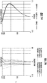
FIG. 10A shows a field curvature plot andFIG. 10B shows a distortion plot for the exemplary embodiment of the present application. As illustrated, distortion is kept below 1% using a higher order aspheric surface. For the exemplary embodiment (Design 16 in Table 2), the field curvature and distortion both are acceptable and distortion is kept less than 0.2%. There is spherical aberration and longitudinal chromatic aberration in the system. Spot diagram can be less than 60 microns on a high field. However, given the track length and limit to only two plastic lenses, this is the best performance attainable. More lenses would provide much better results. Therefore, the present application is a diffraction-limited system. A balanced design approach is taken keeping in mind customer needs, existing housing, and most importantly, cost. - In
FIG. 11 , a plot of Seidel sums indicates Seidel surface contributions of thelenses lens surface 50/52/56/58 where thestop 59 was placed. The last column shows the sum of all aberrations in the system. The bars are representation of various aberrations in the system. This plot shows thesurfaces surface 2. -
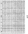
FIGS. 12 and13 illustrate a ghost analysis for the resultinglogo 72 of the exemplary embodiment. The ghost analysis was performed by setting up the imaging and the condenser lenses in a forward configuration. In non-sequential mode, a total of 20 million rays were traced using 10 Lumen lambertian source and random sampling. A 3-D layout of a non-sequential mode is shown inFIG. 13 . Using non-sequential ray tracing, stray lights reaching the detector were identified usinglog 5 scale and true color plot. Screen plane is identified as a detector object in non-sequential layout. Ghost analysis is done primarily to identify the surface(s) 50/52/56/58 that contribute to the stray light in order to apply antireflection (AR) coating on those surfaces to mitigate the stray light effect. - The ghosting in an optical system is also analyzed/simulated since internal reflection from multiple surfaces can degrade the overall image quality. Off-axis rays from LED through the logo are included in the ghost simulation. However, for the
exemplary logo projector 40, scattering may generally be not as important because the scatter model of the chosen plastic material may be unknown. - The exemplary embodiment of the present application mitigates axis bouncing of rays between the lens surfaces 50/52/56/58, which can cause light to bounce toward the
target surface 70. This mitigation is done by isolating and identifying surfaces that contribute the most stray light while illuminated and then applying anti-reflective (AR) coating on them. - In the exemplary embodiment, the tilted target surface plane requirement is thirty degrees.
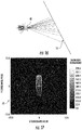
FIG. 16 is a plot using non sequential Zemax simulation showing the tilted plane of thetarget surface 70. To correct the distortion effect of a resultingimage 72 on the tiltedscreen plane 70, thelogo 46 within theprojector 40 was designed using a skewed image. Light propagating through the skewed image cancels the distortion effect of the tilted plane of thetarget surface 70 and thus corrects tilt-related skew effect and maintains image uniformity. The skew of thelogo 46 is obtained by reverse ray tracing from the tilted screen plane to the object plane.FIGS. 14A and14B provide an example generated with thelogo 46 as a skewed Lincoln® logo. - Uniformity of the resulting
image 72 is shown inFIG 17 . The uniformity curve is somewhat tilted to the right due to using skewedimage 46 for the 30 degree tilt of thetarget surface 70; apart from that, proper uniformity is maintained throughout theimage 72. -
FIG. 15 shows tolerancing results along with expected sensitivity to manufacturing tolerance. Tolerance analysis may also be performed in designing theprojector 40 of the present invention. During manufacturing, a small change in any of thelens FIG. 15 is a radius of curvature. - One skilled in the art would appreciate that the
logo projector 40 andtarget surface 70 of the present application may be used in various locations about avehicle cabin 1. As non-limiting examples shown inFIG. 1 , thetarget surface 70 could be defined by other vehicle cabin locations including: awindow 900, awindshield 902, arear view mirror 904, a housing/mount 906 for the rearview mirror, aglovebox 908, adashboard 910, aside 912 of thecenter console 10, aforward portion 914 of the center console, apillar 916, afloor 918, or the like. As further non-limiting examples, thelogo projector 40 could be mounted in or on vehicle cabin locations including: therearview mirror 904, a mount/housing 906 for the rearview mirror, theglovebox 908, thedashboard 910, a portion of thecenter console 910, aheadrest 920, anyother armrest 922, a door panel 924, an instrument panel 926, apillar 916, or the like. In exterior applications, the projector likewise can be provided in any suitable area of the car, with non-limiting examples (not illustrated) including a door, door handle, quarter panels, pillars, roof, and/or roof rack. - Having thus described the presently preferred embodiments in detail, it is to be appreciated and will be apparent to those skilled in the art that many physical changes, only a few of which are exemplified in the detailed description of the invention, could be made without altering the inventive concepts and principles embodied therein. It is also to be appreciated that numerous embodiments incorporating only part of the preferred embodiment are possible which do not alter, with respect to those parts, the inventive concepts and principles embodied therein. The present embodiments and optional configurations are therefore to be considered in all respects as exemplary and/or illustrative and not restrictive, the scope of the invention being indicated by the appended claims rather than by the foregoing description, and all alternate embodiments and changes to this embodiment which come within the meaning and range of equivalency of said claims are therefore to be embraced therein.
Claims (12)
- A logo projector, comprising:an LED light source;a condenser;a logo to be projected; andonly first and second imaging lenses,wherein the logo projector has a track length of less than 15 mm, and wherein the logo projector produces a resulting image on a target surface.
- The logo projector of claim 1, wherein the first and second imaging lenses are one of PMMA and PC material.
- The logo projector of claim 1, wherein the first and second imaging lenses both have a higher order aspheric surface.
- The logo projector of claim 1, wherein the logo projector provides a telecentricity of 0 degrees.
- A projection system, comprising:the logo projector of claim 1; andthe target surface, wherein the target surface is tilted at about 30 degrees relative to the logo projector and the target surface is located at a distance of about 75 mm from the logo projector.
- A vehicle logo display system, comprising:a logo projector, comprising:an LED light source,a condenser,a logo to be projected, andfirst and second imaging lenses, wherein the logo projector is mounted in a first vehicle location; anda target surface at a second vehicle location,wherein the logo projector has a track length of less than 15 mm, and wherein the logo projector produces a resulting image on the target surface.
- The vehicle logo display system of claim 7, wherein the first vehicle location is an armrest.
- The vehicle logo display system of claim 8, wherein the second vehicle location is a center console.
- The vehicle logo display system of claim 8, wherein the logo projector is embedded within the armrest.
- The vehicle logo display system of claim 7, wherein the target surface is tilted at 30 degrees relative to the logo projector.
- The vehicle logo display system of claim 7, wherein the target surface is at a distance of about 75 mm from the logo projector.
- A logo projector, consisting of:a light source;a condenser;a logo to be projected; andfirst and second imaging lenses formed of one of PMMA and PC material,wherein the logo projector has a track length of less than 15 mm.
Applications Claiming Priority (2)
| Application Number | Priority Date | Filing Date | Title |
|---|---|---|---|
| US201862742084P | 2018-10-05 | 2018-10-05 | |
| US16/369,181 US10684538B2 (en) | 2018-10-05 | 2019-03-29 | Miniature logo projector design for automotive interior lighting |
Publications (3)
| Publication Number | Publication Date |
|---|---|
| EP3657227A2 true EP3657227A2 (en) | 2020-05-27 |
| EP3657227A3 EP3657227A3 (en) | 2020-08-05 |
| EP3657227B1 EP3657227B1 (en) | 2023-05-31 |
Family
ID=70052141
Family Applications (1)
| Application Number | Title | Priority Date | Filing Date |
|---|---|---|---|
| EP19201500.6A Active EP3657227B1 (en) | 2018-10-05 | 2019-10-04 | Miniature logo projector design for automotive interior lighting |
Country Status (2)
| Country | Link |
|---|---|
| US (1) | US10684538B2 (en) |
| EP (1) | EP3657227B1 (en) |
Families Citing this family (3)
| Publication number | Priority date | Publication date | Assignee | Title |
|---|---|---|---|---|
| CN111596510B (en) * | 2020-06-17 | 2025-01-24 | 宁波福尔达智能科技股份有限公司 | Pattern generating device and its application |
| DE102020216046B3 (en) | 2020-12-16 | 2022-05-05 | OSRAM CONTINENTAL GmbH | OPTICAL GRAPHIC PROJECTION DEVICE AND VEHICLE WITH OPTICAL GRAPHIC PROJECTION DEVICE |
| GB2624634B (en) * | 2022-11-22 | 2025-05-07 | Bayerische Motoren Werke Ag | Integration of Projector |
Family Cites Families (6)
| Publication number | Priority date | Publication date | Assignee | Title |
|---|---|---|---|---|
| DE102004031700B4 (en) * | 2004-06-30 | 2010-02-18 | Airbus Deutschland Gmbh | Airplane with information display system |
| WO2011082998A1 (en) * | 2009-12-15 | 2011-07-14 | Airbus Operations Gmbh | Supply module for passenger transport vehicles |
| ES2561133B1 (en) * | 2014-07-24 | 2016-12-01 | Alejandro Rodriguez Barros | MULTIFUNCTION OUTDOOR REAR VIEW MIRROR WITH LASER ISSUED DEVICE |
| CN109073961A (en) * | 2016-04-01 | 2018-12-21 | B/E航空公司 | projection information display |
| US9869438B2 (en) | 2016-05-12 | 2018-01-16 | GM Global Technology Operations LLC | Dynamic logo projection system and method of using the same |
| US10836318B2 (en) * | 2017-10-16 | 2020-11-17 | SMR Patents S.à.r.l. | Logo lamp assembly and method of using same |
-
2019
- 2019-03-29 US US16/369,181 patent/US10684538B2/en not_active Expired - Fee Related
- 2019-10-04 EP EP19201500.6A patent/EP3657227B1/en active Active
Also Published As
| Publication number | Publication date |
|---|---|
| US20200110330A1 (en) | 2020-04-09 |
| US10684538B2 (en) | 2020-06-16 |
| EP3657227B1 (en) | 2023-05-31 |
| EP3657227A3 (en) | 2020-08-05 |
Similar Documents
| Publication | Publication Date | Title |
|---|---|---|
| EP2270587B1 (en) | Projection type image display device | |
| JP6582245B2 (en) | Head-up display and vehicle | |
| US9348210B2 (en) | Projection apparatus and transparent screen for it | |
| US11327304B2 (en) | Windshield head-up display, and method for suppressing ghost image | |
| EP3657227B1 (en) | Miniature logo projector design for automotive interior lighting | |
| US9291888B2 (en) | Linear fresnel lens sheet, transmissive display device and roll-shaped mold for producing linear fresnel lens sheet | |
| KR101572132B1 (en) | Optical System for Focus Adjustable Head Up Display | |
| KR20160090310A (en) | Imaging optical unit and display device having such an imaging optical unit | |
| US20180067317A1 (en) | Head mounted display with reduced thickness using a single axis optical system | |
| JP6630921B2 (en) | Head-up display and moving object equipped with head-up display | |
| US6598976B2 (en) | Method and apparatus for image enhancement and aberration corrections in a small real image projection system, using an off-axis reflector, neutral density window, and an aspheric corrected surface of revolution | |
| JP2010139639A (en) | Reflective screen | |
| US10371950B2 (en) | Imaging optical unit for generating a virtual image and smartglasses | |
| EP1783527B1 (en) | Projection type image display | |
| US9581888B2 (en) | Projection apparatus | |
| JP2013064816A (en) | Image display device | |
| US20070024821A1 (en) | Cabinet-surface-mounted projection lens and methods | |
| US11204498B2 (en) | Optical element with a fresnel structure, and display device with such an optical element | |
| KR20110101931A (en) | Head device using multiple lenses | |
| KR20200076160A (en) | Optical system using single lens |
Legal Events
| Date | Code | Title | Description |
|---|---|---|---|
| PUAI | Public reference made under article 153(3) epc to a published international application that has entered the european phase |
Free format text: ORIGINAL CODE: 0009012 |
|
| STAA | Information on the status of an ep patent application or granted ep patent |
Free format text: STATUS: REQUEST FOR EXAMINATION WAS MADE |
|
| 17P | Request for examination filed |
Effective date: 20191004 |
|
| AK | Designated contracting states |
Kind code of ref document: A2 Designated state(s): AL AT BE BG CH CY CZ DE DK EE ES FI FR GB GR HR HU IE IS IT LI LT LU LV MC MK MT NL NO PL PT RO RS SE SI SK SM TR |
|
| AX | Request for extension of the european patent |
Extension state: BA ME |
|
| PUAL | Search report despatched |
Free format text: ORIGINAL CODE: 0009013 |
|
| AK | Designated contracting states |
Kind code of ref document: A3 Designated state(s): AL AT BE BG CH CY CZ DE DK EE ES FI FR GB GR HR HU IE IS IT LI LT LU LV MC MK MT NL NO PL PT RO RS SE SI SK SM TR |
|
| AX | Request for extension of the european patent |
Extension state: BA ME |
|
| RIC1 | Information provided on ipc code assigned before grant |
Ipc: G02B 19/00 20060101AFI20200702BHEP |
|
| REG | Reference to a national code |
Ref country code: DE Ref legal event code: R079 Ref document number: 602019029489 Country of ref document: DE Free format text: PREVIOUS MAIN CLASS: G02B0019000000 Ipc: B60Q0003760000 |
|
| RIC1 | Information provided on ipc code assigned before grant |
Ipc: G09F 19/18 20060101ALI20221129BHEP Ipc: G02B 19/00 20060101ALI20221129BHEP Ipc: G09F 21/04 20060101ALI20221129BHEP Ipc: G09F 7/00 20060101ALI20221129BHEP Ipc: G03B 21/20 20060101ALI20221129BHEP Ipc: G03B 21/00 20060101ALI20221129BHEP Ipc: B60Q 3/76 20170101AFI20221129BHEP |
|
| INTG | Intention to grant announced |
Effective date: 20221215 |
|
| GRAS | Grant fee paid |
Free format text: ORIGINAL CODE: EPIDOSNIGR3 |
|
| STAA | Information on the status of an ep patent application or granted ep patent |
Free format text: STATUS: GRANT OF PATENT IS INTENDED |
|
| GRAA | (expected) grant |
Free format text: ORIGINAL CODE: 0009210 |
|
| STAA | Information on the status of an ep patent application or granted ep patent |
Free format text: STATUS: THE PATENT HAS BEEN GRANTED |
|
| AK | Designated contracting states |
Kind code of ref document: B1 Designated state(s): AL AT BE BG CH CY CZ DE DK EE ES FI FR GB GR HR HU IE IS IT LI LT LU LV MC MK MT NL NO PL PT RO RS SE SI SK SM TR |
|
| REG | Reference to a national code |
Ref country code: GB Ref legal event code: FG4D Ref country code: CH Ref legal event code: EP |
|
| REG | Reference to a national code |
Ref country code: AT Ref legal event code: REF Ref document number: 1570751 Country of ref document: AT Kind code of ref document: T Effective date: 20230615 Ref country code: DE Ref legal event code: R096 Ref document number: 602019029489 Country of ref document: DE |
|
| REG | Reference to a national code |
Ref country code: IE Ref legal event code: FG4D |
|
| REG | Reference to a national code |
Ref country code: CH Ref legal event code: PK Free format text: BERICHTIGUNGEN |
|
| REG | Reference to a national code |
Ref country code: LT Ref legal event code: MG9D |
|
| RAP2 | Party data changed (patent owner data changed or rights of a patent transferred) |
Owner name: FLEX, LTD. |
|
| RIN2 | Information on inventor provided after grant (corrected) |
Inventor name: SUNG, JINWON Inventor name: CHATTERJEE, RON |
|
| REG | Reference to a national code |
Ref country code: NL Ref legal event code: MP Effective date: 20230531 |
|
| REG | Reference to a national code |
Ref country code: AT Ref legal event code: MK05 Ref document number: 1570751 Country of ref document: AT Kind code of ref document: T Effective date: 20230531 |
|
| PG25 | Lapsed in a contracting state [announced via postgrant information from national office to epo] |
Ref country code: SE Free format text: LAPSE BECAUSE OF FAILURE TO SUBMIT A TRANSLATION OF THE DESCRIPTION OR TO PAY THE FEE WITHIN THE PRESCRIBED TIME-LIMIT Effective date: 20230531 Ref country code: NO Free format text: LAPSE BECAUSE OF FAILURE TO SUBMIT A TRANSLATION OF THE DESCRIPTION OR TO PAY THE FEE WITHIN THE PRESCRIBED TIME-LIMIT Effective date: 20230831 Ref country code: ES Free format text: LAPSE BECAUSE OF FAILURE TO SUBMIT A TRANSLATION OF THE DESCRIPTION OR TO PAY THE FEE WITHIN THE PRESCRIBED TIME-LIMIT Effective date: 20230531 Ref country code: AT Free format text: LAPSE BECAUSE OF FAILURE TO SUBMIT A TRANSLATION OF THE DESCRIPTION OR TO PAY THE FEE WITHIN THE PRESCRIBED TIME-LIMIT Effective date: 20230531 |
|
| REG | Reference to a national code |
Ref country code: DE Ref legal event code: R081 Ref document number: 602019029489 Country of ref document: DE Owner name: FLEX LTD., SG Free format text: FORMER OWNERS: CHATTERJEE, RON, FORT WAYNE, IN, US; SUNG, JINWON, TROY, MI, US |
|
| PG25 | Lapsed in a contracting state [announced via postgrant information from national office to epo] |
Ref country code: RS Free format text: LAPSE BECAUSE OF FAILURE TO SUBMIT A TRANSLATION OF THE DESCRIPTION OR TO PAY THE FEE WITHIN THE PRESCRIBED TIME-LIMIT Effective date: 20230531 Ref country code: PL Free format text: LAPSE BECAUSE OF FAILURE TO SUBMIT A TRANSLATION OF THE DESCRIPTION OR TO PAY THE FEE WITHIN THE PRESCRIBED TIME-LIMIT Effective date: 20230531 Ref country code: NL Free format text: LAPSE BECAUSE OF FAILURE TO SUBMIT A TRANSLATION OF THE DESCRIPTION OR TO PAY THE FEE WITHIN THE PRESCRIBED TIME-LIMIT Effective date: 20230531 Ref country code: LV Free format text: LAPSE BECAUSE OF FAILURE TO SUBMIT A TRANSLATION OF THE DESCRIPTION OR TO PAY THE FEE WITHIN THE PRESCRIBED TIME-LIMIT Effective date: 20230531 Ref country code: LT Free format text: LAPSE BECAUSE OF FAILURE TO SUBMIT A TRANSLATION OF THE DESCRIPTION OR TO PAY THE FEE WITHIN THE PRESCRIBED TIME-LIMIT Effective date: 20230531 Ref country code: IS Free format text: LAPSE BECAUSE OF FAILURE TO SUBMIT A TRANSLATION OF THE DESCRIPTION OR TO PAY THE FEE WITHIN THE PRESCRIBED TIME-LIMIT Effective date: 20230930 Ref country code: HR Free format text: LAPSE BECAUSE OF FAILURE TO SUBMIT A TRANSLATION OF THE DESCRIPTION OR TO PAY THE FEE WITHIN THE PRESCRIBED TIME-LIMIT Effective date: 20230531 Ref country code: GR Free format text: LAPSE BECAUSE OF FAILURE TO SUBMIT A TRANSLATION OF THE DESCRIPTION OR TO PAY THE FEE WITHIN THE PRESCRIBED TIME-LIMIT Effective date: 20230901 |
|
| PG25 | Lapsed in a contracting state [announced via postgrant information from national office to epo] |
Ref country code: FI Free format text: LAPSE BECAUSE OF FAILURE TO SUBMIT A TRANSLATION OF THE DESCRIPTION OR TO PAY THE FEE WITHIN THE PRESCRIBED TIME-LIMIT Effective date: 20230531 |
|
| PG25 | Lapsed in a contracting state [announced via postgrant information from national office to epo] |
Ref country code: SK Free format text: LAPSE BECAUSE OF FAILURE TO SUBMIT A TRANSLATION OF THE DESCRIPTION OR TO PAY THE FEE WITHIN THE PRESCRIBED TIME-LIMIT Effective date: 20230531 |
|
| PG25 | Lapsed in a contracting state [announced via postgrant information from national office to epo] |
Ref country code: SM Free format text: LAPSE BECAUSE OF FAILURE TO SUBMIT A TRANSLATION OF THE DESCRIPTION OR TO PAY THE FEE WITHIN THE PRESCRIBED TIME-LIMIT Effective date: 20230531 Ref country code: SK Free format text: LAPSE BECAUSE OF FAILURE TO SUBMIT A TRANSLATION OF THE DESCRIPTION OR TO PAY THE FEE WITHIN THE PRESCRIBED TIME-LIMIT Effective date: 20230531 Ref country code: RO Free format text: LAPSE BECAUSE OF FAILURE TO SUBMIT A TRANSLATION OF THE DESCRIPTION OR TO PAY THE FEE WITHIN THE PRESCRIBED TIME-LIMIT Effective date: 20230531 Ref country code: PT Free format text: LAPSE BECAUSE OF FAILURE TO SUBMIT A TRANSLATION OF THE DESCRIPTION OR TO PAY THE FEE WITHIN THE PRESCRIBED TIME-LIMIT Effective date: 20231002 Ref country code: EE Free format text: LAPSE BECAUSE OF FAILURE TO SUBMIT A TRANSLATION OF THE DESCRIPTION OR TO PAY THE FEE WITHIN THE PRESCRIBED TIME-LIMIT Effective date: 20230531 Ref country code: DK Free format text: LAPSE BECAUSE OF FAILURE TO SUBMIT A TRANSLATION OF THE DESCRIPTION OR TO PAY THE FEE WITHIN THE PRESCRIBED TIME-LIMIT Effective date: 20230531 Ref country code: CZ Free format text: LAPSE BECAUSE OF FAILURE TO SUBMIT A TRANSLATION OF THE DESCRIPTION OR TO PAY THE FEE WITHIN THE PRESCRIBED TIME-LIMIT Effective date: 20230531 |
|
| REG | Reference to a national code |
Ref country code: DE Ref legal event code: R097 Ref document number: 602019029489 Country of ref document: DE |
|
| PLBE | No opposition filed within time limit |
Free format text: ORIGINAL CODE: 0009261 |
|
| STAA | Information on the status of an ep patent application or granted ep patent |
Free format text: STATUS: NO OPPOSITION FILED WITHIN TIME LIMIT |
|
| PG25 | Lapsed in a contracting state [announced via postgrant information from national office to epo] |
Ref country code: SI Free format text: LAPSE BECAUSE OF FAILURE TO SUBMIT A TRANSLATION OF THE DESCRIPTION OR TO PAY THE FEE WITHIN THE PRESCRIBED TIME-LIMIT Effective date: 20230531 |
|
| 26N | No opposition filed |
Effective date: 20240301 |
|
| PG25 | Lapsed in a contracting state [announced via postgrant information from national office to epo] |
Ref country code: SI Free format text: LAPSE BECAUSE OF FAILURE TO SUBMIT A TRANSLATION OF THE DESCRIPTION OR TO PAY THE FEE WITHIN THE PRESCRIBED TIME-LIMIT Effective date: 20230531 Ref country code: IT Free format text: LAPSE BECAUSE OF FAILURE TO SUBMIT A TRANSLATION OF THE DESCRIPTION OR TO PAY THE FEE WITHIN THE PRESCRIBED TIME-LIMIT Effective date: 20230531 Ref country code: MC Free format text: LAPSE BECAUSE OF FAILURE TO SUBMIT A TRANSLATION OF THE DESCRIPTION OR TO PAY THE FEE WITHIN THE PRESCRIBED TIME-LIMIT Effective date: 20230531 |
|
| REG | Reference to a national code |
Ref country code: CH Ref legal event code: PL |
|
| REG | Reference to a national code |
Ref country code: BE Ref legal event code: MM Effective date: 20231031 |
|
| PG25 | Lapsed in a contracting state [announced via postgrant information from national office to epo] |
Ref country code: LU Free format text: LAPSE BECAUSE OF NON-PAYMENT OF DUE FEES Effective date: 20231004 |
|
| GBPC | Gb: european patent ceased through non-payment of renewal fee |
Effective date: 20231004 |
|
| PG25 | Lapsed in a contracting state [announced via postgrant information from national office to epo] |
Ref country code: LU Free format text: LAPSE BECAUSE OF NON-PAYMENT OF DUE FEES Effective date: 20231004 |
|
| PG25 | Lapsed in a contracting state [announced via postgrant information from national office to epo] |
Ref country code: GB Free format text: LAPSE BECAUSE OF NON-PAYMENT OF DUE FEES Effective date: 20231004 |
|
| PG25 | Lapsed in a contracting state [announced via postgrant information from national office to epo] |
Ref country code: CH Free format text: LAPSE BECAUSE OF NON-PAYMENT OF DUE FEES Effective date: 20231031 |
|
| PG25 | Lapsed in a contracting state [announced via postgrant information from national office to epo] |
Ref country code: GB Free format text: LAPSE BECAUSE OF NON-PAYMENT OF DUE FEES Effective date: 20231004 Ref country code: FR Free format text: LAPSE BECAUSE OF NON-PAYMENT OF DUE FEES Effective date: 20231031 Ref country code: CH Free format text: LAPSE BECAUSE OF NON-PAYMENT OF DUE FEES Effective date: 20231031 |
|
| PG25 | Lapsed in a contracting state [announced via postgrant information from national office to epo] |
Ref country code: BE Free format text: LAPSE BECAUSE OF NON-PAYMENT OF DUE FEES Effective date: 20231031 |
|
| PG25 | Lapsed in a contracting state [announced via postgrant information from national office to epo] |
Ref country code: IE Free format text: LAPSE BECAUSE OF NON-PAYMENT OF DUE FEES Effective date: 20231004 |
|
| PG25 | Lapsed in a contracting state [announced via postgrant information from national office to epo] |
Ref country code: IE Free format text: LAPSE BECAUSE OF NON-PAYMENT OF DUE FEES Effective date: 20231004 |
|
| PG25 | Lapsed in a contracting state [announced via postgrant information from national office to epo] |
Ref country code: BG Free format text: LAPSE BECAUSE OF FAILURE TO SUBMIT A TRANSLATION OF THE DESCRIPTION OR TO PAY THE FEE WITHIN THE PRESCRIBED TIME-LIMIT Effective date: 20230531 |
|
| PG25 | Lapsed in a contracting state [announced via postgrant information from national office to epo] |
Ref country code: BG Free format text: LAPSE BECAUSE OF FAILURE TO SUBMIT A TRANSLATION OF THE DESCRIPTION OR TO PAY THE FEE WITHIN THE PRESCRIBED TIME-LIMIT Effective date: 20230531 |
|
| PGFP | Annual fee paid to national office [announced via postgrant information from national office to epo] |
Ref country code: DE Payment date: 20241029 Year of fee payment: 6 |
|
| PG25 | Lapsed in a contracting state [announced via postgrant information from national office to epo] |
Ref country code: CY Free format text: LAPSE BECAUSE OF FAILURE TO SUBMIT A TRANSLATION OF THE DESCRIPTION OR TO PAY THE FEE WITHIN THE PRESCRIBED TIME-LIMIT; INVALID AB INITIO Effective date: 20191004 |
|
| PG25 | Lapsed in a contracting state [announced via postgrant information from national office to epo] |
Ref country code: HU Free format text: LAPSE BECAUSE OF FAILURE TO SUBMIT A TRANSLATION OF THE DESCRIPTION OR TO PAY THE FEE WITHIN THE PRESCRIBED TIME-LIMIT; INVALID AB INITIO Effective date: 20191004 |
|
| PG25 | Lapsed in a contracting state [announced via postgrant information from national office to epo] |
Ref country code: TR Free format text: LAPSE BECAUSE OF FAILURE TO SUBMIT A TRANSLATION OF THE DESCRIPTION OR TO PAY THE FEE WITHIN THE PRESCRIBED TIME-LIMIT Effective date: 20230531 |