EP3657184A1 - Isolation resistance measurement of power system in vehicle - Google Patents
Isolation resistance measurement of power system in vehicle Download PDFInfo
- Publication number
- EP3657184A1 EP3657184A1 EP19210065.9A EP19210065A EP3657184A1 EP 3657184 A1 EP3657184 A1 EP 3657184A1 EP 19210065 A EP19210065 A EP 19210065A EP 3657184 A1 EP3657184 A1 EP 3657184A1
- Authority
- EP
- European Patent Office
- Prior art keywords
- isolation resistance
- resistance
- voltage
- node
- power system
- Prior art date
- Legal status (The legal status is an assumption and is not a legal conclusion. Google has not performed a legal analysis and makes no representation as to the accuracy of the status listed.)
- Granted
Links
Images



Classifications
-
- B—PERFORMING OPERATIONS; TRANSPORTING
- B60—VEHICLES IN GENERAL
- B60L—PROPULSION OF ELECTRICALLY-PROPELLED VEHICLES; SUPPLYING ELECTRIC POWER FOR AUXILIARY EQUIPMENT OF ELECTRICALLY-PROPELLED VEHICLES; ELECTRODYNAMIC BRAKE SYSTEMS FOR VEHICLES IN GENERAL; MAGNETIC SUSPENSION OR LEVITATION FOR VEHICLES; MONITORING OPERATING VARIABLES OF ELECTRICALLY-PROPELLED VEHICLES; ELECTRIC SAFETY DEVICES FOR ELECTRICALLY-PROPELLED VEHICLES
- B60L3/00—Electric devices on electrically-propelled vehicles for safety purposes; Monitoring operating variables, e.g. speed, deceleration or energy consumption
- B60L3/0023—Detecting, eliminating, remedying or compensating for drive train abnormalities, e.g. failures within the drive train
- B60L3/0069—Detecting, eliminating, remedying or compensating for drive train abnormalities, e.g. failures within the drive train relating to the isolation, e.g. ground fault or leak current
-
- G—PHYSICS
- G01—MEASURING; TESTING
- G01R—MEASURING ELECTRIC VARIABLES; MEASURING MAGNETIC VARIABLES
- G01R27/00—Arrangements for measuring resistance, reactance, impedance, or electric characteristics derived therefrom
- G01R27/02—Measuring real or complex resistance, reactance, impedance, or other two-pole characteristics derived therefrom, e.g. time constant
- G01R27/025—Measuring very high resistances, e.g. isolation resistances, i.e. megohm-meters
-
- G—PHYSICS
- G01—MEASURING; TESTING
- G01R—MEASURING ELECTRIC VARIABLES; MEASURING MAGNETIC VARIABLES
- G01R31/00—Arrangements for testing electric properties; Arrangements for locating electric faults; Arrangements for electrical testing characterised by what is being tested not provided for elsewhere
- G01R31/005—Testing of electric installations on transport means
- G01R31/006—Testing of electric installations on transport means on road vehicles, e.g. automobiles or trucks
-
- G—PHYSICS
- G01—MEASURING; TESTING
- G01R—MEASURING ELECTRIC VARIABLES; MEASURING MAGNETIC VARIABLES
- G01R31/00—Arrangements for testing electric properties; Arrangements for locating electric faults; Arrangements for electrical testing characterised by what is being tested not provided for elsewhere
- G01R31/50—Testing of electric apparatus, lines, cables or components for short-circuits, continuity, leakage current or incorrect line connections
-
- G—PHYSICS
- G01—MEASURING; TESTING
- G01R—MEASURING ELECTRIC VARIABLES; MEASURING MAGNETIC VARIABLES
- G01R31/00—Arrangements for testing electric properties; Arrangements for locating electric faults; Arrangements for electrical testing characterised by what is being tested not provided for elsewhere
- G01R31/50—Testing of electric apparatus, lines, cables or components for short-circuits, continuity, leakage current or incorrect line connections
- G01R31/52—Testing for short-circuits, leakage current or ground faults
-
- G—PHYSICS
- G01—MEASURING; TESTING
- G01R—MEASURING ELECTRIC VARIABLES; MEASURING MAGNETIC VARIABLES
- G01R31/00—Arrangements for testing electric properties; Arrangements for locating electric faults; Arrangements for electrical testing characterised by what is being tested not provided for elsewhere
- G01R31/005—Testing of electric installations on transport means
- G01R31/006—Testing of electric installations on transport means on road vehicles, e.g. automobiles or trucks
- G01R31/007—Testing of electric installations on transport means on road vehicles, e.g. automobiles or trucks using microprocessors or computers
-
- Y—GENERAL TAGGING OF NEW TECHNOLOGICAL DEVELOPMENTS; GENERAL TAGGING OF CROSS-SECTIONAL TECHNOLOGIES SPANNING OVER SEVERAL SECTIONS OF THE IPC; TECHNICAL SUBJECTS COVERED BY FORMER USPC CROSS-REFERENCE ART COLLECTIONS [XRACs] AND DIGESTS
- Y02—TECHNOLOGIES OR APPLICATIONS FOR MITIGATION OR ADAPTATION AGAINST CLIMATE CHANGE
- Y02T—CLIMATE CHANGE MITIGATION TECHNOLOGIES RELATED TO TRANSPORTATION
- Y02T10/00—Road transport of goods or passengers
- Y02T10/60—Other road transportation technologies with climate change mitigation effect
- Y02T10/70—Energy storage systems for electromobility, e.g. batteries
Definitions
- the disclosure relates to resistance measurements in a vehicle.
- a vehicle is partially, primarily, or exclusively powered by a power system, such as one or more batteries, fuel cells, and/or capacitor banks. Due to the power needs of some vehicles, the power system tends to be a high voltage or high-power power system.
- the vehicle chassis e.g., vehicle frame
- the chassis of the vehicle and the power system of the vehicle should be electrically isolated.
- the disclosure describes techniques for measuring the isolation resistance between a power system and a chassis of a vehicle.
- the power system may be designed with a first isolation resistance that electrically isolates a first node (e.g., having positive or negative polarity) of the power system from the chassis (e.g., limits the flow of current between the first node of the power system and the chassis), and with a second isolation resistance that electrically isolates a second node (e.g., having the other of the positive or negative polarity) of the power system from the chassis.
- a first isolation resistance that electrically isolates a first node (e.g., having positive or negative polarity) of the power system from the chassis
- a second isolation resistance that electrically isolates a second node (e.g., having the other of the positive or negative polarity) of the power system from the chassis.
- the resistance of this current path can change and possibly reduce one or both of the first isolation resistance and the second isolation resistance (e.g., by creating a current path).
- This disclosure describes example techniques to determine whether there is sufficient isolation between the power system and the chassis in the electrical vehicle by, for example, determining the value of both the first isolation resistance and the second isolation resistance.
- the disclosure describes a method comprising determining a first isolation resistance between a first node of a power system in an electrical vehicle (EV) and a chassis of the EV, determining a second isolation resistance between a second node of the power system in the EV and the chassis of the EV, determining that the first isolation resistance or the second isolation resistance is less than a threshold resistance, and outputting information based on the determination that the first isolation resistance or the second isolation resistance is less than the threshold resistance.
- EV electrical vehicle
- the disclosure describes a system comprising processing circuitry configured to determine a first isolation resistance between a first node of a power system and a chassis of an electric vehicle (EV), determine a second isolation resistance between a second node of the power system and the chassis of the EV, determine that the first isolation resistance or the second isolation resistance is less than a threshold resistance, and output information based on the determination that the first isolation resistance or the second isolation resistance is less than the threshold resistance.
- processing circuitry configured to determine a first isolation resistance between a first node of a power system and a chassis of an electric vehicle (EV), determine a second isolation resistance between a second node of the power system and the chassis of the EV, determine that the first isolation resistance or the second isolation resistance is less than a threshold resistance, and output information based on the determination that the first isolation resistance or the second isolation resistance is less than the threshold resistance.
- the disclosure describes a non-transitory computer-readable storage medium storing instructions thereon that when executed cause one or more processors to determine a first isolation resistance between a first node of a power system in an electrical vehicle (EV) and a chassis of the EV, determine a second isolation resistance between a second node of the power system in the EV and the chassis of the EV, determine that the first isolation resistance or the second isolation resistance is less than a threshold resistance, and output information based on the determination that the first isolation resistance or the second isolation resistance is less than the threshold resistance.
- EV electrical vehicle
- the disclosure describes a non-transitory computer-readable storage medium storing instructions thereon that when executed cause one or more processors to determine a first isolation resistance between a first node of a power system in an electrical vehicle (EV) and a chassis of the EV, determine a second isolation resistance between a second node of the power system in the EV and the chassis of the EV, determine that the first isolation resistance or the second isolation resistance is less than a threshold resistance,
- HV DC high voltage DC
- the HV DC system is designed to have property that the HV DC system is electrically isolated from the chassis.
- this can be considered as there being certain resistance between the HV DC system and the chassis. This resistance may not necessarily be due to a physical resistor between the HV DC system and the chassis, but, rather, a physical property of the HV DC system that there be certain isolation resistance between the HV DC system and the chassis.
- electrical current paths should be of relatively high resistance.
- the HV DC system includes a power system that includes a positive node and a negative node.
- a power system that includes a positive node and a negative node.
- a power management system may periodically (e.g., every 10 seconds) measure the isolation resistance between the power system and the chassis to ensure that the isolation resistance is greater than a threshold resistance.
- some techniques determine the parallel resistance between the positive node of the power system to the chassis and the negative node of the power system to the chassis. That is, the parallel resistance is the parallel combination of the resistance from each of the positive node and negative node of the power system to the chassis. In such techniques, there is a single resistance value that indicates the isolation resistance. Such techniques may be deficient because if there becomes a lower resistance current path, it is unknown whether the current path is from the positive node of the power system to the chassis or the negative node of the power system to the chassis.
- This disclosure describes example techniques to determine the isolation resistance for the positive node, and separately determine the isolation resistance for the negative node. If at least one of the isolation resistances is less than a threshold resistance, the power management system may output information indicating that the isolation resistance for at least one of the positive node or the negative node does not satisfy the threshold (e.g., is below the threshold), and in some examples, specify whether the isolation resistance for the positive node or the isolation resistance for the negative node is below the threshold allowing for ease of diagnosis.
- FIG. 1 is a block diagram illustrating an example power management system configured to perform one or more example techniques described in this disclosure.
- FIG. 1 illustrates a vehicle that includes power management system 10 (also called HV DC system 10) that includes power system 12 having a positive node 14A and a negative node 14B, electrical control unit (ECU) 16 (also called monitoring system 16) that includes processing circuitry 22, resistor R0 and switches SW1 and SW2, chassis 18, and load 20.
- Chassis 18 may be the metal housing of the electrical vehicle (EV) that includes power management system 10.
- chassis 18 is shown as being the ground potential.
- the illustrated ground potentials may be electrically coupled together.
- Processing circuitry 22 may represent one or more processors implemented as fixed-function processing circuits, programmable processing circuits, or a combination thereof.
- Fixed-function circuits refer to circuits that provide particular functionality and are pre-set on the operations that can be performed.
- Programmable circuits refer to circuits that can programmed to perform various tasks and provide flexible functionality in the operations that can be performed.
- programmable circuits may execute software or firmware that cause the programmable circuits to operate in the manner defined by instructions of the software or firmware.
- Fixed-function circuits may execute software instructions (e.g., to receive parameters or output parameters), but the types of operations that the fixed-function processing circuits perform are generally immutable.
- the one or more processing circuits may be distinct circuit blocks (fixed-function or programmable), and in some examples, the one or more circuits may be integrated circuits.
- Power system 12 may be one or more high voltage DC batteries, fuel cells, and/or capacitor banks having a regulator or some other circuitry that can generate a range of DC voltage levels that power load 20 to drive the vehicle.
- power system 12 includes positive node 14A and negative node 14B.
- Positive node 14A and negative node 14B may be the outputs of the regulator circuit or some other circuit and the voltage level between positive node 14A and negative node 14B can be approximately 400 V and can change based on whether EV is speeding or slowing down, as two example factors.
- FIG. 1 also illustrates resistances Ri1 and Ri2.
- Resistances Ri1 and Ri2 are conceptually shown as resistors that provide electrical isolation between positive node 14A to chassis 18 and negative node 14B to chassis 18.
- Ri1 and Ri2 are not necessarily physical resistors (although possible) and are property of power management system 10.
- resistances Ri1 and Ri2 illustrate resistance of a "possible current path" between positive node 14A and negative node 14B, respectively, to chassis 18. This possible current path may not be an actual current path through which current flows due to its high resistance, and should be considered as a conceptual current path.
- the first isolation resistance is between positive node 14A and chassis 18, and the second isolation resistance is between negative node 14B and chassis 18.
- Ri1 and Ri2 may be approximately 5 mega-ohms. However, there may be possibility that due to debris, water, component failure, etc. that Ri1 and Ri2 are reduced. Accordingly, ECU 16 (e.g., via processing circuitry 22) may be configured to periodically (e.g., every 10 seconds) determine a first isolation resistance between positive node 14A to chassis 18 and determine a second isolation resistance between negative node 14B to chassis 18.
- ECU 16 may determine whether the first isolation resistance or the second isolation resistance is less than a threshold resistance (e.g., less than 2.5 mega-ohms), and, if ECU 16 determines that the first isolation resistance or the second isolation resistance is less than the threshold resistance, output information indicating that at least one of the first isolation resistance or the second isolation resistance is less than the threshold resistance.
- a threshold resistance e.g., less than 2.5 mega-ohms
- ECU 16 may determine whether the first isolation resistance or the second isolation resistance is less than a threshold resistance.
- ECU 16 may compare a value representative of the first isolation resistance to a value representative of the threshold resistance and compare a value representative of the second isolation resistance to a value representative of the threshold resistance.
- a value representative of the first isolation resistance, the second isolation resistance, and the threshold resistance may be the actual values of the first isolation resistance, the second isolation resistance, and the threshold resistance, or an offset, inverted, or scaled version of the first isolation resistance, the second isolation resistance, and the threshold resistance.
- the value representative of the first isolation resistance and the threshold resistance is the actual value of the first isolation resistance and the threshold resistance.
- ECU 16 may determine that the first isolation resistance is less than a threshold resistance.
- the value representative of the first isolation resistance is the inverse of the actual value of the first isolation resistance (e.g., 1/(actual value of the first isolation resistance)), and that the value representative of the threshold resistance is also an inverted value.
- ECU 16 may determine that the first isolation resistance is less than a threshold resistance.
- ECU 16 may be configured to determine which one or both of the first isolation resistance and the second isolation resistance is less than the threshold resistance.
- Some other techniques determine an overall resistance value based on the first isolation resistance and the second isolation resistance (e.g., parallel resistance value of the first isolation resistance and the second isolation resistance). However, in such techniques, it may be unknown whether the first isolation resistance or the second isolation resistance reduced. For instance, ECU 16 may not be able to determine whether the isolation resistance between positive node 14A to chassis 18 was reduced, or whether the isolation resistance between negative node 14B to chassis 18 was reduced.
- ECU 16 may be configured to separately determine the first isolation resistance and the second isolation resistance. In this manner, any reduction in isolation resistance may be more easily diagnosed, as compared to using a parallel resistance value.
- ECU 16 (or monitoring system 16) is illustrated as including a first resistor R0 coupled to switch SW1 that couples to positive node 14A and a second resistor R0 coupled to switch SW2 that couples to negative node 14B.
- processing circuitry 22 of ECU 16 closes switch SW1 and leaves switch SW2 open so that first resistor R0 is parallel with Ri1.
- processing circuitry 22 of ECU 16 closes switch SW2 and leaves switch SW1 open so that second resistor R0 is parallel with Ri2. Examples of the first and second time instances are shown in FIGS. 2A and 2B .
- processing circuitry 22 of ECU 16 may measure the voltage across first resistor R0 (in the first time instance) and across second resistor R0 (in the second time instance). Based on the voltage measurements, voltage of power system 12, and value of resistor R0, ECU 16 may separately determine the first isolation resistance and the second isolation resistance.
- resistors R0 Although two resistors R0 are illustrated, it may be possible to use a single resistor R0 and a different combination of switches to achieve the same electrical configuration as described in this disclosure. Also, resistors R0 may not be connected to power management system 10 except for when measuring the isolation resistances.
- processing circuitry 22 may compare the first isolation resistance to a threshold resistance to determine whether the first isolation resistance is greater than or equal to the threshold resistance or less than the threshold resistance. Processing circuitry 22 may similarly compare the second isolation resistance to the threshold resistance to determine whether the second isolation resistance is greater than or equal to the threshold resistance or less than the threshold resistance. In some examples, the threshold resistance to which the second isolation resistance is compared may be different than the threshold resistance to which the first isolation resistance is compared, and in some examples, the threshold resistance to which the second isolation resistance is compared may be the same as the threshold resistance to which the first isolation resistance is compared. Based on the comparison, processing circuitry 22 may output information indicative of whether the first isolation resistance or the second isolation resistance, and in some examples, which one of the first isolation resistance or the second isolation resistance, is less than the threshold resistance.
- processing circuity 22 may output the information indicative of whether the first isolation resistance or the second isolation resistance, and in some examples, which one of the first isolation resistance or the second isolation resistance, is less than the threshold resistance to an on-board computing system of the vehicle.
- the on-board computing system may locally store the information or output the information to an on-board display system of the vehicle.
- processing circuitry 22 may be configured to output the stored information at a later time, such as upon request from a mechanic or sent by wireless communication as described below.
- processing circuity 22 may output information that one or both, and possibly which one, of the first and second resistances, are less than the threshold resistance. As one example, processing circuitry 22 may output an alert (e.g., on the on-board display system) or may output an alert to external computing system 26 via network 24.
- an alert e.g., on the on-board display system
- the vehicle may be communicatively coupled to external computing system 26 via network 24. Also, components of external computing system 26 may communicate with one another via network 24.
- Network 24 may represent any type of network by which communication between the vehicle and external computing system 26 may be accomplished.
- Network 24 may represent a public network (e.g., the Internet), a private network, a cellular network (including various cellular data networks, such as a 3G, 4G and/or 5G network), a personal area network, or combinations thereof.
- External computing system 26 may represent one or more devices configured to communicate via network 24 with the vehicle.
- Examples of external computing system 26 include, but are not limited to, servers, distributed computing systems (e.g., cloud-based computing systems), desktop computers, laptop computers, smart phones, tablets, etc.
- External computing system 26 may communicate via network 24 with the vehicle to monitor or otherwise retrieve data from one or more components of the vehicle, such as a navigation system, an infotainment system, an anti-lock braking system (ABS), a traction control (TC) system, an electronic stability control (ESC) system, a friction probing system, or any other component or system integrated into the vehicle or in communication with the vehicle.
- External computing system 26 may, in addition or as an alternative to monitoring the vehicle, communicate with the vehicle to update one or more of the above noted components of the vehicle.
- external computing system 26 may be a plurality of devices such as a server device and a smart phone.
- Processing circuitry 22 may output information indicative of whether, and which one of, the first or second isolation resistances are less than the threshold resistance to the server via network 24.
- the server may then output to the smart phone of a user (e.g., owner) of the vehicle information that indicates that the user should take the vehicle in to a service center for repair.
- a mechanic may be able to access the memory of the vehicle and retrieve information indicative of which one of the first and second resistances is less than the threshold resistance, as outputted and stored by processing circuitry 22.
- a system configured to perform the example techniques may include processing circuitry 22.
- processing circuitry 22 may be configured to determine a first isolation resistance between a first node of power system 12 and a chassis 18 of an electric vehicle (EV), determine a second isolation resistance between a second node of the power system 12 and the chassis 18 of the EV, determine that the first isolation resistance or the second isolation resistance is less than a threshold resistance, and output information based on the determination that the first isolation resistance or the second isolation resistance is less than the threshold resistance.
- EV electric vehicle
- the system may further include pole resistor R0 and switches SW1 and SW2. In some examples, the system may further include pole resistor R0, switches SW1 and SW2, and power system 12. In some examples, the system may further include pole resistor R0, switches SW1 and SW2, power system 12, and the EV. That is, the example techniques described in this disclosure are described with respect to a plurality of example systems.
- a first example of the plurality of example systems includes processing circuity 22, a second example of the plurality of example systems includes processing circuitry 22, pole resistor R0, and switches SW1 and SW2, a third example of the plurality of example systems includes processing circuitry 22, pole resistor R0, switches SW1 and SW2, and power system 12, and a fourth example of the plurality of example systems includes processing circuitry 22, pole resistor R0, switches SW1 and SW2, power system 12, and chassis 18.
- the first, second, third, and fourth example systems are described simply to ease with understanding and should not be considered limiting. Other combination of components, including additional or fewer components, may be possible and are contemplated as examples of the plurality of example systems.
- FIG. 2A is a block diagram illustrating a first configuration at a first time instance of an isolation resistance measurement circuit (e.g., combination of monitoring system and parts of HV DC system as illustrated in FIG. 1 ).
- FIG. 2B is a block diagram illustrating a second configuration at a second time instance of an isolation resistance measurement circuit.
- isolation resistance measurement circuit is used to describe components that are used to determine the isolation resistance.
- the isolation resistance circuit includes power system 12, processing circuitry 22, SW1, SW2, and R0.
- pole resistor R0 and measurements of voltage V1 and V2 are used to determine the isolation resistances.
- Ri1 and Ri2 represent the isolation resistances as shown in FIG. 1 .
- Vb is the voltage of power system 12 (e.g., the potential between positive node 14A to negative node 14B).
- the + sign in Vb corresponds to positive node 14A, and the - sign in Vb corresponds to negative node 14B.
- the ground symbol in FIGS. 2A and 2B is chassis 18.
- R0 similar to R0 of FIG. 1 , is a pole resistor used to determine first and second isolation resistances. As one example, R0 may be approximately 500 kilo-ohms.
- processing circuitry 22 of ECU 16 may configure the isolation resistance measurement circuit in a first configuration at a first time instance (e.g., by closing switch SW1 and leaving open switch SW2), as shown in FIG. 2A .
- ECU 16 may wait for the circuit to settle (e.g., so that there are no time-varying signal portions). As one example, processing circuitry 22 of ECU 16 may wait a few seconds (e.g., 4-5 seconds) or in the order of milliseconds.
- processing circuitry 22 of ECU 16 may measure a first voltage (e.g., V1). As illustrated, in the first configuration, resistor R0 is parallel with the first isolation resistance (e.g., Ri1).
- Processing circuitry 22 of ECU 16 may then configure the isolation resistance measurement circuit in a second configuration at a second time instance after the first time instance (e.g., by closing switch SW2 and leaving open switch SW1), as shown in FIG. 2B . Processing circuitry 22 of ECU 16 may again wait for the circuit to settle.
- ECU 16 may measure a second voltage (e.g., V2).
- resistor R0 is parallel with the second isolation resistance (e.g., Ri2).
- processing circuity 22 of ECU 16 may determine the first isolation resistance and the second isolation resistance.
- the first isolation resistance equals -(R0 ⁇ V1 + R0 ⁇ V2 - R0 ⁇ Vb)/V2.
- the second isolation resistance equals -(R0 ⁇ V1 + R0 ⁇ V2 - R0 ⁇ Vb)/V1. If there were no additional current paths between positive node 14A and chassis 18, then the first isolation resistance would equal the isolation resistance for which the system was designed. If there were no additional current paths between negative node 14B and chassis 18, then the second isolation resistance would be equal to the isolation resistance for which the system was designed.
- processing circuitry 22 of ECU 16 may determine that there is a current path between positive node 14A and chassis 18. If the second isolation resistance is less than the designed resistance, processing circuity 22 of ECU 16 may determine that there is a current path between negative node 14B and chassis 18. Processing circuitry 22 of ECU 16 may determine whether the first isolation resistance and/or the second isolation resistance is less than a threshold resistance. Based on the determination, processing circuitry 22 of ECU 16 may output information indicating whether the first isolation resistance and/or second isolation resistance is less than the threshold resistance.
- Some other techniques may be considered as a circuit topology that is essentially a biased voltage divider with a known total resistance between chassis 18 and the connected pole (e.g., pole resistor R0). In such cases, V1 and V2 may be determined, but these other techniques may not separately determine the isolation resistances. As described, there may be various sources of error including R0, Vb, and offset due to biasing source offset when total resistance is changed.
- Vb it is possible for Vb to change (e.g., when slowing or speeding), and change in a relatively short amount of time. As also mentioned above, it may be possible for a few seconds or many milliseconds to pass between ECU 16 determining the first voltage V1 at the first time instance when the isolation resistance measurement circuit is in the first configuration and ECU 16 determining the second voltage V2 at the second time instance when the isolation resistance measurement circuit is in the second configuration. Because there is a delay in the measurements of V1 and V2, it is possible that Vb changed between when V1 was measured and when V2 was measured.
- processing circuitry 22 of ECU 16 may be configured to scale at least one of V1 or Vb. Changes in Vb can be compensated, as long as the Vx/Vb ratio is maintained, where Vx is V1 or V2. For example, processing circuit 22 of ECU 16 may determine a ratio between V1 and Vb after determining V1 in the first configuration. Then, processing circuity 22 of ECU 16 may determine V2 in the second configuration, and Vb may have changed. In this example, in the equation to determine the second isolation resistance, ECU 16 may scale the value of V1 based on the ratio of V1/Vb in the first configuration or scale the value of Vb based on the ratio of V1/Vb in the first configuration.
- ECU 16 may first configure the isolation resistance measurement circuit in the configuration illustrated in FIG. 2B and measure V2, and then configure the isolation resistance measurement circuit in the configuration illustrated in FIG. 2A and measure V1. In such examples, to ensure proper scaling, ECU 16 may determine the ratio of V2/Vb and update the value for V2 or Vb as described above.
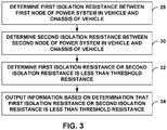
- FIG. 3 is a flowchart illustrating example techniques of operation in accordance with one or more examples described in this disclosure.
- Processing circuitry 22 of ECU 16 may determine a first isolation resistance between a first node of power system 12 in an EV and chassis 18 of the EV (28) and determine a second isolation resistance between a second node of power system 12 in the EV and chassis 18 of the EV (30).
- One example of the first node is node 14A or node 14B
- one example of the second node is the other one of node 14A or node 14B.
- processing circuitry 22 may determine the voltage V1 or V2 by closing one of SW1 or SW2 as illustrated in FIGS. 2A and 2B and determine the other one of voltage V1 or V2 by closing the other one of SW1 or SW2. Based on V1 and V2 and the voltage of power system 12 (e.g., Vb in FIGS. 2A and 2B ), processing circuitry 22 may determine first isolation resistance and the second isolation resistance as described above.
- Processing circuitry 22 may be configured to determine that the first isolation resistance or the second isolation resistance is less than a threshold resistance (32). For example, processing circuitry 22 may compare the first isolation resistance to the threshold resistance to determine whether the first isolation resistance is less than the threshold resistance. Processing circuity 22 may also compare the second isolation resistance to the threshold resistance to determine whether the second isolation resistance is less than the threshold resistance. In some examples, one or both of the first isolation resistance and the second isolation resistance may be less than the threshold resistance. In this way, processing circuitry 22 may be configured to separately determine if first isolation resistance and/or the second isolation resistance is less than the threshold resistance. For example, some other techniques determined the parallel resistance between nodes 14A and 14B to chassis 18 (e.g., a resistance value indicative of the parallel resistance of the first and second resistances). With the example techniques described in this disclosure, processing circuitry 22 may determine the first isolation resistance from node 14A to chassis 18 and the second isolation resistance from node 14B to chassis 18.
- a threshold resistance indicative of the parallel resistance of the first and second resistances
- Processing circuitry 22 may output information based on the determination that the first isolation resistance or the second isolation resistance is less than the threshold resistance (34). For example, processing circuitry 22 may output information indicating whether the first isolation resistance or the second isolation resistance or both are less than the threshold resistance.
- FIG. 4 is another flowchart illustrating example techniques of operation in accordance with one or more examples described in this disclosure.
- Processing circuitry 22 may configure isolation resistance measurement circuit in a first configuration at a first time instance (36).
- One example of the first configuration is the example of FIG. 2A .
- Another example of the first configuration is the example of FIG. 2B .
- Processing circuitry 22 may measure a first voltage between chassis 18 and a first node of power system 12 when the isolation circuit is in the first configuration (38). For instance, if the first configuration is the example of FIG. 2A , then the first node is node 14A and the first voltage is V1. If the first configuration is the example of FIG. 2B , then the first node is node 14B and the first voltage is V2.
- Processing circuitry 22 may configure the isolation measurement circuit in a second configuration at a second time instance (40). If the example of the first configuration is the example of FIG. 2A , then the second configuration may be the example of FIG. 2B . If the example of the first configuration is the example of FIG. 2B , then the second configuration may be the example of FIG. 2A . The first and second configurations may be different from one another so as to measure different resistances.
- processing circuitry 22 may measure a second voltage between chassis 18 and a second node of power system 12 when the isolation circuit is in the second configuration (42). For instance, if the second configuration is the example of FIG. 2A , then the second node is node 14A and the second voltage is V1. If the second configuration is the example of FIG. 2B , then the second node is node 14B and the second voltage is V2.
- the voltage Vb of power system 12 may be change based on change in velocity between the first time instance and the second time instance. Accordingly, processing circuitry 22 may determine whether the voltage Vb changed from the first time instance to the second time instance (44).
- processing circuitry 22 may scale at least one of the first voltage or the power system voltage (e.g., Vb) (46). Scaling one of the first voltage (e.g., V1 or V2) or the power system voltage (e.g., Vb) is provided as one example. It may be possible to scale the second voltage (e.g., other one of V1 or V2). If there is no change in the power system voltage Vb (NO of 44) or after scaling, processing circuitry 22 may determine a first isolation resistance between the first node of power system 12 and chassis 18 (48) and determine a second isolation resistance between the second node of power system 12 and chassis 18 (50).
- Vb the power system voltage
- the example equations for determining the first isolation resistance and the second isolation resistance may be: (1) the first isolation resistance equals -(R0 ⁇ V1 + R0 ⁇ V2 - R0 ⁇ Vb)/V2 and (2) second isolation resistance equals -(R0 ⁇ V1 + R0 ⁇ V2 - R0 ⁇ Vb)/V1.
- Vb, V1, or V2 may be scaled based on there being a change in the power system voltage Vb between the first time instance and the second time instance (YES of 44).
- Processing circuitry 22 may determine whether the first isolation resistance or second isolation resistance (e.g., one of first or second isolation resistance or both first and second isolation resistance) is less than the threshold resistance (52). In some examples, processing circuitry 22 may compare the first and second isolation resistances to the same threshold resistance to determine whether the first isolation resistance or second isolation resistance is less than the threshold resistance. In some examples, processing circuitry 22 may compare the first and second isolation resistances to the different threshold resistances to determine whether the first isolation resistance or second isolation resistance is less than the threshold resistance (e.g., whether the first isolation resistance is less than a first threshold resistance and the second isolation resistance is less than a second threshold resistance).
- the threshold resistance e.g., one of first or second isolation resistance or both first and second isolation resistance
- processing circuitry 22 may output information that first isolation or second isolation resistance is less than the threshold resistance (54). For example, processing circuitry 22 may output information indicative of whether the first isolation resistance or the second isolation resistance, and in some examples, which one of the first isolation resistance or the second isolation resistance, is less than the threshold resistance (e.g., to an on-board computing system and/or external computing system 26).
- processing circuitry 22 may wait a few seconds and then redetermine whether the first isolation resistance or the second isolation resistance is less than the threshold resistance. For example, processing circuitry 22 may perform the example operations of FIG. 4 . In some examples, even after outputting information that one or both of the first or second isolation resistances are less than the threshold resistance, processing circuitry 22 may redetermine whether the first isolation resistance or second isolation resistance is less than the threshold resistance (e.g., perform the example operations of FIG. 4 ).
- Computer-readable media may include computer data storage media.
- Data storage media may be any available media that can be accessed by one or more computers or one or more processors to retrieve instructions, code and/or data structures for implementation of the techniques described in this disclosure.
- such computer-readable media can comprise random access memory (RAM), read-only memory (ROM), EEPROM, CD-ROM or other optical disk storage, magnetic disk storage or other magnetic storage devices, or any other medium that can be used to store desired program code in the form of instructions or data structures and that can be accessed by a computer.
- Disk and disc includes compact disc (CD), laser disc, optical disc, digital versatile disc (DVD), floppy disk and Blu-ray disc where disks usually reproduce data magnetically, while discs reproduce data optically with lasers. Combinations of the above should also be included within the scope of computer-readable media.
- the code may be executed by one or more processors, such as one or more digital signal processors (DSPs), general purpose microprocessors, application specific integrated circuits (ASICs), field programmable logic arrays (FPGAs), or other equivalent integrated or discrete logic circuitry.
- DSPs digital signal processors
- ASICs application specific integrated circuits
- FPGAs field programmable logic arrays
- processors such as one or more digital signal processors (DSPs), general purpose microprocessors, application specific integrated circuits (ASICs), field programmable logic arrays (FPGAs), or other equivalent integrated or discrete logic circuitry.
- DSPs digital signal processors
- ASICs application specific integrated circuits
- FPGAs field programmable logic arrays
- the techniques of this disclosure may be implemented in a wide variety of devices or apparatuses, including an integrated circuit (IC) or a set of ICs (i.e., a chip set).
- IC integrated circuit
- a set of ICs i.e., a chip set.
- Various components, modules or units are described in this disclosure to emphasize functional aspects of devices configured to perform the disclosed techniques, but do not necessarily require realization by different hardware units. Rather, as described above, various units may be combined in a hardware unit or provided by a collection of interoperative hardware units, including one or more processors as described above, in conjunction with suitable software and/or firmware.
Landscapes
- Engineering & Computer Science (AREA)
- General Physics & Mathematics (AREA)
- Physics & Mathematics (AREA)
- Sustainable Development (AREA)
- Life Sciences & Earth Sciences (AREA)
- Sustainable Energy (AREA)
- Power Engineering (AREA)
- Transportation (AREA)
- Mechanical Engineering (AREA)
- Combustion & Propulsion (AREA)
- Chemical & Material Sciences (AREA)
- Testing Of Short-Circuits, Discontinuities, Leakage, Or Incorrect Line Connections (AREA)
- Design And Manufacture Of Integrated Circuits (AREA)
Abstract
Description
- The disclosure relates to resistance measurements in a vehicle.
- A vehicle is partially, primarily, or exclusively powered by a power system, such as one or more batteries, fuel cells, and/or capacitor banks. Due to the power needs of some vehicles, the power system tends to be a high voltage or high-power power system. In some examples, the vehicle chassis (e.g., vehicle frame) forms a ground voltage level for the power system. Accordingly, the chassis of the vehicle and the power system of the vehicle should be electrically isolated.
- In general, the disclosure describes techniques for measuring the isolation resistance between a power system and a chassis of a vehicle. For instance, the power system may be designed with a first isolation resistance that electrically isolates a first node (e.g., having positive or negative polarity) of the power system from the chassis (e.g., limits the flow of current between the first node of the power system and the chassis), and with a second isolation resistance that electrically isolates a second node (e.g., having the other of the positive or negative polarity) of the power system from the chassis. However, it may be possible that due to debris, water, component failure, etc., that there becomes an electrical current path between the chassis and the power system. The resistance of this current path can change and possibly reduce one or both of the first isolation resistance and the second isolation resistance (e.g., by creating a current path). This disclosure describes example techniques to determine whether there is sufficient isolation between the power system and the chassis in the electrical vehicle by, for example, determining the value of both the first isolation resistance and the second isolation resistance.
- In one example, the disclosure describes a method comprising determining a first isolation resistance between a first node of a power system in an electrical vehicle (EV) and a chassis of the EV, determining a second isolation resistance between a second node of the power system in the EV and the chassis of the EV, determining that the first isolation resistance or the second isolation resistance is less than a threshold resistance, and outputting information based on the determination that the first isolation resistance or the second isolation resistance is less than the threshold resistance.
- In one example, the disclosure describes a system comprising processing circuitry configured to determine a first isolation resistance between a first node of a power system and a chassis of an electric vehicle (EV), determine a second isolation resistance between a second node of the power system and the chassis of the EV, determine that the first isolation resistance or the second isolation resistance is less than a threshold resistance, and output information based on the determination that the first isolation resistance or the second isolation resistance is less than the threshold resistance.
- In one example, the disclosure describes a non-transitory computer-readable storage medium storing instructions thereon that when executed cause one or more processors to determine a first isolation resistance between a first node of a power system in an electrical vehicle (EV) and a chassis of the EV, determine a second isolation resistance between a second node of the power system in the EV and the chassis of the EV, determine that the first isolation resistance or the second isolation resistance is less than a threshold resistance, and output information based on the determination that the first isolation resistance or the second isolation resistance is less than the threshold resistance.
- The details of one or more examples are set forth in the accompanying drawings and the description below. Other features, objects, and advantages will be apparent from the description and drawings, and from the claims.
-
-
FIG. 1 is a block diagram illustrating an example power management system configured to perform one or more example techniques described in this disclosure. -
FIG. 2A is a block diagram illustrating a first configuration at a first time instance of an isolation resistance measurement circuit. -
FIG. 2B is a block diagram illustrating a second configuration at a second time instance of an isolation resistance measurement circuit. -
FIG. 3 is a flowchart illustrating example techniques of operation in accordance with one or more examples described in this disclosure. -
FIG. 4 is another flowchart illustrating example techniques of operation in accordance with one or more examples described in this disclosure. - In electrical vehicles (EVs), there is a requirement that the high voltage DC (HV DC) system and the chassis of the vehicle be electrical isolated from one another so that current from one or more batteries, fuel cells, and/or capacitor banks (e.g., combination of serial or parallel coupling of capacitors to store and deliver power) that form a power system do not flow to the chassis. The HV DC system is designed to have property that the HV DC system is electrically isolated from the chassis. Conceptually, this can be considered as there being certain resistance between the HV DC system and the chassis. This resistance may not necessarily be due to a physical resistor between the HV DC system and the chassis, but, rather, a physical property of the HV DC system that there be certain isolation resistance between the HV DC system and the chassis. Stated another way, to the extent there is any electrical current path between the HV DC system and the chassis, such electrical current paths should be of relatively high resistance.
- For instance, the HV DC system includes a power system that includes a positive node and a negative node. Conceptually, it can be considered that there is a first isolation resistance from the positive node to the chassis, and a second isolation resistance from the negative node to the chassis.
- However, there is a possibility that debris, water, component failure, etc. cause there to be a current path from the positive or negative node of the power system to the chassis. The resistance of the current path can be lower than the isolation resistance for which the system was designed, which means that the actual isolation resistance is reduced. Accordingly, a power management system may periodically (e.g., every 10 seconds) measure the isolation resistance between the power system and the chassis to ensure that the isolation resistance is greater than a threshold resistance.
- To determine the isolation resistance, some techniques determine the parallel resistance between the positive node of the power system to the chassis and the negative node of the power system to the chassis. That is, the parallel resistance is the parallel combination of the resistance from each of the positive node and negative node of the power system to the chassis. In such techniques, there is a single resistance value that indicates the isolation resistance. Such techniques may be deficient because if there becomes a lower resistance current path, it is unknown whether the current path is from the positive node of the power system to the chassis or the negative node of the power system to the chassis.
- This disclosure describes example techniques to determine the isolation resistance for the positive node, and separately determine the isolation resistance for the negative node. If at least one of the isolation resistances is less than a threshold resistance, the power management system may output information indicating that the isolation resistance for at least one of the positive node or the negative node does not satisfy the threshold (e.g., is below the threshold), and in some examples, specify whether the isolation resistance for the positive node or the isolation resistance for the negative node is below the threshold allowing for ease of diagnosis.
-
FIG. 1 is a block diagram illustrating an example power management system configured to perform one or more example techniques described in this disclosure. For instance,FIG. 1 illustrates a vehicle that includes power management system 10 (also called HV DC system 10) that includespower system 12 having apositive node 14A and anegative node 14B, electrical control unit (ECU) 16 (also called monitoring system 16) that includesprocessing circuitry 22, resistor R0 and switches SW1 and SW2,chassis 18, andload 20.Chassis 18 may be the metal housing of the electrical vehicle (EV) that includespower management system 10. InFIG. 1 ,chassis 18 is shown as being the ground potential. InFIG. 1 , the illustrated ground potentials may be electrically coupled together. -
Processing circuitry 22 may represent one or more processors implemented as fixed-function processing circuits, programmable processing circuits, or a combination thereof. Fixed-function circuits refer to circuits that provide particular functionality and are pre-set on the operations that can be performed. Programmable circuits refer to circuits that can programmed to perform various tasks and provide flexible functionality in the operations that can be performed. For instance, programmable circuits may execute software or firmware that cause the programmable circuits to operate in the manner defined by instructions of the software or firmware. Fixed-function circuits may execute software instructions (e.g., to receive parameters or output parameters), but the types of operations that the fixed-function processing circuits perform are generally immutable. In some examples, the one or more processing circuits may be distinct circuit blocks (fixed-function or programmable), and in some examples, the one or more circuits may be integrated circuits. -
Power system 12 may be one or more high voltage DC batteries, fuel cells, and/or capacitor banks having a regulator or some other circuitry that can generate a range of DC voltage levels that power load 20 to drive the vehicle. As one example,power system 12 includespositive node 14A andnegative node 14B.Positive node 14A andnegative node 14B may be the outputs of the regulator circuit or some other circuit and the voltage level betweenpositive node 14A andnegative node 14B can be approximately 400 V and can change based on whether EV is speeding or slowing down, as two example factors. -
FIG. 1 also illustrates resistances Ri1 and Ri2. Resistances Ri1 and Ri2 are conceptually shown as resistors that provide electrical isolation betweenpositive node 14A tochassis 18 andnegative node 14B tochassis 18. Ri1 and Ri2 are not necessarily physical resistors (although possible) and are property ofpower management system 10. For instance, resistances Ri1 and Ri2 illustrate resistance of a "possible current path" betweenpositive node 14A andnegative node 14B, respectively, tochassis 18. This possible current path may not be an actual current path through which current flows due to its high resistance, and should be considered as a conceptual current path. The first isolation resistance is betweenpositive node 14A andchassis 18, and the second isolation resistance is betweennegative node 14B andchassis 18. - In some examples, Ri1 and Ri2 may be approximately 5 mega-ohms. However, there may be possibility that due to debris, water, component failure, etc. that Ri1 and Ri2 are reduced. Accordingly, ECU 16 (e.g., via processing circuitry 22) may be configured to periodically (e.g., every 10 seconds) determine a first isolation resistance between
positive node 14A tochassis 18 and determine a second isolation resistance betweennegative node 14B tochassis 18.ECU 16 may determine whether the first isolation resistance or the second isolation resistance is less than a threshold resistance (e.g., less than 2.5 mega-ohms), and, ifECU 16 determines that the first isolation resistance or the second isolation resistance is less than the threshold resistance, output information indicating that at least one of the first isolation resistance or the second isolation resistance is less than the threshold resistance. - There may be various ways in which ECU 16 (e.g., via processing circuitry 22) may determine whether the first isolation resistance or the second isolation resistance is less than a threshold resistance. As one example,
ECU 16 may compare a value representative of the first isolation resistance to a value representative of the threshold resistance and compare a value representative of the second isolation resistance to a value representative of the threshold resistance. A value representative of the first isolation resistance, the second isolation resistance, and the threshold resistance may be the actual values of the first isolation resistance, the second isolation resistance, and the threshold resistance, or an offset, inverted, or scaled version of the first isolation resistance, the second isolation resistance, and the threshold resistance. - For instance, assume that the value representative of the first isolation resistance and the threshold resistance is the actual value of the first isolation resistance and the threshold resistance. In this case, if
ECU 16 determines that the actual value of the first isolation resistance is less than the actual value of the threshold resistance,ECU 16 may determine that the first isolation resistance is less than a threshold resistance. As another example, assume that the value representative of the first isolation resistance is the inverse of the actual value of the first isolation resistance (e.g., 1/(actual value of the first isolation resistance)), and that the value representative of the threshold resistance is also an inverted value. In this case, ifECU 16 determines that the inverse of the actual value of the first isolation resistance is greater than the value representative of the threshold resistance,ECU 16 may determine that the first isolation resistance is less than a threshold resistance. There may be many ways to offset, invert, scale, etc. the actual values of the first isolation resistance and the second isolation resistance for the comparison to a value representative of the threshold resistance, and the techniques described in the disclosure contemplate such various ways to perform the comparisons. - In some examples,
ECU 16 may be configured to determine which one or both of the first isolation resistance and the second isolation resistance is less than the threshold resistance. Some other techniques determine an overall resistance value based on the first isolation resistance and the second isolation resistance (e.g., parallel resistance value of the first isolation resistance and the second isolation resistance). However, in such techniques, it may be unknown whether the first isolation resistance or the second isolation resistance reduced. For instance,ECU 16 may not be able to determine whether the isolation resistance betweenpositive node 14A tochassis 18 was reduced, or whether the isolation resistance betweennegative node 14B tochassis 18 was reduced. - With the example techniques described in this disclosure,
ECU 16 may be configured to separately determine the first isolation resistance and the second isolation resistance. In this manner, any reduction in isolation resistance may be more easily diagnosed, as compared to using a parallel resistance value. - For instance, ECU 16 (or monitoring system 16) is illustrated as including a first resistor R0 coupled to switch SW1 that couples to
positive node 14A and a second resistor R0 coupled to switch SW2 that couples tonegative node 14B. In a first time instance, processingcircuitry 22 ofECU 16 closes switch SW1 and leaves switch SW2 open so that first resistor R0 is parallel with Ri1. In a second time instance, processingcircuitry 22 ofECU 16 closes switch SW2 and leaves switch SW1 open so that second resistor R0 is parallel with Ri2. Examples of the first and second time instances are shown inFIGS. 2A and 2B . In the first and second time instances, processingcircuitry 22 ofECU 16 may measure the voltage across first resistor R0 (in the first time instance) and across second resistor R0 (in the second time instance). Based on the voltage measurements, voltage ofpower system 12, and value of resistor R0,ECU 16 may separately determine the first isolation resistance and the second isolation resistance. - Although two resistors R0 are illustrated, it may be possible to use a single resistor R0 and a different combination of switches to achieve the same electrical configuration as described in this disclosure. Also, resistors R0 may not be connected to
power management system 10 except for when measuring the isolation resistances. - In one or more examples, processing
circuitry 22 may compare the first isolation resistance to a threshold resistance to determine whether the first isolation resistance is greater than or equal to the threshold resistance or less than the threshold resistance.Processing circuitry 22 may similarly compare the second isolation resistance to the threshold resistance to determine whether the second isolation resistance is greater than or equal to the threshold resistance or less than the threshold resistance. In some examples, the threshold resistance to which the second isolation resistance is compared may be different than the threshold resistance to which the first isolation resistance is compared, and in some examples, the threshold resistance to which the second isolation resistance is compared may be the same as the threshold resistance to which the first isolation resistance is compared. Based on the comparison, processingcircuitry 22 may output information indicative of whether the first isolation resistance or the second isolation resistance, and in some examples, which one of the first isolation resistance or the second isolation resistance, is less than the threshold resistance. - In some examples, processing
circuity 22 may output the information indicative of whether the first isolation resistance or the second isolation resistance, and in some examples, which one of the first isolation resistance or the second isolation resistance, is less than the threshold resistance to an on-board computing system of the vehicle. The on-board computing system may locally store the information or output the information to an on-board display system of the vehicle. In examples where the on-board computing system locally stores the information,processing circuitry 22 may be configured to output the stored information at a later time, such as upon request from a mechanic or sent by wireless communication as described below. - If the information indicative of whether the first isolation resistance or the second isolation resistance, and in some examples, which one of the first isolation resistance or the second isolation resistance, is less than the threshold resistance indicates that the first isolation resistance or the second isolation resistance is less than the threshold resistance, processing
circuity 22 may output information that one or both, and possibly which one, of the first and second resistances, are less than the threshold resistance. As one example, processingcircuitry 22 may output an alert (e.g., on the on-board display system) or may output an alert toexternal computing system 26 vianetwork 24. - The vehicle may be communicatively coupled to
external computing system 26 vianetwork 24. Also, components ofexternal computing system 26 may communicate with one another vianetwork 24.Network 24 may represent any type of network by which communication between the vehicle andexternal computing system 26 may be accomplished.Network 24 may represent a public network (e.g., the Internet), a private network, a cellular network (including various cellular data networks, such as a 3G, 4G and/or 5G network), a personal area network, or combinations thereof. -
External computing system 26 may represent one or more devices configured to communicate vianetwork 24 with the vehicle. Examples ofexternal computing system 26 include, but are not limited to, servers, distributed computing systems (e.g., cloud-based computing systems), desktop computers, laptop computers, smart phones, tablets, etc.External computing system 26 may communicate vianetwork 24 with the vehicle to monitor or otherwise retrieve data from one or more components of the vehicle, such as a navigation system, an infotainment system, an anti-lock braking system (ABS), a traction control (TC) system, an electronic stability control (ESC) system, a friction probing system, or any other component or system integrated into the vehicle or in communication with the vehicle.External computing system 26 may, in addition or as an alternative to monitoring the vehicle, communicate with the vehicle to update one or more of the above noted components of the vehicle. - In some examples,
external computing system 26 may be a plurality of devices such as a server device and a smart phone.Processing circuitry 22 may output information indicative of whether, and which one of, the first or second isolation resistances are less than the threshold resistance to the server vianetwork 24. The server may then output to the smart phone of a user (e.g., owner) of the vehicle information that indicates that the user should take the vehicle in to a service center for repair. A mechanic may be able to access the memory of the vehicle and retrieve information indicative of which one of the first and second resistances is less than the threshold resistance, as outputted and stored by processingcircuitry 22. - The above examples are described with respect to
ECU 16 includingprocessing circuitry 22,power system 12, and the vehicle. In some examples, a system configured to perform the example techniques may include processingcircuitry 22. For instance, in such an example, processingcircuitry 22 may be configured to determine a first isolation resistance between a first node ofpower system 12 and achassis 18 of an electric vehicle (EV), determine a second isolation resistance between a second node of thepower system 12 and thechassis 18 of the EV, determine that the first isolation resistance or the second isolation resistance is less than a threshold resistance, and output information based on the determination that the first isolation resistance or the second isolation resistance is less than the threshold resistance. - In some examples, the system may further include pole resistor R0 and switches SW1 and SW2. In some examples, the system may further include pole resistor R0, switches SW1 and SW2, and
power system 12. In some examples, the system may further include pole resistor R0, switches SW1 and SW2,power system 12, and the EV. That is, the example techniques described in this disclosure are described with respect to a plurality of example systems. For instance, a first example of the plurality of example systems includesprocessing circuity 22, a second example of the plurality of example systems includesprocessing circuitry 22, pole resistor R0, and switches SW1 and SW2, a third example of the plurality of example systems includesprocessing circuitry 22, pole resistor R0, switches SW1 and SW2, andpower system 12, and a fourth example of the plurality of example systems includesprocessing circuitry 22, pole resistor R0, switches SW1 and SW2,power system 12, andchassis 18. The first, second, third, and fourth example systems are described simply to ease with understanding and should not be considered limiting. Other combination of components, including additional or fewer components, may be possible and are contemplated as examples of the plurality of example systems. -
FIG. 2A is a block diagram illustrating a first configuration at a first time instance of an isolation resistance measurement circuit (e.g., combination of monitoring system and parts of HV DC system as illustrated inFIG. 1 ).FIG. 2B is a block diagram illustrating a second configuration at a second time instance of an isolation resistance measurement circuit. "Isolation resistance measurement circuit" is used to describe components that are used to determine the isolation resistance. As one example, the isolation resistance circuit includespower system 12, processingcircuitry 22, SW1, SW2, and R0. As described in more detail, pole resistor R0 and measurements of voltage V1 and V2 are used to determine the isolation resistances. - In
FIGS. 2A and 2B , Ri1 and Ri2 represent the isolation resistances as shown inFIG. 1 . Vb is the voltage of power system 12 (e.g., the potential betweenpositive node 14A tonegative node 14B). The + sign in Vb corresponds topositive node 14A, and the - sign in Vb corresponds tonegative node 14B. The ground symbol inFIGS. 2A and 2B ischassis 18. R0, similar to R0 ofFIG. 1 , is a pole resistor used to determine first and second isolation resistances. As one example, R0 may be approximately 500 kilo-ohms. - When determining the isolation resistance, processing
circuitry 22 ofECU 16 may configure the isolation resistance measurement circuit in a first configuration at a first time instance (e.g., by closing switch SW1 and leaving open switch SW2), as shown inFIG. 2A .ECU 16 may wait for the circuit to settle (e.g., so that there are no time-varying signal portions). As one example, processingcircuitry 22 ofECU 16 may wait a few seconds (e.g., 4-5 seconds) or in the order of milliseconds. In the first configuration, processingcircuitry 22 ofECU 16 may measure a first voltage (e.g., V1). As illustrated, in the first configuration, resistor R0 is parallel with the first isolation resistance (e.g., Ri1). -
Processing circuitry 22 ofECU 16 may then configure the isolation resistance measurement circuit in a second configuration at a second time instance after the first time instance (e.g., by closing switch SW2 and leaving open switch SW1), as shown inFIG. 2B .Processing circuitry 22 ofECU 16 may again wait for the circuit to settle. In the second configuration,ECU 16 may measure a second voltage (e.g., V2). As illustrated, in the second configuration, resistor R0 is parallel with the second isolation resistance (e.g., Ri2). - Based on V1, V2, Vb, and a resistance of pole resistor R0, processing
circuity 22 ofECU 16 may determine the first isolation resistance and the second isolation resistance. The first isolation resistance equals -(R0 ∗ V1 + R0 ∗ V2 - R0 ∗ Vb)/V2. The second isolation resistance equals -(R0 ∗ V1 + R0 ∗ V2 - R0 ∗ Vb)/V1. If there were no additional current paths betweenpositive node 14A andchassis 18, then the first isolation resistance would equal the isolation resistance for which the system was designed. If there were no additional current paths betweennegative node 14B andchassis 18, then the second isolation resistance would be equal to the isolation resistance for which the system was designed. - However, if the first isolation resistance is less than the designed resistance, processing
circuitry 22 ofECU 16 may determine that there is a current path betweenpositive node 14A andchassis 18. If the second isolation resistance is less than the designed resistance, processingcircuity 22 ofECU 16 may determine that there is a current path betweennegative node 14B andchassis 18.Processing circuitry 22 ofECU 16 may determine whether the first isolation resistance and/or the second isolation resistance is less than a threshold resistance. Based on the determination, processingcircuitry 22 ofECU 16 may output information indicating whether the first isolation resistance and/or second isolation resistance is less than the threshold resistance. - Some other techniques may be considered as a circuit topology that is essentially a biased voltage divider with a known total resistance between
chassis 18 and the connected pole (e.g., pole resistor R0). In such cases, V1 and V2 may be determined, but these other techniques may not separately determine the isolation resistances. As described, there may be various sources of error including R0, Vb, and offset due to biasing source offset when total resistance is changed. - As mentioned above, it is possible for Vb to change (e.g., when slowing or speeding), and change in a relatively short amount of time. As also mentioned above, it may be possible for a few seconds or many milliseconds to pass between
ECU 16 determining the first voltage V1 at the first time instance when the isolation resistance measurement circuit is in the first configuration andECU 16 determining the second voltage V2 at the second time instance when the isolation resistance measurement circuit is in the second configuration. Because there is a delay in the measurements of V1 and V2, it is possible that Vb changed between when V1 was measured and when V2 was measured. - To address the possible change in Vb, processing
circuitry 22 ofECU 16 may be configured to scale at least one of V1 or Vb. Changes in Vb can be compensated, as long as the Vx/Vb ratio is maintained, where Vx is V1 or V2. For example, processingcircuit 22 ofECU 16 may determine a ratio between V1 and Vb after determining V1 in the first configuration. Then, processingcircuity 22 ofECU 16 may determine V2 in the second configuration, and Vb may have changed. In this example, in the equation to determine the second isolation resistance,ECU 16 may scale the value of V1 based on the ratio of V1/Vb in the first configuration or scale the value of Vb based on the ratio of V1/Vb in the first configuration. - Although the above example is described with respect to
ECU 16 first configuring the isolation resistance measurement circuit in the configuration illustrated inFIG. 2A , and then configuring the isolation resistance measurement circuit in the configuration illustrated inFIG. 2B , the example techniques are not so limited. In some examples,ECU 16 may first configure the isolation resistance measurement circuit in the configuration illustrated inFIG. 2B and measure V2, and then configure the isolation resistance measurement circuit in the configuration illustrated inFIG. 2A and measure V1. In such examples, to ensure proper scaling,ECU 16 may determine the ratio of V2/Vb and update the value for V2 or Vb as described above. -
FIG. 3 is a flowchart illustrating example techniques of operation in accordance with one or more examples described in this disclosure.Processing circuitry 22 ofECU 16 may determine a first isolation resistance between a first node ofpower system 12 in an EV andchassis 18 of the EV (28) and determine a second isolation resistance between a second node ofpower system 12 in the EV andchassis 18 of the EV (30). One example of the first node isnode 14A ornode 14B, and one example of the second node is the other one ofnode 14A ornode 14B. - In one example, processing
circuitry 22 may determine the voltage V1 or V2 by closing one of SW1 or SW2 as illustrated inFIGS. 2A and 2B and determine the other one of voltage V1 or V2 by closing the other one of SW1 or SW2. Based on V1 and V2 and the voltage of power system 12 (e.g., Vb inFIGS. 2A and 2B ),processing circuitry 22 may determine first isolation resistance and the second isolation resistance as described above. -
Processing circuitry 22 may be configured to determine that the first isolation resistance or the second isolation resistance is less than a threshold resistance (32). For example, processingcircuitry 22 may compare the first isolation resistance to the threshold resistance to determine whether the first isolation resistance is less than the threshold resistance. Processingcircuity 22 may also compare the second isolation resistance to the threshold resistance to determine whether the second isolation resistance is less than the threshold resistance. In some examples, one or both of the first isolation resistance and the second isolation resistance may be less than the threshold resistance. In this way, processingcircuitry 22 may be configured to separately determine if first isolation resistance and/or the second isolation resistance is less than the threshold resistance. For example, some other techniques determined the parallel resistance betweennodes circuitry 22 may determine the first isolation resistance fromnode 14A tochassis 18 and the second isolation resistance fromnode 14B tochassis 18. -
Processing circuitry 22 may output information based on the determination that the first isolation resistance or the second isolation resistance is less than the threshold resistance (34). For example, processingcircuitry 22 may output information indicating whether the first isolation resistance or the second isolation resistance or both are less than the threshold resistance. -
FIG. 4 is another flowchart illustrating example techniques of operation in accordance with one or more examples described in this disclosure.Processing circuitry 22 may configure isolation resistance measurement circuit in a first configuration at a first time instance (36). One example of the first configuration is the example ofFIG. 2A . Another example of the first configuration is the example ofFIG. 2B . -
Processing circuitry 22 may measure a first voltage betweenchassis 18 and a first node ofpower system 12 when the isolation circuit is in the first configuration (38). For instance, if the first configuration is the example ofFIG. 2A , then the first node isnode 14A and the first voltage is V1. If the first configuration is the example ofFIG. 2B , then the first node isnode 14B and the first voltage is V2. -
Processing circuitry 22 may configure the isolation measurement circuit in a second configuration at a second time instance (40). If the example of the first configuration is the example ofFIG. 2A , then the second configuration may be the example ofFIG. 2B . If the example of the first configuration is the example ofFIG. 2B , then the second configuration may be the example ofFIG. 2A . The first and second configurations may be different from one another so as to measure different resistances. - In one or more examples, processing
circuitry 22 may measure a second voltage betweenchassis 18 and a second node ofpower system 12 when the isolation circuit is in the second configuration (42). For instance, if the second configuration is the example ofFIG. 2A , then the second node isnode 14A and the second voltage is V1. If the second configuration is the example ofFIG. 2B , then the second node isnode 14B and the second voltage is V2. - As described above, in some examples, the voltage Vb of
power system 12 may be change based on change in velocity between the first time instance and the second time instance. Accordingly, processingcircuitry 22 may determine whether the voltage Vb changed from the first time instance to the second time instance (44). - If there is a change in the voltage Vb changed (YES of 44),
processing circuitry 22 may scale at least one of the first voltage or the power system voltage (e.g., Vb) (46). Scaling one of the first voltage (e.g., V1 or V2) or the power system voltage (e.g., Vb) is provided as one example. It may be possible to scale the second voltage (e.g., other one of V1 or V2). If there is no change in the power system voltage Vb (NO of 44) or after scaling, processingcircuitry 22 may determine a first isolation resistance between the first node ofpower system 12 and chassis 18 (48) and determine a second isolation resistance between the second node ofpower system 12 and chassis 18 (50). The example equations for determining the first isolation resistance and the second isolation resistance may be: (1) the first isolation resistance equals -(R0 ∗ V1 + R0 ∗ V2 - R0 ∗ Vb)/V2 and (2) second isolation resistance equals -(R0 ∗ V1 + R0 ∗ V2 - R0 ∗ Vb)/V1. In some examples, Vb, V1, or V2 may be scaled based on there being a change in the power system voltage Vb between the first time instance and the second time instance (YES of 44). -
Processing circuitry 22 may determine whether the first isolation resistance or second isolation resistance (e.g., one of first or second isolation resistance or both first and second isolation resistance) is less than the threshold resistance (52). In some examples, processingcircuitry 22 may compare the first and second isolation resistances to the same threshold resistance to determine whether the first isolation resistance or second isolation resistance is less than the threshold resistance. In some examples, processingcircuitry 22 may compare the first and second isolation resistances to the different threshold resistances to determine whether the first isolation resistance or second isolation resistance is less than the threshold resistance (e.g., whether the first isolation resistance is less than a first threshold resistance and the second isolation resistance is less than a second threshold resistance). - Based on a determination that the first isolation or second isolation resistance is less than the threshold resistance (YES of 52),
processing circuitry 22 may output information that first isolation or second isolation resistance is less than the threshold resistance (54). For example, processingcircuitry 22 may output information indicative of whether the first isolation resistance or the second isolation resistance, and in some examples, which one of the first isolation resistance or the second isolation resistance, is less than the threshold resistance (e.g., to an on-board computing system and/or external computing system 26). - In some examples, if both the first isolation resistance and the second isolation resistance are greater than the threshold resistance (NO of 52),
processing circuitry 22 may wait a few seconds and then redetermine whether the first isolation resistance or the second isolation resistance is less than the threshold resistance. For example, processingcircuitry 22 may perform the example operations ofFIG. 4 . In some examples, even after outputting information that one or both of the first or second isolation resistances are less than the threshold resistance, processingcircuitry 22 may redetermine whether the first isolation resistance or second isolation resistance is less than the threshold resistance (e.g., perform the example operations ofFIG. 4 ). - The following are some examples of aspects described in this disclosure. The following examples may be performed separately or together.
- Example 1: A method comprising determining a first isolation resistance between a first node of a power system in an electrical vehicle (EV) and a chassis of the EV, determining a second isolation resistance between a second node of the power system in the EV and the chassis of the EV, determining that the first isolation resistance or the second isolation resistance is less than a threshold resistance, and outputting information based on the determination that the first isolation resistance or the second isolation resistance is less than the threshold resistance.
- Example 2: The method of example 1, wherein outputting information comprises outputting information indicating whether the first isolation resistance or the second isolation resistance or both are less than the threshold resistance.
- Example 3: The method of any of examples 1 and 2, wherein the first node is a positive node of the power system, and the second node is a negative node of the power system.
- Example 4: The method of any of examples 1 and 2, wherein the first node is a negative node of the power system, and the second node is a positive node of the power system.
- Example 5: The method of any of examples 1-4, further comprising configuring an isolation resistance measurement circuit in a first configuration at a first time instance, measuring a first voltage between chassis and the first node when the isolation resistance measurement circuit is in the first configuration, configuring the isolation resistance measurement circuit in a second configuration at a second time instance, and measuring a second voltage between chassis and the second node when the isolation resistance measurement circuit is in the second configuration, wherein determining the first isolation resistance comprises determining the first isolation resistance based on the first voltage, the second voltage, a power system voltage, and a resistance of the pole resistor, and wherein determining the second isolation resistance comprises determining the second isolation resistance based on the first voltage, the second voltage, the power system voltage, and the resistance of the pole resistor.
- Example 6: The method of example 5, wherein the first isolation resistance equals: - (R0 ∗ V1 + R0 ∗ V2 - R0 ∗ Vb)/V2, wherein the second isolation resistance equals: -(R0 ∗ V1 + R0 ∗ V2 - R0 ∗ Vb)/V1, and wherein R0 is the resistance of the pole resistor, V1 is the first voltage, V2 is the second voltage, and Vb is the power system voltage.
- Example 7: The method of any of examples 5 and 6, further comprising determining that the power system voltage changed from the first time instance to the second time instance, determining a first ratio between the first voltage and the power system voltage at the first time instance, and scaling at least one of the first voltage or the power system voltage based on the first ratio when determining the second isolation resistance, wherein at least one of the first voltage or the power system voltage used for determining the second isolation resistance is at least one of the scaled first voltage or the scaled power system voltage.
- Example 8: An electric vehicle comprising a chassis, a power system comprising a first node and a second node, and an electrical control unit (ECU) comprising processing circuitry, wherein the processing circuitry is configured to determine a first isolation resistance between the first node of the power system and the chassis, determine a second isolation resistance between the second node of the power system and the chassis, determine that the first isolation resistance or the second isolation resistance is less than a threshold resistance, and output information based on the determination that the first isolation resistance or the second isolation resistance is less than the threshold resistance.
- Example 9: The electric vehicle of example 8, wherein to output information, the processing circuitry is configured to output information indicating whether the first isolation resistance or the second isolation resistance or both are less than the threshold resistance.
- Example 10: The electric vehicle of any of examples 8 and 9, wherein the first node is a positive node of the power system, and the second node is a negative node of the power system.
- Example 11: The electric vehicle of any of examples 8 and 9, wherein the first node is a negative node of the power system, and the second node is a positive node of the power system.
- Example 12: The electric vehicle of any of examples 8-11, wherein the processing circuitry is configured to configure an isolation resistance measurement circuit in a first configuration at a first time instance, measure a first voltage between chassis and the first node when the isolation resistance measurement circuit is in the first configuration, and configure the isolation resistance measurement circuit in a second configuration at a second time instance, and measure a second voltage between chassis and the second node when the isolation resistance measurement circuit is in the second configuration, wherein to determine the first isolation resistance, the processing circuitry is configured to determine the first isolation resistance based on the first voltage, the second voltage, a power system voltage, and a resistance of a pole resistor, and wherein to determine the second isolation resistance, the processing circuitry is configured to determine the second isolation resistance based on the first voltage, the second voltage, the power system voltage, and the resistance of the pole resistor.
- Example 13: The electric vehicle of example 12, wherein the first isolation resistance equals: -(R0 ∗ V1 + R0 ∗ V2 - R0 ∗ Vb)/V2, wherein the second isolation resistance equals: -(R0 ∗ V1 + R0 ∗ V2 - R0 ∗ Vb)/V1, and wherein R0 is the resistance of the pole resistor, V1 is the first voltage, V2 is the second voltage, and Vb is the power system voltage.
- Example 14: The electric vehicle of any of examples 12 and 13, wherein the processing circuitry is configured to determine that the power system voltage changed from the first time instance to the second time instance, determine a first ratio between the first voltage and the power system voltage at the first time instance, and scale at least one of the first voltage or the power system voltage based on the first ratio when determining the second isolation resistance, wherein at least one of the first voltage or the power system voltage used for determining the second isolation resistance is at least one of the scaled first voltage or the scaled power system voltage.
- Example 15: A non-transitory computer-readable storage medium storing instructions thereon that when executed cause one or more processors to determine a first isolation resistance between a first node of a power system in an electrical vehicle (EV) and a chassis of the EV, determine a second isolation resistance between a second node of the power system in the EV and the chassis of the EV, determine that the first isolation resistance or the second isolation resistance is less than a threshold resistance, and output information based on the determination that the first isolation resistance or the second isolation resistance is less than the threshold resistance.
- Example 16: The computer-readable storage medium of example 15, wherein the instructions that cause the one or more processors to output information comprise instructions that cause the one or more processors to output information indicating whether the first isolation resistance or the second isolation resistance or both are less than the threshold resistance.
- Example 17: The computer-readable storage medium of any of examples 15 and 16, wherein the first node is a positive node of the power system, and the second node is a negative node of the power system.
- Example 18: The computer-readable storage medium of any of examples 15 and 16, wherein the first node is a negative node of the power system, and the second node is a positive node of the power system.
- Example 19: The computer-readable storage medium of any of examples 15-18, further comprising instructions that cause the one or more processors to configure an isolation resistance measurement circuit in a first configuration at a first time instance, measure a first voltage between chassis and the first node when the isolation resistance measurement circuit is in the first configuration, configure the isolation resistance measurement circuit in a second configuration at a second time instance, and measure a second voltage between chassis and the second node when the isolation resistance measurement circuit is in the second configuration, wherein the instructions that cause the one or more processors to determine the first isolation resistance comprise instructions that cause the one or more processors to determine the first isolation resistance based on the first voltage, the second voltage, a power system voltage, and a resistance of a pole resistor, and wherein the instructions that cause the one or more processors to determine the second isolation resistance comprise instructions that cause the one or more processors to determine the second isolation resistance based on the first voltage, the second voltage, the power system voltage, and the resistance of the pole resistor.
- Example 20: The computer-readable storage medium of example 19, further comprising instructions that cause the one or more processors to determine that the power system voltage changed from the first time instance to the second time instance, determine a first ratio between the first voltage and the power system voltage at the first time instance, and scale at least one of the first voltage or the power system voltage based on the first ratio when determining the second isolation resistance, wherein at least one of the first voltage or the power system voltage used for determining the second isolation resistance is at least one of the scaled first voltage or the scaled power system voltage.
- In one or more examples, the functions described may be implemented in hardware, software, firmware, or any combination thereof. If implemented in software, the functions may be stored as one or more instructions or code on a computer-readable medium. Computer-readable media may include computer data storage media. Data storage media may be any available media that can be accessed by one or more computers or one or more processors to retrieve instructions, code and/or data structures for implementation of the techniques described in this disclosure. By way of example, and not limitation, such computer-readable media can comprise random access memory (RAM), read-only memory (ROM), EEPROM, CD-ROM or other optical disk storage, magnetic disk storage or other magnetic storage devices, or any other medium that can be used to store desired program code in the form of instructions or data structures and that can be accessed by a computer. Disk and disc, as used herein, includes compact disc (CD), laser disc, optical disc, digital versatile disc (DVD), floppy disk and Blu-ray disc where disks usually reproduce data magnetically, while discs reproduce data optically with lasers. Combinations of the above should also be included within the scope of computer-readable media.
- The code may be executed by one or more processors, such as one or more digital signal processors (DSPs), general purpose microprocessors, application specific integrated circuits (ASICs), field programmable logic arrays (FPGAs), or other equivalent integrated or discrete logic circuitry. Accordingly, the term "processor or processing circuitry," as used herein may refer to any of the foregoing structure or any other structure suitable for implementation of the techniques described herein. Also, the techniques could be fully implemented in one or more circuits or logic elements.
- The techniques of this disclosure may be implemented in a wide variety of devices or apparatuses, including an integrated circuit (IC) or a set of ICs (i.e., a chip set). Various components, modules or units are described in this disclosure to emphasize functional aspects of devices configured to perform the disclosed techniques, but do not necessarily require realization by different hardware units. Rather, as described above, various units may be combined in a hardware unit or provided by a collection of interoperative hardware units, including one or more processors as described above, in conjunction with suitable software and/or firmware.
- Various examples have been described. These and other examples are within the scope of the following claims.
Claims (15)
- A method comprising:determining (28) a first isolation resistance between a first node of a power system in an electrical vehicle (EV) and a chassis of the EV;determining (30) a second isolation resistance between a second node of the power system in the EV and the chassis of the EV;determining (32) that the first isolation resistance or the second isolation resistance is less than a threshold resistance; andoutputting (34) information based on the determination that the first isolation resistance or the second isolation resistance is less than the threshold resistance.
- The method of claim 1, wherein outputting information comprises outputting information indicating whether the first isolation resistance or the second isolation resistance or both are less than the threshold resistance.
- The method of any of claims 1 and 2, wherein the first node is a positive node of the power system, and the second node is a negative node of the power system.
- The method of any of claims 1 and 2, wherein the first node is a negative node of the power system, and the second node is a positive node of the power system.
- The method of any of claims 1-4, further comprising:configuring an isolation resistance measurement circuit in a first configuration at a first time instance;measuring a first voltage between chassis and the first node when the isolation resistance measurement circuit is in the first configuration;configuring the isolation resistance measurement circuit in a second configuration at a second time instance; andmeasuring a second voltage between chassis and the second node when the isolation resistance measurement circuit is in the second configuration,wherein determining the first isolation resistance comprises determining the first isolation resistance based on the first voltage, the second voltage, a power system voltage, and a resistance of a pole resistor, andwherein determining the second isolation resistance comprises determining the second isolation resistance based on the first voltage, the second voltage, the power system voltage, and the resistance of the pole resistor.
- The method of claim 5,
wherein the first isolation resistance equals:

wherein R0 is the resistance of the pole resistor, V1 is the first voltage, V2 is the second voltage, and Vb is the power system voltage. - The method of any of claims 5 and 6, further comprising:determining that the power system voltage changed from the first time instance to the second time instance;determining a first ratio between the first voltage and the power system voltage at the first time instance; andscaling at least one of the first voltage or the power system voltage based on the first ratio when determining the second isolation resistance,wherein at least one of the first voltage or the power system voltage used for determining the second isolation resistance is at least one of the scaled first voltage or the scaled power system voltage.
- A system comprising:
processing circuitry (22) configured to:determine a first isolation resistance between a first node of a power system (12) and a chassis (18) of an electric vehicle (EV);determine a second isolation resistance between a second node of the power system and the chassis of the EV;determine that the first isolation resistance or the second isolation resistance is less than a threshold resistance; andoutput information based on the determination that the first isolation resistance or the second isolation resistance is less than the threshold resistance. - The system of claim 8, wherein the system comprises the power system comprising the first node and the second node.
- The system of any of claims 8 and 9, wherein the system is the EV comprising the chassis and the power system comprising the first node and the second node.
- The system of any of claims 8-10, wherein to output information, the processing circuitry is configured to output information indicating whether the first isolation resistance or the second isolation resistance or both are less than the threshold resistance.
- The system of any of claims 8-11, wherein one of the first node or the second node is a positive node of the power system and the other of the first node or the second node is a negative node of the power system.
- The system of any of claims 8-12, wherein the processing circuitry is configured to:configure an isolation resistance measurement circuit in a first configuration at a first time instance;measure a first voltage between the chassis and the first node when the isolation resistance measurement circuit is in the first configuration;configure the isolation resistance measurement circuit in a second configuration at a second time instance; andmeasure a second voltage between the chassis and the second node when the isolation resistance measurement circuit is in the second configuration,wherein to determine the first isolation resistance, the processing circuitry is configured to determine the first isolation resistance based on the first voltage, the second voltage, a power system voltage, and a resistance of a pole resistor, andwherein to determine the second isolation resistance, the processing circuitry is configured to determine the second isolation resistance based on the first voltage, the second voltage, the power system voltage, and the resistance of the pole resistor.
- The system claim 13, wherein the processing circuitry is configured to:determine that the power system voltage changed from the first time instance to the second time instance;determine a first ratio between the first voltage and the power system voltage at the first time instance; andscale at least one of the first voltage or the power system voltage based on the first ratio when determining the second isolation resistance,wherein at least one of the first voltage or the power system voltage used for determining the second isolation resistance is at least one of the scaled first voltage or the scaled power system voltage.
- A non-transitory computer-readable storage medium storing instructions thereon that when executed cause one or more processors to perform the method of any of claims 1-7.
Applications Claiming Priority (2)
| Application Number | Priority Date | Filing Date | Title |
|---|---|---|---|
| US201862770274P | 2018-11-21 | 2018-11-21 | |
| US16/684,498 US11254215B2 (en) | 2018-11-21 | 2019-11-14 | Isolation resistance measurement of power system in vehicle |
Publications (2)
| Publication Number | Publication Date |
|---|---|
| EP3657184A1 true EP3657184A1 (en) | 2020-05-27 |
| EP3657184B1 EP3657184B1 (en) | 2023-04-26 |
Family
ID=68731666
Family Applications (1)
| Application Number | Title | Priority Date | Filing Date |
|---|---|---|---|
| EP19210065.9A Active EP3657184B1 (en) | 2018-11-21 | 2019-11-19 | Isolation resistance measurement of power system in vehicle |
Country Status (2)
| Country | Link |
|---|---|
| US (1) | US11254215B2 (en) |
| EP (1) | EP3657184B1 (en) |
Cited By (1)
| Publication number | Priority date | Publication date | Assignee | Title |
|---|---|---|---|---|
| EP3923102A1 (en) * | 2020-06-09 | 2021-12-15 | Sandvik Mining and Construction Oy | Optimization of maintenance interval of a trolley line system |
Families Citing this family (3)
| Publication number | Priority date | Publication date | Assignee | Title |
|---|---|---|---|---|
| DE102018202010A1 (en) * | 2018-02-08 | 2019-08-08 | Volkswagen Aktiengesellschaft | A method for predicting impending damage to a joint between two electrical conductors in a motor vehicle electrical system, apparatus and motor vehicle |
| DE102020201657A1 (en) * | 2020-02-11 | 2021-08-12 | Robert Bosch Gesellschaft mit beschränkter Haftung | Arrangement, motor vehicle |
| US12123904B2 (en) | 2022-03-07 | 2024-10-22 | Volvo Car Corporation | Isolation resistance monitoring for high voltage systems |
Citations (3)
| Publication number | Priority date | Publication date | Assignee | Title |
|---|---|---|---|---|
| US20110115490A1 (en) * | 2009-11-19 | 2011-05-19 | Valence Technology, Inc. | Battery Insulation Resistance Measurement Methods, Insulation Resistance Measurement Methods, Insulation Resistance Determination Apparatuses, And Articles Of Manufacture |
| US20180074108A1 (en) * | 2016-09-14 | 2018-03-15 | Johnson Controls Technology Company | Systems and methods for measuring isolation resistance |
| US20180267089A1 (en) * | 2016-12-19 | 2018-09-20 | Sendyne Corporation | Isolation monitoring device and method |
Family Cites Families (6)
| Publication number | Priority date | Publication date | Assignee | Title |
|---|---|---|---|---|
| US7862944B2 (en) * | 2005-07-13 | 2011-01-04 | Gm Global Technology Operations, Inc. | Method for detection and diagnosis of isolation faults in fuel cell hybrid vehicles |
| US20090323233A1 (en) * | 2008-06-26 | 2009-12-31 | Shoemaker Jim M | Apparatus and method of determining insulation resistance in an ungrounded mobile vehicle electrical bus system |
| US9341665B2 (en) * | 2012-04-18 | 2016-05-17 | Lear Corporation | Method and apparatus for high voltage isolation monitor for a vehicle |
| US9046559B2 (en) * | 2012-05-09 | 2015-06-02 | Curtis Instruments, Inc. | Isolation monitor |
| US9063179B2 (en) * | 2012-09-26 | 2015-06-23 | Lg Chem, Ltd. | System and method for determining an isolation resistance of a battery pack disposed on a vehicle chassis |
| US9068922B2 (en) * | 2013-03-15 | 2015-06-30 | GM Global Technology Operations LLC | Estimating coolant conductivity in a multi-voltage fuel cell system |
-
2019
- 2019-11-14 US US16/684,498 patent/US11254215B2/en active Active
- 2019-11-19 EP EP19210065.9A patent/EP3657184B1/en active Active
Patent Citations (3)
| Publication number | Priority date | Publication date | Assignee | Title |
|---|---|---|---|---|
| US20110115490A1 (en) * | 2009-11-19 | 2011-05-19 | Valence Technology, Inc. | Battery Insulation Resistance Measurement Methods, Insulation Resistance Measurement Methods, Insulation Resistance Determination Apparatuses, And Articles Of Manufacture |
| US20180074108A1 (en) * | 2016-09-14 | 2018-03-15 | Johnson Controls Technology Company | Systems and methods for measuring isolation resistance |
| US20180267089A1 (en) * | 2016-12-19 | 2018-09-20 | Sendyne Corporation | Isolation monitoring device and method |
Cited By (2)
| Publication number | Priority date | Publication date | Assignee | Title |
|---|---|---|---|---|
| EP3923102A1 (en) * | 2020-06-09 | 2021-12-15 | Sandvik Mining and Construction Oy | Optimization of maintenance interval of a trolley line system |
| WO2021250128A1 (en) * | 2020-06-09 | 2021-12-16 | Sandvik Mining And Construction Oy | Optimization of maintenance interval of a trolley line system |
Also Published As
| Publication number | Publication date |
|---|---|
| EP3657184B1 (en) | 2023-04-26 |
| US11254215B2 (en) | 2022-02-22 |
| US20200156477A1 (en) | 2020-05-21 |
Similar Documents
| Publication | Publication Date | Title |
|---|---|---|
| EP3657184B1 (en) | Isolation resistance measurement of power system in vehicle | |
| CN111060791B (en) | Insulation fault detection method and device, electric vehicle, terminal equipment and medium | |
| US8884638B2 (en) | Circuit arrangement for monitoring an electrical insulation | |
| ES2994607T3 (en) | Method for estimating parameter of equivalent circuit model for battery, and battery management system | |
| US11313882B2 (en) | Battery management system, battery pack including same, and method for determining failure in current detecting circuit | |
| Tang et al. | Observer based battery SOC estimation: Using multi-gain-switching approach | |
| CN110501645B (en) | Insulation fault detection method and device, electric vehicle and computer storage medium | |
| CN112912747B (en) | Battery state estimating device and battery control device | |
| KR101746141B1 (en) | Insulation resistance measurement apparatus and method thereof | |
| JP6462948B2 (en) | Energy storage cell impedance measuring apparatus, method and related system | |
| CN111465866B (en) | Sensor fault detection using pairwise sample correlation | |
| KR101658522B1 (en) | Method and system for measuring isolation resistance of battery pack arranged on vehicle chassis | |
| CN111162574B (en) | Verifying operation of battery contactors during vehicle operation without power outage | |
| WO2014191794A1 (en) | Cell monitoring apparatus, battery monitoring apparatus, integrated circuit and method of monitoring a rechargeable cell | |
| CN111480085B (en) | Apparatus and method for diagnosing the condition of insulation between a battery pack and ground, and a battery pack including the same | |
| US20150346257A1 (en) | Continuous Leakage Detection Circuit with Integrated Robustness Check and Balanced Fault Detection | |
| CN114441968B (en) | Battery self-discharge monitoring method, device, computer equipment and storage medium | |
| KR20180037708A (en) | Method and apparatus for managing battery | |
| KR101893246B1 (en) | Apparatus for diagnosing state of control line | |
| CN113740686A (en) | Insulation detection circuit and resistance value detection method based on insulation detection circuit | |
| KR20190140782A (en) | Battery management system, battery pack including the same, and method for deteriming a failure of current detecting circuit | |
| JP2018009963A (en) | Simulation method and simulation apparatus | |
| US11255917B2 (en) | Method and system for improving battery capacity estimations | |
| CN115099157B (en) | Prediction method and prediction device for insulation resistance of extended-range vehicle | |
| CN117250393A (en) | Current detection circuit, current detection method, electronic device, storage medium, and electric vehicle |
Legal Events
| Date | Code | Title | Description |
|---|---|---|---|
| PUAI | Public reference made under article 153(3) epc to a published international application that has entered the european phase |
Free format text: ORIGINAL CODE: 0009012 |
|
| STAA | Information on the status of an ep patent application or granted ep patent |
Free format text: STATUS: THE APPLICATION HAS BEEN PUBLISHED |
|
| AK | Designated contracting states |
Kind code of ref document: A1 Designated state(s): AL AT BE BG CH CY CZ DE DK EE ES FI FR GB GR HR HU IE IS IT LI LT LU LV MC MK MT NL NO PL PT RO RS SE SI SK SM TR |
|
| AX | Request for extension of the european patent |
Extension state: BA ME |
|
| STAA | Information on the status of an ep patent application or granted ep patent |
Free format text: STATUS: REQUEST FOR EXAMINATION WAS MADE |
|
| 17P | Request for examination filed |
Effective date: 20201127 |
|
| RBV | Designated contracting states (corrected) |
Designated state(s): AL AT BE BG CH CY CZ DE DK EE ES FI FR GB GR HR HU IE IS IT LI LT LU LV MC MK MT NL NO PL PT RO RS SE SI SK SM TR |
|
| GRAP | Despatch of communication of intention to grant a patent |
Free format text: ORIGINAL CODE: EPIDOSNIGR1 |
|
| STAA | Information on the status of an ep patent application or granted ep patent |
Free format text: STATUS: GRANT OF PATENT IS INTENDED |
|
| INTG | Intention to grant announced |
Effective date: 20221215 |
|
| GRAS | Grant fee paid |
Free format text: ORIGINAL CODE: EPIDOSNIGR3 |
|
| GRAA | (expected) grant |
Free format text: ORIGINAL CODE: 0009210 |
|
| STAA | Information on the status of an ep patent application or granted ep patent |
Free format text: STATUS: THE PATENT HAS BEEN GRANTED |
|
| AK | Designated contracting states |
Kind code of ref document: B1 Designated state(s): AL AT BE BG CH CY CZ DE DK EE ES FI FR GB GR HR HU IE IS IT LI LT LU LV MC MK MT NL NO PL PT RO RS SE SI SK SM TR |
|
| REG | Reference to a national code |
Ref country code: GB Ref legal event code: FG4D |
|
| REG | Reference to a national code |
Ref country code: CH Ref legal event code: EP |
|
| REG | Reference to a national code |
Ref country code: DE Ref legal event code: R096 Ref document number: 602019027994 Country of ref document: DE |
|
| REG | Reference to a national code |
Ref country code: AT Ref legal event code: REF Ref document number: 1563199 Country of ref document: AT Kind code of ref document: T Effective date: 20230515 |
|
| REG | Reference to a national code |
Ref country code: IE Ref legal event code: FG4D |
|
| REG | Reference to a national code |
Ref country code: LT Ref legal event code: MG9D |
|
| REG | Reference to a national code |
Ref country code: NL Ref legal event code: MP Effective date: 20230426 |
|
| REG | Reference to a national code |
Ref country code: AT Ref legal event code: MK05 Ref document number: 1563199 Country of ref document: AT Kind code of ref document: T Effective date: 20230426 |
|
| PG25 | Lapsed in a contracting state [announced via postgrant information from national office to epo] |
Ref country code: NL Free format text: LAPSE BECAUSE OF FAILURE TO SUBMIT A TRANSLATION OF THE DESCRIPTION OR TO PAY THE FEE WITHIN THE PRESCRIBED TIME-LIMIT Effective date: 20230426 |
|
| PG25 | Lapsed in a contracting state [announced via postgrant information from national office to epo] |
Ref country code: SE Free format text: LAPSE BECAUSE OF FAILURE TO SUBMIT A TRANSLATION OF THE DESCRIPTION OR TO PAY THE FEE WITHIN THE PRESCRIBED TIME-LIMIT Effective date: 20230426 Ref country code: PT Free format text: LAPSE BECAUSE OF FAILURE TO SUBMIT A TRANSLATION OF THE DESCRIPTION OR TO PAY THE FEE WITHIN THE PRESCRIBED TIME-LIMIT Effective date: 20230828 Ref country code: NO Free format text: LAPSE BECAUSE OF FAILURE TO SUBMIT A TRANSLATION OF THE DESCRIPTION OR TO PAY THE FEE WITHIN THE PRESCRIBED TIME-LIMIT Effective date: 20230726 Ref country code: ES Free format text: LAPSE BECAUSE OF FAILURE TO SUBMIT A TRANSLATION OF THE DESCRIPTION OR TO PAY THE FEE WITHIN THE PRESCRIBED TIME-LIMIT Effective date: 20230426 Ref country code: AT Free format text: LAPSE BECAUSE OF FAILURE TO SUBMIT A TRANSLATION OF THE DESCRIPTION OR TO PAY THE FEE WITHIN THE PRESCRIBED TIME-LIMIT Effective date: 20230426 |
|
| PG25 | Lapsed in a contracting state [announced via postgrant information from national office to epo] |
Ref country code: RS Free format text: LAPSE BECAUSE OF FAILURE TO SUBMIT A TRANSLATION OF THE DESCRIPTION OR TO PAY THE FEE WITHIN THE PRESCRIBED TIME-LIMIT Effective date: 20230426 Ref country code: PL Free format text: LAPSE BECAUSE OF FAILURE TO SUBMIT A TRANSLATION OF THE DESCRIPTION OR TO PAY THE FEE WITHIN THE PRESCRIBED TIME-LIMIT Effective date: 20230426 Ref country code: LV Free format text: LAPSE BECAUSE OF FAILURE TO SUBMIT A TRANSLATION OF THE DESCRIPTION OR TO PAY THE FEE WITHIN THE PRESCRIBED TIME-LIMIT Effective date: 20230426 Ref country code: LT Free format text: LAPSE BECAUSE OF FAILURE TO SUBMIT A TRANSLATION OF THE DESCRIPTION OR TO PAY THE FEE WITHIN THE PRESCRIBED TIME-LIMIT Effective date: 20230426 Ref country code: IS Free format text: LAPSE BECAUSE OF FAILURE TO SUBMIT A TRANSLATION OF THE DESCRIPTION OR TO PAY THE FEE WITHIN THE PRESCRIBED TIME-LIMIT Effective date: 20230826 Ref country code: HR Free format text: LAPSE BECAUSE OF FAILURE TO SUBMIT A TRANSLATION OF THE DESCRIPTION OR TO PAY THE FEE WITHIN THE PRESCRIBED TIME-LIMIT Effective date: 20230426 Ref country code: GR Free format text: LAPSE BECAUSE OF FAILURE TO SUBMIT A TRANSLATION OF THE DESCRIPTION OR TO PAY THE FEE WITHIN THE PRESCRIBED TIME-LIMIT Effective date: 20230727 |
|
| PG25 | Lapsed in a contracting state [announced via postgrant information from national office to epo] |
Ref country code: FI Free format text: LAPSE BECAUSE OF FAILURE TO SUBMIT A TRANSLATION OF THE DESCRIPTION OR TO PAY THE FEE WITHIN THE PRESCRIBED TIME-LIMIT Effective date: 20230426 |
|
| PG25 | Lapsed in a contracting state [announced via postgrant information from national office to epo] |
Ref country code: SK Free format text: LAPSE BECAUSE OF FAILURE TO SUBMIT A TRANSLATION OF THE DESCRIPTION OR TO PAY THE FEE WITHIN THE PRESCRIBED TIME-LIMIT Effective date: 20230426 |
|
| P01 | Opt-out of the competence of the unified patent court (upc) registered |
Effective date: 20231212 |
|
| REG | Reference to a national code |
Ref country code: DE Ref legal event code: R097 Ref document number: 602019027994 Country of ref document: DE |
|
| PG25 | Lapsed in a contracting state [announced via postgrant information from national office to epo] |
Ref country code: SM Free format text: LAPSE BECAUSE OF FAILURE TO SUBMIT A TRANSLATION OF THE DESCRIPTION OR TO PAY THE FEE WITHIN THE PRESCRIBED TIME-LIMIT Effective date: 20230426 Ref country code: SK Free format text: LAPSE BECAUSE OF FAILURE TO SUBMIT A TRANSLATION OF THE DESCRIPTION OR TO PAY THE FEE WITHIN THE PRESCRIBED TIME-LIMIT Effective date: 20230426 Ref country code: RO Free format text: LAPSE BECAUSE OF FAILURE TO SUBMIT A TRANSLATION OF THE DESCRIPTION OR TO PAY THE FEE WITHIN THE PRESCRIBED TIME-LIMIT Effective date: 20230426 Ref country code: EE Free format text: LAPSE BECAUSE OF FAILURE TO SUBMIT A TRANSLATION OF THE DESCRIPTION OR TO PAY THE FEE WITHIN THE PRESCRIBED TIME-LIMIT Effective date: 20230426 Ref country code: DK Free format text: LAPSE BECAUSE OF FAILURE TO SUBMIT A TRANSLATION OF THE DESCRIPTION OR TO PAY THE FEE WITHIN THE PRESCRIBED TIME-LIMIT Effective date: 20230426 Ref country code: CZ Free format text: LAPSE BECAUSE OF FAILURE TO SUBMIT A TRANSLATION OF THE DESCRIPTION OR TO PAY THE FEE WITHIN THE PRESCRIBED TIME-LIMIT Effective date: 20230426 |
|
| PLBE | No opposition filed within time limit |
Free format text: ORIGINAL CODE: 0009261 |
|
| STAA | Information on the status of an ep patent application or granted ep patent |
Free format text: STATUS: NO OPPOSITION FILED WITHIN TIME LIMIT |
|
| 26N | No opposition filed |
Effective date: 20240129 |
|
| PG25 | Lapsed in a contracting state [announced via postgrant information from national office to epo] |
Ref country code: SI Free format text: LAPSE BECAUSE OF FAILURE TO SUBMIT A TRANSLATION OF THE DESCRIPTION OR TO PAY THE FEE WITHIN THE PRESCRIBED TIME-LIMIT Effective date: 20230426 |
|
| PG25 | Lapsed in a contracting state [announced via postgrant information from national office to epo] |
Ref country code: SI Free format text: LAPSE BECAUSE OF FAILURE TO SUBMIT A TRANSLATION OF THE DESCRIPTION OR TO PAY THE FEE WITHIN THE PRESCRIBED TIME-LIMIT Effective date: 20230426 Ref country code: IT Free format text: LAPSE BECAUSE OF FAILURE TO SUBMIT A TRANSLATION OF THE DESCRIPTION OR TO PAY THE FEE WITHIN THE PRESCRIBED TIME-LIMIT Effective date: 20230426 |
|
| REG | Reference to a national code |
Ref country code: CH Ref legal event code: PL |
|
| PG25 | Lapsed in a contracting state [announced via postgrant information from national office to epo] |
Ref country code: MC Free format text: LAPSE BECAUSE OF FAILURE TO SUBMIT A TRANSLATION OF THE DESCRIPTION OR TO PAY THE FEE WITHIN THE PRESCRIBED TIME-LIMIT Effective date: 20230426 |
|
| PG25 | Lapsed in a contracting state [announced via postgrant information from national office to epo] |
Ref country code: LU Free format text: LAPSE BECAUSE OF NON-PAYMENT OF DUE FEES Effective date: 20231119 |
|
| PG25 | Lapsed in a contracting state [announced via postgrant information from national office to epo] |
Ref country code: CH Free format text: LAPSE BECAUSE OF NON-PAYMENT OF DUE FEES Effective date: 20231130 |
|
| PG25 | Lapsed in a contracting state [announced via postgrant information from national office to epo] |
Ref country code: MC Free format text: LAPSE BECAUSE OF FAILURE TO SUBMIT A TRANSLATION OF THE DESCRIPTION OR TO PAY THE FEE WITHIN THE PRESCRIBED TIME-LIMIT Effective date: 20230426 Ref country code: LU Free format text: LAPSE BECAUSE OF NON-PAYMENT OF DUE FEES Effective date: 20231119 Ref country code: CH Free format text: LAPSE BECAUSE OF NON-PAYMENT OF DUE FEES Effective date: 20231130 |
|
| REG | Reference to a national code |
Ref country code: BE Ref legal event code: MM Effective date: 20231130 |
|
| REG | Reference to a national code |
Ref country code: IE Ref legal event code: MM4A |
|
| PG25 | Lapsed in a contracting state [announced via postgrant information from national office to epo] |
Ref country code: IE Free format text: LAPSE BECAUSE OF NON-PAYMENT OF DUE FEES Effective date: 20231119 |
|
| PG25 | Lapsed in a contracting state [announced via postgrant information from national office to epo] |
Ref country code: BE Free format text: LAPSE BECAUSE OF NON-PAYMENT OF DUE FEES Effective date: 20231130 |
|
| PG25 | Lapsed in a contracting state [announced via postgrant information from national office to epo] |
Ref country code: IE Free format text: LAPSE BECAUSE OF NON-PAYMENT OF DUE FEES Effective date: 20231119 Ref country code: BE Free format text: LAPSE BECAUSE OF NON-PAYMENT OF DUE FEES Effective date: 20231130 |
|
| PG25 | Lapsed in a contracting state [announced via postgrant information from national office to epo] |
Ref country code: BG Free format text: LAPSE BECAUSE OF FAILURE TO SUBMIT A TRANSLATION OF THE DESCRIPTION OR TO PAY THE FEE WITHIN THE PRESCRIBED TIME-LIMIT Effective date: 20230426 |
|
| PG25 | Lapsed in a contracting state [announced via postgrant information from national office to epo] |
Ref country code: BG Free format text: LAPSE BECAUSE OF FAILURE TO SUBMIT A TRANSLATION OF THE DESCRIPTION OR TO PAY THE FEE WITHIN THE PRESCRIBED TIME-LIMIT Effective date: 20230426 |
|
| PG25 | Lapsed in a contracting state [announced via postgrant information from national office to epo] |
Ref country code: CY Free format text: LAPSE BECAUSE OF FAILURE TO SUBMIT A TRANSLATION OF THE DESCRIPTION OR TO PAY THE FEE WITHIN THE PRESCRIBED TIME-LIMIT; INVALID AB INITIO Effective date: 20191119 |
|
| PG25 | Lapsed in a contracting state [announced via postgrant information from national office to epo] |
Ref country code: HU Free format text: LAPSE BECAUSE OF FAILURE TO SUBMIT A TRANSLATION OF THE DESCRIPTION OR TO PAY THE FEE WITHIN THE PRESCRIBED TIME-LIMIT; INVALID AB INITIO Effective date: 20191119 |
|
| PG25 | Lapsed in a contracting state [announced via postgrant information from national office to epo] |
Ref country code: TR Free format text: LAPSE BECAUSE OF FAILURE TO SUBMIT A TRANSLATION OF THE DESCRIPTION OR TO PAY THE FEE WITHIN THE PRESCRIBED TIME-LIMIT Effective date: 20230426 |
|
| PGFP | Annual fee paid to national office [announced via postgrant information from national office to epo] |
Ref country code: DE Payment date: 20251022 Year of fee payment: 7 |
|
| PGFP | Annual fee paid to national office [announced via postgrant information from national office to epo] |
Ref country code: GB Payment date: 20251023 Year of fee payment: 7 |
|
| PGFP | Annual fee paid to national office [announced via postgrant information from national office to epo] |
Ref country code: FR Payment date: 20251022 Year of fee payment: 7 |