EP3657156A1 - Information processing device, information processing method, program, and information processing system - Google Patents
Information processing device, information processing method, program, and information processing system Download PDFInfo
- Publication number
- EP3657156A1 EP3657156A1 EP18836091.1A EP18836091A EP3657156A1 EP 3657156 A1 EP3657156 A1 EP 3657156A1 EP 18836091 A EP18836091 A EP 18836091A EP 3657156 A1 EP3657156 A1 EP 3657156A1
- Authority
- EP
- European Patent Office
- Prior art keywords
- vegetation
- data
- information
- ratio
- section
- Prior art date
- Legal status (The legal status is an assumption and is not a legal conclusion. Google has not performed a legal analysis and makes no representation as to the accuracy of the status listed.)
- Withdrawn
Links
Images






Classifications
-
- G—PHYSICS
- G06—COMPUTING OR CALCULATING; COUNTING
- G06T—IMAGE DATA PROCESSING OR GENERATION, IN GENERAL
- G06T7/00—Image analysis
- G06T7/0002—Inspection of images, e.g. flaw detection
-
- G—PHYSICS
- G01—MEASURING; TESTING
- G01J—MEASUREMENT OF INTENSITY, VELOCITY, SPECTRAL CONTENT, POLARISATION, PHASE OR PULSE CHARACTERISTICS OF INFRARED, VISIBLE OR ULTRAVIOLET LIGHT; COLORIMETRY; RADIATION PYROMETRY
- G01J3/00—Spectrometry; Spectrophotometry; Monochromators; Measuring colours
- G01J3/02—Details
- G01J3/0297—Constructional arrangements for removing other types of optical noise or for performing calibration
-
- G—PHYSICS
- G01—MEASURING; TESTING
- G01J—MEASUREMENT OF INTENSITY, VELOCITY, SPECTRAL CONTENT, POLARISATION, PHASE OR PULSE CHARACTERISTICS OF INFRARED, VISIBLE OR ULTRAVIOLET LIGHT; COLORIMETRY; RADIATION PYROMETRY
- G01J1/00—Photometry, e.g. photographic exposure meter
- G01J1/02—Details
- G01J1/04—Optical or mechanical part supplementary adjustable parts
- G01J1/0488—Optical or mechanical part supplementary adjustable parts with spectral filtering
-
- G—PHYSICS
- G01—MEASURING; TESTING
- G01J—MEASUREMENT OF INTENSITY, VELOCITY, SPECTRAL CONTENT, POLARISATION, PHASE OR PULSE CHARACTERISTICS OF INFRARED, VISIBLE OR ULTRAVIOLET LIGHT; COLORIMETRY; RADIATION PYROMETRY
- G01J1/00—Photometry, e.g. photographic exposure meter
- G01J1/42—Photometry, e.g. photographic exposure meter using electric radiation detectors
- G01J1/4204—Photometry, e.g. photographic exposure meter using electric radiation detectors with determination of ambient light
-
- G—PHYSICS
- G01—MEASURING; TESTING
- G01N—INVESTIGATING OR ANALYSING MATERIALS BY DETERMINING THEIR CHEMICAL OR PHYSICAL PROPERTIES
- G01N21/00—Investigating or analysing materials by the use of optical means, i.e. using sub-millimetre waves, infrared, visible or ultraviolet light
- G01N21/17—Systems in which incident light is modified in accordance with the properties of the material investigated
- G01N21/25—Colour; Spectral properties, i.e. comparison of effect of material on the light at two or more different wavelengths or wavelength bands
- G01N21/27—Colour; Spectral properties, i.e. comparison of effect of material on the light at two or more different wavelengths or wavelength bands using photo-electric detection ; circuits for computing concentration
-
- G—PHYSICS
- G06—COMPUTING OR CALCULATING; COUNTING
- G06T—IMAGE DATA PROCESSING OR GENERATION, IN GENERAL
- G06T7/00—Image analysis
- G06T7/97—Determining parameters from multiple pictures
-
- G—PHYSICS
- G06—COMPUTING OR CALCULATING; COUNTING
- G06V—IMAGE OR VIDEO RECOGNITION OR UNDERSTANDING
- G06V20/00—Scenes; Scene-specific elements
- G06V20/10—Terrestrial scenes
- G06V20/17—Terrestrial scenes taken from planes or by drones
-
- G—PHYSICS
- G06—COMPUTING OR CALCULATING; COUNTING
- G06V—IMAGE OR VIDEO RECOGNITION OR UNDERSTANDING
- G06V20/00—Scenes; Scene-specific elements
- G06V20/10—Terrestrial scenes
- G06V20/188—Vegetation
-
- G—PHYSICS
- G01—MEASURING; TESTING
- G01J—MEASUREMENT OF INTENSITY, VELOCITY, SPECTRAL CONTENT, POLARISATION, PHASE OR PULSE CHARACTERISTICS OF INFRARED, VISIBLE OR ULTRAVIOLET LIGHT; COLORIMETRY; RADIATION PYROMETRY
- G01J1/00—Photometry, e.g. photographic exposure meter
- G01J1/42—Photometry, e.g. photographic exposure meter using electric radiation detectors
- G01J2001/4266—Photometry, e.g. photographic exposure meter using electric radiation detectors for measuring solar light
-
- G—PHYSICS
- G01—MEASURING; TESTING
- G01J—MEASUREMENT OF INTENSITY, VELOCITY, SPECTRAL CONTENT, POLARISATION, PHASE OR PULSE CHARACTERISTICS OF INFRARED, VISIBLE OR ULTRAVIOLET LIGHT; COLORIMETRY; RADIATION PYROMETRY
- G01J1/00—Photometry, e.g. photographic exposure meter
- G01J1/42—Photometry, e.g. photographic exposure meter using electric radiation detectors
- G01J2001/4266—Photometry, e.g. photographic exposure meter using electric radiation detectors for measuring solar light
- G01J2001/428—Photometry, e.g. photographic exposure meter using electric radiation detectors for measuring solar light for sunlight scattered by atmosphere
-
- G—PHYSICS
- G06—COMPUTING OR CALCULATING; COUNTING
- G06T—IMAGE DATA PROCESSING OR GENERATION, IN GENERAL
- G06T2207/00—Indexing scheme for image analysis or image enhancement
- G06T2207/10—Image acquisition modality
- G06T2207/10016—Video; Image sequence
-
- G—PHYSICS
- G06—COMPUTING OR CALCULATING; COUNTING
- G06T—IMAGE DATA PROCESSING OR GENERATION, IN GENERAL
- G06T2207/00—Indexing scheme for image analysis or image enhancement
- G06T2207/10—Image acquisition modality
- G06T2207/10032—Satellite or aerial image; Remote sensing
-
- G—PHYSICS
- G06—COMPUTING OR CALCULATING; COUNTING
- G06T—IMAGE DATA PROCESSING OR GENERATION, IN GENERAL
- G06T2207/00—Indexing scheme for image analysis or image enhancement
- G06T2207/30—Subject of image; Context of image processing
- G06T2207/30181—Earth observation
- G06T2207/30188—Vegetation; Agriculture
Definitions
- the present technique relates to an information processing apparatus, an information processing method, a program, and an information processing system, and particularly, to a technique suitable for generation of vegetation change information which presents a change of a vegetation state.
- PTL 1 discloses a technique of capturing an image of a farm field and performing remote sensing.
- a vegetation index can be measured from a captured image of vegetation in a farm field. For example, when vegetation indexes are obtained from daily captured images, vegetation change information indicating a time series change of the vegetation state can be generated. For example, as vegetation indexes, NDVIs (Normalized Difference Vegetation Indexes) are obtained and arranged in time series so that a change of the vegetation state can be confirmed.
- NDVIs Normalized Difference Vegetation Indexes
- vegetation indexes such as NDVIs
- value fluctuations are caused by a difference in condition such as weather (clear/cloudy). Accordingly, even when confirming a daily change of NDVI is desired, for example, vegetation change information in which NDVIs are arranged in time series, includes value fluctuations caused by the weather. Therefore, even if taking a look at the vegetation change information, a worker, etc., cannot correctly discern a daily change of the vegetation.
- an object of the present technique is to make it possible to generate vegetation change information that is less likely to come under the influence of a condition such as weather, and to make it possible to properly present a time series change of a vegetation state.
- a data group including vegetation data of the time points associated with the component ratio (ratio information) of ambient light at the corresponding observation times is an object to be processed.
- vegetation data that is suitable to be outputted is extracted on the basis of the ratio information.
- the information processing apparatus includes a generation section that generates, by using the vegetation data extracted by the extraction section, vegetation change information indicating a time series change of the vegetation data.
- vegetation change information is generated by use of the vegetation data that is suitable to be outputted and that has been extracted by the extraction section on the basis of the ratio information.
- the ratio information may be a value of a ratio of a detection value of direct light and a detection value of scattered light, or is a value of a ratio of a detection value of total sunlight and a detection value of scattered light.
- direct light is a light component (so-called direct sunlight) having directly come from a light source such as the sun, and scattered light is light scattered by molecules and cloud particles in the atmosphere. The sum of direct light and scattered light is total sunlight.
- the extraction section may execute processing of excluding, from vegetation data for use, vegetation data for which associated ratio information has a value determined to be around a specific value by comparison with a threshold.
- the ratio information is (direct light)/(scattered light)
- the ratio information is around 0 in cloudy weather.
- the ratio information is (total sunlight)/(scattered light)
- the ratio information is around 1 in cloudy weather.
- the value "0" or “1” is set as the specific value, and vegetation data for which ratio information has a value equal to or around the specific value, is excluded.
- the extraction section may execute processing of extracting vegetation data for which associated ratio information has a value different from a specific value by at least a prescribed amount.
- the value "0” or “1” is set as the specific value, and vegetation data for which the ratio information is sufficiently apart from the specific value is extracted as vegetation data for use (or a candidate thereof).
- the extraction section may execute processing of extracting multiple sets of vegetation data for which associated ratio information have respective values determined to be close to one another by comparison with a threshold.
- the situation in which the ratio information which is a component ratio of ambient light is close to one another, means that the states of ambient light at observation times for calculating vegetation data are similar to one another.
- the extraction section may execute processing of extracting vegetation data for which associated ratio information has a value determined to be around a specific value by comparison with a threshold.
- the value "0” or “1” is set as the specific value, and vegetation data for which ratio information is around the specific value is extracted as vegetation data for use (or a candidate thereof).
- an extraction condition for the extraction processing by the extraction section may be variably set.
- the condition can be variably set.
- the generation section may convert the vegetation data extracted by the extraction section, to a value with the ratio information adjusted to be fixed, and may generate vegetation change information by using the converted vegetation data.
- the ratio calculation section may calculate the ratio information by using detection values obtained by an ambient light sensor including a light reception section on which a light shielding body casts a shadow and the light reception section which does not come under an influence of the light shielding body, the detection values being obtained at the respective light reception sections.
- Scattered light refers to light scattered by molecules and cloud particles in the atmosphere other than the direct sunlight.
- the control section 33 executes processing of sequentially storing, in the storage section 34, RED image data and NIR image data supplied from the signal processing section 32. When doing so, the control section 33 adds tag information to the RED image data and the NIR image data, makes an image file of the resultant data, and stores the file in the storage section 34.
- FIG. 3 depicts the functional configuration of the information processing apparatus 1 as the present embodiment.
- the information processing apparatus 1 includes a calculation section 10, a communication section 11, a storage section 12, and an output section 13.
- total sunlight data is acquired as the first ambient light data
- scattered light is acquired as the second ambient light data.
- the NDVI may be corrected with use of a red detection value E-RED and a near-infrared light detection value E-NIR of the total sunlight acquired at a time the same (or substantially the same) as the acquisition time of the RED image data and the NIR image data.
- the illumination by use of the value of detection values (E-RED) + (E-GREEN) + (E-BLUE) and may be obtained, and then, the ratio information may be obtained by ratio information illumination of direct light or total sunlight / illumination of scattered light .
- the output section 13 outputs vegetation change information IFT generated by the calculation section 10.
- the functions of the extraction section 10C and the generation section 10D may also be provided in the control section 33 of the image capture device 250 such that the vegetation change information IFT can be outputted by the image capture device 250.
- the image capture device 250 corresponds to the information processing apparatus set forth in the claims.
- a display 56 includes a liquid crystal panel, an organic EL (Electroluminescence) panel, or the like, an input section 56 includes a keyboard, a mouse, or the like, a loudspeaker 58, the recording section 59 includes an HDD (Hard Disk Drive) or the like, and a communication section 60, etc., can be connected to the input/output interface 55.
- an organic EL Electrode
- an input section 56 includes a keyboard, a mouse, or the like
- a loudspeaker 58 the recording section 59 includes an HDD (Hard Disk Drive) or the like
- a communication section 60, etc. can be connected to the input/output interface 55.
- the display 56 may be integrated with the computer device 150 or may be a separated device. For example, a captured image or a composite image is displayed, or an evaluation index is displayed.
- the input section 57 means an input unit which is used by a user using the computer device 150.
- the communication section 60 executes communication processing over networks including the internet, or executes communication with peripheral devices.
- a drive 61 may also be connected to the input/output interface 55, if needed.
- a memory card 62 may be attached thereto.
- a computer program read out from the memory card 62 may be installed into the recording section 59, if needed, or data processed at the CPU 51 is recorded in the recording section 59.
- a recording and reproducing drive for a removable recording medium such as a magnetic disk, an optical disk, or a magneto-optical disk, may be used as the drive 61.
- processing to be performed by the information processing apparatus 1 according to the embodiment, or processing to be performed by the extraction section 10C and the generation section 10D, and further processing to be performed by the vegetation index calculation section 10A, the ratio calculation section 10B, and the output control section 10E can be executed. That is, these processing can be implemented by software which is started at the CPU 51.
- a program constituting the software is installed into the computer device 150 in FIG. 4 by being downloaded from a network or being read out from a removable recording medium. Alternatively, the program may be preliminarily stored in an HDD or the like serving as the recording section 59. Upon start of the program at the CPU 51, the functions of the aforementioned sections are implemented.
- the information processing apparatus 1 is not limited to the single computer device (information processing apparatus) 150 having the hardware configuration as depicted in FIG. 4 , and may be configured by a system of a plurality of computer devices.
- the plurality of computer devices may be systemized by a LAN (Local Area Network) or the like, or may be disposed at remote places over a VPN (Virtual Private Network) or the like using the internet or the like.
- the plurality of computer devices may include a computer device that can be used through a cloud computing service.
- the computer device 150 in FIG. 4 can be implemented as a desktop or laptop personal computer, or a portable terminal such as a tablet terminal or a smartphone.
- the function of the information processing apparatus 1 according to the present embodiment can be installed in an electronic device such as a measurement device, an image capture device, a television device, a monitor device, or a facility management device, having the function of the computer device 150.
- the vegetation index data (NDVI) extraction processing using ratio information, to be executed by the calculation section 10 (extraction section 10C) will be explained.
- This extraction processing is executed for the generation section 10D to generate vegetation change information suitable for time series observation.
- FIG. 5 depicts NDVI and PPFD observed during a certain time period (here, a time period from 2nd November to 30th November).
- the horizontal axis represents the date
- the vertical axis represents a NDVI value and a PPFD value.
- the NDVI is indicated by a broken line
- the PPFD is indicated by a solid line.
- a detection value of total sunlight including a direct light component can be obtained By the light sensor set in a sunny area because the light sensor is exposed to direct sunlight. However, this happens in sunny weather. In cloudy weather (including rainy weather), no direct sunlight component is basically included. That is, almost the whole of an obtained detection value of total sunlight is a scattered light component.
- the ratio of a detection value obtained by a sunny-area sensor and a detection value obtained by a shaded-area sensor is a value depending on the weather to a certain extent.
- ratio information is generated by the aforementioned manner, and an NDVI value suitable for time series observation is extracted on the basis of the ratio information.
- a concept of excluding samples that vary depending on the weather condition is adopted.
- FIG. 6A depicts ratio information values and NDVI values observed during a certain time period.
- FIG. 6B the values in FIG. 6A are depicted such that the horizontal axis represents ratio information and the vertical axis represents NDVI values.
- the extraction processing is executed on such daily NDVI data.
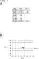
- FIGS. 7A and 7B each depict the finally extracted NDVI data of 6th, 7th, and 13th November.
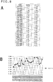
- FIG. 8B depicts vegetation change information which is generated by using all the NDVI data without having undergone extraction using ratio information. As depicted in FIG. 8B , the variation of NDVI values is greater, and the changing state of NDVI during the time period is difficult to observe.
- ratio information (total sunlight)/(scattered light)
- data for which an ambient light component ratio is around 1 is excluded at the aforementioned processing 1
- NDVI data for which an ambient light component ratio is sufficiently greater than 1 is extracted as a candidate at processing 2.
- Processing a and processing b are similar to the aforementioned processing 1 and processing 2.
- processing c the following conversion is executed.
- FIG. 10B depicts the extracted NDVI values (NDVI value before conversion).
- 4.0 is one example.
- the fixed value may be arbitrarily defined.
- the average value, the median value, the centroid value, or the like of the ratio information for the extracted NDVI may be used.
- converted NDVI value 0.0173 ⁇ ratio information value ⁇ 4.0 + NDVI .
- conversion can be executed so as to obtain a state where the ambient light component ratio is a fixed value of 4.0.
- Vegetation change information is generated by using the converted NDVI value.
- FIG. 11B depicts vegetation change information using the converted value.
- a vegetation change can be well discerned from the information. It can be seen that NDVI is improved by a certain reason (e.g. fetilization) around 14th November, for example.
- a certain reason e.g. fetilization
- the approximate curved line of the latter half of the time period is in a state of being shifted in the direction of an arrow D1 (upper right direction). This indicates an upward trend in the NDVI value.
- the approximate straight line is shifted in the direction of an arrow D2 (lower left direction)
- a downward trend of the NDVI values is indicated.
- FIGS. 13A, 13B and 13C each depict processing which is executed by the calculation section 10.
- FIG. 13A is considered to depict an example of NDVI calculation processing which is executed by the vegetation index calculation section 10A
- FIG. 13B is considered to depict an example of ambient light component ratio (ratio information) calculation processing which is executed by the ratio calculation section 10B
- FIG. 13C is considered to depict an example of the extraction and generation processing which is executed by the extraction section 10C, the generation section 10D, and the output control section 10E.
- step S100 the calculation section 10 acquires image data provided from the image capture device 250, and saves the image data in the storage section 12. That is, RED image data and NIR image data are acquired and saved.
- step S101 the calculation section 10 acquires ambient light data provided from the ambient light sensors 260A and 260B via the image capture device 250, and saves the ambient light data in the storage section 12.
- step S200 the calculation section 10 acquires ambient light data provided from the ambient light sensor 260A via the image capture device 250, and saves the acquired ambient light data in the storage section 12.
- step S201 the calculation section 10 acquires ambient light data provided from the ambient light sensor 260B via the image capture device 250, and saves the acquired ambient light data in the storage section 12. That is, the R, G, B detection values (E-RED, E-GREEN, E-BLUE) of scattered light are acquired and saved in order to calculate ratio information.
- the R, G, B detection values E-RED, E-GREEN, E-BLUE
- ratio information LA/LB may be obtained. That is, total sunlight/scattered light is obtained.
- step S300 the calculation section 10 associates the NDVI data generated by the processing in FIG. 13A with the ambient light component ratio data (ratio information) generated by the processing in FIG. 13B .
- the calculation section 10 executes processing of extracting NDVI for generating vegetation change information in step S301, and executes processing of generating vegetation change information in step S302.
- step S303 processing of controlling saving of the generated vegetation change information (e.g., the information in FIG. 9B or 11B ) in the storage section 12 or controlling output of the generated vegetation change information through the output section 13 is executed.
- the generated vegetation change information e.g., the information in FIG. 9B or 11B
- steps S301, S302 are depicted in FIGS. 14 and 15 .
- FIG. 14A is an example in which extraction is executed by the aforementioned (processing 1), (processing 2), and (processing 3).
- step S352 the calculation section 10 finally extracts multiple sets of NDVI data for which ratio information is determined to be close to one another, from among the NDVI data extracted as candidates (processing 3).
- This processing is executed while the NDVI data candidates are sequentially used as a reference, whereby temporary groups obtained by using the respective NDVI data as references are generated.
- the temporary groups all or some of temporary groups each including two or more (or a prescribed number or greater) sets of data are each set as a group of multiple sets of NDVI data for which ratio information is close to one another.
- a temporary group having the largest number sets of data, or n temporary groups in the descending order of the number of data may be each set as a group of multiple sets of NDVI data for which ratio information is close to one another.
- the threshold th2 may be changed to 0.02, for example, such that generating temporary groups is executed again.
- the calculation section 10 generates vegetation change information by using the multiple sets of finally extracted NDVI data. For example, vegetation change information such as that in FIG. 9B is generated.
- ratio information (total sunlight)/(scattered light)
- data for which the ambient light component ratio is around 1 is excluded in the aforementioned processing 1.
- a threshold th11 1.5 is set, and NDVI data for which ratio information ⁇ th11 is excluded.
- FIG. 14B is an example in which extraction and conversion are executed by the aforementioned (processing a), (processing b), and (processing c).
- step S360 the calculation section 10 obtains an approximate expression from the correlation between multiple sets of the DVI data extracted as candidates and the ratio information, and executes conversion with the ambient light component ratio adjusted to a fixed value.
- step S353 the calculation section 10 generates vegetation change information by using multiple sets of finally extracted NDVI data (converted values). For example, vegetation change information such as that in FIG. 11B is generated.
- FIGS. 15A and 15B depict other examples of the extraction processing.
- ratio information total sunlight/scattered light
- NDVI data for which ratio information is around 1 is extracted.
- step S371 the calculation section 10 generates vegetation change information by using the extracted NDVI data.
- vegetation change information suitable for time series observation can be generated only by observation data obtained in cloudy weather.
- FIG. 15B is an example in which the condition for the extraction processing can be variably set.
- step S380 the calculation section 10 sets an extraction condition.
- a condition for executing the extraction processing is set by a user's input using the input section 57 in FIG. 4 or the like.
- the extraction processing in FIG. 14A , the extraction processing in FIG. 14B , the extraction processing in FIG. 15A , or the like can be selected by a user.
- the calculation section 10 proceeds to S382 from step S381 to execute extraction of NDVI data in accordance with the set extraction condition.
- extraction of NDVI data is executed by any one of the extraction processing in FIG. 14A , the extraction processing in FIG. 14B , and the extraction processing in FIG. 15A .
- step S383 vegetation change information is generated by use of the extracted NDVI data.
- the calculation section 10 determines the type or properties of vegetation from a captured image, for example, and appropriate extraction processing is set in accordance with the determination result.
- FIG. 16 depicts various structure examples of the ambient light sensors 260.
- FIGS. 16B and 16C are an example in which, in the case where the ambient light sensors 260 are mounted on the upper surface of the flying body 200 as in FIG. 16A , the ambient light sensor 260A for measuring total sunlight and the ambient light sensor 260B for measuring scattered light are separated from each other and are installed in different sensor boxes SB.
- the sensor boxes SB herein refer to case body units including the ambient light sensors 260 and other devices.
- the light reception sections 261 are assumed to be provided on the upper surfaces of the respective sensor boxes SB.
- FIG. 16B is an example in which the pole-shaped light shielding body 262 is provided on the ambient light sensor 260B side, as in the aforementioned example in FIG. 1 .
- FIG. 16C is an example in which the arch-shaped light shielding body 262 is provided on the upper surface of the ambient light sensor 260B so as to cover the light reception section 261.
- FIGS. 16D and 16E are an example in which the ambient light sensors 260 for measuring total sunlight and scattered light are mounted on one sensor box SB.
- the ambient light sensors 260 two light reception sections 261A and 261B are provided on the upper surface of the sensor box SB, so as to be separated from each other in a diagonal direction.
- FIG. 16D is an example in which the roof-shaped light shielding body 262 is provided on the light reception section 261B side. Scattered light is detected on the light reception section 261 B side.
- a correction value for direct light varies depending on the difference in the incident angle of sunlight incident on the sensor boxes SB of the ambient light sensors 260. This situation is depicted in FIG. 12 .
- FIG. 17A is a top view of the sensor box SB provided with the ambient light sensor 260.
- a vector VA indicates a flying direction.
- FIG. 17A depicts an example in which the advancing direction is exactly the north.
- FIG. 17B is a side view of the sensor box SB.
- vector VB1, vector VB2 On the basis of roll, pitch, yaw values taken out from the IMU (inertia measuring device) mounted on the sensor box SB, two vectors (vector VB1, vector VB2) forming the upper surface of the sensor box SB are extracted. An exterior product of the two vectors is obtained, whereby a vector VH (a normal vector of the upper surface of the sensor box SB depicted in FIG. 17B ) orthogonal to the two vectors is obtained. Further, the sunlight is extracted as a vector VS (see FIG. 17B ) on the basis of the azimuth and attitude.
- the incident light ⁇ of the sunlight to the sensor box SB can be calculated by an expression of an outer product, represented by the following (expression 1) .
- the illumination obtained when a certain surface at a certain distance from a light source is illuminated becomes maximum when the surface is set to be perpendicular to the traveling direction of the light, and is reduced when the surface is tilted. That is, the illumination has a tendency of varying in proportion to the cosine (COS( ⁇ )) of the incident angle ⁇ . That is, the illumination has diagonal incident characteristics (cosine characteristics).
- direct light total sunlight
- FIG. 18 depicts an example of a flight plan of the flying body 200 for reliably detecting scattered light.
- the flying body 200 which flies above the farm field 210 in order to calculate vegetation indexes, repeats a motion of flying in a direction DA in the drawing, and flying in a direction DB by making a U turn or reversely flying in the direction DB upon reaching an end of the farm field 210.
- the ambient light sensors 260 need to well keep out from direct light of the sun 400.
- the light shielding body 262 depicted in each of FIGS. 16B to 16E needs to be rotated by 360 degrees.
- each solid line indicates the advancing direction of the flying body 200
- a broken line arrow HC indicates a one-and-half rotation motion of the flying body 200
- a broken line arrow CC indicates a one-rotation motion of the flying body 200.
- the flying body 200 sequentially makes one rotation.
- the control section provided to the flying body 200, the image capture device 250, or the ambient light sensor 260 determines, as the illumination value of scattered light, a minimum one of the illumination values acquired during a 360° rotation.
- the determined illumination value is associated, as a detection value of scattered light during this flight, with captured image data.
- the light shielding body 262 may be automatically or manually set on the basis of the flight plan and the clock time (the position of the sun 400) such that the light reception section 261 of the ambient light sensor 260 is shaded, or the attitude direction of the sensor box SB can be automatically or manually changed.
- attitude information in a case where the ambient light sensor 260 is mounted on the flying body 200 will be described.
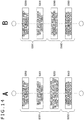
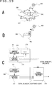
- FIG. 19A depicts the sensor box SB mounted on the flying body 200.
- FIG. 19B depicts a sensor box SBg which is set on the ground, for example, and includes the ambient light sensors 260.
- FIG. 19C depicts the configuration of the sensor boxes SB and SBg, and the signal processing section 310
- the ambient light sensor 260, the IMU 272 and a control section 273 are included in the ambient light sensors 260 in the sensor box SB mounted on the flying body 200.
- the ambient light sensor 260 and a control section 373 are included in the sensor box SBg set on the ground.
- the control section 273 acquires the detection value and the attitude information by accessing the ambient light sensor 260 and the IMU 272 at the same timing.
- the acquired data is transmitted directly or indirectly to the signal processing section 310. Corrected direct light is calculated by using the aforementioned incident angle ⁇ and elevation angle ⁇ .
- the signal processing section 310 can be implemented by an FPGA, or can be implemented by an external PC. In addition, this processing may be implemented by uploading the detection value and the attitude information to a cloud computing system.
- detection values of total sunlight and scattered light are regularly acquired by means of the sensor box SBg set on the ground, and the control section 373 transmits the detection values to the signal processing section 310.
- Information about the detection date and time is added to the detection values, and the detection values are collated with a time stamp when the image capture device 250 performs image capturing, whereby acquisition of detection values by the ambient light sensor 260 for a timing when the acquisition is difficult in the air can be interpolated.
- the information processing apparatus 1 includes the extraction section 10C that extracts, from a data group including vegetation data (e.g. NDVI data) of multiple time points respectively associated with ratio information which is a component ratio of ambient light, vegetation data for use by using the ratio information.
- vegetation data e.g. NDVI data
- ratio information which is a component ratio of ambient light
- the information processing apparatus 1 includes a generation section 10D that generates vegetation change information indicating a time series change of a vegetation state, by using the vegetation data extracted by the extraction section 10C.
- a data group in which vegetation data of each time point is associated with ratio information about an observation time of the data is set as an object to be processed, and vegetation data (NDVI data) suitable to be outputted is extracted on the basis of the ratio information.
- vegetation change information is generated.
- variation of the values of vegetation data becomes large due to the influence of ambient light.
- data that is suitable for the purpose of indicating a time series transition by using ratio information is extracted so that vegetation change information can be generated. That is, in the situation where variation of the values becomes large due to the influence of the weather or the like, vegetation data the value of which has fluctuated due to the influence of the weather is excluded so that vegetation change information properly presenting a time series change of vegetation can be generated. This is very useful for vegetation observation.
- NDVI has a tendency of including large errors and large fluctuations due to the weather.
- vegetation change information the values of which can be easily compared on the daily basis, as depicted in FIG. 9B or FIG. 11B , can be generated.
- ratio information is the value of the ratio of detection values of direct light and scattered light, or is the value of the ratio of detection values of total sunlight and scattered light.
- a light sensor set in a sunny position so as to be able to receive direct light in sunny weather, for example, direct light and scattered light are received so that the light amount of total sunlight can be detected.
- the light amount of scattered light can be detected.
- the light amount of direct light is obtained by subtracting the light amount of scattered light from the light amount of total sunlight.
- the value of the ratio of the detection value of direct light and the detection value of scattered light is almost “0" in cloudy weather or rainy weather.
- the value of the ratio of total sunlight and scattered light is almost “1” in cloudy weather or rainy weather. That is, the value of ratio information depends on the weather.
- Variation may become large between the value of vegetation information obtained from an image obtained in sunny weather and the value of vegetation information obtained from an image obtained in cloudy weather. Therefore, extraction according to the weather is executed on vegetation data of each time point by use of ratio information so that vegetation data obtained under the similar weather conditions can be collected.
- the extraction section 10C excludes, from vegetation data for use, vegetation data for which associated ratio information has a value determined to be around the specific value (e.g., around 0 or around 1) by comparison with the threshold th1 (S350 in FIGS. 14A, 14B ) has been described.
- extraction of vegetation data can be executed such that, from vegetation data for use in generation of vegetation change information, vegetation data obtained by observation in a specific weather is excluded.
- extraction of vegetation data can be executed such that vegetation data obtained by observation when there is no direct sunlight in cloudy weather (including a rainy weather) is excluded. Accordingly, vegetation change information in which the influence of the weather is reduced can be generated.
- the value "0” or “1” is set as the specific value, and vegetation data for which ratio information has a value sufficiently apart from the specific value is extracted as vegetation data for use (or a candidate thereof).
- vegetation data observed apparently in a non-cloudy state for example, can be extracted. Accordingly, vegetation data obtained under the similar ambient light conditions can be collected. This is also suitable for generation of vegetation change information in which the influence of the weather is reduced.
- the extraction section 10C executes processing of extracting multiple sets of vegetation data for which associated ratio information have respective values determined to close to one another by comparison with the threshold th2 (S352 in FIG. 14A ) has been described.
- ratio information which is a component ratio of ambient light is close to one another means that the state of ambient light at the observation time for calculating vegetation data is similar to one another.
- multiple sets of vegetation data for which ratio information is close to one another can be regarded as samples obtained at different time points but obtained under the similar ambient light states. Accordingly, vegetation data obtained under the similar ambient conditions can be collected. This is suitable for generation of vegetation change information in which the influence of the weather is reduced.
- the value "0” or “1” is set as the specific value, and vegetation data for which ratio information has a value around the specific value is extracted as vegetation data for use (or a candidate thereof).
- vegetation data obtained by observation in a specific ambient light state e.g., cloudy weather
- vegetation data obtained under the similar ambient light conditions can be collected. This is also suitable for generation of vegetation change information in which the influence of the weather is reduced.
- vegetation data for use can be extracted through selection of various conditions.
- the extraction condition can be variably set by a user's operation, for example, a user can extract an arbitrary weather state to generate vegetation change information.
- the generation section 10D converts the vegetation data extracted by the extraction section 10C to a value with the ratio information adjusted to a fixed value, and generates vegetation change information by using the converted vegetation data (S360 and S353 in FIG. 14B ) has been described.
- the information processing apparatus 1 includes the vegetation data calculation section 10A that calculates vegetation data by using vegetation observation data (e.g., captured image data) of each time point (see FIG. 3 ) has been described.
- vegetation observation data e.g., captured image data
- vegetation data such as NDVI data can be acquired, and it is sufficient to acquire only captured image data from the image capture device 250. Accordingly, no particular device load is generated on an observation device side using the flying body 200, etc.
- the vegetation data calculation section 10A obtains an NDVI value as the vegetation data.
- NDVI is an index indicating the distribution condition or activity of vegetation. Generation of vegetation change information as information indicating a time series change of NDVI, is useful in observing a change of the vegetation state.
- the information processing apparatus 1 includes the ratio calculation section 10B that calculates ratio information which is a component ratio of ambient light so as to correspond to vegetation data of each time point, by using a detection value of ambient light at the time point (see FIG. 3 ) has been described.
- the ratio calculation section 10B is included in the information processing apparatus 1 so as to obtain ratio information.
- the processing by the extraction section and the generation section can be executed by acquisition of the detection value of the ambient light sensor 260. Therefore, no particular device load is generated to the observation device side using the flying body 200 or the like.
- the ratio calculation section 10B calculates ratio information by using detection values of the respective light reception sections 261 obtained by the ambient light sensor 260 including the light reception section 261 on which the light shielding body 262 casts a shadow and the light reception section 261 which does not come under the influence of the light shielding body 262 (see FIGS. 2 and 16 ), has been described.
- the structure having the light shielding body 260 With the structure having the light shielding body 260, detection of direct light and scattered light is properly carried out by use of the ambient light sensors 260 mounted on the flying body 200. Therefore, in the information processing apparatus 1, the accuracy of ratio information can be made high and vegetation data can be appropriately extracted.
- NDVI has been described as an example of vegetation data.
- various types of a vegetation index to be used as vegetation data can be adopted. Examples thereof include
- PRI is obtained by converting, into an index form, a spectral reflectivity which varies in accordance with deepoxidation in a xanthophyll cycle.
- a xanthophyll cycle is a mechanism, such as stomata closing caused by strong light or water stress, for discharging, as heat, excess optical energy which cannot be converted by photosynthesis.
- R570 represents the intensity of reflection light having a wavelength of 570 nm
- R531 represents the intensity of reflection light having a wavelength of 531 nm.
- the intensity of chlorophyll fluorescence may be the intensity of chlorophyll fluorescence (solar-induced chlorophyll fluorescence (SIF)) that is excited by sunlight.
- SIF solar-induced chlorophyll fluorescence
- the chlorophyll fluorescence may be excited not by sunlight but by a laser or an LED.
- a chlorophyll fluorescence index is represented by the ratio of two wavelengths such as two wavelengths of 685 nm and 735 nm, through measurement of chlorophyll fluorescence separately by a few wavelengths.
- Chlorophyll fluorescence is generated from a plant in association with photosynthesis of the plant, and is a phenomenon in which, if energy is not extracted within a certain time period from a reaction center where electrons are excited by light, the energy is emitted as fluorescence having a wavelength around 680 to 770 nm in higher plants.
- Emitted energy is 0.5% to 3% of the energy of input light, varies depending on the state of photosynthesis of the plant, and becomes large in a case, such as stomata closing caused by water stress or strong light, where the amount of excess optical energy which cannot be converted by photosynthesis is large.
- An object to be observed is vegetation in the farm field 210.
- the present technique is applicable to vegetation observation of lawn on an athletic field such as a soccer field or a baseball field, and vegetation observation in a natural grassland, a forest land, and a primary forest, etc., for example.
- the configuration having described in the embodiment is one example.
- the calculation section 10 may be mounted on the flying body 200. Further, a microcomputer in the image capture device 250 may function as the calculation section 10. In addition, a microcomputer may be mounted in the sensor box SB including the ambient light sensor 260 so as to function as the calculation section 10.
- Detection of total sunlight and scattered light may be executed only by the ambient light sensor 260 set on the ground without using the ambient light sensor 260 mounted on the flying body 200.
- the program according to the embodiment of the present invention causes the CPU 51 of the computer device 150 to execute the extraction step (S301) of extracting, from a data group including vegetation data of multiple time points respectively associated with ratio information which is a component ratio of ambient light, vegetation data for use by using the ratio information.
- the program causes the CPU 51 of the computer device 150 to execute the extraction step (S301), and the generation step (S302) of generating vegetation change information indicating a time series change of the vegetation state by using the vegetation data extracted at the extraction step.
- the program causes the CPU 51 of the computer device 150 to execute the processing in FIG. 13C ( FIG. 14 , FIG. 15 ).
- the information processing apparatus 1 according to the present embodiment can be easily implemented.
- Such a program can be preliminarily stored in a recording medium included in a device such as a computer device, or in a ROM in a CPU-equipped microcomputer, etc.
- a program can be temporarily or permanently saved (stored) in a removable recoding medium such as a semiconductor memory, a memory card, an optical disk, a magneto-optical disk, or a magnetic disk.
- a removable recording medium can be provided as so-called package software.
- such a program can be installed from the removable recording medium into a personal computer or the like, or can be installed from a download website over a network such as a LAN or the internet.
Landscapes
- Physics & Mathematics (AREA)
- Engineering & Computer Science (AREA)
- General Physics & Mathematics (AREA)
- Spectroscopy & Molecular Physics (AREA)
- Theoretical Computer Science (AREA)
- Computer Vision & Pattern Recognition (AREA)
- Health & Medical Sciences (AREA)
- Life Sciences & Earth Sciences (AREA)
- Multimedia (AREA)
- General Health & Medical Sciences (AREA)
- Quality & Reliability (AREA)
- Immunology (AREA)
- Biochemistry (AREA)
- Pathology (AREA)
- Remote Sensing (AREA)
- Analytical Chemistry (AREA)
- Chemical & Material Sciences (AREA)
- Mathematical Physics (AREA)
- Sustainable Development (AREA)
- Investigating Or Analysing Materials By Optical Means (AREA)
- Image Processing (AREA)
- Image Analysis (AREA)
- Management, Administration, Business Operations System, And Electronic Commerce (AREA)
- Information Retrieval, Db Structures And Fs Structures Therefor (AREA)
Abstract
Description
- The present technique relates to an information processing apparatus, an information processing method, a program, and an information processing system, and particularly, to a technique suitable for generation of vegetation change information which presents a change of a vegetation state.
- For example, an attempt to perform remote sensing on the vegetation state of plants by capturing an image of the vegetation state while moving, above a farm field, a small flying body having an image capture device mounted thereon, has been made.
-
PTL 1 discloses a technique of capturing an image of a farm field and performing remote sensing. - [PTL 1]
Japanese Patent No.5162890 - A vegetation index can be measured from a captured image of vegetation in a farm field. For example, when vegetation indexes are obtained from daily captured images, vegetation change information indicating a time series change of the vegetation state can be generated. For example, as vegetation indexes, NDVIs (Normalized Difference Vegetation Indexes) are obtained and arranged in time series so that a change of the vegetation state can be confirmed.
- However, regarding vegetation indexes such as NDVIs, value fluctuations are caused by a difference in condition such as weather (clear/cloudy). Accordingly, even when confirming a daily change of NDVI is desired, for example, vegetation change information in which NDVIs are arranged in time series, includes value fluctuations caused by the weather. Therefore, even if taking a look at the vegetation change information, a worker, etc., cannot correctly discern a daily change of the vegetation.
- Therefore, an object of the present technique is to make it possible to generate vegetation change information that is less likely to come under the influence of a condition such as weather, and to make it possible to properly present a time series change of a vegetation state.
- An information processing apparatus according to the present technique includes
an extraction section that extracts, from vegetation data of multiple time points respectively associated with ratio information which is a component ratio of ambient light, at least a part of the vegetation data on the basis of the ratio information. - That is, a data group including vegetation data of the time points associated with the component ratio (ratio information) of ambient light at the corresponding observation times, is an object to be processed. In this case, vegetation data that is suitable to be outputted is extracted on the basis of the ratio information.
- Further, the information processing apparatus includes a generation section that generates, by using the vegetation data extracted by the extraction section, vegetation change information indicating a time series change of the vegetation data.
- That is, vegetation change information is generated by use of the vegetation data that is suitable to be outputted and that has been extracted by the extraction section on the basis of the ratio information.
- In the information processing apparatus, the ratio information may be a value of a ratio of a detection value of direct light and a detection value of scattered light, or is a value of a ratio of a detection value of total sunlight and a detection value of scattered light.
- For example, direct light is a light component (so-called direct sunlight) having directly come from a light source such as the sun, and scattered light is light scattered by molecules and cloud particles in the atmosphere. The sum of direct light and scattered light is total sunlight.
- In the information processing apparatus, the extraction section may execute processing of excluding, from vegetation data for use, vegetation data for which associated ratio information has a value determined to be around a specific value by comparison with a threshold.
- For example, in a case where the ratio information is (direct light)/(scattered light), the ratio information is around 0 in cloudy weather.
- For example, in a case where the ratio information is (total sunlight)/(scattered light), the ratio information is around 1 in cloudy weather. The value "0" or "1" is set as the specific value, and vegetation data for which ratio information has a value equal to or around the specific value, is excluded.
- In the information processing apparatus, the extraction section may execute processing of extracting vegetation data for which associated ratio information has a value different from a specific value by at least a prescribed amount.
- For example, in a case where the ratio information is calculated such that the ratio information becomes "0" or "1" in cloudy weather, the value "0" or "1" is set as the specific value, and vegetation data for which the ratio information is sufficiently apart from the specific value is extracted as vegetation data for use (or a candidate thereof).
- In the information processing apparatus, the extraction section may execute processing of extracting multiple sets of vegetation data for which associated ratio information have respective values determined to be close to one another by comparison with a threshold.
- The situation in which the ratio information which is a component ratio of ambient light is close to one another, means that the states of ambient light at observation times for calculating vegetation data are similar to one another.
- In the information processing apparatus, the extraction section may execute processing of extracting vegetation data for which associated ratio information has a value determined to be around a specific value by comparison with a threshold.
- For example, in the case where ratio information is calculated such that the ratio information becomes "0" or "1" in cloudy weather, the value "0" or "1" is set as the specific value, and vegetation data for which ratio information is around the specific value is extracted as vegetation data for use (or a candidate thereof).
- In the information processing apparatus, an extraction condition for the extraction processing by the extraction section may be variably set.
- For example, for the extraction processing such as excluding vegetation data for which ratio information is close to the specific value, extracting vegetation data for which ratio information is sufficiently apart from the specific value, extracting multiple sets of vegetation data for which ratio information are close to one another, and extracting vegetation data for which ratio information is close to the specific value, the condition can be variably set.
- In the information processing apparatus, the generation section may convert the vegetation data extracted by the extraction section, to a value with the ratio information adjusted to be fixed, and may generate vegetation change information by using the converted vegetation data.
- For example, vegetation change information is generated by use of vegetation data for which extracted ratio information are close to one another. The vegetation data is converted so as to achieve a state where the value of the ratio information is fixed.
- The information processing apparatus may include a vegetation data calculation section that calculates vegetation data by using vegetation observation data of each time point.
- That is, vegetation data of each time point is generated in the information processing apparatus.
- In the information processing apparatus, the vegetation data calculation section may obtain an NDVI value as the vegetation data.
- That is, an NDVI value which is a vegetation index is obtained, and the vegetation change information as the change of the NDVI is generated.
- The information processing apparatus may include a ratio calculation section that calculates ratio information which is a component ratio of ambient light, so as to correspond to the vegetation data of each time point by using a detection value of ambient light at the time point.
- That is, ratio information corresponding to vegetation data of each time point is generated in the information processing apparatus. The ratio information is calculated by use of a light detection value obtained at substantially the same time point as that of a detection value used for generation of vegetation data.
- In the information processing apparatus, the ratio calculation section may calculate the ratio information by using detection values obtained by an ambient light sensor including a light reception section on which a light shielding body casts a shadow and the light reception section which does not come under an influence of the light shielding body, the detection values being obtained at the respective light reception sections.
- By use of the ambient light sensor mounted on a flying body, direct light and scattered light can be detected with the light shielding body.
- An information processing method according to the present technique includes
executing, by means of an information processing apparatus, processing of extracting, from a data group including vegetation data of multiple time points respectively associated with ratio information which is a component ratio of ambient light, vegetation data for use by using the ratio information. Accordingly, vegetation data for generating vegetation change information that is less likely to come under the influence of the environmental condition can be extracted in the information processing apparatus. - A program according to the present technique is for causing a computer device to execute processing of extracting, from a data group including vegetation data of multiple time points respectively associated with ratio information which is a component ratio of ambient light, vegetation data for use by using the ratio information. Accordingly, a computer device that extracts vegetation data for generating vegetation change information that is less likely to come under the influence of the environmental condition can be easily implemented.
- An information processing system according to the present technique includes an ambient light sensor including a light reception section on which a light shielding body casts a shadow and a light reception section which does not come under an influence of the light shielding body, the ratio calculation section, the extraction section, and the generation section. Accordingly, a system suitable for generation of vegetation change information that is less likely to come under the influence of the environmental condition, can be constructed.
- The present technique provides an effect that vegetation change information in which a fluctuation due to a condition such as weather is less likely to appear and a time series change of a vegetation state can be properly presented, can be generated.
- Note that the effect described herein is not limited, and any of the effects disclosed in the present description may be provided.
-
- [
FIG. 1 ]
FIG. 1 is an explanatory diagram of a state in which an image of a farm field is captured according to an embodiment of the present technique. - [
FIG. 2 ]
FIG. 2 is a block diagram of an image capture device and ambient light sensors according to the embodiment. - [
FIG. 3 ]
FIG. 3 is a block diagram of an information processing apparatus according to the embodiment. - [
FIG. 4 ]
FIG. 4 is a block diagram of a computer device that can be used in the embodiment. - [
FIG. 5 ]
FIG. 5 is a transition diagram of a photosynthesis photon flux density and NDVI obtained through observation in a sunny area and a shaded area. - [
FIG. 6 ]
FIG. 6 is an explanatory diagram of examples of ratio information and NDVI obtained by measurement. - [
FIG. 7 ]
FIG. 7 is an explanatory diagram of extraction processing according to the embodiment. - [
FIG. 8 ]
FIG. 8 is an explanatory diagram of vegetation change information generated without undergoing extraction processing. - [
FIG. 9 ]
FIG. 9 is an explanatory diagram of vegetation change information generated through the extraction processing according to the embodiment. - [
FIG. 10 ]
FIG. 10 is an explanatory diagram of conversion of NDVI values according to the embodiment. - [
FIG. 11 ]
FIG. 11 is an explanatory diagram of vegetation change information generated through the extraction processing and conversion processing according to the embodiment. - [
FIG. 12 ]
FIG. 12 is an explanatory diagram of an example of collinear approximation during conversion of NDVI values according to the embodiment. - [
FIG. 13 ]
FIG. 13 is a flowchart of a processing example according to the embodiment. - [
FIG. 14 ]
FIG. 14 is a flowchart of an example of the extraction processing and generation processing according to the embodiment. - [
FIG. 15 ]
FIG. 15 is a flowchart of an example of the extraction processing and generation processing according to the embodiment. - [
FIG. 16 ]
FIG. 16 is an explanatory diagram of a structure example of the ambient light sensors according to the embodiment. - [
FIG. 17 ]
FIG. 17 is an explanatory diagram of an incident angle to an ambient light sensor according to the embodiment. - [
FIG. 18 ]
FIG. 18 is an explanatory diagram of a scheme for acquiring scattered light according to the embodiment. - [
FIG. 19 ]
FIG. 19 is an explanatory diagram of a scheme for acquiring total sunlight and scattered light according to the embodiment. - Hereinafter, an embodiment will be explained in accordance with the following order.
- <1. Configuration of System and Devices>
- <2. Extraction Processing Using Ratio information>
- <3. Conversion Processing of Vegetation Index Using Ratio Information>
- <4. Processing Examples>
- <5. Various Examples Regarding Light Detection Using Ambient Light Sensors>
- <6. Conclusion and Modification>
- An embodiment will be explained with use of, as an example, a case where sensing of the vegetation state of a farm field is performed.
- As depicted in
FIG. 1 , remote sensing regarding vegetation in afarm field 210 is performed, for example, every day by use of animage capture device 250 mounted on a flyingbody 200. By use of vegetation data (e.g. vegetation index data) obtained by the daily observation, vegetation change information indicating a time series change of the vegetation state is generated by aninformation processing apparatus 1. An explanation will be given of this case as an example. -
FIG. 1 depicts a state of thefarm field 210. - The flying
body 200 which is compact can move above thefarm field 210 by operator's wireless control or wireless automatic control, for example. - In the flying
body 300, theimage capture device 250 is set so as to capture images of an area under the device, for example. When the flyingbody 200 is moving along a prescribed route above thefarm field 210, theimage capture device 250 regularly captures stationary images or captures a video image, for example so that an image of a range W of the image capture visual field at each time point can be obtained. - Various types of image capture devices may be used as the
image capture device 250. - For example, an image file (image captured at a certain time point) obtained by image capturing performed by the
image capture device 250 may include a spectroscopic measurement image. That is, a multi-spectrum camera may be used as theimage capture device 250, and images to be captured thereby may include a measurement image including information two or more specific wavelength regions. - Also, a camera that captures an image of R (red), G (green), and B (blue) visible light may be used as the
image capture device 250. - Also, a camera for obtaining captured images of a red wavelength region (RED) and a near infrared region (NIR: Near Infra RED) such that NDVI can be calculated from the obtained images, may be used as the
image capture device 250. NDVI refers to an index indicating the distribution condition or activity level of vegetation. - Hereinafter, an explanation will be given on the assumption that a camera capable of obtaining captured images of a red wavelength region (RED) and a near infrared region (NIR) is used as the
image capture device 250. - In addition, tag information is added to an image obtained by image capturing performed by the
image capture device 250. The tag information includes image capture date-and-time information, positional information (latitude/longitude information) as GPS (Global Positioning System) data, image capturing device information (identification information or model information about the camera, etc.), information about image data (information about an image size, a wavelength, image capturing parameters, and the like), and the like. - In the present embodiment, not only the
image capture device 250 but also ambientlight sensors 260 are mounted on the flyingbody 200. In the example inFIG. 1 , twoambient light sensors body 200. - Note that, to collectively refer to one or more ambient light sensors for use, an expression "ambient
light sensors 260" is used. - The
ambient light sensors light reception section 261 provided on the upper surface side thereof, so as to detect light. With this configuration, the level (the illumination, the photosynthetic photon flux density (hereinafter, referred to as "PPFD"), etc.) of ambient light the light source of which issun 400, can be detected. - Note that the PPFD refers to a photosynthetic photon flux density only in a wavelength region of 400 to 700 nm where chlorophyll can be absorbed.
- The light amount of total sunlight and the light amount of scattered light can be detected from detection values obtained by the
ambient light sensors - Outdoor ambient light is generally expressed by (total sunlight) = (direct light) + (scattered light).
- Direct light refers to so-called direct sunlight from the
sun 400. - Scattered light refers to light scattered by molecules and cloud particles in the atmosphere other than the direct sunlight.
- Total sunlight is total light from the whole sky, and also is the sum of direct light and scattered light.
- Nothing for shielding sunlight is provided to the ambient
light sensor 260A. Thus, the ambientlight sensor 260A receives both direct light and scattered light. Therefore, the illuminance, etc. of total sunlight can be detected by the ambientlight sensor 260A. - A pole-shaped
light shielding body 262 is protrudingly provided on the upper surface of the ambientlight sensor 260B. Thelight shielding body 262 casts a shadow SDW on thelight reception section 261. As a result, thelight reception section 261 receives no direct light. Therefore, the illumination, etc. of scattered light is detected by the ambientlight sensor 260B. - Regarding direct light, the illumination thereof can be obtained by subtracting the detection value obtained by the ambient
light sensor 260B from the detection value obtained by the ambientlight sensor 260A. - Sensors that each detect the illuminations of R (red), G (green), B (blue), NIR (near infrared light) as ambient light may be used as the
ambient light sensors - That is, detection values of R, G, B, IR (E-RED, E-GREEN, E-BLUE, E-NIR) of total sunlight can be obtained by the ambient
light sensor 260A, and detection values of R, G, B, IR (E-RED, E-GREEN, E-BLUE, E-NIR) of scattered light can be obtained by the ambientlight sensor 260B. - Note that tag information is added to the detection values obtained by the
ambient light sensors - The reason why the pole-shaped
light shielding body 262 is provided on the ambientlight sensor 260B, is that thelight reception section 261 is desirably shielded from only direct sunlight, if possible. In other words, thelight reception section 261 is preferably shielded at a pin point only from thesun 400. The reason for this is that wide light shielding results in shielding of even a part of scattered light so that the accuracy of detection at a scattered light level may be deteriorated or the values may be varied. - Image data and detection values obtained by the
image capture device 250 and the ambientlight sensors 260 mounted on the flyingbody 200 are transmitted to theinformation processing apparatus 1. Theinformation processing apparatus 1 generates vegetation change information indicating a time series change of the vegetation state, by using the image data and the detection values. Specifically, in the present embodiment, an example in which vegetation change information indicating a time series change of NDVI is generated will be explained. The present embodiment is configured to be able to provide vegetation change information in a state where a fluctuation of an NDVI value due to the influence of the weather, particularly, is suppressed. - The
information processing apparatus 1 is implemented as a PC (personal computer) or an FPGA (field-programmable gate array), for example. - Note that the
information processing apparatus 1 is a separated from theimage capture device 250 inFIG. 1 . However, a computation device (e.g. microcomputer) serving as theinformation processing apparatus 1 may be provided in a unit including theimage capture device 250. -
FIG. 2 depicts a configuration example of theimage capture device 250. - The
image capture device 250 includes animage capture section 31, asignal processing section 32, acontrol section 33, astorage section 34, acommunication section 35, aposition detection section 36, and aclock section 37. - The
image capture section 31 includes an image capture lens system, an exposure part, a filter, and an image sensor, etc., and outputs a captured image signal as an electric signal upon receiving subject light. - That is, in the
image capture section 31, light (reflection light) from a subject such as an object to be measured, is incident on the image sensor via the lens system and the filter. - The lens system refers to an incident optical system including various lenses such as an incident end lens, a zoom lens, a focus lens, and a condensing lens.
- The filter refers to a filter for taking out a wavelength to be measured of an object to be measured. This refers to a color filter commonly formed on an image sensor, a wavelength filter commonly disposed forward of an image sensor, or the like.
- The exposure part refers to a part, of the image sensor, where exposure control is performed by adjustment of the opening amount of an optical system such as a lens system, an iris (aperture), and the like such that sensing is performed in the state where a signal charge falls within a dynamic range without being saturated.
- The image sensor is formed so as to have, on a sensor surface thereof, a sensing element in which a plurality of pixels is two-dimensionally arranged by a repeated pattern.
- The image sensor detects light having passed through the filter by means of a sensing element, and outputs a captured image signal corresponding to the light amount of light to the
signal processing section 32. - The
signal processing section 32 performs AGC processing, A/D conversion processing, and the like on the captured image signal outputted from the image sensor of theimage capture section 31 so as to convert the captured image signal to digital data, further performs various necessary signal processing on the digital data, and outputs, to thecontrol section 33, the resultant data as image data on an object to be measured. - When it is assumed that captured images of a red wavelength region (RED) and a near infrared region (NIR) are obtained as the image data on an object to be measured, the
signal processing section 32 generates RED image data and NIR image data, and outputs the generated data to thecontrol section 33. - The
control section 33 includes a microcomputer, for example, and controls the overall operation of theimage capture device 250, such as an image capture operation, an image data storing operation, and a communication operation. - The
control section 33 executes processing of sequentially storing, in thestorage section 34, RED image data and NIR image data supplied from thesignal processing section 32. When doing so, thecontrol section 33 adds tag information to the RED image data and the NIR image data, makes an image file of the resultant data, and stores the file in thestorage section 34. - For example, the
control section 33 associates the RED image data and the NIR image data of each time point with the positional information obtained by theposition detection section 36 and the time-and-date information obtained by theclock section 37, and makes a file of the resultant data. Note that theposition detection section 36 includes a GPS receptor, for example, and supplies, as the positional information, information about the latitude and longitude to thecontrol section 33. - In addition, the
control section 33 adds the aforementioned image capture device information and information about the image data. - Accordingly, regarding the RED image data and the NIR image data stored in the
storage section 34, information about the position and the data and time of image capturing, the data type, and the type of the image capture device, and the like can be recognized at an external device such as theinformation processing apparatus 1. - In the example in
FIG. 2 , the detection values obtained by theambient light sensors control section 33 of theimage capture device 250. - The
control section 33 causes thestorage section 34 to sequentially store detection values obtained by theambient light sensors - Further, the
control section 33 adds the positional information and the date-and-time information at the detection time to the first ambient light data and the second ambient light data by using the positional information from theposition detection section 36 and the date-and-time information from theclock section 37, and causes thestorage section 34 to store the resultant data. Therefore, regarding the first ambient light data and the second ambient light data stored in thestorage section 34, information about the position and the date and time of image capturing can be recognized at an external device such as theinformation processing apparatus 1. - Note that, in the case where the
ambient light sensors light sensor 260A is total sunlight data. On the other hand, the second ambient light data which is a detection value obtained by the ambientlight sensor 260B having thelight reception section 261 on which thelight shielding body 262 casts the shadow SDW is scattered light data. - For example, a flash memory which is an internal memory of the
image capture device 250 or a portable memory card is used as thestorage section 34. Another type of a storage medium also may be used. - The
communication section 35 performs transmission and reception of data with an external device via wired or wireless communication. For example, wired communication based on the USB (Universal Serial Bus) standard or the like may be performed, or communication based on a wireless communication standard such as the Bluetooth (registered trademark) or the WI-FI (registered mark) may be performed. - In any case, the RED image data, the NIR image data, the first ambient light data, and the second ambient light data stored in the
storage section 34 can be transferred by thecommunication section 35 to an external device such as theinformation processing apparatus 1. - Note that, in a case where a portable memory card or the like is used as the
storage section 34, the data stored therein may be delivered to theinformation processing apparatus 1 or the like through delivery of a recording medium such as the memory card. - Next, the configuration of the
information processing apparatus 1 will be explained with reference toFIG. 3 . -
FIG. 3 depicts the functional configuration of theinformation processing apparatus 1 as the present embodiment. As depicted inFIG. 3 , theinformation processing apparatus 1 includes acalculation section 10, acommunication section 11, astorage section 12, and anoutput section 13. - The
communication section 11 is configured to be able to perform transmission and reception of data with at least thecommunication section 35 of theimage capture device 250 via wired or wireless communication. Over the communication performed by thecommunication section 11, theinformation processing apparatus 1 can acquire the RED image data, the NIR image data, the first ambient light data, and the second ambient light data stored in thestorage section 34 of theimage capture device 250. For example, theinformation processing apparatus 1 may receive and acquire the data by sequentially performing wireless communication while theimage capture device 250 is capturing images, or may collectively receive and acquire the data of each time point after image capturing is completed. - The
storage section 12 stores the RED image data, the NIR image data, the first ambient light data, and the second ambient light data acquired by thecommunication section 11. Note that, in a case where a memory card slot or the like is provided to have a drive of a storage medium shared with theimage capture device 250, the storage medium such as the memory card used in theimage capture device 250 may directly function as thestorage section 12, or the data may be transferred from the storage medium shared with theimage capture device 250, and be stored in the internal storage medium (storage section 12) of theinformation processing apparatus 1. - The
calculation section 10 includes aCPU 51 which will be explained later with reference toFIG. 4 . As functional parts to be implemented by a program started in the calculation section 10 (CPU 51), a vegetationindex calculation section 10A, aratio calculation section 10B, anextraction section 10C, ageneration section 10D, and anoutput control section 10E are provided. - The vegetation
index calculation section 10A calculates vegetation data by using the RED image data and the NIR image data taken into thestorage section 12, that is, vegetation observation data. The calculated vegetation data is stored, as vegetation data on the date and time/position of the observation data, in thestorage section 12. - Specifically, the vegetation
data calculation section 10A obtains, as the vegetation data, an NDVI value which is one of vegetation indexes. - By use of the stored RED image data and NIR image data, NDVI is calculated by

- Note that total sunlight data is acquired as the first ambient light data, and scattered light is acquired as the second ambient light data. The NDVI may be corrected with use of a red detection value E-RED and a near-infrared light detection value E-NIR of the total sunlight acquired at a time the same (or substantially the same) as the acquisition time of the RED image data and the NIR image data.
- That is, with a reference coefficient defined as α,


- The vegetation
index calculation section 10A executes processing of obtaining NDVI of each time point by the above calculation. NDVI of each time point is saved in thestorage section 12. - The
ratio calculation section 10B calculates ratio information which is a component ratio of ambient light so as to correspond to the vegetation data (NDVI) of each time point, by using a detection value of the time point. - The component ratio of ambient light is the ratio of components which are included (are decomposable) in the ambient light (e.g., the illumination ratio of the components).
- In this case, a component ratio of ambient light is the ratio of total sunlight and scattered light, or is the ratio of direct light and scattered light. That is,


- In addition, the detection values include detection values E-RED, E-GREEN, E-BLUE, E-NIR of R, G, B, IR, and, for example, the G detection value E-GREEN is used for calculation of the ratio information. For example,

- Alternatively, the illumination by use of the value of detection values (E-RED) + (E-GREEN) + (E-BLUE) and may be obtained, and then, the ratio information may be obtained by

- The ratio information calculated by any of the aforementioned methods, is saved, in the
storage section 12, in association with NDVI of the corresponding the date and time/position. - The
extraction section 10C extracts, from a data group including NDVI of multiple time points respectively associated with ratio information which is the ratio component of ambient light, vegetation data for use by using the ratio information. - That is, the NDVI of each time point is obtained and saved by the vegetation
index calculation section 10A, and the NDVI of each time point is associated with the ratio information obtained by theratio calculation section 10B. Accordingly, a data group including NDVI of the time points during a certain time period is formed in thestorage section 12. Theextraction section 10C executes processing of extracting NDVI for use in generation of vegetation change information from the data group by referring to the ratio information. - Note that extraction of a part of the NDVI of each time point is not particularly needed. When being arranged, all the NDVI can be used as vegetation change information indicating a time series change of NDVI. However, in this case, due to the influence of weather, even an NDVI value that is not so appropriate for time series observation is included. The present embodiment attempts to extract NDVI appropriate for time series observation, and to create vegetation change information by using the NDVI.
- The
generation section 10D generates vegetation change information indicating a time series change of the vegetation state, by using the NDVI data extracted by theextraction section 10C. That is, thegeneration section 10D generates information from which a vegetation change can be observed, by arranging the extracted NDVI in time series. - The
output control section 10E controls output of the vegetation change information generated by thegeneration section 10D. Specifically, theoutput control section 10E executes processing of storing the vegetation change information during a certain time period in thestorage section 12, or supplying the vegetation change information to theoutput section 13 so as to output the vegetation change information therethrough. - The
output section 13 outputs vegetation change information IFT generated by thecalculation section 10. - For example, the
output section 13 serves as a display output section to supply the vegetation change information IFT in a form of image data to a display device, so that display output is performed. - Alternatively, for example, the
output section 13 serves as a printing control section to supply the vegetation change information IFT in a form of printing information, to a printer device, so that printing output is performed. - Alternatively, for example, the
output section 13 serves as an external-device communication section to transmit the vegetation change information IFT to an external device. - Although a specific processing example will be explained later, the calculation section 10 (or the
information processing apparatus 1 including the calculation section 10) has at least the function of theextraction section 10C by hardware or software in the configuration inFIG. 3 , and thus, corresponds to the information processing apparatus set forth in the claims. - Also, the
information processing apparatus 1 can be implemented by a PC (personal computer), an FPGA (field-programmable gate array), or the like. - Further, in the aforementioned configuration, the vegetation
index calculation section 10A and theratio calculation section 10B are included in theinformation processing apparatus 1 side. However, these sections may be provided in thecontrol section 33 of theimage capture device 250 such that NDVI and ratio information in a state of being able to be associated with each other may be transmitted from theimage capture device 250 to theinformation processing apparatus 1. - Moreover, the functions of the
extraction section 10C and thegeneration section 10D may also be provided in thecontrol section 33 of theimage capture device 250 such that the vegetation change information IFT can be outputted by theimage capture device 250. In this case, theimage capture device 250 corresponds to the information processing apparatus set forth in the claims. - Next, a hardware configuration example (computer device 150) of the
information processing apparatus 1 implemented by a PC or the like in the present embodiment will be explained with reference toFIG. 4 . - As depicted in
FIG. 4 , thecomputer device 150 includes the CPU (Central Processing Unit) 51, a ROM (Read Only Memory) 52, and a RAM (Random Access Memory) 53. - The
CPU 51 executes various processing in accordance with a program stored in theROM 52 or a program loaded from arecording section 59 into theRAM 53. TheRAM 53 further records data necessary for theCPU 51 to execute the various processing, and the like, as appropriate. - The
CPU 51, theROM 52, and theRAM 53 are mutually connected via abus 54. An input/output interface 55 is also connected to thebus 54. - A
display 56 includes a liquid crystal panel, an organic EL (Electroluminescence) panel, or the like, aninput section 56 includes a keyboard, a mouse, or the like, aloudspeaker 58, therecording section 59 includes an HDD (Hard Disk Drive) or the like, and acommunication section 60, etc., can be connected to the input/output interface 55. - The
display 56 may be integrated with thecomputer device 150 or may be a separated device. For example, a captured image or a composite image is displayed, or an evaluation index is displayed. - The
input section 57 means an input unit which is used by a user using thecomputer device 150. - The
communication section 60 executes communication processing over networks including the internet, or executes communication with peripheral devices. - A
drive 61 may also be connected to the input/output interface 55, if needed. Amemory card 62 may be attached thereto. A computer program read out from thememory card 62 may be installed into therecording section 59, if needed, or data processed at theCPU 51 is recorded in therecording section 59. Obviously, a recording and reproducing drive for a removable recording medium such as a magnetic disk, an optical disk, or a magneto-optical disk, may be used as thedrive 61. - With this hardware configuration, processing to be performed by the
information processing apparatus 1 according to the embodiment, or processing to be performed by theextraction section 10C and thegeneration section 10D, and further processing to be performed by the vegetationindex calculation section 10A, theratio calculation section 10B, and theoutput control section 10E can be executed. That is, these processing can be implemented by software which is started at theCPU 51. A program constituting the software is installed into thecomputer device 150 inFIG. 4 by being downloaded from a network or being read out from a removable recording medium. Alternatively, the program may be preliminarily stored in an HDD or the like serving as therecording section 59. Upon start of the program at theCPU 51, the functions of the aforementioned sections are implemented. - Note that the
information processing apparatus 1 according to the embodiment is not limited to the single computer device (information processing apparatus) 150 having the hardware configuration as depicted inFIG. 4 , and may be configured by a system of a plurality of computer devices. The plurality of computer devices may be systemized by a LAN (Local Area Network) or the like, or may be disposed at remote places over a VPN (Virtual Private Network) or the like using the internet or the like. The plurality of computer devices may include a computer device that can be used through a cloud computing service. - In addition, the
computer device 150 inFIG. 4 can be implemented as a desktop or laptop personal computer, or a portable terminal such as a tablet terminal or a smartphone. Also, the function of theinformation processing apparatus 1 according to the present embodiment can be installed in an electronic device such as a measurement device, an image capture device, a television device, a monitor device, or a facility management device, having the function of thecomputer device 150. - The vegetation index data (NDVI) extraction processing using ratio information, to be executed by the calculation section 10 (
extraction section 10C) will be explained. This extraction processing is executed for thegeneration section 10D to generate vegetation change information suitable for time series observation. - First, the necessity for the extraction processing will be explained with reference to
FIG. 5 . -
FIG. 5 depicts NDVI and PPFD observed during a certain time period (here, a time period from 2nd November to 30th November). The horizontal axis represents the date, and the vertical axis represents a NDVI value and a PPFD value. The NDVI is indicated by a broken line, and the PPFD is indicated by a solid line. - Particularly regarding the PPFD, two samples obtained at the same time per day are indicated. White circles each indicate a value observed by a light sensor set in a sunny area, and black circles each indicate a value observed by a light sensor set in a shaded area.
- Here, the light sensor set in a sunny area is discussed. A detection value of total sunlight including a direct light component can be obtained By the light sensor set in a sunny area because the light sensor is exposed to direct sunlight. However, this happens in sunny weather. In cloudy weather (including rainy weather), no direct sunlight component is basically included. That is, almost the whole of an obtained detection value of total sunlight is a scattered light component.
- On the other hand, the light sensor which is set in a shaded area so as to obtain the values indicated by the black circles, is set at a position which is shaded even in sunny weather. A scattered light component can be detected by this sensor, irrespective of the weather.
- Here, an NDVI value is not necessarily considered to be directly corelated to PPFD (or illumination). However, NDVI which is measured outside is likely to come under the influence of the ambient light. This is a factor of a fluctuation according to the variation of the weather or the like.
- Meanwhile, the ratio of a detection value obtained by a sunny-area sensor and a detection value obtained by a shaded-area sensor is a value depending on the weather to a certain extent.
- Therefore, in the present embodiment, ratio information is generated by the aforementioned manner, and an NDVI value suitable for time series observation is extracted on the basis of the ratio information. In other words, a concept of excluding samples that vary depending on the weather condition, is adopted.
- Specific examples will be explained below.
- Note that an example in which ratio information = (direct light)/(scattered light) will be described.
-
FIG. 6A depicts ratio information values and NDVI values observed during a certain time period. Ratio information = 0 (or around 0) indicates that direct light = 0, that is, indicates a cloudy day (including a rainy day) . - Note that, in the case where ratio information = (total sunlight)/(scattered light), total sunlight = scattered light. Thus, the ratio information is around 1 in cloudy weather.
- In
FIG. 6B , the values inFIG. 6A are depicted such that the horizontal axis represents ratio information and the vertical axis represents NDVI values. - The extraction processing is executed on such daily NDVI data.
- A specific example of the extraction processing involves:
- (Processing 1) excluding NDVI data for which an ambient light component ratio is around 0;
- (Processing 2) extracting, as candidates, NDVI data for which an ambient light component ratio is sufficiently greater than 0; and
- (Processing 3) finally extracting multiple sets of NDVI data for which the ambient light component ratios (= ratio information) are close to one another from among the NDVI data extracted as candidates.
- In this example, at
processing 1, the NDVI data of 8th, 11th, and 12th November for which ratio information = 0 is regarded as non-use data, and is excluded. - At processing 2, for example, NDVI data for which ratio information is sufficiently apart from a specific value (= 0) is extracted. For example, data for which ratio information that is apart by 3.00 or greater is extracted. In this case, the remaining NDVI data is selected as candidates.
- At
processing 3, multiple sets of NDVI for which ratio information are close to one another are extracted. In this case, NDVI data of 6th, 7th, and 13th November is finally extracted.FIGS. 7A and 7B each depict the finally extracted NDVI data of 6th, 7th, and 13th November. - As a result of this extraction processing, vegetation change information suitable for time series observation can be generated.
-
FIG. 8 depicts a case where the extraction processing is not executed, for comparison.FIG. 8A depicts an NDVI data group associated with ratio information obtained from 5th November to 27th November. -
FIG. 8B depicts vegetation change information which is generated by using all the NDVI data without having undergone extraction using ratio information. As depicted inFIG. 8B , the variation of NDVI values is greater, and the changing state of NDVI during the time period is difficult to observe. - On the other hand,
FIG. 9 depicts a case where the extraction processing is executed.FIG. 9A depicts the same NDVI data group as inFIG. 8A . The ratio information and the NDVI extracted by theaforementioned processing 1, processing 2, andprocessing 3, are shaded. -
FIG. 9B depicts vegetation change information which is generated by using the extracted NDVI data. In the vegetation change information inFIG. 9B , variation assumed to be caused by the influence of the weather condition is excluded, and the vegetation change during the time period is easily observed. - Note that, in the case where ratio information = (total sunlight)/(scattered light), data for which an ambient light component ratio is around 1 is excluded at the
aforementioned processing 1, and further, NDVI data for which an ambient light component ratio is sufficiently greater than 1 is extracted as a candidate at processing 2. - Another example of a method for generating vegetation change information obtained by reducing the influence of variation due to the weather condition will be explained. Extraction processing is executed on daily observation data by:
- (Processing a) excluding NDVI data for which an ambient light component ratio is around 0;
- (Processing b) extracting, as a candidate, NDVI data for which an ambient light component ratio has a value sufficiently greater than 0; and
- (Processing c) obtaining an approximate expression from the correlation between the NDVI data extracted as a candidate and the ratio information, and executing conversion with the value of an ambient light component ratio adjusted to be fixed.
- Processing a and processing b are similar to the
aforementioned processing 1 and processing 2. As processing c, the following conversion is executed. - By processing a and processing b, NDVI other than that for which ratio information = 0 is extracted from the data group in
FIG. 6A , for example.FIG. 10B depicts the extracted NDVI values (NDVI value before conversion). - Correlation is acknowledged between the NDVI values before conversion and the ratio information values, and thus, collinear approximation can be performed. The inclination of the approximate straight line L1 is assumed to be -0.0173.
- The ratio information, which is distributed in a range from 3.00 to 5.00 in this case, is converted to a fixed value. For example, conversion is executed such that ratio information = 4.0.
- Note that 4.0 is one example. The fixed value may be arbitrarily defined. For example, the average value, the median value, the centroid value, or the like of the ratio information for the extracted NDVI may be used.
- An NDVI value converted with ratio information adjusted to a fixed value of 4.0 is defined by

-
FIG. 10A depicts NDVI (converted values) obtained by conversion with ratio information = 4.0. InFIG. 10B , such a converted value is represented by "*." - Vegetation change information is generated by using the converted NDVI value.
-
FIG. 11A depicts a data group of NDVI associated with ratio information obtained from 5th to 27th November. The value of the NDV is a converted value obtained by conversion such that ratio information is 4.0. -
FIG. 11B depicts vegetation change information using the converted value. In this case, a vegetation change can be well discerned from the information. It can be seen that NDVI is improved by a certain reason (e.g. fetilization) around 14th November, for example. - Incidentally, in the case of
FIG. 11 , conversion for the first half of the time period (5th to 13th November) is executed by collinear approximation inFIG. 10B , while conversion for the latter half of the time period (14th to 27th November) is executed by different collinear approximation. For example, in this case, the values of NDVI of the latter half of the time period are greater than those of the first half of the time period. The approximate straight line of the values of NDVI of the latter half of the time period is an approximate straight line L2 depicted inFIG. 12 . When the inclination of the approximate straight line L2 is equal to the inclination of the approximate straight line L1, the converted NDVI values obtained by the aforementioned expression can be obtained. - Note that in the case where groups (a group of the first half of the time period and a group of the latter half of the time period) of NDVI values are generated as described above, the groups do not necessarily need to be approximated by respective straight lines having the same inclination. The observed NDVI values may result in approximate straight lines having different inclinations.
- Further, in the example in
FIG. 12 , the approximate curved line of the latter half of the time period is in a state of being shifted in the direction of an arrow D1 (upper right direction). This indicates an upward trend in the NDVI value. In contrast, in the case where the approximate straight line is shifted in the direction of an arrow D2 (lower left direction), a downward trend of the NDVI values is indicated. - Examples of processing to be executed by the calculation section of the
information processing apparatus 1, including the extraction processing and the conversion processing having been explained above will be explained. -
FIGS. 13A, 13B and 13C each depict processing which is executed by thecalculation section 10. According to classification by function, in particular,FIG. 13A is considered to depict an example of NDVI calculation processing which is executed by the vegetationindex calculation section 10A,FIG. 13B is considered to depict an example of ambient light component ratio (ratio information) calculation processing which is executed by theratio calculation section 10B, andFIG. 13C is considered to depict an example of the extraction and generation processing which is executed by theextraction section 10C, thegeneration section 10D, and theoutput control section 10E. - First, the NDVI calculation processing in
FIG. 13A will be explained. - In step S100, the
calculation section 10 acquires image data provided from theimage capture device 250, and saves the image data in thestorage section 12. That is, RED image data and NIR image data are acquired and saved. - In step S101, the
calculation section 10 acquires ambient light data provided from theambient light sensors image capture device 250, and saves the ambient light data in thestorage section 12. - Note that the R, G, B, IR detection values (E-RED, E-GREEN, E-BLUE, E-NIR) of total sunlight and the R, G, B, IR detection values (E-RED, E-GREEN, E-BLUE, E-NIR) of scattered light are taken in as ambient light data. In the NDVI calculation process, the detection values E-RED, E-NIR of total sunlight are used.
- In step S102, the
calculation section 10 calculates an NDVI value. That is, by use of the RED image data, the NIR image data and the detection values E-RED, E-NIR of total sunlight, an NDVI value is calculated by
- The
calculation section 10 may execute the aforementioned NDVI calculation processing each time image data and ambient light data of each time point are received, or may execute the processing for each time point, when image data and ambient light data of a certain time period are collectively received, or stored in thestorage section 12. - Next, the calculation processing of an ambient light component ratio (ratio information) in
FIG. 13B will be explained. - In step S200, the
calculation section 10 acquires ambient light data provided from the ambientlight sensor 260A via theimage capture device 250, and saves the acquired ambient light data in thestorage section 12. - Note that this processing can be actually executed by the same routine as that in step S101 in
FIG. 13A . The R, G, B detection values (E-RED, E-GREEN, E-BLUE) of total sunlight is acquired and saved in order to calculate ratio information. - In step S201, the
calculation section 10 acquires ambient light data provided from the ambientlight sensor 260B via theimage capture device 250, and saves the acquired ambient light data in thestorage section 12. That is, the R, G, B detection values (E-RED, E-GREEN, E-BLUE) of scattered light are acquired and saved in order to calculate ratio information. - In step S202, the
calculation section 10 calculates ratio information.
- Alternatively, ratio information = LA/LB may be obtained. That is, total sunlight/scattered light is obtained.
- Also, ratio information may be obtained from the G detection values only. That is,


- The extraction and generation processing in
FIG. 13C will be explained. - In step S300, the
calculation section 10 associates the NDVI data generated by the processing inFIG. 13A with the ambient light component ratio data (ratio information) generated by the processing inFIG. 13B . - That is, a data group in which NDVI of each time point is associated with ratio information as depicted in
FIG. 8A is formed. - Then, the
calculation section 10 executes processing of extracting NDVI for generating vegetation change information in step S301, and executes processing of generating vegetation change information in step S302. - In step S303, processing of controlling saving of the generated vegetation change information (e.g., the information in
FIG. 9B or11B ) in thestorage section 12 or controlling output of the generated vegetation change information through theoutput section 13 is executed. - Various examples of steps S301, S302 are depicted in
FIGS. 14 and15 . -
FIG. 14A is an example in which extraction is executed by the aforementioned (processing 1), (processing 2), and (processing 3). - In step S350, the
calculation section 10 excludes NDVI data for which ratio information is around 0 (in the case where ratio information = direct light/scattered light in processing 1). - For example, the threshold th1 = 0.5 is set, and NDVI data for which ratio information < th1 is excluded. Note that the threshold th1 = 0.5 is merely one example. Other than this, the threshold th1 = 0.1 or the like may be set.
- In step S351, the
calculation section 10 extracts, as a candidate, NDVI data for which ratio information has a value sufficiently greater than 0 (processing 2). For example, NDVI data for which ratio information is equal to or greater than 3.00 (ratio information is different from the specific value = 0 by 3.00 or greater) is extracted. In this case, the remaining NDVI data is selected as a candidate. Needless to say, "3.00" is one example. - In step S352, the
calculation section 10 finally extracts multiple sets of NDVI data for which ratio information is determined to be close to one another, from among the NDVI data extracted as candidates (processing 3). - For example, while one of the NDVI data candidates is used as a reference, NDVI data for which ratio information has a difference within a threshold th2 = 0.01 is retrieved, and a temporary group including the reference NDVI data is generated. This processing is executed while the NDVI data candidates are sequentially used as a reference, whereby temporary groups obtained by using the respective NDVI data as references are generated. Among the temporary groups, all or some of temporary groups each including two or more (or a prescribed number or greater) sets of data are each set as a group of multiple sets of NDVI data for which ratio information is close to one another. Alternatively, a temporary group having the largest number sets of data, or n temporary groups in the descending order of the number of data, may be each set as a group of multiple sets of NDVI data for which ratio information is close to one another.
- Subsequently, the NDVI data included in these groups are finally extracted. Accordingly, extracting such as those explained with
FIGS. 7B and9A , for example, is executed. - Note that, in the case where any temporary group including multiple sets of NDVI data is not generated, the threshold th2 may be changed to 0.02, for example, such that generating temporary groups is executed again. Subsequently, in step S353, the
calculation section 10 generates vegetation change information by using the multiple sets of finally extracted NDVI data. For example, vegetation change information such as that inFIG. 9B is generated. - Note that, in the case where ratio information = (total sunlight)/(scattered light), data for which the ambient light component ratio is around 1 is excluded in the
aforementioned processing 1. For example, a threshold th11 = 1.5 is set, and NDVI data for which ratio information < th11 is excluded. Alternatively, threshold th11 = 1.5 and threshold th12 = 0.5 are set, NDVI data for which th12 < ratio information < threshold th11 may be excluded. - In addition, in the processing 2, NDVI data for which the ambient light component ratio is sufficiently greater than 1 (having a difference from the specific value = 1 by 3.00 or greater).
-
FIG. 14B is an example in which extraction and conversion are executed by the aforementioned (processing a), (processing b), and (processing c). - Steps S350, S351 are similar to those in
FIG. 14A . That is, in step S350, thecalculation section 10 excludes NDVI data for which ratio information is around 0 (in the case where ratio information = direct light /scattered light in processing a). In step S351, thecalculation section 10 extracts, as a candidate, NDVI data for which ratio information has a value sufficiently greater than 0 (processing b). - In step S360, the
calculation section 10 obtains an approximate expression from the correlation between multiple sets of the DVI data extracted as candidates and the ratio information, and executes conversion with the ambient light component ratio adjusted to a fixed value. - Accordingly, converted NDVI values such as those in
FIG. 11A are obtained. - Then, in step S353, the
calculation section 10 generates vegetation change information by using multiple sets of finally extracted NDVI data (converted values). For example, vegetation change information such as that inFIG. 11B is generated. -
FIGS. 15A and 15B depict other examples of the extraction processing. - In
FIG. 15A , thecalculation section 10 extracts NDVI data for which ratio information is around 0 (in the case where the ratio information = direct light/scattered light) in step S370. Whether or not ratio information is around 0 is determined by use of the threshold th1 that is set to a value close to 0. For example, the threshold th1 is set to 0.5, and NDVI data for which ratio information < th1 is extracted. The threshold th1 may be set to 1, and NDVI data for which ratio information is 1 or less may be extracted as NDVI data for which ratio information is around 0. - Obviously, only NDVI data for which ratio information = 0 may be extracted.
- Note that in the case where ratio information = total sunlight/scattered light, NDVI data for which ratio information is around 1 is extracted.
- In step S371, the
calculation section 10 generates vegetation change information by using the extracted NDVI data. - That is, in this example, only NDVI observed in cloudy weather is extracted, and vegetation change information from which follow-up observation of the NDVI can be conducted is generated.
- The reason for this is that, for some vegetation types, areas, climate conditions, soil conditions, seasons, or other environmental conditions, vegetation change information suitable for time series observation can be generated only by observation data obtained in cloudy weather.
-
FIG. 15B is an example in which the condition for the extraction processing can be variably set. - In step S380, the
calculation section 10 sets an extraction condition. For example, a condition for executing the extraction processing is set by a user's input using theinput section 57 inFIG. 4 or the like. For example, the extraction processing inFIG. 14A , the extraction processing inFIG. 14B , the extraction processing inFIG. 15A , or the like can be selected by a user. - After the extraction condition is set, the
calculation section 10 proceeds to S382 from step S381 to execute extraction of NDVI data in accordance with the set extraction condition. For example, extraction of NDVI data is executed by any one of the extraction processing inFIG. 14A , the extraction processing inFIG. 14B , and the extraction processing inFIG. 15A . - Subsequently, in step S383, vegetation change information is generated by use of the extracted NDVI data.
- Note that, as an alternative to the example in which a user specifies a condition for the extraction processing, an example may be adopted in which the
calculation section 10 determines the type or properties of vegetation from a captured image, for example, and appropriate extraction processing is set in accordance with the determination result. - Next, an example concerning the ambient
light sensors 260 will be explained. -
FIG. 16 depicts various structure examples of the ambientlight sensors 260. - Each of
FIGS. 16B and 16C is an example in which, in the case where the ambientlight sensors 260 are mounted on the upper surface of the flyingbody 200 as inFIG. 16A , the ambientlight sensor 260A for measuring total sunlight and the ambientlight sensor 260B for measuring scattered light are separated from each other and are installed in different sensor boxes SB. - The sensor boxes SB herein refer to case body units including the ambient
light sensors 260 and other devices. Thelight reception sections 261 are assumed to be provided on the upper surfaces of the respective sensor boxes SB. -
FIG. 16B is an example in which the pole-shapedlight shielding body 262 is provided on the ambientlight sensor 260B side, as in the aforementioned example inFIG. 1 . -
FIG. 16C is an example in which the arch-shapedlight shielding body 262 is provided on the upper surface of the ambientlight sensor 260B so as to cover thelight reception section 261. - Each of
FIGS. 16D and 16E is an example in which the ambientlight sensors 260 for measuring total sunlight and scattered light are mounted on one sensor box SB. In the ambientlight sensors 260, twolight reception sections -
FIG. 16D is an example in which the roof-shapedlight shielding body 262 is provided on thelight reception section 261B side. Scattered light is detected on thelight reception section 261 B side. -
FIG. 16E is an example in which the pole-shapedlight shielding body 262 is provided at a middle point of a diagonal line connecting thelight reception sections light shielding body 262 is casted on either one of thelight reception sections body 200 so that scattered light is detected by the light reception section on which the shade is casted. - Regarding scattered light, only direct light of the sunlight is desirably shielded such that the remaining light is taken in. In view of this point, the structure in
FIG. 16B or 16E is superior to the structure inFIG. 16C or 16D . However, in view of the reliable shielding of direct light, the structure inFIG. 16C or 16D is superior to the structure inFIG. 16B or 16E . - As depicted in
FIG. 16A , the flyingbody 200 such as a multicopter flies in an attitude slightly tilted toward the advancing direction. Thus, the ambientlight sensors 260 often fly at an angle along with the flying body. - A correction value for direct light varies depending on the difference in the incident angle of sunlight incident on the sensor boxes SB of the ambient
light sensors 260. This situation is depicted inFIG. 12 . -
FIG. 17A is a top view of the sensor box SB provided with the ambientlight sensor 260. A vector VA indicates a flying direction.FIG. 17A depicts an example in which the advancing direction is exactly the north. Further,FIG. 17B is a side view of the sensor box SB. - Further, an IMU (inertia measuring device) is mounted on the sensor box SB.
- On the basis of roll, pitch, yaw values taken out from the IMU (inertia measuring device) mounted on the sensor box SB, two vectors (vector VB1, vector VB2) forming the upper surface of the sensor box SB are extracted. An exterior product of the two vectors is obtained, whereby a vector VH (a normal vector of the upper surface of the sensor box SB depicted in
FIG. 17B ) orthogonal to the two vectors is obtained. Further, the sunlight is extracted as a vector VS (seeFIG. 17B ) on the basis of the azimuth and attitude. - Here, on the basis of the normal vector VH of the upper surface of the sensor box SB and the sunlight vector VS, the incident light θ of the sunlight to the sensor box SB can be calculated by an expression of an outer product, represented by the following (expression 1) .

- The illumination value (LA) of total sunlight and the illumination value (LB) of scattered light can be obtained from the ambient
light sensor 260 mounted on the sensor box SB. From these two values, direct light (LC) to the ambientlight sensor 260 is calculated. Direct light LC = LA - LB. - However, since the upper surface of the sensor box SB is inclined by the elevation angle ϕ, correction is made in view of the inclination. The elevation angle ϕ is obtained by the following (expression 2).

- By use of the thus obtained incident angle θ of the sunlight to the sensor box SB (that is, to the light reception section 261) and the elevation angle ϕ of the sensor box (that is, of the light reception section 261),

- The illumination obtained when a certain surface at a certain distance from a light source is illuminated, becomes maximum when the surface is set to be perpendicular to the traveling direction of the light, and is reduced when the surface is tilted. That is, the illumination has a tendency of varying in proportion to the cosine (COS(θ)) of the incident angle θ. That is, the illumination has diagonal incident characteristics (cosine characteristics).
- Therefore, a detection error in direct light (total sunlight) is generated according the flying attitude of the flying
body 200. Thus, direct light is preferably obtained through correction considering such cosine characteristics. - Next,
FIG. 18 depicts an example of a flight plan of the flyingbody 200 for reliably detecting scattered light. - The flying
body 200 which flies above thefarm field 210 in order to calculate vegetation indexes, repeats a motion of flying in a direction DA in the drawing, and flying in a direction DB by making a U turn or reversely flying in the direction DB upon reaching an end of thefarm field 210. - In order to reliably acquire the illumination of scattered light, the ambient
light sensors 260 need to well keep out from direct light of thesun 400. - Accordingly, the
light shielding body 262 depicted in each ofFIGS. 16B to 16E needs to be rotated by 360 degrees. - In the example in
FIG. 18 , when the flyingbody 200 makes a U turn at an end of thefarm field 210, a direction change is made by one and half rotations in the state of hovering. In addition, even in the farm field, the illumination value of scattered light can be obtained by regular one rotation. Note that, inFIG. 18 , each solid line indicates the advancing direction of the flyingbody 200, and a broken line arrow HC indicates a one-and-half rotation motion of the flyingbody 200 or a broken line arrow CC indicates a one-rotation motion of the flyingbody 200. - Accordingly, the flying
body 200 sequentially makes one rotation. - The control section provided to the flying
body 200, theimage capture device 250, or the ambientlight sensor 260 determines, as the illumination value of scattered light, a minimum one of the illumination values acquired during a 360° rotation. The determined illumination value is associated, as a detection value of scattered light during this flight, with captured image data. - As a result of this, scattered light can be properly detected by use of the ambient
light sensor 260 provided with thelight shielding body 262. - Note that an example in which such a 360° rotation is not made may be adopted.
- For example, the
light shielding body 262 may be automatically or manually set on the basis of the flight plan and the clock time (the position of the sun 400) such that thelight reception section 261 of the ambientlight sensor 260 is shaded, or the attitude direction of the sensor box SB can be automatically or manually changed. - Next, attitude information in a case where the ambient
light sensor 260 is mounted on the flyingbody 200 will be described. -
FIG. 19A depicts the sensor box SB mounted on the flyingbody 200.FIG. 19B depicts a sensor box SBg which is set on the ground, for example, and includes the ambientlight sensors 260. -
FIG. 19C depicts the configuration of the sensor boxes SB and SBg, and thesignal processing section 310 - As depicted in
FIG. 19C , the ambientlight sensor 260, theIMU 272 and acontrol section 273 are included in the ambientlight sensors 260 in the sensor box SB mounted on the flyingbody 200. - The ambient
light sensor 260 and acontrol section 373 are included in the sensor box SBg set on the ground. - In the sensor box SB mounted on the flying
body 200, a detection value obtained by the ambientlight sensor 260 and the attitude information (IMU values: Roll, Pitch, Yaw) of the sensor box SB in synchronization with a timing of acquiring the detection value are necessary. Therefore, thecontrol section 273 acquires the detection value and the attitude information by accessing the ambientlight sensor 260 and theIMU 272 at the same timing. The acquired data is transmitted directly or indirectly to thesignal processing section 310. Corrected direct light is calculated by using the aforementioned incident angle θ and elevation angle ϕ. - The
signal processing section 310 can be implemented by an FPGA, or can be implemented by an external PC. In addition, this processing may be implemented by uploading the detection value and the attitude information to a cloud computing system. - In addition, in order to further increase the frequency of acquiring scattered light, detection values of total sunlight and scattered light are regularly acquired by means of the sensor box SBg set on the ground, and the
control section 373 transmits the detection values to thesignal processing section 310. Information about the detection date and time is added to the detection values, and the detection values are collated with a time stamp when theimage capture device 250 performs image capturing, whereby acquisition of detection values by the ambientlight sensor 260 for a timing when the acquisition is difficult in the air can be interpolated. - The embodiment has been explained above. According to the embodiment, the following effects can be obtained.
- The
information processing apparatus 1 according to the embodiment includes theextraction section 10C that extracts, from a data group including vegetation data (e.g. NDVI data) of multiple time points respectively associated with ratio information which is a component ratio of ambient light, vegetation data for use by using the ratio information. - Further, the
information processing apparatus 1 according to the embodiment includes ageneration section 10D that generates vegetation change information indicating a time series change of a vegetation state, by using the vegetation data extracted by theextraction section 10C. - That is, a data group in which vegetation data of each time point is associated with ratio information about an observation time of the data is set as an object to be processed, and vegetation data (NDVI data) suitable to be outputted is extracted on the basis of the ratio information. By use of the extracted vegetation data, vegetation change information is generated.
- In some cases, variation of the values of vegetation data such as NDVI becomes large due to the influence of ambient light. However, only data that is suitable for the purpose of indicating a time series transition by using ratio information, is extracted so that vegetation change information can be generated. That is, in the situation where variation of the values becomes large due to the influence of the weather or the like, vegetation data the value of which has fluctuated due to the influence of the weather is excluded so that vegetation change information properly presenting a time series change of vegetation can be generated. This is very useful for vegetation observation.
- In particular, NDVI has a tendency of including large errors and large fluctuations due to the weather. However, as a result of exclusion of fluctuated data, vegetation change information the values of which can be easily compared on the daily basis, as depicted in
FIG. 9B orFIG. 11B , can be generated. - In the embodiment, ratio information is the value of the ratio of detection values of direct light and scattered light, or is the value of the ratio of detection values of total sunlight and scattered light.
- By a light sensor set in a sunny position so as to be able to receive direct light in sunny weather, for example, direct light and scattered light are received so that the light amount of total sunlight can be detected.
- Moreover, by a light sensor set in a shaded position so as to be able to receive scattered light in sunny weather, for example, the light amount of scattered light can be detected. The light amount of direct light is obtained by subtracting the light amount of scattered light from the light amount of total sunlight.
- Here, in cloudy weather or rainy weather, the amount of direct light is almost zero, and scattered light ≈ total sunlight. Therefore, the value of the ratio of the detection value of direct light and the detection value of scattered light is almost "0" in cloudy weather or rainy weather. Further, the value of the ratio of total sunlight and scattered light is almost "1" in cloudy weather or rainy weather. That is, the value of ratio information depends on the weather.
- By use of the value of the ratio, sunny weather data and cloudy weather (including rainy weather) data can be properly discriminated from each other as vegetation data.
- Variation may become large between the value of vegetation information obtained from an image obtained in sunny weather and the value of vegetation information obtained from an image obtained in cloudy weather. Therefore, extraction according to the weather is executed on vegetation data of each time point by use of ratio information so that vegetation data obtained under the similar weather conditions can be collected.
- In the embodiment, the example in which the
extraction section 10C excludes, from vegetation data for use, vegetation data for which associated ratio information has a value determined to be around the specific value (e.g., around 0 or around 1) by comparison with the threshold th1 (S350 inFIGS. 14A, 14B ) has been described. - Accordingly, extraction of vegetation data can be executed such that, from vegetation data for use in generation of vegetation change information, vegetation data obtained by observation in a specific weather is excluded. For example, extraction of vegetation data can be executed such that vegetation data obtained by observation when there is no direct sunlight in cloudy weather (including a rainy weather) is excluded. Accordingly, vegetation change information in which the influence of the weather is reduced can be generated.
- In the embodiment, the example in which the
extraction section 10C executes processing of extracting vegetation data for which associated ratio information has a value different from the specific value by at least a prescribed amount (S351 inFIG. 14A, FIG. 14B ) has been described. - For example, in the case where ratio information is calculated such that the ratio information is "0" or "1" in cloudy weather, the value "0" or "1" is set as the specific value, and vegetation data for which ratio information has a value sufficiently apart from the specific value is extracted as vegetation data for use (or a candidate thereof).
- On the basis of the condition that the ratio information is different from the specific value by at least the prescribed amount, vegetation data observed apparently in a non-cloudy state, for example, can be extracted. Accordingly, vegetation data obtained under the similar ambient light conditions can be collected. This is also suitable for generation of vegetation change information in which the influence of the weather is reduced.
- In the embodiment, the example in which the
extraction section 10C executes processing of extracting multiple sets of vegetation data for which associated ratio information have respective values determined to close to one another by comparison with the threshold th2 (S352 inFIG. 14A ) has been described. - The situation in which ratio information which is a component ratio of ambient light is close to one another means that the state of ambient light at the observation time for calculating vegetation data is similar to one another.
- Therefore, multiple sets of vegetation data for which ratio information is close to one another can be regarded as samples obtained at different time points but obtained under the similar ambient light states. Accordingly, vegetation data obtained under the similar ambient conditions can be collected. This is suitable for generation of vegetation change information in which the influence of the weather is reduced.
- In the embodiment, the example in which the
extraction section 10C executes processing of extracting vegetation data for which associated ratio information has a value determined to be around the specific value by comparison with the threshold th1 (S370 inFIG. 15A ) has been described. - For example, in the case where ratio information is calculated such that the ratio information is "0" or "1" in cloudy weather, the value "0" or "1" is set as the specific value, and vegetation data for which ratio information has a value around the specific value is extracted as vegetation data for use (or a candidate thereof).
- According to the condition that ratio information is close to the specific value, vegetation data obtained by observation in a specific ambient light state (e.g., cloudy weather) can be extracted. Accordingly, vegetation data obtained under the similar ambient light conditions can be collected. This is also suitable for generation of vegetation change information in which the influence of the weather is reduced.
- In the embodiment, the example in which an extraction condition of the extraction processing by the
extraction section 10C can be variably set (FIG. 15B ) has been described. - Accordingly, vegetation data for use can be extracted through selection of various conditions. When the extraction condition can be variably set by a user's operation, for example, a user can extract an arbitrary weather state to generate vegetation change information.
- In the embodiment, the example in which the
generation section 10D converts the vegetation data extracted by theextraction section 10C to a value with the ratio information adjusted to a fixed value, and generates vegetation change information by using the converted vegetation data (S360 and S353 inFIG. 14B ) has been described. - Accordingly, vegetation change information that is further less likely to fluctuate due to the influence of ambient light can be generated. Regarding conversion, usage of an approximate expression leads to accurate conversion.
- In the embodiment, the example in which the information processing apparatus 1 (calculation section 10) includes the vegetation
data calculation section 10A that calculates vegetation data by using vegetation observation data (e.g., captured image data) of each time point (seeFIG. 3 ) has been described. - As a result of inclusion of the vegetation
index calculation section 10A in theinformation processing apparatus 1, vegetation data such as NDVI data can be acquired, and it is sufficient to acquire only captured image data from theimage capture device 250. Accordingly, no particular device load is generated on an observation device side using the flyingbody 200, etc. - In addition, in the example, the vegetation
data calculation section 10A obtains an NDVI value as the vegetation data. - NDVI is an index indicating the distribution condition or activity of vegetation. Generation of vegetation change information as information indicating a time series change of NDVI, is useful in observing a change of the vegetation state.
- In the embodiment, the example in which the information processing apparatus 1 (calculation section 10) includes the
ratio calculation section 10B that calculates ratio information which is a component ratio of ambient light so as to correspond to vegetation data of each time point, by using a detection value of ambient light at the time point (seeFIG. 3 ) has been described. - The
ratio calculation section 10B is included in theinformation processing apparatus 1 so as to obtain ratio information. Thus, the processing by the extraction section and the generation section can be executed by acquisition of the detection value of the ambientlight sensor 260. Therefore, no particular device load is generated to the observation device side using the flyingbody 200 or the like. - In the embodiment, the example in which the
ratio calculation section 10B calculates ratio information by using detection values of the respectivelight reception sections 261 obtained by the ambientlight sensor 260 including thelight reception section 261 on which thelight shielding body 262 casts a shadow and thelight reception section 261 which does not come under the influence of the light shielding body 262 (seeFIGS. 2 and16 ), has been described. - With the structure having the
light shielding body 260, detection of direct light and scattered light is properly carried out by use of the ambientlight sensors 260 mounted on the flyingbody 200. Therefore, in theinformation processing apparatus 1, the accuracy of ratio information can be made high and vegetation data can be appropriately extracted. - The present technique is not limited to the examples described in the embodiment, and various modification thereof can be made.
- NDVI has been described as an example of vegetation data. However, various types of a vegetation index to be used as vegetation data can be adopted. Examples thereof include
- PRI (photochemical reflectance index)
- intensity of chlorophyll fluorescence
- chlorophyll fluorescence index
- state transition reflectivity, etc.
- PRI is obtained by converting, into an index form, a spectral reflectivity which varies in accordance with deepoxidation in a xanthophyll cycle. A xanthophyll cycle is a mechanism, such as stomata closing caused by strong light or water stress, for discharging, as heat, excess optical energy which cannot be converted by photosynthesis.
- Here, PRI is assumed to be calculated by

- Note that "R570" represents the intensity of reflection light having a wavelength of 570 nm, and "R531" represents the intensity of reflection light having a wavelength of 531 nm.
- The intensity of chlorophyll fluorescence may be the intensity of chlorophyll fluorescence (solar-induced chlorophyll fluorescence (SIF)) that is excited by sunlight. The chlorophyll fluorescence may be excited not by sunlight but by a laser or an LED.
- A chlorophyll fluorescence index is represented by the ratio of two wavelengths such as two wavelengths of 685 nm and 735 nm, through measurement of chlorophyll fluorescence separately by a few wavelengths.
- Stress detection using chlorophyll fluorescence can be carried out. Chlorophyll fluorescence is generated from a plant in association with photosynthesis of the plant, and is a phenomenon in which, if energy is not extracted within a certain time period from a reaction center where electrons are excited by light, the energy is emitted as fluorescence having a wavelength around 680 to 770 nm in higher plants.
- Emitted energy is 0.5% to 3% of the energy of input light, varies depending on the state of photosynthesis of the plant, and becomes large in a case, such as stomata closing caused by water stress or strong light, where the amount of excess optical energy which cannot be converted by photosynthesis is large.
- As a result of image capturing using the
image capture device 250 and generation of the indexes based on a composite image generated by a method of the present embodiment (described later), proper analysis and observation of vegetation can be carried out. - Therefore, in a case where the vegetation change information for a time series observation is generated, extraction of vegetation data is assumed to be executed on the basis of ratio information.
- An object to be observed is vegetation in the
farm field 210. However, this is one example. The present technique is applicable to vegetation observation of lawn on an athletic field such as a soccer field or a baseball field, and vegetation observation in a natural grassland, a forest land, and a primary forest, etc., for example. - The configuration having described in the embodiment is one example.
- For example, the
calculation section 10 may be mounted on the flyingbody 200. Further, a microcomputer in theimage capture device 250 may function as thecalculation section 10. In addition, a microcomputer may be mounted in the sensor box SB including the ambientlight sensor 260 so as to function as thecalculation section 10. - Detection of total sunlight and scattered light may be executed only by the ambient
light sensor 260 set on the ground without using the ambientlight sensor 260 mounted on the flyingbody 200. - The program according to the embodiment of the present invention causes the
CPU 51 of thecomputer device 150 to execute the extraction step (S301) of extracting, from a data group including vegetation data of multiple time points respectively associated with ratio information which is a component ratio of ambient light, vegetation data for use by using the ratio information. - Alternatively, the program causes the
CPU 51 of thecomputer device 150 to execute the extraction step (S301), and the generation step (S302) of generating vegetation change information indicating a time series change of the vegetation state by using the vegetation data extracted at the extraction step. - More specifically, the program causes the
CPU 51 of thecomputer device 150 to execute the processing inFIG. 13C (FIG. 14 ,FIG. 15 ). - With this program, the
information processing apparatus 1 according to the present embodiment can be easily implemented. - Such a program can be preliminarily stored in a recording medium included in a device such as a computer device, or in a ROM in a CPU-equipped microcomputer, etc. Alternatively, such a program can be temporarily or permanently saved (stored) in a removable recoding medium such as a semiconductor memory, a memory card, an optical disk, a magneto-optical disk, or a magnetic disk. Further, such a removable recording medium can be provided as so-called package software.
- In addition, such a program can be installed from the removable recording medium into a personal computer or the like, or can be installed from a download website over a network such as a LAN or the internet.
- Note that the effects described in the present description are just examples, and thus, are not limited. In addition, another effect may be exhibited.
- Note that the present technique also may have the following configurations.
- (1) An information processing apparatus including:
an extraction section that extracts, from vegetation data of multiple time points respectively associated with ratio information which is a component ratio of ambient light, at least a part of the vegetation data on the basis of the ratio information. - (2) The information processing apparatus according to (1), further including:
a generation section that generates, by using the vegetation data extracted by the extraction section, vegetation change information indicating a time series change of the vegetation data. - (3) The information processing apparatus according to (1) or (2), in which
the ratio information is a value of a ratio of a detection value of direct light and a detection value of scattered light, or is a value of a ratio of a detection value of total sunlight and the detection value of scattered light. - (4) The information processing apparatus according to any one of (1) to (3), in which
the extraction section executes processing of excluding, from vegetation data for use, vegetation data for which associated ratio information has a value determined to be around a specific value by comparison with a threshold. - (5) The information processing apparatus according to any one of (1) to (4), in which
the extraction section executes processing of extracting vegetation data for which associated ratio information has a value different from a specific value by at least a prescribed amount. - (6) The information processing apparatus according to any one of (1) to (5), in which
the extraction section executes processing of extracting multiple sets of vegetation data for which associated ratio information have respective values determined to be close to one another by comparison with a threshold. - (7) The information processing apparatus according to any one of (1), (2), (3), (5), and (6), in which
the extraction section executes processing of extracting vegetation data for which associated ratio information has a value determined to be around a specific value by comparison with a threshold. - (8) The information processing apparatus according to any one of (1) to (7), in which
an extraction condition for an extraction processing by the extraction section can be variably set. - (9) The information processing apparatus according to (2), in which
the generation section converts the vegetation data extracted by the extraction section, to a value with the ratio information adjusted to be fixed, and generates vegetation change information by using the converted vegetation data. - (10) The information processing apparatus according to any one of (1) to (9), further including:
a vegetation data calculation section that calculates vegetation data by using vegetation observation data of each time point. - (11) The information processing apparatus according to (10), in which
the vegetation data calculation section obtains an NDVI value as the vegetation data. - (12) The information processing apparatus according to any one of (1) to (11), further including:
a ratio calculation section that calculates ratio information which is a component ratio of ambient light, so as to correspond to the vegetation data of each time point by using a detection value of ambient light at the time point. - (13) The information processing apparatus according to (12), in which
the ratio calculation section calculates the ratio information by using detection values obtained by an ambient light sensor including a light reception section on which a light shielding body casts a shadow and the light reception section which does not come under an influence of the light shielding body, the detection values being obtained at the respective light reception sections. - (14) An information processing method including:
executing, by means of an information processing apparatus, processing of extracting, from a data group including vegetation data of multiple time points respectively associated with ratio information which is a component ratio of ambient light, vegetation data for use by using the ratio information. - (15) A program for causing a computer device to execute processing of extracting, from a data group including vegetation data of multiple time points respectively associated with ratio information which is a component ratio of ambient light, vegetation data for use by using the ratio information.
- (16) An information processing system including:
- an ambient light sensor including a light reception section on which a light shielding body casts a shadow, and a light reception section which does not come under an influence of a light shielding body,
- a ratio calculation section that calculates ratio information which is a component ratio of ambient light by using respective detection values at the light reception sections so as to correspond to vegetation data of each time point,
- an extraction section that extracts, from a data group including vegetation data of multiple time points respectively associated with the ratio information which is a component ratio of ambient light, vegetation data for use by using the ratio information, and
- a generation section that generates vegetation change information indicating a time series change of a vegetation state by using the vegetation data extracted by the extraction section.
- 1 ... Information processing apparatus, 10 ... Calculation section, 11 ... Communication section, 12 ... Storage section, 13 ... Output section, 31 ... Image capture section, 32 ... Signal processing section, 33 ... Control section, 34 ... Storage section, 35 ... Communication section, 200 ... Flying body, 210 ... Farm field, 250 ... Image capture device, 260, 260A, 260B ... Ambient light sensor, 261 ... Light reception section, 262 ... Light shielding body
Claims (16)
- An information processing apparatus comprising:
an extraction section that extracts, from vegetation data of multiple time points respectively associated with ratio information which is a component ratio of ambient light, at least a part of the vegetation data on a basis of the ratio information. - The information processing apparatus according to claim 1, further comprising:
a generation section that generates, by using the vegetation data extracted by the extraction section, vegetation change information indicating a time series change of the vegetation data. - The information processing apparatus according to claim 1, wherein
the ratio information is a value of a ratio of a detection value of direct light and a detection value of scattered light, or is a value of a ratio of a detection value of total sunlight and the detection value of scattered light. - The information processing apparatus according to claim 1, wherein
the extraction section executes processing of excluding, from vegetation data for use, vegetation data for which associated ratio information has a value determined to be around a specific value by comparison with a threshold. - The information processing apparatus according to claim 1, wherein
the extraction section executes processing of extracting vegetation data for which associated ratio information has a value different from a specific value by at least a prescribed amount. - The information processing apparatus according to claim 1, wherein
the extraction section executes processing of extracting multiple sets of vegetation data for which associated ratio information have respective values determined to be close to one another by comparison with a threshold. - The information processing apparatus according to claim 1, wherein
the extraction section executes processing of extracting vegetation data for which associated ratio information has a value determined to be around a specific value by comparison with a threshold. - The information processing apparatus according to claim 1, wherein
an extraction condition for an extraction processing by the extraction section can be variably set. - The information processing apparatus according to claim 2, wherein
the generation section converts the vegetation data extracted by the extraction section, to a value with the ratio information adjusted to be fixed, and generates vegetation change information by using the converted vegetation data. - The information processing apparatus according to claim 1, further comprising:
a vegetation data calculation section that calculates vegetation data by using vegetation observation data of each time point. - The information processing apparatus according to claim 10, wherein
the vegetation data calculation section obtains an NDVI value as the vegetation data. - The information processing apparatus according to claim 1, further comprising:
a ratio calculation section that calculates ratio information which is a component ratio of ambient light, so as to correspond to the vegetation data of each time point by using a detection value of ambient light at the time point. - The information processing apparatus according to claim 12, wherein
the ratio calculation section calculates the ratio information by using detection values obtained by an ambient light sensor including a light reception section on which a light shielding body casts a shadow and the light reception section which does not come under an influence of the light shielding body, the detection values being obtained at the respective light reception sections. - An information processing method comprising:
executing, by means of an information processing apparatus, processing of extracting, from a data group including vegetation data of multiple time points respectively associated with ratio information which is a component ratio of ambient light, vegetation data for use by using the ratio information. - A program for causing a computer device to execute processing of extracting, from a data group including vegetation data of multiple time points respectively associated with ratio information which is a component ratio of ambient light, vegetation data for use by using the ratio information.
- An information processing system comprising:an ambient light sensor including a light reception section on which a light shielding body casts a shadow and a light reception section which does not come under an influence of the light shielding body;a ratio calculation section that calculates ratio information which is a component ratio of ambient light by detection values obtained at the respective light reception sections so as to correspond to vegetation data of each time point;an extraction section that extracts, from a data group including vegetation data of multiple time points respectively associated with ratio information which is a component ratio of ambient light, vegetation data for use by using the ratio information; anda generation section that generates vegetation change information indicating a time series change of a vegetation state by using the vegetation data extracted by the extraction section.
Applications Claiming Priority (2)
| Application Number | Priority Date | Filing Date | Title |
|---|---|---|---|
| JP2017139088 | 2017-07-18 | ||
| PCT/JP2018/021404 WO2019017095A1 (en) | 2017-07-18 | 2018-06-04 | Information processing device, information processing method, program, and information processing system |
Publications (2)
| Publication Number | Publication Date |
|---|---|
| EP3657156A1 true EP3657156A1 (en) | 2020-05-27 |
| EP3657156A4 EP3657156A4 (en) | 2020-06-17 |
Family
ID=65016650
Family Applications (1)
| Application Number | Title | Priority Date | Filing Date |
|---|---|---|---|
| EP18836091.1A Withdrawn EP3657156A4 (en) | 2017-07-18 | 2018-06-04 | INFORMATION PROCESSING DEVICE, INFORMATION PROCESSING METHOD, PROGRAM, AND INFORMATION PROCESSING SYSTEM |
Country Status (5)
| Country | Link |
|---|---|
| US (1) | US11475550B2 (en) |
| EP (1) | EP3657156A4 (en) |
| JP (1) | JP7156282B2 (en) |
| CN (1) | CN110869744B (en) |
| WO (1) | WO2019017095A1 (en) |
Families Citing this family (13)
| Publication number | Priority date | Publication date | Assignee | Title |
|---|---|---|---|---|
| JPWO2020179276A1 (en) * | 2019-03-01 | 2020-09-10 | ||
| CA3132824A1 (en) * | 2019-04-08 | 2020-10-15 | Oded LIRAN | Remote sensing of plant photosynthetic capacity |
| CN110717087B (en) * | 2019-04-24 | 2022-09-13 | 中国科学院地理科学与资源研究所 | Method and system for acquiring normalized vegetation index NDVI of designated position point |
| WO2021084907A1 (en) * | 2019-10-30 | 2021-05-06 | ソニー株式会社 | Image processing device, image processing method, and image processing program |
| JP6896962B2 (en) * | 2019-12-13 | 2021-06-30 | エスゼット ディージェイアイ テクノロジー カンパニー リミテッドSz Dji Technology Co.,Ltd | Decision device, aircraft, decision method, and program |
| US12452503B2 (en) | 2020-11-10 | 2025-10-21 | Sony Group Corporation | Imaging device |
| CN112685468B (en) * | 2020-12-24 | 2023-03-24 | 吉林大学 | Ecological system attribute component composition structure long-term evolution graph expression method |
| CN113358224B (en) * | 2021-06-15 | 2023-09-26 | 杭州海康威视数字技术股份有限公司 | A spectral reflectance detection method and system |
| JP7674197B2 (en) * | 2021-08-24 | 2025-05-09 | エヌ・ティ・ティ・コミュニケーションズ株式会社 | Turf management server, turf management method, and turf management program |
| US12406292B2 (en) * | 2022-10-27 | 2025-09-02 | Honda Motor Co., Ltd. | Apparatuses and methods for sunlight assessment at a location |
| CN116070436B (en) * | 2023-01-17 | 2025-12-05 | 南京大学 | Optimization method of water and carbon flux based on carbonyl sulfide and sunlight-induced chlorophyll fluorescence |
| KR102904566B1 (en) * | 2023-12-21 | 2025-12-30 | 에스팩 주식회사 | Multispectral system interlocked with solar calibration module |
| CN119574514B (en) * | 2024-11-18 | 2025-08-12 | 中国科学院空天信息创新研究院 | Method, device, equipment and medium for processing sunlight-induced chlorophyll fluorescence observation data |
Family Cites Families (26)
| Publication number | Priority date | Publication date | Assignee | Title |
|---|---|---|---|---|
| US4355896A (en) * | 1980-06-27 | 1982-10-26 | Nasa | Cloud cover sensor |
| US6160902A (en) | 1997-10-10 | 2000-12-12 | Case Corporation | Method for monitoring nitrogen status using a multi-spectral imaging system |
| GB9818443D0 (en) * | 1998-08-24 | 1998-10-21 | Innovation Tk Limited | Colour scanner |
| JP4627507B2 (en) | 1999-07-08 | 2011-02-09 | 農工大ティー・エル・オー株式会社 | Spray amount control device and method, spray amount determination device and system, and recording medium |
| JP5162890B2 (en) | 2006-12-01 | 2013-03-13 | 株式会社サタケ | Correction method in remote sensing |
| AU2009226465B2 (en) * | 2008-03-21 | 2011-11-17 | Ito En, Ltd. | Plucking propriety assessment method, plucking propriety assessment apparatus and plucking propriety assessment system for tea leaf, and computer-usable medium. |
| WO2010144877A1 (en) * | 2009-06-11 | 2010-12-16 | Petroalgae, Llc | Vegetation indices for measuring multilayer microcrop density and growth |
| KR101859677B1 (en) | 2011-07-27 | 2018-05-21 | 삼성디스플레이 주식회사 | Display device |
| EP2554836B1 (en) | 2011-08-03 | 2014-05-07 | Alstom Renovables España, S.L. | Shadow flicker measurement system, wind turbine comprising such a system, and control method using such a system |
| US8902413B2 (en) | 2012-02-21 | 2014-12-02 | Trimble Navigation Limited | Cell phone NDVI sensor |
| RU2636955C2 (en) * | 2012-09-04 | 2017-11-29 | Филипс Лайтинг Холдинг Б.В. | Method for increasing nutritional value of edible plant part by means of light and lighting appliance designed for it |
| JP2015038454A (en) | 2013-08-19 | 2015-02-26 | 富士通株式会社 | Crop determination device, crop determination program and crop determination method |
| JP6260824B2 (en) * | 2014-04-21 | 2018-01-17 | パナソニックIpマネジメント株式会社 | Cultivation support method, cultivation support apparatus, and computer program |
| WO2016005925A1 (en) * | 2014-07-08 | 2016-01-14 | Morgan Solar Inc. | Device for harvesting direct light and diffuse light from a light source |
| JP6365668B2 (en) * | 2014-07-16 | 2018-08-01 | 株式会社リコー | Information processing apparatus, device, information processing system, control signal production method, program |
| US20180209090A1 (en) | 2014-07-28 | 2018-07-26 | National University Corporation Chiba University | Method for decolorizing dye |
| JP2016049102A (en) * | 2014-08-29 | 2016-04-11 | 株式会社リコー | Field management system, field management method, program |
| CN104483271B (en) * | 2014-12-19 | 2017-02-22 | 武汉大学 | Forest biomass amount retrieval method based on collaboration of optical reflection model and microwave scattering model |
| US20180052114A1 (en) * | 2015-04-24 | 2018-02-22 | Sony Corporation | Inspection apparatus, inspection method, and program |
| JP6507927B2 (en) * | 2015-08-12 | 2019-05-08 | コニカミノルタ株式会社 | Plant growth index measuring device, method and program |
| JP6455794B2 (en) * | 2016-05-31 | 2019-01-23 | パナソニックIpマネジメント株式会社 | Water content observation device, water content observation method, and cultivation device |
| JP6187639B2 (en) | 2016-06-10 | 2017-08-30 | ソニー株式会社 | Imaging apparatus, imaging method, and program |
| CN106845806A (en) * | 2017-01-06 | 2017-06-13 | 中国科学院遥感与数字地球研究所 | The remote-sensing monitoring method and system of farmland planting state |
| FR3067824B1 (en) * | 2017-06-14 | 2019-07-19 | Shakti | METHOD AND DEVICE FOR IMAGING A PLANT |
| US20190268994A1 (en) * | 2018-02-23 | 2019-08-29 | Telelumen, LLC | Streetlights providing moon or fire light |
| US10739189B2 (en) * | 2018-08-09 | 2020-08-11 | Ouster, Inc. | Multispectral ranging/imaging sensor arrays and systems |
-
2018
- 2018-06-04 CN CN201880046114.6A patent/CN110869744B/en active Active
- 2018-06-04 WO PCT/JP2018/021404 patent/WO2019017095A1/en not_active Ceased
- 2018-06-04 EP EP18836091.1A patent/EP3657156A4/en not_active Withdrawn
- 2018-06-04 JP JP2019530922A patent/JP7156282B2/en active Active
- 2018-06-04 US US16/630,085 patent/US11475550B2/en active Active
Also Published As
| Publication number | Publication date |
|---|---|
| WO2019017095A1 (en) | 2019-01-24 |
| JPWO2019017095A1 (en) | 2020-05-28 |
| JP7156282B2 (en) | 2022-10-19 |
| EP3657156A4 (en) | 2020-06-17 |
| US20200219246A1 (en) | 2020-07-09 |
| CN110869744B (en) | 2023-07-28 |
| CN110869744A (en) | 2020-03-06 |
| US11475550B2 (en) | 2022-10-18 |
Similar Documents
| Publication | Publication Date | Title |
|---|---|---|
| US11475550B2 (en) | Information processing apparatus, information processing method, program, and information processing system | |
| Deng et al. | UAV-based multispectral remote sensing for precision agriculture: A comparison between different cameras | |
| Guo et al. | Inversion of maize leaf area index from UAV hyperspectral and multispectral imagery | |
| Lucieer et al. | HyperUAS—Imaging spectroscopy from a multirotor unmanned aircraft system | |
| Verger et al. | Green area index from an unmanned aerial system over wheat and rapeseed crops | |
| Honkavaara et al. | Remote sensing of 3-D geometry and surface moisture of a peat production area using hyperspectral frame cameras in visible to short-wave infrared spectral ranges onboard a small unmanned airborne vehicle (UAV) | |
| Bendig et al. | Very high resolution crop surface models (CSMs) from UAV-based stereo images for rice growth monitoring in Northeast China | |
| EP3444579A1 (en) | Spectral camera control device, spectral camera control program, spectral camera control system, aircraft equipped with said system, and spectral image capturing method | |
| Yang et al. | Remote sensing of seasonal variability of fractional vegetation cover and its object-based spatial pattern analysis over mountain areas | |
| Somers et al. | Spectral mixture analysis to monitor defoliation in mixed-aged Eucalyptus globulus Labill plantations in southern Australia using Landsat 5-TM and EO-1 Hyperion data | |
| Pasher et al. | Multivariate forest structure modelling and mapping using high resolution airborne imagery and topographic information | |
| JP7415347B2 (en) | Information processing equipment, information processing method, program, sensing system | |
| Oldeland et al. | The potential of UAV derived image features for discriminating savannah tree species | |
| Ahamed et al. | Tower remote-sensing system for monitoring energy crops; image acquisition and geometric corrections | |
| CN115598071B (en) | Plant growth distribution state detection method and device | |
| Näsi et al. | UAS based tree species identification using the novel FPI based hyperspectral cameras in visible, NIR and SWIR spectral ranges | |
| US20220139082A1 (en) | Image processing device, image processing method, and program | |
| Bai et al. | Goniometer in the air: Enabling BRDF measurement of crop canopies using a cable-suspended plant phenotyping platform | |
| US12026915B2 (en) | Enhanced measurement of photosynthetically active radiation (PAR) and image conversion therefor | |
| Xie et al. | Real-time reflectance generation for UAV multispectral imagery using an onboard downwelling spectrometer in varied weather conditions | |
| Mancini et al. | A multi/hyper-spectral imaging system for land use/land cover using unmanned aerial systems | |
| Hornero et al. | Detection of oak decline using radiative transfer modelling and machine learning from multispectral and thermal RPAS imagery | |
| Wulder et al. | Digital high spatial resolution aerial imagery to support forest health monitoring: the mountain pine beetle context | |
| Jia et al. | Tree-level biomass estimation using unmanned aerial vehicle (UAV) imagery and allometric equation | |
| Mitchell et al. | Flight Considerations and hyperspectral image classifications for dryland vegetation management from a fixed-wing UAS |
Legal Events
| Date | Code | Title | Description |
|---|---|---|---|
| STAA | Information on the status of an ep patent application or granted ep patent |
Free format text: STATUS: THE INTERNATIONAL PUBLICATION HAS BEEN MADE |
|
| PUAI | Public reference made under article 153(3) epc to a published international application that has entered the european phase |
Free format text: ORIGINAL CODE: 0009012 |
|
| STAA | Information on the status of an ep patent application or granted ep patent |
Free format text: STATUS: REQUEST FOR EXAMINATION WAS MADE |
|
| 17P | Request for examination filed |
Effective date: 20200107 |
|
| AK | Designated contracting states |
Kind code of ref document: A1 Designated state(s): AL AT BE BG CH CY CZ DE DK EE ES FI FR GB GR HR HU IE IS IT LI LT LU LV MC MK MT NL NO PL PT RO RS SE SI SK SM TR |
|
| AX | Request for extension of the european patent |
Extension state: BA ME |
|
| A4 | Supplementary search report drawn up and despatched |
Effective date: 20200518 |
|
| RIC1 | Information provided on ipc code assigned before grant |
Ipc: G01N 21/27 20060101AFI20200512BHEP Ipc: G01J 3/28 20060101ALI20200512BHEP Ipc: G06K 9/00 20060101ALI20200512BHEP |
|
| DAV | Request for validation of the european patent (deleted) | ||
| DAX | Request for extension of the european patent (deleted) | ||
| RAP3 | Party data changed (applicant data changed or rights of an application transferred) |
Owner name: SONY GROUP CORPORATION |
|
| STAA | Information on the status of an ep patent application or granted ep patent |
Free format text: STATUS: EXAMINATION IS IN PROGRESS |
|
| 17Q | First examination report despatched |
Effective date: 20211126 |
|
| GRAP | Despatch of communication of intention to grant a patent |
Free format text: ORIGINAL CODE: EPIDOSNIGR1 |
|
| STAA | Information on the status of an ep patent application or granted ep patent |
Free format text: STATUS: GRANT OF PATENT IS INTENDED |
|
| RIC1 | Information provided on ipc code assigned before grant |
Ipc: G06V 20/10 20220101ALI20230421BHEP Ipc: G06V 20/17 20220101ALI20230421BHEP Ipc: G01J 1/42 20060101ALI20230421BHEP Ipc: G01J 3/02 20060101ALI20230421BHEP Ipc: G01J 1/04 20060101ALI20230421BHEP Ipc: G01J 3/28 20060101ALI20230421BHEP Ipc: G01N 21/27 20060101AFI20230421BHEP |
|
| INTG | Intention to grant announced |
Effective date: 20230522 |
|
| STAA | Information on the status of an ep patent application or granted ep patent |
Free format text: STATUS: THE APPLICATION IS DEEMED TO BE WITHDRAWN |
|
| 18D | Application deemed to be withdrawn |
Effective date: 20231003 |