EP3657092A1 - Water heater system - Google Patents
Water heater system Download PDFInfo
- Publication number
- EP3657092A1 EP3657092A1 EP18207691.9A EP18207691A EP3657092A1 EP 3657092 A1 EP3657092 A1 EP 3657092A1 EP 18207691 A EP18207691 A EP 18207691A EP 3657092 A1 EP3657092 A1 EP 3657092A1
- Authority
- EP
- European Patent Office
- Prior art keywords
- bracket
- water heater
- wall mounting
- wall
- hook
- Prior art date
- Legal status (The legal status is an assumption and is not a legal conclusion. Google has not performed a legal analysis and makes no representation as to the accuracy of the status listed.)
- Granted
Links
Images









Classifications
-
- F—MECHANICAL ENGINEERING; LIGHTING; HEATING; WEAPONS; BLASTING
- F24—HEATING; RANGES; VENTILATING
- F24H—FLUID HEATERS, e.g. WATER OR AIR HEATERS, HAVING HEAT-GENERATING MEANS, e.g. HEAT PUMPS, IN GENERAL
- F24H9/00—Details
- F24H9/06—Arrangement of mountings or supports
-
- F—MECHANICAL ENGINEERING; LIGHTING; HEATING; WEAPONS; BLASTING
- F16—ENGINEERING ELEMENTS AND UNITS; GENERAL MEASURES FOR PRODUCING AND MAINTAINING EFFECTIVE FUNCTIONING OF MACHINES OR INSTALLATIONS; THERMAL INSULATION IN GENERAL
- F16B—DEVICES FOR FASTENING OR SECURING CONSTRUCTIONAL ELEMENTS OR MACHINE PARTS TOGETHER, e.g. NAILS, BOLTS, CIRCLIPS, CLAMPS, CLIPS OR WEDGES; JOINTS OR JOINTING
- F16B45/00—Hooks; Eyes
-
- F—MECHANICAL ENGINEERING; LIGHTING; HEATING; WEAPONS; BLASTING
- F16—ENGINEERING ELEMENTS AND UNITS; GENERAL MEASURES FOR PRODUCING AND MAINTAINING EFFECTIVE FUNCTIONING OF MACHINES OR INSTALLATIONS; THERMAL INSULATION IN GENERAL
- F16B—DEVICES FOR FASTENING OR SECURING CONSTRUCTIONAL ELEMENTS OR MACHINE PARTS TOGETHER, e.g. NAILS, BOLTS, CIRCLIPS, CLAMPS, CLIPS OR WEDGES; JOINTS OR JOINTING
- F16B9/00—Connections of rods or tubular parts to flat surfaces at an angle
- F16B9/02—Detachable connections
-
- F—MECHANICAL ENGINEERING; LIGHTING; HEATING; WEAPONS; BLASTING
- F16—ENGINEERING ELEMENTS AND UNITS; GENERAL MEASURES FOR PRODUCING AND MAINTAINING EFFECTIVE FUNCTIONING OF MACHINES OR INSTALLATIONS; THERMAL INSULATION IN GENERAL
- F16B—DEVICES FOR FASTENING OR SECURING CONSTRUCTIONAL ELEMENTS OR MACHINE PARTS TOGETHER, e.g. NAILS, BOLTS, CIRCLIPS, CLAMPS, CLIPS OR WEDGES; JOINTS OR JOINTING
- F16B9/00—Connections of rods or tubular parts to flat surfaces at an angle
- F16B9/05—Connections of rods or tubular parts to flat surfaces at an angle by way of an intermediate member
- F16B9/056—Connections of rods or tubular parts to flat surfaces at an angle by way of an intermediate member the intermediate member extending through the flat surface; the rod or tubular part extending through the flat surface
Definitions
- the present invention relates to a water heater system.
- Water heaters like hot water storage tanks are well known and are typically mounted to a wall. As the water heaters can be of considerable weight, the mounting of such a water heater can be difficult for the user.
- EP 1918 660 B1 discloses a wall mounting bracket for a water heater.
- the wall mounting bracket can be mounted to the wall and hooks can be attached to the water heater and the water heater can then be hooked to the bracket attached to the wall.
- the bracket in particular comprises recesses at its top end into which the hooks attached to the water heater can be mounted.
- the water heater system comprises a water heater, hooks which are attached to the water heater as well as a wall mounting bracket.
- the wall mounting bracket can be mounted to a wall by means of screws.
- the wall mounting bracket comprises first holes or recesses for the screws for mounting the wall mounting bracket to the wall.
- the wall mounting bracket comprises hook mounting portions which are adapted to receive the hooks attached to the water heater. Preferably, the hook mounting portions are closed and are not connected to the circumference of the bracket.
- the hook mounting portion according to the invention is arranged inside the wall mounting bracket in such a way that the hook mounting portion is a closed portion. This is advantageous with respect to the distribution of a stress and deformation.
- the deformation which acts on the mounted bracket when a water heater is hooked into the hook portions is greatest at the top side of the bracket while the deformation on the hook mounting portion is significantly less for a vertical attachment of the water heater to the bracket. In case of a horizontal attachment of the water heater, only the top hook receiving portion will have an increased deformation while the lower second hook does not have significant deformation.
- the stress distribution and deformation of the bracket can be significantly reduced thus increasing the stability of the entire water heating system when it is mounted to a wall.
- Fig. 1 shows a schematic representation of a water heater system according to an aspect of the invention.
- the water heating system 10 comprises a water heater 100 which can comprise an outer casing portion 110.
- the water heating system 10 furthermore may comprise a fixation bracket 200 which can be attached to the outer casing 110, at least two hooks 400 which can be attached to the fixation bracket 200 or the outer casing 110 as well as a wall mounting bracket 300.
- the wall mounting bracket 300 can be mounted to a wall and the water heater 100 with the hooks 400 can be hooked into hook mounting or receiving portions 310 of the bracket.
- Fig. 2 shows a schematic representation of a further water heater system according to an aspect of the invention.
- the water heating system 10 according to the further aspect of the invention comprises an outer bracket 500 instead of an outer casing.
- the outer bracket 500 is attached to the housing of the water heater 100.
- the hooks can then be attached to the outer bracket and can be hooked into hook mounting (receiving) portions 310 of the wall mounting bracket 300.
- Fig. 3A to 3E show different views of a fixation bracket according to an aspect of the invention.
- Fig. 3A shows a schematic and perspective view of the fixation bracket 200.
- Fig. 3B shows a plain view of the fixation bracket.
- Fig. 3C shows a cross section of the fixation bracket and
- Fig. 3D shows an enlarged portion E of the bracket.
- Fig. 3E shows a cross section along the lines D - D.
- the fixation bracket 200 is substantially rectangular with rounded edges and is substantially flat.
- the fixation bracket 200 comprises a number of holes 221 - 226 in particular along a middle line of the bracket 200. Additionally, further holes 231 - 236 are provided which are not aligned with the holes 221 - 226.
- the holes 21 - 26 can be used to mount the bracket to different water heaters.
- the holes 231, 232 or 235 and 236 can be used for fixing the water heater for a vertical application.
- the holes 332, 334 or the holes 336, 337 can be used for fixing the water heater for horizontal application.
- the fixation bracket allows for a horizontal or a vertical application and enables the mounting of different water heaters.
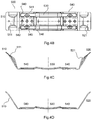
- Fig. 4A to 4D show different views of an outer bracket according to an aspect of the invention.
- the outer bracket 500 is used for water heaters with a round housing which do not have the outer casing 110 as shown in Fig 1 .
- the outer bracket 500 is then mounted to the housing 120.
- the outer bracket 500 comprises a first and second end 510, 520, a middle portion 530 and two mounting portions 540 each between the middle portion 530 and the first and second end 510, 520.
- the first and second end 510, 520 are angled with respect to the middle portion 530 and the mounting portions 540 such that the outer bracket can be attached to a round housing of a water heater.
- the first and second end 510, 520 each comprise an indentation 511, 521.
- the middle portion 530 can be adapted to the outer contour of the water heater.
- Each mounting portion 540 comprises preferably five holes with a hole 543 in the middle. The other four holes are arranged radially as seen from the hole 543.
- the first and fifth hole 541, 545 can be used for a vertical arrangement of the water heater.
- the first and fourth hole 541, 544 can be used for a horizontal mounting of the water heater.
- Fig. 5A to 5D show different views of a hook according to an aspect of the invention.
- the hook 400 comprises a first and second end 410, 420, wherein the second end 420 is spaced apart from a plain of the first end 410.
- the first end 410 can be attached to an outer casing 110 or an outer bracket 500 of the water heater.
- the hook can be attached to the water heater by a screw via the hole 430.
- the second end 420 is then inserted into a hook mounting portion of the wall mounting bracket 300.
- a nipple 412 can be provided which is extending towards the side of the hook which is attached to the water heater.
- the nipple 412 can be used for fixation and easy assembling.
- the first end comprises reinforcing dies 411 and the second end also comprises reinforcing dies 421. These dies are used to increase the stiffness of the hook.
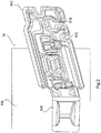
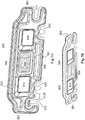
- Fig. 6A to 6G show different views of a wall mounting bracket according to an aspect of the invention.
- Fig. 6A shows a schematic perspective view of the bracket.
- Fig. 6B shows a further perspective view of the bracket.
- Fig. 6C shows a plain view of the bracket.
- Fig. 6D shows a cross section along the plain E - E of the bracket,
- Fig. 6E shows a cross section along the lines A - A.
- Fig. 6F shows a cross section along the line B - B.
- Fig. 6G shows an enlarged detail of D.
- the wall mounting bracket 300 comprises a first and second end 301, 303, a lower end 302 and an upper end 304. At the first and second end 301, 302, a first recess 311 is present.
- second recesses 312 and third recesses 313 are provided.
- the second recesses 312 each comprise a long hole 312a which is substantially aligned with the lower end 302.
- the second recesses 312 comprise a recess 312b leading to the long hole 312a.
- second long holes 314 can each be provided at the four corners 300a - 300d of the bracket.
- the hook mounting portions 310 are embodied as holes which are not connected to the circumference of the bracket 300.
- the bracket 300 may optionally comprise reinforcing dies 320.
- a first reinforcing die 321 may be provided at the lower end 302.
- a further reinforcing die 322 may be provided between the two hook receiving portions 310.
- An additional reinforcing die 323 may be provided at the upper end 304.
- Fig. 7A to 7H show different views of a wall mounting bracket according to a further aspect of the invention.
- the bracket according to the aspect of Fig. 7 comprises a first and second end 301, 303, an upper end 304 and a lower end 302.
- a recess 311 is provided either at the first end 301 or the second end 303.
- the second recess 312 with a long hole 312a is either provided at the first end 301 or at the second end 303.
- third recesses 313 are provided. While in Fig. 6A only one recess is provided at each end, in Fig. 7A , two recesses 313 are provided.
- the bracket 300 comprises two hook receiving portions 310.
- the bracket 300 may comprise several reinforcing dies 321, 322, 323 similar to the reinforcing dies as in Fig. 6A .
- FIG. 8A and 8B show different views of a water heating system according to a further aspect of the invention.
- a water heater 100 with a fixation bracket 200 is depicted.
- a wall mounting bracket 300 (as described in Fig. 6A - 6F ) is attached to the fixation bracket.
- the recesses or holes 314 are used to attach the bracket to the fixation bracket.
- a hook 400 is attached to the fixation bracket 200 and is hooked into the hook receiving portion 310.
- FIG. 9A and 9B different water heating systems are disclosed each with a different wall mounting bracket 300.
- the main feature of the wall mounting bracket is the provision of the hook receiving portion 310.
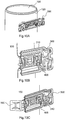
- Fig. 10A to 10C show different views of a water heating system according to an aspect of the invention.
- a first variant of a round water heater is disclosed.
- the water heater comprises an outer casing 110 to which the wall mounting bracket 300 is attached by means of the hooks 400 which engage in the hook receiving portion 310.
- a water heater 100 with an outer bracket 500 is shown.
- the hooks 400 are attached to the bracket 500 and the heater can be hooked by means of the hooks 400 into the hook receiving portion 310.
- Fig. 11A and 11B show a schematic view of a water heating system according to an aspect of the invention.
- the horizontal mounting of the water heater 100 with an outer casing 110 in Fig. 11A and a bracket 500 as seen in Fig. 11B is disclosed.
- Fig. 12A to 12C show a schematic view of a water heating system according to a further aspect of the invention.
- the aspect of the invention is disclosed where the water heater has a square housing.
- the fixation bracket 200 is attached to the housing 120 of the water heater either in a horizontal way as disclosed in Fig. 12A or in a vertical way as disclosed in Fig. 12B .
- several fixation brackets 200 can be provided at the housing 120 of the water heater 100.
Landscapes
- Engineering & Computer Science (AREA)
- General Engineering & Computer Science (AREA)
- Mechanical Engineering (AREA)
- Physics & Mathematics (AREA)
- Thermal Sciences (AREA)
- Chemical & Material Sciences (AREA)
- Combustion & Propulsion (AREA)
- Housings, Intake/Discharge, And Installation Of Fluid Heaters (AREA)
Abstract
Description
- The present invention relates to a water heater system.
- Water heaters like hot water storage tanks are well known and are typically mounted to a wall. As the water heaters can be of considerable weight, the mounting of such a water heater can be difficult for the user.
-
EP 1918 660 B1 discloses a wall mounting bracket for a water heater. The wall mounting bracket can be mounted to the wall and hooks can be attached to the water heater and the water heater can then be hooked to the bracket attached to the wall. The bracket in particular comprises recesses at its top end into which the hooks attached to the water heater can be mounted. - It is an object of the invention to provide a water heater system which can be effectively mounted to a wall.
- This object is achieved by a water heater system according to claim 1.
- The water heater system comprises a water heater, hooks which are attached to the water heater as well as a wall mounting bracket. The wall mounting bracket can be mounted to a wall by means of screws. The wall mounting bracket comprises first holes or recesses for the screws for mounting the wall mounting bracket to the wall. The wall mounting bracket comprises hook mounting portions which are adapted to receive the hooks attached to the water heater. Preferably, the hook mounting portions are closed and are not connected to the circumference of the bracket.
- Instead of providing a hook mounting portion at the circumference of the bracket as shown in
EP 1918 660 B1 , the hook mounting portion according to the invention is arranged inside the wall mounting bracket in such a way that the hook mounting portion is a closed portion. This is advantageous with respect to the distribution of a stress and deformation. The deformation which acts on the mounted bracket when a water heater is hooked into the hook portions is greatest at the top side of the bracket while the deformation on the hook mounting portion is significantly less for a vertical attachment of the water heater to the bracket. In case of a horizontal attachment of the water heater, only the top hook receiving portion will have an increased deformation while the lower second hook does not have significant deformation. - Thus, by changing the position of the hook mounting portion from the circumference of the bracket to the inside of the bracket, the stress distribution and deformation of the bracket can be significantly reduced thus increasing the stability of the entire water heating system when it is mounted to a wall.
- Furthermore, it is much easier to first attach the wall mounting bracket to a wall using screws and only then attach the water heater to the bracket then attaching the entire water heater to a wall. Thus, the mounting of the water heater can be significantly improved.
- Embodiments and advantages of the invention are elucidated in the following figures:
- Fig. 1
- shows a schematic representation of a water heater system according to an aspect of the invention,
- Fig. 2
- shows a schematic representation of a further water heater system according to an aspect of the invention,
- Fig. 3A to 3E
- show different views of a fixation bracket according to an aspect of the invention,
- Fig. 4A to 4D
- show different views of an outer bracket according to an aspect of the invention,
- Fig. 5A to 5D
- show different views of a hook according to an aspect of the invention,
- Fig. 6A to 6G
- show different views of a wall mounting bracket according to an aspect of the invention,
- Fig. 7A to 7H
- show different views of a wall mounting bracket according to a further aspect of the invention,
- Fig. 8A and 8B
- show different views of a water heating system according to a further aspect of the invention,
- Fig. 9A
- shows a schematic view of a water heater system according to an aspect of the invention,
- Fig. 9B
- shows a schematic view of a water heating system according to a further aspect of the invention,
- Fig. 10A to 10C
- show different views of a water heating system according to an aspect of the invention,
- Fig. 11A and 11B
- show a schematic view of a water heating system according to an aspect of the invention, and
- Fig. 12A to 12C
- show a schematic view of a water heating system according to a further aspect of the invention.
-
Fig. 1 shows a schematic representation of a water heater system according to an aspect of the invention. Thewater heating system 10 comprises awater heater 100 which can comprise anouter casing portion 110. Thewater heating system 10 furthermore may comprise afixation bracket 200 which can be attached to theouter casing 110, at least twohooks 400 which can be attached to thefixation bracket 200 or theouter casing 110 as well as awall mounting bracket 300. Thewall mounting bracket 300 can be mounted to a wall and thewater heater 100 with thehooks 400 can be hooked into hook mounting or receivingportions 310 of the bracket. -
Fig. 2 shows a schematic representation of a further water heater system according to an aspect of the invention. Thewater heating system 10 according to the further aspect of the invention comprises anouter bracket 500 instead of an outer casing. Theouter bracket 500 is attached to the housing of thewater heater 100. The hooks can then be attached to the outer bracket and can be hooked into hook mounting (receiving)portions 310 of thewall mounting bracket 300. -
Fig. 3A to 3E show different views of a fixation bracket according to an aspect of the invention.Fig. 3A shows a schematic and perspective view of thefixation bracket 200.Fig. 3B shows a plain view of the fixation bracket.Fig. 3C shows a cross section of the fixation bracket andFig. 3D shows an enlarged portion E of the bracket.Fig. 3E shows a cross section along the lines D - D. Thefixation bracket 200 is substantially rectangular with rounded edges and is substantially flat. Thefixation bracket 200 comprises a number of holes 221 - 226 in particular along a middle line of thebracket 200. Additionally, further holes 231 - 236 are provided which are not aligned with the holes 221 - 226. The holes 21 - 26 can be used to mount the bracket to different water heaters. Theholes -
Fig. 4A to 4D show different views of an outer bracket according to an aspect of the invention. Theouter bracket 500 is used for water heaters with a round housing which do not have theouter casing 110 as shown inFig 1 . Theouter bracket 500 is then mounted to thehousing 120. Theouter bracket 500 comprises a first andsecond end middle portion 530 and two mountingportions 540 each between themiddle portion 530 and the first andsecond end second end middle portion 530 and the mountingportions 540 such that the outer bracket can be attached to a round housing of a water heater. The first andsecond end indentation middle portion 530 can be adapted to the outer contour of the water heater. Each mountingportion 540 comprises preferably five holes with ahole 543 in the middle. The other four holes are arranged radially as seen from thehole 543. The first andfifth hole fourth hole -
Fig. 5A to 5D show different views of a hook according to an aspect of the invention. Thehook 400 comprises a first andsecond end second end 420 is spaced apart from a plain of thefirst end 410. Thefirst end 410 can be attached to anouter casing 110 or anouter bracket 500 of the water heater. The hook can be attached to the water heater by a screw via thehole 430. Thesecond end 420 is then inserted into a hook mounting portion of thewall mounting bracket 300. At thefirst end 410 of thehook 400, anipple 412 can be provided which is extending towards the side of the hook which is attached to the water heater. Thenipple 412 can be used for fixation and easy assembling. The first end comprises reinforcing dies 411 and the second end also comprises reinforcing dies 421. These dies are used to increase the stiffness of the hook. -
Fig. 6A to 6G show different views of a wall mounting bracket according to an aspect of the invention.Fig. 6A shows a schematic perspective view of the bracket.Fig. 6B shows a further perspective view of the bracket.Fig. 6C shows a plain view of the bracket.Fig. 6D shows a cross section along the plain E - E of the bracket,Fig. 6E shows a cross section along the lines A - A.Fig. 6F shows a cross section along the line B - B.Fig. 6G shows an enlarged detail of D. Thewall mounting bracket 300 comprises a first andsecond end lower end 302 and anupper end 304. At the first andsecond end first recess 311 is present. At thelower end 302,second recesses 312 andthird recesses 313 are provided. The second recesses 312 each comprise along hole 312a which is substantially aligned with thelower end 302. Furthermore, thesecond recesses 312 comprise arecess 312b leading to thelong hole 312a. Furthermore, optionally secondlong holes 314 can each be provided at the fourcorners 300a - 300d of the bracket. Thehook mounting portions 310 are embodied as holes which are not connected to the circumference of thebracket 300. - The
bracket 300 may optionally comprise reinforcing dies 320. A first reinforcingdie 321 may be provided at thelower end 302. A further reinforcing die 322 may be provided between the twohook receiving portions 310. An additional reinforcing die 323 may be provided at theupper end 304. -
Fig. 7A to 7H show different views of a wall mounting bracket according to a further aspect of the invention. The bracket according to the aspect ofFig. 7 comprises a first andsecond end upper end 304 and alower end 302. Arecess 311 is provided either at thefirst end 301 or thesecond end 303. Thesecond recess 312 with along hole 312a is either provided at thefirst end 301 or at thesecond end 303. At thelower end 302,third recesses 313 are provided. While inFig. 6A only one recess is provided at each end, inFig. 7A , tworecesses 313 are provided. Furthermore, thebracket 300 comprises twohook receiving portions 310. Furthermore, thebracket 300 may comprise several reinforcing dies 321, 322, 323 similar to the reinforcing dies as inFig. 6A . -
Fig. 8A and 8B show different views of a water heating system according to a further aspect of the invention. Awater heater 100 with afixation bracket 200 is depicted. A wall mounting bracket 300 (as described inFig. 6A - 6F ) is attached to the fixation bracket. In particular, the recesses orholes 314 are used to attach the bracket to the fixation bracket. Ahook 400 is attached to thefixation bracket 200 and is hooked into thehook receiving portion 310. - In
Fig. 9A and 9B , different water heating systems are disclosed each with a differentwall mounting bracket 300. However, the main feature of the wall mounting bracket is the provision of thehook receiving portion 310. -
Fig. 10A to 10C show different views of a water heating system according to an aspect of the invention. InFig. 10A and 10B , a first variant of a round water heater is disclosed. The water heater comprises anouter casing 110 to which thewall mounting bracket 300 is attached by means of thehooks 400 which engage in thehook receiving portion 310. InFig. 10C , awater heater 100 with anouter bracket 500 is shown. Thehooks 400 are attached to thebracket 500 and the heater can be hooked by means of thehooks 400 into thehook receiving portion 310. -
Fig. 11A and 11B show a schematic view of a water heating system according to an aspect of the invention. InFig. 11A and 11B , the horizontal mounting of thewater heater 100 with anouter casing 110 inFig. 11A and abracket 500 as seen inFig. 11B is disclosed. -
Fig. 12A to 12C show a schematic view of a water heating system according to a further aspect of the invention. InFig. 12A to 12C , the aspect of the invention is disclosed where the water heater has a square housing. Thefixation bracket 200 is attached to thehousing 120 of the water heater either in a horizontal way as disclosed inFig. 12A or in a vertical way as disclosed inFig. 12B . As seen inFig. 12C ,several fixation brackets 200 can be provided at thehousing 120 of thewater heater 100.
Claims (5)
- Water heater system, comprising
a water heater (100), and
a wall mounting bracket (300) having at least two hook receiving portions (310),
at least two hooks (400) coupled to the water heater (100) configured to engage into the at least two hook receiving portions (310) of the bracket (300),
wherein the hook receiving portions (310) are arranged in the wall mounting bracket (300) without a connection to a circumference of the wall mounting bracket (300). - Water heater system according to claim 1, wherein the wall mounting bracket (300) comprises
at least two long holes (312a) which are each connected to the circumference of the bracket (300),
wherein the at least two long holes (312a) are configured to receive screws for mounting the wall mounting bracket (300) to a wall. - Water heater system according to claim 1 or 2, further comprising
a fixation bracket (200) coupled to a housing (120) of the water heater (100),
wherein the fixation bracket (200) comprises at least two first through holes (121 - 126) arranged substantially in the middle of the fixation bracket (200), which are configured such that the fixation bracket (200) is mounted to the water heater (100), and at least two second holes (231 - 236) configured for fixing the hooks to the fixation bracket to allow a vertical or horizontal mounting of the water heater. - Water heater system according to anyone of the claims 1 to 3, further comprising
an outer bracket (500) configured to be attached to a round housing (120) of the water heater,
wherein the outer bracket (500) comprises a first and second end (510, 520), a middle portion (530) and two mounting portions (540), each between the middle portion (530) and the first and second end (510, 520), - Water heater system according to anyone of the claims 1 to 4,
wherein the wall mounting bracket (300) comprises at least one reinforcing die (321, 323).
Priority Applications (1)
| Application Number | Priority Date | Filing Date | Title |
|---|---|---|---|
| EP18207691.9A EP3657092B1 (en) | 2018-11-22 | 2018-11-22 | Water heater system |
Applications Claiming Priority (1)
| Application Number | Priority Date | Filing Date | Title |
|---|---|---|---|
| EP18207691.9A EP3657092B1 (en) | 2018-11-22 | 2018-11-22 | Water heater system |
Publications (2)
| Publication Number | Publication Date |
|---|---|
| EP3657092A1 true EP3657092A1 (en) | 2020-05-27 |
| EP3657092B1 EP3657092B1 (en) | 2023-06-07 |
Family
ID=64453312
Family Applications (1)
| Application Number | Title | Priority Date | Filing Date |
|---|---|---|---|
| EP18207691.9A Active EP3657092B1 (en) | 2018-11-22 | 2018-11-22 | Water heater system |
Country Status (1)
| Country | Link |
|---|---|
| EP (1) | EP3657092B1 (en) |
Citations (8)
| Publication number | Priority date | Publication date | Assignee | Title |
|---|---|---|---|---|
| FR2471348A1 (en) * | 1979-12-12 | 1981-06-19 | Yaich Victor | Hoist bracket for lifting domestic boiler - has eyelets for lifting rope and slots for mounting bolts |
| US4848714A (en) * | 1987-10-09 | 1989-07-18 | Ziaylek Theodore Jun | Mounting plate with rollers |
| US5487518A (en) * | 1994-02-03 | 1996-01-30 | Mccraney; William E. | Water heater restraint |
| AT410367B (en) * | 2001-03-23 | 2003-04-25 | Vaillant Gmbh | Device for retention of equipment module on carrier e.g. for continuous flow heaters, uses formed hooks that locate in slots and spring elements with grooved surface which engage matching surface |
| EP1918660A2 (en) * | 2006-10-26 | 2008-05-07 | STIEBEL ELTRON GmbH & Co. KG | Wall bracket for a water heater |
| EP2330361A2 (en) * | 2009-11-24 | 2011-06-08 | BSH Bosch und Siemens Hausgeräte GmbH | Heater with fixing device |
| FR2979978A1 (en) * | 2011-09-08 | 2013-03-15 | Atlantic Industrie Sas | Supporting device for fixing electric water-heater on e.g. wall, of e.g. office, has reinforcements for assembly of clamp fixed to wall to mount clamp according to position chosen from distances between centers defined by reinforcements |
| CN106247108A (en) * | 2016-09-23 | 2016-12-21 | 宁波方太厨具有限公司 | A mounting frame for wall-mounted home appliances and a range hood matched with the mounting frame |
-
2018
- 2018-11-22 EP EP18207691.9A patent/EP3657092B1/en active Active
Patent Citations (9)
| Publication number | Priority date | Publication date | Assignee | Title |
|---|---|---|---|---|
| FR2471348A1 (en) * | 1979-12-12 | 1981-06-19 | Yaich Victor | Hoist bracket for lifting domestic boiler - has eyelets for lifting rope and slots for mounting bolts |
| US4848714A (en) * | 1987-10-09 | 1989-07-18 | Ziaylek Theodore Jun | Mounting plate with rollers |
| US5487518A (en) * | 1994-02-03 | 1996-01-30 | Mccraney; William E. | Water heater restraint |
| AT410367B (en) * | 2001-03-23 | 2003-04-25 | Vaillant Gmbh | Device for retention of equipment module on carrier e.g. for continuous flow heaters, uses formed hooks that locate in slots and spring elements with grooved surface which engage matching surface |
| EP1918660A2 (en) * | 2006-10-26 | 2008-05-07 | STIEBEL ELTRON GmbH & Co. KG | Wall bracket for a water heater |
| EP1918660B1 (en) | 2006-10-26 | 2015-08-05 | STIEBEL ELTRON GmbH & Co. KG | Wall bracket for a water heater |
| EP2330361A2 (en) * | 2009-11-24 | 2011-06-08 | BSH Bosch und Siemens Hausgeräte GmbH | Heater with fixing device |
| FR2979978A1 (en) * | 2011-09-08 | 2013-03-15 | Atlantic Industrie Sas | Supporting device for fixing electric water-heater on e.g. wall, of e.g. office, has reinforcements for assembly of clamp fixed to wall to mount clamp according to position chosen from distances between centers defined by reinforcements |
| CN106247108A (en) * | 2016-09-23 | 2016-12-21 | 宁波方太厨具有限公司 | A mounting frame for wall-mounted home appliances and a range hood matched with the mounting frame |
Also Published As
| Publication number | Publication date |
|---|---|
| EP3657092B1 (en) | 2023-06-07 |
Similar Documents
| Publication | Publication Date | Title |
|---|---|---|
| EP2366838B1 (en) | Frame for fixing sanitary fixtures to a wall | |
| WO2000027267A1 (en) | Shower enclosure system | |
| HK55892A (en) | Connecting piece to connect a drawer rail | |
| EP4081069B1 (en) | Storage system | |
| US6913235B2 (en) | Symmetrically designed snap-on shelf | |
| EP3657092B1 (en) | Water heater system | |
| FR2979978A1 (en) | Supporting device for fixing electric water-heater on e.g. wall, of e.g. office, has reinforcements for assembly of clamp fixed to wall to mount clamp according to position chosen from distances between centers defined by reinforcements | |
| EP0583611A1 (en) | Metallic enclosure with easy installation | |
| CN213243183U (en) | Wall hanging device for fixing power distribution cabinet | |
| CN208851153U (en) | A kind of hook | |
| CN209159833U (en) | A kind of erection support of petroleum well servicing rig driver's cabin | |
| CN206092606U (en) | Structure imbeds behind built -in fitting | |
| US3228644A (en) | Radiator hanger | |
| US3345022A (en) | Bus duct hanger | |
| CN220470388U (en) | Connecting piece | |
| JP5010449B2 (en) | Building basic structure | |
| CN212338837U (en) | Installation base and terminal equipment | |
| CN211049196U (en) | Force bearing pipe convenient to lock and commodity shelf using same | |
| CN213775936U (en) | Split type wall-hung frame | |
| CN220080446U (en) | Adjustable glass curtain wall connecting assembly | |
| CN222091132U (en) | Multifunctional clothes hanger for storage cabinet and storage cabinet | |
| EP1800590A1 (en) | Support for dishwasher basket guides | |
| JP4278571B2 (en) | Fixed structure of hot water storage type electric water heater | |
| CN214148012U (en) | Embedded gas furnace | |
| CN213145013U (en) | Self-locking bolt for thin-wall component |
Legal Events
| Date | Code | Title | Description |
|---|---|---|---|
| PUAI | Public reference made under article 153(3) epc to a published international application that has entered the european phase |
Free format text: ORIGINAL CODE: 0009012 |
|
| STAA | Information on the status of an ep patent application or granted ep patent |
Free format text: STATUS: THE APPLICATION HAS BEEN PUBLISHED |
|
| AK | Designated contracting states |
Kind code of ref document: A1 Designated state(s): AL AT BE BG CH CY CZ DE DK EE ES FI FR GB GR HR HU IE IS IT LI LT LU LV MC MK MT NL NO PL PT RO RS SE SI SK SM TR |
|
| AX | Request for extension of the european patent |
Extension state: BA ME |
|
| STAA | Information on the status of an ep patent application or granted ep patent |
Free format text: STATUS: REQUEST FOR EXAMINATION WAS MADE |
|
| 17P | Request for examination filed |
Effective date: 20201127 |
|
| RBV | Designated contracting states (corrected) |
Designated state(s): AL AT BE BG CH CY CZ DE DK EE ES FI FR GB GR HR HU IE IS IT LI LT LU LV MC MK MT NL NO PL PT RO RS SE SI SK SM TR |
|
| GRAP | Despatch of communication of intention to grant a patent |
Free format text: ORIGINAL CODE: EPIDOSNIGR1 |
|
| STAA | Information on the status of an ep patent application or granted ep patent |
Free format text: STATUS: GRANT OF PATENT IS INTENDED |
|
| INTG | Intention to grant announced |
Effective date: 20230104 |
|
| GRAS | Grant fee paid |
Free format text: ORIGINAL CODE: EPIDOSNIGR3 |
|
| GRAA | (expected) grant |
Free format text: ORIGINAL CODE: 0009210 |
|
| STAA | Information on the status of an ep patent application or granted ep patent |
Free format text: STATUS: THE PATENT HAS BEEN GRANTED |
|
| AK | Designated contracting states |
Kind code of ref document: B1 Designated state(s): AL AT BE BG CH CY CZ DE DK EE ES FI FR GB GR HR HU IE IS IT LI LT LU LV MC MK MT NL NO PL PT RO RS SE SI SK SM TR |
|
| REG | Reference to a national code |
Ref country code: GB Ref legal event code: FG4D |
|
| REG | Reference to a national code |
Ref country code: CH Ref legal event code: EP Ref country code: AT Ref legal event code: REF Ref document number: 1576193 Country of ref document: AT Kind code of ref document: T Effective date: 20230615 |
|
| REG | Reference to a national code |
Ref country code: DE Ref legal event code: R096 Ref document number: 602018050795 Country of ref document: DE |
|
| P01 | Opt-out of the competence of the unified patent court (upc) registered |
Effective date: 20230519 |
|
| REG | Reference to a national code |
Ref country code: LT Ref legal event code: MG9D |
|
| REG | Reference to a national code |
Ref country code: NL Ref legal event code: MP Effective date: 20230607 |
|
| PG25 | Lapsed in a contracting state [announced via postgrant information from national office to epo] |
Ref country code: SE Free format text: LAPSE BECAUSE OF FAILURE TO SUBMIT A TRANSLATION OF THE DESCRIPTION OR TO PAY THE FEE WITHIN THE PRESCRIBED TIME-LIMIT Effective date: 20230607 Ref country code: NO Free format text: LAPSE BECAUSE OF FAILURE TO SUBMIT A TRANSLATION OF THE DESCRIPTION OR TO PAY THE FEE WITHIN THE PRESCRIBED TIME-LIMIT Effective date: 20230907 Ref country code: ES Free format text: LAPSE BECAUSE OF FAILURE TO SUBMIT A TRANSLATION OF THE DESCRIPTION OR TO PAY THE FEE WITHIN THE PRESCRIBED TIME-LIMIT Effective date: 20230607 |
|
| PG25 | Lapsed in a contracting state [announced via postgrant information from national office to epo] |
Ref country code: RS Free format text: LAPSE BECAUSE OF FAILURE TO SUBMIT A TRANSLATION OF THE DESCRIPTION OR TO PAY THE FEE WITHIN THE PRESCRIBED TIME-LIMIT Effective date: 20230607 Ref country code: NL Free format text: LAPSE BECAUSE OF FAILURE TO SUBMIT A TRANSLATION OF THE DESCRIPTION OR TO PAY THE FEE WITHIN THE PRESCRIBED TIME-LIMIT Effective date: 20230607 Ref country code: LV Free format text: LAPSE BECAUSE OF FAILURE TO SUBMIT A TRANSLATION OF THE DESCRIPTION OR TO PAY THE FEE WITHIN THE PRESCRIBED TIME-LIMIT Effective date: 20230607 Ref country code: LT Free format text: LAPSE BECAUSE OF FAILURE TO SUBMIT A TRANSLATION OF THE DESCRIPTION OR TO PAY THE FEE WITHIN THE PRESCRIBED TIME-LIMIT Effective date: 20230607 Ref country code: HR Free format text: LAPSE BECAUSE OF FAILURE TO SUBMIT A TRANSLATION OF THE DESCRIPTION OR TO PAY THE FEE WITHIN THE PRESCRIBED TIME-LIMIT Effective date: 20230607 Ref country code: GR Free format text: LAPSE BECAUSE OF FAILURE TO SUBMIT A TRANSLATION OF THE DESCRIPTION OR TO PAY THE FEE WITHIN THE PRESCRIBED TIME-LIMIT Effective date: 20230908 |
|
| PG25 | Lapsed in a contracting state [announced via postgrant information from national office to epo] |
Ref country code: FI Free format text: LAPSE BECAUSE OF FAILURE TO SUBMIT A TRANSLATION OF THE DESCRIPTION OR TO PAY THE FEE WITHIN THE PRESCRIBED TIME-LIMIT Effective date: 20230607 |
|
| PG25 | Lapsed in a contracting state [announced via postgrant information from national office to epo] |
Ref country code: SK Free format text: LAPSE BECAUSE OF FAILURE TO SUBMIT A TRANSLATION OF THE DESCRIPTION OR TO PAY THE FEE WITHIN THE PRESCRIBED TIME-LIMIT Effective date: 20230607 |
|
| PG25 | Lapsed in a contracting state [announced via postgrant information from national office to epo] |
Ref country code: IS Free format text: LAPSE BECAUSE OF FAILURE TO SUBMIT A TRANSLATION OF THE DESCRIPTION OR TO PAY THE FEE WITHIN THE PRESCRIBED TIME-LIMIT Effective date: 20231007 |
|
| PG25 | Lapsed in a contracting state [announced via postgrant information from national office to epo] |
Ref country code: SM Free format text: LAPSE BECAUSE OF FAILURE TO SUBMIT A TRANSLATION OF THE DESCRIPTION OR TO PAY THE FEE WITHIN THE PRESCRIBED TIME-LIMIT Effective date: 20230607 Ref country code: SK Free format text: LAPSE BECAUSE OF FAILURE TO SUBMIT A TRANSLATION OF THE DESCRIPTION OR TO PAY THE FEE WITHIN THE PRESCRIBED TIME-LIMIT Effective date: 20230607 Ref country code: RO Free format text: LAPSE BECAUSE OF FAILURE TO SUBMIT A TRANSLATION OF THE DESCRIPTION OR TO PAY THE FEE WITHIN THE PRESCRIBED TIME-LIMIT Effective date: 20230607 Ref country code: PT Free format text: LAPSE BECAUSE OF FAILURE TO SUBMIT A TRANSLATION OF THE DESCRIPTION OR TO PAY THE FEE WITHIN THE PRESCRIBED TIME-LIMIT Effective date: 20231009 Ref country code: IS Free format text: LAPSE BECAUSE OF FAILURE TO SUBMIT A TRANSLATION OF THE DESCRIPTION OR TO PAY THE FEE WITHIN THE PRESCRIBED TIME-LIMIT Effective date: 20231007 Ref country code: EE Free format text: LAPSE BECAUSE OF FAILURE TO SUBMIT A TRANSLATION OF THE DESCRIPTION OR TO PAY THE FEE WITHIN THE PRESCRIBED TIME-LIMIT Effective date: 20230607 Ref country code: CZ Free format text: LAPSE BECAUSE OF FAILURE TO SUBMIT A TRANSLATION OF THE DESCRIPTION OR TO PAY THE FEE WITHIN THE PRESCRIBED TIME-LIMIT Effective date: 20230607 |
|
| REG | Reference to a national code |
Ref country code: AT Ref legal event code: UEP Ref document number: 1576193 Country of ref document: AT Kind code of ref document: T Effective date: 20230607 |
|
| PG25 | Lapsed in a contracting state [announced via postgrant information from national office to epo] |
Ref country code: PL Free format text: LAPSE BECAUSE OF FAILURE TO SUBMIT A TRANSLATION OF THE DESCRIPTION OR TO PAY THE FEE WITHIN THE PRESCRIBED TIME-LIMIT Effective date: 20230607 |
|
| REG | Reference to a national code |
Ref country code: DE Ref legal event code: R097 Ref document number: 602018050795 Country of ref document: DE |
|
| PLBE | No opposition filed within time limit |
Free format text: ORIGINAL CODE: 0009261 |
|
| STAA | Information on the status of an ep patent application or granted ep patent |
Free format text: STATUS: NO OPPOSITION FILED WITHIN TIME LIMIT |
|
| PG25 | Lapsed in a contracting state [announced via postgrant information from national office to epo] |
Ref country code: DK Free format text: LAPSE BECAUSE OF FAILURE TO SUBMIT A TRANSLATION OF THE DESCRIPTION OR TO PAY THE FEE WITHIN THE PRESCRIBED TIME-LIMIT Effective date: 20230607 |
|
| PG25 | Lapsed in a contracting state [announced via postgrant information from national office to epo] |
Ref country code: SI Free format text: LAPSE BECAUSE OF FAILURE TO SUBMIT A TRANSLATION OF THE DESCRIPTION OR TO PAY THE FEE WITHIN THE PRESCRIBED TIME-LIMIT Effective date: 20230607 |
|
| 26N | No opposition filed |
Effective date: 20240308 |
|
| PG25 | Lapsed in a contracting state [announced via postgrant information from national office to epo] |
Ref country code: SI Free format text: LAPSE BECAUSE OF FAILURE TO SUBMIT A TRANSLATION OF THE DESCRIPTION OR TO PAY THE FEE WITHIN THE PRESCRIBED TIME-LIMIT Effective date: 20230607 Ref country code: IT Free format text: LAPSE BECAUSE OF FAILURE TO SUBMIT A TRANSLATION OF THE DESCRIPTION OR TO PAY THE FEE WITHIN THE PRESCRIBED TIME-LIMIT Effective date: 20230607 |
|
| REG | Reference to a national code |
Ref country code: CH Ref legal event code: PL |
|
| PG25 | Lapsed in a contracting state [announced via postgrant information from national office to epo] |
Ref country code: MC Free format text: LAPSE BECAUSE OF FAILURE TO SUBMIT A TRANSLATION OF THE DESCRIPTION OR TO PAY THE FEE WITHIN THE PRESCRIBED TIME-LIMIT Effective date: 20230607 |
|
| PG25 | Lapsed in a contracting state [announced via postgrant information from national office to epo] |
Ref country code: LU Free format text: LAPSE BECAUSE OF NON-PAYMENT OF DUE FEES Effective date: 20231122 |
|
| PG25 | Lapsed in a contracting state [announced via postgrant information from national office to epo] |
Ref country code: CH Free format text: LAPSE BECAUSE OF NON-PAYMENT OF DUE FEES Effective date: 20231130 |
|
| GBPC | Gb: european patent ceased through non-payment of renewal fee |
Effective date: 20231122 |
|
| PG25 | Lapsed in a contracting state [announced via postgrant information from national office to epo] |
Ref country code: MC Free format text: LAPSE BECAUSE OF FAILURE TO SUBMIT A TRANSLATION OF THE DESCRIPTION OR TO PAY THE FEE WITHIN THE PRESCRIBED TIME-LIMIT Effective date: 20230607 Ref country code: LU Free format text: LAPSE BECAUSE OF NON-PAYMENT OF DUE FEES Effective date: 20231122 Ref country code: CH Free format text: LAPSE BECAUSE OF NON-PAYMENT OF DUE FEES Effective date: 20231130 |
|
| REG | Reference to a national code |
Ref country code: BE Ref legal event code: MM Effective date: 20231130 |
|
| REG | Reference to a national code |
Ref country code: IE Ref legal event code: MM4A |
|
| PG25 | Lapsed in a contracting state [announced via postgrant information from national office to epo] |
Ref country code: IE Free format text: LAPSE BECAUSE OF NON-PAYMENT OF DUE FEES Effective date: 20231122 |
|
| PG25 | Lapsed in a contracting state [announced via postgrant information from national office to epo] |
Ref country code: GB Free format text: LAPSE BECAUSE OF NON-PAYMENT OF DUE FEES Effective date: 20231122 |
|
| PG25 | Lapsed in a contracting state [announced via postgrant information from national office to epo] |
Ref country code: BE Free format text: LAPSE BECAUSE OF NON-PAYMENT OF DUE FEES Effective date: 20231130 |
|
| PG25 | Lapsed in a contracting state [announced via postgrant information from national office to epo] |
Ref country code: FR Free format text: LAPSE BECAUSE OF NON-PAYMENT OF DUE FEES Effective date: 20231130 |
|
| PG25 | Lapsed in a contracting state [announced via postgrant information from national office to epo] |
Ref country code: IE Free format text: LAPSE BECAUSE OF NON-PAYMENT OF DUE FEES Effective date: 20231122 Ref country code: GB Free format text: LAPSE BECAUSE OF NON-PAYMENT OF DUE FEES Effective date: 20231122 Ref country code: FR Free format text: LAPSE BECAUSE OF NON-PAYMENT OF DUE FEES Effective date: 20231130 Ref country code: BE Free format text: LAPSE BECAUSE OF NON-PAYMENT OF DUE FEES Effective date: 20231130 |
|
| PG25 | Lapsed in a contracting state [announced via postgrant information from national office to epo] |
Ref country code: BG Free format text: LAPSE BECAUSE OF FAILURE TO SUBMIT A TRANSLATION OF THE DESCRIPTION OR TO PAY THE FEE WITHIN THE PRESCRIBED TIME-LIMIT Effective date: 20230607 |
|
| PG25 | Lapsed in a contracting state [announced via postgrant information from national office to epo] |
Ref country code: BG Free format text: LAPSE BECAUSE OF FAILURE TO SUBMIT A TRANSLATION OF THE DESCRIPTION OR TO PAY THE FEE WITHIN THE PRESCRIBED TIME-LIMIT Effective date: 20230607 |
|
| PG25 | Lapsed in a contracting state [announced via postgrant information from national office to epo] |
Ref country code: CY Free format text: LAPSE BECAUSE OF FAILURE TO SUBMIT A TRANSLATION OF THE DESCRIPTION OR TO PAY THE FEE WITHIN THE PRESCRIBED TIME-LIMIT; INVALID AB INITIO Effective date: 20181122 |
|
| PG25 | Lapsed in a contracting state [announced via postgrant information from national office to epo] |
Ref country code: HU Free format text: LAPSE BECAUSE OF FAILURE TO SUBMIT A TRANSLATION OF THE DESCRIPTION OR TO PAY THE FEE WITHIN THE PRESCRIBED TIME-LIMIT; INVALID AB INITIO Effective date: 20181122 |
|
| PG25 | Lapsed in a contracting state [announced via postgrant information from national office to epo] |
Ref country code: TR Free format text: LAPSE BECAUSE OF FAILURE TO SUBMIT A TRANSLATION OF THE DESCRIPTION OR TO PAY THE FEE WITHIN THE PRESCRIBED TIME-LIMIT Effective date: 20230607 |
|
| PGFP | Annual fee paid to national office [announced via postgrant information from national office to epo] |
Ref country code: DE Payment date: 20251119 Year of fee payment: 8 |
|
| PGFP | Annual fee paid to national office [announced via postgrant information from national office to epo] |
Ref country code: AT Payment date: 20251120 Year of fee payment: 8 |