EP3657013A1 - System of rotor, transmission and collection elements that optimises a vertical-axis wind turbine - Google Patents
System of rotor, transmission and collection elements that optimises a vertical-axis wind turbine Download PDFInfo
- Publication number
- EP3657013A1 EP3657013A1 EP18836162.0A EP18836162A EP3657013A1 EP 3657013 A1 EP3657013 A1 EP 3657013A1 EP 18836162 A EP18836162 A EP 18836162A EP 3657013 A1 EP3657013 A1 EP 3657013A1
- Authority
- EP
- European Patent Office
- Prior art keywords
- rotor
- transmission
- vertical axis
- optimises
- wind turbine
- Prior art date
- Legal status (The legal status is an assumption and is not a legal conclusion. Google has not performed a legal analysis and makes no representation as to the accuracy of the status listed.)
- Withdrawn
Links
- 230000005540 biological transmission Effects 0.000 title claims abstract description 22
- 230000007246 mechanism Effects 0.000 claims abstract description 11
- 239000002184 metal Substances 0.000 claims abstract description 9
- 239000004020 conductor Substances 0.000 claims description 5
- 229910000746 Structural steel Inorganic materials 0.000 claims description 2
- 238000004873 anchoring Methods 0.000 claims description 2
- 239000003351 stiffener Substances 0.000 claims description 2
- 239000002023 wood Substances 0.000 claims description 2
- 238000004519 manufacturing process Methods 0.000 description 3
- 230000005611 electricity Effects 0.000 description 2
- 230000033001 locomotion Effects 0.000 description 2
- 239000000470 constituent Substances 0.000 description 1
- 238000013461 design Methods 0.000 description 1
- 238000011161 development Methods 0.000 description 1
- 238000005516 engineering process Methods 0.000 description 1
- 238000003780 insertion Methods 0.000 description 1
- 230000037431 insertion Effects 0.000 description 1
- 238000009434 installation Methods 0.000 description 1
- 230000010355 oscillation Effects 0.000 description 1
- 238000011160 research Methods 0.000 description 1
- 230000005570 vertical transmission Effects 0.000 description 1
Images



Classifications
-
- F—MECHANICAL ENGINEERING; LIGHTING; HEATING; WEAPONS; BLASTING
- F03—MACHINES OR ENGINES FOR LIQUIDS; WIND, SPRING, OR WEIGHT MOTORS; PRODUCING MECHANICAL POWER OR A REACTIVE PROPULSIVE THRUST, NOT OTHERWISE PROVIDED FOR
- F03D—WIND MOTORS
- F03D3/00—Wind motors with rotation axis substantially perpendicular to the air flow entering the rotor
- F03D3/005—Wind motors with rotation axis substantially perpendicular to the air flow entering the rotor the axis being vertical
-
- F—MECHANICAL ENGINEERING; LIGHTING; HEATING; WEAPONS; BLASTING
- F03—MACHINES OR ENGINES FOR LIQUIDS; WIND, SPRING, OR WEIGHT MOTORS; PRODUCING MECHANICAL POWER OR A REACTIVE PROPULSIVE THRUST, NOT OTHERWISE PROVIDED FOR
- F03D—WIND MOTORS
- F03D15/00—Transmission of mechanical power
-
- F—MECHANICAL ENGINEERING; LIGHTING; HEATING; WEAPONS; BLASTING
- F03—MACHINES OR ENGINES FOR LIQUIDS; WIND, SPRING, OR WEIGHT MOTORS; PRODUCING MECHANICAL POWER OR A REACTIVE PROPULSIVE THRUST, NOT OTHERWISE PROVIDED FOR
- F03D—WIND MOTORS
- F03D3/00—Wind motors with rotation axis substantially perpendicular to the air flow entering the rotor
-
- F—MECHANICAL ENGINEERING; LIGHTING; HEATING; WEAPONS; BLASTING
- F03—MACHINES OR ENGINES FOR LIQUIDS; WIND, SPRING, OR WEIGHT MOTORS; PRODUCING MECHANICAL POWER OR A REACTIVE PROPULSIVE THRUST, NOT OTHERWISE PROVIDED FOR
- F03D—WIND MOTORS
- F03D3/00—Wind motors with rotation axis substantially perpendicular to the air flow entering the rotor
- F03D3/06—Rotors
-
- F—MECHANICAL ENGINEERING; LIGHTING; HEATING; WEAPONS; BLASTING
- F03—MACHINES OR ENGINES FOR LIQUIDS; WIND, SPRING, OR WEIGHT MOTORS; PRODUCING MECHANICAL POWER OR A REACTIVE PROPULSIVE THRUST, NOT OTHERWISE PROVIDED FOR
- F03D—WIND MOTORS
- F03D7/00—Controlling wind motors
- F03D7/06—Controlling wind motors the wind motors having rotation axis substantially perpendicular to the air flow entering the rotor
-
- F—MECHANICAL ENGINEERING; LIGHTING; HEATING; WEAPONS; BLASTING
- F03—MACHINES OR ENGINES FOR LIQUIDS; WIND, SPRING, OR WEIGHT MOTORS; PRODUCING MECHANICAL POWER OR A REACTIVE PROPULSIVE THRUST, NOT OTHERWISE PROVIDED FOR
- F03D—WIND MOTORS
- F03D9/00—Adaptations of wind motors for special use; Combinations of wind motors with apparatus driven thereby; Wind motors specially adapted for installation in particular locations
- F03D9/30—Wind motors specially adapted for installation in particular locations
- F03D9/34—Wind motors specially adapted for installation in particular locations on stationary objects or on stationary man-made structures
- F03D9/43—Wind motors specially adapted for installation in particular locations on stationary objects or on stationary man-made structures using infrastructure primarily used for other purposes, e.g. masts for overhead railway power lines
-
- F—MECHANICAL ENGINEERING; LIGHTING; HEATING; WEAPONS; BLASTING
- F03—MACHINES OR ENGINES FOR LIQUIDS; WIND, SPRING, OR WEIGHT MOTORS; PRODUCING MECHANICAL POWER OR A REACTIVE PROPULSIVE THRUST, NOT OTHERWISE PROVIDED FOR
- F03D—WIND MOTORS
- F03D3/00—Wind motors with rotation axis substantially perpendicular to the air flow entering the rotor
- F03D3/06—Rotors
- F03D3/062—Rotors characterised by their construction elements
- F03D3/066—Rotors characterised by their construction elements the wind engaging parts being movable relative to the rotor
- F03D3/067—Cyclic movements
-
- F—MECHANICAL ENGINEERING; LIGHTING; HEATING; WEAPONS; BLASTING
- F05—INDEXING SCHEMES RELATING TO ENGINES OR PUMPS IN VARIOUS SUBCLASSES OF CLASSES F01-F04
- F05B—INDEXING SCHEME RELATING TO WIND, SPRING, WEIGHT, INERTIA OR LIKE MOTORS, TO MACHINES OR ENGINES FOR LIQUIDS COVERED BY SUBCLASSES F03B, F03D AND F03G
- F05B2260/00—Function
- F05B2260/40—Transmission of power
- F05B2260/403—Transmission of power through the shape of the drive components
- F05B2260/4031—Transmission of power through the shape of the drive components as in toothed gearing
- F05B2260/40311—Transmission of power through the shape of the drive components as in toothed gearing of the epicyclic, planetary or differential type
-
- F—MECHANICAL ENGINEERING; LIGHTING; HEATING; WEAPONS; BLASTING
- F05—INDEXING SCHEMES RELATING TO ENGINES OR PUMPS IN VARIOUS SUBCLASSES OF CLASSES F01-F04
- F05B—INDEXING SCHEME RELATING TO WIND, SPRING, WEIGHT, INERTIA OR LIKE MOTORS, TO MACHINES OR ENGINES FOR LIQUIDS COVERED BY SUBCLASSES F03B, F03D AND F03G
- F05B2260/00—Function
- F05B2260/50—Kinematic linkage, i.e. transmission of position
- F05B2260/506—Kinematic linkage, i.e. transmission of position using cams or eccentrics
-
- F—MECHANICAL ENGINEERING; LIGHTING; HEATING; WEAPONS; BLASTING
- F05—INDEXING SCHEMES RELATING TO ENGINES OR PUMPS IN VARIOUS SUBCLASSES OF CLASSES F01-F04
- F05B—INDEXING SCHEME RELATING TO WIND, SPRING, WEIGHT, INERTIA OR LIKE MOTORS, TO MACHINES OR ENGINES FOR LIQUIDS COVERED BY SUBCLASSES F03B, F03D AND F03G
- F05B2260/00—Function
- F05B2260/70—Adjusting of angle of incidence or attack of rotating blades
- F05B2260/79—Bearing, support or actuation arrangements therefor
-
- Y—GENERAL TAGGING OF NEW TECHNOLOGICAL DEVELOPMENTS; GENERAL TAGGING OF CROSS-SECTIONAL TECHNOLOGIES SPANNING OVER SEVERAL SECTIONS OF THE IPC; TECHNICAL SUBJECTS COVERED BY FORMER USPC CROSS-REFERENCE ART COLLECTIONS [XRACs] AND DIGESTS
- Y02—TECHNOLOGIES OR APPLICATIONS FOR MITIGATION OR ADAPTATION AGAINST CLIMATE CHANGE
- Y02B—CLIMATE CHANGE MITIGATION TECHNOLOGIES RELATED TO BUILDINGS, e.g. HOUSING, HOUSE APPLIANCES OR RELATED END-USER APPLICATIONS
- Y02B10/00—Integration of renewable energy sources in buildings
- Y02B10/30—Wind power
-
- Y—GENERAL TAGGING OF NEW TECHNOLOGICAL DEVELOPMENTS; GENERAL TAGGING OF CROSS-SECTIONAL TECHNOLOGIES SPANNING OVER SEVERAL SECTIONS OF THE IPC; TECHNICAL SUBJECTS COVERED BY FORMER USPC CROSS-REFERENCE ART COLLECTIONS [XRACs] AND DIGESTS
- Y02—TECHNOLOGIES OR APPLICATIONS FOR MITIGATION OR ADAPTATION AGAINST CLIMATE CHANGE
- Y02E—REDUCTION OF GREENHOUSE GAS [GHG] EMISSIONS, RELATED TO ENERGY GENERATION, TRANSMISSION OR DISTRIBUTION
- Y02E10/00—Energy generation through renewable energy sources
- Y02E10/70—Wind energy
- Y02E10/728—Onshore wind turbines
-
- Y—GENERAL TAGGING OF NEW TECHNOLOGICAL DEVELOPMENTS; GENERAL TAGGING OF CROSS-SECTIONAL TECHNOLOGIES SPANNING OVER SEVERAL SECTIONS OF THE IPC; TECHNICAL SUBJECTS COVERED BY FORMER USPC CROSS-REFERENCE ART COLLECTIONS [XRACs] AND DIGESTS
- Y02—TECHNOLOGIES OR APPLICATIONS FOR MITIGATION OR ADAPTATION AGAINST CLIMATE CHANGE
- Y02E—REDUCTION OF GREENHOUSE GAS [GHG] EMISSIONS, RELATED TO ENERGY GENERATION, TRANSMISSION OR DISTRIBUTION
- Y02E10/00—Energy generation through renewable energy sources
- Y02E10/70—Wind energy
- Y02E10/74—Wind turbines with rotation axis perpendicular to the wind direction
Definitions
- the present invention relates to a system of rotor, transmission and collection elements that optimises a vertical axis generator, and which has been specially designed to meet the need for clean, efficient and environmentally friendly energy, also considering the impact on the landscape.
- Known vertical axis generators in their different versions are formed by a main tower anchored to the base and provided with corresponding rotors that transmit the movement generated to a vertical axis and the latter to an alternator with insertion of a multiplier box.
- This type of generator has several drawbacks, one of the main ones being the manufacturing thereof since very high diameters are required to be able to generate a tower that can support a high blade surface since otherwise, the production is very low.
- the industrial application of this invention falls within the manufacture of vertical axis wind turbines, and more specifically, systems for optimising windcatching and maximising performance for vertical axis wind turbines.
- Patent P21000171 and utility models 1070905 U and 1070534 U are known and none achieves to correctly solve this problem since they still use tubular structures that prevent the correct positioning of the rotors with the radius they require.
- the system of rotor, transmission and collection elements that optimises a vertical axis wind turbine object of the present invention is formed by a support tower in which this new rotor model is implemented with the components it requires.
- this rotor varies depending on the intended application. Thus, if installed in an electric transport tower, it will be placed in the highest part under the conductor cables and keeping the required safety distances. Otherwise, if it is an urban generator or telephone repeater, it is installed in tubular or more aesthetic structures.
- the rotor is created using electric transport towers as a support axis.
- two parallel crossarms are installed thereon, fastening at their outer ends two parallel rings that serve as a support for the bearings which, fastened to the outer casing, make up the rotor.
- This fixed casing in its inner part comprises a cogwheel that by means of epicyclic gearing will be responsible for transmitting the force of rotation to the centre of the tower, which forms an ideal space to house the transmission that will necessarily be vertical and will run to the multiplier box.
- This rotor moves circularly on "bogies” (wheels) on which the beams that support the blades themselves rest, thus eliminating conventional bearings, simplifying assembly.
- "bogies” are supported on the parallel rings described above, at different (upper and side) angles so as to prevent the rotor from being dislodged from the slide rail.
- These bogies are bearings with a specific configuration since the part forming them accommodates several bearings positioned at different angles thus allowing both a radial and axial support to the rotor.
- the braking system is double. With the slat release, leaving them free to the wind, the pressure is eliminated and by forward-backward motion compensation, the rotation force is cancelled and a brake integral to the transmission axis will allow braking and completely stopping the rotation of the machine.
- the transmission of force is received from the cogwheel integral to the rotor that transfers that force to the epicyclic gearing and the latter to the main axis.
- the generator set In the case of locating the generator set on the ground, it will be composed of several sections connected to each other with swivel heads that correct the typical oscillations of these towers and each section will be self-supported with the corresponding coaxial and radial bearings.
- the blades are materialised on two horizontally parallel beams joined and compacted together by metal boxes inside which the axes and guiding mechanisms are housed, providing support and orientation to the slats. These blades are in a single piece, the rotor axis being the midpoint with which its own weight is balanced without the need for anchors.
- the slats are guided and positioned from their reader mechanism associated with the copying disc and are connected to each other by a toothed strip or axis that forces the sprockets integral to the vertical axis of the slat. This sprocket is located inside the metal boxes and will rotate the slat in the desired direction.
- the electricity generated by the machine is emptied through conventional power lines since the main use of the present invention is to implement this wind turbine in the electric transport network itself.
- a preferred embodiment of the system of rotor, transmission and collection elements that optimises a vertical axis wind turbine object of the present invention, with reference to the numerical references, can be based on a structure of crossarms (1) and beams (2) of structural steel or wood, coupled to an electric transport tower, leaving the rotor (3) with its blades (7) at the convenient distance below the conductor support arms, where, at its centre, the main vertical transmission axis (4) is housed and which will be associated with the multiplier box and its alternator (5). Said main axis (4) also integrally incorporates a brake disc (6) that will allow stopping the machine completely.
- the blades (7) are housed at the crown of the rotor (3), and are constituted by four horizontally parallel beams (2), which run from the outer ring of the rotor (3), and are compacted by metal boxes (8) or angle gears inside which the slat (9) guiding mechanisms are housed and support the slats (9) which run from the anchoring mechanism upwards and downwards leaving this support structure in the middle and rotate on it.
- the slats (9) are guided and positioned from a reader mechanism associated with a copying disc (10) positioned by an orientation sprocket (19) of an electronic mechanism associated with a vane (11), and are connected to each other by a toothed strip (12) or axis that forces sprockets (13) integral to the vertical axis (14) of the slat (9).
- This sprocket (13) is inside the metal boxes (8) and will rotate the slat (9) in the desired direction.
- a platform (1) is elevated, with its anchors and stiffeners, on which a double rail (15) lies, which will serve to move "bogies” (16) or bearings of the rotor (3), which are positioned at different (upper and side) angles so as to prevent the rotor (3) from being dislodged from the double slide rail (15).
- These bogies (16) are bearings with a specific configuration that allows both radial and axial support to the rotor (3).
- the transmission of force is received from the cogwheel (17) integral to the rotor (3) that transfers that force to an epicyclic gearing (18) and the latter to the main axis (4).
- the electricity generated by the machine is emptied through conventional power lines.
- system is installed on a repeater post or other type of tower.
Landscapes
- Engineering & Computer Science (AREA)
- Life Sciences & Earth Sciences (AREA)
- Sustainable Development (AREA)
- Sustainable Energy (AREA)
- Chemical & Material Sciences (AREA)
- Combustion & Propulsion (AREA)
- Mechanical Engineering (AREA)
- General Engineering & Computer Science (AREA)
- Power Engineering (AREA)
- Wind Motors (AREA)
Abstract
Description
- The present invention relates to a system of rotor, transmission and collection elements that optimises a vertical axis generator, and which has been specially designed to meet the need for clean, efficient and environmentally friendly energy, also considering the impact on the landscape.
- The development of several models of vertical axis wind turbines has been attempted taking advantage of new technologies that allow solving the typical complexities of this type of wind turbine.
- Known vertical axis generators in their different versions are formed by a main tower anchored to the base and provided with corresponding rotors that transmit the movement generated to a vertical axis and the latter to an alternator with insertion of a multiplier box.
- This type of generator has several drawbacks, one of the main ones being the manufacturing thereof since very high diameters are required to be able to generate a tower that can support a high blade surface since otherwise, the production is very low.
- Another problem presented by this type of wind turbine is the complex slat guiding system, the power supply thereon and the braking system.
- The advantages of this invention are the following:
- The rotor, transmission and slat guidance described below offers a more versatile wind turbine model with varied applications in the medium power section.
- Its installation and implementation can be performed both in electric transport towers, urban generators, telephone repeaters, etc.
- The slat release proposed by the invention improves the braking system.
- It is a system having great mechanical simplicity, easy assembly and with a very low cost in transportation.
- The industrial application of this invention falls within the manufacture of vertical axis wind turbines, and more specifically, systems for optimising windcatching and maximising performance for vertical axis wind turbines.
- Although no identical invention to that described has been found, the documents found that reflect the state of the art related therewith are explained below.
- Patent
P21000171 1070905 U 1070534 U - Although in the case of
P21000171 - Conclusions: As can be concluded from the research carried out, none of the documents found solves the problems posed as does the proposed invention.
- The system of rotor, transmission and collection elements that optimises a vertical axis wind turbine object of the present invention is formed by a support tower in which this new rotor model is implemented with the components it requires.
- The structure of this rotor varies depending on the intended application. Thus, if installed in an electric transport tower, it will be placed in the highest part under the conductor cables and keeping the required safety distances. Otherwise, if it is an urban generator or telephone repeater, it is installed in tubular or more aesthetic structures.
- The rotor is created using electric transport towers as a support axis. For that purpose, two parallel crossarms are installed thereon, fastening at their outer ends two parallel rings that serve as a support for the bearings which, fastened to the outer casing, make up the rotor. This fixed casing in its inner part comprises a cogwheel that by means of epicyclic gearing will be responsible for transmitting the force of rotation to the centre of the tower, which forms an ideal space to house the transmission that will necessarily be vertical and will run to the multiplier box.
- This rotor moves circularly on "bogies" (wheels) on which the beams that support the blades themselves rest, thus eliminating conventional bearings, simplifying assembly. These "bogies" are supported on the parallel rings described above, at different (upper and side) angles so as to prevent the rotor from being dislodged from the slide rail. These bogies are bearings with a specific configuration since the part forming them accommodates several bearings positioned at different angles thus allowing both a radial and axial support to the rotor.
- It will be possible to establish the generator and accessories on the ground or at height according to needs, location and orography.
- The braking system is double. With the slat release, leaving them free to the wind, the pressure is eliminated and by forward-backward motion compensation, the rotation force is cancelled and a brake integral to the transmission axis will allow braking and completely stopping the rotation of the machine.
- The transmission of force is received from the cogwheel integral to the rotor that transfers that force to the epicyclic gearing and the latter to the main axis. In the case of locating the generator set on the ground, it will be composed of several sections connected to each other with swivel heads that correct the typical oscillations of these towers and each section will be self-supported with the corresponding coaxial and radial bearings.
- The blades are materialised on two horizontally parallel beams joined and compacted together by metal boxes inside which the axes and guiding mechanisms are housed, providing support and orientation to the slats. These blades are in a single piece, the rotor axis being the midpoint with which its own weight is balanced without the need for anchors. The slats are guided and positioned from their reader mechanism associated with the copying disc and are connected to each other by a toothed strip or axis that forces the sprockets integral to the vertical axis of the slat. This sprocket is located inside the metal boxes and will rotate the slat in the desired direction.
- The electricity generated by the machine is emptied through conventional power lines since the main use of the present invention is to implement this wind turbine in the electric transport network itself.
- For a better understanding of the present description, drawings representing a preferred embodiment of the present invention are attached:
-
Figure 1 : Elevation view of an electric transport tower with the system object of the present invention installed under the conductor support arms. -
Figure 2 : Plan section of the electric transport tower with the system object of the present invention installed under the conductor support arms. -
Figure 3 : Plan view of the rotor with the beams of the blades without slats. -
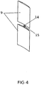
Figure 4 : Conventional perspective view of the slat with its axis and sprocket integral thereto. -
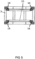
Figure 5 : Section elevation detail of the rotor fastening system to the pair of rails by bogies. -
Figure 6 : Conventional perspective detail of the copying disc. - The numerical references that appear in said figures correspond to the following constituent elements of the invention:
- 1.
- Crossarm structure
- 2.
- Beams
- 3.
- Rotor
- 4.
- Main axis
- 5.
- Multiplier box and alternator
- 6.
- Brake disc
- 7.
- Blades
- 8.
- Metal boxes
- 9.
- Slats
- 10.
- Copying disc
- 11.
- Vane
- 12.
- Toothed strip
- 13.
- Sprocket integral to the slat axis
- 14.
- Axis or mast of the slat
- 15.
- Double rail
- 16.
- Bogies
- 17.
- Rotor cogwheel
- 18.
- Epicyclic gearing
- 19.
- Orientation sprocket
- A preferred embodiment of the system of rotor, transmission and collection elements that optimises a vertical axis wind turbine object of the present invention, with reference to the numerical references, can be based on a structure of crossarms (1) and beams (2) of structural steel or wood, coupled to an electric transport tower, leaving the rotor (3) with its blades (7) at the convenient distance below the conductor support arms, where, at its centre, the main vertical transmission axis (4) is housed and which will be associated with the multiplier box and its alternator (5). Said main axis (4) also integrally incorporates a brake disc (6) that will allow stopping the machine completely.
- The blades (7) are housed at the crown of the rotor (3), and are constituted by four horizontally parallel beams (2), which run from the outer ring of the rotor (3), and are compacted by metal boxes (8) or angle gears inside which the slat (9) guiding mechanisms are housed and support the slats (9) which run from the anchoring mechanism upwards and downwards leaving this support structure in the middle and rotate on it.
- The slats (9) are guided and positioned from a reader mechanism associated with a copying disc (10) positioned by an orientation sprocket (19) of an electronic mechanism associated with a vane (11), and are connected to each other by a toothed strip (12) or axis that forces sprockets (13) integral to the vertical axis (14) of the slat (9). This sprocket (13) is inside the metal boxes (8) and will rotate the slat (9) in the desired direction.
- At the height at which the rotor (3) is set, a platform (1) is elevated, with its anchors and stiffeners, on which a double rail (15) lies, which will serve to move "bogies" (16) or bearings of the rotor (3), which are positioned at different (upper and side) angles so as to prevent the rotor (3) from being dislodged from the double slide rail (15). These bogies (16) are bearings with a specific configuration that allows both radial and axial support to the rotor (3).
- The transmission of force is received from the cogwheel (17) integral to the rotor (3) that transfers that force to an epicyclic gearing (18) and the latter to the main axis (4). The electricity generated by the machine is emptied through conventional power lines.
- In a different embodiment the system is installed on a repeater post or other type of tower.
Claims (9)
- System of rotor, transmission and collection elements that optimises a vertical axis wind turbine, consisting of a structure of crossarms (1) and beams (2) of structural steel or wood, coupled to an electric transport tower characterised in that the rotor (3) with its blades (7) is at a convenient distance below the conductor support arms, and in the centre of which is housed the main vertical axis (4) of transmission, associated to the multiplier box and its alternator (5), and a series of blades (7) equipped with means to regulate their resistance to the passage of air.
- System of rotor, transmission and collection elements that optimises a vertical axis wind turbine, according to claim 1, characterised in that the main axis (4) integrally incorporates a brake disc (6) that allows completely braking the machine.
- System of rotor, transmission and collection elements that optimises a vertical axis wind turbine, according to claims 1 and 2, characterised in that when the multiplier box and the alternator (5) are housed on the ground, the main axis (4) is divided into sections linked by swivel heads.
- System of rotor, transmission and collection elements that optimises a vertical axis wind turbine, according to claims 1 to 3, characterised in that the blades (7) are constituted by four horizontally parallel beams (2), which run from the outer ring of the rotor (3), and are compacted by metal boxes (8) or angle gears inside which the slat (9) guiding mechanisms are housed and support the slats (9) which run from the anchoring mechanism upwards and downwards leaving this support structure in the middle and rotate on it.
- System of rotor, transmission and collection elements that optimises a vertical axis wind turbine, according to claims 1 to 4, characterised in that the slats (9) comprise a rectangular shape inside which they comprise a skeleton that supports this rectangular format having a mast or axis (14) in its centre that penetrates the metal boxes (8) that join the beams (2) and inside link with the mast (14) of the slat (9) of the lower part of the beams (2) with a cogwheel or sprocket (13).
- System of rotor, transmission and collection elements that optimises a vertical axis wind turbine, according to claims 1 to 5, characterised in that the slats (9) are guided and positioned from a reader mechanism associated with a copying disc (10) positioned by an orientation sprocket (19) of an electronic mechanism associated to a vane (11), and they are connected together by a toothed strip (12) or axis that forces the sprockets (13) integral to the vertical axis (14) of the slat (9).
- System of rotor, transmission and collection elements that optimises a vertical axis wind turbine, according to claims 1 to 6, characterised in that the metal boxes (8) that horizontally assemble the beams (2) supporting the slats (9), house within them in a sealed way, the necessary bearings and supports so that both the mast (14) of the slats (9) and the toothed strip (12) that will orient the slats (9) can move.
- System of rotor, transmission and collection elements that optimises a vertical axis wind turbine, according to claims 1 to 7, characterised in that at the height at which the rotor (3) is set, a platform (1) is elevated, with its anchors and stiffeners, on which a double rail (15) lies, which will serve to move "bogies" (16) or bearings (3) of the rotor, which are positioned at different (upper and side) angles so as to prevent the rotor (3) from being dislodged from the double slide rail (15). These bogies (16) are bearings with a specific configuration that allows both radial and axial support to the rotor (3),
- System of rotor, transmission and collection elements that optimises a vertical axis wind turbine, according to claims 1 to 8, characterised in that the transmission of force is received from the cogwheel (17) integral to the rotor (3) that transfers that force to a epicyclic gearing (18) and the latter to the main axis (4).
Applications Claiming Priority (2)
| Application Number | Priority Date | Filing Date | Title |
|---|---|---|---|
| ES201700537U ES1189058Y (en) | 2017-07-17 | 2017-07-17 | Rotor, transmission and pickup system that optimizes the vertical axis wind turbine |
| PCT/ES2018/000058 WO2019016417A1 (en) | 2017-07-17 | 2018-07-03 | System of rotor, transmission and collection elements that optimises a vertical-axis wind turbine |
Publications (2)
| Publication Number | Publication Date |
|---|---|
| EP3657013A1 true EP3657013A1 (en) | 2020-05-27 |
| EP3657013A4 EP3657013A4 (en) | 2021-05-12 |
Family
ID=59384562
Family Applications (1)
| Application Number | Title | Priority Date | Filing Date |
|---|---|---|---|
| EP18836162.0A Withdrawn EP3657013A4 (en) | 2017-07-17 | 2018-07-03 | System of rotor, transmission and collection elements that optimises a vertical-axis wind turbine |
Country Status (10)
| Country | Link |
|---|---|
| US (1) | US11231011B2 (en) |
| EP (1) | EP3657013A4 (en) |
| CN (1) | CN110914531A (en) |
| AU (1) | AU2018303703A1 (en) |
| EA (1) | EA202090214A1 (en) |
| ES (1) | ES1189058Y (en) |
| MA (1) | MA49787A (en) |
| MX (1) | MX2020000540A (en) |
| WO (1) | WO2019016417A1 (en) |
| ZA (1) | ZA201908308B (en) |
Families Citing this family (2)
| Publication number | Priority date | Publication date | Assignee | Title |
|---|---|---|---|---|
| US10975732B2 (en) * | 2019-04-04 | 2021-04-13 | General Electric Company | Rotor turning device for balancing a wind turbine rotor |
| CN112855445B (en) * | 2021-03-12 | 2023-03-10 | 武汉科技大学 | A passive variable pitch vertical axis wind turbine |
Family Cites Families (30)
| Publication number | Priority date | Publication date | Assignee | Title |
|---|---|---|---|---|
| US4979871A (en) * | 1989-11-17 | 1990-12-25 | Reiner Harold E | Wind turbine |
| DE4106976A1 (en) * | 1991-03-05 | 1992-09-10 | Arneth Borros | Wind power plant with rotors on horizontal or vertical axes - has rotors at different levels on HV mast, driving generators connected by transformers etc. to grid lines |
| US6857846B2 (en) * | 2001-06-19 | 2005-02-22 | Lewis H. Miller | Stackable vertical axis windmill |
| AT412808B (en) * | 2003-05-27 | 2005-07-25 | Pius Schubert | Pylon |
| US20050263057A1 (en) * | 2004-06-01 | 2005-12-01 | Green Douglas L | Cyclosail wind turbine |
| GB2425153A (en) * | 2005-04-13 | 2006-10-18 | Leon J Robinson | Wind turbine(s) mounted on a lattice tower |
| EP1957790B1 (en) * | 2005-12-05 | 2013-04-24 | Dulcetti Filho, Flavio Francisco | Eolian converter |
| CN100406719C (en) * | 2006-02-15 | 2008-07-30 | 严强 | Attack angle regulator for vane of vertical shaft wind-driven generator |
| WO2008001273A2 (en) * | 2006-06-30 | 2008-01-03 | Astelio Alunni | Generation of power |
| US20090015015A1 (en) * | 2007-07-09 | 2009-01-15 | Risto Joutsiniemi | Linear power station |
| WO2009106924A2 (en) * | 2008-02-29 | 2009-09-03 | Hopewell Wind Power Limited | Shaftless vertical axis wind turbine |
| BRPI0803335A2 (en) * | 2008-07-16 | 2010-06-08 | Flavio Francisco Dulcetti Jr | wind conversion tower |
| GB2464132B8 (en) * | 2008-10-06 | 2012-09-26 | Microgen Technologies Ltd | Multiple rotor vertical axis wind turbine. |
| US20110062717A1 (en) | 2009-09-16 | 2011-03-17 | Price Jr Arnold | Urility grid vertical axis wind turbine system |
| CN201568205U (en) * | 2009-12-04 | 2010-09-01 | 陈超 | A wind energy rotating device |
| CN101749190A (en) * | 2009-12-14 | 2010-06-23 | 江苏省信息化研究中心 | Center fixed-supporting vertical axis wind turbine |
| CN102192091A (en) * | 2010-03-08 | 2011-09-21 | 王德恒 | Split type vertical axis wind driven generator system |
| CN101943120B (en) * | 2010-06-12 | 2013-02-13 | 彭勇 | Abrasive disc type wind turbine |
| CN102817783A (en) * | 2011-06-08 | 2012-12-12 | 张俊华 | Vertical axis tube type wind generator |
| CN102162427B (en) * | 2011-06-08 | 2012-10-31 | 南通大学 | Vertical axis wind turbine rotor with adjustable blade inclination angle |
| FR2985290B1 (en) * | 2012-01-02 | 2016-07-15 | Soc Financiere Gerard Allot | VERTICAL AXLE WIND |
| CN202520483U (en) * | 2012-04-20 | 2012-11-07 | 温州欧特莱科技有限公司 | Vertical shaft type wind driven generator with brake system |
| EP2844869A4 (en) * | 2012-05-04 | 2016-05-18 | Wind Energy Corp | Wind turbine system and method of operating a wind turbine system |
| GB2510554B (en) * | 2012-11-26 | 2016-03-09 | Supervawt Ltd | Turbine with Two Part Blade having Pitch and Camber Control |
| CN102979667A (en) * | 2012-12-28 | 2013-03-20 | 天津市宝坻区同利服装辅料厂 | Wind turbine impeller |
| EP3142208A1 (en) * | 2015-03-10 | 2017-03-15 | Martin Grogan | A pylon based power management system |
| US10823140B2 (en) * | 2015-11-06 | 2020-11-03 | Linton K. Samarasinha | Vertical axis wind turbine structure |
| CN105649871B (en) * | 2016-01-07 | 2019-01-01 | 上海理工大学 | Double-blade type vertical axis aerogenerator |
| ES2624727B1 (en) * | 2016-01-13 | 2018-04-30 | Josë Antonio TORRECILLA CONTRERAS | Dual axis wind turbine pickup system |
| CN105840430A (en) * | 2016-06-01 | 2016-08-10 | 河南理工大学 | Small vertical shaft magnetic suspension wind driven generator |
-
2017
- 2017-07-17 ES ES201700537U patent/ES1189058Y/en not_active Expired - Fee Related
-
2018
- 2018-07-03 EP EP18836162.0A patent/EP3657013A4/en not_active Withdrawn
- 2018-07-03 AU AU2018303703A patent/AU2018303703A1/en not_active Abandoned
- 2018-07-03 CN CN201880047270.4A patent/CN110914531A/en active Pending
- 2018-07-03 US US16/626,637 patent/US11231011B2/en active Active
- 2018-07-03 MA MA049787A patent/MA49787A/en unknown
- 2018-07-03 EA EA202090214A patent/EA202090214A1/en unknown
- 2018-07-03 WO PCT/ES2018/000058 patent/WO2019016417A1/en not_active Ceased
- 2018-07-03 MX MX2020000540A patent/MX2020000540A/en unknown
-
2019
- 2019-12-12 ZA ZA2019/08308A patent/ZA201908308B/en unknown
Also Published As
| Publication number | Publication date |
|---|---|
| MX2020000540A (en) | 2020-09-10 |
| EA202090214A1 (en) | 2020-04-17 |
| WO2019016417A1 (en) | 2019-01-24 |
| ES1189058Y (en) | 2017-10-20 |
| US20200158079A1 (en) | 2020-05-21 |
| MA49787A (en) | 2020-05-27 |
| ES1189058U (en) | 2017-08-01 |
| US11231011B2 (en) | 2022-01-25 |
| ZA201908308B (en) | 2021-05-26 |
| AU2018303703A1 (en) | 2020-01-23 |
| EP3657013A4 (en) | 2021-05-12 |
| CN110914531A (en) | 2020-03-24 |
Similar Documents
| Publication | Publication Date | Title |
|---|---|---|
| US4036916A (en) | Wind driven electric power generator | |
| US9222462B2 (en) | Wind turbine | |
| AU2010339143B2 (en) | Wind turbine | |
| US7944075B2 (en) | Wind turbine based energy storage system and method using heavy weighted devices | |
| US20110042958A1 (en) | Collapsible vertical-axis turbine | |
| US20110107684A1 (en) | Pole mounted rotation platform and wind power generator | |
| US20130223964A1 (en) | Tower-based platform system for lifting components atop a wind turbine tower | |
| CN102418673A (en) | Wind driven generator system with generator set mounted on land | |
| US20110037271A1 (en) | Wind turbine system and modular wind turbine unit therefor | |
| CA2709723A1 (en) | System and method for electrical power generation from renewable energy sources | |
| US11231011B2 (en) | System of rotor, transmission and collection elements that optimises a vertical axis wind turbine | |
| US8604635B2 (en) | Vertical axis wind turbine for energy storage | |
| KR101325752B1 (en) | High Performance Counter Rotating Gearless Vertical Axis Wind Power Generator using Active Intelligent Dual Turbine Blade Layers | |
| RU2539604C2 (en) | Wind-driven power plant | |
| RU114106U1 (en) | WIND POWER MODULE | |
| CN102235302A (en) | Wind-collecting wind wheel device and wind power generation equipment | |
| JP2013527361A (en) | Wind turbine system | |
| RU40769U1 (en) | AUTONOMOUS WIND POWER INSTALLATION | |
| KR20130136027A (en) | Aerogenerator | |
| US20130056990A1 (en) | Modular Wind Turbine | |
| KR101337360B1 (en) | Vertical Wind Power Generation Apparatus For High-efficiency | |
| GB2491853A (en) | Modular wind turbine system with repositionable turbines | |
| ES2624727B1 (en) | Dual axis wind turbine pickup system | |
| US11898537B2 (en) | Wind generator | |
| US8446033B1 (en) | Savonius rotor wind power generator system and method |
Legal Events
| Date | Code | Title | Description |
|---|---|---|---|
| STAA | Information on the status of an ep patent application or granted ep patent |
Free format text: STATUS: THE INTERNATIONAL PUBLICATION HAS BEEN MADE |
|
| PUAI | Public reference made under article 153(3) epc to a published international application that has entered the european phase |
Free format text: ORIGINAL CODE: 0009012 |
|
| STAA | Information on the status of an ep patent application or granted ep patent |
Free format text: STATUS: REQUEST FOR EXAMINATION WAS MADE |
|
| 17P | Request for examination filed |
Effective date: 20200117 |
|
| AK | Designated contracting states |
Kind code of ref document: A1 Designated state(s): AL AT BE BG CH CY CZ DE DK EE ES FI FR GB GR HR HU IE IS IT LI LT LU LV MC MK MT NL NO PL PT RO RS SE SI SK SM TR |
|
| A4 | Supplementary search report drawn up and despatched |
Effective date: 20210414 |
|
| RIC1 | Information provided on ipc code assigned before grant |
Ipc: F03D 9/43 20160101AFI20210408BHEP Ipc: F03D 3/00 20060101ALI20210408BHEP Ipc: F03D 3/06 20060101ALI20210408BHEP |
|
| STAA | Information on the status of an ep patent application or granted ep patent |
Free format text: STATUS: THE APPLICATION IS DEEMED TO BE WITHDRAWN |
|
| 18D | Application deemed to be withdrawn |
Effective date: 20211116 |