EP3656987A1 - Method for calculating and method for monitoring the creep elongation of a rotor - Google Patents
Method for calculating and method for monitoring the creep elongation of a rotor Download PDFInfo
- Publication number
- EP3656987A1 EP3656987A1 EP18208171.1A EP18208171A EP3656987A1 EP 3656987 A1 EP3656987 A1 EP 3656987A1 EP 18208171 A EP18208171 A EP 18208171A EP 3656987 A1 EP3656987 A1 EP 3656987A1
- Authority
- EP
- European Patent Office
- Prior art keywords
- creep elongation
- rotor
- temperature
- creep
- ref
- Prior art date
- Legal status (The legal status is an assumption and is not a legal conclusion. Google has not performed a legal analysis and makes no representation as to the accuracy of the status listed.)
- Granted
Links
Images

Classifications
-
- G—PHYSICS
- G01—MEASURING; TESTING
- G01M—TESTING STATIC OR DYNAMIC BALANCE OF MACHINES OR STRUCTURES; TESTING OF STRUCTURES OR APPARATUS, NOT OTHERWISE PROVIDED FOR
- G01M13/00—Testing of machine parts
-
- F—MECHANICAL ENGINEERING; LIGHTING; HEATING; WEAPONS; BLASTING
- F01—MACHINES OR ENGINES IN GENERAL; ENGINE PLANTS IN GENERAL; STEAM ENGINES
- F01D—NON-POSITIVE DISPLACEMENT MACHINES OR ENGINES, e.g. STEAM TURBINES
- F01D21/00—Shutting-down of machines or engines, e.g. in emergency; Regulating, controlling, or safety means not otherwise provided for
- F01D21/003—Arrangements for testing or measuring
-
- G—PHYSICS
- G01—MEASURING; TESTING
- G01B—MEASURING LENGTH, THICKNESS OR SIMILAR LINEAR DIMENSIONS; MEASURING ANGLES; MEASURING AREAS; MEASURING IRREGULARITIES OF SURFACES OR CONTOURS
- G01B11/00—Measuring arrangements characterised by the use of optical techniques
- G01B11/16—Measuring arrangements characterised by the use of optical techniques for measuring the deformation in a solid, e.g. optical strain gauge
-
- F—MECHANICAL ENGINEERING; LIGHTING; HEATING; WEAPONS; BLASTING
- F05—INDEXING SCHEMES RELATING TO ENGINES OR PUMPS IN VARIOUS SUBCLASSES OF CLASSES F01-F04
- F05D—INDEXING SCHEME FOR ASPECTS RELATING TO NON-POSITIVE-DISPLACEMENT MACHINES OR ENGINES, GAS-TURBINES OR JET-PROPULSION PLANTS
- F05D2260/00—Function
- F05D2260/80—Diagnostics
Definitions
- the present invention relates to a method for calculating and a method for monitoring the creep elongation of a rotor.
- Reduction of the clearances can influence the operation parameters and cooling and could also cause interference between rotor or components connected to it and stator or components connected to it.
- An aspect of the invention includes providing a method that allows the calculation of the creep elongation of a rotor according to the real working condition it undergoes during operation.
- Another aspect of the invention includes providing a method by which the creep elongation of the rotor can be monitored.
- the creep elongation U r is the total permanent growth the rotor undergoes during operation; incremental creep elongation ⁇ U r (or dU r ) is the permanent growth the rotor undergoes between two successive sampling moments, rate of creep elongation is defined by ⁇ U r / ⁇ t (or dU r /dt) (where t is time).
- the rate of creep elongation in the radial direction can be written as a function of average temperature and average stress along the radius. This assumption can be implemented by considering a control volume covering the entire rotor radius with an infinitesimal circumferential length.
- the parameters in the equation of the rate of creep elongation will be average temperature and average stress over the rotor radius (equation 2) : dU r t dt ⁇ ⁇ 0 R T metal r d r and ⁇ 0 R ⁇ e r t d r
- ⁇ 0 R ⁇ e r t dr can be replaced with the radial displacement or creep elongation U r . This is a prerequisite considering that the stress can be difficult to measure or calculate for any operation.
- Finite elements simulations can be carried out to provide the correlation f(T ref , Load, U r ) of equation 4, for example in the form of tabular factors, formula or fitting surfaces.
- rotor has to be interpreted as a rotating cylindrical component belonging to a gas turbine or not, i.e. it can also be part of a machine different from a gas turbine.
- FIG. 1 schematically shows a gas turbine 1, which comprises a compressor 2 that is supplied with air 3 from the ambient 4 (external ambient); the compressor 2 supplies compressed air to a first combustion chamber 6, in which a fuel 7 is fed, mixed with the compressed air and combusted, generating first hot gas 8 that is fed in a mixer 9 where dilution air 10 is fed and mixed with the first hot gas 8, generating second hot gas 11 that is supplied into a second combustor 12.
- the second combustor 12 further fuel 14 is supplied, mixed with the second hot gas 11 and combusted, generated third hot gas 15 that is expanded in a turbine 16, which collects mechanical power, e.g. to activate an electrical generator 17.
- Exhaust gas 18 is discharged from the turbine 16.
- gas turbine is only one of the possible types of gas turbines, it is clear that the method of the invention is not limited to this kind of gas turbine but can be applied to any gas turbine, e.g. comprising only a compressor, a combustion chamber and a turbine, or comprising a compressor a first combustion chamber, a first high pressure turbine, a second combustion chamber and a second low pressure turbine; further examples of gas turbine are possible.
- the method for calculating the creep elongation at a given cross section of a rotor comprises providing, for that cross section, a correlation among:
- the temperature is periodically measured at successive sampling moments i; for example the measurement can be made every 10 minutes or 5 minutes or also every minute; any value for the sampling frequency is possible anyway according to the requirements.
- the creep elongation U r for the given cross section of the rotor at the sampling moment i is thus calculated on the basis of the correlation using the equation 7, having as the inputs the measured value of the reference temperature T Ref at the sampling moment i and the creep elongation U r at the sampling moment i-1.
- the correlation can be established for each cross section that is to be monitored on the basis of pre-defined ambient and load conditions.
- the correlation can be defined by curves ( figure 2 ) or look-up tables ( figure 4 ) that provide a relationship among the different factors.
- the figures 2 , 4 are representative of correlations at a given cross section of the rotor.
- the reference temperature T Ref is preferably a gas temperature, because this temperature can be easily and reliably measured.
- the reference temperature T Ref (being a gas temperature) is the gas temperature at a zone adjacent and facing the given cross section.
- the reference temperature T Ref (also being a gas temperature) is the temperature at the outlet of the compressor (this temperature is identified as Tk2), because this temperature is known and controlled and because on the basis of this temperature and using an imperial or analytical function or a state of the art gas turbine simulation software, such as the software NX available from Siemens, the temperatures at any position of the rotor can be calculated.
- the correlation has to include both load of the gas turbine and the reference temperature T Ref ; therefore in this case the correlation ( figure 3 ) is provided among:
- figure 3 shows a three-dimensional surface that defines the correlation among the different factors.
- the temperature is periodically measured at successive sampling moments i and the creep elongation U r for the given cross section of the rotor at the sampling moment i is calculated on the basis of the correlation using the equation 6; in this case the inputs are the measured value of the reference temperature T Ref at the sampling moment i, the load of the gas turbine at the sampling moment i and the creep elongation U r at the sampling moment i-1.
- the correlation can be defined by surfaces ( figure 3 ) or look-up tables that provide a relationship among the different factors.
- the reference temperature T Ref is preferably a gas temperature, because this temperature can be easily and reliably measured.
- the gas temperature is the ambient temperature, i.e. the temperature of the ambient external to the gas turbine 1, because this temperature is known and on the basis of this temperature and the load of the gas turbine, the temperatures at any position of the rotor can be calculated, for example using an imperial or analytical function or a state of the art gas turbine simulation software, such as NX available from Siemens.
- the method is implemented via a computer readable medium stored and running on a computer (e.g. laptop, desktop, tablet, dedicated electronics, etc.).
- the computer readable medium e.g. a software
- the computer readable medium has instructions for calculating the creep elongation according to the described method for calculating.
- the correlation can be calculated in successive steps.
- boundary conditions for the operation of the gas turbine are provided; on the basis of these boundary conditions, state of the art gas turbine simulation methods are used to calculate the thermal conditions of the rotor.
- the following software can be used to simulate the gas turbine: NX produced by Siemens.
- the reference temperature can be calculated.
- the calculated thermal condition of the rotor is supplied as an input to a finite element method equipped with creep law, in order to calculate the rate of creep elongation over the rotor associated with the thermal conditions calculated at the first step.
- the finite element method equipped with material creep law (this is a state of the art software) can calculate the rate of creep elongation over the whole rotor.
- the following software can be used as a finite element method with creep law: Abaqus produced by SIMULIA.
- the creep elongation can be calculated from the rate of creep elongation.
- the curves or look-up tables or other representing the correlation can be built using the calculated values of the rate of creep elongation and the given inputs (reference temperature T Ref , load) and the calculated creep elongation.
- each curve refers to a reference temperature T Ref ( figure 2 ) and provides the relationship between that reference temperature T Ref , creep elongation U r and rate of creep elongation ⁇ U r / ⁇ t.
- each surface refers to a reference temperature T Ref and provides the relationship among that reference temperature T Ref , load, creep elongation U r and rate of creep elongation ⁇ U r / ⁇ t.
- the present invention also refers to a method for monitoring a creep elongation of a rotor.
- the method comprises
- This measurement can be done during operation of the gas turbine; in this connection the gas turbine can be provided with a laser emitter that focuses a laser beam on the rotor; the rotor reflects the laser beam and the reflected laser beam is collected by a laser receiver; a control system connected to the laser emitter and laser receiver can calculate the deformation of the rotor of the basis of the angles between the emitted laser beam and the received laser beam. Other techniques are naturally possible.
- the measured creep elongation can be measured during an outage of the machine.
- the creep elongation can e.g. be measured by measuring tape.
- protective actions can be implemented in case the measured creep elongation is larger than the calculated creep elongation.
- These protective actions can include the emission of alarm signals and/or the stop and/or the reduction of the gas turbine load in case the gas turbine is in operation, or the emission of alarm signals or provision of safety boundary conditions for the gas turbine operation. Other measures are naturally possible.
- the method is implemented via a computer readable medium.
- a computer readable medium e.g. a software
- the computer readable medium is stored on and runs on a computer (e.g. laptop, desktop, tablet, dedicated electronics, etc.).
- the calculations are made on the basis of the initial diameter of the rotor, i.e. the creep elongation refers to the original diameter of the rotor before its first operation.
Landscapes
- Physics & Mathematics (AREA)
- General Physics & Mathematics (AREA)
- Engineering & Computer Science (AREA)
- Mechanical Engineering (AREA)
- General Engineering & Computer Science (AREA)
- Investigating Strength Of Materials By Application Of Mechanical Stress (AREA)
Abstract
Description
- The present invention relates to a method for calculating and a method for monitoring the creep elongation of a rotor.
- During operation of a gas turbine the rotor undergoes large thermal and mechanical stresses, which cause its deformation in the form of a permanent radial elongation or expansion; this elongation is known as creep deformation, creep growth or creep elongation.
- Calculating and monitoring the creep elongation is of the uttermost importance, because creep elongation causes an increase of the diameter of the rotor and therefore a reduction, over time, of the clearances between the rotor or components connected thereto and the stator or components connected thereto. Also it can be used as indication of the consumed creep lifetime.
- Reduction of the clearances can influence the operation parameters and cooling and could also cause interference between rotor or components connected to it and stator or components connected to it.
- An aspect of the invention includes providing a method that allows the calculation of the creep elongation of a rotor according to the real working condition it undergoes during operation.
- Another aspect of the invention includes providing a method by which the creep elongation of the rotor can be monitored.
- These and further aspects are attained by providing a method for calculating and a method for monitoring in accordance with the accompanying claims.
- Further characteristics and advantages will be more apparent from the description of a preferred but non-exclusive embodiment of the method for calculating and method for monitoring the rotor creep elongation, illustrated by way of non-limiting example in the accompanying drawings, in which:
-
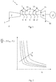
Figure 1 schematically shows a gas turbine; -
Figure 2 shows a diagram providing a correlation for a given cross section among a reference temperature TRef, a creep elongation Ur , and rate of creep elongation ΔUr /Δt=f(Ur , Tref); -
Figure 3 shows a diagram providing a correlation for a given cross section among a reference temperature TRef, the gas turbine load, the creep elongation Ur , and rate of creep elongation ΔUr /Δt=f(Tref, Load, Ur ); -
Figure 4 shows a look-up table providing the relationship (correlation) for a given cross section among a reference temperature TRef, a creep elongation Ur , an rate of creep elongation ΔUr /Δt, -
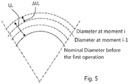
Figure 5 schematically shows the creep elongation and the incremental creep elongation of a rotor. - With reference to
figure 5 , the creep elongation Ur is the total permanent growth the rotor undergoes during operation; incremental creep elongation ΔUr (or dUr) is the permanent growth the rotor undergoes between two successive sampling moments, rate of creep elongation is defined by ΔUr /Δt (or dUr/dt) (where t is time). - The rate of rotor radial creep elongation can be calculated from the strain rate integration over the radius of the rotor as (equation 1):

- dUr/dt is the rate of creep elongation of the rotor in the radial direction,
- dε/dt is the strain rate,
- σ is the stress through the rotor,
- T is the local, metal temperature of the rotor.
- Since both stress and temperature in a rotor heated from the outside vary with the radial distance from the axis of the rotor, the strain rate also changes with the radial distance from the axis of the rotor.
- Thus, the rate of creep elongation in the radial direction can be written as a function of average temperature and average stress along the radius. This assumption can be implemented by considering a control volume covering the entire rotor radius with an infinitesimal circumferential length. In this case the parameters in the equation of the rate of creep elongation will be average temperature and average stress over the rotor radius (equation 2) :

- In this equation,

- With these assumptions, the
equation 2 can be written as (equation 3):
- Furthermore, since it is difficult to measure the metal temperature in rotating components (i.e. the temperature of the rotor), and since the metal temperature of the rotor in general depends on a reference temperature and the load of the gas turbine, the
equation 3 can be written as (equation 4):
- Finite elements simulations can be carried out to provide the correlation f(Tref, Load, Ur) of
equation 4, for example in the form of tabular factors, formula or fitting surfaces. - Once the correlation f(Tref, Load, Ur) has been obtained, the creep elongation at a given cross section of the rotor can be calculated as (equation 5):

- Since TRef is measured at a given time interval during the gas turbine operation, the integral in the equation 5 can be discretized and solved incrementally. In addition, considering that


- If the effect of reference temperature TRef and load on the rate of creep elongation of the rotor is judged to be the same, the
equation 6 can be written only in dependence of the reference temperature, because the effect of the load is implicitly included together with the Tref (equation 7):
- Otherwise if the effect of ambient temperature TRef and load on the rate of creep elongation of the rotor is judged to be different, the
equation 6 has to be used for calculating the creep elongation. - In the following reference to a rotor of a gas turbine is made. It is clear that rotor has to be interpreted as a rotating cylindrical component belonging to a gas turbine or not, i.e. it can also be part of a machine different from a gas turbine.
-
Figure 1 schematically shows agas turbine 1, which comprises acompressor 2 that is supplied withair 3 from the ambient 4 (external ambient); thecompressor 2 supplies compressed air to afirst combustion chamber 6, in which a fuel 7 is fed, mixed with the compressed air and combusted, generating firsthot gas 8 that is fed in amixer 9 wheredilution air 10 is fed and mixed with the firsthot gas 8, generating secondhot gas 11 that is supplied into asecond combustor 12. In thesecond combustor 12further fuel 14 is supplied, mixed with the secondhot gas 11 and combusted, generated thirdhot gas 15 that is expanded in aturbine 16, which collects mechanical power, e.g. to activate anelectrical generator 17.Exhaust gas 18 is discharged from theturbine 16. - The above described embodiment of gas turbine is only one of the possible types of gas turbines, it is clear that the method of the invention is not limited to this kind of gas turbine but can be applied to any gas turbine, e.g. comprising only a compressor, a combustion chamber and a turbine, or comprising a compressor a first combustion chamber, a first high pressure turbine, a second combustion chamber and a second low pressure turbine; further examples of gas turbine are possible.
- With the judgment that TRef and load have the same effect on the rate of creep elongation, the method for calculating the creep elongation at a given cross section of a rotor comprises providing, for that cross section, a correlation among:
- (i) a reference temperature TRef indicative of the temperature of the rotor at the given cross section,
- (ii) a creep elongation Ur of the rotor,
- (iii) a rate of creep elongation ΔUr /Δt.
- Thus, according to the method, the temperature is periodically measured at successive sampling moments i; for example the measurement can be made every 10 minutes or 5 minutes or also every minute; any value for the sampling frequency is possible anyway according to the requirements.
- The creep elongation Ur for the given cross section of the rotor at the sampling moment i is thus calculated on the basis of the correlation using the equation 7, having as the inputs the measured value of the reference temperature TRef at the sampling moment i and the creep elongation Ur at the sampling moment i-1.
- The correlation can be established for each cross section that is to be monitored on the basis of pre-defined ambient and load conditions. For example, the correlation can be defined by curves (
figure 2 ) or look-up tables (figure 4 ) that provide a relationship among the different factors. In this case thefigures 2 ,4 are representative of correlations at a given cross section of the rotor. - The reference temperature TRef is preferably a gas temperature, because this temperature can be easily and reliably measured.
- In a first example the reference temperature TRef (being a gas temperature) is the gas temperature at a zone adjacent and facing the given cross section.
- In a second example the reference temperature TRef (also being a gas temperature) is the temperature at the outlet of the compressor (this temperature is identified as Tk2), because this temperature is known and controlled and because on the basis of this temperature and using an imperial or analytical function or a state of the art gas turbine simulation software, such as the software NX available from Siemens, the temperatures at any position of the rotor can be calculated.
- With the judgment that load and reference temperature TRef have a different effect of the rate of creep elongation, the correlation has to include both load of the gas turbine and the reference temperature TRef; therefore in this case the correlation (
figure 3 ) is provided among: - (i) a reference temperature TRef indicative of the component temperature at a given cross section,
- (ii) a creep elongation Ur of the rotor,
- (iii) a rate of creep elongation ΔUr/Δt,
- (iv) the load of the gas turbine.
- In this respect
figure 3 shows a three-dimensional surface that defines the correlation among the different factors. - Also in this case, the temperature is periodically measured at successive sampling moments i and the creep elongation Ur for the given cross section of the rotor at the sampling moment i is calculated on the basis of the correlation using the
equation 6; in this case the inputs are the measured value of the reference temperature TRef at the sampling moment i, the load of the gas turbine at the sampling moment i and the creep elongation Ur at the sampling moment i-1. - In this case the correlation can be defined by surfaces (
figure 3 ) or look-up tables that provide a relationship among the different factors. - The reference temperature TRef is preferably a gas temperature, because this temperature can be easily and reliably measured.
- For example, the gas temperature is the ambient temperature, i.e. the temperature of the ambient external to the
gas turbine 1, because this temperature is known and on the basis of this temperature and the load of the gas turbine, the temperatures at any position of the rotor can be calculated, for example using an imperial or analytical function or a state of the art gas turbine simulation software, such as NX available from Siemens. - In a preferred and advantageous embodiment, the method is implemented via a computer readable medium stored and running on a computer (e.g. laptop, desktop, tablet, dedicated electronics, etc.). In this connection, the computer readable medium (e.g. a software) has instructions for calculating the creep elongation according to the described method for calculating.
- The correlation can be calculated in successive steps.
- In a first step, boundary conditions for the operation of the gas turbine (ambient temperature and load) are provided; on the basis of these boundary conditions, state of the art gas turbine simulation methods are used to calculate the thermal conditions of the rotor. As an example, the following software can be used to simulate the gas turbine: NX produced by Siemens. In addition, since from this step all thermal features can be obtained, also the reference temperature can be calculated.
- In a second step, the calculated thermal condition of the rotor is supplied as an input to a finite element method equipped with creep law, in order to calculate the rate of creep elongation over the rotor associated with the thermal conditions calculated at the first step.
- The finite element method equipped with material creep law (this is a state of the art software) can calculate the rate of creep elongation over the whole rotor. The following software can be used as a finite element method with creep law: Abaqus produced by SIMULIA.
- These steps can be repeated a number of times in order to calculate the rate of creep elongation for different boundary conditions of the first step (ambient temperature and/or gas turbine load).
- Also the creep elongation can be calculated from the rate of creep elongation.
- Thus, For each cross section of interest, the curves or look-up tables or other representing the correlation can be built using the calculated values of the rate of creep elongation and the given inputs (reference temperature TRef, load) and the calculated creep elongation.
- For example between five and ten cross sections are monitored and thus the correlations are calculated for them, e.g. at the compressor, at the turbine and preferably also in correspondence of the combustion chamber(s).
- When the influence of the ambient temperature and load on the rate of creep elongation is judged to be the same or substantially the same, the load of the gas turbine can be disregarded and the correlation is defined by different curves for different values of the reference temperature TRef, as visible in
figure 2 . Each curve refers to a reference temperature TRef (figure 2 ) and provides the relationship between that reference temperature TRef, creep elongation Ur and rate of creep elongation ΔUr /Δt. - When the influence of the reference temperature TRef and load on the rate of creep elongation is judged to be different, different surfaces can be calculated for different values of the reference temperature TRef and load, as visible in
figure 3 ; infigure 3 each surface refers to a reference temperature TRef and provides the relationship among that reference temperature TRef, load, creep elongation Ur and rate of creep elongation ΔUr /Δt. - Naturally, even if the attached
figures 2 and3 provide a correlation depicted as a curves or surfaces, look-up tables, such as those shown infigure 4 , or other graphical or numerical or other representations are also possible. - The present invention also refers to a method for monitoring a creep elongation of a rotor.
- The method comprises
- a. calculating the creep elongation according to the method for calculating the creep elongation described above,
- b. measuring a creep elongation of the rotor,
- c. comparing the calculated creep elongation with the measured creep elongation,
- d. ascertaining whether the measured creep elongation is larger than the calculated creep elongation.
- The measurement of the creep elongation required under point b. above can be done in different ways.
- This measurement can be done during operation of the gas turbine; in this connection the gas turbine can be provided with a laser emitter that focuses a laser beam on the rotor; the rotor reflects the laser beam and the reflected laser beam is collected by a laser receiver; a control system connected to the laser emitter and laser receiver can calculate the deformation of the rotor of the basis of the angles between the emitted laser beam and the received laser beam. Other techniques are naturally possible.
- In addition, the measured creep elongation can be measured during an outage of the machine. In this case the creep elongation can e.g. be measured by measuring tape.
- On the basis of the ascertainment under point d., protective actions can be implemented in case the measured creep elongation is larger than the calculated creep elongation. These protective actions can include the emission of alarm signals and/or the stop and/or the reduction of the gas turbine load in case the gas turbine is in operation, or the emission of alarm signals or provision of safety boundary conditions for the gas turbine operation. Other measures are naturally possible.
- In a preferred embodiment, the method is implemented via a computer readable medium. In this preferred embodiment, a computer readable medium (e.g. a software) has instructions for monitoring the creep elongation according to the described method for monitoring. The computer readable medium is stored on and runs on a computer (e.g. laptop, desktop, tablet, dedicated electronics, etc.).
- In a preferred advantageous embodiment, the calculations are made on the basis of the initial diameter of the rotor, i.e. the creep elongation refers to the original diameter of the rotor before its first operation.
- Naturally the features described may be independently provided from one another. For example, the features of each of the attached claims can be applied independently of the features of the other claims.
- In practice the materials used and the dimensions can be chosen at will according to requirements and to the state of the art.
Claims (12)
- A method for calculating a creep elongation of a rotor, the method comprisinga. providing a correlation for a given cross section of the rotor among∘ a reference temperature (TRef) indicative of the temperature of the rotor,∘ a creep elongation (Ur ),∘ a rate of creep elongation (ΔUr /Δt),b. measuring the reference temperature (TRef) at a sampling moment i;c. calculating on the basis of the correlation the creep elongation (Ur) of the rotor at the sampling moment i on the basis of the measured reference temperature (TRef) at the sampling moment i and the creep elongation at the sampling moment i-1.
- The method of claim 1, characterized in that the reference temperature is a gas temperature.
- The method of claim 2, characterized in that the gas temperature is a temperature at the outlet of the compressor of a gas turbine (Tk2i).
- The method of claim 1 or 2, characterized in that the correlation further includes the load of the gas turbine.
- The method of claim 4, characterized in that the gas temperature is an ambient temperature.
- The method of claim any of the previous claims, characterized in that the machine is a gas turbine.
- A computer readable medium stored and/or running on a computer comprising instructions for calculating the creep elongation according to the method of any of claims 1 to 6.
- A method for monitoring a creep elongation of a rotor, the method comprisinga. calculating the creep elongation of the rotor according to the method of any of claims 1 to 6,b. measuring a creep elongation of the rotor,c. comparing the calculated creep elongation with the measured creep elongation,d. ascertaining whether the measured creep elongation is larger than the calculated creep elongation.
- The method of claim 8, characterized in that measuring the creep elongation is done during the operation of the machine.
- The method of claim 8, characterized in that measuring the creep elongation is done during an outage of the machine.
- The method of any of claims 8 through 10, characterized by implementing protective actions in case the measured creep elongation is larger than the calculated creep elongation.
- A computer readable medium stored and/or running on a computer comprising instructions for monitoring the creep elongation according to the method of any of claims 8 to 11.
Priority Applications (2)
| Application Number | Priority Date | Filing Date | Title |
|---|---|---|---|
| EP18208171.1A EP3656987B1 (en) | 2018-11-23 | 2018-11-23 | Method for calculating and method for monitoring the creep elongation of a rotor |
| CN201911156373.7A CN111220364B (en) | 2018-11-23 | 2019-11-22 | Method for calculating creep elongation of rotor and method for monitoring creep elongation of rotor |
Applications Claiming Priority (1)
| Application Number | Priority Date | Filing Date | Title |
|---|---|---|---|
| EP18208171.1A EP3656987B1 (en) | 2018-11-23 | 2018-11-23 | Method for calculating and method for monitoring the creep elongation of a rotor |
Publications (2)
| Publication Number | Publication Date |
|---|---|
| EP3656987A1 true EP3656987A1 (en) | 2020-05-27 |
| EP3656987B1 EP3656987B1 (en) | 2022-01-05 |
Family
ID=64456909
Family Applications (1)
| Application Number | Title | Priority Date | Filing Date |
|---|---|---|---|
| EP18208171.1A Active EP3656987B1 (en) | 2018-11-23 | 2018-11-23 | Method for calculating and method for monitoring the creep elongation of a rotor |
Country Status (2)
| Country | Link |
|---|---|
| EP (1) | EP3656987B1 (en) |
| CN (1) | CN111220364B (en) |
Families Citing this family (3)
| Publication number | Priority date | Publication date | Assignee | Title |
|---|---|---|---|---|
| EP4012160A1 (en) * | 2020-12-11 | 2022-06-15 | Ansaldo Energia Switzerland AG | Method for estimating the consumed life of a rotating component |
| CN113028969B (en) * | 2021-05-24 | 2021-08-17 | 天津飞旋科技股份有限公司 | Method and device for measuring rotor elongation |
| CN113804094B (en) * | 2021-09-22 | 2022-08-09 | 本元智慧科技有限公司 | Device and method for estimating elongation of rotor of magnetic suspension motor |
Citations (2)
| Publication number | Priority date | Publication date | Assignee | Title |
|---|---|---|---|---|
| CH706827A2 (en) * | 2012-08-14 | 2014-02-14 | Gen Electric | Kriechlebensdauermanagementsystem for a turbine and method of operating the same. |
| US8770913B1 (en) * | 2010-06-17 | 2014-07-08 | Florida Turbine Technologies, Inc. | Apparatus and process for rotor creep monitoring |
Family Cites Families (5)
| Publication number | Priority date | Publication date | Assignee | Title |
|---|---|---|---|---|
| US5042295A (en) * | 1985-06-21 | 1991-08-27 | General Electric Company | Method for determining remaining useful life of turbine components |
| JPH06200701A (en) * | 1992-12-29 | 1994-07-19 | Mitsubishi Heavy Ind Ltd | Remaining lifetime diagnostic method for steam turbine rotor |
| US8364425B2 (en) * | 2005-07-05 | 2013-01-29 | Ohio University | Method and system for determining properties of an asphalt material |
| US7787996B2 (en) * | 2008-01-10 | 2010-08-31 | General Electric Company | Determining optimal turbine operating temperature based on creep rate data and predicted revenue data |
| US8746049B2 (en) * | 2011-09-06 | 2014-06-10 | General Electric Company | Creep indication system and method for determining creep amount |
-
2018
- 2018-11-23 EP EP18208171.1A patent/EP3656987B1/en active Active
-
2019
- 2019-11-22 CN CN201911156373.7A patent/CN111220364B/en active Active
Patent Citations (2)
| Publication number | Priority date | Publication date | Assignee | Title |
|---|---|---|---|---|
| US8770913B1 (en) * | 2010-06-17 | 2014-07-08 | Florida Turbine Technologies, Inc. | Apparatus and process for rotor creep monitoring |
| CH706827A2 (en) * | 2012-08-14 | 2014-02-14 | Gen Electric | Kriechlebensdauermanagementsystem for a turbine and method of operating the same. |
Non-Patent Citations (2)
| Title |
|---|
| EVANS M: "A generalised Monkman-Grant relation for creep life prediction: An application to 1CrMoV rotor steel", JOURNAL OF MATERIALS SCIENCE, KLUWER ACADEMIC PUBLISHERS, BO, vol. 41, no. 12, 12 April 2006 (2006-04-12), pages 3907 - 3915, XP019398969, ISSN: 1573-4803, DOI: 10.1007/S10853-005-5506-7 * |
| KAZUHIRO KIMURA ET AL: "Creep Deformation, Rupture Strength, and Rupture Ductility of Grades T/P92 Steels", ASME 2014 SYMPOSIUM ON ELEVATED TEMPERATURE APPLICATION OF MATERIALS FOR FOSSIL, NUCLEAR, AND PETROCHEMICAL INDUSTRIES, 25 March 2014 (2014-03-25), pages 193, XP055576598, ISBN: 978-0-7918-4074-0, DOI: 10.1115/ETAM2014-1026 * |
Also Published As
| Publication number | Publication date |
|---|---|
| EP3656987B1 (en) | 2022-01-05 |
| CN111220364B (en) | 2024-07-26 |
| CN111220364A (en) | 2020-06-02 |
Similar Documents
| Publication | Publication Date | Title |
|---|---|---|
| EP2078946B1 (en) | Method for operating turbine engines using calculated creep data for the blades | |
| US7941281B2 (en) | System and method for rotor blade health monitoring | |
| US9494490B2 (en) | Creep life management system for a turbine engine and method of operating the same | |
| EP2469041A1 (en) | Method of detecting a predetermined condition in a gas turbine and failure detection system for a gas turbine | |
| EP2402562B1 (en) | System and method for monitoring health of airfoils | |
| EP3229006A1 (en) | Method for determination of fatigue lifetime consumption of an engine component | |
| CN101333966A (en) | System and method for using combustion dynamics tuning algorithm for a multi-can combustor | |
| EP3656987B1 (en) | Method for calculating and method for monitoring the creep elongation of a rotor | |
| JP2011090382A (en) | Monitoring system | |
| JP2016151909A (en) | Abnormality diagnosis method and abnormality diagnosis system | |
| US20150322789A1 (en) | Real-time monitoring of gas turbine life | |
| US20150285093A1 (en) | Method for monitoring an ignition sequence of a turbomachine engine | |
| JP2003506774A (en) | Diagnostic method and diagnostic system for technical equipment | |
| JP6554162B2 (en) | Power plant performance evaluation method and power plant performance evaluation program | |
| JP4295045B2 (en) | Method for evaluating the operating conditions of a machine or facility | |
| EP3876059B1 (en) | Systems, program products, and methods for detecting thermal stability within gas turbine systems | |
| US9933336B2 (en) | Gas turbine having fuel monitoring | |
| US20150000247A1 (en) | System and method for detecting airfoil clash within a compressor | |
| Littles Jr et al. | Materials and Structures Prognosis for Gas Turbine Engines | |
| KR102165881B1 (en) | Apparatus for detecting combustor instability and method thereof) | |
| Emerson et al. | Gas Turbine Monitoring Solutions Assessment and Roadmaps | |
| Mariottini et al. | Wheel box test aeromechanical verification of new first stage bucket with integrated cover plates for MS5002 GT | |
| Gill et al. | Turbine tip clearance measurement system evaluation on an industrial gas turbine | |
| JPH02157428A (en) | Gas turbine life monitoring system | |
| EP4012160A1 (en) | Method for estimating the consumed life of a rotating component |
Legal Events
| Date | Code | Title | Description |
|---|---|---|---|
| PUAI | Public reference made under article 153(3) epc to a published international application that has entered the european phase |
Free format text: ORIGINAL CODE: 0009012 |
|
| STAA | Information on the status of an ep patent application or granted ep patent |
Free format text: STATUS: THE APPLICATION HAS BEEN PUBLISHED |
|
| AK | Designated contracting states |
Kind code of ref document: A1 Designated state(s): AL AT BE BG CH CY CZ DE DK EE ES FI FR GB GR HR HU IE IS IT LI LT LU LV MC MK MT NL NO PL PT RO RS SE SI SK SM TR |
|
| AX | Request for extension of the european patent |
Extension state: BA ME |
|
| STAA | Information on the status of an ep patent application or granted ep patent |
Free format text: STATUS: REQUEST FOR EXAMINATION WAS MADE |
|
| 17P | Request for examination filed |
Effective date: 20201126 |
|
| RBV | Designated contracting states (corrected) |
Designated state(s): AL AT BE BG CH CY CZ DE DK EE ES FI FR GB GR HR HU IE IS IT LI LT LU LV MC MK MT NL NO PL PT RO RS SE SI SK SM TR |
|
| GRAP | Despatch of communication of intention to grant a patent |
Free format text: ORIGINAL CODE: EPIDOSNIGR1 |
|
| STAA | Information on the status of an ep patent application or granted ep patent |
Free format text: STATUS: GRANT OF PATENT IS INTENDED |
|
| INTG | Intention to grant announced |
Effective date: 20210617 |
|
| GRAS | Grant fee paid |
Free format text: ORIGINAL CODE: EPIDOSNIGR3 |
|
| GRAA | (expected) grant |
Free format text: ORIGINAL CODE: 0009210 |
|
| STAA | Information on the status of an ep patent application or granted ep patent |
Free format text: STATUS: THE PATENT HAS BEEN GRANTED |
|
| AK | Designated contracting states |
Kind code of ref document: B1 Designated state(s): AL AT BE BG CH CY CZ DE DK EE ES FI FR GB GR HR HU IE IS IT LI LT LU LV MC MK MT NL NO PL PT RO RS SE SI SK SM TR |
|
| REG | Reference to a national code |
Ref country code: GB Ref legal event code: FG4D |
|
| REG | Reference to a national code |
Ref country code: CH Ref legal event code: EP |
|
| REG | Reference to a national code |
Ref country code: AT Ref legal event code: REF Ref document number: 1460786 Country of ref document: AT Kind code of ref document: T Effective date: 20220115 |
|
| REG | Reference to a national code |
Ref country code: DE Ref legal event code: R096 Ref document number: 602018029065 Country of ref document: DE |
|
| REG | Reference to a national code |
Ref country code: IE Ref legal event code: FG4D |
|
| REG | Reference to a national code |
Ref country code: LT Ref legal event code: MG9D |
|
| REG | Reference to a national code |
Ref country code: NL Ref legal event code: MP Effective date: 20220105 |
|
| REG | Reference to a national code |
Ref country code: AT Ref legal event code: MK05 Ref document number: 1460786 Country of ref document: AT Kind code of ref document: T Effective date: 20220105 |
|
| PG25 | Lapsed in a contracting state [announced via postgrant information from national office to epo] |
Ref country code: NL Free format text: LAPSE BECAUSE OF FAILURE TO SUBMIT A TRANSLATION OF THE DESCRIPTION OR TO PAY THE FEE WITHIN THE PRESCRIBED TIME-LIMIT Effective date: 20220105 |
|
| PG25 | Lapsed in a contracting state [announced via postgrant information from national office to epo] |
Ref country code: SE Free format text: LAPSE BECAUSE OF FAILURE TO SUBMIT A TRANSLATION OF THE DESCRIPTION OR TO PAY THE FEE WITHIN THE PRESCRIBED TIME-LIMIT Effective date: 20220105 Ref country code: RS Free format text: LAPSE BECAUSE OF FAILURE TO SUBMIT A TRANSLATION OF THE DESCRIPTION OR TO PAY THE FEE WITHIN THE PRESCRIBED TIME-LIMIT Effective date: 20220105 Ref country code: PT Free format text: LAPSE BECAUSE OF FAILURE TO SUBMIT A TRANSLATION OF THE DESCRIPTION OR TO PAY THE FEE WITHIN THE PRESCRIBED TIME-LIMIT Effective date: 20220505 Ref country code: NO Free format text: LAPSE BECAUSE OF FAILURE TO SUBMIT A TRANSLATION OF THE DESCRIPTION OR TO PAY THE FEE WITHIN THE PRESCRIBED TIME-LIMIT Effective date: 20220405 Ref country code: LT Free format text: LAPSE BECAUSE OF FAILURE TO SUBMIT A TRANSLATION OF THE DESCRIPTION OR TO PAY THE FEE WITHIN THE PRESCRIBED TIME-LIMIT Effective date: 20220105 Ref country code: HR Free format text: LAPSE BECAUSE OF FAILURE TO SUBMIT A TRANSLATION OF THE DESCRIPTION OR TO PAY THE FEE WITHIN THE PRESCRIBED TIME-LIMIT Effective date: 20220105 Ref country code: ES Free format text: LAPSE BECAUSE OF FAILURE TO SUBMIT A TRANSLATION OF THE DESCRIPTION OR TO PAY THE FEE WITHIN THE PRESCRIBED TIME-LIMIT Effective date: 20220105 Ref country code: BG Free format text: LAPSE BECAUSE OF FAILURE TO SUBMIT A TRANSLATION OF THE DESCRIPTION OR TO PAY THE FEE WITHIN THE PRESCRIBED TIME-LIMIT Effective date: 20220405 |
|
| PG25 | Lapsed in a contracting state [announced via postgrant information from national office to epo] |
Ref country code: PL Free format text: LAPSE BECAUSE OF FAILURE TO SUBMIT A TRANSLATION OF THE DESCRIPTION OR TO PAY THE FEE WITHIN THE PRESCRIBED TIME-LIMIT Effective date: 20220105 Ref country code: LV Free format text: LAPSE BECAUSE OF FAILURE TO SUBMIT A TRANSLATION OF THE DESCRIPTION OR TO PAY THE FEE WITHIN THE PRESCRIBED TIME-LIMIT Effective date: 20220105 Ref country code: GR Free format text: LAPSE BECAUSE OF FAILURE TO SUBMIT A TRANSLATION OF THE DESCRIPTION OR TO PAY THE FEE WITHIN THE PRESCRIBED TIME-LIMIT Effective date: 20220406 Ref country code: FI Free format text: LAPSE BECAUSE OF FAILURE TO SUBMIT A TRANSLATION OF THE DESCRIPTION OR TO PAY THE FEE WITHIN THE PRESCRIBED TIME-LIMIT Effective date: 20220105 Ref country code: AT Free format text: LAPSE BECAUSE OF FAILURE TO SUBMIT A TRANSLATION OF THE DESCRIPTION OR TO PAY THE FEE WITHIN THE PRESCRIBED TIME-LIMIT Effective date: 20220105 |
|
| PG25 | Lapsed in a contracting state [announced via postgrant information from national office to epo] |
Ref country code: IS Free format text: LAPSE BECAUSE OF FAILURE TO SUBMIT A TRANSLATION OF THE DESCRIPTION OR TO PAY THE FEE WITHIN THE PRESCRIBED TIME-LIMIT Effective date: 20220505 |
|
| REG | Reference to a national code |
Ref country code: DE Ref legal event code: R097 Ref document number: 602018029065 Country of ref document: DE |
|
| PG25 | Lapsed in a contracting state [announced via postgrant information from national office to epo] |
Ref country code: SM Free format text: LAPSE BECAUSE OF FAILURE TO SUBMIT A TRANSLATION OF THE DESCRIPTION OR TO PAY THE FEE WITHIN THE PRESCRIBED TIME-LIMIT Effective date: 20220105 Ref country code: SK Free format text: LAPSE BECAUSE OF FAILURE TO SUBMIT A TRANSLATION OF THE DESCRIPTION OR TO PAY THE FEE WITHIN THE PRESCRIBED TIME-LIMIT Effective date: 20220105 Ref country code: RO Free format text: LAPSE BECAUSE OF FAILURE TO SUBMIT A TRANSLATION OF THE DESCRIPTION OR TO PAY THE FEE WITHIN THE PRESCRIBED TIME-LIMIT Effective date: 20220105 Ref country code: EE Free format text: LAPSE BECAUSE OF FAILURE TO SUBMIT A TRANSLATION OF THE DESCRIPTION OR TO PAY THE FEE WITHIN THE PRESCRIBED TIME-LIMIT Effective date: 20220105 Ref country code: DK Free format text: LAPSE BECAUSE OF FAILURE TO SUBMIT A TRANSLATION OF THE DESCRIPTION OR TO PAY THE FEE WITHIN THE PRESCRIBED TIME-LIMIT Effective date: 20220105 Ref country code: CZ Free format text: LAPSE BECAUSE OF FAILURE TO SUBMIT A TRANSLATION OF THE DESCRIPTION OR TO PAY THE FEE WITHIN THE PRESCRIBED TIME-LIMIT Effective date: 20220105 |
|
| PLBE | No opposition filed within time limit |
Free format text: ORIGINAL CODE: 0009261 |
|
| STAA | Information on the status of an ep patent application or granted ep patent |
Free format text: STATUS: NO OPPOSITION FILED WITHIN TIME LIMIT |
|
| PG25 | Lapsed in a contracting state [announced via postgrant information from national office to epo] |
Ref country code: AL Free format text: LAPSE BECAUSE OF FAILURE TO SUBMIT A TRANSLATION OF THE DESCRIPTION OR TO PAY THE FEE WITHIN THE PRESCRIBED TIME-LIMIT Effective date: 20220105 |
|
| 26N | No opposition filed |
Effective date: 20221006 |
|
| PG25 | Lapsed in a contracting state [announced via postgrant information from national office to epo] |
Ref country code: SI Free format text: LAPSE BECAUSE OF FAILURE TO SUBMIT A TRANSLATION OF THE DESCRIPTION OR TO PAY THE FEE WITHIN THE PRESCRIBED TIME-LIMIT Effective date: 20220105 |
|
| PG25 | Lapsed in a contracting state [announced via postgrant information from national office to epo] |
Ref country code: MC Free format text: LAPSE BECAUSE OF FAILURE TO SUBMIT A TRANSLATION OF THE DESCRIPTION OR TO PAY THE FEE WITHIN THE PRESCRIBED TIME-LIMIT Effective date: 20220105 |
|
| REG | Reference to a national code |
Ref country code: CH Ref legal event code: PL |
|
| REG | Reference to a national code |
Ref country code: BE Ref legal event code: MM Effective date: 20221130 |
|
| PG25 | Lapsed in a contracting state [announced via postgrant information from national office to epo] |
Ref country code: LI Free format text: LAPSE BECAUSE OF NON-PAYMENT OF DUE FEES Effective date: 20221130 Ref country code: IT Free format text: LAPSE BECAUSE OF FAILURE TO SUBMIT A TRANSLATION OF THE DESCRIPTION OR TO PAY THE FEE WITHIN THE PRESCRIBED TIME-LIMIT Effective date: 20220105 Ref country code: CH Free format text: LAPSE BECAUSE OF NON-PAYMENT OF DUE FEES Effective date: 20221130 |
|
| PG25 | Lapsed in a contracting state [announced via postgrant information from national office to epo] |
Ref country code: LU Free format text: LAPSE BECAUSE OF NON-PAYMENT OF DUE FEES Effective date: 20221123 |
|
| PG25 | Lapsed in a contracting state [announced via postgrant information from national office to epo] |
Ref country code: IE Free format text: LAPSE BECAUSE OF NON-PAYMENT OF DUE FEES Effective date: 20221123 |
|
| PG25 | Lapsed in a contracting state [announced via postgrant information from national office to epo] |
Ref country code: FR Free format text: LAPSE BECAUSE OF NON-PAYMENT OF DUE FEES Effective date: 20221130 Ref country code: BE Free format text: LAPSE BECAUSE OF NON-PAYMENT OF DUE FEES Effective date: 20221130 |
|
| PG25 | Lapsed in a contracting state [announced via postgrant information from national office to epo] |
Ref country code: HU Free format text: LAPSE BECAUSE OF FAILURE TO SUBMIT A TRANSLATION OF THE DESCRIPTION OR TO PAY THE FEE WITHIN THE PRESCRIBED TIME-LIMIT; INVALID AB INITIO Effective date: 20181123 |
|
| PG25 | Lapsed in a contracting state [announced via postgrant information from national office to epo] |
Ref country code: CY Free format text: LAPSE BECAUSE OF FAILURE TO SUBMIT A TRANSLATION OF THE DESCRIPTION OR TO PAY THE FEE WITHIN THE PRESCRIBED TIME-LIMIT Effective date: 20220105 |
|
| PG25 | Lapsed in a contracting state [announced via postgrant information from national office to epo] |
Ref country code: MK Free format text: LAPSE BECAUSE OF FAILURE TO SUBMIT A TRANSLATION OF THE DESCRIPTION OR TO PAY THE FEE WITHIN THE PRESCRIBED TIME-LIMIT Effective date: 20220105 |
|
| P01 | Opt-out of the competence of the unified patent court (upc) registered |
Effective date: 20240430 |
|
| PG25 | Lapsed in a contracting state [announced via postgrant information from national office to epo] |
Ref country code: MT Free format text: LAPSE BECAUSE OF FAILURE TO SUBMIT A TRANSLATION OF THE DESCRIPTION OR TO PAY THE FEE WITHIN THE PRESCRIBED TIME-LIMIT Effective date: 20220105 |
|
| PG25 | Lapsed in a contracting state [announced via postgrant information from national office to epo] |
Ref country code: TR Free format text: LAPSE BECAUSE OF FAILURE TO SUBMIT A TRANSLATION OF THE DESCRIPTION OR TO PAY THE FEE WITHIN THE PRESCRIBED TIME-LIMIT Effective date: 20220105 |
|
| PGFP | Annual fee paid to national office [announced via postgrant information from national office to epo] |
Ref country code: DE Payment date: 20251118 Year of fee payment: 8 |
|
| PGFP | Annual fee paid to national office [announced via postgrant information from national office to epo] |
Ref country code: GB Payment date: 20251120 Year of fee payment: 8 |