EP3656882B1 - Porous metal body and current collector for nickel metal-hydride battery - Google Patents
Porous metal body and current collector for nickel metal-hydride battery Download PDFInfo
- Publication number
- EP3656882B1 EP3656882B1 EP18834902.1A EP18834902A EP3656882B1 EP 3656882 B1 EP3656882 B1 EP 3656882B1 EP 18834902 A EP18834902 A EP 18834902A EP 3656882 B1 EP3656882 B1 EP 3656882B1
- Authority
- EP
- European Patent Office
- Prior art keywords
- porous body
- metal porous
- framework
- nickel
- metal
- Prior art date
- Legal status (The legal status is an assumption and is not a legal conclusion. Google has not performed a legal analysis and makes no representation as to the accuracy of the status listed.)
- Active
Links
Images




Classifications
-
- C—CHEMISTRY; METALLURGY
- C22—METALLURGY; FERROUS OR NON-FERROUS ALLOYS; TREATMENT OF ALLOYS OR NON-FERROUS METALS
- C22C—ALLOYS
- C22C1/00—Making non-ferrous alloys
- C22C1/08—Alloys with open or closed pores
-
- C—CHEMISTRY; METALLURGY
- C22—METALLURGY; FERROUS OR NON-FERROUS ALLOYS; TREATMENT OF ALLOYS OR NON-FERROUS METALS
- C22F—CHANGING THE PHYSICAL STRUCTURE OF NON-FERROUS METALS AND NON-FERROUS ALLOYS
- C22F1/00—Changing the physical structure of non-ferrous metals or alloys by heat treatment or by hot or cold working
- C22F1/10—Changing the physical structure of non-ferrous metals or alloys by heat treatment or by hot or cold working of nickel or cobalt or alloys based thereon
-
- C—CHEMISTRY; METALLURGY
- C23—COATING METALLIC MATERIAL; COATING MATERIAL WITH METALLIC MATERIAL; CHEMICAL SURFACE TREATMENT; DIFFUSION TREATMENT OF METALLIC MATERIAL; COATING BY VACUUM EVAPORATION, BY SPUTTERING, BY ION IMPLANTATION OR BY CHEMICAL VAPOUR DEPOSITION, IN GENERAL; INHIBITING CORROSION OF METALLIC MATERIAL OR INCRUSTATION IN GENERAL
- C23C—COATING METALLIC MATERIAL; COATING MATERIAL WITH METALLIC MATERIAL; SURFACE TREATMENT OF METALLIC MATERIAL BY DIFFUSION INTO THE SURFACE, BY CHEMICAL CONVERSION OR SUBSTITUTION; COATING BY VACUUM EVAPORATION, BY SPUTTERING, BY ION IMPLANTATION OR BY CHEMICAL VAPOUR DEPOSITION, IN GENERAL
- C23C18/00—Chemical coating by decomposition of either liquid compounds or solutions of the coating forming compounds, without leaving reaction products of surface material in the coating; Contact plating
- C23C18/16—Chemical coating by decomposition of either liquid compounds or solutions of the coating forming compounds, without leaving reaction products of surface material in the coating; Contact plating by reduction or substitution, e.g. electroless plating
- C23C18/1601—Process or apparatus
- C23C18/1633—Process of electroless plating
- C23C18/1646—Characteristics of the product obtained
- C23C18/165—Multilayered product
- C23C18/1653—Two or more layers with at least one layer obtained by electroless plating and one layer obtained by electroplating
-
- C—CHEMISTRY; METALLURGY
- C23—COATING METALLIC MATERIAL; COATING MATERIAL WITH METALLIC MATERIAL; CHEMICAL SURFACE TREATMENT; DIFFUSION TREATMENT OF METALLIC MATERIAL; COATING BY VACUUM EVAPORATION, BY SPUTTERING, BY ION IMPLANTATION OR BY CHEMICAL VAPOUR DEPOSITION, IN GENERAL; INHIBITING CORROSION OF METALLIC MATERIAL OR INCRUSTATION IN GENERAL
- C23C—COATING METALLIC MATERIAL; COATING MATERIAL WITH METALLIC MATERIAL; SURFACE TREATMENT OF METALLIC MATERIAL BY DIFFUSION INTO THE SURFACE, BY CHEMICAL CONVERSION OR SUBSTITUTION; COATING BY VACUUM EVAPORATION, BY SPUTTERING, BY ION IMPLANTATION OR BY CHEMICAL VAPOUR DEPOSITION, IN GENERAL
- C23C18/00—Chemical coating by decomposition of either liquid compounds or solutions of the coating forming compounds, without leaving reaction products of surface material in the coating; Contact plating
- C23C18/16—Chemical coating by decomposition of either liquid compounds or solutions of the coating forming compounds, without leaving reaction products of surface material in the coating; Contact plating by reduction or substitution, e.g. electroless plating
- C23C18/1601—Process or apparatus
- C23C18/1633—Process of electroless plating
- C23C18/1655—Process features
- C23C18/1657—Electroless forming, i.e. substrate removed or destroyed at the end of the process
-
- C—CHEMISTRY; METALLURGY
- C23—COATING METALLIC MATERIAL; COATING MATERIAL WITH METALLIC MATERIAL; CHEMICAL SURFACE TREATMENT; DIFFUSION TREATMENT OF METALLIC MATERIAL; COATING BY VACUUM EVAPORATION, BY SPUTTERING, BY ION IMPLANTATION OR BY CHEMICAL VAPOUR DEPOSITION, IN GENERAL; INHIBITING CORROSION OF METALLIC MATERIAL OR INCRUSTATION IN GENERAL
- C23C—COATING METALLIC MATERIAL; COATING MATERIAL WITH METALLIC MATERIAL; SURFACE TREATMENT OF METALLIC MATERIAL BY DIFFUSION INTO THE SURFACE, BY CHEMICAL CONVERSION OR SUBSTITUTION; COATING BY VACUUM EVAPORATION, BY SPUTTERING, BY ION IMPLANTATION OR BY CHEMICAL VAPOUR DEPOSITION, IN GENERAL
- C23C18/00—Chemical coating by decomposition of either liquid compounds or solutions of the coating forming compounds, without leaving reaction products of surface material in the coating; Contact plating
- C23C18/16—Chemical coating by decomposition of either liquid compounds or solutions of the coating forming compounds, without leaving reaction products of surface material in the coating; Contact plating by reduction or substitution, e.g. electroless plating
- C23C18/31—Coating with metals
- C23C18/32—Coating with nickel, cobalt or mixtures thereof with phosphorus or boron
- C23C18/34—Coating with nickel, cobalt or mixtures thereof with phosphorus or boron using reducing agents
- C23C18/36—Coating with nickel, cobalt or mixtures thereof with phosphorus or boron using reducing agents using hypophosphites
-
- C—CHEMISTRY; METALLURGY
- C25—ELECTROLYTIC OR ELECTROPHORETIC PROCESSES; APPARATUS THEREFOR
- C25D—PROCESSES FOR THE ELECTROLYTIC OR ELECTROPHORETIC PRODUCTION OF COATINGS; ELECTROFORMING; APPARATUS THEREFOR
- C25D1/00—Electroforming
- C25D1/08—Perforated or foraminous objects, e.g. sieves
-
- C—CHEMISTRY; METALLURGY
- C25—ELECTROLYTIC OR ELECTROPHORETIC PROCESSES; APPARATUS THEREFOR
- C25D—PROCESSES FOR THE ELECTROLYTIC OR ELECTROPHORETIC PRODUCTION OF COATINGS; ELECTROFORMING; APPARATUS THEREFOR
- C25D5/00—Electroplating characterised by the process; Pretreatment or after-treatment of workpieces
- C25D5/48—After-treatment of electroplated surfaces
- C25D5/50—After-treatment of electroplated surfaces by heat-treatment
-
- H—ELECTRICITY
- H01—ELECTRIC ELEMENTS
- H01M—PROCESSES OR MEANS, e.g. BATTERIES, FOR THE DIRECT CONVERSION OF CHEMICAL ENERGY INTO ELECTRICAL ENERGY
- H01M10/00—Secondary cells; Manufacture thereof
- H01M10/34—Gastight accumulators
- H01M10/345—Gastight metal hydride accumulators
-
- H—ELECTRICITY
- H01—ELECTRIC ELEMENTS
- H01M—PROCESSES OR MEANS, e.g. BATTERIES, FOR THE DIRECT CONVERSION OF CHEMICAL ENERGY INTO ELECTRICAL ENERGY
- H01M4/00—Electrodes
- H01M4/02—Electrodes composed of, or comprising, active material
- H01M4/64—Carriers or collectors
- H01M4/66—Selection of materials
- H01M4/661—Metal or alloys, e.g. alloy coatings
-
- H—ELECTRICITY
- H01—ELECTRIC ELEMENTS
- H01M—PROCESSES OR MEANS, e.g. BATTERIES, FOR THE DIRECT CONVERSION OF CHEMICAL ENERGY INTO ELECTRICAL ENERGY
- H01M4/00—Electrodes
- H01M4/02—Electrodes composed of, or comprising, active material
- H01M4/64—Carriers or collectors
- H01M4/66—Selection of materials
- H01M4/665—Composites
- H01M4/667—Composites in the form of layers, e.g. coatings
-
- H—ELECTRICITY
- H01—ELECTRIC ELEMENTS
- H01M—PROCESSES OR MEANS, e.g. BATTERIES, FOR THE DIRECT CONVERSION OF CHEMICAL ENERGY INTO ELECTRICAL ENERGY
- H01M4/00—Electrodes
- H01M4/02—Electrodes composed of, or comprising, active material
- H01M4/64—Carriers or collectors
- H01M4/70—Carriers or collectors characterised by shape or form
- H01M4/80—Porous plates, e.g. sintered carriers
-
- B—PERFORMING OPERATIONS; TRANSPORTING
- B22—CASTING; POWDER METALLURGY
- B22F—WORKING METALLIC POWDER; MANUFACTURE OF ARTICLES FROM METALLIC POWDER; MAKING METALLIC POWDER; APPARATUS OR DEVICES SPECIALLY ADAPTED FOR METALLIC POWDER
- B22F2999/00—Aspects linked to processes or compositions used in powder metallurgy
-
- C—CHEMISTRY; METALLURGY
- C25—ELECTROLYTIC OR ELECTROPHORETIC PROCESSES; APPARATUS THEREFOR
- C25D—PROCESSES FOR THE ELECTROLYTIC OR ELECTROPHORETIC PRODUCTION OF COATINGS; ELECTROFORMING; APPARATUS THEREFOR
- C25D3/00—Electroplating: Baths therefor
- C25D3/02—Electroplating: Baths therefor from solutions
- C25D3/12—Electroplating: Baths therefor from solutions of nickel or cobalt
-
- Y—GENERAL TAGGING OF NEW TECHNOLOGICAL DEVELOPMENTS; GENERAL TAGGING OF CROSS-SECTIONAL TECHNOLOGIES SPANNING OVER SEVERAL SECTIONS OF THE IPC; TECHNICAL SUBJECTS COVERED BY FORMER USPC CROSS-REFERENCE ART COLLECTIONS [XRACs] AND DIGESTS
- Y02—TECHNOLOGIES OR APPLICATIONS FOR MITIGATION OR ADAPTATION AGAINST CLIMATE CHANGE
- Y02E—REDUCTION OF GREENHOUSE GAS [GHG] EMISSIONS, RELATED TO ENERGY GENERATION, TRANSMISSION OR DISTRIBUTION
- Y02E60/00—Enabling technologies; Technologies with a potential or indirect contribution to GHG emissions mitigation
- Y02E60/10—Energy storage using batteries
Definitions
- the present invention relates to a metal porous body and a current collector for a nickel-metal hydride battery.
- a metal porous body has been used for various applications such as a filter and an electrode plate for a battery that require heat resistance, a catalyst carrier, and a composite metal material.
- a method for subjecting a surface of a base material such as foamed resin to conductive treatment and then plating the surface of the base material with metal, and a method for producing slurry of a powder metal, causing the slurry of the powder metal to adhere to a base material such as foamed resin and sintering the slurry of the powder metal have been traditionally known as a method for manufacturing a metal porous body.
- Japanese Patent Laying-Open No. 2010-140647 (PTL 1) describes a metal porous body having significantly improved quality by subjecting a resin molded body which is a base material to surface treatment before conductive treatment, and a method for manufacturing the metal porous body.
- Japanese Patent Laying-Open No. 2015-071804 (PTL 2) describes a metal porous body having excellent heat resistance and strength by containing nickel, tin and iron, and a method for manufacturing the metal porous body.
- US2016379764A1 relates to Ni(OH) 2 nanoporous films as electrodes.
- JP2001202969A relates to an alkaline secondary battery.
- the present invention provides a metal porous body according to claim 1.
- the present invention also provides a current collector for a nickel-metal hydride battery according to claim 4.
- the present invention also provides a current collector for a nickel-metal hydride battery according to claim 5.
- Each of the metal porous bodies obtained by the methods described in PTL 1 and PTL 2 can be preferably used as a current collector for a nickel-metal hydride battery or the like.
- a current collector for a nickel-metal hydride battery or the like In recent years, smaller size and higher output of a battery used as a power supply of an electric vehicle or a hybrid vehicle have been requested, and thus, higher quality and further improvement of a manufacturing method have also been requested in a metal porous body so as to contribute to increase in battery performance.
- a surface of a framework of a metal porous body is generally covered with an oxide film, which results in relatively high contact resistance between an active material filled into a pore portion and the framework and becomes a factor for internal resistance of a battery.
- the present invention has been made in light of the above-described problem and an object of the present invention is to provide a metal porous body having a framework of a three-dimensional network structure that can reduce contact resistance between a surface of the framework of the metal porous body and an active material when the metal porous body is used as a positive electrode current collector for a battery.
- a metal porous body having a framework of a three-dimensional network structure that can reduce contact resistance between a surface of the framework of the metal porous body and an active material when the metal porous body is used as a positive electrode current collector for a battery.
- a metal porous body according to the present invention is according to claim 1.
- metal porous body having a framework of a three-dimensional network structure that can reduce contact resistance between a surface of the framework of the metal porous body and an active material when the metal porous body is used as a positive electrode current collector for a battery.
- a content of NiO is lower than a content of Ni in the surface.
- an amount of NiO present in the surface of the framework is small, and thus, it is possible to provide a metal porous body having low contact resistance between a surface of a framework and an active material when the metal porous body is used as a positive electrode current collector for a battery.
- a content of a total of Ni 2 O 3 and Ni(OH) 2 is higher than a content of NiO in the surface.
- an amount of NiO present in the surface of the framework is small, and thus, it is possible to provide a metal porous body having low contact resistance between a surface of a framework and an active material when the metal porous body is used as a positive electrode current collector for a battery.
- the oxygen is detected by analyzing the surface in a depth direction of the framework using Auger electron spectroscopy (AES).
- AES Auger electron spectroscopy
- Ni, NiO, Ni 2 O 3 , and Ni(OH) 2 are detected by analyzing the surface using X-ray photoelectron spectroscopy (XPS).
- XPS X-ray photoelectron spectroscopy
- a peak of the NiO is absent in a spectrum of a 1s orbital of O, and area sizes of peaks of the Ni, the NiO, the Ni 2 O 3 , and the Ni(OH) 2 satisfy a relational equation of Ni > a total of Ni 2 O 3 and Ni(OH) 2 > NiO in a spectrum of three orbitals in 2p of the Ni.
- contact resistance between a surface of a framework and an active material can be further reduced when the metal porous body is used as a positive electrode current collector for a battery.
- the hydrogen is detected as water desorbed from the metal porous body at a temperature higher than an evaporation temperature of water adsorbed on the surface, by analyzing the surface using thermal desorption spectrometry (TDS).
- TDS thermal desorption spectrometry
- the Ni(OH) 2 is detected as a binding energy-derived peak corresponding to the Ni(OH) 2 by analyzing the surface using X-ray photoelectron spectroscopy (XPS), and the hydrogen is detected as water desorbed from the metal porous body at a temperature higher than an evaporation temperature of water adsorbed on the surface, by analyzing the surface using thermal desorption spectrometry (TDS).
- XPS X-ray photoelectron spectroscopy
- TDS thermal desorption spectrometry
- a current collector for a nickel-metal hydride battery according to an embodiment of the present invention is according to claim 4.
- the current collector of claim 4 it is possible to provide a current collector for a nickel-metal hydride battery that can reduce contact resistance between the current collector and an active material.
- the current collector of claim 5 it is possible to provide a current collector for a nickel-metal hydride battery that can reduce contact resistance between the current collector and an active material.
- a to B in this specification means upper and lower limits of the range (i.e., not less than A and not more than B), and in the case where not A but only B is expressed in units, the unit of A is the same as that of B.
- a metal porous body according to an embodiment of the present invention is according to claim 1 and is a metal porous body mainly composed of nickel and having a framework of a three-dimensional network structure.
- Nickel described above refers to metal nickel.
- Mainnly composed of nickel means that a content of nickel in the framework of the metal porous body is not less than 50% by mass.
- the metal porous body may intentionally or unavoidably include, for example, silicon, magnesium, carbon, tin, aluminum, iron, tungsten, titanium, cobalt, phosphorus, boron, silver, gold and the like, as long as the effect of the present invention is not impaired.
- the content of nickel in the framework of the metal porous body is preferably not less than 80% by mass, more preferably not less than 90% by mass, and further preferably not less than 95% by mass. As the content of nickel becomes higher, the corrosion resistance to an electrolyte, the electrochemical property and the mechanical property are improved.
- Fig. 1 is an enlarged schematic view showing an enlarged cross section of an example metal porous body according to an embodiment of the present invention.
- a framework 12 of a metal porous body 10 is formed of a metal 11 mainly composed of nickel.
- An interior 13 of framework 12 is hollow.
- Metal porous body 10 has pores that communicate with each other, and a pore portion 14 is formed by framework 12.
- Ni(OH) 2 is present in a surface of the framework. Specifically, Ni(OH) 2 is present in at least a surface (hereinafter, simply referred to as "surface of the framework") of a plane opposite to interior 13 of framework 12, i.e., a plane that is in contact with pore portion 14.
- Ni(OH) 2 present in the surface of framework 12 can be detected and quantified by analyzing the surface of framework 12 of metal porous body 10 using X-ray photoelectron spectroscopy (XPS). The analysis by the XPS may be performed using an X-ray photoelectron spectrometer. The analysis by the XPS may be performed at least on the metal porous body before or after being subjected to cyclic voltammetry (CV) measurement described below.
- XPS X-ray photoelectron spectroscopy
- Ni(OH) 2 may be present in a surface of a plane that is in contact with interior 13 of framework 12.
- Ni(OH) 2 described above is detected as a binding energy-derived peak corresponding to Ni(OH) 2 or Ni 2 O 3 by analyzing the surface of framework 12 of metal porous body 10 using the XPS.
- hydrogen may be detected as water desorbed from metal porous body 10 at a temperature higher than an evaporation temperature of water adsorbed on the surface of framework 12, by analyzing the surface of framework 12 of metal porous body 10 using thermal desorption spectrometry (TDS).
- TDS thermal desorption spectrometry
- At least oxygen is detected within a depth of 5 nm from the surface of the framework, and preferably within a depth of 30 nm from the surface of the framework, and hydrogen is detected at least in the surface of the framework.
- At least oxygen is detected within a depth of 5 nm from the surface of the framework
- oxygen is invariably detected at any position within the depth of 5 nm from the surface of the framework (i.e., a depth of 0 nm).
- oxygen is detected by element analysis using Auger electron spectroscopy (AES) described below.
- the metal porous body is subjected to at least 30 potential scans between a lower limit potential of -0.10 V and an upper limit potential of +0.65 V with respect to a hydrogen standard potential in not less than 10% by mass and not more than 35% by mass of a potassium hydroxide aqueous solution.
- the above-described oxygen detected in a depth direction from the surface of framework 12 of metal porous body 10 subjected to the CV measurement is detected by analyzing the surface of framework 12 of metal porous body 10 in the depth direction of framework 12 using the Auger electron spectroscopy (AES).
- AES Auger electron spectroscopy
- the analysis by the AES may be performed using a scanning Auger electron spectrometer.
- the above-described hydrogen detected in the surface of framework 12 of metal porous body 10 subjected to the CV measurement is detected as water desorbed from metal porous body 10 at a temperature higher than an evaporation temperature of water adsorbed on the surface of framework 12, by analyzing the surface of framework 12 of metal porous body 10 using the thermal desorption spectrometry (TDS).
- the analysis by the TDS may be performed using the thermal desorption spectrometer.
- the above-described hydrogen is detected as hydrogen (element) in a water molecule desorbed from metal porous body 10 at a temperature higher than an evaporation temperature of water in the TDS.
- Ni(OH) 2 is present in the surface of the framework, and thus, a content of NiO in the surface of the framework is lower than that of a conventional metal porous body.
- NiO present in the surface of the framework becomes a cause of contact resistance between the metal porous body and an active material. Therefore, when the metal porous body according to an embodiment of the present invention in which the content of NiO in the surface of the framework is low is used as a current collector, a battery having low internal resistance can be provided.
- hydrogen derived from a substance other than water can also be detected using the XPS and the TDS because Ni(OH) 2 is present in the surface of the framework of the metal porous body.
- oxygen can be detected at a deeper position in the depth direction from the surface of the framework of the metal porous body.
- the content of NiO is preferably lower than a content of Ni in the surface of framework 12.
- the contact resistance between the surface of framework 12 of the metal porous body and the active material can be further reduced when the metal porous body is used as a current collector for a battery.
- Ni and NiO present in the surface of framework 12 of metal porous body 10 can be detected and quantified by analyzing the surface of framework 12 of metal porous body 10 using the XPS.
- the analysis by the XPS may be performed under the same conditions as those described above.
- Ni 2 O 3 may be present in the surface of framework 12 of metal porous body 10.
- Ni 2 O 3 present in the surface of framework 12 of metal porous body 10 can be detected and quantified by analyzing the surface of framework 12 of metal porous body 10 using the XPS. The analysis by the XPS may be performed under the same conditions as those described above.
- a content of a total of Ni 2 O 3 and Ni(OH) 2 is higher than the content of NiO.
- the content of the total of Ni 2 O 3 and Ni(OH) 2 being higher than the content of NiO in the surface of the framework of the metal porous body can be confirmed based on, for example, an area of a peak of the total of Ni 2 O 3 and Ni(OH) 2 being detected to be larger than an area of a peak of NiO when the surface of the framework of the metal porous body is analyzed using the XPS.
- the content of NiO is preferably lower than the content of Ni.
- the content of NiO isy lower than the content of the total of Ni 2 O 3 and Ni(OH) 2 .
- NiO lower than the content of Ni or the content of the total of Ni 2 O 3 and Ni(OH) 2 in the surface of the framework of the metal porous body, a battery reaction can be promoted and the internal resistance of the battery can be reduced when the metal porous body is used as a positive electrode current collector for a battery in which Ni(OH) 2 is used as an active material.
- comparison among the content of NiO, the content of Ni and the content of the total of Ni 2 O 3 and Ni(OH) 2 in the surface of the framework of the metal porous body can be performed by comparing area sizes of the respective peaks when the surface of the framework of the metal porous body is analyzed using the XPS.
- a content of hydrogen in the surface of the framework of the metal porous body according to the embodiment of the present invention is preferably higher than a content of hydrogen in a surface of a framework of a conventional nickel porous body.
- Comparison of the content of hydrogen in the surface of the framework can be performed, for example, by analyzing the surface of the framework of the metal porous body and the surface of the framework of the conventional nickel porous body using the TDS.
- oxygen is detected within a depth of 5 nm from the surface of the framework, and preferably within a depth of 30 nm from the surface of the framework, and hydrogen is detected at least in the surface of the framework.
- the apparent weight of the metal porous body according to an embodiment of the present invention is not particularly limited, and is preferably not less than 150 g/m 2 and not more than 500 g/m 2 .
- the apparent weight of the metal porous body is not less than 150 g/m 2 , the strength of the metal porous body can be kept, and further, the metal porous body can offer sufficient current collection performance when the metal porous body is used as a current collector for a battery.
- the apparent weight of the metal porous body is not more than 500 g/m 2 , a unit mass is not increased excessively and further a sufficient amount of active material can be filled into the pore portion when the metal porous body is used as a current collector for a battery. From these perspectives, the apparent weight of the metal porous body is more preferably not less than 200 g/m 2 and not more than 450 g/m 2 .
- the apparent weight of the metal porous body refers to an apparent mass per unit area of the main surface of the metal porous body.
- the metal porous body according to an embodiment of the present invention preferably has a thickness of not less than 0.5 mm and not more than 2.0 mm.
- the metal porous body has a thickness of not less than 0.5 mm, the active material can be easily filled, and further, the number of frameworks of the metal porous body can be increased and the metal porous body can offer sufficient current collection performance.
- the metal porous body has a thickness of not more than 2.0 mm, an amount of deformation during compression of the electrode can be reduced and an increase in resistance can be inhibited. From these perspectives, the thickness of the metal porous body is more preferably not less than 0.7 mm and not more than 1.5 mm.
- a thickness of the electrode is preferably not less than 0.1 mm and not more than 2.0 mm, and more preferably not less than 0.3 mm and not more than 1.0 mm, after the active material is filled into the pore portion of the metal porous body.
- the thicknesses of the metal porous body and the electrode can be adjusted, for example, by a roll press and the like.
- the metal porous body according to an embodiment of the present invention has an average pore diameter of not less than 250 ⁇ m and not more than 500 ⁇ m.
- the active material can be easily filled and a sufficient amount of active material can be filled into the pore portion.
- the metal porous body has an average pore diameter of not more than 500 ⁇ m, a surface area of the metal porous body can be increased and the metal porous body can offer sufficient current collection performance. From these perspectives, the average pore diameter of the metal porous body is preferably not less than 300 ⁇ m and not more than 400 ⁇ m.
- the metal porous body according to an embodiment of the present invention preferably has a porosity of not less than 80% and not more than 98%.
- the porosity is not less than 80%, the active material can be easily filled and a sufficient amount of active material can be filled into the pore portion.
- the porosity is not more than 98%, the strength of the metal porous body can be kept, and further, the metal porous body can offer sufficient current collection performance when the metal porous body is used as a current collector for a battery. From these perspectives, the porosity of the metal porous body is more preferably not less than 90% and not more than 96%.
- porosity (1-(mass [g] of porous material/(volume [cm 3 ] of porous material ⁇ material density [g/cm 3 ])) ⁇ 100 [%].
- the above-described material density refers to a density calculated by multiplying a theoretical density of each component forming the metal porous body by the content of each component described above.
- a current collector according to an embodiment of the present invention is a current collector for a nickel-metal hydride battery including the above-described metal porous body according to an embodiment of the present invention.
- the current collector refers to a battery material that is responsible for maintaining electrical connection with the active material in the electrode of the battery, collecting electrons that move with a charging and discharging reaction, and extracting the electrons to the outside of the battery as a current. By causing the current collector to carry the active material, the current collector can function as an electrode.
- the current collector for a nickel-metal hydride battery according to an embodiment of the present invention is according to claim 5.
- the nickel-metal hydride battery according to an embodiment of the present invention is a nickel-metal hydride battery including a positive electrode formed by filling an active material mainly composed of Ni(OH) 2 into a positive electrode current collector, a negative electrode including a hydrogen-storing alloy, a separator, and an electrolyte.
- the metal porous body according to an embodiment of the present invention is used as the positive electrode current collector.
- a configuration of the nickel-metal hydride battery is not particularly limited as long as the metal porous body according to an embodiment of the present invention is used as the positive electrode current collector, and a configuration of a conventional nickel-metal hydride battery can be suitably used.
- a cylindrical battery may be fabricated by interposing a separator between a positive electrode and a negative electrode to thereby obtain an electrode group, winding the electrode group to have a spiral shape, and inserting the spiral electrode group into an electrolyzer, into which an electrolyte is injected.
- a rectangular battery may be fabricated by stacking a positive electrode and a negative electrode with a separator being interposed, to thereby obtain an electrode group having a stacked structure, and inserting the electrode group into an electrolyzer, into which an electrolyte is injected.
- a positive electrode formed by filling an active material mainly composed of nickel hydroxide into the pore portion of the metal porous body according to an embodiment of the present invention may be used as the positive electrode.
- the above-described metal porous body according to an embodiment of the present invention can be manufactured in accordance with the following method, for example.
- a metal porous body having:
- the first method is a method for surface-treating the metal porous body subjected to the second heat treatment step with acid, and then, washing the metal porous body with water and drying the metal porous body.
- the second method is a method for immersing the metal porous body subjected to the second heat treatment step in water for a certain time period, and then, drying the metal porous body at a temperature of not higher than 100°C.
- This method is a method for making a content of NiO lower than a content of a total of Ni 2 O 3 and Ni(OH) 2 by modifying the surface of the framework of the metal porous body subjected to the second heat treatment step.
- the time of immersion of the metal porous body in water is not particularly limited. However, when the time of immersion is too short, the treatment is insufficient.
- the time of immersion may be not shorter than 3 hours and not longer than 24 hours, more preferably not shorter than 5 hours and not longer than 20 hours, and further preferably not shorter than 6 hours and not longer than 12 hours.
- the drying temperature is preferably not higher than 200°C.
- the drying temperature is preferably not lower than 35°C.
- the drying temperature is more preferably not lower than 40°C and not higher than 150°C.
- the drying time is not particularly limited and may be selected as appropriate in accordance with the drying temperature. In order to speed up drying, a method for removing a liquid droplet using a blower or the like is preferably used.
- This step is a step of preparing a resin molded body 15 having a framework of a three-dimensional network structure, and subjecting a surface of the framework of resin molded body 15 to conductive treatment, to thereby form a conductive coating layer 16, as shown in Fig. 2 .
- a resin foam, non-woven fabric, felt, woven fabric or the like is used as resin molded body 15 having the framework of the three-dimensional network structure used when the metal porous body according to an embodiment of the present invention is manufactured, and these can also be used in combination as needed.
- a material is not particularly limited, a material that can be removed by incineration after being plated with metal is preferable. From the perspective of handling of resin molded body 15, resin molded body 15 is preferably made of a flexible material because high stiffness leads to fracture particularly in the case of sheet-like resin molded body 15.
- a porosity of resin molded body 15 may be, for example, not less than 80% and not more than 98%, and more preferably not less than 90% and not more than 96%.
- a thickness of resin molded body 15 is not limited, either, and may be usually, for example, not less than 0.5 mm and not more than 2.0 mm, and preferably not less than 0.7 mm and not more than 1.5 mm.
- An average pore diameter of resin molded body 15 is not limited and can be set as appropriate in accordance with an application.
- a method for conductive treatment is not particularly limited as long as conductive coating layer 16 can be provided on the surface of the framework of resin molded body 15.
- a material of conductive coating layer 16 include amorphous carbon such as carbon black, and carbon powder such as graphite, in addition to metal such as nickel, titanium or stainless steel. Among these, the carbon powder is particularly preferable.
- conductive coating layer 16 is also removed in resin molded body removal treatment described below.
- the conductive treatment preferably include electroless plating treatment, sputtering treatment and the like when nickel is used, for example.
- examples of a preferable method include treatment for coating the surface of the framework of resin molded body 15 with a mixture obtained by adding a binder to a fine powder of these materials.
- resin molded body 15 may, for example, be immersed in a known electroless nickel plating bath such as a nickel sulfate aqueous solution containing sodium hypophosphite as a reducing agent. As needed, resin molded body 15 may be immersed in an activating solution (cleaning solution manufactured by Kanigen Co., Ltd.) including a very small amount of a palladium ion, before being immersed in the plating bath.
- an activating solution cleaning solution manufactured by Kanigen Co., Ltd.
- blown-off nickel particles may be deposited on the surface of the framework of resin molded body 15 by mounting resin molded body 15 on a substrate holder, and then, applying a DC voltage between the holder and the target (nickel) while introducing an inert gas, to thereby bring the ionized inert gas into collision with nickel.
- Conductive coating layer 16 may be formed continuously on the surface of the framework of resin molded body 15.
- An apparent weight of conductive coating layer 16 is not limited, and may be usually not less than 5 g/m 2 and not more than 15 g/m 2 , and preferably not less than 7 g/m 2 and not more than 10 g/m 2 .
- This step is a step of plating, with nickel, resin molded body 15 whose surface of the framework became conductive through the conductive treatment step, to thereby stack an electroplated layer, i.e., a metal 11 mainly composed of nickel.
- electroplating treatment is not particularly needed.
- a method for first subjecting resin molded body 15 to conductive treatment by the above-described method, and then, forming an electroplated layer of nickel by an electroplating method is preferably used.
- the electroplating treatment may be performed in accordance with an ordinary method.
- a known or commercially available bath can be used as the nickel plating bath, and examples of the nickel plating bath include a watt bath, a chloride bath, a sulfamic acid bath and the like.
- An electroplated coating can further be formed on conductive coating layer 16 by immersing resin molded body 15 having conductive coating layer 16 formed on the surface by electroless plating, sputtering or the like described above in the plating bath, and connecting resin molded body 15 to a negative electrode and a counter electrode plate of the plated metal to a positive electrode to apply a DC or pulse intermittent current.
- the electroplated layer may be formed on conductive coating layer 16 to such an extent that conductive coating layer 16 is not exposed.
- An apparent weight of the electroplated layer is not limited, and may be usually not less than 150 g/m 2 and not more than 500 g/m 2 , and more preferably not less than 200 g/m 2 and not more than 450 g/m 2 .
- a total amount of conductive coating layer 16 and the electroplated layer described above is preferably not less than 200 g/m 2 and not more than 500 g/m 2 .
- the strength of the metal porous body can be kept excellently.
- the total amount of conductive coating layer 16 and the electroplated layer is not more than 500 g/m 2 , the metal porous body can be manufactured advantageously in terms of cost.
- This step is a step of subjecting the resin structure obtained above to heat treatment, to thereby remove resin molded body 15 used as a base material and leave only the electroplated layer.
- resin molded body 15 may be burned and removed by subjecting the resin structure to heat treatment under oxidizing atmosphere such as the air having a temperature of not lower than 600°C and not higher than 800°C, and preferably not lower than 600°C and not higher than 700°C.
- oxidizing atmosphere such as the air having a temperature of not lower than 600°C and not higher than 800°C, and preferably not lower than 600°C and not higher than 700°C.
- This step is a step of reducing the oxidized metal porous body obtained by the first heat treatment step.
- a hydrogen gas or a gas mainly composed of a mixed gas of a hydrogen gas and an inert gas is used as a reducing gas as needed, with a composition being changed.
- "Mainly composed of the mixed gas” means that a ratio of the hydrogen gas or the mixed gas of the hydrogen gas and the inert gas to the reducing gas is not less than 50% by volume.
- N 2 argon, helium and the like can be preferably used as the inert gas.
- a forming gas which is a mixed gas of H 2 and N 2 obtained by using an ammonia gas as a raw material gas and decomposing the ammonia gas, may be used as the reducing gas.
- the second heat treatment step may be performed at a temperature of not lower than 900°C. From the perspectives of being disadvantage in terms of cost and a material of a furnace body of a reducing furnace, the second heat treatment step may be performed at a temperature of not higher than 1000°C.
- the metal porous body according to an embodiment of the present invention can be obtained.
- a polyurethane sheet having a thickness of 1.5 mm was used as a resin molded body having a framework of a three-dimensional network structure.
- the resin molded body had a porosity of 96% and an average pore diameter of 450 ⁇ m.
- the resin molded body was continuously immersed in the above-described adhesive paint, squeezed with a roller and then dried, to thereby form a conductive coating layer on a surface of the framework of the resin molded body.
- the resin molded body was thus subjected to conductive treatment.
- the reducing atmosphere formed of a reducing gas including a mixed gas of H 2 and N 2 (forming gas) at 1000°C was formed in a heat treatment chamber where a second heat treatment step was performed, and the above-described metal porous body was introduced into the heat treatment chamber where the second heat treatment step was performed.
- nickel was reduced and annealed, to thereby obtain a sheet-like metal porous body.
- the obtained metal porous body was immersed for 5 seconds in acid obtained by mixing 60% nitric acid and 35% hydrochloric acid at a volume ratio of 5:1, and then, was washed with water. Thereafter, the metal porous body was dried for 30 minutes in a hot-air high-temperature bath having a temperature of 45°C, to thereby obtain a metal porous body No. 1.
- a metal porous body No. 2 was fabricated similarly to Example 1, except that the time of immersion of the metal porous body in the acid was set at 10 seconds in Example 1.
- a metal porous body No. 3 was fabricated similarly to Example 1, except that the time of immersion of the metal porous body in the acid was set at 10 minutes in Example 1.
- a metal porous body No. 4 was manufactured similarly to Example 2, except that the acid obtained by mixing 60% nitric acid and 35% hydrochloric acid at the volume ratio of 5:1 was changed to 30% sulfuric acid in Example 2.
- a metal porous body No. A was fabricated similarly to Example 1, except that the metal porous body was not subjected to acid treatment in Example 1.
- a metal porous body No. B was fabricated similarly to Example 1, except that the time of immersion of the metal porous body in the acid was set at 1 second in Example 1.
- a metal porous body No. C was fabricated similarly to Example 2, except that the metal porous body was immersed in the acid and washed with water, and then, dried for 60 minutes in the hot-air high-temperature bath having a temperature of 240°C in Example 2.
- each metal porous body was subjected to 30 potential scans between a lower limit potential of -0.10 V and an upper limit potential of +0.65 V with respect to a hydrogen standard potential.
- the surface of the framework of each metal porous body after CV measurement was subjected to element analysis in a depth direction using the AES, to thereby check a depth at which oxygen was detected.
- the AES analysis was performed under the following conditions, using the scanning Auger electron spectrometer ("PHI700" manufactured by ULVAC PHI).
- the surface of the framework of each metal porous body before CV measurement was analyzed using the XPS, to thereby check a behavior of a peak in a 1s orbital of O and a behavior of a peak in three orbitals in 2p of Ni.
- the XPS analysis was performed under the following conditions, using "QuanteraSXM" manufactured by ULVAC PHI.
- the surface of the framework of each metal porous body after CV measurement was analyzed using the TDS, to thereby check whether or not a peak derived from hydrogen detected as water desorbed from the metal porous body at a temperature higher than an evaporation temperature of water, and a size of the above-described peak derived from hydrogen when the peak was detected.
- the TDS analysis was performed under the following conditions, using "TDS1200" manufactured by ESCO, Ltd.
- AES analysis XPS analysis TDS analysis Oxygen detection depth (nm) 1s orbital of O Three orbitals in 2p of Ni Detection of hydrogen Presence or absence of NiO peak Ranking of area size of Ni peak Ranking of area size of NiO peak Ranking of area size of total of NiOH 2 and Ni 2 O 3 peaks
- Amount of peak derived from hydrogen detected at temperature higher than evaporation temperature of water 1 6.0 absent 1 no peak 2 large 2 8.2 absent 1 no peak 2 large 3 15.0 absent 1 no peak 2 large 4 5.6 present 1 3 2 large
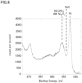
- the peak of nickel oxide (NiO) was not detected and the peaks of nickel hydroxide (Ni(OH) 2 ) and nickel trioxide (Ni 2 O 3 ) were higher in the metal porous bodies No. 1 to No. 3 in Examples 1 to 3, as compared with the metal porous body No. A in Comparative Example 1.
- the peak of nickel oxide (NiO) was also seen in the metal porous body No. 4 in Example 4
- the peak height of nickel oxide (NiO) was lower and the area sizes of the peaks of nickel hydroxide (Ni(OH) 2 ) and nickel trioxide (Ni 2 O 3 ) were reversed in the metal porous body No. 4 in Example 4, as compared with the metal porous body No. A in Comparative Example 1.
- the peak derived from hydrogen detected at the temperature higher than the evaporation temperature of water was large as a result of the TDS analysis, and thus, an amount of nickel hydroxide (Ni(OH) 2 ) on the surface of the framework was considered to be large.
- the peak of nickel hydroxide (Ni(OH) 2 ) was slightly seen as a result of the XPS analysis. However, the ranking of the area size of the peak was the same as that of the metal porous body No. A.
- the result of the TDS analysis was such that the height of the peak derived from hydrogen detected at the temperature higher than the evaporation temperature of water was low, and thus, an amount of nickel hydroxide (Ni(OH) 2 ) on the surface of the framework was considered to be small.
- the metal porous body No. C in Comparative Example 3 was an example in which the drying temperature for the metal porous body No. 2 was set at 240°C.
- the oxygen detection depth was significantly deeper in the AES analysis, and as to the ranking of the area sizes of the peaks in the XPS, the area of the peak of nickel oxide (NiO) and the areas of the peaks of nickel hydroxide (Ni(OH) 2 ) and nickel trioxide (Ni 2 O 3 ) were larger than the area of the peak of nickel (Ni).
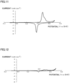
- Figs. 11 and 12 show an IV curve after the CV measurement of the metal porous body No. 1 in Example 1 and the metal porous body No. A in Comparative Example 1 is repeated 30 times.
- the horizontal axis represents a potential (V vs SHE) and the vertical axis represents a current (mA/cm 2 ).
- Example 1 a current value at a potential corresponding to charging and discharging of nickel hydroxide (Ni(OH) 2 ) is large, which suggests that a large amount of nickel hydroxide (Ni(OH) 2 ) is generated on the surface of the framework.
- a current value at the potential is very small, i.e., not more than 1/10 of that in Example 1, and thus, nickel hydroxide (Ni(OH) 2 ) is hardly generated.
- contact between the surface of the framework of the metal porous body and the active material is nickel/nickel hydroxide (surface of framework)/nickel hydroxide (active material), which is contact with nickel oxide (NiO) not being interposed.
Landscapes
- Chemical & Material Sciences (AREA)
- Engineering & Computer Science (AREA)
- Chemical Kinetics & Catalysis (AREA)
- Materials Engineering (AREA)
- General Chemical & Material Sciences (AREA)
- Electrochemistry (AREA)
- Metallurgy (AREA)
- Organic Chemistry (AREA)
- Mechanical Engineering (AREA)
- Manufacturing & Machinery (AREA)
- Composite Materials (AREA)
- Physics & Mathematics (AREA)
- Thermal Sciences (AREA)
- Crystallography & Structural Chemistry (AREA)
- Cell Electrode Carriers And Collectors (AREA)
Description
- The present invention relates to a metal porous body and a current collector for a nickel-metal hydride battery.
- Conventionally, a metal porous body has been used for various applications such as a filter and an electrode plate for a battery that require heat resistance, a catalyst carrier, and a composite metal material. A method for subjecting a surface of a base material such as foamed resin to conductive treatment and then plating the surface of the base material with metal, and a method for producing slurry of a powder metal, causing the slurry of the powder metal to adhere to a base material such as foamed resin and sintering the slurry of the powder metal have been traditionally known as a method for manufacturing a metal porous body.
- As a metal porous body fabricated by a plating method, there has been known, for example, Celmet (registered trademark: manufactured by Sumitomo Electric Industries, Ltd.) which is a metal porous body substantially made of nickel and obtained by subjecting a surface of a framework of a resin molded body having a framework of a three-dimensional network structure to conductive treatment and then plating the surface with nickel and then removing the resin. Celmet is a metal porous body having pores that communicate with each other, and has a characteristic of having a very high porosity (not less than 90%) as compared with other porous bodies such as metal non-woven fabric. Therefore, Celmet is suitably used as an electrode material for a battery such as a nickel-metal hydride battery or a nickel-cadmium battery.
- Various methods are under study as a method for manufacturing Celmet. For example,
Japanese Patent Laying-Open No. 2010-140647 Japanese Patent Laying-Open No. 2015-071804 US2016379764A1 relates to Ni(OH)2 nanoporous films as electrodes.JP2001202969A -
- PTL 1:
Japanese Patent Laying-Open No. 2010-140647 - PTL 2:
Japanese Patent Laying-Open No. 2015-071804 - The present invention provides a metal porous body according to claim 1.
- The present invention also provides a current collector for a nickel-metal hydride battery according to
claim 4. - The present invention also provides a current collector for a nickel-metal hydride battery according to claim 5.
-
-
Fig. 1 is an enlarged view schematically showing a partial cross section of an example metal porous body according to an embodiment of the present invention. -
Fig. 2 is an enlarged view schematically showing a partial cross section of an example state in which a conductive coating layer is formed on a surface of a framework of foamed urethane resin. -
Fig. 3 is a photograph as a substitute for a drawing of foamed urethane resin in an example resin molded body having a framework of a three-dimensional network structure. -
Fig. 4 is an enlarged view schematically showing a partial cross section of an example state in which a metal mainly composed of nickel is further formed on a surface of the conductive coating layer formed on the surface of the framework of the foamed urethane resin. -
Fig. 5 is a spectrum of a 1s orbital of O showing a result of analysis of a metal porous body No. 2 by XPS. -
Fig. 6 is a spectrum of the 1s orbital of O showing a result of analysis of a metal porous body No. 4 by the XPS. -
Fig. 7 is a spectrum of the 1s orbital of O showing a result of analysis of a metal porous body No. A by the XPS. -
Fig. 8 is a spectrum of three orbitals in 2p of Ni showing a result of analysis of the metal porous body No. 2 by the XPS. -
Fig. 9 is a spectrum of the three orbitals in 2p of Ni showing a result of analysis of the metal porous body No. 4 by the XPS. -
Fig. 10 is a spectrum of the three orbitals in 2p of Ni showing a result of analysis of the metal porous body No. A by the XPS. -
Fig. 11 is a graph showing a result of cyclic voltammetry measurement of a metal porous body No. 1. -
Fig. 12 is a graph showing a result of cyclic voltammetry measurement of the metal porous body No. A. - Each of the metal porous bodies obtained by the methods described in PTL 1 and
PTL 2 can be preferably used as a current collector for a nickel-metal hydride battery or the like. In recent years, smaller size and higher output of a battery used as a power supply of an electric vehicle or a hybrid vehicle have been requested, and thus, higher quality and further improvement of a manufacturing method have also been requested in a metal porous body so as to contribute to increase in battery performance. - Therefore, the present inventors have conducted earnest researches in order to provide a metal porous body that contributes to increase in battery performance, and have focused attention on the following point. Specifically, a surface of a framework of a metal porous body is generally covered with an oxide film, which results in relatively high contact resistance between an active material filled into a pore portion and the framework and becomes a factor for internal resistance of a battery.
- The present invention has been made in light of the above-described problem and an object of the present invention is to provide a metal porous body having a framework of a three-dimensional network structure that can reduce contact resistance between a surface of the framework of the metal porous body and an active material when the metal porous body is used as a positive electrode current collector for a battery.
- According to the foregoing, it is possible to provide a metal porous body having a framework of a three-dimensional network structure that can reduce contact resistance between a surface of the framework of the metal porous body and an active material when the metal porous body is used as a positive electrode current collector for a battery.
- First, embodiments of the present invention will be listed hereinafter.
- A metal porous body according to the present invention is according to claim 1.
- According to the metal porous body described in claim 1, it is possible to provide a metal porous body having a framework of a three-dimensional network structure that can reduce contact resistance between a surface of the framework of the metal porous body and an active material when the metal porous body is used as a positive electrode current collector for a battery.
- It is preferable that a content of NiO is lower than a content of Ni in the surface.
- Accordingly, an amount of NiO present in the surface of the framework is small, and thus, it is possible to provide a metal porous body having low contact resistance between a surface of a framework and an active material when the metal porous body is used as a positive electrode current collector for a battery.
- A content of a total of Ni2O3 and Ni(OH)2 is higher than a content of NiO in the surface.
- Accordingly, an amount of NiO present in the surface of the framework is small, and thus, it is possible to provide a metal porous body having low contact resistance between a surface of a framework and an active material when the metal porous body is used as a positive electrode current collector for a battery.
- The oxygen is detected by analyzing the surface in a depth direction of the framework using Auger electron spectroscopy (AES).
- Accordingly, it is possible to provide a metal porous body having low contact resistance between a surface of a framework and an active material when the metal porous body is used as a positive electrode current collector for a battery.
- Ni, NiO, Ni2O3, and Ni(OH)2 are detected by analyzing the surface using X-ray photoelectron spectroscopy (XPS).
- Accordingly, it is possible to provide a metal porous body having low contact resistance between a surface of a framework and an active material when the metal porous body is used as a positive electrode current collector for a battery.
- It is preferable that a peak of the NiO is absent in a spectrum of a 1s orbital of O, and area sizes of peaks of the Ni, the NiO, the Ni2O3, and the Ni(OH)2 satisfy a relational equation of Ni > a total of Ni2O3 and Ni(OH)2 > NiO in a spectrum of three orbitals in 2p of the Ni. As a result, contact resistance between a surface of a framework and an active material can be further reduced when the metal porous body is used as a positive electrode current collector for a battery.
- The hydrogen is detected as water desorbed from the metal porous body at a temperature higher than an evaporation temperature of water adsorbed on the surface, by analyzing the surface using thermal desorption spectrometry (TDS).
- Accordingly, it is possible to provide a metal porous body having low contact resistance between a surface of a framework and an active material when the metal porous body is used as a positive electrode current collector for a battery.
- In a reference example, the Ni(OH)2 is detected as a binding energy-derived peak corresponding to the Ni(OH)2 by analyzing the surface using X-ray photoelectron spectroscopy (XPS), and the hydrogen is detected as water desorbed from the metal porous body at a temperature higher than an evaporation temperature of water adsorbed on the surface, by analyzing the surface using thermal desorption spectrometry (TDS).
- According to this reference example, it is possible to provide a metal porous body having low contact resistance between a surface of a framework and an active material when the metal porous body is used as a positive electrode current collector for a battery.
- A current collector for a nickel-metal hydride battery according to an embodiment of the present invention is according to
claim 4. - According to the current collector of
claim 4, it is possible to provide a current collector for a nickel-metal hydride battery that can reduce contact resistance between the current collector and an active material. - current collector for a nickel-metal hydride battery according to an embodiment of the present invention is according to claim 5.
- According to the current collector of claim 5, it is possible to provide a current collector for a nickel-metal hydride battery that can reduce contact resistance between the current collector and an active material.
- A specific example of a metal porous body according to an embodiment of the present invention (hereinafter, also referred to as "the present embodiment") will be described below. The present invention is not limited to the description but is defined by the terms of the claims.
- The notation "A to B" in this specification means upper and lower limits of the range (i.e., not less than A and not more than B), and in the case where not A but only B is expressed in units, the unit of A is the same as that of B.
- A metal porous body according to an embodiment of the present invention is according to claim 1 and is a metal porous body mainly composed of nickel and having a framework of a three-dimensional network structure. "Nickel" described above refers to metal nickel. "Mainly composed of nickel" means that a content of nickel in the framework of the metal porous body is not less than 50% by mass. As components other than nickel, the metal porous body may intentionally or unavoidably include, for example, silicon, magnesium, carbon, tin, aluminum, iron, tungsten, titanium, cobalt, phosphorus, boron, silver, gold and the like, as long as the effect of the present invention is not impaired.
- The content of nickel in the framework of the metal porous body is preferably not less than 80% by mass, more preferably not less than 90% by mass, and further preferably not less than 95% by mass. As the content of nickel becomes higher, the corrosion resistance to an electrolyte, the electrochemical property and the mechanical property are improved.
-
Fig. 1 is an enlarged schematic view showing an enlarged cross section of an example metal porous body according to an embodiment of the present invention. As shown inFig. 1 , aframework 12 of a metalporous body 10 is formed of ametal 11 mainly composed of nickel. An interior 13 offramework 12 is hollow. Metalporous body 10 has pores that communicate with each other, and apore portion 14 is formed byframework 12. - In the metal porous body according to an embodiment of the present invention, Ni(OH)2 is present in a surface of the framework. Specifically, Ni(OH)2 is present in at least a surface (hereinafter, simply referred to as "surface of the framework") of a plane opposite to
interior 13 offramework 12, i.e., a plane that is in contact withpore portion 14. Ni(OH)2 present in the surface offramework 12 can be detected and quantified by analyzing the surface offramework 12 of metalporous body 10 using X-ray photoelectron spectroscopy (XPS). The analysis by the XPS may be performed using an X-ray photoelectron spectrometer. The analysis by the XPS may be performed at least on the metal porous body before or after being subjected to cyclic voltammetry (CV) measurement described below. - In the metal porous body according to an embodiment of the present invention, Ni(OH)2 may be present in a surface of a plane that is in contact with
interior 13 offramework 12. - Ni(OH)2 described above is detected as a binding energy-derived peak corresponding to Ni(OH)2 or Ni2O3 by analyzing the surface of
framework 12 of metalporous body 10 using the XPS. Furthermore, when the cyclic voltammetry (CV) measurement described below is performed, hydrogen may be detected as water desorbed from metalporous body 10 at a temperature higher than an evaporation temperature of water adsorbed on the surface offramework 12, by analyzing the surface offramework 12 of metalporous body 10 using thermal desorption spectrometry (TDS). The analysis by the TDS may be performed using a thermal desorption spectrometer. - In the metal porous body according to an embodiment of the present invention, when the cyclic voltammetry (CV) measurement is performed under the following measurement conditions, at least oxygen is detected within a depth of 5 nm from the surface of the framework, and preferably within a depth of 30 nm from the surface of the framework, and hydrogen is detected at least in the surface of the framework. "At least oxygen is detected within a depth of 5 nm from the surface of the framework" herein means that oxygen is invariably detected at any position within the depth of 5 nm from the surface of the framework (i.e., a depth of 0 nm). Furthermore, this means that oxygen may or may not be detected at a position exceeding the depth of 5 nm from the surface of the framework. Specifically, oxygen is detected by element analysis using Auger electron spectroscopy (AES) described below.
- The metal porous body is subjected to at least 30 potential scans between a lower limit potential of -0.10 V and an upper limit potential of +0.65 V with respect to a hydrogen standard potential in not less than 10% by mass and not more than 35% by mass of a potassium hydroxide aqueous solution.
- The above-described oxygen detected in a depth direction from the surface of
framework 12 of metalporous body 10 subjected to the CV measurement is detected by analyzing the surface offramework 12 of metalporous body 10 in the depth direction offramework 12 using the Auger electron spectroscopy (AES). The analysis by the AES may be performed using a scanning Auger electron spectrometer. - The above-described hydrogen detected in the surface of
framework 12 of metalporous body 10 subjected to the CV measurement is detected as water desorbed from metalporous body 10 at a temperature higher than an evaporation temperature of water adsorbed on the surface offramework 12, by analyzing the surface offramework 12 of metalporous body 10 using the thermal desorption spectrometry (TDS). The analysis by the TDS may be performed using the thermal desorption spectrometer. Specifically, the above-described hydrogen is detected as hydrogen (element) in a water molecule desorbed from metalporous body 10 at a temperature higher than an evaporation temperature of water in the TDS. - In the metal porous body according to an embodiment of the present invention, Ni(OH)2 is present in the surface of the framework, and thus, a content of NiO in the surface of the framework is lower than that of a conventional metal porous body. When the metal porous body is used as a current collector for a battery, NiO present in the surface of the framework becomes a cause of contact resistance between the metal porous body and an active material. Therefore, when the metal porous body according to an embodiment of the present invention in which the content of NiO in the surface of the framework is low is used as a current collector, a battery having low internal resistance can be provided.
- Furthermore, in the case of performing the above-described CV measurement in which a load similar to a load in use as a nickel-metal hydride battery is applied, hydrogen derived from a substance other than water can also be detected using the XPS and the TDS because Ni(OH)2 is present in the surface of the framework of the metal porous body. After the CV measurement, oxygen can be detected at a deeper position in the depth direction from the surface of the framework of the metal porous body.
- In the metal porous body according to an embodiment of the present invention, the content of NiO is preferably lower than a content of Ni in the surface of
framework 12. By making the content of NiO lower than the content of Ni in the surface offramework 12, the contact resistance between the surface offramework 12 of the metal porous body and the active material can be further reduced when the metal porous body is used as a current collector for a battery. - Ni and NiO present in the surface of
framework 12 of metalporous body 10 can be detected and quantified by analyzing the surface offramework 12 of metalporous body 10 using the XPS. The analysis by the XPS may be performed under the same conditions as those described above. - In addition to Ni, NiO and Ni(OH)2, Ni2O3 may be present in the surface of
framework 12 of metalporous body 10. Ni2O3 present in the surface offramework 12 of metalporous body 10 can be detected and quantified by analyzing the surface offramework 12 of metalporous body 10 using the XPS. The analysis by the XPS may be performed under the same conditions as those described above. - In the surface of the framework of the metal porous body according to an embodiment of the present invention, a content of a total of Ni2O3 and Ni(OH)2 is higher than the content of NiO. As a result, when the metal porous body is used as a positive electrode current collector for a battery in which Ni(OH)2 is used as an active material, the contact resistance between the surface of the framework of the metal porous body and the active material can be reduced and the internal resistance of the battery can be reduced.
- The content of the total of Ni2O3 and Ni(OH)2 being higher than the content of NiO in the surface of the framework of the metal porous body can be confirmed based on, for example, an area of a peak of the total of Ni2O3 and Ni(OH)2 being detected to be larger than an area of a peak of NiO when the surface of the framework of the metal porous body is analyzed using the XPS.
- In the surface of the framework of the metal porous body according to the embodiment of the present invention, the content of NiO is preferably lower than the content of Ni. In the surface of the framework of the metal porous body, the content of NiO isy lower than the content of the total of Ni2O3 and Ni(OH)2.
- By making the content of NiO lower than the content of Ni or the content of the total of Ni2O3 and Ni(OH)2 in the surface of the framework of the metal porous body, a battery reaction can be promoted and the internal resistance of the battery can be reduced when the metal porous body is used as a positive electrode current collector for a battery in which Ni(OH)2 is used as an active material.
- As described above, comparison among the content of NiO, the content of Ni and the content of the total of Ni2O3 and Ni(OH)2 in the surface of the framework of the metal porous body can be performed by comparing area sizes of the respective peaks when the surface of the framework of the metal porous body is analyzed using the XPS. That is, it is preferable that when the surface of the framework of the metal porous body according to an embodiment of the present invention is analyzed using the XPS, the peak of NiO is absent in a spectrum of a 1s orbital of O, and the area sizes of the peaks of Ni, NiO, Ni2O3, and Ni(OH)2 satisfy a relational equation of Ni > the total of Ni2O3 and Ni(OH)2 > NiO in a spectrum of three orbitals in 2p of Ni. In the XPS analysis, the peaks of Ni2O3 and Ni(OH)2 in the three orbitals in 2p of Ni are detected at positions of binding energy close to each other. The area of each peak can be calculated by peak fitting. "Three orbitals in 2p of Ni" described above refer to three (px, py and pz) orbitals in a p orbital (2p) of Ni.
- A content of hydrogen in the surface of the framework of the metal porous body according to the embodiment of the present invention is preferably higher than a content of hydrogen in a surface of a framework of a conventional nickel porous body. As a result, when the metal porous body is used as a positive electrode current collector for a battery in which Ni(OH)2 is used as an active material, the contact resistance between the surface of the framework of the metal porous body and the active material can be reduced and the internal resistance of the battery can be reduced. However, the metal porous body is the same as the conventional nickel porous body in terms of average pore diameter, porosity, metal apparent weight, and thickness.
- Comparison of the content of hydrogen in the surface of the framework can be performed, for example, by analyzing the surface of the framework of the metal porous body and the surface of the framework of the conventional nickel porous body using the TDS.
- In the metal porous body according to an embodiment of the present invention, oxygen is detected within a depth of 5 nm from the surface of the framework, and preferably within a depth of 30 nm from the surface of the framework, and hydrogen is detected at least in the surface of the framework. As a result, when the metal porous body is used as a positive electrode current collector for a battery in which Ni(OH)2 is used as an active material, the battery reaction can be promoted and the internal resistance of the battery can be reduced.
- How far in the depth direction oxygen is present from the surface of the framework of the metal porous body can be confirmed by analyzing the framework of the metal porous body using the AES as described above. The presence of hydrogen in the surface of the framework of the metal porous body can be confirmed by the TDS analysis.
- The apparent weight of the metal porous body according to an embodiment of the present invention is not particularly limited, and is preferably not less than 150 g/m2 and not more than 500 g/m2. When the apparent weight of the metal porous body is not less than 150 g/m2, the strength of the metal porous body can be kept, and further, the metal porous body can offer sufficient current collection performance when the metal porous body is used as a current collector for a battery. When the apparent weight of the metal porous body is not more than 500 g/m2, a unit mass is not increased excessively and further a sufficient amount of active material can be filled into the pore portion when the metal porous body is used as a current collector for a battery. From these perspectives, the apparent weight of the metal porous body is more preferably not less than 200 g/m2 and not more than 450 g/m2.
- The apparent weight of the metal porous body refers to an apparent mass per unit area of the main surface of the metal porous body.
- The metal porous body according to an embodiment of the present invention preferably has a thickness of not less than 0.5 mm and not more than 2.0 mm. When the metal porous body has a thickness of not less than 0.5 mm, the active material can be easily filled, and further, the number of frameworks of the metal porous body can be increased and the metal porous body can offer sufficient current collection performance. When the metal porous body has a thickness of not more than 2.0 mm, an amount of deformation during compression of the electrode can be reduced and an increase in resistance can be inhibited. From these perspectives, the thickness of the metal porous body is more preferably not less than 0.7 mm and not more than 1.5 mm.
- When the metal porous body according to an embodiment of the present invention is used as an electrode for a battery, a thickness of the electrode is preferably not less than 0.1 mm and not more than 2.0 mm, and more preferably not less than 0.3 mm and not more than 1.0 mm, after the active material is filled into the pore portion of the metal porous body. The thicknesses of the metal porous body and the electrode can be adjusted, for example, by a roll press and the like.
- The metal porous body according to an embodiment of the present invention has an average pore diameter of not less than 250 µm and not more than 500 µm. When the metal porous body has an average pore diameter of not less than 250 µm, the active material can be easily filled and a sufficient amount of active material can be filled into the pore portion. When the metal porous body has an average pore diameter of not more than 500 µm, a surface area of the metal porous body can be increased and the metal porous body can offer sufficient current collection performance. From these perspectives, the average pore diameter of the metal porous body is preferably not less than 300 µm and not more than 400 µm.
- The average pore diameter of the metal porous body refers to an average pore diameter calculated as average pore diameter = 25.4 mm/the number of cells by observing the surface of the metal porous body with a microscope or the like, and counting the number of pores per inch (25.4 mm) as the number of cells.
- The metal porous body according to an embodiment of the present invention preferably has a porosity of not less than 80% and not more than 98%. When the porosity is not less than 80%, the active material can be easily filled and a sufficient amount of active material can be filled into the pore portion. When the porosity is not more than 98%, the strength of the metal porous body can be kept, and further, the metal porous body can offer sufficient current collection performance when the metal porous body is used as a current collector for a battery. From these perspectives, the porosity of the metal porous body is more preferably not less than 90% and not more than 96%.
- The porosity of the metal porous body is defined in accordance with the following equation:
porosity = (1-(mass [g] of porous material/(volume [cm3] of porous material×material density [g/cm3]))×100 [%]. - The above-described material density refers to a density calculated by multiplying a theoretical density of each component forming the metal porous body by the content of each component described above.
- A current collector according to an embodiment of the present invention is a current collector for a nickel-metal hydride battery including the above-described metal porous body according to an embodiment of the present invention.
- The current collector refers to a battery material that is responsible for maintaining electrical connection with the active material in the electrode of the battery, collecting electrons that move with a charging and discharging reaction, and extracting the electrons to the outside of the battery as a current. By causing the current collector to carry the active material, the current collector can function as an electrode.
- The current collector for a nickel-metal hydride battery according to an embodiment of the present invention is according to claim 5.
- The nickel-metal hydride battery according to an embodiment of the present invention (not claimed) is a nickel-metal hydride battery including a positive electrode formed by filling an active material mainly composed of Ni(OH)2 into a positive electrode current collector, a negative electrode including a hydrogen-storing alloy, a separator, and an electrolyte. The metal porous body according to an embodiment of the present invention is used as the positive electrode current collector.
- A configuration of the nickel-metal hydride battery is not particularly limited as long as the metal porous body according to an embodiment of the present invention is used as the positive electrode current collector, and a configuration of a conventional nickel-metal hydride battery can be suitably used. For example, a cylindrical battery may be fabricated by interposing a separator between a positive electrode and a negative electrode to thereby obtain an electrode group, winding the electrode group to have a spiral shape, and inserting the spiral electrode group into an electrolyzer, into which an electrolyte is injected. A rectangular battery may be fabricated by stacking a positive electrode and a negative electrode with a separator being interposed, to thereby obtain an electrode group having a stacked structure, and inserting the electrode group into an electrolyzer, into which an electrolyte is injected.
- A positive electrode formed by filling an active material mainly composed of nickel hydroxide into the pore portion of the metal porous body according to an embodiment of the present invention may be used as the positive electrode.
- The above-described metal porous body according to an embodiment of the present invention can be manufactured in accordance with the following method, for example.
- Specifically, in a method for manufacturing a metal porous body having:
- a conductive treatment step of subjecting a surface of a framework of a resin molded body having a framework of a three-dimensional network structure to conductive treatment;
- a resin structure formation step of plating the surface of the framework of the resin molded body subjected to conductive treatment with nickel, to thereby form a resin structure;
- a first heat treatment step of subjecting the resin structure to heat treatment under oxidizing atmosphere and burning and removing a resin, to thereby form an oxidized metal porous body; and
- a second heat treatment step of subjecting the oxidized metal porous body to heat treatment under reducing atmosphere, to thereby reduce a metal,
- the metal porous body according to an embodiment of the present invention can be manufactured, for example, by further subjecting the metal porous body to treatment after the second heat treatment step as in a first method or a second method described below.
- The first method is a method for surface-treating the metal porous body subjected to the second heat treatment step with acid, and then, washing the metal porous body with water and drying the metal porous body.
- The acid used in the first method is not particularly limited, and hydrochloric acid, sulfuric acid, nitric acid, a mixture thereof or the like is preferably used. As a result, the surface of the framework of the metal porous body can be efficiently treated and it is possible to obtain the metal porous body in which a content of NiO is lower than a content of a total of Ni2O3 and Ni(OH)2 in the surface of the framework. A method for treatment with the acid is not particularly limited, and a method for immersing the metal porous body in the acid may, for example, be used. When the time of treatment with the acid is too short, the treatment is insufficient. In contrast, when the time of treatment with the acid is too long, the strength of the metal porous body decreases. Therefore, the time of treatment with the acid is preferably not shorter than 5 seconds and not longer than 15 minutes, and more preferably not shorter than 10 seconds and not longer than 10 minutes.
- After the acid treatment, the metal porous body is washed with water to remove the acid, and dried. When the drying temperature is too high, NiO is formed due to dehydration of Ni(OH)2. Therefore, the metal porous body is preferably dried at a temperature of not higher than 200°C. When the drying temperature is too low, drying requires time, which may cause a poor appearance such as discoloration of the metal porous body. Therefore, the metal porous body is preferably dried at a temperature of not lower than 35°C. The more preferable drying temperature is not lower than 40°C and not higher than 150°C. The drying time is not particularly limited and may be selected as appropriate in accordance with the drying temperature. In order to speed up drying, a method for removing a liquid droplet using a blower or the like is preferably used, for example.
- The second method is a method for immersing the metal porous body subjected to the second heat treatment step in water for a certain time period, and then, drying the metal porous body at a temperature of not higher than 100°C.
- This method is a method for making a content of NiO lower than a content of a total of Ni2O3 and Ni(OH)2 by modifying the surface of the framework of the metal porous body subjected to the second heat treatment step.
- The time of immersion of the metal porous body in water is not particularly limited. However, when the time of immersion is too short, the treatment is insufficient. For example, the time of immersion may be not shorter than 3 hours and not longer than 24 hours, more preferably not shorter than 5 hours and not longer than 20 hours, and further preferably not shorter than 6 hours and not longer than 12 hours.
- When the drying temperature is too high, NiO is formed due to dehydration of Ni(OH)2. Therefore, the drying temperature is preferably not higher than 200°C. When the drying temperature is too low, drying requires time, which causes a poor appearance such as discoloration. Therefore, the drying temperature is preferably not lower than 35°C. The drying temperature is more preferably not lower than 40°C and not higher than 150°C. The drying time is not particularly limited and may be selected as appropriate in accordance with the drying temperature. In order to speed up drying, a method for removing a liquid droplet using a blower or the like is preferably used.
- Each step of the above-described method for manufacturing the metal porous body according to an embodiment of the present invention will be described in detail below.
- This step is a step of preparing a resin molded
body 15 having a framework of a three-dimensional network structure, and subjecting a surface of the framework of resin moldedbody 15 to conductive treatment, to thereby form aconductive coating layer 16, as shown inFig. 2 . - A resin foam, non-woven fabric, felt, woven fabric or the like is used as resin molded
body 15 having the framework of the three-dimensional network structure used when the metal porous body according to an embodiment of the present invention is manufactured, and these can also be used in combination as needed. Although a material is not particularly limited, a material that can be removed by incineration after being plated with metal is preferable. From the perspective of handling of resin moldedbody 15, resin moldedbody 15 is preferably made of a flexible material because high stiffness leads to fracture particularly in the case of sheet-like resin moldedbody 15. - A resin foam is preferably used as resin molded
body 15 having the framework of the three-dimensional network structure. A known or commercially available resin foam can be used as long as the resin foam is porous, and examples of the resin foam include foamed urethane, styrofoam and the like. Among these, foamed urethane is preferable, particularly from the perspective of a high porosity.Fig. 3 shows a photograph of foamed urethane resin. - A porosity of resin molded
body 15 may be, for example, not less than 80% and not more than 98%, and more preferably not less than 90% and not more than 96%. A thickness of resin moldedbody 15 is not limited, either, and may be usually, for example, not less than 0.5 mm and not more than 2.0 mm, and preferably not less than 0.7 mm and not more than 1.5 mm. An average pore diameter of resin moldedbody 15 is not limited and can be set as appropriate in accordance with an application. - A method for conductive treatment is not particularly limited as long as
conductive coating layer 16 can be provided on the surface of the framework of resin moldedbody 15. Examples of a material ofconductive coating layer 16 include amorphous carbon such as carbon black, and carbon powder such as graphite, in addition to metal such as nickel, titanium or stainless steel. Among these, the carbon powder is particularly preferable. When the amorphous carbon or the like other than the metal is used,conductive coating layer 16 is also removed in resin molded body removal treatment described below. - Specific examples of the conductive treatment preferably include electroless plating treatment, sputtering treatment and the like when nickel is used, for example. When the materials including metal such as titanium or stainless steel, carbon black, and graphite are used, examples of a preferable method include treatment for coating the surface of the framework of resin molded
body 15 with a mixture obtained by adding a binder to a fine powder of these materials. - As the electroless plating treatment using nickel, resin molded
body 15 may, for example, be immersed in a known electroless nickel plating bath such as a nickel sulfate aqueous solution containing sodium hypophosphite as a reducing agent. As needed, resin moldedbody 15 may be immersed in an activating solution (cleaning solution manufactured by Kanigen Co., Ltd.) including a very small amount of a palladium ion, before being immersed in the plating bath. - As the sputtering treatment using nickel, blown-off nickel particles may be deposited on the surface of the framework of resin molded
body 15 by mounting resin moldedbody 15 on a substrate holder, and then, applying a DC voltage between the holder and the target (nickel) while introducing an inert gas, to thereby bring the ionized inert gas into collision with nickel. -
Conductive coating layer 16 may be formed continuously on the surface of the framework of resin moldedbody 15. An apparent weight ofconductive coating layer 16 is not limited, and may be usually not less than 5 g/m2 and not more than 15 g/m2, and preferably not less than 7 g/m2 and not more than 10 g/m2. - This step is a step of plating, with nickel, resin molded
body 15 whose surface of the framework became conductive through the conductive treatment step, to thereby stack an electroplated layer, i.e., ametal 11 mainly composed of nickel. - When a thickness of a plating film is increased by both or one of the above-described electroless plating treatment and sputtering treatment, electroplating treatment is not particularly needed. However, from the perspectives of productivity and cost, a method for first subjecting resin molded
body 15 to conductive treatment by the above-described method, and then, forming an electroplated layer of nickel by an electroplating method is preferably used. - The electroplating treatment may be performed in accordance with an ordinary method. For example, a known or commercially available bath can be used as the nickel plating bath, and examples of the nickel plating bath include a watt bath, a chloride bath, a sulfamic acid bath and the like. An electroplated coating can further be formed on
conductive coating layer 16 by immersing resin moldedbody 15 havingconductive coating layer 16 formed on the surface by electroless plating, sputtering or the like described above in the plating bath, and connecting resin moldedbody 15 to a negative electrode and a counter electrode plate of the plated metal to a positive electrode to apply a DC or pulse intermittent current. - The electroplated layer may be formed on
conductive coating layer 16 to such an extent thatconductive coating layer 16 is not exposed. An apparent weight of the electroplated layer is not limited, and may be usually not less than 150 g/m2 and not more than 500 g/m2, and more preferably not less than 200 g/m2 and not more than 450 g/m2. A total amount ofconductive coating layer 16 and the electroplated layer described above is preferably not less than 200 g/m2 and not more than 500 g/m2. When the total amount ofconductive coating layer 16 and the electroplated layer is not less than 200 g/m2, the strength of the metal porous body can be kept excellently. When the total amount ofconductive coating layer 16 and the electroplated layer is not more than 500 g/m2, the metal porous body can be manufactured advantageously in terms of cost. - This step is a step of subjecting the resin structure obtained above to heat treatment, to thereby remove resin molded
body 15 used as a base material and leave only the electroplated layer. - Specifically, resin molded
body 15 may be burned and removed by subjecting the resin structure to heat treatment under oxidizing atmosphere such as the air having a temperature of not lower than 600°C and not higher than 800°C, and preferably not lower than 600°C and not higher than 700°C. - This step is a step of reducing the oxidized metal porous body obtained by the first heat treatment step.
- A hydrogen gas or a gas mainly composed of a mixed gas of a hydrogen gas and an inert gas is used as a reducing gas as needed, with a composition being changed. "Mainly composed of the mixed gas" means that a ratio of the hydrogen gas or the mixed gas of the hydrogen gas and the inert gas to the reducing gas is not less than 50% by volume.
- By adding the inert gas as the reducing gas, the efficiency of the redox property is increased. N2, argon, helium and the like can be preferably used as the inert gas. A forming gas, which is a mixed gas of H2 and N2 obtained by using an ammonia gas as a raw material gas and decomposing the ammonia gas, may be used as the reducing gas.
- The second heat treatment step may be performed at a temperature of not lower than 900°C. From the perspectives of being disadvantage in terms of cost and a material of a furnace body of a reducing furnace, the second heat treatment step may be performed at a temperature of not higher than 1000°C.
- By further applying the above-described first method or second method subsequently to the above-described steps, the metal porous body according to an embodiment of the present invention can be obtained.
- While the present invention will be described in more detail below based on Examples, these Examples are provided by way of example and the metal porous body according to the present invention is not limited thereto. The scope of the present invention is defined by the terms of the claims.
- A polyurethane sheet having a thickness of 1.5 mm was used as a resin molded body having a framework of a three-dimensional network structure. The resin molded body had a porosity of 96% and an average pore diameter of 450 µm.
- 100 g of carbon black, which was amorphous carbon having a particle size of 0.01 to 0.2 µm, was dispersed in 0.5 L of a 10% acrylic ester-based resin aqueous solution, to thereby fabricate an adhesive paint at this ratio.
- Next, the resin molded body was continuously immersed in the above-described adhesive paint, squeezed with a roller and then dried, to thereby form a conductive coating layer on a surface of the framework of the resin molded body. The resin molded body was thus subjected to conductive treatment.
- 500 g/m2 of nickel was applied onto the surface of the framework of the resin molded body subjected to conductive treatment by electroplating, to thereby fabricate a resin structure having an electroplated layer on the surface of the framework.
- Next, in order to remove a resin component from the resin molded body having the conductive coating layer and the electroplated layer obtained above, a first heat treatment step of heating under atmospheric oxidizing atmosphere at 700°C was performed.
- Next, the reducing atmosphere formed of a reducing gas including a mixed gas of H2 and N2 (forming gas) at 1000°C was formed in a heat treatment chamber where a second heat treatment step was performed, and the above-described metal porous body was introduced into the heat treatment chamber where the second heat treatment step was performed. As a result, nickel was reduced and annealed, to thereby obtain a sheet-like metal porous body.
- The obtained metal porous body was immersed for 5 seconds in acid obtained by mixing 60% nitric acid and 35% hydrochloric acid at a volume ratio of 5:1, and then, was washed with water. Thereafter, the metal porous body was dried for 30 minutes in a hot-air high-temperature bath having a temperature of 45°C, to thereby obtain a metal porous body No. 1.
- A metal porous body No. 2 was fabricated similarly to Example 1, except that the time of immersion of the metal porous body in the acid was set at 10 seconds in Example 1.
- A metal porous body No. 3 was fabricated similarly to Example 1, except that the time of immersion of the metal porous body in the acid was set at 10 minutes in Example 1.
- A metal porous body No. 4 was manufactured similarly to Example 2, except that the acid obtained by mixing 60% nitric acid and 35% hydrochloric acid at the volume ratio of 5:1 was changed to 30% sulfuric acid in Example 2.
- A metal porous body No. A was fabricated similarly to Example 1, except that the metal porous body was not subjected to acid treatment in Example 1.
- A metal porous body No. B was fabricated similarly to Example 1, except that the time of immersion of the metal porous body in the acid was set at 1 second in Example 1.
- A metal porous body No. C was fabricated similarly to Example 2, except that the metal porous body was immersed in the acid and washed with water, and then, dried for 60 minutes in the hot-air high-temperature bath having a temperature of 240°C in Example 2.
- The surfaces of the frameworks of metal porous bodies No. 1 to No. 4 and metal porous bodies No. A to No. C obtained as described above were analyzed as follows.
- In not less than 10% by mass and not more than 35% by mass of a potassium hydroxide aqueous solution, each metal porous body was subjected to 30 potential scans between a lower limit potential of -0.10 V and an upper limit potential of +0.65 V with respect to a hydrogen standard potential.
- The surface of the framework of each metal porous body after CV measurement was subjected to element analysis in a depth direction using the AES, to thereby check a depth at which oxygen was detected. The AES analysis was performed under the following conditions, using the scanning Auger electron spectrometer ("PHI700" manufactured by ULVAC PHI).
- Electron beam: 10 kV, 10 nA
- Sample inclination: 30°
- Sputter: 1kV
- The surface of the framework of each metal porous body before CV measurement was analyzed using the XPS, to thereby check a behavior of a peak in a 1s orbital of O and a behavior of a peak in three orbitals in 2p of Ni. The XPS analysis was performed under the following conditions, using "QuanteraSXM" manufactured by ULVAC PHI.
- X-ray condition: beam diameter 100 µm, 25 W, 15 kV
- Transmission energy: 55, 112 eV
- Charge neutralization: electron +Ar
- X-ray incident angle: 90°
- Photoelectron extraction angle: 45°
- The surface of the framework of each metal porous body after CV measurement was analyzed using the TDS, to thereby check whether or not a peak derived from hydrogen detected as water desorbed from the metal porous body at a temperature higher than an evaporation temperature of water, and a size of the above-described peak derived from hydrogen when the peak was detected. The TDS analysis was performed under the following conditions, using "TDS1200" manufactured by ESCO, Ltd.
- Heating temperature: 50°C to 1400°C (stage temperature)
- Temperature rising speed: 30°C/min (stage temperature control)
- Measured mass number range: M/z = 1 to 200 (measured in a fixed amount mode)
- Sample pretreatment: A sample cut into 10 mm×10 mm was used as a measurement sample.
- Results of the AES analysis, the XPS analysis and the TDS analysis described above are shown in Table 1. Furthermore, the metal porous body No. 2, the metal porous body No. 4 and the metal porous body No. A were analyzed by the XPS, and their spectra of the 1s orbital of O are shown in
Figs. 5 to 7 and their spectra of the three orbitals in 2p of Ni are shown inFigs. 8 to 10 . InFigs. 5 to 10 , the vertical axis represents an absorption intensity and a horizontal axis represents binding energy (eV).[Table 1] Metal porous body No. AES analysis XPS analysis TDS analysis Oxygen detection depth (nm) 1s orbital of O Three orbitals in 2p of Ni Detection of hydrogen Presence or absence of NiO peak Ranking of area size of Ni peak Ranking of area size of NiO peak Ranking of area size of total of NiOH2 and Ni2O3 peaks Amount of peak derived from hydrogen detected at temperature higher than evaporation temperature of water 1 6.0 absent 1 no peak 2 large 2 8.2 absent 1 no peak 2 large 3 15.0 absent 1 no peak 2 large 4 5.6 present 1 3 2 large A 4.3 present 1 2 3 small B 4.7 present 1 2 3 small C 31 present 3 1 2 none - According to the result of the XPS analysis (see
Figs. 5 to 10 ), the peak of nickel oxide (NiO) was not detected and the peaks of nickel hydroxide (Ni(OH)2) and nickel trioxide (Ni2O3) were higher in the metal porous bodies No. 1 to No. 3 in Examples 1 to 3, as compared with the metal porous body No. A in Comparative Example 1. Although the peak of nickel oxide (NiO) was also seen in the metal porous body No. 4 in Example 4, the peak height of nickel oxide (NiO) was lower and the area sizes of the peaks of nickel hydroxide (Ni(OH)2) and nickel trioxide (Ni2O3) were reversed in the metal porous body No. 4 in Example 4, as compared with the metal porous body No. A in Comparative Example 1. - In the metal porous bodies No. 1 to No. 4 in Examples 1 to 4, the peak derived from hydrogen detected at the temperature higher than the evaporation temperature of water was large as a result of the TDS analysis, and thus, an amount of nickel hydroxide (Ni(OH)2) on the surface of the framework was considered to be large.
- In the metal porous bodies No. 1 to No. 4 in Examples 1 to 4, at least oxygen was detected within a depth of 5 nm from the surface of the framework as a result of the AES analysis. In the metal porous body No. A in Comparative Example 1 and the metal porous body No. B in Comparative Example 2, oxygen was detected only within a depth of 4.3 nm and 4.7 nm from the surface of the framework, respectively.
- In the metal porous body No. B in Comparative Example 2, the peak of nickel hydroxide (Ni(OH)2) was slightly seen as a result of the XPS analysis. However, the ranking of the area size of the peak was the same as that of the metal porous body No. A. The result of the TDS analysis was such that the height of the peak derived from hydrogen detected at the temperature higher than the evaporation temperature of water was low, and thus, an amount of nickel hydroxide (Ni(OH)2) on the surface of the framework was considered to be small.
- The metal porous body No. C in Comparative Example 3 was an example in which the drying temperature for the metal porous body No. 2 was set at 240°C. However, the oxygen detection depth was significantly deeper in the AES analysis, and as to the ranking of the area sizes of the peaks in the XPS, the area of the peak of nickel oxide (NiO) and the areas of the peaks of nickel hydroxide (Ni(OH)2) and nickel trioxide (Ni2O3) were larger than the area of the peak of nickel (Ni). In the TDS analysis, there is no peak derived from hydrogen at the temperature higher than the evaporation temperature of water, and thus, nickel oxide (NiO) and nickel trioxide (Ni2O3), not nickel hydroxide (Ni(OH)2), were considered to be present on the surface of the metal porous body No. C.
-
Figs. 11 and 12 show an IV curve after the CV measurement of the metal porous body No. 1 in Example 1 and the metal porous body No. A in Comparative Example 1 is repeated 30 times. InFigs. 11 and 12 , the horizontal axis represents a potential (V vs SHE) and the vertical axis represents a current (mA/cm2). - In Example 1, a current value at a potential corresponding to charging and discharging of nickel hydroxide (Ni(OH)2) is large, which suggests that a large amount of nickel hydroxide (Ni(OH)2) is generated on the surface of the framework. In contrast, in Comparative Example 1, a current value at the potential is very small, i.e., not more than 1/10 of that in Example 1, and thus, nickel hydroxide (Ni(OH)2) is hardly generated. Based on this, when a conventional metal porous body having a surface of a framework covered with an oxide film as in Comparative Example 1 is used as a current collector for a nickel-metal hydride battery, contact between the surface of the framework of the metal porous body and the active material is nickel (surface of framework)/nickel oxide/nickel hydroxide (active material), which is contact with the nickel oxide (NiO) film being interposed, and thus, resistance is considered to be high. In contrast, unlike Comparative Example 1, the surface of the framework of the metal porous body in Example 1 is covered with nickel hydroxide (Ni(OH)2). Therefore, contact between the surface of the framework of the metal porous body and the active material is nickel/nickel hydroxide (surface of framework)/nickel hydroxide (active material), which is contact with nickel oxide (NiO) not being interposed. Based on the foregoing, when the metal porous body according to an embodiment of the present invention is used as a current collector for a nickel-metal hydride battery, the contact resistance between the metal porous body and the active material can be significantly reduced and the internal resistance of the battery can be reduced.
- 10 metal porous body; 11 metal mainly composed of nickel; 12 framework; 13 interior of framework; 14 pore portion; 15 resin molded body; 16 conductive coating layer.
Claims (5)
- A metal porous body mainly composed of nickel and having a framework of a three-dimensional network structure,Ni(OH)2 being present in a surface of the framework,at least oxygen being invariably detected at any position within a depth of 5 nm from the surface, and hydrogen being detected at least in the surface, when the metal porous body is subjected to at least 30 potential scans between a lower limit potential of -0.10 V and an upper limit potential of +0.65 V with respect to a hydrogen standard potential in not less than 10% by mass and not more than 35% by mass of a potassium hydroxide aqueous solution, wherein the oxygen is detected by analyzing the surface in a depth direction of the framework using Auger electron spectroscopy (AES) according to the method described in the description and wherein the hydrogen is detected as water desorbed from the metal porous body at a temperature higher than an evaporation temperature of water adsorbed on the surface, by analyzing the surface using thermal desorption spectrometry (TDS) according to the method described in the description,the metal porous body having an average pore diameter of not less than 250 µm and not more than 500 µm, wherein the average pore diameter of the metal porous body is calculated as average pore diameter determined by dividing 25.4 mm by the number of cells, by observing the surface of the metal porous body with a microscope and counting the number of pores per 25.4 mm (inch) as the number of cells,Ni, NiO, Ni2O3, and Ni(OH)2 are detected by analyzing the surface using X-ray photoelectron spectroscopy (XPS) according to the method described in the description, anda content of a total of Ni2O3 and Ni(OH)2 is higher than a content of NiO in the surface, the relative contents determined by comparing area sizes of the respective peaks when the surface of the framework of the metal porous body is analyzed using XPS according to the method described in the description.
- The metal porous body according to claim 1, wherein
a content of NiO is lower than a content of Ni in the surface, the relative contents determined by comparing area sizes of the respective peaks when the surface of the framework of the metal porous body is analyzed using XPS according to the method described in the description. - The metal porous body according to claim 1 or 2, wherein
a peak of the NiO is absent in a spectrum of a 1s orbital of O, and area sizes of peaks of the Ni, the NiO, the Ni2O3, and the Ni(OH)2 satisfy a relational equation of Ni > a total of Ni2O3 and Ni(OH)2 > NiO in a spectrum of three orbitals in 2p of the Ni. - A current collector for a nickel-metal hydride battery including the metal porous body as recited in any one of claims 1 to 3.
- A current collector for a nickel-metal hydride battery including a metal porous body, the metal porous body being mainly composed of nickel and having a framework of a three-dimensional network structure,Ni(OH)2 being present in a surface of the framework,at least oxygen being invariably detected at any position within a depth of 5 nm from the surface, whereinthe metal porous body having an average pore diameter of not less than 250 µm and not more than 500 µm, wherein the average pore diameter of the metal porous body is calculated as average pore diameter determined by dividing 25.4 mm by the number of cells, by observing the surface of the metal porous body with a microscope and counting the number of pores per 25.4 mm (inch) as the number of cells,Ni, NiO, Ni2O3, and Ni(OH)2 are detected by analyzing the surface using X-ray photoelectron spectroscopy (XPS) according to the method described in the description, anda content of a total of Ni2O3 and Ni(OH)2 is higher than a content of NiO in the surface, the relative contents determined by comparing area sizes of the respective peaks when the surface of the framework of the metal porous body is analyzed using XPS according to the method described in the description.
Applications Claiming Priority (2)
| Application Number | Priority Date | Filing Date | Title |
|---|---|---|---|
| JP2017139115 | 2017-07-18 | ||
| PCT/JP2018/026137 WO2019017252A1 (en) | 2017-07-18 | 2018-07-11 | Porous metal body and current collector for nickel metal-hydride battery |
Publications (3)
| Publication Number | Publication Date |
|---|---|
| EP3656882A1 EP3656882A1 (en) | 2020-05-27 |
| EP3656882A4 EP3656882A4 (en) | 2021-03-24 |
| EP3656882B1 true EP3656882B1 (en) | 2025-03-12 |
Family
ID=65015950
Family Applications (1)
| Application Number | Title | Priority Date | Filing Date |
|---|---|---|---|
| EP18834902.1A Active EP3656882B1 (en) | 2017-07-18 | 2018-07-11 | Porous metal body and current collector for nickel metal-hydride battery |
Country Status (5)
| Country | Link |
|---|---|
| US (1) | US11271215B2 (en) |
| EP (1) | EP3656882B1 (en) |
| JP (1) | JP7016868B2 (en) |
| CN (1) | CN110945152B (en) |
| WO (1) | WO2019017252A1 (en) |
Families Citing this family (4)
| Publication number | Priority date | Publication date | Assignee | Title |
|---|---|---|---|---|
| WO2021049088A1 (en) * | 2019-09-12 | 2021-03-18 | 富山住友電工株式会社 | Porous metal body and method for producing porous metal body |
| EP3940097A4 (en) | 2019-12-24 | 2022-12-07 | Sumitomo Electric Industries, Ltd. | Porous body and fuel cell comprising same |
| JP7759485B2 (en) * | 2022-05-13 | 2025-10-23 | デンカ株式会社 | Fuel cell catalyst carrier, fuel cell catalyst, electrode catalyst layer, and fuel cell |
| CN115074577B (en) * | 2022-06-01 | 2023-09-22 | 安徽恒均粉末冶金科技股份有限公司 | Nickel strap and preparation method thereof |
Citations (1)
| Publication number | Priority date | Publication date | Assignee | Title |
|---|---|---|---|---|
| JP2001202969A (en) * | 2000-01-17 | 2001-07-27 | Toshiba Battery Co Ltd | Alkaline secondary battery |
Family Cites Families (12)
| Publication number | Priority date | Publication date | Assignee | Title |
|---|---|---|---|---|
| FR2163638A1 (en) * | 1971-12-14 | 1973-07-27 | Siemens Ag | |
| JP2555511B2 (en) * | 1991-05-10 | 1996-11-20 | 日本電池株式会社 | Alkaline secondary battery |
| EP0512565B1 (en) * | 1991-05-10 | 1997-04-16 | Japan Storage Battery Company Limited | Prismatic sealed alkaline storage battery with nickel hydroxide electrode |
| JP3643732B2 (en) * | 1999-07-30 | 2005-04-27 | 三洋電機株式会社 | Method for producing alkaline storage battery |
| JP2010140647A (en) | 2008-12-09 | 2010-06-24 | Toyama Sumitomo Denko Kk | Metal porous body and electrode base board for battery using it |
| CN102420330B (en) * | 2010-09-28 | 2015-11-25 | 比亚迪股份有限公司 | Electrode material of Ni-MH battery and preparation method thereof and Ni-MH battery |
| EP2644722B1 (en) * | 2010-12-08 | 2017-02-01 | Sumitomo Electric Industries, Ltd. | Method for producing highly corrosion-resistant porous metal body |
| JP6148141B2 (en) | 2013-10-02 | 2017-06-14 | 住友電気工業株式会社 | Porous metal body and method for producing porous metal body |
| JP2016048609A (en) * | 2014-08-27 | 2016-04-07 | 株式会社日本製鋼所 | Negative electrode for nickel hydrogen battery, and method for manufacturing the same |
| JP6508990B2 (en) * | 2015-03-13 | 2019-05-08 | 高知県公立大学法人 | Porous metal, method of manufacturing the same, and power storage device |
| US10236135B2 (en) | 2015-06-25 | 2019-03-19 | William Marsh Rice University | Ni(OH)2 nanoporous films as electrodes |
| JP6677519B2 (en) | 2016-02-03 | 2020-04-08 | 日本電子株式会社 | Electron microscope and aberration measurement method |
-
2018
- 2018-07-11 CN CN201880047734.1A patent/CN110945152B/en active Active
- 2018-07-11 US US16/627,830 patent/US11271215B2/en active Active
- 2018-07-11 JP JP2019530986A patent/JP7016868B2/en active Active
- 2018-07-11 WO PCT/JP2018/026137 patent/WO2019017252A1/en not_active Ceased
- 2018-07-11 EP EP18834902.1A patent/EP3656882B1/en active Active
Patent Citations (1)
| Publication number | Priority date | Publication date | Assignee | Title |
|---|---|---|---|---|
| JP2001202969A (en) * | 2000-01-17 | 2001-07-27 | Toshiba Battery Co Ltd | Alkaline secondary battery |
Also Published As
| Publication number | Publication date |
|---|---|
| WO2019017252A1 (en) | 2019-01-24 |
| CN110945152B (en) | 2022-02-25 |
| EP3656882A1 (en) | 2020-05-27 |
| EP3656882A4 (en) | 2021-03-24 |
| JPWO2019017252A1 (en) | 2020-07-30 |
| CN110945152A (en) | 2020-03-31 |
| US20200373585A1 (en) | 2020-11-26 |
| JP7016868B2 (en) | 2022-02-07 |
| US11271215B2 (en) | 2022-03-08 |
Similar Documents
| Publication | Publication Date | Title |
|---|---|---|
| CN1114963C (en) | Process for preparing metallic porous body, electrody substrate for battery and process for preparing the same | |
| US10164262B2 (en) | Method for producing a porous metal body | |
| Wang et al. | N-doped carbon foam based three-dimensional electrode architectures and asymmetric supercapacitors | |
| US8902566B2 (en) | Capacitor, and method for producing the same | |
| EP3656882B1 (en) | Porous metal body and current collector for nickel metal-hydride battery | |
| Lee et al. | Graphite felt coated with dopamine-derived nitrogen-doped carbon as a positive electrode for a vanadium redox flow battery | |
| EP3333948B1 (en) | Metallic porous body, fuel cell, and method for manufacturing metallic porous body | |
| US20140283650A1 (en) | Method of manufacturing powder having high surface area | |
| US20150287980A1 (en) | Method of producing porous electrodes for batteries and fuel cells | |
| JP4822554B2 (en) | Foamed nickel chromium current collector for capacitor, electrode using the same, capacitor | |
| JP2013008811A (en) | Collector for capacitor, electrode using the same, and capacitor | |
| JP2001503911A (en) | Metal foam for secondary battery electrode | |
| JP7119392B2 (en) | Negative electrode for nickel metal hydride battery and nickel metal hydride battery | |
| JP3468493B2 (en) | Battery electrode substrate and method of manufacturing the same | |
| EP3952013A1 (en) | Catalyst for air electrodes, air electrode and metal air secondary battery | |
| EP2644722B1 (en) | Method for producing highly corrosion-resistant porous metal body | |
| JP3388313B2 (en) | Method for producing negative electrode material for alkaline secondary battery | |
| WO2020012891A1 (en) | Nickel-metal hydride battery | |
| JPH11329449A (en) | Battery electrode substrate and method of manufacturing the same | |
| JPH09190823A (en) | Battery electrode substrate |
Legal Events
| Date | Code | Title | Description |
|---|---|---|---|
| STAA | Information on the status of an ep patent application or granted ep patent |
Free format text: STATUS: THE INTERNATIONAL PUBLICATION HAS BEEN MADE |
|
| PUAI | Public reference made under article 153(3) epc to a published international application that has entered the european phase |
Free format text: ORIGINAL CODE: 0009012 |
|
| STAA | Information on the status of an ep patent application or granted ep patent |
Free format text: STATUS: REQUEST FOR EXAMINATION WAS MADE |
|
| 17P | Request for examination filed |
Effective date: 20200113 |
|
| AK | Designated contracting states |
Kind code of ref document: A1 Designated state(s): AL AT BE BG CH CY CZ DE DK EE ES FI FR GB GR HR HU IE IS IT LI LT LU LV MC MK MT NL NO PL PT RO RS SE SI SK SM TR |
|
| AX | Request for extension of the european patent |
Extension state: BA ME |
|
| DAV | Request for validation of the european patent (deleted) | ||
| DAX | Request for extension of the european patent (deleted) | ||
| A4 | Supplementary search report drawn up and despatched |
Effective date: 20210219 |
|
| RIC1 | Information provided on ipc code assigned before grant |
Ipc: H01M 10/34 20060101ALN20210215BHEP Ipc: C22C 19/03 20060101ALI20210215BHEP Ipc: C22C 1/08 20060101AFI20210215BHEP Ipc: H01M 4/80 20060101ALI20210215BHEP Ipc: H01M 4/66 20060101ALI20210215BHEP Ipc: C25D 1/08 20060101ALI20210215BHEP |
|
| STAA | Information on the status of an ep patent application or granted ep patent |
Free format text: STATUS: EXAMINATION IS IN PROGRESS |
|
| 17Q | First examination report despatched |
Effective date: 20230606 |
|
| GRAP | Despatch of communication of intention to grant a patent |
Free format text: ORIGINAL CODE: EPIDOSNIGR1 |
|
| STAA | Information on the status of an ep patent application or granted ep patent |
Free format text: STATUS: GRANT OF PATENT IS INTENDED |
|
| RIC1 | Information provided on ipc code assigned before grant |
Ipc: C25D 3/12 20060101ALN20241205BHEP Ipc: H01M 10/34 20060101ALN20241205BHEP Ipc: C25D 5/50 20060101ALI20241205BHEP Ipc: C23C 18/36 20060101ALI20241205BHEP Ipc: C23C 18/16 20060101ALI20241205BHEP Ipc: C22F 1/10 20060101ALI20241205BHEP Ipc: C22C 19/03 20060101ALI20241205BHEP Ipc: H01M 4/80 20060101ALI20241205BHEP Ipc: H01M 4/66 20060101ALI20241205BHEP Ipc: C25D 1/08 20060101ALI20241205BHEP Ipc: C22C 1/08 20060101AFI20241205BHEP |
|
| INTG | Intention to grant announced |
Effective date: 20241218 |
|
| GRAS | Grant fee paid |
Free format text: ORIGINAL CODE: EPIDOSNIGR3 |
|
| GRAA | (expected) grant |
Free format text: ORIGINAL CODE: 0009210 |
|
| STAA | Information on the status of an ep patent application or granted ep patent |
Free format text: STATUS: THE PATENT HAS BEEN GRANTED |
|
| RAP3 | Party data changed (applicant data changed or rights of an application transferred) |
Owner name: TOYOTA BATTERY CO., LTD. Owner name: SUMITOMO ELECTRIC TOYAMA CO., LTD. Owner name: SUMITOMO ELECTRIC INDUSTRIES, LTD. |
|
| AK | Designated contracting states |
Kind code of ref document: B1 Designated state(s): AL AT BE BG CH CY CZ DE DK EE ES FI FR GB GR HR HU IE IS IT LI LT LU LV MC MK MT NL NO PL PT RO RS SE SI SK SM TR |
|
| P01 | Opt-out of the competence of the unified patent court (upc) registered |
Free format text: CASE NUMBER: APP_5982/2025 Effective date: 20250204 |
|
| REG | Reference to a national code |
Ref country code: GB Ref legal event code: FG4D |
|
| REG | Reference to a national code |
Ref country code: CH Ref legal event code: EP |
|
| REG | Reference to a national code |
Ref country code: DE Ref legal event code: R096 Ref document number: 602018080094 Country of ref document: DE |
|
| REG | Reference to a national code |
Ref country code: IE Ref legal event code: FG4D |
|
| PG25 | Lapsed in a contracting state [announced via postgrant information from national office to epo] |
Ref country code: RS Free format text: LAPSE BECAUSE OF FAILURE TO SUBMIT A TRANSLATION OF THE DESCRIPTION OR TO PAY THE FEE WITHIN THE PRESCRIBED TIME-LIMIT Effective date: 20250612 |
|
| PG25 | Lapsed in a contracting state [announced via postgrant information from national office to epo] |
Ref country code: FI Free format text: LAPSE BECAUSE OF FAILURE TO SUBMIT A TRANSLATION OF THE DESCRIPTION OR TO PAY THE FEE WITHIN THE PRESCRIBED TIME-LIMIT Effective date: 20250312 |
|
| PG25 | Lapsed in a contracting state [announced via postgrant information from national office to epo] |
Ref country code: ES Free format text: LAPSE BECAUSE OF FAILURE TO SUBMIT A TRANSLATION OF THE DESCRIPTION OR TO PAY THE FEE WITHIN THE PRESCRIBED TIME-LIMIT Effective date: 20250312 |
|
| REG | Reference to a national code |
Ref country code: LT Ref legal event code: MG9D |
|
| PG25 | Lapsed in a contracting state [announced via postgrant information from national office to epo] |
Ref country code: NO Free format text: LAPSE BECAUSE OF FAILURE TO SUBMIT A TRANSLATION OF THE DESCRIPTION OR TO PAY THE FEE WITHIN THE PRESCRIBED TIME-LIMIT Effective date: 20250612 |
|
| PG25 | Lapsed in a contracting state [announced via postgrant information from national office to epo] |
Ref country code: HR Free format text: LAPSE BECAUSE OF FAILURE TO SUBMIT A TRANSLATION OF THE DESCRIPTION OR TO PAY THE FEE WITHIN THE PRESCRIBED TIME-LIMIT Effective date: 20250312 |
|
| REG | Reference to a national code |
Ref country code: NL Ref legal event code: MP Effective date: 20250312 |
|
| PG25 | Lapsed in a contracting state [announced via postgrant information from national office to epo] |
Ref country code: LV Free format text: LAPSE BECAUSE OF FAILURE TO SUBMIT A TRANSLATION OF THE DESCRIPTION OR TO PAY THE FEE WITHIN THE PRESCRIBED TIME-LIMIT Effective date: 20250312 |
|
| PG25 | Lapsed in a contracting state [announced via postgrant information from national office to epo] |
Ref country code: GR Free format text: LAPSE BECAUSE OF FAILURE TO SUBMIT A TRANSLATION OF THE DESCRIPTION OR TO PAY THE FEE WITHIN THE PRESCRIBED TIME-LIMIT Effective date: 20250613 Ref country code: BG Free format text: LAPSE BECAUSE OF FAILURE TO SUBMIT A TRANSLATION OF THE DESCRIPTION OR TO PAY THE FEE WITHIN THE PRESCRIBED TIME-LIMIT Effective date: 20250312 |
|
| REG | Reference to a national code |
Ref country code: AT Ref legal event code: MK05 Ref document number: 1775060 Country of ref document: AT Kind code of ref document: T Effective date: 20250312 |
|
| PG25 | Lapsed in a contracting state [announced via postgrant information from national office to epo] |
Ref country code: NL Free format text: LAPSE BECAUSE OF FAILURE TO SUBMIT A TRANSLATION OF THE DESCRIPTION OR TO PAY THE FEE WITHIN THE PRESCRIBED TIME-LIMIT Effective date: 20250312 |
|
| PG25 | Lapsed in a contracting state [announced via postgrant information from national office to epo] |
Ref country code: SE Free format text: LAPSE BECAUSE OF FAILURE TO SUBMIT A TRANSLATION OF THE DESCRIPTION OR TO PAY THE FEE WITHIN THE PRESCRIBED TIME-LIMIT Effective date: 20250312 |
|
| PG25 | Lapsed in a contracting state [announced via postgrant information from national office to epo] |
Ref country code: SM Free format text: LAPSE BECAUSE OF FAILURE TO SUBMIT A TRANSLATION OF THE DESCRIPTION OR TO PAY THE FEE WITHIN THE PRESCRIBED TIME-LIMIT Effective date: 20250312 |
|
| PG25 | Lapsed in a contracting state [announced via postgrant information from national office to epo] |
Ref country code: PT Free format text: LAPSE BECAUSE OF FAILURE TO SUBMIT A TRANSLATION OF THE DESCRIPTION OR TO PAY THE FEE WITHIN THE PRESCRIBED TIME-LIMIT Effective date: 20250714 |
|
| PGFP | Annual fee paid to national office [announced via postgrant information from national office to epo] |
Ref country code: DE Payment date: 20250528 Year of fee payment: 8 |
|
| PG25 | Lapsed in a contracting state [announced via postgrant information from national office to epo] |
Ref country code: IT Free format text: LAPSE BECAUSE OF FAILURE TO SUBMIT A TRANSLATION OF THE DESCRIPTION OR TO PAY THE FEE WITHIN THE PRESCRIBED TIME-LIMIT Effective date: 20250312 Ref country code: PL Free format text: LAPSE BECAUSE OF FAILURE TO SUBMIT A TRANSLATION OF THE DESCRIPTION OR TO PAY THE FEE WITHIN THE PRESCRIBED TIME-LIMIT Effective date: 20250312 |
|
| PG25 | Lapsed in a contracting state [announced via postgrant information from national office to epo] |
Ref country code: AT Free format text: LAPSE BECAUSE OF FAILURE TO SUBMIT A TRANSLATION OF THE DESCRIPTION OR TO PAY THE FEE WITHIN THE PRESCRIBED TIME-LIMIT Effective date: 20250312 |
|
| PG25 | Lapsed in a contracting state [announced via postgrant information from national office to epo] |
Ref country code: EE Free format text: LAPSE BECAUSE OF FAILURE TO SUBMIT A TRANSLATION OF THE DESCRIPTION OR TO PAY THE FEE WITHIN THE PRESCRIBED TIME-LIMIT Effective date: 20250312 Ref country code: CZ Free format text: LAPSE BECAUSE OF FAILURE TO SUBMIT A TRANSLATION OF THE DESCRIPTION OR TO PAY THE FEE WITHIN THE PRESCRIBED TIME-LIMIT Effective date: 20250312 |
|
| PG25 | Lapsed in a contracting state [announced via postgrant information from national office to epo] |
Ref country code: RO Free format text: LAPSE BECAUSE OF FAILURE TO SUBMIT A TRANSLATION OF THE DESCRIPTION OR TO PAY THE FEE WITHIN THE PRESCRIBED TIME-LIMIT Effective date: 20250312 |
|
| PG25 | Lapsed in a contracting state [announced via postgrant information from national office to epo] |
Ref country code: SK Free format text: LAPSE BECAUSE OF FAILURE TO SUBMIT A TRANSLATION OF THE DESCRIPTION OR TO PAY THE FEE WITHIN THE PRESCRIBED TIME-LIMIT Effective date: 20250312 |
|
| PG25 | Lapsed in a contracting state [announced via postgrant information from national office to epo] |
Ref country code: IS Free format text: LAPSE BECAUSE OF FAILURE TO SUBMIT A TRANSLATION OF THE DESCRIPTION OR TO PAY THE FEE WITHIN THE PRESCRIBED TIME-LIMIT Effective date: 20250712 |
|
| REG | Reference to a national code |
Ref country code: DE Ref legal event code: R097 Ref document number: 602018080094 Country of ref document: DE |
|
| PG25 | Lapsed in a contracting state [announced via postgrant information from national office to epo] |
Ref country code: DK Free format text: LAPSE BECAUSE OF FAILURE TO SUBMIT A TRANSLATION OF THE DESCRIPTION OR TO PAY THE FEE WITHIN THE PRESCRIBED TIME-LIMIT Effective date: 20250312 |
|
| PLBE | No opposition filed within time limit |
Free format text: ORIGINAL CODE: 0009261 |
|
| STAA | Information on the status of an ep patent application or granted ep patent |
Free format text: STATUS: NO OPPOSITION FILED WITHIN TIME LIMIT |
|
| REG | Reference to a national code |
Ref country code: CH Ref legal event code: L10 Free format text: ST27 STATUS EVENT CODE: U-0-0-L10-L00 (AS PROVIDED BY THE NATIONAL OFFICE) Effective date: 20260121 |
|
| 26N | No opposition filed |
Effective date: 20251215 |
|
| REG | Reference to a national code |
Ref country code: CH Ref legal event code: H13 Free format text: ST27 STATUS EVENT CODE: U-0-0-H10-H13 (AS PROVIDED BY THE NATIONAL OFFICE) Effective date: 20260224 |
|
| PG25 | Lapsed in a contracting state [announced via postgrant information from national office to epo] |
Ref country code: LU Free format text: LAPSE BECAUSE OF NON-PAYMENT OF DUE FEES Effective date: 20250711 |
|
| GBPC | Gb: european patent ceased through non-payment of renewal fee |
Effective date: 20250711 |
|
| REG | Reference to a national code |
Ref country code: BE Ref legal event code: MM Effective date: 20250731 |
|
| PG25 | Lapsed in a contracting state [announced via postgrant information from national office to epo] |
Ref country code: GB Free format text: LAPSE BECAUSE OF NON-PAYMENT OF DUE FEES Effective date: 20250711 |
|
| PG25 | Lapsed in a contracting state [announced via postgrant information from national office to epo] |
Ref country code: BE Free format text: LAPSE BECAUSE OF NON-PAYMENT OF DUE FEES Effective date: 20250731 |
|
| PG25 | Lapsed in a contracting state [announced via postgrant information from national office to epo] |
Ref country code: FR Free format text: LAPSE BECAUSE OF NON-PAYMENT OF DUE FEES Effective date: 20250731 |
|
| PG25 | Lapsed in a contracting state [announced via postgrant information from national office to epo] |
Ref country code: CH Free format text: LAPSE BECAUSE OF NON-PAYMENT OF DUE FEES Effective date: 20250731 |