EP3656692B1 - Packaging box and method for using same - Google Patents
Packaging box and method for using same Download PDFInfo
- Publication number
- EP3656692B1 EP3656692B1 EP18875013.7A EP18875013A EP3656692B1 EP 3656692 B1 EP3656692 B1 EP 3656692B1 EP 18875013 A EP18875013 A EP 18875013A EP 3656692 B1 EP3656692 B1 EP 3656692B1
- Authority
- EP
- European Patent Office
- Prior art keywords
- wall surfaces
- basal surface
- folding marks
- wall
- packing box
- Prior art date
- Legal status (The legal status is an assumption and is not a legal conclusion. Google has not performed a legal analysis and makes no representation as to the accuracy of the status listed.)
- Active
Links
Images

Classifications
-
- B—PERFORMING OPERATIONS; TRANSPORTING
- B65—CONVEYING; PACKING; STORING; HANDLING THIN OR FILAMENTARY MATERIAL
- B65D—CONTAINERS FOR STORAGE OR TRANSPORT OF ARTICLES OR MATERIALS, e.g. BAGS, BARRELS, BOTTLES, BOXES, CANS, CARTONS, CRATES, DRUMS, JARS, TANKS, HOPPERS, FORWARDING CONTAINERS; ACCESSORIES, CLOSURES, OR FITTINGS THEREFOR; PACKAGING ELEMENTS; PACKAGES
- B65D5/00—Rigid or semi-rigid containers of polygonal cross-section, e.g. boxes, cartons or trays, formed by folding or erecting one or more blanks made of paper
- B65D5/42—Details of containers or of foldable or erectable container blanks
- B65D5/44—Integral, inserted or attached portions forming internal or external fittings
- B65D5/50—Internal supporting or protecting elements for contents
- B65D5/5028—Elements formed separately from the container body
- B65D5/5035—Paper elements
- B65D5/5038—Tray-like elements formed by folding a blank and presenting openings or recesses
-
- B—PERFORMING OPERATIONS; TRANSPORTING
- B31—MAKING ARTICLES OF PAPER, CARDBOARD OR MATERIAL WORKED IN A MANNER ANALOGOUS TO PAPER; WORKING PAPER, CARDBOARD OR MATERIAL WORKED IN A MANNER ANALOGOUS TO PAPER
- B31B—MAKING CONTAINERS OF PAPER, CARDBOARD OR MATERIAL WORKED IN A MANNER ANALOGOUS TO PAPER
- B31B50/00—Making rigid or semi-rigid containers, e.g. boxes or cartons
- B31B50/26—Folding sheets, blanks or webs
-
- B—PERFORMING OPERATIONS; TRANSPORTING
- B65—CONVEYING; PACKING; STORING; HANDLING THIN OR FILAMENTARY MATERIAL
- B65D—CONTAINERS FOR STORAGE OR TRANSPORT OF ARTICLES OR MATERIALS, e.g. BAGS, BARRELS, BOTTLES, BOXES, CANS, CARTONS, CRATES, DRUMS, JARS, TANKS, HOPPERS, FORWARDING CONTAINERS; ACCESSORIES, CLOSURES, OR FITTINGS THEREFOR; PACKAGING ELEMENTS; PACKAGES
- B65D5/00—Rigid or semi-rigid containers of polygonal cross-section, e.g. boxes, cartons or trays, formed by folding or erecting one or more blanks made of paper
- B65D5/20—Rigid or semi-rigid containers of polygonal cross-section, e.g. boxes, cartons or trays, formed by folding or erecting one or more blanks made of paper by folding-up portions connected to a central panel from all sides to form a container body, e.g. of tray-like form
- B65D5/22—Rigid or semi-rigid containers of polygonal cross-section, e.g. boxes, cartons or trays, formed by folding or erecting one or more blanks made of paper by folding-up portions connected to a central panel from all sides to form a container body, e.g. of tray-like form held erect by extensions of one or more sides being doubled-over to enclose extensions of adjacent sides
-
- B—PERFORMING OPERATIONS; TRANSPORTING
- B65—CONVEYING; PACKING; STORING; HANDLING THIN OR FILAMENTARY MATERIAL
- B65D—CONTAINERS FOR STORAGE OR TRANSPORT OF ARTICLES OR MATERIALS, e.g. BAGS, BARRELS, BOTTLES, BOXES, CANS, CARTONS, CRATES, DRUMS, JARS, TANKS, HOPPERS, FORWARDING CONTAINERS; ACCESSORIES, CLOSURES, OR FITTINGS THEREFOR; PACKAGING ELEMENTS; PACKAGES
- B65D5/00—Rigid or semi-rigid containers of polygonal cross-section, e.g. boxes, cartons or trays, formed by folding or erecting one or more blanks made of paper
- B65D5/36—Rigid or semi-rigid containers of polygonal cross-section, e.g. boxes, cartons or trays, formed by folding or erecting one or more blanks made of paper specially constructed to allow collapsing and re-erecting without disengagement of side or bottom connections
-
- B—PERFORMING OPERATIONS; TRANSPORTING
- B65—CONVEYING; PACKING; STORING; HANDLING THIN OR FILAMENTARY MATERIAL
- B65D—CONTAINERS FOR STORAGE OR TRANSPORT OF ARTICLES OR MATERIALS, e.g. BAGS, BARRELS, BOTTLES, BOXES, CANS, CARTONS, CRATES, DRUMS, JARS, TANKS, HOPPERS, FORWARDING CONTAINERS; ACCESSORIES, CLOSURES, OR FITTINGS THEREFOR; PACKAGING ELEMENTS; PACKAGES
- B65D5/00—Rigid or semi-rigid containers of polygonal cross-section, e.g. boxes, cartons or trays, formed by folding or erecting one or more blanks made of paper
- B65D5/42—Details of containers or of foldable or erectable container blanks
- B65D5/4266—Folding lines, score lines, crease lines
-
- B—PERFORMING OPERATIONS; TRANSPORTING
- B65—CONVEYING; PACKING; STORING; HANDLING THIN OR FILAMENTARY MATERIAL
- B65D—CONTAINERS FOR STORAGE OR TRANSPORT OF ARTICLES OR MATERIALS, e.g. BAGS, BARRELS, BOTTLES, BOXES, CANS, CARTONS, CRATES, DRUMS, JARS, TANKS, HOPPERS, FORWARDING CONTAINERS; ACCESSORIES, CLOSURES, OR FITTINGS THEREFOR; PACKAGING ELEMENTS; PACKAGES
- B65D5/00—Rigid or semi-rigid containers of polygonal cross-section, e.g. boxes, cartons or trays, formed by folding or erecting one or more blanks made of paper
- B65D5/42—Details of containers or of foldable or erectable container blanks
- B65D5/44—Integral, inserted or attached portions forming internal or external fittings
- B65D5/50—Internal supporting or protecting elements for contents
- B65D5/5028—Elements formed separately from the container body
- B65D5/5035—Paper elements
-
- B—PERFORMING OPERATIONS; TRANSPORTING
- B31—MAKING ARTICLES OF PAPER, CARDBOARD OR MATERIAL WORKED IN A MANNER ANALOGOUS TO PAPER; WORKING PAPER, CARDBOARD OR MATERIAL WORKED IN A MANNER ANALOGOUS TO PAPER
- B31B—MAKING CONTAINERS OF PAPER, CARDBOARD OR MATERIAL WORKED IN A MANNER ANALOGOUS TO PAPER
- B31B2110/00—Shape of rigid or semi-rigid containers
- B31B2110/30—Shape of rigid or semi-rigid containers having a polygonal cross section
- B31B2110/35—Shape of rigid or semi-rigid containers having a polygonal cross section rectangular, e.g. square
-
- B—PERFORMING OPERATIONS; TRANSPORTING
- B31—MAKING ARTICLES OF PAPER, CARDBOARD OR MATERIAL WORKED IN A MANNER ANALOGOUS TO PAPER; WORKING PAPER, CARDBOARD OR MATERIAL WORKED IN A MANNER ANALOGOUS TO PAPER
- B31B—MAKING CONTAINERS OF PAPER, CARDBOARD OR MATERIAL WORKED IN A MANNER ANALOGOUS TO PAPER
- B31B2120/00—Construction of rigid or semi-rigid containers
- B31B2120/30—Construction of rigid or semi-rigid containers collapsible; temporarily collapsed during manufacturing
- B31B2120/302—Construction of rigid or semi-rigid containers collapsible; temporarily collapsed during manufacturing collapsible into a flat condition
Definitions
- the invention relates to a packing box which is easy to form and saves the space during transportation, and belongs to the packing box field.
- Packing boxes are used very broadly in containing and fixing articles therein, which commonly include food, cosmetics, gifts, etc.
- the packing boxes can provide good support and protection to the contained articles, and ensure orderly arrangement and improve the grade thereof.
- the spaces provided for the contained articles in the packing boxes ensure that the packing boxes are stereoscopic when in use.
- the containing spaces of the packing boxes are not used during transportation, the containing spaces occupy large spaces; besides, the containing spaces can bear low pressure when containing no articles, thus a great amount of packing boxes cannot be overlaid during transportation, or else the packing boxes are easily damaged, and the storage spaces are wasted.
- US 2015/282648 A1 describes a printable food and beverage tray.
- the invention aims to provide a packing box as specified in any of claims 1 to 11.
- the invention proposes the following technical scheme:
- the wall surfaces of each containing space comprise first wall surfaces and a second wall surface, wherein the first wall surfaces are the unparallel wall surfaces, the second wall surface is connected with the first wall surfaces and is the parallel wall surface, and second folding marks parallel to the basal surface are arranged on the first wall surfaces.
- the first wall surfaces are folded toward the inside of the containing spaces.
- the wall surfaces of each containing space also comprise third wall surfaces which are fixedly connected to the basal surface and form a one-piece structure with the basal surface, third folding marks are formed between the third wall surfaces and the basal surface, are arranged along partial edges of the holes corresponding to the containing spaces, and are used to fold the third wall surfaces along the third folding marks toward the inside of the containing spaces to expand the unparallel wall surfaces and fold the third wall surfaces along the third folding marks toward the basal surface to fold the unparallel wall surfaces.
- the edges of the third wall surfaces adjacent to the third folding marks at least sweep through the first wall surfaces and the second folding marks thereon in the path in which the third wall surfaces are folded toward the inside of the containing spaces.
- the radial length of the third wall surfaces along the third folding marks as the axes is equal to the depth of the containing spaces with the holes as the openings. Further, in the invention, the hardness of the first wall surfaces of the containing spaces is lower than the hardness of the third wall surfaces.
- the hardness of the basal surface is higher than or equal to the hardness of the third wall surfaces.
- the side surfaces comprise first side surfaces and second side surfaces which are arranged at interval and match mutually when being folded to form the vertical surfaces of the packing box;
- the first side surfaces at least comprise surfaces A, surfaces B and surfaces C which are connected in sequence, the first side surfaces are connected to the basal surface through the surfaces A, first folding marks are arranged between the first side surfaces and the basal surface, the surfaces A and the surfaces B have the same size, between which fourth folding marks are arranged, and fifth folding marks are arranged between the surfaces B and the surfaces C; the first folding marks, the fourth folding marks and the fifth folding marks are parallel mutually;
- the first side surfaces are folded toward the inside of the basal surface in sequence to form the first folding marks, the fourth folding marks and the fifth folding marks to realize folding of the first side surfaces, the surfaces A and the surfaces B overlap mutually, and the surfaces C are attached on one side of the basal surface;
- First bulges are arranged on the basal surface near the first folding marks, with the thickness larger than the thickness of the surfaces C;
- the invention also provides a method of using the packing box as specified in any of claims 12 and 13, through which the expanded packing box is folded:
- the first side surfaces are folded toward the inside of the basal surface in sequence to form the first folding marks, the fourth folding marks and the fifth folding marks, so that the surfaces A and the surfaces B overlap mutually, and the surfaces C are attached on one side of the basal surface; the second side surfaces are folded toward the inside of the basal surface through the first folding marks and folded toward the gaps between the surfaces A and the surfaces B through the sixth folding marks, so that the turn-over edges are located in the gaps the surfaces A and the surfaces B.
- the technical scheme of the invention provides a packing box and a method of using the same, which have the following beneficial effects:
- a packing box as shown in Figs. 1-4 comprises a basal surface 1, side surfaces and containing spaces.
- the side surfaces are arranged around the basal surface 1, and form a one-piece planar structure with the basal surface 1, the side surfaces and the basal surface 1 form first folding marks 4 used to fold along the first folding marks 4 and form a space for the packing box.
- the match between the side surfaces and the basal surface 1 is common in the existing packing box technology, the packing box is flattened during transportation and storage; to assemble the packing box, the side surfaces match mutually, so that the side surfaces are vertical to the basal surface 1 and steadily and mutually match.
- a plurality of holes are opened on the basal surface 1, and the containing spaces are fixed on the basal surface 1, with the holes used as openings thereof.
- the containing spaces are surrounded by a plurality of wall surfaces, the wall surfaces unparallel to the basal surface 1 when the containing spaces are expanded are defined as unparallel wall surfaces, the other wall surfaces are parallel wall surfaces, and a plurality of second folding marks 15 are formed on the unparallel wall surfaces to be used to fold and expand the corresponding wall surfaces; wherein, when the unparallel wall surfaces are folded, the internal cavities of the containing spaces disappear and the containing spaces are retracted, and when the unparallel wall surfaces are expanded, the containing spaces are expanded.
- the entire packing box occupies a space which is nearly a plane, thus reducing the space and not damaging the packing box structure when being overlaid for transportation or storage.
- the wall surfaces of the containing spaces comprise first wall surfaces 9 and second wall surfaces 5, wherein the first wall surfaces 9 are the unparallel wall surfaces, the second wall surfaces 5 are connected with the first wall surfaces 9 and are the parallel wall surfaces, and second folding marks 15 parallel to the basal surface 1 are arranged on the first wall surfaces 9.
- the first wall surfaces 9 and the second wall surfaces 5 match to form the main side wall surfaces of the containing spaces.
- the first wall surfaces are folded toward the inside of the containing spaces. Accordingly, the first wall surfaces 9 and the second folding marks 15 can be pushed to expand through the hole toward the outside of the containing spaces.
- the wall surfaces of the containing spaces also comprise third wall surfaces 10 which are fixedly connected to the basal surface 1 and form a one-piece structure with the basal surface 1, third folding marks 16 are formed between the third wall surfaces 10 and the basal surface 1, and are arranged along partial edges of the holes corresponding to the containing spaces.
- the third wall surfaces 10 are folded along the third folding marks 16 toward the inside of the containing spaces to expand the unparallel wall surfaces; to fold the containing spaces, the third wall surfaces 10 are folded along the third folding marks 16 toward the basal surface 1 to fold the unparallel wall surfaces.
- the edges of the third wall surfaces 10 adjacent to the third folding marks 16 at least sweep through the first wall surfaces 9 and the second folding marks 15 thereon in the path in which the third wall surfaces 10 are folded toward the inside of the containing spaces. Accordingly, the second folding marks 15 and the first wall surfaces 9 are pushed toward the outside of the containing spaces by the edges of the third wall surfaces 10, so that the containing spaces are expanded, and static friction force generated through contact between the third wall surfaces 10 and the first and second wall surfaces 9 and 5 stabilizes the third wall surfaces 10.
- the containing spaces as shown in the figure are regular rectangular structures, thus the third wall surfaces 10 rotate along the third folding marks 16 by 90°, and is then vertical to the basal surface; at the time, the third wall surfaces 10 move to position, and can act as supports for the first wall surfaces 9 to prevent retraction of the first wall surfaces 9.
- the radial length of the third wall surfaces 10 along the third folding marks 16 as the axes is equal to the depth of the containing spaces with the holes as the openings, thus the first wall surfaces 9 and the second wall surfaces 5 are supported by the side edges of the third wall surfaces 10 and the containing spaces are stabilized.
- the hardness is considered such that the hardness of the first wall surfaces 10 of the containing spaces is lower than the hardness of the third wall surfaces 10, so that the third wall surfaces 10 push the first wall surfaces 9 more effectively, and better support the first wall surfaces 9 and even the second wall surfaces 5.
- the third wall surfaces 10 are formed by extending the basal surface; in consideration of using the basal surface as an important supporting surface after the entire packing box is formed, in the specific embodiment of the invention, the hardness of the basal surface 1 is higher than or equal to the hardness of the third wall surfaces 10.
- a plurality of containing spaces are arranged, in each containing space, two first wall surfaces 9 are arranged, the second wall surface 5 is located between the two first wall surfaces 9 and forms one piece with the first wall surfaces 9, the containing space is fixed on the basal surface 1 through the two first wall surfaces 9, and the path along which the first wall surfaces 9 are fixed with the basal surface 1 is the partial edges of the hole; the two ends of the one-piece structure formed by the first wall surfaces 9 and the second wall surface 5, which are not fixed with the basal surface 1, are the ends of the containing space.
- the third folding mark 16 between each third wall surface 10 and the basal surface 1 is arranged along the hole edge except the hole edges along which the first wall surfaces 9 are fixed with the basal surface 1, and is respectively corresponding to the position of each end; the two edges of the third wall surfaces 10 adjacent to the third folding marks 16 respectively sweep through the two first wall surfaces 9 and the second folding marks 4 thereon in the path in which the third wall surfaces 10 are folded toward the inside of the containing spaces.
- the one-piece structures formed by the first wall surfaces 9 and the second wall surfaces 5 are made of paper material with the thickness and hardness lower than the thickness and hardness of the basal surface 1, the first wall surfaces 9 are fixedly connected to the basal surface 1 through gluing or another means, and the third wall surfaces 10 are made of paper material which is the same as the paper material of the basal surface 1, and is fixedly connected to the basal surface 1. Therefore, the third wall surfaces 10 with higher hardness and thickness can effectively support the first wall surfaces 9 and the second wall surfaces 5.
- fourth wall surfaces 12 are also arranged on each containing space, the fourth wall surfaces 12 are arranged on the end surfaces formed by the ends and are mutually connected with the first wall surfaces 9 and the second wall surface 5, and sixth folding marks 13 are arranged on the fourth wall surfaces 12 to fold and expand the fourth wall surfaces 12.
- the fourth wall surfaces 12 are used to match the first wall surfaces 9 and the second wall surface 5 to form the side walls of the containing space, and can also be used as stops for the third wall surfaces 10 which move to position, and thus the third wall surfaces 10 overlap with the fourth wall surfaces 12 after moving to position.
- the fourth wall surfaces 12 and the second wall surfaces 5 form one-piece structures, and are fixed on the first wall surfaces through gluing or another means.
- the side surfaces comprise first side surfaces 2 and second side surfaces 3 which are arranged at interval and match mutually when being folded to form the vertical surfaces of the packing box.
- the first side surfaces 2 at least comprise surfaces A 2-1, surfaces B 2-2 and surfaces C 2-3 which are connected in sequence, the first side surfaces 2 are connected to the basal surface 1 through the surfaces A 2-1, first folding marks 4 are arranged between the first side surfaces 2 and the basal surface 1, the surfaces A 2-2 and the surfaces B 2-2 have the same size, between which fourth folding marks 6 are arranged, and fifth folding marks 14 are arranged between the surfaces B 2-2 and the surfaces C 2-3; the first folding marks 4, the fourth folding marks 6 and the fifth folding marks 14 are parallel mutually.
- the first side surfaces 2 are folded toward the inside of the basal surface 1 in sequence to form the first folding marks 4, the fourth folding marks 6 and the fifth folding marks 14 to realize folding of the first side surfaces 2, the surfaces A 2-1 and the surfaces B 2-2 overlap mutually, and the surfaces C 2-3 are attached on one side of the basal surface 1.
- First bulges 7 are arranged on the basal surface 1 near the first folding marks 4, with the thickness larger than the thickness of the surfaces C 2-3.
- the first side surfaces 2 After the first side surfaces 2 are folded, the outer edges of the surfaces C 2-3 parallel to the fifth folding marks 14 abut against the outer side walls of the first bulges 7 close to the first folding marks 4. Therefore, after being folded, the first side surfaces 2 can be firmly positioned through abutting between the surfaces C 2-3 and the first bulges 7 and the elasticity of the material without additional fixing.
- the first bulges 7 are preferably long strips with the length equal to or slightly less than the length of the surfaces C 2-3.
- turn-over edges 8 are arranged on the second side surfaces 3, and sixth folding marks 13 are arranged between the turn-over edges 8 and the second side surfaces 3 such that the second side surfaces 3 are folded toward the inside of the basal surface 1 through the first folding marks 4 and folded toward the gaps between the surfaces A2-1 and the surfaces B 2-2 through the sixth folding marks 13, so that the turn-over edges 8 are located in the gaps the surfaces A 2-1 and the surfaces B 2-2.
- the side surfaces match mutually to form steady vertical surfaces, and the originally flat packing box becomes a stereoscopic structure.
- the specific embodiment of the invention also disclose a method of using the packing box, through which the expanded packing box is folded:
- the first side surfaces 2 are folded toward the inside of the basal surface 1 in sequence to form the first folding marks 4, the fourth folding marks 6 and the fifth folding marks 14, so that the surfaces A 2-1 and the surfaces B 2-2 overlap mutually, and the surfaces C 2-3 are attached on one side of the basal surface 1;
- the second side surfaces 3 are folded toward the inside of the basal surface 1 through the first folding marks 4 and folded toward the gaps between the surfaces A 2-1 and the surfaces B 2-2 through the sixth folding marks 13, so that the turn-over edges 8 are located in the gaps the surfaces A 2-1 and the surfaces B 2-2.
- the space can be reduced during packing box transportation and storage, the packing box can be used very conveniently and quickly without the need of additional fixing tools, and a steady and reliable structure can be formed finally. Therefore, the packing box and the using method have broad application prospect.
Landscapes
- Engineering & Computer Science (AREA)
- Mechanical Engineering (AREA)
- Cartons (AREA)
Description
- The invention relates to a packing box which is easy to form and saves the space during transportation, and belongs to the packing box field.
- Packing boxes are used very broadly in containing and fixing articles therein, which commonly include food, cosmetics, gifts, etc.
- The packing boxes can provide good support and protection to the contained articles, and ensure orderly arrangement and improve the grade thereof. The spaces provided for the contained articles in the packing boxes ensure that the packing boxes are stereoscopic when in use. However, since the containing spaces of the packing boxes are not used during transportation, the containing spaces occupy large spaces; besides, the containing spaces can bear low pressure when containing no articles, thus a great amount of packing boxes cannot be overlaid during transportation, or else the packing boxes are easily damaged, and the storage spaces are wasted.
-
US 2015/282648 A1 describes a printable food and beverage tray. - The invention aims to provide a packing box as specified in any of
claims 1 to 11. - To achieve the above-mentioned objective, the invention proposes the following technical scheme:
- A packing box comprises a basal surface, side surfaces and containing spaces;
- The side surfaces are arranged around the basal surface, and form a one-piece planar structure with the basal surface, the side surfaces and the basal surface form first folding marks used to fold along the first folding marks and form a space for the packing box;
- A plurality of holes are opened on the basal surface, and the containing spaces are fixed on the basal surface, with the holes used as openings thereof;
- Each containing space is surrounded by a plurality of wall surfaces, the wall surfaces unparallel to the basal surface when the containing spaces are expanded are defined as unparallel wall surfaces, the other wall surfaces are parallel wall surfaces, and a plurality of second folding marks are formed on the unparallel wall surfaces to be used to fold and expand the corresponding wall surfaces; wherein, when the unparallel wall surfaces are folded, the internal cavities of the containing spaces disappear and the containing spaces are retracted, and when the unparallel wall surfaces are expanded, the containing spaces are expanded.
- Further, in the invention, the wall surfaces of each containing space comprise first wall surfaces and a second wall surface, wherein the first wall surfaces are the unparallel wall surfaces, the second wall surface is connected with the first wall surfaces and is the parallel wall surface, and second folding marks parallel to the basal surface are arranged on the first wall surfaces.
- Further, in the invention, the first wall surfaces are folded toward the inside of the containing spaces.
- Further, in the invention, the wall surfaces of each containing space also comprise third wall surfaces which are fixedly connected to the basal surface and form a one-piece structure with the basal surface, third folding marks are formed between the third wall surfaces and the basal surface, are arranged along partial edges of the holes corresponding to the containing spaces, and are used to fold the third wall surfaces along the third folding marks toward the inside of the containing spaces to expand the unparallel wall surfaces and fold the third wall surfaces along the third folding marks toward the basal surface to fold the unparallel wall surfaces.
- Further, in the invention, the edges of the third wall surfaces adjacent to the third folding marks at least sweep through the first wall surfaces and the second folding marks thereon in the path in which the third wall surfaces are folded toward the inside of the containing spaces.
- Further, in the invention, the radial length of the third wall surfaces along the third folding marks as the axes is equal to the depth of the containing spaces with the holes as the openings. Further, in the invention, the hardness of the first wall surfaces of the containing spaces is lower than the hardness of the third wall surfaces.
- Further, in the invention, the hardness of the basal surface is higher than or equal to the hardness of the third wall surfaces.
- Further, in the invention, the side surfaces comprise first side surfaces and second side surfaces which are arranged at interval and match mutually when being folded to form the vertical surfaces of the packing box;
- Wherein, the first side surfaces at least comprise surfaces A, surfaces B and surfaces C which are connected in sequence, the first side surfaces are connected to the basal surface through the surfaces A, first folding marks are arranged between the first side surfaces and the basal surface, the surfaces A and the surfaces B have the same size, between which fourth folding marks are arranged, and fifth folding marks are arranged between the surfaces B and the surfaces C; the first folding marks, the fourth folding marks and the fifth folding marks are parallel mutually;
- The first side surfaces are folded toward the inside of the basal surface in sequence to form the first folding marks, the fourth folding marks and the fifth folding marks to realize folding of the first side surfaces, the surfaces A and the surfaces B overlap mutually, and the surfaces C are attached on one side of the basal surface;
- First bulges are arranged on the basal surface near the first folding marks, with the thickness larger than the thickness of the surfaces C;
- After the first side surfaces are folded, the outer edges of the surfaces C parallel to the fifth folding marks abut against the outer side walls of the first bulges close to the first folding marks.
- The invention also provides a method of using the packing box as specified in any of
claims - Side part: the side surfaces are folded toward the basal surface along the first folding marks, so that a space is formed for the packing box;
- Containing space part: the third wall surfaces are folded along the third folding marks toward the inside of the containing spaces through the holes, so as to expand the unparallel wall surfaces in the containing spaces to form the containing spaces.
- Further, in the invention, when the side parts are folded, the first side surfaces are folded toward the inside of the basal surface in sequence to form the first folding marks, the fourth folding marks and the fifth folding marks, so that the surfaces A and the surfaces B overlap mutually, and the surfaces C are attached on one side of the basal surface; the second side surfaces are folded toward the inside of the basal surface through the first folding marks and folded toward the gaps between the surfaces A and the surfaces B through the sixth folding marks, so that the turn-over edges are located in the gaps the surfaces A and the surfaces B.
- Beneficial effects:
According to the above mentioned technical scheme, the technical scheme of the invention provides a packing box and a method of using the same, which have the following beneficial effects: - 1. The containing spaces and the side surfaces thereof can be completely flattened, so that the side walls, the side surfaces and the basal surface of the containing spaces are folded in a nearly parallel way, transportation and storage are easy, the space occupied is reduced, and the packing box cannot be crushed during transportation and storage;
- 2. The folding operation is easy, the side walls and the wall surfaces can be folded and expanded through simple pushing, the packing box can be formed easily, and the time used for folding can be shortened; after the third wall surfaces are folded toward the containing spaces, the wall surfaces of the containing spaces are automatically locked in the vertical state through certain elasticity and friction force of the material, without the need of fixing measures like gluing; after articles are positioned in the formed containing spaces, the gravity of the contained articles increases the stiffness and steadiness of the wall surfaces of the containing spaces;
- 3. Through the folding, the vertical surfaces and the containing spaces of the packing box are well fixed, and thus the steadiness of the formed packing box can be ensured;
- 4. The scheme has smart design and can be realized by using paper material, which is more environment-friendly than the blister or foam products with the same performance in the market.
- It should be understood that all combinations of the above mentioned idea and additional ideas described in more details hereinafter, as long as not mutually conflicting, can be seemed as a part of the theme of the disclosed invention.
- The above mentioned and other aspects, embodiments and features of the present teachings can be understood more comprehensively from the description below in combination with the attached drawings. Other additional aspects of the invention, e.g., the features and/or beneficial effects of the exemplary implementations will be apparent from the description below, or can be known from practices of the specific implementations of the present teachings.
- The attached drawings are not intended to be drawn to scale. In the attached drawings, the same or approximately the same elements shown in each drawing can be marked with the same symbols. For clarity purpose, not every element is marked in each drawing. The embodiments of each aspect of the invention will be described by way of examples in connection with the attached drawings now. Among the attached drawings:
-
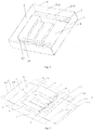
Fig. 1 is the front view of the formed packing box; -
Fig. 2 is the rear view of the formed packing box; -
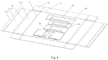
Fig. 3 is the rear view of the expanded packing box; -
Fig. 4 is the front view of the expanded packing box; - Meanings of the signs in the attached drawings:
Thebasal surface 1, thefirst side surfaces 2, the surfaces A 2-1, the surfaces B 2-2, the surfaces C 2-3, thesecond side surfaces 3, the first folding marks 4, the second wall surface 5, the fourth folding marks 6, the first bulges 7, the turn-over edges 8, thefirst wall surfaces 9, thethird wall surfaces 10, thefourth wall surfaces 12, the sixth folding marks 13, the fifth folding marks 14, the second folding marks 15 and thethird folding marks 16. - To better understand the technical content of the invention, specific embodiments are illustrated in connection with the attached drawings hereinafter.
- All aspects of the invention are described with reference to the attached drawings in the disclosure, and a number of embodiments described are illustrated in the attached drawings. The embodiments of the disclosure are not necessarily intended to include all the aspects of the invention. It should be understood that various ideas and embodiments presented hereinabove, as well as the ideas and implementations described hereinafter in more details can be implemented in any of many ways, since the ideas and embodiments disclosed in the invention are not limited to any implementation. In addition, some aspects disclosed in the invention can be used independently or in combination with any of other aspects disclosed in the invention.
- A packing box as shown in
Figs. 1-4 comprises abasal surface 1, side surfaces and containing spaces. - The side surfaces are arranged around the
basal surface 1, and form a one-piece planar structure with thebasal surface 1, the side surfaces and thebasal surface 1 formfirst folding marks 4 used to fold along thefirst folding marks 4 and form a space for the packing box. The match between the side surfaces and thebasal surface 1 is common in the existing packing box technology, the packing box is flattened during transportation and storage; to assemble the packing box, the side surfaces match mutually, so that the side surfaces are vertical to thebasal surface 1 and steadily and mutually match. - In order to contain corresponding articles in the packing box, as shown in
Fig. 1 , a plurality of holes are opened on thebasal surface 1, and the containing spaces are fixed on thebasal surface 1, with the holes used as openings thereof. - The containing spaces are surrounded by a plurality of wall surfaces, the wall surfaces unparallel to the
basal surface 1 when the containing spaces are expanded are defined as unparallel wall surfaces, the other wall surfaces are parallel wall surfaces, and a plurality of second folding marks 15 are formed on the unparallel wall surfaces to be used to fold and expand the corresponding wall surfaces; wherein, when the unparallel wall surfaces are folded, the internal cavities of the containing spaces disappear and the containing spaces are retracted, and when the unparallel wall surfaces are expanded, the containing spaces are expanded. - When the packing box is not in use, e.g., during transportation and storage, the containing spaces are retracted, the wall surfaces of the containing spaces are folded in order and are nearly parallel to the
basal surface 1, and the side surfaces and thebasal surface 1 are also flat as one piece. Therefore, the entire packing box occupies a space which is nearly a plane, thus reducing the space and not damaging the packing box structure when being overlaid for transportation or storage. - Specifically, the wall surfaces of the containing spaces comprise first wall surfaces 9 and second wall surfaces 5, wherein the first wall surfaces 9 are the unparallel wall surfaces, the second wall surfaces 5 are connected with the first wall surfaces 9 and are the parallel wall surfaces, and second folding marks 15 parallel to the
basal surface 1 are arranged on the first wall surfaces 9. The first wall surfaces 9 and the second wall surfaces 5 match to form the main side wall surfaces of the containing spaces. - In order to easily expand the wall surfaces of the containing spaces, the first wall surfaces are folded toward the inside of the containing spaces. Accordingly, the first wall surfaces 9 and the second folding marks 15 can be pushed to expand through the hole toward the outside of the containing spaces.
- Further, in order to stabilize the expanded state of the containing spaces and expand the wall surfaces of the containing spaces, the wall surfaces of the containing spaces also comprise third wall surfaces 10 which are fixedly connected to the
basal surface 1 and form a one-piece structure with thebasal surface 1, third folding marks 16 are formed between the third wall surfaces 10 and thebasal surface 1, and are arranged along partial edges of the holes corresponding to the containing spaces. As shown inFig. 4 , to expand the containing spaces, the third wall surfaces 10 are folded along the third folding marks 16 toward the inside of the containing spaces to expand the unparallel wall surfaces; to fold the containing spaces, the third wall surfaces 10 are folded along the third folding marks 16 toward thebasal surface 1 to fold the unparallel wall surfaces. - In order to expand the first wall surfaces 9 effectively, the edges of the third wall surfaces 10 adjacent to the third folding marks 16 at least sweep through the first wall surfaces 9 and the second folding marks 15 thereon in the path in which the third wall surfaces 10 are folded toward the inside of the containing spaces. Accordingly, the second folding marks 15 and the first wall surfaces 9 are pushed toward the outside of the containing spaces by the edges of the third wall surfaces 10, so that the containing spaces are expanded, and static friction force generated through contact between the third wall surfaces 10 and the first and second wall surfaces 9 and 5 stabilizes the third wall surfaces 10. In the embodiment, the containing spaces as shown in the figure are regular rectangular structures, thus the third wall surfaces 10 rotate along the third folding marks 16 by 90°, and is then vertical to the basal surface; at the time, the third wall surfaces 10 move to position, and can act as supports for the first wall surfaces 9 to prevent retraction of the first wall surfaces 9.
- Further, in the specific embodiment of the invention, in order for the third wall surfaces 10 to support the first wall surfaces 9 and the second wall surfaces 5, the radial length of the third wall surfaces 10 along the third folding marks 16 as the axes is equal to the depth of the containing spaces with the holes as the openings, thus the first wall surfaces 9 and the second wall surfaces 5 are supported by the side edges of the third wall surfaces 10 and the containing spaces are stabilized.
- In order to better stabilize the containing spaces and facilitate expansion and folding of the containing spaces, the hardness is considered such that the hardness of the first wall surfaces 10 of the containing spaces is lower than the hardness of the third wall surfaces 10, so that the third wall surfaces 10 push the first wall surfaces 9 more effectively, and better support the first wall surfaces 9 and even the second wall surfaces 5.
- Further, in the embodiment of the invention, the third wall surfaces 10 are formed by extending the basal surface; in consideration of using the basal surface as an important supporting surface after the entire packing box is formed, in the specific embodiment of the invention, the hardness of the
basal surface 1 is higher than or equal to the hardness of the third wall surfaces 10. - Specifically, as shown in
Figs. 1-4 , in the specific embodiment of the invention, a plurality of containing spaces are arranged, in each containing space, two first wall surfaces 9 are arranged, the second wall surface 5 is located between the two first wall surfaces 9 and forms one piece with the first wall surfaces 9, the containing space is fixed on thebasal surface 1 through the two first wall surfaces 9, and the path along which the first wall surfaces 9 are fixed with thebasal surface 1 is the partial edges of the hole; the two ends of the one-piece structure formed by the first wall surfaces 9 and the second wall surface 5, which are not fixed with thebasal surface 1, are the ends of the containing space. - Two third wall surfaces 10 are arranged, the
third folding mark 16 between eachthird wall surface 10 and thebasal surface 1 is arranged along the hole edge except the hole edges along which the first wall surfaces 9 are fixed with thebasal surface 1, and is respectively corresponding to the position of each end; the two edges of the third wall surfaces 10 adjacent to the third folding marks 16 respectively sweep through the two first wall surfaces 9 and the second folding marks 4 thereon in the path in which the third wall surfaces 10 are folded toward the inside of the containing spaces. - In the embodiment of the invention, the one-piece structures formed by the first wall surfaces 9 and the second wall surfaces 5 are made of paper material with the thickness and hardness lower than the thickness and hardness of the
basal surface 1, the first wall surfaces 9 are fixedly connected to thebasal surface 1 through gluing or another means, and the third wall surfaces 10 are made of paper material which is the same as the paper material of thebasal surface 1, and is fixedly connected to thebasal surface 1. Therefore, the third wall surfaces 10 with higher hardness and thickness can effectively support the first wall surfaces 9 and the second wall surfaces 5. - Preferably, in the specific embodiment of the invention, fourth wall surfaces 12 are also arranged on each containing space, the fourth wall surfaces 12 are arranged on the end surfaces formed by the ends and are mutually connected with the first wall surfaces 9 and the second wall surface 5, and sixth folding marks 13 are arranged on the fourth wall surfaces 12 to fold and expand the fourth wall surfaces 12. The fourth wall surfaces 12 are used to match the first wall surfaces 9 and the second wall surface 5 to form the side walls of the containing space, and can also be used as stops for the third wall surfaces 10 which move to position, and thus the third wall surfaces 10 overlap with the fourth wall surfaces 12 after moving to position.
- In the specific embodiment of the invention, the fourth wall surfaces 12 and the second wall surfaces 5 form one-piece structures, and are fixed on the first wall surfaces through gluing or another means.
- In the specific embodiment of the invention, the side surfaces mentioned in the above scheme are also designed in a new way, which will be described hereinafter.
- The side surfaces comprise first side surfaces 2 and second side surfaces 3 which are arranged at interval and match mutually when being folded to form the vertical surfaces of the packing box.
- Wherein, the first side surfaces 2 at least comprise surfaces A 2-1, surfaces B 2-2 and surfaces C 2-3 which are connected in sequence, the first side surfaces 2 are connected to the
basal surface 1 through the surfaces A 2-1, first folding marks 4 are arranged between the first side surfaces 2 and thebasal surface 1, the surfaces A 2-2 and the surfaces B 2-2 have the same size, between which fourth folding marks 6 are arranged, and fifth folding marks 14 are arranged between the surfaces B 2-2 and the surfaces C 2-3; the first folding marks 4, the fourth folding marks 6 and the fifth folding marks 14 are parallel mutually. - The first side surfaces 2 are folded toward the inside of the
basal surface 1 in sequence to form the first folding marks 4, the fourth folding marks 6 and the fifth folding marks 14 to realize folding of the first side surfaces 2, the surfaces A 2-1 and the surfaces B 2-2 overlap mutually, and the surfaces C 2-3 are attached on one side of thebasal surface 1. -
First bulges 7 are arranged on thebasal surface 1 near the first folding marks 4, with the thickness larger than the thickness of the surfaces C 2-3. - After the first side surfaces 2 are folded, the outer edges of the surfaces C 2-3 parallel to the fifth folding marks 14 abut against the outer side walls of the
first bulges 7 close to the first folding marks 4. Therefore, after being folded, the first side surfaces 2 can be firmly positioned through abutting between the surfaces C 2-3 and thefirst bulges 7 and the elasticity of the material without additional fixing. In order to better attach the surfaces C 2-3, thefirst bulges 7 are preferably long strips with the length equal to or slightly less than the length of the surfaces C 2-3. - Similarly to the existing technology, turn-over edges 8 are arranged on the second side surfaces 3, and sixth folding marks 13 are arranged between the turn-over edges 8 and the second side surfaces 3 such that the second side surfaces 3 are folded toward the inside of the
basal surface 1 through the first folding marks 4 and folded toward the gaps between the surfaces A2-1 and the surfaces B 2-2 through the sixth folding marks 13, so that the turn-over edges 8 are located in the gaps the surfaces A 2-1 and the surfaces B 2-2. - Therefore, the side surfaces match mutually to form steady vertical surfaces, and the originally flat packing box becomes a stereoscopic structure.
- The specific embodiment of the invention also disclose a method of using the packing box, through which the expanded packing box is folded:
- Side part: the side surfaces are folded toward the
basal surface 1 along the first folding marks 4, so that a space is formed for the packing box; - Containing space part: the third wall surfaces 10 are folded along the third folding marks 16 toward the inside of the containing spaces through the holes, so as to expand the unparallel wall surfaces in the containing spaces to form the containing spaces.
- Wherein, when the side parts are folded, the first side surfaces 2 are folded toward the inside of the
basal surface 1 in sequence to form the first folding marks 4, the fourth folding marks 6 and the fifth folding marks 14, so that the surfaces A 2-1 and the surfaces B 2-2 overlap mutually, and the surfaces C 2-3 are attached on one side of thebasal surface 1; the second side surfaces 3 are folded toward the inside of thebasal surface 1 through the first folding marks 4 and folded toward the gaps between the surfaces A 2-1 and the surfaces B 2-2 through the sixth folding marks 13, so that the turn-over edges 8 are located in the gaps the surfaces A 2-1 and the surfaces B 2-2. - By using the packing box and the using method in the specific embodiment of the invention, the space can be reduced during packing box transportation and storage, the packing box can be used very conveniently and quickly without the need of additional fixing tools, and a steady and reliable structure can be formed finally. Therefore, the packing box and the using method have broad application prospect.
- The invention has been disclosed above by way of a preferred embodiment; however, the preferred embodiment is not intended to limit the invention. Those of ordinary knowledge of the technical field of the invention may make various changes and modifications, without departing from the spirit and scope of the invention. Therefore, the protection scope of the invention shall be limited by the protection scope of the claims.
Claims (13)
- A packing box, wherein the packing box comprises a basal surface (1), side surfaces and containing spaces;
the side surfaces are arranged around the basal surface (1), and form a one-piece planar structure with the basal surface (1), the side surfaces and the basal surface (1) form first folding marks (4) used to fold along the first folding marks (4) and form a space for the packing box;
a plurality of holes are opened on the basal surface (1), and the containing spaces are fixed on the basal surface (1), with the holes used as openings thereof; characterized in that
each containing space is surrounded by a plurality of wall surfaces, the wall surfaces unparallel to the basal surface (1) when the containing spaces are expanded are defined as unparallel wall surfaces, the other wall surfaces are parallel wall surfaces, and a plurality of second folding marks (15) are formed on the unparallel wall surfaces to be used to fold and expand the corresponding wall surfaces; wherein, when the unparallel wall surfaces are folded, the internal cavities of the containing spaces disappear and the containing spaces are retracted, and when the unparallel wall surfaces are expanded, the containing spaces are expanded; and,
wherein
the wall surfaces of each containing space comprise first wall surfaces (9) and a second wall surface, wherein the first wall surfaces (9) are the unparallel wall surfaces, the second wall surface (5) is connected with the first wall surfaces (9) and is the parallel wall surface, and second folding marks (15) parallel to the basal surface (1) are arranged on the first wall surfaces. - A packing box according to Claim 1, characterized in that the first wall surfaces (9) are folded toward the inside of the containing spaces.
- A packing box according to Claim 2, characterized in that the wall surfaces of each containing space also comprise third wall surfaces (10) which are fixedly connected to the basal surface (1) and form a one-piece structure with the basal surface (1), third folding marks (16) are formed between the third wall surfaces (10) and the basal surface (1), are arranged along partial edges of the holes corresponding to the containing spaces, and are used to fold the third wall surfaces (10) along the third folding marks (16) toward the inside of the containing spaces to expand the unparallel wall surfaces and fold the third wall surfaces (10) along the third folding marks (16) toward the basal surface (1) to fold the unparallel wall surfaces.
- A packing box according to Claim 3, characterized in that the edges of the third wall surfaces (10) adjacent to the third folding marks (16) at least sweep through the first wall surfaces (9) and the second folding marks (15) thereon in the path in which the third wall surfaces (10) are folded toward the inside of the containing spaces.
- A packing box according to Claim 4, characterized in that the radial length of the third wall surfaces (10) along the third folding marks (16) as the axes is equal to the depth of the containing spaces with the holes as the openings.
- A packing box according to any of Claims 3-5, characterized in that the hardness of the first wall surfaces (9) of the containing spaces is lower than the hardness of the third wall surfaces.
- A packing box according to Claim 6, characterized in that the hardness of the basal surface (1) is higher than or equal to the hardness of the third wall surfaces.
- A packing box according to Claim 4, characterized in that in each containing space, two first wall surfaces (9) are arranged, the second wall surface (5) is located between the two first wall surfaces (9) and forms one piece with the first wall surfaces, the containing space is fixed on the basal surface (1) through the two first wall surfaces, and the path along which the first wall surfaces (9) are fixed with the basal surface (1) is the partial edges of the hole; the two ends of the one-piece structure formed by the first wall surfaces (9) and the second wall surface, which are not fixed with the basal surface (1), are the ends of the containing space;
Two third wall surfaces (10) are arranged, the third folding mark between each third wall surface and the basal surface (1) is arranged along the hole edge except the hole edges along which the first wall surfaces (9) are fixed with the basal surface (1), and is respectively corresponding to the position of each end; the two edges of the third wall surfaces (10) adjacent to the third folding marks (16) respectively sweep through the two first wall surfaces (9) and the second folding marks (15) thereon in the path in which the third wall surfaces (10) are folded toward the inside of the containing spaces. - A packing box according to Claim 8, characterized in that in that fourth wall surfaces (12) are also arranged on each containing space, the fourth wall surfaces (12) are arranged on the end surfaces formed by the ends and are mutually connected with the first wall surfaces (9) and the second wall surface, and sixth folding marks (13) are arranged on the fourth wall surfaces (12) to fold and expand the fourth wall surfaces.
- A packing box according to any of Claims 1-4, characterized in that the side surfaces comprise first side surfaces (2) and second side surfaces (3) which are arranged at interval and match mutually when being folded to form the vertical surfaces of the packing box;
Wherein, the first side surfaces (2) at least comprise surfaces A (2-1), surfaces B (2-2) and surfaces C (2-3) which are connected in sequence, the first side surfaces (2) are connected to the basal surface (1) through the surfaces A (2-1), first folding marks (4) are arranged between the first side surfaces (2) and the basal surface (1), the surfaces A (2-1) and the surfaces B (2-2) have the same size, between which fourth folding marks (6) are arranged, and fifth folding marks (14) are arranged between the surfaces B (2-2) and the surfaces C (2-3); the first folding marks, the fourth folding marks (6) and the fifth folding marks (14) are parallel mutually;
The first side surfaces (2) are folded toward the inside of the basal surface (1) in sequence to form the first folding marks, the fourth folding marks (6) and the fifth folding marks (14) to realize folding of the first side surfaces (2), the surfaces A (2-1) and the surfaces B (2-2) overlap mutually, and the surfaces C (2-3) are attached on one side of the basal surface (1);
First bulges (7) are arranged on the basal surface (1) near the first folding marks, with the thickness larger than the thickness of the surfaces C (2-3);
After the first side surfaces (2) are folded, the outer edges of the surfaces C (2-3) parallel to the fifth folding marks (14) abut against the outer side walls of the first bulges (7) close to the first folding marks. - A packing box according to Claim 10, characterized in that turn-over edges (8) are arranged on the second side surfaces (3), and sixth folding marks (13) are arranged between the turn-over edges (8) and the second side surfaces (3) such that the second side surfaces (3) are folded toward the inside of the basal surface (1) through the first folding marks (4) and folded toward the gaps between the surfaces A (2-1) and the surfaces B (2-2) through the sixth folding marks, so that the turn-over edges (8) are located in the gaps the surfaces A (2-1) and the surfaces B (2-2).
- A method of using the packing box according to any of Claims 3-11, characterized in that the expanded packing box is folded by using the following method:: the side surfaces of side part are folded toward the basal surface (1) along the first folding marks (4), so that a space is formed for the packing box;: the third wall surfaces (10) of containing space part are folded along the third folding marks (16) toward the inside of the containing spaces through the holes, so as to expand the unparallel wall surfaces in the containing spaces to form the containing spaces.
- A method of using the packing box according to Claim 12, characterized in that when the side parts are folded, the first side surfaces (2) are folded toward the inside of the basal surface (1) in sequence to form the first folding marks, the fourth folding marks (6) and the fifth folding marks (14), so that the surfaces A (2-1) and the surfaces B (2-2) overlap mutually, and the surfaces C (2-3) are attached on one side of the basal surface (1); the second side surfaces (3) are folded toward the inside of the basal surface (1) through the first folding marks (4) and folded toward the gaps between the surfaces A (2-1) and the surfaces B (2-2) through the sixth folding marks, so that the turn-over edges (8) are located in the gaps the surfaces A (2-1) and the surfaces B (2-2).
Applications Claiming Priority (1)
| Application Number | Priority Date | Filing Date | Title |
|---|---|---|---|
| PCT/CN2018/108660 WO2020062147A1 (en) | 2018-09-29 | 2018-09-29 | Packaging box and method for using same |
Publications (3)
| Publication Number | Publication Date |
|---|---|
| EP3656692A4 EP3656692A4 (en) | 2020-05-27 |
| EP3656692A1 EP3656692A1 (en) | 2020-05-27 |
| EP3656692B1 true EP3656692B1 (en) | 2021-03-31 |
Family
ID=69952619
Family Applications (1)
| Application Number | Title | Priority Date | Filing Date |
|---|---|---|---|
| EP18875013.7A Active EP3656692B1 (en) | 2018-09-29 | 2018-09-29 | Packaging box and method for using same |
Country Status (4)
| Country | Link |
|---|---|
| US (1) | US11352167B2 (en) |
| EP (1) | EP3656692B1 (en) |
| ES (1) | ES2879952T3 (en) |
| WO (1) | WO2020062147A1 (en) |
Families Citing this family (2)
| Publication number | Priority date | Publication date | Assignee | Title |
|---|---|---|---|---|
| USD1061183S1 (en) * | 2022-01-20 | 2025-02-11 | Belgo Holdings LLC | Food holder |
| USD1063571S1 (en) * | 2022-01-20 | 2025-02-25 | Belgo Holdings LLC | Food holder |
Family Cites Families (13)
| Publication number | Priority date | Publication date | Assignee | Title |
|---|---|---|---|---|
| US2771232A (en) | 1953-08-04 | 1956-11-20 | Kenneth M Reed | Stackable service tray |
| US3104046A (en) * | 1961-07-07 | 1963-09-17 | Fed Paper Board Co Inc | Article carrier |
| US3730419A (en) * | 1971-07-14 | 1973-05-01 | Container Corp | Carry-out tray |
| DE3701606A1 (en) * | 1987-01-21 | 1988-08-04 | Walter W Dipl Ing Graffunder | Folding container |
| DE4009852A1 (en) * | 1990-03-23 | 1991-09-26 | Urban Dipl Ing Stricker | Recyclable plastics packaging box - designed to collapse or fold to flat body |
| JP3028190B2 (en) * | 1995-07-11 | 2000-04-04 | 株式会社クラウン・パッケージ | Paper box |
| US7317573B2 (en) | 2005-01-18 | 2008-01-08 | Kid Stuff Marketing, Inc. | Carton with removable three-dimensional viewer |
| US7484653B2 (en) * | 2006-06-21 | 2009-02-03 | International Paper Co. | Cup holder tray |
| CN201457825U (en) * | 2009-06-19 | 2010-05-12 | 华健 | square paper box |
| IT1399868B1 (en) * | 2010-05-11 | 2013-05-09 | Nampak Healthcare Italy S R L Ora Contego Packaging Italy Srl | PACKAGING FOR PHARMACEUTICAL PRODUCTS, IN PARTICULAR FOR PARENTERAL PRODUCTS |
| US8887984B2 (en) * | 2011-04-26 | 2014-11-18 | Rock-Tenn Shared Services, Llc | Tray for supporting containers and a blank for making the same |
| US20150282648A1 (en) * | 2014-04-03 | 2015-10-08 | Robert Stephen Zaccardo | Food And Beverage Serving Tray Having Automatic Latching Sides |
| CN206704725U (en) * | 2017-04-14 | 2017-12-05 | 苏州伍洲设计包装有限公司 | A kind of wine box that can effectively prevent cassette bottom from ftractureing |
-
2018
- 2018-09-29 WO PCT/CN2018/108660 patent/WO2020062147A1/en not_active Ceased
- 2018-09-29 ES ES18875013T patent/ES2879952T3/en active Active
- 2018-09-29 US US16/629,426 patent/US11352167B2/en active Active
- 2018-09-29 EP EP18875013.7A patent/EP3656692B1/en active Active
Non-Patent Citations (1)
| Title |
|---|
| None * |
Also Published As
| Publication number | Publication date |
|---|---|
| EP3656692A4 (en) | 2020-05-27 |
| US11352167B2 (en) | 2022-06-07 |
| ES2879952T3 (en) | 2021-11-23 |
| WO2020062147A1 (en) | 2020-04-02 |
| EP3656692A1 (en) | 2020-05-27 |
| US20210094726A1 (en) | 2021-04-01 |
Similar Documents
| Publication | Publication Date | Title |
|---|---|---|
| US9409669B2 (en) | Tray for supporting containers and a blank for making the same | |
| CN204624082U (en) | Packing box (Chinese character' jiangsu | |
| EP3656692A1 (en) | Packaging box and method for using same | |
| JP2019531232A (en) | Tray with cup holder and hand hole | |
| US20110272312A1 (en) | Article of and method for forming a generally orthogonal corner arrangement having no external fasteners or protrusions | |
| CN205661769U (en) | Take partition function packing carton | |
| JP2011207482A (en) | Assembly partition made of paper | |
| US9988175B2 (en) | Sectioned corrugated sleeve for thermal gel packs | |
| CN205010626U (en) | Novel clutch accessory packing box | |
| CN204056521U (en) | By individual being made into one of cardboard packing box | |
| KR101883072B1 (en) | Packaging box | |
| WO2023100020A1 (en) | An inner support structure of a packaging box with variable size and a packaging box | |
| CN209097211U (en) | Packing box | |
| CN203699014U (en) | Packaging box for craft porcelain dish | |
| CN203958803U (en) | Inserting type packing box | |
| KR200464048Y1 (en) | Handle Packing Box | |
| CN205256836U (en) | Monolithic paper fold and pack box | |
| CN214165586U (en) | An upper and lower integrated multi-slot packing box | |
| CN102152886A (en) | Corrugated packaging box of wine and preparation technology thereof | |
| JP3192286U (en) | Paper container | |
| CN212074688U (en) | A paper-formed coffee packaging box | |
| CN210971872U (en) | box | |
| CN105416890B (en) | A container for transporting electrical or optical cables | |
| JP2007055629A (en) | Packaging box | |
| JP2018090260A (en) | Cardboard buffer material |
Legal Events
| Date | Code | Title | Description |
|---|---|---|---|
| STAA | Information on the status of an ep patent application or granted ep patent |
Free format text: STATUS: UNKNOWN |
|
| STAA | Information on the status of an ep patent application or granted ep patent |
Free format text: STATUS: THE INTERNATIONAL PUBLICATION HAS BEEN MADE |
|
| PUAI | Public reference made under article 153(3) epc to a published international application that has entered the european phase |
Free format text: ORIGINAL CODE: 0009012 |
|
| STAA | Information on the status of an ep patent application or granted ep patent |
Free format text: STATUS: REQUEST FOR EXAMINATION WAS MADE |
|
| 17P | Request for examination filed |
Effective date: 20190605 |
|
| A4 | Supplementary search report drawn up and despatched |
Effective date: 20191112 |
|
| AK | Designated contracting states |
Kind code of ref document: A1 Designated state(s): AL AT BE BG CH CY CZ DE DK EE ES FI FR GB GR HR HU IE IS IT LI LT LU LV MC MK MT NL NO PL PT RO RS SE SI SK SM TR |
|
| AX | Request for extension of the european patent |
Extension state: BA ME |
|
| GRAP | Despatch of communication of intention to grant a patent |
Free format text: ORIGINAL CODE: EPIDOSNIGR1 |
|
| STAA | Information on the status of an ep patent application or granted ep patent |
Free format text: STATUS: GRANT OF PATENT IS INTENDED |
|
| RIC1 | Information provided on ipc code assigned before grant |
Ipc: B65D 5/20 20060101ALI20201009BHEP Ipc: B65D 5/36 20060101ALI20201009BHEP Ipc: B65D 5/42 20060101ALI20201009BHEP Ipc: B65D 5/50 20060101AFI20201009BHEP Ipc: B65D 5/22 20060101ALI20201009BHEP |
|
| INTG | Intention to grant announced |
Effective date: 20201029 |
|
| GRAS | Grant fee paid |
Free format text: ORIGINAL CODE: EPIDOSNIGR3 |
|
| GRAA | (expected) grant |
Free format text: ORIGINAL CODE: 0009210 |
|
| STAA | Information on the status of an ep patent application or granted ep patent |
Free format text: STATUS: THE PATENT HAS BEEN GRANTED |
|
| AK | Designated contracting states |
Kind code of ref document: B1 Designated state(s): AL AT BE BG CH CY CZ DE DK EE ES FI FR GB GR HR HU IE IS IT LI LT LU LV MC MK MT NL NO PL PT RO RS SE SI SK SM TR |
|
| DAV | Request for validation of the european patent (deleted) | ||
| DAX | Request for extension of the european patent (deleted) | ||
| REG | Reference to a national code |
Ref country code: GB Ref legal event code: FG4D Ref country code: CH Ref legal event code: EP |
|
| REG | Reference to a national code |
Ref country code: AT Ref legal event code: REF Ref document number: 1376700 Country of ref document: AT Kind code of ref document: T Effective date: 20210415 |
|
| REG | Reference to a national code |
Ref country code: DE Ref legal event code: R096 Ref document number: 602018014933 Country of ref document: DE |
|
| REG | Reference to a national code |
Ref country code: IE Ref legal event code: FG4D |
|
| REG | Reference to a national code |
Ref country code: LT Ref legal event code: MG9D |
|
| PG25 | Lapsed in a contracting state [announced via postgrant information from national office to epo] |
Ref country code: BG Free format text: LAPSE BECAUSE OF FAILURE TO SUBMIT A TRANSLATION OF THE DESCRIPTION OR TO PAY THE FEE WITHIN THE PRESCRIBED TIME-LIMIT Effective date: 20210630 Ref country code: FI Free format text: LAPSE BECAUSE OF FAILURE TO SUBMIT A TRANSLATION OF THE DESCRIPTION OR TO PAY THE FEE WITHIN THE PRESCRIBED TIME-LIMIT Effective date: 20210331 Ref country code: HR Free format text: LAPSE BECAUSE OF FAILURE TO SUBMIT A TRANSLATION OF THE DESCRIPTION OR TO PAY THE FEE WITHIN THE PRESCRIBED TIME-LIMIT Effective date: 20210331 Ref country code: NO Free format text: LAPSE BECAUSE OF FAILURE TO SUBMIT A TRANSLATION OF THE DESCRIPTION OR TO PAY THE FEE WITHIN THE PRESCRIBED TIME-LIMIT Effective date: 20210630 |
|
| PG25 | Lapsed in a contracting state [announced via postgrant information from national office to epo] |
Ref country code: SE Free format text: LAPSE BECAUSE OF FAILURE TO SUBMIT A TRANSLATION OF THE DESCRIPTION OR TO PAY THE FEE WITHIN THE PRESCRIBED TIME-LIMIT Effective date: 20210331 Ref country code: LV Free format text: LAPSE BECAUSE OF FAILURE TO SUBMIT A TRANSLATION OF THE DESCRIPTION OR TO PAY THE FEE WITHIN THE PRESCRIBED TIME-LIMIT Effective date: 20210331 Ref country code: RS Free format text: LAPSE BECAUSE OF FAILURE TO SUBMIT A TRANSLATION OF THE DESCRIPTION OR TO PAY THE FEE WITHIN THE PRESCRIBED TIME-LIMIT Effective date: 20210331 |
|
| REG | Reference to a national code |
Ref country code: NL Ref legal event code: MP Effective date: 20210331 |
|
| REG | Reference to a national code |
Ref country code: AT Ref legal event code: MK05 Ref document number: 1376700 Country of ref document: AT Kind code of ref document: T Effective date: 20210331 |
|
| PG25 | Lapsed in a contracting state [announced via postgrant information from national office to epo] |
Ref country code: CZ Free format text: LAPSE BECAUSE OF FAILURE TO SUBMIT A TRANSLATION OF THE DESCRIPTION OR TO PAY THE FEE WITHIN THE PRESCRIBED TIME-LIMIT Effective date: 20210331 Ref country code: EE Free format text: LAPSE BECAUSE OF FAILURE TO SUBMIT A TRANSLATION OF THE DESCRIPTION OR TO PAY THE FEE WITHIN THE PRESCRIBED TIME-LIMIT Effective date: 20210331 Ref country code: LT Free format text: LAPSE BECAUSE OF FAILURE TO SUBMIT A TRANSLATION OF THE DESCRIPTION OR TO PAY THE FEE WITHIN THE PRESCRIBED TIME-LIMIT Effective date: 20210331 Ref country code: AT Free format text: LAPSE BECAUSE OF FAILURE TO SUBMIT A TRANSLATION OF THE DESCRIPTION OR TO PAY THE FEE WITHIN THE PRESCRIBED TIME-LIMIT Effective date: 20210331 Ref country code: NL Free format text: LAPSE BECAUSE OF FAILURE TO SUBMIT A TRANSLATION OF THE DESCRIPTION OR TO PAY THE FEE WITHIN THE PRESCRIBED TIME-LIMIT Effective date: 20210331 Ref country code: SM Free format text: LAPSE BECAUSE OF FAILURE TO SUBMIT A TRANSLATION OF THE DESCRIPTION OR TO PAY THE FEE WITHIN THE PRESCRIBED TIME-LIMIT Effective date: 20210331 |
|
| REG | Reference to a national code |
Ref country code: ES Ref legal event code: FG2A Ref document number: 2879952 Country of ref document: ES Kind code of ref document: T3 Effective date: 20211123 |
|
| PG25 | Lapsed in a contracting state [announced via postgrant information from national office to epo] |
Ref country code: IS Free format text: LAPSE BECAUSE OF FAILURE TO SUBMIT A TRANSLATION OF THE DESCRIPTION OR TO PAY THE FEE WITHIN THE PRESCRIBED TIME-LIMIT Effective date: 20210731 Ref country code: PL Free format text: LAPSE BECAUSE OF FAILURE TO SUBMIT A TRANSLATION OF THE DESCRIPTION OR TO PAY THE FEE WITHIN THE PRESCRIBED TIME-LIMIT Effective date: 20210331 Ref country code: SK Free format text: LAPSE BECAUSE OF FAILURE TO SUBMIT A TRANSLATION OF THE DESCRIPTION OR TO PAY THE FEE WITHIN THE PRESCRIBED TIME-LIMIT Effective date: 20210331 Ref country code: PT Free format text: LAPSE BECAUSE OF FAILURE TO SUBMIT A TRANSLATION OF THE DESCRIPTION OR TO PAY THE FEE WITHIN THE PRESCRIBED TIME-LIMIT Effective date: 20210802 Ref country code: RO Free format text: LAPSE BECAUSE OF FAILURE TO SUBMIT A TRANSLATION OF THE DESCRIPTION OR TO PAY THE FEE WITHIN THE PRESCRIBED TIME-LIMIT Effective date: 20210331 |
|
| REG | Reference to a national code |
Ref country code: DE Ref legal event code: R097 Ref document number: 602018014933 Country of ref document: DE |
|
| PG25 | Lapsed in a contracting state [announced via postgrant information from national office to epo] |
Ref country code: AL Free format text: LAPSE BECAUSE OF FAILURE TO SUBMIT A TRANSLATION OF THE DESCRIPTION OR TO PAY THE FEE WITHIN THE PRESCRIBED TIME-LIMIT Effective date: 20210331 Ref country code: DK Free format text: LAPSE BECAUSE OF FAILURE TO SUBMIT A TRANSLATION OF THE DESCRIPTION OR TO PAY THE FEE WITHIN THE PRESCRIBED TIME-LIMIT Effective date: 20210331 |
|
| PLBE | No opposition filed within time limit |
Free format text: ORIGINAL CODE: 0009261 |
|
| STAA | Information on the status of an ep patent application or granted ep patent |
Free format text: STATUS: NO OPPOSITION FILED WITHIN TIME LIMIT |
|
| 26N | No opposition filed |
Effective date: 20220104 |
|
| REG | Reference to a national code |
Ref country code: CH Ref legal event code: PL |
|
| REG | Reference to a national code |
Ref country code: BE Ref legal event code: MM Effective date: 20210930 |
|
| PG25 | Lapsed in a contracting state [announced via postgrant information from national office to epo] |
Ref country code: IS Free format text: LAPSE BECAUSE OF FAILURE TO SUBMIT A TRANSLATION OF THE DESCRIPTION OR TO PAY THE FEE WITHIN THE PRESCRIBED TIME-LIMIT Effective date: 20210731 Ref country code: MC Free format text: LAPSE BECAUSE OF FAILURE TO SUBMIT A TRANSLATION OF THE DESCRIPTION OR TO PAY THE FEE WITHIN THE PRESCRIBED TIME-LIMIT Effective date: 20210331 |
|
| PG25 | Lapsed in a contracting state [announced via postgrant information from national office to epo] |
Ref country code: LU Free format text: LAPSE BECAUSE OF NON-PAYMENT OF DUE FEES Effective date: 20210929 Ref country code: IE Free format text: LAPSE BECAUSE OF NON-PAYMENT OF DUE FEES Effective date: 20210929 Ref country code: BE Free format text: LAPSE BECAUSE OF NON-PAYMENT OF DUE FEES Effective date: 20210930 |
|
| PG25 | Lapsed in a contracting state [announced via postgrant information from national office to epo] |
Ref country code: LI Free format text: LAPSE BECAUSE OF NON-PAYMENT OF DUE FEES Effective date: 20210930 Ref country code: CH Free format text: LAPSE BECAUSE OF NON-PAYMENT OF DUE FEES Effective date: 20210930 |
|
| PG25 | Lapsed in a contracting state [announced via postgrant information from national office to epo] |
Ref country code: CY Free format text: LAPSE BECAUSE OF FAILURE TO SUBMIT A TRANSLATION OF THE DESCRIPTION OR TO PAY THE FEE WITHIN THE PRESCRIBED TIME-LIMIT Effective date: 20210331 |
|
| PG25 | Lapsed in a contracting state [announced via postgrant information from national office to epo] |
Ref country code: HU Free format text: LAPSE BECAUSE OF FAILURE TO SUBMIT A TRANSLATION OF THE DESCRIPTION OR TO PAY THE FEE WITHIN THE PRESCRIBED TIME-LIMIT; INVALID AB INITIO Effective date: 20180929 Ref country code: GR Free format text: LAPSE BECAUSE OF FAILURE TO SUBMIT A TRANSLATION OF THE DESCRIPTION OR TO PAY THE FEE WITHIN THE PRESCRIBED TIME-LIMIT Effective date: 20210331 |
|
| REG | Reference to a national code |
Ref country code: DE Ref legal event code: R081 Ref document number: 602018014933 Country of ref document: DE Owner name: INTERNATIONAL DESIGN PACKAGING CO., LTD., TONG, CN Free format text: FORMER OWNER: INTERNATIONAL DESIGN PACKING CO., LTD., SUZHOU CITY, JIANGSU, CN |
|
| REG | Reference to a national code |
Ref country code: DE Ref legal event code: R081 Ref document number: 602018014933 Country of ref document: DE Owner name: INTERNATIONAL DESIGN PACKAGING CO., LTD., TONG, CN Free format text: FORMER OWNER: INTERNATIONAL DESIGN PACKING CO., LTD., TONGCHENG, ANHUI, CN |
|
| PG25 | Lapsed in a contracting state [announced via postgrant information from national office to epo] |
Ref country code: MK Free format text: LAPSE BECAUSE OF FAILURE TO SUBMIT A TRANSLATION OF THE DESCRIPTION OR TO PAY THE FEE WITHIN THE PRESCRIBED TIME-LIMIT Effective date: 20210331 |
|
| PG25 | Lapsed in a contracting state [announced via postgrant information from national office to epo] |
Ref country code: TR Free format text: LAPSE BECAUSE OF FAILURE TO SUBMIT A TRANSLATION OF THE DESCRIPTION OR TO PAY THE FEE WITHIN THE PRESCRIBED TIME-LIMIT Effective date: 20210331 |
|
| REG | Reference to a national code |
Ref country code: ES Ref legal event code: PC2A Owner name: INTERNATIONAL DESIGN PACKAGING CO. LTD. Effective date: 20240924 |
|
| PG25 | Lapsed in a contracting state [announced via postgrant information from national office to epo] |
Ref country code: MT Free format text: LAPSE BECAUSE OF FAILURE TO SUBMIT A TRANSLATION OF THE DESCRIPTION OR TO PAY THE FEE WITHIN THE PRESCRIBED TIME-LIMIT Effective date: 20210331 |
|
| PGFP | Annual fee paid to national office [announced via postgrant information from national office to epo] |
Ref country code: DE Payment date: 20250819 Year of fee payment: 8 |
|
| PGFP | Annual fee paid to national office [announced via postgrant information from national office to epo] |
Ref country code: IT Payment date: 20250819 Year of fee payment: 8 |
|
| PGFP | Annual fee paid to national office [announced via postgrant information from national office to epo] |
Ref country code: GB Payment date: 20250818 Year of fee payment: 8 |
|
| PGFP | Annual fee paid to national office [announced via postgrant information from national office to epo] |
Ref country code: FR Payment date: 20250818 Year of fee payment: 8 |
|
| PGFP | Annual fee paid to national office [announced via postgrant information from national office to epo] |
Ref country code: ES Payment date: 20251001 Year of fee payment: 8 |