EP3656493A1 - Cutting insert and method for manufacturing cutting insert - Google Patents
Cutting insert and method for manufacturing cutting insert Download PDFInfo
- Publication number
- EP3656493A1 EP3656493A1 EP18834652.2A EP18834652A EP3656493A1 EP 3656493 A1 EP3656493 A1 EP 3656493A1 EP 18834652 A EP18834652 A EP 18834652A EP 3656493 A1 EP3656493 A1 EP 3656493A1
- Authority
- EP
- European Patent Office
- Prior art keywords
- coolant
- cutting insert
- guide groove
- cutting edge
- flank face
- Prior art date
- Legal status (The legal status is an assumption and is not a legal conclusion. Google has not performed a legal analysis and makes no representation as to the accuracy of the status listed.)
- Pending
Links
Images


Classifications
-
- B—PERFORMING OPERATIONS; TRANSPORTING
- B23—MACHINE TOOLS; METAL-WORKING NOT OTHERWISE PROVIDED FOR
- B23B—TURNING; BORING
- B23B27/00—Tools for turning or boring machines; Tools of a similar kind in general; Accessories therefor
- B23B27/14—Cutting tools of which the bits or tips or cutting inserts are of special material
- B23B27/16—Cutting tools of which the bits or tips or cutting inserts are of special material with exchangeable cutting bits or cutting inserts, e.g. able to be clamped
- B23B27/1603—Cutting tools of which the bits or tips or cutting inserts are of special material with exchangeable cutting bits or cutting inserts, e.g. able to be clamped with specially shaped plate-like exchangeable cutting inserts, e.g. chip-breaking groove
- B23B27/1611—Cutting tools of which the bits or tips or cutting inserts are of special material with exchangeable cutting bits or cutting inserts, e.g. able to be clamped with specially shaped plate-like exchangeable cutting inserts, e.g. chip-breaking groove characterised by having a special shape
-
- B—PERFORMING OPERATIONS; TRANSPORTING
- B23—MACHINE TOOLS; METAL-WORKING NOT OTHERWISE PROVIDED FOR
- B23B—TURNING; BORING
- B23B27/00—Tools for turning or boring machines; Tools of a similar kind in general; Accessories therefor
- B23B27/10—Cutting tools with special provision for cooling
-
- B—PERFORMING OPERATIONS; TRANSPORTING
- B23—MACHINE TOOLS; METAL-WORKING NOT OTHERWISE PROVIDED FOR
- B23B—TURNING; BORING
- B23B27/00—Tools for turning or boring machines; Tools of a similar kind in general; Accessories therefor
- B23B27/14—Cutting tools of which the bits or tips or cutting inserts are of special material
-
- B—PERFORMING OPERATIONS; TRANSPORTING
- B23—MACHINE TOOLS; METAL-WORKING NOT OTHERWISE PROVIDED FOR
- B23C—MILLING
- B23C5/00—Milling-cutters
- B23C5/16—Milling-cutters characterised by physical features other than shape
- B23C5/20—Milling-cutters characterised by physical features other than shape with removable cutter bits or teeth or cutting inserts
- B23C5/202—Plate-like cutting inserts with special form
-
- B—PERFORMING OPERATIONS; TRANSPORTING
- B23—MACHINE TOOLS; METAL-WORKING NOT OTHERWISE PROVIDED FOR
- B23C—MILLING
- B23C5/00—Milling-cutters
- B23C5/28—Features relating to lubricating or cooling
- B23C5/283—Cutting inserts with internal coolant channels
-
- B—PERFORMING OPERATIONS; TRANSPORTING
- B23—MACHINE TOOLS; METAL-WORKING NOT OTHERWISE PROVIDED FOR
- B23P—METAL-WORKING NOT OTHERWISE PROVIDED FOR; COMBINED OPERATIONS; UNIVERSAL MACHINE TOOLS
- B23P15/00—Making specific metal objects by operations not covered by a single other subclass or a group in this subclass
- B23P15/28—Making specific metal objects by operations not covered by a single other subclass or a group in this subclass cutting tools
-
- B—PERFORMING OPERATIONS; TRANSPORTING
- B23—MACHINE TOOLS; METAL-WORKING NOT OTHERWISE PROVIDED FOR
- B23Q—DETAILS, COMPONENTS, OR ACCESSORIES FOR MACHINE TOOLS, e.g. ARRANGEMENTS FOR COPYING OR CONTROLLING; MACHINE TOOLS IN GENERAL CHARACTERISED BY THE CONSTRUCTION OF PARTICULAR DETAILS OR COMPONENTS; COMBINATIONS OR ASSOCIATIONS OF METAL-WORKING MACHINES, NOT DIRECTED TO A PARTICULAR RESULT
- B23Q11/00—Accessories fitted to machine tools for keeping tools or parts of the machine in good working condition or for cooling work; Safety devices specially combined with or arranged in, or specially adapted for use in connection with, machine tools
- B23Q11/10—Arrangements for cooling or lubricating tools or work
- B23Q11/1015—Arrangements for cooling or lubricating tools or work by supplying a cutting liquid through the spindle
-
- B—PERFORMING OPERATIONS; TRANSPORTING
- B23—MACHINE TOOLS; METAL-WORKING NOT OTHERWISE PROVIDED FOR
- B23B—TURNING; BORING
- B23B2200/00—Details of cutting inserts
- B23B2200/04—Overall shape
- B23B2200/0428—Lozenge
- B23B2200/0433—Lozenge rounded
-
- B—PERFORMING OPERATIONS; TRANSPORTING
- B23—MACHINE TOOLS; METAL-WORKING NOT OTHERWISE PROVIDED FOR
- B23B—TURNING; BORING
- B23B2200/00—Details of cutting inserts
- B23B2200/12—Side or flank surfaces
- B23B2200/128—Side or flank surfaces with one or more grooves
-
- B—PERFORMING OPERATIONS; TRANSPORTING
- B23—MACHINE TOOLS; METAL-WORKING NOT OTHERWISE PROVIDED FOR
- B23B—TURNING; BORING
- B23B2222/00—Materials of tools or workpieces composed of metals, alloys or metal matrices
- B23B2222/28—Details of hard metal, i.e. cemented carbide
-
- B—PERFORMING OPERATIONS; TRANSPORTING
- B23—MACHINE TOOLS; METAL-WORKING NOT OTHERWISE PROVIDED FOR
- B23B—TURNING; BORING
- B23B2224/00—Materials of tools or workpieces composed of a compound including a metal
-
- B—PERFORMING OPERATIONS; TRANSPORTING
- B23—MACHINE TOOLS; METAL-WORKING NOT OTHERWISE PROVIDED FOR
- B23B—TURNING; BORING
- B23B2226/00—Materials of tools or workpieces not comprising a metal
- B23B2226/12—Boron nitride
- B23B2226/125—Boron nitride cubic [CBN]
-
- B—PERFORMING OPERATIONS; TRANSPORTING
- B23—MACHINE TOOLS; METAL-WORKING NOT OTHERWISE PROVIDED FOR
- B23B—TURNING; BORING
- B23B2250/00—Compensating adverse effects during turning, boring or drilling
- B23B2250/12—Cooling and lubrication
-
- B—PERFORMING OPERATIONS; TRANSPORTING
- B23—MACHINE TOOLS; METAL-WORKING NOT OTHERWISE PROVIDED FOR
- B23B—TURNING; BORING
- B23B2250/00—Compensating adverse effects during turning, boring or drilling
- B23B2250/12—Cooling and lubrication
- B23B2250/121—Insert with coolant channels
-
- B—PERFORMING OPERATIONS; TRANSPORTING
- B23—MACHINE TOOLS; METAL-WORKING NOT OTHERWISE PROVIDED FOR
- B23C—MILLING
- B23C2200/00—Details of milling cutting inserts
- B23C2200/12—Side or flank surfaces
- B23C2200/128—Side or flank surfaces with one or more grooves
-
- B—PERFORMING OPERATIONS; TRANSPORTING
- B23—MACHINE TOOLS; METAL-WORKING NOT OTHERWISE PROVIDED FOR
- B23C—MILLING
- B23C2250/00—Compensating adverse effects during milling
- B23C2250/12—Cooling and lubrication
Definitions
- the present disclosure relates to a cutting insert and a method for manufacturing the cutting insert.
- the present application claims a priority based on Japanese Patent Application No. 2017-140115 filed on July 19, 2017 , the entire content of which is incorporated herein by reference.
- Patent Literature 1 Japanese Patent Laying-Open No. 2016-190275
- a coolant holding portion is formed in a flank face of the cutting insert described in Patent Literature 1.
- the coolant holding portion is constituted of a plurality of grooves and a plurality of ribs formed in the flank face.
- the cutting insert described in Patent Literature 1 is attached to a tool body. Inside the tool body, a path for supplying the coolant is formed. This path opens in a surface of the tool body, thereby forming a coolant supply hole. Part of coolant sent out from the coolant supply hole is ejected onto the flank face of the cutting insert described in Patent Literature 1, and is accordingly supplied to the coolant holding portion.
- a cutting insert includes: a rake face; a flank face continuous to the rake face; and a cutting edge constituted of a ridgeline between the rake face and the flank face.
- a coolant flow path is provided inside the cutting insert. One end portion of the coolant flow path opens in the flank face to form a coolant ejection hole.
- the flank face is provided with a coolant guide groove extending from the coolant ejection hole toward the cutting edge with a base end portion of the coolant guide groove being connected to the coolant ejection hole and with a front end portion of the coolant guide groove being disposed at a position close to the cutting edge relative to the base end portion.
- a method for manufacturing a cutting insert according to one embodiment of the present disclosure is a method for manufacturing the above-described cutting insert.
- the method for manufacturing the cutting insert according to one embodiment of the present disclosure includes: preparing a shaped body for the cutting insert; forming the rake face, the flank face, and the cutting edge in the shaped body; forming the coolant flow path inside the shaped body and forming the coolant ejection hole in the flank face; and forming the coolant guide groove in the flank face.
- the coolant supply hole that opens in the surface of the tool body is disposed at a position away from the coolant holding portion formed in the cutting insert. Particularly, when a plate is disposed between the cutting insert and the tool body, the coolant supply hole is further away from the coolant holding portion. Moreover, when cutting a workpiece using the cutting insert described in Patent Literature 1, the flank face of the cutting insert and the workpiece are in close contact with each other or a space therebetween is very small. Therefore, in the cutting tool described in Patent Literature 1, most of the coolant sent out from the coolant supply hole is blocked by the workpiece, and very small part of the coolant is actually supplied to the coolant holding portion. As a result, in the cutting insert described in Patent Literature 1, there is still room for improvement in order to sufficiently cool and lubricate the cutting edge.
- the present disclosure has been made in view of the above-described problem of the conventional art. More specifically, the present disclosure provides: a cutting insert in which coolant can be supplied to a vicinity of a cutting edge more securely than in the conventional art; and a method for manufacturing such a cutting insert.
- coolant can be supplied to the vicinity of the cutting edge more securely.
- the method for manufacturing the cutting insert according to one embodiment of the present disclosure there can be obtained a cutting insert in which coolant can be supplied to the vicinity of the cutting edge more securely.
- a cutting insert includes: a rake face; a flank face continuous to the rake face; and a cutting edge constituted of a ridgeline between the rake face and the flank face.
- a coolant flow path is provided inside the cutting insert. One end portion of the coolant flow path opens in the flank face to form a coolant ejection hole.
- the flank face is provided with a coolant guide groove extending from the coolant ejection hole toward the cutting edge with a base end portion of the coolant guide groove being connected to the coolant ejection hole and with a front end portion of the coolant guide groove being disposed at a position close to the cutting edge relative to the base end portion.
- the coolant can be more securely supplied to a vicinity of the cutting edge.
- a cross sectional area of the coolant guide groove in a cross section parallel to the rake face may become smaller from the base end portion toward the front end portion.
- the cross sectional area of the coolant guide groove is small at the cutting edge side, thereby suppressing a decrease in strength of the cutting insert in the vicinity of the cutting edge.
- the cross sectional area of the coolant guide groove becomes smaller, the coolant is pushed out to the vicinity of the cutting edge. Therefore, according to the cutting insert according to (2), the coolant can be more securely supplied to the vicinity of the cutting edge while suppressing the decrease in strength of the cutting insert in the vicinity of the cutting edge.
- the coolant guide groove may have a depth of more than or equal to 0.2 mm and less than or equal to 2 mm.
- the coolant can be suppressed from being less likely to enter the coolant guide groove due to an influence of surface tension of the coolant.
- a method for manufacturing a cutting insert according to one embodiment of the present disclosure is a method for manufacturing the above-described cutting insert.
- the method for manufacturing the cutting insert according to one embodiment of the present disclosure includes: preparing a shaped body for the cutting insert; forming the rake face, the flank face, and the cutting edge in the shaped body; forming the coolant flow path inside the shaped body and forming the coolant ejection hole in the flank face; and forming the coolant guide groove in the flank face.
- Fig. 1 is a perspective view of the cutting insert according to the embodiment.
- the cutting insert according to the embodiment has a rake face 1, a flank face 2, and a cutting edge 3.
- Flank face 2 is continuous to rake face 1.
- Cutting edge 3 is constituted of a ridgeline between rake face 1 and flank face 2.
- the cutting insert according to the embodiment has a cutting edge tip 10 and a substrate 20.
- Cutting edge tip 10 is composed of CBN (cubic boron nitride), PCD (polycrystal diamond), or the like, for example.
- Substrate 20 is composed of cemented carbide, for example.
- Cutting edge 3 is formed at cutting edge tip 10.
- the cutting insert according to the embodiment may be constituted only of substrate 20. It should be noted that in this case, a below-described attachment portion 20d is not provided in substrate 20, and cutting edge 3 is formed in substrate 20.
- Substrate 20 has a top surface 20a, a backside surface 20b, and a side surface 20c.
- Backside surface 20b is a surface opposite to top surface 20a.
- Side surface 20c is continuous to top surface 20a and backside surface 20b.
- Top surface 20a is a surface to serve as rake face 1.
- Side surface 20c is a surface to serve as flank face 2.
- Top surface 20a is provided with attachment portion 20d. Attachment portion 20d is disposed at a nose curvature portion of substrate 20. In top surface 20a, a level difference in a direction from top surface 20a toward backside surface 20b is provided at attachment portion 20d. Cutting edge tip 10 is attached to attachment portion 20d. Cutting edge tip 10 is attached to attachment portion 20d by way of brazing, for example.
- Fig. 2 is a cross sectional view along II-II in Fig. 1 .
- a coolant flow path 4 is provided inside the cutting insert according to the embodiment. Coolant flow path 4 is connected to flank face 2. From another viewpoint, it is said that one end portion of coolant flow path 4 opens in flank face 2 to form a coolant ejection hole 4a. Coolant flows in coolant flow path 4. Coolant flow path 4 is preferably inclined such that a distance between coolant flow path 4 and cutting edge 3 becomes smaller as coolant flow path 4 is closer to flank face 2.
- a coolant guide groove 5 is provided in flank face 2. Coolant guide groove 5 is connected to coolant flow path 4 in flank face 2. That is, a second end 5b (base end portion) of coolant guide groove 5 is connected to coolant ejection hole 4a. Coolant guide groove 5 extends from coolant flow path 4 toward cutting edge 3. That is, a first end 5a (front end portion) of coolant guide groove 5 is disposed at a position close to cutting edge 3 relative to second end 5b.
- One or a plurality of coolant guide grooves 5 may be provided.
- Fig. 3 is a cross sectional view along III-III in Fig. 1 .
- III-III represents a cross section parallel to rake face 1.
- flank face 2 is depressed at coolant guide groove 5.
- Coolant guide groove 5 has a cross sectional area A.
- Cross sectional area A is a cross sectional area of coolant guide groove 5 in the cross section parallel to rake face 1.
- Cross sectional area A is an area of a portion surrounded, in the cross section parallel to rake face 1, by a wall surface of coolant guide groove 5 and a straight line that connects the both ends of coolant guide groove 5.
- Coolant guide groove 5 preferably becomes smaller from the coolant flow path 4 side toward the cutting edge 3 side (from the second end 5b side toward the first end 5a side).
- Coolant guide groove 5 has a curved cross sectional shape in the cross section parallel to rake face 1, for example. It should be noted that the cross sectional shape of coolant guide groove 5 in the cross section parallel to rake face 1 is not limited to this. Coolant guide groove 5 in the cross section parallel to rake face 1 may have a rectangular cross sectional shape, for example.
- Coolant guide groove 5 has a depth D.
- Depth D is a distance between the bottom of coolant guide groove 5 and the straight line that connects the both ends of coolant guide groove 5 in the cross section parallel to rake face 1.
- Depth D is preferably more than or equal to 0.2 mm and less than or equal to 2.0 mm.
- coolant guide groove 5 has first end 5a and second end 5b.
- First end 5a is an end at the cutting edge 3 side.
- Second end 5b is an end at a side opposite to first end 5a. That is, second end 5b is an end at the coolant flow path 4 side.
- First end 5a is disposed to be separated from cutting edge 3 by a distance L.
- Distance L is a distance between cutting edge 3 and first end 5a in a direction orthogonal to cutting edge 3.
- distance L is more than or equal to 0.3 mm and less than or equal to 1.5 mm.
- Distance L is more preferably more than or equal to 0.3 mm and less than or equal to 1.0 mm.
- Coolant guide groove 5 preferably extends such that first end 5a reaches cutting edge tip 10.
- the following describes a method for manufacturing the cutting insert according to the embodiment.
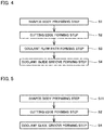
- Fig. 4 is a flowchart showing the method for manufacturing the cutting insert according to the embodiment.
- the method for manufacturing the cutting insert according to the embodiment includes a shaped body preparing step S1, a cutting edge forming step S2, a coolant flow path forming step S3, and a coolant guide groove forming step S4.
- a shaped body is prepared, which is to serve as the cutting insert according to the embodiment by performing cutting edge forming step S2, coolant flow path forming step S3, and coolant guide groove forming step S4.
- the shaped body has a first portion and a second portion.
- the first portion is a portion to serve as cutting edge tip 10 by performing cutting edge forming step S2, coolant flow path forming step S3, and coolant guide groove forming step S4.
- the second portion is a portion to serve as substrate 20 by performing cutting edge forming step S2, coolant flow path forming step S3, and coolant guide groove forming step S4.
- the first portion is prepared by sintering CBN powder, PCD powder or the like.
- the second portion is prepared by sintering a mixture of WC (tungsten carbide) and a binder such as Co (cobalt).
- the shaped body is obtained by fixing the first portion and the second portion to each other by way of brazing or the like.
- cutting edge forming step S2 rake face 1 and flank face 2 are formed at surfaces of the shaped body prepared in shaped body preparing step S1. As a result, cutting edge 3 is formed in cutting edge forming step S2. In cutting edge forming step S2, rake face 1, flank face 2, and cutting edge 3 are formed by polishing the surfaces of the shaped body, for example.
- coolant flow path 4 is formed inside the shaped body prepared in shaped body preparing step S1.
- coolant flow path 4 is formed by drilling the shaped body, for example.
- coolant guide groove 5 is formed in the shaped body prepared in shaped body preparing step S1. Coolant guide groove 5 is formed by emitting laser to flank face 2 (or the surface of the shaped body to serve as flank face 2 by performing cutting edge forming step S2) so as to remove a portion of the shaped body, for example.
- cutting edge forming step S2, coolant flow path forming step S3, and coolant guide groove forming step S4 may be performed in any order.
- coolant guide groove forming step S4 may be performed after performing coolant flow path forming step S3, and then cutting edge forming step S2 may be performed.
- cutting edge forming step S2 may be performed after coolant flow path forming step S3, and then coolant guide groove forming step S4 may be performed.
- Fig. 5 is a flowchart showing another exemplary method for manufacturing the cutting insert according to the embodiment.
- the method for manufacturing the cutting insert according to the embodiment includes a shaped body preparing step S11, cutting edge forming step S2, and coolant guide groove forming step S4.
- shaped body preparing step S11 a shaped body having coolant flow path 4 provided therein is prepared.
- coolant flow path 4 may be formed simultaneously (the step of forming coolant flow path 4 may be included in the step of preparing the shaped body).
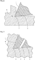
- Fig. 6 is a schematic view of cutting using the cutting insert according to the embodiment. As shown in Fig. 6 , a workpiece W and flank face 2 are in close contact with each other in the cutting using the cutting insert according to the embodiment. Therefore, coolant supplied from outside the cutting insert according to the embodiment is less likely to reach the vicinity of cutting edge 3.
- Fig. 7 is an enlarged view of a region VII in Fig. 6 .
- coolant guide groove 5 is provided in flank face 2. Since flank face 2 is depressed at coolant guide groove 5, there is a space between workpiece W and coolant guide groove 5 even when flank face 2 and workpiece W are in close contact with each other.
- coolant guide groove 5 is connected to coolant flow path 4 in flank face 2.
- coolant guide groove 5 extends from coolant flow path 4 toward cutting edge 3. Therefore, in the cutting insert according to the embodiment, the coolant flowing through coolant flow path 4 is more securely supplied to the vicinity of cutting edge 3 via the space defined by workpiece W and coolant guide groove 5.
- the thickness of the cutting insert according to the embodiment is decreased, thus resulting in decreased strength. Since cutting force is applied to the vicinity of the cutting edge during cutting, the strength in the vicinity of the cutting edge has a large influence over durability of the cutting insert.
- the strength of the cutting insert at the side close to cutting edge 3 can be suppressed from being decreased.
- the coolant is pushed out from coolant guide groove 5 toward cutting edge 3. Therefore, in this case, the coolant can be more securely supplied to the vicinity of cutting edge 3 while suppressing the decrease in strength of the cutting insert in the vicinity of the cutting edge.
- the coolant may become less likely to enter coolant guide groove 5 due to surface tension of the coolant.
- depth D is more than or equal to 0.2 mm and less than or equal to 2.0 mm, the coolant can be suppressed from being less likely to enter coolant guide groove 5 due to an influence of the surface tension of the coolant.
- coolant flow path 4 when coolant flow path 4 is provided in flank face 2 and is inclined to attain a smaller distance between coolant flow path 4 and cutting edge 3, the coolant flowing through coolant flow path 4 is facilitated to flow into between workpiece W and coolant guide groove 5 during the cutting. Therefore, in this case, the coolant is facilitated to be supplied more securely to the vicinity of cutting edge 3.
Landscapes
- Engineering & Computer Science (AREA)
- Mechanical Engineering (AREA)
- Cutting Tools, Boring Holders, And Turrets (AREA)
- Auxiliary Devices For Machine Tools (AREA)
Abstract
Description
- The present disclosure relates to a cutting insert and a method for manufacturing the cutting insert. The present application claims a priority based on Japanese Patent Application No.
2017-140115 filed on July 19, 2017 - Conventionally, a cutting insert described in Japanese Patent Laying-Open No.
2016-190275 Patent Literature 1, a coolant holding portion is formed. The coolant holding portion is constituted of a plurality of grooves and a plurality of ribs formed in the flank face. - The cutting insert described in
Patent Literature 1 is attached to a tool body. Inside the tool body, a path for supplying the coolant is formed. This path opens in a surface of the tool body, thereby forming a coolant supply hole. Part of coolant sent out from the coolant supply hole is ejected onto the flank face of the cutting insert described inPatent Literature 1, and is accordingly supplied to the coolant holding portion. - PTL 1: Japanese Patent Laying-Open No.
2016-190275 - A cutting insert according to one embodiment of the present disclosure includes: a rake face; a flank face continuous to the rake face; and a cutting edge constituted of a ridgeline between the rake face and the flank face. A coolant flow path is provided inside the cutting insert. One end portion of the coolant flow path opens in the flank face to form a coolant ejection hole. The flank face is provided with a coolant guide groove extending from the coolant ejection hole toward the cutting edge with a base end portion of the coolant guide groove being connected to the coolant ejection hole and with a front end portion of the coolant guide groove being disposed at a position close to the cutting edge relative to the base end portion.
- A method for manufacturing a cutting insert according to one embodiment of the present disclosure is a method for manufacturing the above-described cutting insert. The method for manufacturing the cutting insert according to one embodiment of the present disclosure includes: preparing a shaped body for the cutting insert; forming the rake face, the flank face, and the cutting edge in the shaped body; forming the coolant flow path inside the shaped body and forming the coolant ejection hole in the flank face; and forming the coolant guide groove in the flank face.
-
-
Fig. 1 is a perspective view of a cutting insert according to an embodiment. -
Fig. 2 is a cross sectional view along II-II inFig. 1 . -
Fig. 3 is a cross sectional view along III-III inFig. 1 . -
Fig. 4 is a flowchart showing a method for manufacturing the cutting insert according to the embodiment. -
Fig. 5 is a flowchart showing another exemplary method for manufacturing the cutting insert according to the embodiment. -
Fig. 6 is a schematic view of cutting using the cutting insert according to the embodiment. -
Fig. 7 is an enlarged view of a region VII inFig. 6 . - In the cutting insert described in
Patent Literature 1, the coolant supply hole that opens in the surface of the tool body is disposed at a position away from the coolant holding portion formed in the cutting insert. Particularly, when a plate is disposed between the cutting insert and the tool body, the coolant supply hole is further away from the coolant holding portion. Moreover, when cutting a workpiece using the cutting insert described inPatent Literature 1, the flank face of the cutting insert and the workpiece are in close contact with each other or a space therebetween is very small. Therefore, in the cutting tool described inPatent Literature 1, most of the coolant sent out from the coolant supply hole is blocked by the workpiece, and very small part of the coolant is actually supplied to the coolant holding portion. As a result, in the cutting insert described inPatent Literature 1, there is still room for improvement in order to sufficiently cool and lubricate the cutting edge. - The present disclosure has been made in view of the above-described problem of the conventional art. More specifically, the present disclosure provides: a cutting insert in which coolant can be supplied to a vicinity of a cutting edge more securely than in the conventional art; and a method for manufacturing such a cutting insert.
- According to the cutting insert according to one embodiment of the present disclosure, coolant can be supplied to the vicinity of the cutting edge more securely. According to the method for manufacturing the cutting insert according to one embodiment of the present disclosure, there can be obtained a cutting insert in which coolant can be supplied to the vicinity of the cutting edge more securely.
- First, embodiments of the present disclosure are listed and described.
- (1) A cutting insert according to one embodiment of the present disclosure includes: a rake face; a flank face continuous to the rake face; and a cutting edge constituted of a ridgeline between the rake face and the flank face. A coolant flow path is provided inside the cutting insert. One end portion of the coolant flow path opens in the flank face to form a coolant ejection hole. The flank face is provided with a coolant guide groove extending from the coolant ejection hole toward the cutting edge with a base end portion of the coolant guide groove being connected to the coolant ejection hole and with a front end portion of the coolant guide groove being disposed at a position close to the cutting edge relative to the base end portion.
- In the cutting insert according to (1), even when the flank face and the workpiece are in close contact with each other, a path through which the coolant flows is secured between the coolant guide groove and the workpiece. Therefore, in the cutting insert according to (1), the coolant can be more securely supplied to a vicinity of the cutting edge.
- (2) In the cutting insert according to (1), a cross sectional area of the coolant guide groove in a cross section parallel to the rake face may become smaller from the base end portion toward the front end portion.
- In the cutting insert according to (2), the cross sectional area of the coolant guide groove is small at the cutting edge side, thereby suppressing a decrease in strength of the cutting insert in the vicinity of the cutting edge. In the cutting insert according to (2), as the cross sectional area of the coolant guide groove becomes smaller, the coolant is pushed out to the vicinity of the cutting edge. Therefore, according to the cutting insert according to (2), the coolant can be more securely supplied to the vicinity of the cutting edge while suppressing the decrease in strength of the cutting insert in the vicinity of the cutting edge.
- (3) In the cutting insert according to (1), the coolant guide groove may have a depth of more than or equal to 0.2 mm and less than or equal to 2 mm.
- According to the cutting insert according to (3), the coolant can be suppressed from being less likely to enter the coolant guide groove due to an influence of surface tension of the coolant.
- (4) A method for manufacturing a cutting insert according to one embodiment of the present disclosure is a method for manufacturing the above-described cutting insert. The method for manufacturing the cutting insert according to one embodiment of the present disclosure includes: preparing a shaped body for the cutting insert; forming the rake face, the flank face, and the cutting edge in the shaped body; forming the coolant flow path inside the shaped body and forming the coolant ejection hole in the flank face; and forming the coolant guide groove in the flank face.
- According to the method for manufacturing the cutting insert according to (4), there can be obtained a cutting insert in which the coolant can be more securely supplied in the vicinity of the cutting edge.
- Next, embodiments of the present disclosure will be described with reference to figures. It should be noted that the same or corresponding portions in the figures are given the same reference characters. Moreover, at least parts of the embodiments described below may be appropriately combined.
- The following describes a configuration of a cutting insert according to an embodiment.
-
Fig. 1 is a perspective view of the cutting insert according to the embodiment. As shown inFig. 1 , the cutting insert according to the embodiment has arake face 1, aflank face 2, and acutting edge 3.Flank face 2 is continuous to rakeface 1. Cuttingedge 3 is constituted of a ridgeline betweenrake face 1 andflank face 2. - The cutting insert according to the embodiment has a
cutting edge tip 10 and asubstrate 20. Cuttingedge tip 10 is composed of CBN (cubic boron nitride), PCD (polycrystal diamond), or the like, for example.Substrate 20 is composed of cemented carbide, for example. Cuttingedge 3 is formed at cuttingedge tip 10. The cutting insert according to the embodiment may be constituted only ofsubstrate 20. It should be noted that in this case, a below-describedattachment portion 20d is not provided insubstrate 20, and cuttingedge 3 is formed insubstrate 20. -
Substrate 20 has atop surface 20a, abackside surface 20b, and aside surface 20c.Backside surface 20b is a surface opposite totop surface 20a.Side surface 20c is continuous totop surface 20a andbackside surface 20b.Top surface 20a is a surface to serve asrake face 1.Side surface 20c is a surface to serve asflank face 2. -
Top surface 20a is provided withattachment portion 20d.Attachment portion 20d is disposed at a nose curvature portion ofsubstrate 20. Intop surface 20a, a level difference in a direction fromtop surface 20a towardbackside surface 20b is provided atattachment portion 20d. Cuttingedge tip 10 is attached toattachment portion 20d. Cuttingedge tip 10 is attached toattachment portion 20d by way of brazing, for example. -
Fig. 2 is a cross sectional view along II-II inFig. 1 . As shown inFig. 2 , acoolant flow path 4 is provided inside the cutting insert according to the embodiment.Coolant flow path 4 is connected toflank face 2. From another viewpoint, it is said that one end portion ofcoolant flow path 4 opens inflank face 2 to form acoolant ejection hole 4a. Coolant flows incoolant flow path 4.Coolant flow path 4 is preferably inclined such that a distance betweencoolant flow path 4 andcutting edge 3 becomes smaller ascoolant flow path 4 is closer toflank face 2. - As shown in
Fig. 1 , acoolant guide groove 5 is provided inflank face 2.Coolant guide groove 5 is connected tocoolant flow path 4 inflank face 2. That is, asecond end 5b (base end portion) ofcoolant guide groove 5 is connected tocoolant ejection hole 4a.Coolant guide groove 5 extends fromcoolant flow path 4 toward cuttingedge 3. That is, afirst end 5a (front end portion) ofcoolant guide groove 5 is disposed at a position close to cuttingedge 3 relative tosecond end 5b. One or a plurality ofcoolant guide grooves 5 may be provided. -
Fig. 3 is a cross sectional view along III-III inFig. 1 . III-III represents a cross section parallel to rakeface 1. As shown inFig. 2 ,flank face 2 is depressed atcoolant guide groove 5.Coolant guide groove 5 has a cross sectional area A. Cross sectional area A is a cross sectional area ofcoolant guide groove 5 in the cross section parallel to rakeface 1. Cross sectional area A is an area of a portion surrounded, in the cross section parallel to rakeface 1, by a wall surface ofcoolant guide groove 5 and a straight line that connects the both ends ofcoolant guide groove 5. - Cross sectional area A of
coolant guide groove 5 preferably becomes smaller from thecoolant flow path 4 side toward thecutting edge 3 side (from thesecond end 5b side toward thefirst end 5a side).Coolant guide groove 5 has a curved cross sectional shape in the cross section parallel to rakeface 1, for example. It should be noted that the cross sectional shape ofcoolant guide groove 5 in the cross section parallel to rakeface 1 is not limited to this.Coolant guide groove 5 in the cross section parallel to rakeface 1 may have a rectangular cross sectional shape, for example. -
Coolant guide groove 5 has a depth D. Depth D is a distance between the bottom ofcoolant guide groove 5 and the straight line that connects the both ends ofcoolant guide groove 5 in the cross section parallel to rakeface 1. Depth D is preferably more than or equal to 0.2 mm and less than or equal to 2.0 mm. - As shown in
Fig. 1 ,coolant guide groove 5 hasfirst end 5a andsecond end 5b.First end 5a is an end at thecutting edge 3 side.Second end 5b is an end at a side opposite tofirst end 5a. That is,second end 5b is an end at thecoolant flow path 4 side.First end 5a is disposed to be separated from cuttingedge 3 by a distance L. Distance L is a distance betweencutting edge 3 andfirst end 5a in a direction orthogonal to cuttingedge 3. Preferably, distance L is more than or equal to 0.3 mm and less than or equal to 1.5 mm. Distance L is more preferably more than or equal to 0.3 mm and less than or equal to 1.0 mm.Coolant guide groove 5 preferably extends such thatfirst end 5a reaches cuttingedge tip 10. - The following describes a method for manufacturing the cutting insert according to the embodiment.
-
Fig. 4 is a flowchart showing the method for manufacturing the cutting insert according to the embodiment. As shown inFig. 4 , the method for manufacturing the cutting insert according to the embodiment includes a shaped body preparing step S1, a cutting edge forming step S2, a coolant flow path forming step S3, and a coolant guide groove forming step S4. - In shaped body preparing step S1, a shaped body is prepared, which is to serve as the cutting insert according to the embodiment by performing cutting edge forming step S2, coolant flow path forming step S3, and coolant guide groove forming step S4. The shaped body has a first portion and a second portion. The first portion is a portion to serve as cutting
edge tip 10 by performing cutting edge forming step S2, coolant flow path forming step S3, and coolant guide groove forming step S4. The second portion is a portion to serve assubstrate 20 by performing cutting edge forming step S2, coolant flow path forming step S3, and coolant guide groove forming step S4. The first portion is prepared by sintering CBN powder, PCD powder or the like. The second portion is prepared by sintering a mixture of WC (tungsten carbide) and a binder such as Co (cobalt). The shaped body is obtained by fixing the first portion and the second portion to each other by way of brazing or the like. - In cutting edge forming step S2, rake
face 1 andflank face 2 are formed at surfaces of the shaped body prepared in shaped body preparing step S1. As a result, cuttingedge 3 is formed in cutting edge forming step S2. In cutting edge forming step S2, rakeface 1,flank face 2, and cuttingedge 3 are formed by polishing the surfaces of the shaped body, for example. - In coolant flow path forming step S3,
coolant flow path 4 is formed inside the shaped body prepared in shaped body preparing step S1. In coolant flow path forming step S3,coolant flow path 4 is formed by drilling the shaped body, for example. - In coolant guide groove forming step S4,
coolant guide groove 5 is formed in the shaped body prepared in shaped body preparing step S1.Coolant guide groove 5 is formed by emitting laser to flank face 2 (or the surface of the shaped body to serve asflank face 2 by performing cutting edge forming step S2) so as to remove a portion of the shaped body, for example. - In the description above, cutting edge forming step S2, coolant flow path forming step S3, and coolant guide groove forming step S4 may be performed in any order. For example, coolant guide groove forming step S4 may be performed after performing coolant flow path forming step S3, and then cutting edge forming step S2 may be performed. Alternatively, cutting edge forming step S2 may be performed after coolant flow path forming step S3, and then coolant guide groove forming step S4 may be performed.
-
Fig. 5 is a flowchart showing another exemplary method for manufacturing the cutting insert according to the embodiment. As shown inFig. 5 , the method for manufacturing the cutting insert according to the embodiment includes a shaped body preparing step S11, cutting edge forming step S2, and coolant guide groove forming step S4. In shaped body preparing step S11, a shaped body havingcoolant flow path 4 provided therein is prepared. In other words, when preparing the shaped body,coolant flow path 4 may be formed simultaneously (the step of formingcoolant flow path 4 may be included in the step of preparing the shaped body). - The following describes an effect of the cutting insert according to the embodiment.
-
Fig. 6 is a schematic view of cutting using the cutting insert according to the embodiment. As shown inFig. 6 , a workpiece W andflank face 2 are in close contact with each other in the cutting using the cutting insert according to the embodiment. Therefore, coolant supplied from outside the cutting insert according to the embodiment is less likely to reach the vicinity of cuttingedge 3. -
Fig. 7 is an enlarged view of a region VII inFig. 6 . As shown inFig. 6 , in the cutting insert according to the embodiment,coolant guide groove 5 is provided inflank face 2. Sinceflank face 2 is depressed atcoolant guide groove 5, there is a space between workpiece W andcoolant guide groove 5 even whenflank face 2 and workpiece W are in close contact with each other. As described above,coolant guide groove 5 is connected tocoolant flow path 4 inflank face 2. Moreover, as described above,coolant guide groove 5 extends fromcoolant flow path 4 toward cuttingedge 3. Therefore, in the cutting insert according to the embodiment, the coolant flowing throughcoolant flow path 4 is more securely supplied to the vicinity of cuttingedge 3 via the space defined by workpiece W andcoolant guide groove 5. - In the portion in which
coolant guide groove 5 is formed, the thickness of the cutting insert according to the embodiment is decreased, thus resulting in decreased strength. Since cutting force is applied to the vicinity of the cutting edge during cutting, the strength in the vicinity of the cutting edge has a large influence over durability of the cutting insert. - In the cutting insert according to the embodiment, when cross sectional area A becomes smaller from the
coolant flow path 4 side toward thecutting edge 3 side, the strength of the cutting insert at the side close to cuttingedge 3 can be suppressed from being decreased. Moreover, in this case, as cross sectional area A becomes smaller, the coolant is pushed out fromcoolant guide groove 5 toward cuttingedge 3. Therefore, in this case, the coolant can be more securely supplied to the vicinity of cuttingedge 3 while suppressing the decrease in strength of the cutting insert in the vicinity of the cutting edge. - When the depth of
coolant guide groove 5 is too small, the coolant may become less likely to entercoolant guide groove 5 due to surface tension of the coolant. In the cutting insert according to the embodiment, when depth D is more than or equal to 0.2 mm and less than or equal to 2.0 mm, the coolant can be suppressed from being less likely to entercoolant guide groove 5 due to an influence of the surface tension of the coolant. - In the cutting tool according to the embodiment, when
coolant flow path 4 is provided inflank face 2 and is inclined to attain a smaller distance betweencoolant flow path 4 andcutting edge 3, the coolant flowing throughcoolant flow path 4 is facilitated to flow into between workpiece W andcoolant guide groove 5 during the cutting. Therefore, in this case, the coolant is facilitated to be supplied more securely to the vicinity of cuttingedge 3. - The embodiments disclosed herein are illustrative and non-restrictive in any respect. The scope of the present invention is defined by the terms of the claims, rather than the embodiments described above, and is intended to include any modifications within the scope and meaning equivalent to the terms of the claims.
- 1: rake face; 2: flank face; 3: cutting edge; 4: coolant flow path; 4a: coolant ejection hole; 5: coolant guide groove; 5a: first end; 5b: second end; 10: cutting edge tip; 20: substrate; 20a: top surface; 20b: backside surface; 20c: side surface; 20d: attachment portion; A: cross sectional area; D: depth; L: distance; S1: shaped body preparing step; S11: shaped body preparing step; S2: cutting edge forming step; S3: coolant flow path forming step; S4: coolant guide groove forming step; W: workpiece.
Claims (4)
- A cutting insert comprising: a rake face; a flank face continuous to the rake face; and a cutting edge constituted of a ridgeline between the rake face and the flank face, wherein
a coolant flow path is provided inside the cutting insert,
one end portion of the coolant flow path opens in the flank face to form a coolant ejection hole, and
the flank face is provided with a coolant guide groove extending from the coolant ejection hole toward the cutting edge with a base end portion of the coolant guide groove being connected to the coolant ejection hole and with a front end portion of the coolant guide groove being disposed at a position close to the cutting edge relative to the base end portion. - The cutting insert according to claim 1, wherein a cross sectional area of the coolant guide groove in a cross section parallel to the rake face becomes smaller from the base end portion toward the front end portion.
- The cutting insert according to claim 1, wherein the coolant guide groove has a depth of more than or equal to 0.2 mm and less than or equal to 2 mm.
- A method for manufacturing the cutting insert recited in any one of claim 1 to claim 3, the method comprising:preparing a shaped body for the cutting insert;forming the rake face, the flank face, and the cutting edge in the shaped body;forming the coolant flow path inside the shaped body and forming the coolant ejection hole in the flank face; andforming the coolant guide groove in the flank face.
Applications Claiming Priority (2)
| Application Number | Priority Date | Filing Date | Title |
|---|---|---|---|
| JP2017140115 | 2017-07-19 | ||
| PCT/JP2018/019311 WO2019017064A1 (en) | 2017-07-19 | 2018-05-18 | Cutting insert and method for manufacturing cutting insert |
Publications (2)
| Publication Number | Publication Date |
|---|---|
| EP3656493A1 true EP3656493A1 (en) | 2020-05-27 |
| EP3656493A4 EP3656493A4 (en) | 2021-04-28 |
Family
ID=65015717
Family Applications (1)
| Application Number | Title | Priority Date | Filing Date |
|---|---|---|---|
| EP18834652.2A Pending EP3656493A4 (en) | 2017-07-19 | 2018-05-18 | CUTTING INSERT AND CUTTING INSERT MANUFACTURING PROCESS |
Country Status (6)
| Country | Link |
|---|---|
| US (1) | US11554427B2 (en) |
| EP (1) | EP3656493A4 (en) |
| JP (1) | JP7131750B2 (en) |
| KR (1) | KR20200016364A (en) |
| CN (1) | CN110891720A (en) |
| WO (1) | WO2019017064A1 (en) |
Cited By (1)
| Publication number | Priority date | Publication date | Assignee | Title |
|---|---|---|---|---|
| CZ309280B6 (en) * | 2021-03-30 | 2022-07-13 | Západočeská Univerzita V Plzni | Turning tool |
Families Citing this family (13)
| Publication number | Priority date | Publication date | Assignee | Title |
|---|---|---|---|---|
| JP2018027605A (en) * | 2016-08-19 | 2018-02-22 | 住友電工ハードメタル株式会社 | Cutting plate and cutting tool |
| KR20180088637A (en) * | 2016-12-20 | 2018-08-06 | 스미또모 덴꼬오 하드메탈 가부시끼가이샤 | Cutting tool and manufacturing method thereof |
| JP6651136B2 (en) * | 2017-10-25 | 2020-02-19 | 株式会社タンガロイ | Cutting inserts, deposits and holders |
| JP7418960B2 (en) * | 2019-02-08 | 2024-01-22 | 国立大学法人東海国立大学機構 | Cutting inserts and cutting tools |
| EP4008474B1 (en) * | 2019-08-01 | 2024-07-17 | Sumitomo Electric Hardmetal Corp. | Method for manufacturing a cutting tool, and the cutting tool |
| EP3858522A1 (en) * | 2020-01-31 | 2021-08-04 | Seco Tools Ab | A cutting insert for a cutting tool |
| US11590587B2 (en) | 2020-04-16 | 2023-02-28 | Allied Machine & Engineering Corporation | Drill systems with coolant delivery arrangements and methods |
| EP3919211A1 (en) * | 2020-06-02 | 2021-12-08 | Ceratizit Luxembourg Sàrl | Milling tool, use thereof and milling process |
| EP4035808A1 (en) * | 2021-02-01 | 2022-08-03 | KOMET Deutschland GmbH | Cutting element and cutting tool |
| JP7040657B1 (en) * | 2021-03-10 | 2022-03-23 | 株式会社タンガロイ | Cutting inserts and turning tools |
| KR20260028766A (en) * | 2023-06-21 | 2026-03-04 | 노 스크류 엘티디. | Cutting inserts with cooling channel features |
| JP1771199S (en) * | 2023-09-08 | 2024-05-23 | Cutting Tool Inserts | |
| JP1771198S (en) * | 2023-09-08 | 2024-05-23 | Cutting Tool Inserts |
Family Cites Families (16)
| Publication number | Priority date | Publication date | Assignee | Title |
|---|---|---|---|---|
| DE504275C (en) * | 1926-12-14 | 1930-08-04 | Alexander Jgnatieff | Heat dissipation device on tools |
| US4535216A (en) * | 1983-10-14 | 1985-08-13 | Rockwell International Corporation | Metal-working tool using electrical heating |
| US5775854A (en) | 1991-09-27 | 1998-07-07 | Iscar Ltd. | Metal cutting tool |
| IL99584A (en) * | 1991-09-27 | 1996-08-04 | Iscar Ltd | Metal cutting tool |
| JPH05301104A (en) * | 1992-04-28 | 1993-11-16 | Sumitomo Electric Ind Ltd | Indexable insert, its manufacturing method, and cutting tool |
| JP2001198708A (en) | 2000-01-11 | 2001-07-24 | Fuji Mach Mfg Co Ltd | Cutting tool and cutting method |
| JP2003266207A (en) * | 2002-03-14 | 2003-09-24 | Ngk Spark Plug Co Ltd | Part-Time Job |
| JP4830377B2 (en) | 2005-07-11 | 2011-12-07 | コニカミノルタオプト株式会社 | Cutting tools |
| JP4959395B2 (en) * | 2007-03-27 | 2012-06-20 | 京セラ株式会社 | Throw-away insert, turning tool equipped with the insert, and cutting method |
| JP2010179412A (en) * | 2009-02-05 | 2010-08-19 | Jtekt Corp | Cutting tool and cutting method |
| US8439609B2 (en) * | 2010-10-04 | 2013-05-14 | Michigan Technological University | Micro-jet cooling of cutting tools |
| JP5743272B2 (en) * | 2011-08-30 | 2015-07-01 | 住友電工ハードメタル株式会社 | Ultra-high pressure sintered tool with flank internal oil hole |
| CN203751361U (en) * | 2014-04-10 | 2014-08-06 | 哈尔滨汽轮机厂有限责任公司 | Turning tool for turning cooled through cold air |
| US9895755B2 (en) | 2014-12-09 | 2018-02-20 | Kennametal Inc. | Cutting insert with internal coolant passages and method of making same |
| JP2016190275A (en) | 2015-03-30 | 2016-11-10 | 国立大学法人 東京大学 | Cutting insert and cutting edge exchangeable tool |
| JP2017140115A (en) | 2016-02-08 | 2017-08-17 | テルモ株式会社 | Spine treatment method, and catheter for spine treatment |
-
2018
- 2018-05-18 CN CN201880047398.0A patent/CN110891720A/en active Pending
- 2018-05-18 WO PCT/JP2018/019311 patent/WO2019017064A1/en not_active Ceased
- 2018-05-18 JP JP2019530902A patent/JP7131750B2/en active Active
- 2018-05-18 US US16/631,267 patent/US11554427B2/en active Active
- 2018-05-18 EP EP18834652.2A patent/EP3656493A4/en active Pending
- 2018-05-18 KR KR1020207000575A patent/KR20200016364A/en not_active Ceased
Cited By (1)
| Publication number | Priority date | Publication date | Assignee | Title |
|---|---|---|---|---|
| CZ309280B6 (en) * | 2021-03-30 | 2022-07-13 | Západočeská Univerzita V Plzni | Turning tool |
Also Published As
| Publication number | Publication date |
|---|---|
| US11554427B2 (en) | 2023-01-17 |
| US20200215618A1 (en) | 2020-07-09 |
| KR20200016364A (en) | 2020-02-14 |
| EP3656493A4 (en) | 2021-04-28 |
| JPWO2019017064A1 (en) | 2020-05-28 |
| JP7131750B2 (en) | 2022-09-06 |
| CN110891720A (en) | 2020-03-17 |
| WO2019017064A1 (en) | 2019-01-24 |
Similar Documents
| Publication | Publication Date | Title |
|---|---|---|
| US11554427B2 (en) | Cutting insert and method for manufacturing cutting insert | |
| CN110891719B (en) | Cutting tool holder | |
| CN101218052B (en) | A cutting insert for turning and a chip breaking device with space for cooling jets | |
| JP5587345B2 (en) | Cutting tool with retractable nozzle | |
| KR101292864B1 (en) | A milling cutter and an indexable cutting insert | |
| CN101094741B (en) | Cutting inserts with cutting end anchor portion | |
| US10071428B2 (en) | Holder, cutting tool, and method of producing machined product | |
| JP2010516482A5 (en) | ||
| JP2013107196A (en) | Cutting assembly with enhanced coolant delivery | |
| EP3593929B1 (en) | Cutting insert and milling tool | |
| JP6011747B1 (en) | Cutting tools | |
| CN113316494A (en) | Cutting tool | |
| CN103402677A (en) | Guide pad, cutting tool body, and cutting tool | |
| US11806792B2 (en) | Cutting tool and method for manufacturing machined product | |
| JP5501598B2 (en) | Holder, cutting tool using the same, and cutting method using the same | |
| JP2014018891A (en) | Cutting insert | |
| JP2019018294A (en) | Cutting insert | |
| EP4169642A1 (en) | Coolant supply mechanism | |
| US20190270150A1 (en) | Cutting tool and method of manufacturing machined product | |
| US11458546B2 (en) | Throwaway insert | |
| JP2007044834A (en) | Insert tool, insert, and insert holder | |
| EP3858522A1 (en) | A cutting insert for a cutting tool | |
| JP7344376B2 (en) | Manufacturing method for cutting inserts, cutting tools and cut products | |
| EP4327969A1 (en) | Tip and cutting tool | |
| JP6418765B2 (en) | Cutting insert, cutting tool, and method of manufacturing cut workpiece |
Legal Events
| Date | Code | Title | Description |
|---|---|---|---|
| STAA | Information on the status of an ep patent application or granted ep patent |
Free format text: STATUS: THE INTERNATIONAL PUBLICATION HAS BEEN MADE |
|
| PUAI | Public reference made under article 153(3) epc to a published international application that has entered the european phase |
Free format text: ORIGINAL CODE: 0009012 |
|
| STAA | Information on the status of an ep patent application or granted ep patent |
Free format text: STATUS: REQUEST FOR EXAMINATION WAS MADE |
|
| 17P | Request for examination filed |
Effective date: 20200117 |
|
| AK | Designated contracting states |
Kind code of ref document: A1 Designated state(s): AL AT BE BG CH CY CZ DE DK EE ES FI FR GB GR HR HU IE IS IT LI LT LU LV MC MK MT NL NO PL PT RO RS SE SI SK SM TR |
|
| AX | Request for extension of the european patent |
Extension state: BA ME |
|
| DAV | Request for validation of the european patent (deleted) | ||
| DAX | Request for extension of the european patent (deleted) | ||
| A4 | Supplementary search report drawn up and despatched |
Effective date: 20210331 |
|
| RIC1 | Information provided on ipc code assigned before grant |
Ipc: B23B 27/10 20060101AFI20210325BHEP Ipc: B23B 27/14 20060101ALI20210325BHEP Ipc: B23P 15/28 20060101ALI20210325BHEP Ipc: B23B 27/16 20060101ALI20210325BHEP Ipc: B23C 5/28 20060101ALI20210325BHEP Ipc: B23C 5/20 20060101ALI20210325BHEP |
|
| STAA | Information on the status of an ep patent application or granted ep patent |
Free format text: STATUS: EXAMINATION IS IN PROGRESS |
|
| 17Q | First examination report despatched |
Effective date: 20230821 |