EP3656207B1 - Outdoor blower device, concentration attachment for outdoor blower device, and related method. - Google Patents
Outdoor blower device, concentration attachment for outdoor blower device, and related method. Download PDFInfo
- Publication number
- EP3656207B1 EP3656207B1 EP19211201.9A EP19211201A EP3656207B1 EP 3656207 B1 EP3656207 B1 EP 3656207B1 EP 19211201 A EP19211201 A EP 19211201A EP 3656207 B1 EP3656207 B1 EP 3656207B1
- Authority
- EP
- European Patent Office
- Prior art keywords
- air
- air tube
- concentrator
- guide surface
- blower device
- Prior art date
- Legal status (The legal status is an assumption and is not a legal conclusion. Google has not performed a legal analysis and makes no representation as to the accuracy of the status listed.)
- Active
Links
Images


Classifications
-
- A—HUMAN NECESSITIES
- A01—AGRICULTURE; FORESTRY; ANIMAL HUSBANDRY; HUNTING; TRAPPING; FISHING
- A01G—HORTICULTURE; CULTIVATION OF VEGETABLES, FLOWERS, RICE, FRUIT, VINES, HOPS OR SEAWEED; FORESTRY; WATERING
- A01G20/00—Cultivation of turf, lawn or the like; Apparatus or methods therefor
- A01G20/40—Apparatus for cleaning the lawn or grass surface
- A01G20/43—Apparatus for cleaning the lawn or grass surface for sweeping, collecting or disintegrating lawn debris
- A01G20/47—Vacuum or blower devices
-
- A—HUMAN NECESSITIES
- A47—FURNITURE; DOMESTIC ARTICLES OR APPLIANCES; COFFEE MILLS; SPICE MILLS; SUCTION CLEANERS IN GENERAL
- A47L—DOMESTIC WASHING OR CLEANING; SUCTION CLEANERS IN GENERAL
- A47L5/00—Structural features of suction cleaners
- A47L5/12—Structural features of suction cleaners with power-driven air-pumps or air-compressors, e.g. driven by motor vehicle engine vacuum
- A47L5/14—Structural features of suction cleaners with power-driven air-pumps or air-compressors, e.g. driven by motor vehicle engine vacuum cleaning by blowing-off, also combined with suction cleaning
-
- B—PERFORMING OPERATIONS; TRANSPORTING
- B05—SPRAYING OR ATOMISING IN GENERAL; APPLYING FLUENT MATERIALS TO SURFACES, IN GENERAL
- B05B—SPRAYING APPARATUS; ATOMISING APPARATUS; NOZZLES
- B05B1/00—Nozzles, spray heads or other outlets, with or without auxiliary devices such as valves, heating means
- B05B1/34—Nozzles, spray heads or other outlets, with or without auxiliary devices such as valves, heating means designed to influence the nature of flow of the liquid or other fluent material, e.g. to produce swirl
- B05B1/3402—Nozzles, spray heads or other outlets, with or without auxiliary devices such as valves, heating means designed to influence the nature of flow of the liquid or other fluent material, e.g. to produce swirl to avoid or reduce turbulence, e.g. with fluid flow straightening means
-
- E—FIXED CONSTRUCTIONS
- E01—CONSTRUCTION OF ROADS, RAILWAYS, OR BRIDGES
- E01H—STREET CLEANING; CLEANING OF PERMANENT WAYS; CLEANING BEACHES; DISPERSING OR PREVENTING FOG IN GENERAL CLEANING STREET OR RAILWAY FURNITURE OR TUNNEL WALLS
- E01H1/00—Removing undesirable matter from roads or like surfaces, with or without moistening of the surface
- E01H1/08—Pneumatically dislodging or taking-up undesirable matter or small objects; Drying by heat only or by streams of gas; Cleaning by projecting abrasive particles
- E01H1/0809—Loosening or dislodging by blowing ; Drying by means of gas streams
-
- F—MECHANICAL ENGINEERING; LIGHTING; HEATING; WEAPONS; BLASTING
- F04—POSITIVE - DISPLACEMENT MACHINES FOR LIQUIDS; PUMPS FOR LIQUIDS OR ELASTIC FLUIDS
- F04D—NON-POSITIVE-DISPLACEMENT PUMPS
- F04D29/00—Details, component parts, or accessories
- F04D29/40—Casings; Connections of working fluid
- F04D29/52—Casings; Connections of working fluid for axial pumps
- F04D29/54—Fluid-guiding means, e.g. diffusers
- F04D29/541—Specially adapted for elastic fluid pumps
- F04D29/542—Bladed diffusers
-
- A—HUMAN NECESSITIES
- A47—FURNITURE; DOMESTIC ARTICLES OR APPLIANCES; COFFEE MILLS; SPICE MILLS; SUCTION CLEANERS IN GENERAL
- A47L—DOMESTIC WASHING OR CLEANING; SUCTION CLEANERS IN GENERAL
- A47L9/00—Details or accessories of suction cleaners, e.g. mechanical means for controlling the suction or for effecting pulsating action; Storing devices specially adapted to suction cleaners or parts thereof; Carrying-vehicles specially adapted for suction cleaners
- A47L9/02—Nozzles
- A47L9/08—Nozzles with means adapted for blowing
-
- F—MECHANICAL ENGINEERING; LIGHTING; HEATING; WEAPONS; BLASTING
- F05—INDEXING SCHEMES RELATING TO ENGINES OR PUMPS IN VARIOUS SUBCLASSES OF CLASSES F01-F04
- F05B—INDEXING SCHEME RELATING TO WIND, SPRING, WEIGHT, INERTIA OR LIKE MOTORS, TO MACHINES OR ENGINES FOR LIQUIDS COVERED BY SUBCLASSES F03B, F03D AND F03G
- F05B2240/00—Components
- F05B2240/10—Stators
- F05B2240/12—Fluid guiding means, e.g. vanes
- F05B2240/123—Nozzles
Definitions
- the present invention is directed to outdoor blowers having an air tube with a concentrator to increase the air flow velocity.
- blower devices are used to clean patios, sidewalks and other areas by blowing away leaves and other debris.
- Currently known blowers can be axial-type or centrifugal-type, and can be powered by a variety of sources including DC electric power, AC electric power or petroleum based fuels.
- the blower must generate a sufficiently large quantity of air, having sufficient velocity. In some cases, air quantity is preferred over air velocity, and thus the user should be able to dictate this on the blower apparatus.
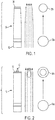
- FIG. 1 shows a typical air tube 30 for a blower having a concentrator feature built in.
- the air tube's cross-sectional area is gradually reduced from its proximal end 32 to its distal end 34, as shown by the circles 36a and 36b, respectively.
- the cross-sectional area is reduced by reducing the diameter of the air tube which defines the field of the jetting air or its area-of-effect (AoE).
- AoE area-of-effect
- US2016/0029863 A1 discloses an airflow guiding member arranged in an airflow guiding section inside an air duct.
- the present invention provides a concentrator nozzle that increases the airflow velocity without sacrificing its AoE.
- the concentrator nozzle is formed of an outer ring with a centrally located guide surface.
- the concentrator is placed at the exit of an air tube, where the guide surface blocks a central portion of the airflow.
- the outer diameter of the air tube is not changed, and in this way, air velocity is increased without affecting the AoE.
- the concentrator nozzle is shown as a separate attachment allowing the user to use it on existing air tubes.
- blower device According to a first aspect there is provided a blower device according to claim 1.
- the air guide surface is partially inside the air tube and partially outside the air tube.
- the concentrator may have an outer ring that is secured to the air tube.
- the air guide surface may be connected to the outer ring by vanes.
- the air guide surface may be centered with respect to the air tube.
- the air guide surface may be tear-drop shaped.
- the concentrator may be made of two pieces that are threadedly connected together.
- the two pieces may be an outer ring piece and an air guide surface piece.
- the guide surface may be tear-drop shaped.
- the outer ring and the guide surface may be made of separate pieces that are releasably connected together.
- the concentrator may be separate from the air tube, the method may further comprise the step of securing the concentrator to the end of the air tube prior to turning on the blower device.
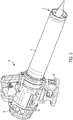
- a blower 10 incorporating a concentrator attachment 12 of the present invention is shown.
- the blower is an axial type blower with a main housing 14 having a rear air inlet 16 and an air tube 18.
- the concentrator attachment 12 is secured at an outlet of the air tube 18.
- a motor 20 and fan 22 (see Fig. 4 ) are positioned in the main housing 14, with the motor being powered by a battery 24.
- the battery 24 is secured to a bottom portion of the main housing 14 within a battery housing 26.
- the battery housing 26 surrounds the battery 24 and protects it from damage during falls or other mishaps. Additionally, the battery housing 26 is used to support the blower 10 when it's placed on the ground or other surface.
- any other power source such as AC power or gasoline, can be used to provide energy to the motor and still fall within the scope of the invention.
- the air tube 18 is connected to the housing 14 at a first end, using ribbed walls or other well-known connection means.
- the air tube 18 may be connected to a front portion of the housing 14.
- the air tube 18 maintains a constant cross-sectional area along its longitudinal length.
- the concentrator 12 includes an outer ring 40 and an inner guide surface 42.
- the guide surface 42 is connected to the ring by guide vanes 44.
- the outer ring 40 forms a U-shaped clip or coupling portion 46 that frictionally fits over the end of the air tube 18 to secure it in place.
- the concentrator 12 can be secured to the air tube 18 using a bayonet style connector as shown in Fig. 9 .
- the end of the air tube 18 includes a pin 70.
- the outer ring of the concentrator includes an L-shaped slot 72 that slides over the pin 70 and is rotated to lock the concentrator to the air tube.
- the concentrator 12 can also be threadingly connected to the air tube 18 or use any other known connection means.
- the vanes 44 are shown in the figures with a slight curve.
- the vanes 44 can be straight or any other configuration to modify the airflow, and can be used to help reduce turbulence.
- the guide surface 42 can be any desired aerodynamic shape, but is shown as tear-drop shaped and is placed at the exit of the air tube 18. As shown in Fig. 5 , part of the guide surface 42 is inside the air tube and part of it is outside. The guide surface 42 blocks a center portion of the airflow path so that air is diverted around the guide surface. Because the area of the airflow path area is reduced, the air velocity is increased. However, at the same time, the diameter of the air tube itself is not changed and so its AoE is not affected.
- FIG. 1 shows a typical air tube 30 having a concentrator feature built in.
- the tapered air tube's diameter is reduced so that its exit area and AoE are reduced by 39%, as shown by the cross-sectional area circles at its proximal end 36a and its distal end 36b.
- Fig. 2 which shows the air tube 18 of the present invention with a concentrator attachment 12 secured at its distal end 19.
- the diameter of the air tube 18 itself remains constant along its length so that the diameter at its exit 50b is the same as its proximal end 50b. In other words, there is no reduction in the AoE.
- the concentrator's guide surface 42 blocks the airflow at the air tube's exit, the cross-sectional area is reduced by 39% increasing the air velocity at the exit. It should be understood that although the present invention reduces the cross-sectional area by 39%, the guide surface 42 can be sized to reduce the cross-sectional area by more or less than this amount depending on the desired airflow profile.
- the guide surface 42 is shown centered at the exit of the air tube, the guide surface 42 can be off-center or at any position so long as it remains at the exit of the air tube and blocks some portion of the air path.
- the concentrator 12 can be used with any air tube, including straight air tubes like in the present invention, or tapered air tubes like that shown in Fig. 1 .
- the use of a concentrator with a tapered air tube would simply alter the existing airflow dynamics in a manner similar to the use of a concentrator with a straight air tube.
- the concentrator is shown here as a separate attachment, the principles disclosed here can be integrally formed in an air tube and still fall within the scope of the invention.
- the guide surface be positioned at the exit of the air tube 18. This ensures that the air speed upon exiting the air tube is maximized. Having the guide surface placed further upstream may briefly increase the air velocity, but the air velocity would again drop by the time it reached the air tube exit.
- the concentrator attachment 12 is made of two separate pieces as shown in Fig. 8 .
- a first piece is the head portion 60 which comprises an upstream part of the guide surface and a second piece is a tail portion 62 comprising the ring 40 and a downstream part of the guide surface.
- the two pieces have threaded connectors that are screwed together to produce the concentrator attachment.
- the concentrator attachment from two pieces simplifies manufacturing and assembly. It should be understood that threadingly connecting the two pieces is only one way of connecting the two pieces, and that the two pieces may be connected in any manner, including snap fit, adhesives, etc. Additionally, the concentrator attachment can be made from one piece if desired.
Landscapes
- Engineering & Computer Science (AREA)
- Life Sciences & Earth Sciences (AREA)
- Environmental Sciences (AREA)
- Mechanical Engineering (AREA)
- General Engineering & Computer Science (AREA)
- Physics & Mathematics (AREA)
- Fluid Mechanics (AREA)
- Architecture (AREA)
- Civil Engineering (AREA)
- Structural Engineering (AREA)
- Structures Of Non-Positive Displacement Pumps (AREA)
- Jet Pumps And Other Pumps (AREA)
Description
- The present invention is directed to outdoor blowers having an air tube with a concentrator to increase the air flow velocity.
- Outdoor blower devices are used to clean patios, sidewalks and other areas by blowing away leaves and other debris. Currently known blowers can be axial-type or centrifugal-type, and can be powered by a variety of sources including DC electric power, AC electric power or petroleum based fuels. To satisfy the requirements of the user, the blower must generate a sufficiently large quantity of air, having sufficient velocity. In some cases, air quantity is preferred over air velocity, and thus the user should be able to dictate this on the blower apparatus.
- Concentrator nozzles are well known and used to adjust the performance of the blower apparatus.
Fig. 1 shows atypical air tube 30 for a blower having a concentrator feature built in. In this embodiment, the air tube's cross-sectional area is gradually reduced from itsproximal end 32 to its distal end 34, as shown by thecircles US2016/0029863 A1 discloses an airflow guiding member arranged in an airflow guiding section inside an air duct. - Therefore, the present invention provides a concentrator nozzle that increases the airflow velocity without sacrificing its AoE. The concentrator nozzle is formed of an outer ring with a centrally located guide surface. The concentrator is placed at the exit of an air tube, where the guide surface blocks a central portion of the airflow. The outer diameter of the air tube is not changed, and in this way, air velocity is increased without affecting the AoE. In a preferred embodiment, the concentrator nozzle is shown as a separate attachment allowing the user to use it on existing air tubes.
- According to a first aspect there is provided a blower device according to claim 1.
- The air guide surface is partially inside the air tube and partially outside the air tube.
- The concentrator may have an outer ring that is secured to the air tube. The air guide surface may be connected to the outer ring by vanes. The air guide surface may be centered with respect to the air tube.
- The air guide surface may be tear-drop shaped.
- The concentrator may be made of two pieces that are threadedly connected together. The two pieces may be an outer ring piece and an air guide surface piece.
- According to a second aspect there is provided a concentrator attachment for a blower device, according to claim 8.
- The guide surface may be tear-drop shaped.
- The outer ring and the guide surface may be made of separate pieces that are releasably connected together.
- According to a third aspect there is provided a method of increasing the air velocity of a blower device, according to claim 11.
- The concentrator may be separate from the air tube, the method may further comprise the step of securing the concentrator to the end of the air tube prior to turning on the blower device.
- Further features and advantages of the present invention will be better understood by reference to the following description, which is given by way of example and in association with the accompanying drawings, in which:
-
Fig. 1 shows the airflow through a typical tapered air tube; -
Fig. 2 shows the airflow through an air tube with a concentrator attachment of the present invention; -
Fig. 3 is a blower with the concentrator attachment of the present invention; -
Fig. 4 is a side sectional view of the motor housing; -
Fig. 5 is a side sectional view at the outlet of the air tube; -
Fig. 6 is a perspective view of the concentrator attachment; -
Fig. 7 is a front view of the concentrator attachment; -
Fig. 8 shows the concentrator attachment in two pieces; and -
Fig. 9 shows an alternate embodiment of the connection between the concentrator attachment and the air tube. - Referring to
Fig. 3 , a blower 10 incorporating aconcentrator attachment 12 of the present invention is shown. The blower is an axial type blower with amain housing 14 having arear air inlet 16 and anair tube 18. Theconcentrator attachment 12 is secured at an outlet of theair tube 18. Amotor 20 and fan 22 (seeFig. 4 ) are positioned in themain housing 14, with the motor being powered by abattery 24. Thebattery 24 is secured to a bottom portion of themain housing 14 within abattery housing 26. Thebattery housing 26 surrounds thebattery 24 and protects it from damage during falls or other mishaps. Additionally, thebattery housing 26 is used to support the blower 10 when it's placed on the ground or other surface. - Although a
battery 24 is shown, any other power source, such as AC power or gasoline, can be used to provide energy to the motor and still fall within the scope of the invention. - The
air tube 18 is connected to thehousing 14 at a first end, using ribbed walls or other well-known connection means. Theair tube 18 may be connected to a front portion of thehousing 14. Theair tube 18 maintains a constant cross-sectional area along its longitudinal length. - As shown in
Figs. 5-7 , theconcentrator 12 includes anouter ring 40 and aninner guide surface 42. Theguide surface 42 is connected to the ring byguide vanes 44. As best shown inFig. 5 , theouter ring 40 forms a U-shaped clip orcoupling portion 46 that frictionally fits over the end of theair tube 18 to secure it in place. Alternatively, theconcentrator 12 can be secured to theair tube 18 using a bayonet style connector as shown inFig. 9 . Here the end of theair tube 18 includes apin 70. The outer ring of the concentrator includes an L-shaped slot 72 that slides over thepin 70 and is rotated to lock the concentrator to the air tube. Theconcentrator 12 can also be threadingly connected to theair tube 18 or use any other known connection means. - The
vanes 44 are shown in the figures with a slight curve. Thevanes 44 can be straight or any other configuration to modify the airflow, and can be used to help reduce turbulence. - The
guide surface 42, can be any desired aerodynamic shape, but is shown as tear-drop shaped and is placed at the exit of theair tube 18. As shown inFig. 5 , part of theguide surface 42 is inside the air tube and part of it is outside. The guide surface 42 blocks a center portion of the airflow path so that air is diverted around the guide surface. Because the area of the airflow path area is reduced, the air velocity is increased. However, at the same time, the diameter of the air tube itself is not changed and so its AoE is not affected. - This effect is best shown by reference to
Figs. 1 and 2. Fig. 1 shows atypical air tube 30 having a concentrator feature built in. The tapered air tube's diameter is reduced so that its exit area and AoE are reduced by 39%, as shown by the cross-sectional area circles at itsproximal end 36a and itsdistal end 36b. Contrast this withFig. 2 , which shows theair tube 18 of the present invention with aconcentrator attachment 12 secured at its distal end 19. The diameter of theair tube 18 itself remains constant along its length so that the diameter at itsexit 50b is the same as itsproximal end 50b. In other words, there is no reduction in the AoE. But because the concentrator'sguide surface 42 blocks the airflow at the air tube's exit, the cross-sectional area is reduced by 39% increasing the air velocity at the exit. It should be understood that although the present invention reduces the cross-sectional area by 39%, theguide surface 42 can be sized to reduce the cross-sectional area by more or less than this amount depending on the desired airflow profile. - Furthermore, although the
guide surface 42 is shown centered at the exit of the air tube, theguide surface 42 can be off-center or at any position so long as it remains at the exit of the air tube and blocks some portion of the air path. - It should be understood that the
concentrator 12 can be used with any air tube, including straight air tubes like in the present invention, or tapered air tubes like that shown inFig. 1 . The use of a concentrator with a tapered air tube would simply alter the existing airflow dynamics in a manner similar to the use of a concentrator with a straight air tube. Furthermore, although the concentrator is shown here as a separate attachment, the principles disclosed here can be integrally formed in an air tube and still fall within the scope of the invention. - Furthermore, it is important to note that the guide surface be positioned at the exit of the
air tube 18. This ensures that the air speed upon exiting the air tube is maximized. Having the guide surface placed further upstream may briefly increase the air velocity, but the air velocity would again drop by the time it reached the air tube exit. - In a preferred embodiment, the
concentrator attachment 12 is made of two separate pieces as shown inFig. 8 . A first piece is thehead portion 60 which comprises an upstream part of the guide surface and a second piece is atail portion 62 comprising thering 40 and a downstream part of the guide surface. The two pieces have threaded connectors that are screwed together to produce the concentrator attachment. - Producing the concentrator attachment from two pieces simplifies manufacturing and assembly. It should be understood that threadingly connecting the two pieces is only one way of connecting the two pieces, and that the two pieces may be connected in any manner, including snap fit, adhesives, etc. Additionally, the concentrator attachment can be made from one piece if desired.
Claims (12)
- An outdoor blower device (10) comprising:a housing (14) having a motor (20) and a fan (22) therein;an air tube (18) connected to a front portion of the housing; anda concentrator (12) connected at an end of the air tube, the concentrator positioning an air guide surface (42) within the air tube,characterised in that the air guide surface is partially inside the air tube and partially outside the air tube.
- The blower device of claim 1, wherein the concentrator has an outer ring (40) that is secured to the air tube.
- The blower device of claim 2, wherein the air guide surface is connected to the outer ring by vanes (44).
- The blower device of claim 2 or 3, wherein the air guide surface is centered with respect to the air tube.
- The blower device of any preceding claim, wherein the air guide surface is tear-drop shaped.
- The blower device of any preceding claim, wherein the concentrator is made of two pieces that are threadedly connected together.
- The blower device of claim 6, wherein the two pieces are an outer ring piece and an air guide surface piece.
- A concentrator attachment for an outdoor blower device, the concentrator attachment comprising:an outer ring adapted to be secured to an end of an air tube;a guide surface positioned within the outer ring and connected to the outer ring by vanes; andthe guide surface, when the outer ring is secured to the end of the air tube, is adapted to be at least partially within the air tube and partially outside the air tube.
- The concentrator attachment of claim 8, wherein the guide surface is tear-drop shaped.
- The concentrator attachment of claim 8, wherein the outer ring and the guide surface are made of separate pieces that are releasably connected together.
- A method of increasing air velocity of an outdoor blower device, comprising the steps of:providing a concentrator at an end of an air tube of a blower device, wherein the concentrator includes a guide surface within an air flow path, wherein the air guide surface is partially inside the air tube and partially outside the air tube; andturning on the blower device so that air is blown through the air tube, wherein prior to exiting the air tube the air is forced to move around the guide surface thus increasing its velocity.
- The method of increasing the air velocity of a blower device of claim 11, wherein the concentrator is separate from the air tube, further comprising the step of securing the concentrator to the end of the air tube prior to turning on the blower device.
Applications Claiming Priority (1)
| Application Number | Priority Date | Filing Date | Title |
|---|---|---|---|
| US16/200,017 US11523569B2 (en) | 2018-11-26 | 2018-11-26 | Concentrator attachment for blower air tube |
Publications (2)
| Publication Number | Publication Date |
|---|---|
| EP3656207A1 EP3656207A1 (en) | 2020-05-27 |
| EP3656207B1 true EP3656207B1 (en) | 2021-11-10 |
Family
ID=68655368
Family Applications (1)
| Application Number | Title | Priority Date | Filing Date |
|---|---|---|---|
| EP19211201.9A Active EP3656207B1 (en) | 2018-11-26 | 2019-11-25 | Outdoor blower device, concentration attachment for outdoor blower device, and related method. |
Country Status (2)
| Country | Link |
|---|---|
| US (3) | US11523569B2 (en) |
| EP (1) | EP3656207B1 (en) |
Families Citing this family (3)
| Publication number | Priority date | Publication date | Assignee | Title |
|---|---|---|---|---|
| US11523569B2 (en) * | 2018-11-26 | 2022-12-13 | Black & Decker, Inc. | Concentrator attachment for blower air tube |
| CN214737695U (en) * | 2020-09-29 | 2021-11-16 | 苏州宝时得电动工具有限公司 | Garden blower |
| EP4042861B1 (en) * | 2021-02-12 | 2023-12-20 | Andreas Stihl AG & Co. KG | Protection device for a suction or blowing channel of a working device and working device with a protective device |
Family Cites Families (23)
| Publication number | Priority date | Publication date | Assignee | Title |
|---|---|---|---|---|
| US4884314A (en) * | 1987-11-12 | 1989-12-05 | Black & Decker Inc. | Portable blower |
| US5473824A (en) * | 1994-03-21 | 1995-12-12 | Conair Corporation | Rotating outlet for hair dryers |
| US5555637A (en) * | 1994-10-14 | 1996-09-17 | Production Engineered Designs, Inc. | Drying apparatus |
| US5626156A (en) * | 1995-04-24 | 1997-05-06 | Vicory, Sr.; Gary L. | Hair styling system |
| US5950276A (en) * | 1998-03-03 | 1999-09-14 | Ryobi North America, Inc. | Blower and adjustable blower nozzle attachment |
| US6059541A (en) * | 1998-03-10 | 2000-05-09 | The Toro Company | Air inlet cover for portable blower/vacuum |
| US7841045B2 (en) * | 2007-08-06 | 2010-11-30 | Wd-40 Company | Hand-held high velocity air blower |
| EP2160954A1 (en) * | 2008-09-08 | 2010-03-10 | Koninklijke Philips Electronics N.V. | Hair dryer, an attachment for a hair dryer, and a hair dryer provided with such an attachment |
| JP5572060B2 (en) * | 2010-10-22 | 2014-08-13 | 株式会社やまびこ | Air blower |
| JP6065532B2 (en) | 2012-11-13 | 2017-01-25 | 日立工機株式会社 | Blower air duct |
| US9603497B2 (en) * | 2013-02-20 | 2017-03-28 | Chevron (Hk) Limited | Handheld blower |
| CN103420168B (en) | 2013-07-26 | 2016-06-08 | 莱芜市万祥矿业有限公司 | A kind of method utilizing Rotational wind generator to generate rotary wind |
| US9420924B2 (en) * | 2014-02-17 | 2016-08-23 | The Toro Company | Oscillating airstream nozzle for debris blower |
| JP6437745B2 (en) * | 2014-06-20 | 2018-12-12 | 株式会社マキタ | nozzle |
| DE202015103911U1 (en) * | 2014-08-01 | 2015-08-14 | Chervon Intellectual Property Limited | blowers |
| CN106714642A (en) * | 2014-09-15 | 2017-05-24 | 翼科技有限责任公司 | Portable electrically powered debris blower apparatus |
| US10227988B2 (en) * | 2014-11-28 | 2019-03-12 | Positec Power Tools (Suzhou) Co., Ltd. | Blower and a blowing vacuum device |
| CN204538894U (en) | 2015-03-20 | 2015-08-05 | 常州格力博有限公司 | Axial-flow blower motor preposition structure |
| US10670048B2 (en) * | 2015-05-28 | 2020-06-02 | Husqzarna AB | Blower with improved sound reduction |
| US9883726B2 (en) * | 2015-12-20 | 2018-02-06 | Shih-Ling Hsu | Hair dryer with improved outlet unit |
| US10729293B2 (en) * | 2017-02-15 | 2020-08-04 | The Toro Company | Debris blower incorporating flow ejector |
| US20200305360A1 (en) | 2017-09-29 | 2020-10-01 | Husqvarna Ab | An Adjustable Nozzle For a Blower |
| US11523569B2 (en) * | 2018-11-26 | 2022-12-13 | Black & Decker, Inc. | Concentrator attachment for blower air tube |
-
2018
- 2018-11-26 US US16/200,017 patent/US11523569B2/en active Active
-
2019
- 2019-11-25 EP EP19211201.9A patent/EP3656207B1/en active Active
-
2022
- 2022-11-15 US US17/987,162 patent/US11950543B2/en active Active
-
2024
- 2024-04-04 US US18/626,868 patent/US12490688B2/en active Active
Also Published As
| Publication number | Publication date |
|---|---|
| US11523569B2 (en) | 2022-12-13 |
| US20240245014A1 (en) | 2024-07-25 |
| EP3656207A1 (en) | 2020-05-27 |
| US20200163289A1 (en) | 2020-05-28 |
| US20230072366A1 (en) | 2023-03-09 |
| US12490688B2 (en) | 2025-12-09 |
| US11950543B2 (en) | 2024-04-09 |
Similar Documents
| Publication | Publication Date | Title |
|---|---|---|
| US12490688B2 (en) | Concentrator attachment for blower air tube | |
| US10405707B2 (en) | Blower | |
| CN102878058B (en) | fan | |
| CN106333459B (en) | Nozzle | |
| RU2586471C2 (en) | Manual device | |
| CN102878059B (en) | Fan | |
| US20130243588A1 (en) | Bladeless fan | |
| EP3225742A1 (en) | Air blower and blower/vacuum apparatus | |
| CN105736469B (en) | fan, fan volute and air conditioner | |
| CN104807124B (en) | Humidification and atomization device and floor fan with humidification and atomization device | |
| CN102878060B (en) | Fan | |
| RU2003133190A (en) | DIFFUSER WITH THE POSSIBILITY OF JET BLOW EXECUTIVE REGULATION | |
| CN108071090B (en) | Blower and axial fan thereof | |
| CN112020300B (en) | Blower fan | |
| CN108797483A (en) | Wearable blower fan system | |
| US20190154058A1 (en) | Blower with indentations | |
| CN105066398A (en) | Volute tongue device and air conditioner indoor unit comprising same | |
| EP1600699A4 (en) | AIR PURIFIER | |
| CN102418718A (en) | Fan blade-free fan device | |
| CN205618435U (en) | Fan, fan volute and air conditioner | |
| CN108412796A (en) | Head section mechanism and household electrical appliance | |
| CN108412795A (en) | Head section mechanism and household electrical appliance | |
| CN206873364U (en) | Wearable blower fan system | |
| CN216431922U (en) | Air duct component and air conditioner | |
| CN206903893U (en) | The lung ventilator of Small Centrifugal Fan and the application centrifugal blower |
Legal Events
| Date | Code | Title | Description |
|---|---|---|---|
| PUAI | Public reference made under article 153(3) epc to a published international application that has entered the european phase |
Free format text: ORIGINAL CODE: 0009012 |
|
| STAA | Information on the status of an ep patent application or granted ep patent |
Free format text: STATUS: THE APPLICATION HAS BEEN PUBLISHED |
|
| AK | Designated contracting states |
Kind code of ref document: A1 Designated state(s): AL AT BE BG CH CY CZ DE DK EE ES FI FR GB GR HR HU IE IS IT LI LT LU LV MC MK MT NL NO PL PT RO RS SE SI SK SM TR |
|
| AX | Request for extension of the european patent |
Extension state: BA ME |
|
| STAA | Information on the status of an ep patent application or granted ep patent |
Free format text: STATUS: REQUEST FOR EXAMINATION WAS MADE |
|
| 17P | Request for examination filed |
Effective date: 20201124 |
|
| RBV | Designated contracting states (corrected) |
Designated state(s): AL AT BE BG CH CY CZ DE DK EE ES FI FR GB GR HR HU IE IS IT LI LT LU LV MC MK MT NL NO PL PT RO RS SE SI SK SM TR |
|
| RIC1 | Information provided on ipc code assigned before grant |
Ipc: A01G 20/47 20180101AFI20210331BHEP Ipc: A47L 5/14 20060101ALI20210331BHEP Ipc: B05B 1/00 20060101ALI20210331BHEP Ipc: E01H 1/08 20060101ALI20210331BHEP |
|
| GRAP | Despatch of communication of intention to grant a patent |
Free format text: ORIGINAL CODE: EPIDOSNIGR1 |
|
| STAA | Information on the status of an ep patent application or granted ep patent |
Free format text: STATUS: GRANT OF PATENT IS INTENDED |
|
| INTG | Intention to grant announced |
Effective date: 20210615 |
|
| GRAS | Grant fee paid |
Free format text: ORIGINAL CODE: EPIDOSNIGR3 |
|
| GRAA | (expected) grant |
Free format text: ORIGINAL CODE: 0009210 |
|
| STAA | Information on the status of an ep patent application or granted ep patent |
Free format text: STATUS: THE PATENT HAS BEEN GRANTED |
|
| AK | Designated contracting states |
Kind code of ref document: B1 Designated state(s): AL AT BE BG CH CY CZ DE DK EE ES FI FR GB GR HR HU IE IS IT LI LT LU LV MC MK MT NL NO PL PT RO RS SE SI SK SM TR |
|
| REG | Reference to a national code |
Ref country code: GB Ref legal event code: FG4D |
|
| REG | Reference to a national code |
Ref country code: AT Ref legal event code: REF Ref document number: 1445196 Country of ref document: AT Kind code of ref document: T Effective date: 20211115 Ref country code: CH Ref legal event code: EP |
|
| REG | Reference to a national code |
Ref country code: DE Ref legal event code: R096 Ref document number: 602019009142 Country of ref document: DE |
|
| REG | Reference to a national code |
Ref country code: IE Ref legal event code: FG4D |
|
| PGFP | Annual fee paid to national office [announced via postgrant information from national office to epo] |
Ref country code: FR Payment date: 20211125 Year of fee payment: 3 |
|
| REG | Reference to a national code |
Ref country code: LT Ref legal event code: MG9D |
|
| REG | Reference to a national code |
Ref country code: NL Ref legal event code: MP Effective date: 20211110 |
|
| REG | Reference to a national code |
Ref country code: AT Ref legal event code: MK05 Ref document number: 1445196 Country of ref document: AT Kind code of ref document: T Effective date: 20211110 |
|
| PG25 | Lapsed in a contracting state [announced via postgrant information from national office to epo] |
Ref country code: RS Free format text: LAPSE BECAUSE OF FAILURE TO SUBMIT A TRANSLATION OF THE DESCRIPTION OR TO PAY THE FEE WITHIN THE PRESCRIBED TIME-LIMIT Effective date: 20211110 Ref country code: LT Free format text: LAPSE BECAUSE OF FAILURE TO SUBMIT A TRANSLATION OF THE DESCRIPTION OR TO PAY THE FEE WITHIN THE PRESCRIBED TIME-LIMIT Effective date: 20211110 Ref country code: FI Free format text: LAPSE BECAUSE OF FAILURE TO SUBMIT A TRANSLATION OF THE DESCRIPTION OR TO PAY THE FEE WITHIN THE PRESCRIBED TIME-LIMIT Effective date: 20211110 Ref country code: BG Free format text: LAPSE BECAUSE OF FAILURE TO SUBMIT A TRANSLATION OF THE DESCRIPTION OR TO PAY THE FEE WITHIN THE PRESCRIBED TIME-LIMIT Effective date: 20220210 Ref country code: AT Free format text: LAPSE BECAUSE OF FAILURE TO SUBMIT A TRANSLATION OF THE DESCRIPTION OR TO PAY THE FEE WITHIN THE PRESCRIBED TIME-LIMIT Effective date: 20211110 |
|
| PG25 | Lapsed in a contracting state [announced via postgrant information from national office to epo] |
Ref country code: IS Free format text: LAPSE BECAUSE OF FAILURE TO SUBMIT A TRANSLATION OF THE DESCRIPTION OR TO PAY THE FEE WITHIN THE PRESCRIBED TIME-LIMIT Effective date: 20220310 Ref country code: SE Free format text: LAPSE BECAUSE OF FAILURE TO SUBMIT A TRANSLATION OF THE DESCRIPTION OR TO PAY THE FEE WITHIN THE PRESCRIBED TIME-LIMIT Effective date: 20211110 Ref country code: PT Free format text: LAPSE BECAUSE OF FAILURE TO SUBMIT A TRANSLATION OF THE DESCRIPTION OR TO PAY THE FEE WITHIN THE PRESCRIBED TIME-LIMIT Effective date: 20220310 Ref country code: PL Free format text: LAPSE BECAUSE OF FAILURE TO SUBMIT A TRANSLATION OF THE DESCRIPTION OR TO PAY THE FEE WITHIN THE PRESCRIBED TIME-LIMIT Effective date: 20211110 Ref country code: NO Free format text: LAPSE BECAUSE OF FAILURE TO SUBMIT A TRANSLATION OF THE DESCRIPTION OR TO PAY THE FEE WITHIN THE PRESCRIBED TIME-LIMIT Effective date: 20220210 Ref country code: NL Free format text: LAPSE BECAUSE OF FAILURE TO SUBMIT A TRANSLATION OF THE DESCRIPTION OR TO PAY THE FEE WITHIN THE PRESCRIBED TIME-LIMIT Effective date: 20211110 Ref country code: LV Free format text: LAPSE BECAUSE OF FAILURE TO SUBMIT A TRANSLATION OF THE DESCRIPTION OR TO PAY THE FEE WITHIN THE PRESCRIBED TIME-LIMIT Effective date: 20211110 Ref country code: HR Free format text: LAPSE BECAUSE OF FAILURE TO SUBMIT A TRANSLATION OF THE DESCRIPTION OR TO PAY THE FEE WITHIN THE PRESCRIBED TIME-LIMIT Effective date: 20211110 Ref country code: GR Free format text: LAPSE BECAUSE OF FAILURE TO SUBMIT A TRANSLATION OF THE DESCRIPTION OR TO PAY THE FEE WITHIN THE PRESCRIBED TIME-LIMIT Effective date: 20220211 Ref country code: ES Free format text: LAPSE BECAUSE OF FAILURE TO SUBMIT A TRANSLATION OF THE DESCRIPTION OR TO PAY THE FEE WITHIN THE PRESCRIBED TIME-LIMIT Effective date: 20211110 |
|
| PG25 | Lapsed in a contracting state [announced via postgrant information from national office to epo] |
Ref country code: SM Free format text: LAPSE BECAUSE OF FAILURE TO SUBMIT A TRANSLATION OF THE DESCRIPTION OR TO PAY THE FEE WITHIN THE PRESCRIBED TIME-LIMIT Effective date: 20211110 Ref country code: SK Free format text: LAPSE BECAUSE OF FAILURE TO SUBMIT A TRANSLATION OF THE DESCRIPTION OR TO PAY THE FEE WITHIN THE PRESCRIBED TIME-LIMIT Effective date: 20211110 Ref country code: RO Free format text: LAPSE BECAUSE OF FAILURE TO SUBMIT A TRANSLATION OF THE DESCRIPTION OR TO PAY THE FEE WITHIN THE PRESCRIBED TIME-LIMIT Effective date: 20211110 Ref country code: LU Free format text: LAPSE BECAUSE OF NON-PAYMENT OF DUE FEES Effective date: 20211125 Ref country code: EE Free format text: LAPSE BECAUSE OF FAILURE TO SUBMIT A TRANSLATION OF THE DESCRIPTION OR TO PAY THE FEE WITHIN THE PRESCRIBED TIME-LIMIT Effective date: 20211110 Ref country code: DK Free format text: LAPSE BECAUSE OF FAILURE TO SUBMIT A TRANSLATION OF THE DESCRIPTION OR TO PAY THE FEE WITHIN THE PRESCRIBED TIME-LIMIT Effective date: 20211110 Ref country code: CZ Free format text: LAPSE BECAUSE OF FAILURE TO SUBMIT A TRANSLATION OF THE DESCRIPTION OR TO PAY THE FEE WITHIN THE PRESCRIBED TIME-LIMIT Effective date: 20211110 Ref country code: BE Free format text: LAPSE BECAUSE OF NON-PAYMENT OF DUE FEES Effective date: 20211130 |
|
| REG | Reference to a national code |
Ref country code: BE Ref legal event code: MM Effective date: 20211130 |
|
| REG | Reference to a national code |
Ref country code: DE Ref legal event code: R097 Ref document number: 602019009142 Country of ref document: DE |
|
| PG25 | Lapsed in a contracting state [announced via postgrant information from national office to epo] |
Ref country code: MC Free format text: LAPSE BECAUSE OF FAILURE TO SUBMIT A TRANSLATION OF THE DESCRIPTION OR TO PAY THE FEE WITHIN THE PRESCRIBED TIME-LIMIT Effective date: 20211110 |
|
| PLBE | No opposition filed within time limit |
Free format text: ORIGINAL CODE: 0009261 |
|
| STAA | Information on the status of an ep patent application or granted ep patent |
Free format text: STATUS: NO OPPOSITION FILED WITHIN TIME LIMIT |
|
| 26N | No opposition filed |
Effective date: 20220811 |
|
| PG25 | Lapsed in a contracting state [announced via postgrant information from national office to epo] |
Ref country code: IE Free format text: LAPSE BECAUSE OF NON-PAYMENT OF DUE FEES Effective date: 20211125 Ref country code: AL Free format text: LAPSE BECAUSE OF FAILURE TO SUBMIT A TRANSLATION OF THE DESCRIPTION OR TO PAY THE FEE WITHIN THE PRESCRIBED TIME-LIMIT Effective date: 20211110 |
|
| PG25 | Lapsed in a contracting state [announced via postgrant information from national office to epo] |
Ref country code: SI Free format text: LAPSE BECAUSE OF FAILURE TO SUBMIT A TRANSLATION OF THE DESCRIPTION OR TO PAY THE FEE WITHIN THE PRESCRIBED TIME-LIMIT Effective date: 20211110 |
|
| PG25 | Lapsed in a contracting state [announced via postgrant information from national office to epo] |
Ref country code: IT Free format text: LAPSE BECAUSE OF FAILURE TO SUBMIT A TRANSLATION OF THE DESCRIPTION OR TO PAY THE FEE WITHIN THE PRESCRIBED TIME-LIMIT Effective date: 20211110 |
|
| PG25 | Lapsed in a contracting state [announced via postgrant information from national office to epo] |
Ref country code: CY Free format text: LAPSE BECAUSE OF FAILURE TO SUBMIT A TRANSLATION OF THE DESCRIPTION OR TO PAY THE FEE WITHIN THE PRESCRIBED TIME-LIMIT Effective date: 20211110 |
|
| REG | Reference to a national code |
Ref country code: CH Ref legal event code: PL |
|
| PG25 | Lapsed in a contracting state [announced via postgrant information from national office to epo] |
Ref country code: LI Free format text: LAPSE BECAUSE OF NON-PAYMENT OF DUE FEES Effective date: 20221130 Ref country code: HU Free format text: LAPSE BECAUSE OF FAILURE TO SUBMIT A TRANSLATION OF THE DESCRIPTION OR TO PAY THE FEE WITHIN THE PRESCRIBED TIME-LIMIT; INVALID AB INITIO Effective date: 20191125 Ref country code: CH Free format text: LAPSE BECAUSE OF NON-PAYMENT OF DUE FEES Effective date: 20221130 |
|
| PG25 | Lapsed in a contracting state [announced via postgrant information from national office to epo] |
Ref country code: FR Free format text: LAPSE BECAUSE OF NON-PAYMENT OF DUE FEES Effective date: 20221130 |
|
| PG25 | Lapsed in a contracting state [announced via postgrant information from national office to epo] |
Ref country code: MK Free format text: LAPSE BECAUSE OF FAILURE TO SUBMIT A TRANSLATION OF THE DESCRIPTION OR TO PAY THE FEE WITHIN THE PRESCRIBED TIME-LIMIT Effective date: 20211110 |
|
| PG25 | Lapsed in a contracting state [announced via postgrant information from national office to epo] |
Ref country code: TR Free format text: LAPSE BECAUSE OF FAILURE TO SUBMIT A TRANSLATION OF THE DESCRIPTION OR TO PAY THE FEE WITHIN THE PRESCRIBED TIME-LIMIT Effective date: 20211110 |
|
| PG25 | Lapsed in a contracting state [announced via postgrant information from national office to epo] |
Ref country code: MT Free format text: LAPSE BECAUSE OF FAILURE TO SUBMIT A TRANSLATION OF THE DESCRIPTION OR TO PAY THE FEE WITHIN THE PRESCRIBED TIME-LIMIT Effective date: 20211110 |
|
| PGFP | Annual fee paid to national office [announced via postgrant information from national office to epo] |
Ref country code: DE Payment date: 20251118 Year of fee payment: 7 |
|
| PGFP | Annual fee paid to national office [announced via postgrant information from national office to epo] |
Ref country code: GB Payment date: 20251120 Year of fee payment: 7 |