EP3655598B1 - Panels with a detachable protruding lip for wall- ceiling- or floor coverings - Google Patents
Panels with a detachable protruding lip for wall- ceiling- or floor coverings Download PDFInfo
- Publication number
- EP3655598B1 EP3655598B1 EP17742224.3A EP17742224A EP3655598B1 EP 3655598 B1 EP3655598 B1 EP 3655598B1 EP 17742224 A EP17742224 A EP 17742224A EP 3655598 B1 EP3655598 B1 EP 3655598B1
- Authority
- EP
- European Patent Office
- Prior art keywords
- panel
- protruding lip
- panels
- vertical
- horizontal locking
- Prior art date
- Legal status (The legal status is an assumption and is not a legal conclusion. Google has not performed a legal analysis and makes no representation as to the accuracy of the status listed.)
- Active
Links
Images


Classifications
-
- E—FIXED CONSTRUCTIONS
- E04—BUILDING
- E04F—FINISHING WORK ON BUILDINGS, e.g. STAIRS, FLOORS
- E04F13/00—Coverings or linings, e.g. for walls or ceilings
- E04F13/07—Coverings or linings, e.g. for walls or ceilings composed of covering or lining elements; Sub-structures therefor; Fastening means therefor
- E04F13/08—Coverings or linings, e.g. for walls or ceilings composed of covering or lining elements; Sub-structures therefor; Fastening means therefor composed of a plurality of similar covering or lining elements
- E04F13/0889—Coverings or linings, e.g. for walls or ceilings composed of covering or lining elements; Sub-structures therefor; Fastening means therefor composed of a plurality of similar covering or lining elements characterised by the joints between neighbouring elements, e.g. with joint fillings or with tongue and groove connections
- E04F13/0894—Coverings or linings, e.g. for walls or ceilings composed of covering or lining elements; Sub-structures therefor; Fastening means therefor composed of a plurality of similar covering or lining elements characterised by the joints between neighbouring elements, e.g. with joint fillings or with tongue and groove connections with tongue and groove connections
-
- E—FIXED CONSTRUCTIONS
- E04—BUILDING
- E04F—FINISHING WORK ON BUILDINGS, e.g. STAIRS, FLOORS
- E04F15/00—Flooring
- E04F15/02—Flooring or floor layers composed of a number of similar elements
- E04F15/02038—Flooring or floor layers composed of a number of similar elements characterised by tongue and groove connections between neighbouring flooring elements
-
- E—FIXED CONSTRUCTIONS
- E04—BUILDING
- E04F—FINISHING WORK ON BUILDINGS, e.g. STAIRS, FLOORS
- E04F2201/00—Joining sheets or plates or panels
- E04F2201/01—Joining sheets, plates or panels with edges in abutting relationship
- E04F2201/0138—Joining sheets, plates or panels with edges in abutting relationship by moving the sheets, plates or panels perpendicular to the main plane
-
- E—FIXED CONSTRUCTIONS
- E04—BUILDING
- E04F—FINISHING WORK ON BUILDINGS, e.g. STAIRS, FLOORS
- E04F2201/00—Joining sheets or plates or panels
- E04F2201/01—Joining sheets, plates or panels with edges in abutting relationship
- E04F2201/0138—Joining sheets, plates or panels with edges in abutting relationship by moving the sheets, plates or panels perpendicular to the main plane
- E04F2201/0146—Joining sheets, plates or panels with edges in abutting relationship by moving the sheets, plates or panels perpendicular to the main plane with snap action of the edge connectors
-
- E—FIXED CONSTRUCTIONS
- E04—BUILDING
- E04F—FINISHING WORK ON BUILDINGS, e.g. STAIRS, FLOORS
- E04F2201/00—Joining sheets or plates or panels
- E04F2201/02—Non-undercut connections, e.g. tongue and groove connections
- E04F2201/023—Non-undercut connections, e.g. tongue and groove connections with a continuous tongue or groove
-
- E—FIXED CONSTRUCTIONS
- E04—BUILDING
- E04F—FINISHING WORK ON BUILDINGS, e.g. STAIRS, FLOORS
- E04F2201/00—Joining sheets or plates or panels
- E04F2201/04—Other details of tongues or grooves
- E04F2201/041—Tongues or grooves with slits or cuts for expansion or flexibility
-
- E—FIXED CONSTRUCTIONS
- E04—BUILDING
- E04F—FINISHING WORK ON BUILDINGS, e.g. STAIRS, FLOORS
- E04F2201/00—Joining sheets or plates or panels
- E04F2201/04—Other details of tongues or grooves
- E04F2201/042—Other details of tongues or grooves with grooves positioned on the rear-side of the panel
-
- E—FIXED CONSTRUCTIONS
- E04—BUILDING
- E04F—FINISHING WORK ON BUILDINGS, e.g. STAIRS, FLOORS
- E04F2201/00—Joining sheets or plates or panels
- E04F2201/04—Other details of tongues or grooves
- E04F2201/043—Other details of tongues or grooves with tongues and grooves being formed by projecting or recessed parts of the panel layers
-
- E—FIXED CONSTRUCTIONS
- E04—BUILDING
- E04F—FINISHING WORK ON BUILDINGS, e.g. STAIRS, FLOORS
- E04F2201/00—Joining sheets or plates or panels
- E04F2201/04—Other details of tongues or grooves
- E04F2201/044—Other details of tongues or grooves with tongues or grooves comprising elements which are not manufactured in one piece with the sheets, plates or panels but which are permanently fixedly connected to the sheets, plates or panels, e.g. at the factory
-
- E—FIXED CONSTRUCTIONS
- E04—BUILDING
- E04F—FINISHING WORK ON BUILDINGS, e.g. STAIRS, FLOORS
- E04F2201/00—Joining sheets or plates or panels
- E04F2201/05—Separate connectors or inserts, e.g. pegs, pins, keys or strips
- E04F2201/0523—Separate tongues; Interlocking keys, e.g. joining mouldings of circular, square or rectangular shape
-
- E—FIXED CONSTRUCTIONS
- E04—BUILDING
- E04F—FINISHING WORK ON BUILDINGS, e.g. STAIRS, FLOORS
- E04F2201/00—Joining sheets or plates or panels
- E04F2201/05—Separate connectors or inserts, e.g. pegs, pins, keys or strips
- E04F2201/0523—Separate tongues; Interlocking keys, e.g. joining mouldings of circular, square or rectangular shape
- E04F2201/0547—Separate tongues; Interlocking keys, e.g. joining mouldings of circular, square or rectangular shape adapted to be moved perpendicular to the joint edge
-
- E—FIXED CONSTRUCTIONS
- E04—BUILDING
- E04F—FINISHING WORK ON BUILDINGS, e.g. STAIRS, FLOORS
- E04F2201/00—Joining sheets or plates or panels
- E04F2201/07—Joining sheets or plates or panels with connections using a special adhesive material
-
- E—FIXED CONSTRUCTIONS
- E04—BUILDING
- E04F—FINISHING WORK ON BUILDINGS, e.g. STAIRS, FLOORS
- E04F2290/00—Specially adapted covering, lining or flooring elements not otherwise provided for
Definitions
- the present invention relates to panels with a detachable protruding lip for wall-, ceiling- or floor coverings. Furthermore, it relates to a method for manufacturing wall-, ceiling- or floor coverings comprising or consisting of a plurality of such panels.
- EP 1 282 752 A1 relates to panels of a laminate floor, comprising coupling elements which enable a form-fitting connection between the panels.
- a first and a second panel have coupling elements on one side in each case, whereby the first panel can be connected form-fittingly to the second panel by a rotary movement.
- the first and second panels additionally have on a further side in each case coupling elements which are so configured that the second panel is connectable form-fittingly to the first panel by lowering said second panel with respect to the first panel.
- the first panel includes a projecting edge positioned laterally on its underside as an additional coupling element serving to connect the panels by lowering.
- the second panel includes a projecting edge positioned laterally on its upper side and serves to connect the panels by lowering, which projecting edge projects further in comparison to lateral portions of this panel located below said projecting edge.
- the projecting edge of the second panel has on its underside a first projecting locking element which in the assembled state of the two panels engages in a corresponding first recess in the projecting edge on the underside of the first panel.
- the first recess is openly accessible when the first panel rests with its underside on a floor.
- the two panels include further coupling elements serving to connect the panels by lowering, which lock the two panels form-fittingly in a vertical direction with respect to the surface of the panels.
- the further coupling elements serving to join the panels by lowering are located below the edge projecting on the upper side.
- a plurality of gaps between the coupling elements of the first and second panels serving to connect the panels by lowering are present at the locations which are not used for mechanical connection.
- the gaps are provided between the coupling elements in such a way that no free play remains at the connecting joint between the two panels.
- WO 97/047834 A1 refers to a floor covering, consisting of hard floor panels which, at least at the edges of two opposite sides, are provided with coupling parts, cooperating with each other, substantially in the form of a tongue and a groove, characterized in that the coupling parts are provided with integrated mechanical locking means which prevent the drifting apart of two coupled floor panels into a direction perpendicular to the related edges and parallel to the underside of the coupled floor panels.
- WO 03/025307 A1 relates to floorboards for installation of floors in herringbone pattern which are formed with two opposite sides inverted relative to each other.
- WO 04/63491 A1 refers to a floor covering, of the type consisting of hard floor panels, which are manufactured of a plate material and which, at least at a number of sides, are provided with coupling parts, characterized in that the floor panels are configured such that, in joined condition, they represent a herringbone pattern, whereby the sides of the floor panels coincide with transition edges of the herringbone pattern.
- WO 01/066877 A1 relates to a vertically joined flooring material comprising floor elements with a mainly triangular, square, rectangular, rhomboidal or polygonal shape.
- the floor elements are provided with edges which are provided with joining members, a lower side and a decorative top surface.
- the flooring material comprises a combination of at least two types of floor elements, which types comprise female floor elements and male floor elements.
- the female floor element is provided with a female joining member on at least half of the number of its edges and a male joining member on less than half of the number of its edges.
- the male floor element is provided with a male joining member on at least two thirds of the number of its edges and a female joining member on less than one third of the number of its edges.
- An optional joining profile possibly constitutes a junction between two adjacent male joining members of two adjacent floor elements.
- WO2007/142589 A1 refers to a connection member for massive dynamic bodies comprising a longitudinal body having a cross section that includes two base plates aligned in opposite directions adapted to extend along the bottom sides of two adjacent dynamic bodies, wherein the base plates are provided with projections directed upwards; an upright shank with two shank legs, the shank legs transforming into the respective base plates; two spring arms extending out from the upper body of the shank essentially parallel to the base plates, wherein the spring arms are bent upwards and bent inwards towards the shank such that a lower section is essentially parallel to an upper section, each respective upper section of the spring arms being provided with a projection directed upwards; and a supporting head arranged on top of the upper body of the shank in a mounted position, and a method of connecting dynamic bodies such as wood pieces where at least two wood pieces having circumferential recesses are connected to at least one connecting member.
- US 2010/0031594 A1 relates to a hardwood floor system with press down locking mechanism.
- Each floor board is equipped with both male and female locking mechanisms.
- the male locking mechanism of a floor bard can be locked into the female locking mechanism of an adjacent floor board by simply exerting downward force on the floor board.
- the female locking mechanism is equipped with a spring slot that enables easy engagement of male and female locking mechanisms.
- EP 1 730 366 A1 refers to a panel element for laying on floors, walls and/or ceilings, comprising a rectangular basic body.
- the basic body has a first head edge, a second head edge opposed to the first head edge, a first longitudinal edge extending perpendicularly to the first head edge, and a second longitudinal edge opposed to the first longitudinal edge.
- Both head edges and both longitudinal edges are contoured so as to allow a connection with an adjacent panel element at each edge, and wherein the first longitudinal edge has a groove and the second longitudinal edge has a corresponding tongue.
- a shorter upper leg and longer lower leg are provided on the first longitudinal edge, wherein the contours of the head edges each have an undercut so as to allow an engagement of the tongue of the second longitudinal edge in the contour of each head edge of an adjacent, identical panel element.
- a step is provided on each head edge adjoining the undercut and an engagement facility is provided between the lower leg of the first longitudinal edge and the step so as to allow a connection between the groove of the first longitudinal edge and each head edge of an adjacent, identical panel element.
- DE 19601 322 A1 discloses a panel according to the preamble of claim 1. It is directed to an assembly that involves boards which have at the back at least one rebate set along a long or transverse side. Connecting tongues are placed in the groove formed by the rebates of two adjoining boards so that the latter are connected together. The tongues can be stuck in by hot sealing adhesive.
- the connecting tongue has on its top side at least one spigot strip running along a long side to engage in a guide groove provided in the rebate of one board.
- the tongues can be made of wood or plastics.
- WO 2015/155312 A1 is describes a construction and methods of assembly and construction of boards, e.g. floor boards, are described.
- the boards have a peripheral connection arrangement for interconnecting of one board to another, a core layer e.g. made from a wood or fibre based material and a top layer applied to the core layer which may be decorative and may include or provide a wear layer.
- a further bottom layer may be applied to the underside of the core layer and is designed to be in contact with the floor or an underlay can be applied when in use.
- the connection arrangement includes interconnecting hooking tongues and corresponding catches which co-operate to produce both vertical and horizontal locking.
- EP 1 279 778 A2 is directed to a panel that comprises a first projecting profile at one edge.
- the profile is open towards the top and has an undercut.
- the panel further comprises a second profile which has projecting lug on its opposite edge.
- the lug is open towards the bottom and engages the same profile in the undercut.
- At least one of the profiles is elastically yielding in its longitudinal direction.
- EP 1 650 375 A1 describes floor panels which are provided with a mechanical locking system consisting of a flexible tongue in a sliding groove which during a vertical folding motion is displaced. Moreover, a tongue blank, a production method and an installation method are shown.
- the panel elements known in the prior art have the disadvantage that especially for herringbone patterns they provide little or no locking at all in a vertical direction away from laying the plane. Often locking systems are employed on rather thin panels, so that complicated machining of delicate profile elements with many undercuts is difficult and expensive and delicate locking elements are often damaged and deformed, especially when they are used for flooring.
- the objective of the present invention was the provision of a panel with a locking system which is stable in locking, simple to manufacture with only a low risk for damaging the locking elements, allows for easy and interesting installations and allows laying any desired pattern.
- This objective is achieved by the panel for wall-, ceiling- or floor coverings according to claim 1.
- This panel comprises an upper side, a lower side, and front ends, defining a circumference of the panel in the installed state and at least one front is protruded with respect to the circumference by a detachable protruding lip formed at the lower side, wherein the panel further comprises one horizontal locking groove at the lower side.
- At least two detachable protruding lips are fixed at the panel at opposite sides of the panel, the protruding lip has a predetermined break-off surface, and the protruding lip comprises at least one horizontal locking element, being suitable for engaging in the horizontal locking groove (6) of a neighbored panel, when the protruding lip (5) of said neighbored panel has been removed.
- Claim 12 of the present invention further relates to a method for manufacturing wall-, ceiling- and/or floor coverings comprising or consisting of a plurality of panels according to the present invention.
- a first panel at its front end is connected with the corresponding front end of the neighbored panel by removing the protruding lip at the predetermined break-off surface and by joining the protruding lip of the first panel with the neighbored panel.
- Claims 13 and 14 relate to preferred embodiments of said method.
- claim 15 of the present invention relates to a further method for manufacturing wall-, ceiling- and/or floor coverings comprising or consisting of a plurality of panels according to one of claims 1 to 3.
- an adhesive or a glue is provided onto at least a part of the surface of the protruding lip for providing a locking function in the vertical direction or the adhesive or a glue is provided onto at least a part of the front end.
- panels are rectangular and have a regular shape.
- regular shapes have sides that are all equal and interior (inside) angles that are all equal, whereas irregular shapes have sides and angles of any length and size.
- the invention is not limited to rectangular panels having a regular shape, but the inventive concept is also applicable to panels having an irregular shape.
- the predetermined break-off surface is formed by one or more start notches, one or more cuttings, preferably laser cuttings, one or more drillings, one or more milled slots, a density gradient within the panel, by means of introducing a film, adhesives, binders and/or primers and/or by using different materials in the area of the predetermined break-off surface.
- the protruding lip comprises at least one horizontal locking element, being suitable for engaging in the horizontal locking groove of a neighbored panel, when the protruding lip of said neighbored panel has been removed.
- a horizontal locking element according to the present invention has a locking effect in horizontal direction, whereas a vertical locking element has a locking effect in vertical direction.
- the horizontal direction is the laying direction of the panels and the vertical direction is the direction at right angle to the laying direction.
- At least two detachable protruding lips are fixed at the panel at opposite sides of the panel.
- the panel has four sides and is rectangular and protruding lips are fixed at all four sides of the panel.
- all front ends are protruded with respect to the circumference by a detachable protruding lip formed at the lower side.
- the horizontal locking element additionally retains the neighbored panel in vertical and/or horizontal direction.
- a vertical locking groove is incorporated in the front end.
- the vertical looking groove can accommodate vertical locking means.
- MDF medium density fiber board
- HDF high density fiber board
- cork high density fiber board
- OSB oriented strand board
- solid wood plywood
- PVC polyvinylidene chloride
- the panel consists of laminate floorboards made of MDF or HDF or PVC or mixtures thereof.
- PVC polyvinyl styrene
- the PVC is free of softeners.
- the front end comprises at the upper side a vertical locking groove over the whole length of the front end or at least over parts of the length of the front end.
- a further preferred embodiment envisages that a vertical looking groove is formed at the horizontal locking element.
- the protruding lip comprises a trough.
- Said embodiment is in particular preferred when joining is carried out by applying an adhesive or a glue.
- the trough is suitable for the accommodation of the adhesive or the glue and since the user can dose the amount of the adhesive or glue, oozing of said adhesive or glue oozes over the edges during the joining process is prevented. Furthermore, it is possible to fix a double-sided adhesive in the trough during the manufacturing process of the protruding lip.
- the predetermined break-off surface is formed by one start notch and one end notch. Said embodiment is in particular preferred when the panel with the protruding lip both consists of MDF or HDF.
- the one end notch is preferably arranged in the horizontal locking groove.
- the panel has a rectangular shape.
- the length of the panel is an integer multiple of the width, such as 1:1, 1:2, 1:3, 1:4, 1:5, 1:6, 1:7, 1:8, 1:9, 1:10, 1:11, 1:12 etc., preferably 1:6.
- a herringbone pattern cannot be obtained.
- the protruding lip comprises a trough, more preferably said through comprises a double-sided adhesive tape.
- the protruding lip and the core of the panel consist of different materials.
- Cheap materials like e.g. plastics are preferred for the protruding lip.
- the protruding lip comprises, preferably consists of a material selected from the group consisting of MDF, HDF or plastics and the core comprises, preferably consists of a material selected from the group consisting of MDF, HDF or plastics, preferably PVC more preferably the protruding lip consists of plastic and the core consists of MDF or HDF or PVC or mixtures thereof.
- Another preferred embodiment of the present invention envisages that the bend surface of the protruding lip is beveled. This embodiment has the advantage that the risk of damaging the panel during the laying process is reduced.
- start notch is oriented in a vertical distance in the range from 0,1 to 10 mm above the upper lip surface for forming a crack gap.
- Said crack gap can accommodate any irregular break off surface.
- a decorative layer and/ or an abrasion resistant layer is arranged on the upper side.
- a layer for insulating footstep sounds and/or a counterdraw layer is oriented below the lower side. More preferably the panel comprises an abrasion resistant layer, a decorative layer, a counterdraw laver and a layer for insulating footstep sounds.
- the protruding lip can in principle be fixed to the panel by all fixing techniques known in the arts, preferably by gluing or adhering.
- the present invention further relates to two methods for manufacturing wall-, ceiling- and/or floor coverings comprising or consisting of a plurality of panels according to claim 1.
- the locking function in vertical direction is achieved by mechanical means, whereas no mechanical means are required for locking in vertical direction by the second method.
- the protruding lip of the first panel comprises at least one horizontal locking element being suitable for engagement in the horizontal locking groove of the neighbored panel, whose protruding lip has been removed, wherein during joining the horizontal locking groove is incorporated in the horizontal locking groove.
- the first panel and the neighbored panel each have a vertical locking groove at their front end and during joining an insertable locking element connecting the vertical locking grooves is introduced in the vertical locking grooves.
- the protruding lip preferably comprises a trough for the accommodation of an adhesive or the through comprises a double-sided adhesive tape.
- the laying pattern Independent on the method chosen for laying the panel, there is no limitation regarding the laying pattern. Both methods allow laying the panels parallels to each other or laying the panels vertically to each other, as needed for herringbone patterns or other complex patterns.
- Figure 1 shows a side view of a cut off panel (1), focusing on the locking system according to the present invention.
- a horizontal locking element (9) is mounted on a protruding lip (5).
- the horizontal locking element is designed in such a way, that it fits into a horizontal locking groove (6) of a neighboring panel (1') and thereby provides locking in a horizontal direction.
- the panel (1) has an upper side (2), which may or may not be decorated or covered by an additional abrasion resistant surface. Furthermore, the panel (1) may or may not have a decorative bevel (20) at its edge. With the embodiment shown in Figure 1 , a start notch (8) is created in the panel (1).
- Figure 2 shows another side view of a cut off panel (1) according to the invention.
- Figure 2 shows how the protruding lip (5) with the horizontal locking element (9) is detached from the panel (1) along a predetermined break off surface (7, 7').
- Figure 3 shows a side view of two panels (1, 1') which are now joined together.
- the horizontal locking element (9) on the protruding lip (5) of a first panel (1) is fitted into the horizontal locking groove (6') of a second panel (1') and thereby prevents any movement in the horizontal direction.
- the protruding lip (5) of the second panel (1') has been removed by detachment along the predetermined break off surface (7) in order to achieve said horizontal locking.
- vertical locking is simultaneously achieved in several ways: Firstly, vertical locking against a movement of both panels (1,1') towards the lower side of the panels (3,3') is prevented by the substrate onto which the panels (1,1') are mounted, which is the floor, the wall, the ceiling or any further coverings thereof.
- an insertable locking element (12) is provided which is inserted into the vertical locking grooves (10,10') of both panels (1,1').
- This insertable locking element (12) together with the locking grooves (10,10') prevent vertical movement of both panels in both vertical directions, towards the lower sides (3,3') and the upper sides (2,2').
- the insertable locking element may either be inserted into the right groove by the person installing the panels, or by being pre-mounted in the factory.
- the predetermined break-off surface (7) is always a smooth and straight, perfect surface.
- panel materials such as e.g. wood based fiber boards known as MDF/HDF laminate
- a generally irregular break-off surface (7) is rather to be expected.
- the geometry of the break off surface (7) can only be predetermined within limits. This is why it is important to choose the start notch (8) at some vertical distance above the upper lip surface (14). By this measure, a crack gap (13) is achieved, which can accommodate any irregular break off surface (7).
- abutment surfaces (16,16') are intended to touch in the horizontal plane and not the upper lip surface (14) somewhere at the irregular break off surface (7), as this would result in panels which have their respective upper sides (2,2') in different planes thereby resulting in an irregular paneled surface. It is also important to add a well defined end notch surface (15) into which the crack will exit because it enables the crack to travel the shortest available distance.
- a slightly inclined contact surface (18) is chosen, which enables horizontal locking.
- the inclination of the locking surface (18) enables to pull two panels (1,1') towards each other in the final laying stage and is chosen to be 40 to 80 degrees to laying plane.
- a further inclined surface on the horizontal locking element (9) between the locking surface (18) and the abutment surface (16) additionally also serves as a guiding surface (19) to help to align the panels during laying.
- the thickness of the protruding lip (5) is carefully chosen and a further inclined bend surface (17) is added below the horizontal locking element (9) so that when a second panel (1') is joined by generally pushing it downward, the protruding lip (5) can be elastically deformed to some degree, thereby providing a slight snapping action which further holds the panels together.
- FIG. 4 shows a side view of two cut off panels (1, 1') joined by an alternative embodiment of the locking system according to the invention.
- vertical locking is achieved by a vertical locking element (11) which interacts with a vertical locking groove (10) on the horizontal locking element (9).
- a vertical locking element (11) which interacts with a vertical locking groove (10) on the horizontal locking element (9).
- Such a solution can be chosen e.g. for ceramic panels or tiles with a protruding lip (5) made of a plastic material.
- Figure 5 shows a side view of a panel (1) with another alternative embodiment of the locking system according to the invention.
- no mechanical means are provided for locking in the vertical direction away from the laying plane.
- an adhesive or a glue may be provided onto the upper lip surface to provide the locking function in the vertical direction away from the laying plane.
Landscapes
- Engineering & Computer Science (AREA)
- Architecture (AREA)
- Civil Engineering (AREA)
- Structural Engineering (AREA)
- Floor Finish (AREA)
- Finishing Walls (AREA)
- Panels For Use In Building Construction (AREA)
Description
- The present invention relates to panels with a detachable protruding lip for wall-, ceiling- or floor coverings. Furthermore, it relates to a method for manufacturing wall-, ceiling- or floor coverings comprising or consisting of a plurality of such panels.
- Panels for wall-, ceiling- or floor coverings are known in the art.
EP 1 282 752 A1 -
WO 97/047834 A1 -
WO 03/025307 A1 -
WO 04/63491 A1 -
WO 01/066877 A1 -
WO2007/142589 A1 refers to a connection member for massive dynamic bodies comprising a longitudinal body having a cross section that includes two base plates aligned in opposite directions adapted to extend along the bottom sides of two adjacent dynamic bodies, wherein the base plates are provided with projections directed upwards; an upright shank with two shank legs, the shank legs transforming into the respective base plates; two spring arms extending out from the upper body of the shank essentially parallel to the base plates, wherein the spring arms are bent upwards and bent inwards towards the shank such that a lower section is essentially parallel to an upper section, each respective upper section of the spring arms being provided with a projection directed upwards; and a supporting head arranged on top of the upper body of the shank in a mounted position, and a method of connecting dynamic bodies such as wood pieces where at least two wood pieces having circumferential recesses are connected to at least one connecting member. -
US 2010/0031594 A1 relates to a hardwood floor system with press down locking mechanism. Each floor board is equipped with both male and female locking mechanisms. The male locking mechanism of a floor bard can be locked into the female locking mechanism of an adjacent floor board by simply exerting downward force on the floor board. The female locking mechanism is equipped with a spring slot that enables easy engagement of male and female locking mechanisms. -
EP 1 730 366 A1 -
DE 19601 322 A1 discloses a panel according to the preamble ofclaim 1. It is directed to an assembly that involves boards which have at the back at least one rebate set along a long or transverse side. Connecting tongues are placed in the groove formed by the rebates of two adjoining boards so that the latter are connected together. The tongues can be stuck in by hot sealing adhesive. The connecting tongue has on its top side at least one spigot strip running along a long side to engage in a guide groove provided in the rebate of one board. The tongues can be made of wood or plastics. -
WO 2015/155312 A1 is describes a construction and methods of assembly and construction of boards, e.g. floor boards, are described. The boards have a peripheral connection arrangement for interconnecting of one board to another, a core layer e.g. made from a wood or fibre based material and a top layer applied to the core layer which may be decorative and may include or provide a wear layer. A further bottom layer may be applied to the underside of the core layer and is designed to be in contact with the floor or an underlay can be applied when in use. The connection arrangement includes interconnecting hooking tongues and corresponding catches which co-operate to produce both vertical and horizontal locking. -
EP 1 279 778 A2 -
EP 1 650 375 A1 - The panel elements known in the prior art have the disadvantage that especially for herringbone patterns they provide little or no locking at all in a vertical direction away from laying the plane. Often locking systems are employed on rather thin panels, so that complicated machining of delicate profile elements with many undercuts is difficult and expensive and delicate locking elements are often damaged and deformed, especially when they are used for flooring.
- Based thereon the objective of the present invention was the provision of a panel with a locking system which is stable in locking, simple to manufacture with only a low risk for damaging the locking elements, allows for easy and interesting installations and allows laying any desired pattern.
- This objective is achieved by the panel for wall-, ceiling- or floor coverings according to
claim 1. This panel comprises an upper side, a lower side, and front ends, defining a circumference of the panel in the installed state and at least one front is protruded with respect to the circumference by a detachable protruding lip formed at the lower side, wherein the panel further comprises one horizontal locking groove at the lower side. Furthermore, at least two detachable protruding lips are fixed at the panel at opposite sides of the panel, the protruding lip has a predetermined break-off surface, and the protruding lip comprises at least one horizontal locking element, being suitable for engaging in the horizontal locking groove (6) of a neighbored panel, when the protruding lip (5) of said neighbored panel has been removed. - Preferred embodiments of the panel according to the present invention are specified in
dependent claims 2 to 11. -
Claim 12 of the present invention further relates to a method for manufacturing wall-, ceiling- and/or floor coverings comprising or consisting of a plurality of panels according to the present invention. According to said method a first panel at its front end is connected with the corresponding front end of the neighbored panel by removing the protruding lip at the predetermined break-off surface and by joining the protruding lip of the first panel with the neighbored panel. -
Claims - Furthermore, claim 15 of the present invention relates to a further method for manufacturing wall-, ceiling- and/or floor coverings comprising or consisting of a plurality of panels according to one of
claims 1 to 3. According to this method an adhesive or a glue is provided onto at least a part of the surface of the protruding lip for providing a locking function in the vertical direction or the adhesive or a glue is provided onto at least a part of the front end. - In general panels are rectangular and have a regular shape. In the gist of present invention regular shapes have sides that are all equal and interior (inside) angles that are all equal, whereas irregular shapes have sides and angles of any length and size. The invention is not limited to rectangular panels having a regular shape, but the inventive concept is also applicable to panels having an irregular shape.
- According to one preferred embodiment of the present invention the predetermined break-off surface is formed by one or more start notches, one or more cuttings, preferably laser cuttings, one or more drillings, one or more milled slots, a density gradient within the panel, by means of introducing a film, adhesives, binders and/or primers and/or by using different materials in the area of the predetermined break-off surface.
- According to the present invention the the protruding lip comprises at least one horizontal locking element, being suitable for engaging in the horizontal locking groove of a neighbored panel, when the protruding lip of said neighbored panel has been removed. A horizontal locking element according to the present invention has a locking effect in horizontal direction, whereas a vertical locking element has a locking effect in vertical direction. According to the present invention the horizontal direction is the laying direction of the panels and the vertical direction is the direction at right angle to the laying direction.
- According to the present invention, at least two detachable protruding lips are fixed at the panel at opposite sides of the panel.
- According to another preferred embodiment the panel has four sides and is rectangular and protruding lips are fixed at all four sides of the panel.
- According to another preferred embodiment of the present invention all front ends are protruded with respect to the circumference by a detachable protruding lip formed at the lower side.
- According to a further preferred embodiment of the present invention the horizontal locking element additionally retains the neighbored panel in vertical and/or horizontal direction.
- According to another preferred embodiment of the present invention a vertical locking groove is incorporated in the front end. Preferably the vertical looking groove can accommodate vertical locking means.
- According to a further preferred embodiment of the present invention the panel comprises, preferably consists of, a material selected from the group consisting of MDF (= medium density fiber board), HDF (=high density fiber board), cork, OSB (= oriented strand board) , solid wood, plywood, plastics, preferably PVC (= polyvinylidene chloride), cement fibers, basalt, rock wool, ceramics, genuine stone, metal, preferably aluminum or steel panel, plastics, chipboard, laminate floorboardsand mixtures or pairings thereof.
- Another preferred embodiment of the present invention envisages that the panel consists of laminate floorboards made of MDF or HDF or PVC or mixtures thereof. In case that PVC is used it is preferable that the PVC is free of softeners.
- According to another preferred embodiment of the present invention the front end comprises at the upper side a vertical locking groove over the whole length of the front end or at least over parts of the length of the front end.
- A further preferred embodiment envisages that a vertical looking groove is formed at the horizontal locking element.
- According to a further preferred embodiment the protruding lip comprises a trough. Said embodiment is in particular preferred when joining is carried out by applying an adhesive or a glue. The trough is suitable for the accommodation of the adhesive or the glue and since the user can dose the amount of the adhesive or glue, oozing of said adhesive or glue oozes over the edges during the joining process is prevented. Furthermore, it is possible to fix a double-sided adhesive in the trough during the manufacturing process of the protruding lip.
- According to another preferred embodiment the predetermined break-off surface is formed by one start notch and one end notch. Said embodiment is in particular preferred when the panel with the protruding lip both consists of MDF or HDF. The one end notch is preferably arranged in the horizontal locking groove.
- Another preferred embodiment envisages that the panel has a rectangular shape. For a rectangular shape the length of the panel is an integer multiple of the width, such as 1:1, 1:2, 1:3, 1:4, 1:5, 1:6, 1:7, 1:8, 1:9, 1:10, 1:11, 1:12 etc., preferably 1:6. For other ratios between length and width a herringbone pattern cannot be obtained.
- According to a further preferred embodiment the protruding lip comprises a trough, more preferably said through comprises a double-sided adhesive tape.
- According to another preferred embodiment the protruding lip and the core of the panel consist of different materials. Cheap materials like e.g. plastics are preferred for the protruding lip. In one preferred embodiment the protruding lip comprises, preferably consists of a material selected from the group consisting of MDF, HDF or plastics and the core comprises, preferably consists of a material selected from the group consisting of MDF, HDF or plastics, preferably PVC more preferably the protruding lip consists of plastic and the core consists of MDF or HDF or PVC or mixtures thereof.
- Another preferred embodiment of the present invention envisages that the bend surface of the protruding lip is beveled. This embodiment has the advantage that the risk of damaging the panel during the laying process is reduced.
- According to another preferred embodiment the start notch is oriented in a vertical distance in the range from 0,1 to 10 mm above the upper lip surface for forming a crack gap. Said crack gap can accommodate any irregular break off surface.
- According to another preferred embodiment a decorative layer and/ or an abrasion resistant layer is arranged on the upper side.
- Another preferred embodiment envisages that a layer for insulating footstep sounds and/or a counterdraw layer is oriented below the lower side. More preferably the panel comprises an abrasion resistant layer, a decorative layer, a counterdraw laver and a layer for insulating footstep sounds.
- The protruding lip can in principle be fixed to the panel by all fixing techniques known in the arts, preferably by gluing or adhering.
- The present invention further relates to two methods for manufacturing wall-, ceiling- and/or floor coverings comprising or consisting of a plurality of panels according to
claim 1. - According to the first method the locking function in vertical direction is achieved by mechanical means, whereas no mechanical means are required for locking in vertical direction by the second method.
- According to one preferred embodiment of the first method according to the present invention the protruding lip of the first panel comprises at least one horizontal locking element being suitable for engagement in the horizontal locking groove of the neighbored panel, whose protruding lip has been removed, wherein during joining the horizontal locking groove is incorporated in the horizontal locking groove.
- According to a further preferred embodiment of the present invention the first panel and the neighbored panel each have a vertical locking groove at their front end and during joining an insertable locking element connecting the vertical locking grooves is introduced in the vertical locking grooves.
- According to a preferred embodiment of the present invention no mechanical means are provided for locking in the vertical direction. In this embodiment the protruding lip preferably comprises a trough for the accommodation of an adhesive or the through comprises a double-sided adhesive tape. Independent on the method chosen for laying the panel, there is no limitation regarding the laying pattern. Both methods allow laying the panels parallels to each other or laying the panels vertically to each other, as needed for herringbone patterns or other complex patterns.
- Preferred embodiments of the invention are described in the following with reference to the drawings, which are for the purpose of illustrating the present preferred embodiments of the invention and not for the purpose of limiting the same.
- Figure 1
-
Figure 1 shows a side view of a panel (1) with a detachable protruding lip (5) according to the present invention. - Figure 2
-
Figure 2 also shows a side view of a panel (1) with a detachable protruding lip (5) according to the present invention, wherein the protruding lip (5) with a horizontal locking element (9) is now detached. - Figure 3
-
Figure 3 shows a side view of two panels (1,1') which are joined together by a horizontal and vertical locking system. In this embodiment, vertical locking is achieved by an insertable locking element (12). - Figure 4
-
Figure 4 shows a side view of two panels (1,1') joined by an alternative embodiment of the locking system according to the present invention. - Figure 5
-
Figure 5 shows a side view of a panel (1,1') with an alternative embodiment of the locking system according to the present invention. In this embodiment, gluing is intended to achieve vertical locking. - Figure 6
-
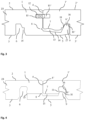
Figure 6 shows a top view of a multitude of panels known from the prior art. Panels with such locking elements are not well suited for e.g. herringbone laying patterns. Panels that have a tongue shaped element on one of the long and one of the short sides and a groove shaped element on the other long and short sides. -
Figure 1 shows a side view of a cut off panel (1), focusing on the locking system according to the present invention. A horizontal locking element (9) is mounted on a protruding lip (5). The horizontal locking element is designed in such a way, that it fits into a horizontal locking groove (6) of a neighboring panel (1') and thereby provides locking in a horizontal direction. The panel (1) has an upper side (2), which may or may not be decorated or covered by an additional abrasion resistant surface. Furthermore, the panel (1) may or may not have a decorative bevel (20) at its edge. With the embodiment shown inFigure 1 , a start notch (8) is created in the panel (1). By applying a downward force at the end of the protruding lip (5), for example by applying a downward pressure by hand on the abutment surface (16), a lever is created by the protruding lip (5). This lever is further lengthened by the start notch (8) which thereby acts as starting point for a crack. This crack intentionally propagates from the start notch (8) to an end notch surface (15). -
Figure 2 shows another side view of a cut off panel (1) according to the invention.Figure 2 shows how the protruding lip (5) with the horizontal locking element (9) is detached from the panel (1) along a predetermined break off surface (7, 7'). -
Figure 3 shows a side view of two panels (1, 1') which are now joined together. Here the horizontal locking element (9) on the protruding lip (5) of a first panel (1) is fitted into the horizontal locking groove (6') of a second panel (1') and thereby prevents any movement in the horizontal direction. The protruding lip (5) of the second panel (1') has been removed by detachment along the predetermined break off surface (7) in order to achieve said horizontal locking. - In the embodiment of
Figure 3 , vertical locking is simultaneously achieved in several ways:
Firstly, vertical locking against a movement of both panels (1,1') towards the lower side of the panels (3,3') is prevented by the substrate onto which the panels (1,1') are mounted, which is the floor, the wall, the ceiling or any further coverings thereof. - Secondly, vertical locking against a movement of the second panel (1') towards the lower side if the panel (3') is prevented by the abutment surfaces (16,16').
- Thirdly, an insertable locking element (12) is provided which is inserted into the vertical locking grooves (10,10') of both panels (1,1'). This insertable locking element (12) together with the locking grooves (10,10') prevent vertical movement of both panels in both vertical directions, towards the lower sides (3,3') and the upper sides (2,2'). The insertable locking element may either be inserted into the right groove by the person installing the panels, or by being pre-mounted in the factory. In the case that the insertable locking elements (12) are pre-mounted at the production facility, a user friendly solution is obtained by mounting the insertable locking elements (12) into the vertical locking grooves (10,10') on all four sides of rectangular panels, such that the person installing the panels can remove them together with the detachable protruding lips (5) as required for the particular laying pattern.
- It is clear that with the many different types of possible materials or material combinations out of which the panels (1) according to the invention can be made, it cannot be expected that the predetermined break-off surface (7) is always a smooth and straight, perfect surface. For panel materials such as e.g. wood based fiber boards known as MDF/HDF laminate, a generally irregular break-off surface (7) is rather to be expected. The geometry of the break off surface (7) can only be predetermined within limits. This is why it is important to choose the start notch (8) at some vertical distance above the upper lip surface (14). By this measure, a crack gap (13) is achieved, which can accommodate any irregular break off surface (7). This is important in that only the abutment surfaces (16,16') are intended to touch in the horizontal plane and not the upper lip surface (14) somewhere at the irregular break off surface (7), as this would result in panels which have their respective upper sides (2,2') in different planes thereby resulting in an irregular paneled surface. It is also important to add a well defined end notch surface (15) into which the crack will exit because it enables the crack to travel the shortest available distance. In the embodiments of
figures 1 to 3 and5 , a slightly inclined contact surface (18) is chosen, which enables horizontal locking. The inclination of the locking surface (18) enables to pull two panels (1,1') towards each other in the final laying stage and is chosen to be 40 to 80 degrees to laying plane. A further inclined surface on the horizontal locking element (9) between the locking surface (18) and the abutment surface (16) additionally also serves as a guiding surface (19) to help to align the panels during laying. - For those panel materials or combinations of materials which exhibit some elasticity, the thickness of the protruding lip (5) is carefully chosen and a further inclined bend surface (17) is added below the horizontal locking element (9) so that when a second panel (1') is joined by generally pushing it downward, the protruding lip (5) can be elastically deformed to some degree, thereby providing a slight snapping action which further holds the panels together.
-
Figure 4 shows a side view of two cut off panels (1, 1') joined by an alternative embodiment of the locking system according to the invention. In this embodiment, vertical locking is achieved by a vertical locking element (11) which interacts with a vertical locking groove (10) on the horizontal locking element (9). For some panel materials or material pairings it can be a mechanical or an economical advantage to provide the protruding lip (5), together with the horizontal locking element 9) by gluing the protruding lip (5) to a panel (1) at the factory, so that the glued surface then acts as predetermined break off surface. Such a solution can be chosen e.g. for ceramic panels or tiles with a protruding lip (5) made of a plastic material. -
Figure 5 shows a side view of a panel (1) with another alternative embodiment of the locking system according to the invention. In this embodiment, no mechanical means are provided for locking in the vertical direction away from the laying plane. However, since the protruding lip (5) together with the front end of the panel (4) and the horizontal locking element (9) form a trough, an adhesive or a glue may be provided onto the upper lip surface to provide the locking function in the vertical direction away from the laying plane. - In the panel with a detachable protruding lip according to the present invention a very good balance between the properties "easy removable" before the laying process and ensuring a "stable connection" after the laying process has been realized. There is only a small risk that the panel is damaged when removing the protruding lip, because the protruding lip can be removed after laying, so that forces acting on the panel are not critical. Furthermore, the protruding lip is easily removable manually without using any tools.
-
- 1, 1':
- Panel
- 2, 2':
- Upper side of the panel
- 3, 3':
- Lower side of the panel
- 4, 4':
- Front end of the panel
- 5:
- Protruding lip
- 6:
- Horizontal locking groove
- 7, 7':
- Predetermined break-off surface
- 8:
- Start notch
- 9:
- Horizontal locking element
- 10:
- Vertical locking groove
- 11:
- Vertical locking element
- 12:
- Insertable locking element
- 13:
- Crack gap
- 14:
- Upper lip surface
- 15:
- End notch
- 16, 16':
- Abutment surface
- 17:
- Bend surface
- 18:
- Locking surface
- 19:
- Guiding surface
- 20, 20':
- Decorative bevel
- 21:
- Missing locking elements
- 22:
- Superfluous locking elements
- 23:
- Core of the panel
Claims (15)
- Panel (1) for wall-, ceiling- or floor coverings, comprising an upper side (2), a lower side (3), and front ends (4), defining a circumference of the panel in the installed state, andat least one front end (4) is protruded with respect to the circumference by a detachable protruding lip (5) formed at the lower side (3), one horizontal locking groove (6) being provided at the lower side (3), characterized in that,at least two detachable protruding lips (5) are fixed at the panel (1) at opposite sides of the panel (1),the protruding lips (5) having a predetermined break-off surface (7), andthe protruding lips (5) comprising at least one horizontal locking element (9), being suitable for engaging in the horizontal locking groove (6) of a neighbored panel (1'), when the protruding lip (5) of said neighbored panel (1') has been removed.
- Panel (1) according to claim 1, characterized in that the predetermined break-off surface (7) is formed by one or more start notches (8), one or more cuttings, preferably laser cuttings, one or more drillings, one or more milled slots, a density gradient within the panel (1), by means of introducing a film, adhesives, binders and/or primers and/or by using different materials in the area of the predetermined break-off surface (7).
- Panel (1) according to one of the preceding claims, characterized in that the horizontal locking element (9) retains the neighbored panel (1') in vertical and/or horizontal direction.
- Panel (1) according to one of the preceding claims, characterized in thatall front ends (4) are protruded with respect to the circumference by a detachable protruding lip (5) formed at the lower side (3) and/ora vertical locking groove (10) is incorporated in the front end (4).
- Panel (1) according to one of the preceding claims, characterized in that the panel (1) comprises, preferably consists of, a material selected from the group consisting of MDF, HDF, cork, OSB, solid wood, plywood, plastics, preferably PVC, cement fibers, basalt, rock wool, ceramics, genuine stone, metal, preferably aluminum or steel panel, glass, plastics, chipboard, laminate floorboards, and mixtures or pairings thereof.
- Panel (1) according to one of the preceding claims, characterized in that the front end (4) comprises in proximity to the upper side (2) a vertical locking groove (10) over the whole length of the front end (4) or at least over parts of the length of the front end (4).
- Panel (1) according to one of claims 3 to 4, characterized in that a vertical locking groove (10) is formed at the horizontal locking element (9), preferably said vertical looking groove (10) can accommodate vertical locking means.
- Panel (1) according to one of the preceding claims, characterized in that the panel (1) has a rectangular shape, preferably the length of the panel is an integer multiple of the width, more preferably the ratio between length and width is 1:1, 1:2, 1:3, 1:4, 1:5, 1:6, 1:7, 1:8, 1:9, 1:10, 1:11 or 1:12, most preferably the ratio between length and width is 1:6.
- Panel (1) according to one of the preceding claims, characterized in that the protruding lip (5) comprises a trough, preferably said through comprises a double-sided adhesive tape.
- Panel (1) according to one of the preceding claims, characterized in that the predetermined break-off surface (7) is formed by one start notch (8) and one end notch (15), wherein the one end notch (15) is preferably arranged in the horizontal locking groove (6) and/orthe protruding lip (5) comprises, preferably consists of a material selected from the group consisting of MDF, HDF or plastics and the core (23) comprises, preferably consists of a material selected from the group consisting of MDF, HDF or plastics, preferably PVC, more preferably the protruding lip (5) consists of plastic and the core (23) consists of MDF or HDF or PVC or mixtures thereof and/orthe protruding lip (5) comprises an inclined bend surface (17) added below the horizontal locking element (9) so that when a second panel (1') is joined by generally pushing it downward, the protruding lip (5) can be elastically deformed to some degree, thereby providing a slight snapping action which further holds the panels together and/orthe start notch (8) is oriented in a vertical distance in the range from 0,1 to 10mm above the upper lip surface (14) for forming a crack gap (13).
- Panel (1) according to one of the preceding claims, characterized in thata decorative layer and/or an abrasion resistant layer is arranged on the upper side (2), and/ora layer for insulating footstep sounds and/or a counterdraw layer is oriented below the lower side (3).
- Method for manufacturing wall-, ceiling- and/or floor coverings comprising or consisting of a plurality of panels (1) according to one of the preceding claims, wherein a first panel (1) at its front end (4) is connected with the corresponding front end (4') of the neighbored panel (1') by removing the protruding lip (5') at the predetermined break-off surface (7) and by joining the protruding lip (5) of the first panel (1) with the neighbored panel (1').
- Method according to the preceding claim, characterized in that the protruding lip (5) of the first panel (1) comprises at least one horizontal locking element (9) being suitable for engagement in the horizontal locking groove (6) of the neighbored panel (1'), whose protruding lip has been removed, wherein during joining the horizontal locking element (9) is incorporated in the horizontal locking groove (6').
- Method according to one of the two preceding claims, characterized in that
the first panel (1) and the neighbored panel (1') each have a vertical locking groove (10,10') at their front end (4,4') and prior to joining an insertable locking element (12) connecting the vertical locking grooves (10,10') is introduced in the vertical locking grooves (10,10') and/or adhesive means are provided for locking in the vertical direction. - Method for manufacturing wall-, ceiling- and/or floor coverings comprising or consisting of a plurality of panels (1) according to one of claims 1 or 3, wherein an adhesive or a glue is provided onto at least a part of the surface of the protruding lip (5) for providing a locking function in the vertical direction or the adhesive or a glue is provided onto at least a part of the front end (4).
Priority Applications (4)
| Application Number | Priority Date | Filing Date | Title |
|---|---|---|---|
| HUE17742224A HUE071513T2 (en) | 2017-07-18 | 2017-07-18 | Panels with a detachable protruding lip for wall- ceiling- or floor coverings |
| PL17742224.3T PL3655598T3 (en) | 2017-07-18 | 2017-07-18 | Panels with a detachable protruding lip for wall- ceiling- or floor coverings |
| HRP20250625TT HRP20250625T1 (en) | 2017-07-18 | 2017-07-18 | Panels with a detachable protruding lip for wall- ceiling- or floor coverings |
| RS20250495A RS66815B1 (en) | 2017-07-18 | 2017-07-18 | Panels with a detachable protruding lip for wall- ceiling- or floor coverings |
Applications Claiming Priority (1)
| Application Number | Priority Date | Filing Date | Title |
|---|---|---|---|
| PCT/EP2017/068140 WO2019015746A1 (en) | 2017-07-18 | 2017-07-18 | Panels with a detachable protruding lip for wall- ceiling- or floor coverings |
Publications (3)
| Publication Number | Publication Date |
|---|---|
| EP3655598A1 EP3655598A1 (en) | 2020-05-27 |
| EP3655598C0 EP3655598C0 (en) | 2025-04-23 |
| EP3655598B1 true EP3655598B1 (en) | 2025-04-23 |
Family
ID=59381278
Family Applications (1)
| Application Number | Title | Priority Date | Filing Date |
|---|---|---|---|
| EP17742224.3A Active EP3655598B1 (en) | 2017-07-18 | 2017-07-18 | Panels with a detachable protruding lip for wall- ceiling- or floor coverings |
Country Status (12)
| Country | Link |
|---|---|
| US (1) | US11459774B2 (en) |
| EP (1) | EP3655598B1 (en) |
| CN (1) | CN110998041B (en) |
| CA (1) | CA3069478C (en) |
| ES (1) | ES3027196T3 (en) |
| HR (1) | HRP20250625T1 (en) |
| HU (1) | HUE071513T2 (en) |
| PL (1) | PL3655598T3 (en) |
| RS (1) | RS66815B1 (en) |
| RU (1) | RU2731495C1 (en) |
| UA (1) | UA125235C2 (en) |
| WO (1) | WO2019015746A1 (en) |
Families Citing this family (7)
| Publication number | Priority date | Publication date | Assignee | Title |
|---|---|---|---|---|
| WO2021011983A1 (en) * | 2019-07-24 | 2021-01-28 | S.D. Sullivan Holdings Pty Ltd | Mosaic element and method |
| WO2021059177A1 (en) * | 2019-09-25 | 2021-04-01 | Välinge Innovation AB | A set of panels comprising a flexing groove |
| EP4034733B1 (en) * | 2019-09-25 | 2026-02-25 | Välinge Innovation AB | A set of panels comprising a flexing groove |
| CN114616377B (en) * | 2019-11-07 | 2024-07-05 | 利格朗木业技术公司 | Panel for wall covering, ceiling covering or floor covering having a removable protruding lip |
| DE202019005364U1 (en) | 2019-11-07 | 2020-05-13 | Xylo Technologies Ag | Panels with a detachable protruding lip for wall, ceiling and floor coverings |
| PL437615A1 (en) * | 2021-04-19 | 2022-10-24 | BARLINEK Spółka Akcyjna | Joint of floor panels |
| US12546121B1 (en) * | 2024-11-07 | 2026-02-10 | Clyx Bv | Wall panel or floor panel having locking means which are suitable for multiple profiles |
Family Cites Families (45)
| Publication number | Priority date | Publication date | Assignee | Title |
|---|---|---|---|---|
| US3538660A (en) * | 1967-11-27 | 1970-11-10 | Karl Moor | Prefabricated wall assembly for partitions and the like |
| SE501014C2 (en) * | 1993-05-10 | 1994-10-17 | Tony Pervan | Grout for thin liquid hard floors |
| US7131242B2 (en) * | 1995-03-07 | 2006-11-07 | Pergo (Europe) Ab | Flooring panel or wall panel and use thereof |
| US6421970B1 (en) * | 1995-03-07 | 2002-07-23 | Perstorp Flooring Ab | Flooring panel or wall panel and use thereof |
| SE9500810D0 (en) * | 1995-03-07 | 1995-03-07 | Perstorp Flooring Ab | Floor tile |
| BR7502683U (en) * | 1995-11-24 | 1996-04-09 | Jacob Abrahams | Constructive arrangements in joints of strips for laminate floors or ceilings |
| GB9624901D0 (en) * | 1995-12-05 | 1997-01-15 | Sico Inc | Portable floor |
| BE1010487A6 (en) | 1996-06-11 | 1998-10-06 | Unilin Beheer Bv | FLOOR COATING CONSISTING OF HARD FLOOR PANELS AND METHOD FOR MANUFACTURING SUCH FLOOR PANELS. |
| SE512313E (en) * | 1998-06-03 | 2004-03-16 | Valinge Aluminium Ab | Locking system and floorboard |
| IL129834A (en) * | 1999-05-06 | 2001-09-13 | Ackerstein Ind Ltd | Ground surface cover system with flexible interlocking joint for erosion control |
| SE522860C2 (en) | 2000-03-10 | 2004-03-09 | Pergo Europ Ab | Vertically joined floor elements comprising a combination of different floor elements |
| DE20008708U1 (en) * | 2000-05-16 | 2000-09-14 | Kronospan Technical Co. Ltd., Nikosia | Panels with coupling agents |
| DE20112474U1 (en) | 2001-07-28 | 2002-12-19 | M. Kaindl, Wals | Panel, for example for floor, wall and / or ceiling cladding |
| SE525558C2 (en) | 2001-09-20 | 2005-03-08 | Vaelinge Innovation Ab | System for forming a floor covering, set of floorboards and method for manufacturing two different types of floorboards |
| ATE467015T1 (en) * | 2002-04-03 | 2010-05-15 | Vaelinge Innovation Ab | FLOOR PANEL WITH INTEGRATED CONNECTING MEANS AND METHOD FOR THE PRODUCTION THEREOF |
| SE525657C2 (en) * | 2002-04-08 | 2005-03-29 | Vaelinge Innovation Ab | Flooring boards for floating floors made of at least two different layers of material and semi-finished products for the manufacture of floorboards |
| US8850769B2 (en) * | 2002-04-15 | 2014-10-07 | Valinge Innovation Ab | Floorboards for floating floors |
| EP1583875A1 (en) | 2003-01-08 | 2005-10-12 | Flooring Industries Ltd. | Floor panel, its laying and manufacturing methods |
| DE102004028757B4 (en) | 2004-04-02 | 2007-11-15 | hülsta-werke Hüls GmbH & Co. KG. | Panel element for floor, wall and / or ceiling installation and method for laying a covering, in particular a floor, wall and / or ceiling covering |
| SE527570C2 (en) | 2004-10-05 | 2006-04-11 | Vaelinge Innovation Ab | Device and method for surface treatment of sheet-shaped material and floor board |
| EP1650375B2 (en) * | 2004-10-22 | 2010-12-22 | Välinge Innovation AB | A set of floor panels |
| DE102006011887A1 (en) * | 2006-01-13 | 2007-07-19 | Akzenta Paneele + Profile Gmbh | Blocking element, panel with separate blocking element, method of installing a panel covering of panels with blocking elements, and method and device for pre-assembling a blocking element on a panel |
| SE529506C2 (en) * | 2006-02-03 | 2007-08-28 | Pergo Europ Ab | A joint cover for panels |
| SE530048C2 (en) | 2006-06-09 | 2008-02-19 | Burseryd Innovation Ab | Fasteners and method of joining dynamic bodies by means of the fastener |
| DE102006037614B3 (en) | 2006-08-10 | 2007-12-20 | Guido Schulte | Floor covering, has head spring pre-assembled in slot and protruding over end of slot, and wedge surface formed at slot or head spring such that head spring runs into wedge surface by shifting projecting end of head spring into slot |
| DE102006057491A1 (en) * | 2006-12-06 | 2008-06-12 | Akzenta Paneele + Profile Gmbh | Panel and flooring |
| US7726088B2 (en) * | 2007-07-20 | 2010-06-01 | Moritz Andre Muehlebach | Flooring system |
| DE102007042250B4 (en) * | 2007-09-06 | 2010-04-22 | Flooring Technologies Ltd. | Device for connecting and locking two building panels, in particular floor panels |
| US8029880B2 (en) * | 2008-04-24 | 2011-10-04 | Liu David C | Water resistant wide flooring boards |
| US8037656B2 (en) | 2008-08-08 | 2011-10-18 | Liu David C | Flooring boards with press down locking mechanism |
| BE1018627A5 (en) * | 2009-01-16 | 2011-05-03 | Flooring Ind Ltd Sarl | FLOOR PANEL. |
| BE1018728A3 (en) * | 2009-04-22 | 2011-07-05 | Flooring Ind Ltd Sarl | FLOOR PANEL. |
| NL2003019C2 (en) * | 2009-06-12 | 2010-12-15 | 4Sight Innovation Bv | FLOOR PANEL AND FLOOR COVERAGE CONSISING OF MULTIPLE OF SUCH FLOOR PANELS. |
| US8544230B2 (en) * | 2010-01-12 | 2013-10-01 | Valinge Innovation Ab | Mechanical locking system for floor panels |
| CN104775594B (en) * | 2010-05-10 | 2017-09-22 | 佩尔戈(欧洲)股份公司 | Floor panel assembly |
| DE102010063976B4 (en) * | 2010-12-22 | 2013-01-17 | Akzenta Paneele + Profile Gmbh | paneling |
| DE102011086846A1 (en) * | 2011-01-28 | 2012-08-02 | Akzenta Paneele + Profile Gmbh | paneling |
| JP6254519B2 (en) | 2011-03-18 | 2017-12-27 | イノテック インターナショナル プロプライエタリー リミテッド | Vertical joining system and related surface coating system |
| BR112014002872B1 (en) | 2011-08-15 | 2020-07-28 | Ceraloc Innovation Ab | construction panels provided with a locking system |
| BR112014003962B1 (en) * | 2011-08-29 | 2021-04-13 | Ceraloc Innovation Ab | FLOOR PANELS PROVIDED WITH A LOCKING SYSTEM |
| BE1022209B1 (en) * | 2012-01-12 | 2016-03-01 | I.V.C. N.V. | FLOOR PANEL |
| EP2895667B1 (en) * | 2012-08-27 | 2019-12-04 | Pergo (Europe) AB | Panel |
| US9260870B2 (en) * | 2014-03-24 | 2016-02-16 | Ivc N.V. | Set of mutually lockable panels |
| CA2940112C (en) | 2014-03-24 | 2023-01-03 | Ivc N.V. | A set of mutually lockable panels |
| KR102398945B1 (en) * | 2014-04-10 | 2022-05-16 | 베리알록 엔브이 | Floor board with universal connection system |
-
2017
- 2017-07-18 HR HRP20250625TT patent/HRP20250625T1/en unknown
- 2017-07-18 RU RU2020102049A patent/RU2731495C1/en active
- 2017-07-18 HU HUE17742224A patent/HUE071513T2/en unknown
- 2017-07-18 CN CN201780093317.6A patent/CN110998041B/en active Active
- 2017-07-18 ES ES17742224T patent/ES3027196T3/en active Active
- 2017-07-18 EP EP17742224.3A patent/EP3655598B1/en active Active
- 2017-07-18 PL PL17742224.3T patent/PL3655598T3/en unknown
- 2017-07-18 RS RS20250495A patent/RS66815B1/en unknown
- 2017-07-18 WO PCT/EP2017/068140 patent/WO2019015746A1/en not_active Ceased
- 2017-07-18 CA CA3069478A patent/CA3069478C/en active Active
- 2017-07-18 US US16/632,151 patent/US11459774B2/en active Active
- 2017-07-18 UA UAA202000327A patent/UA125235C2/en unknown
Also Published As
| Publication number | Publication date |
|---|---|
| CA3069478A1 (en) | 2019-01-24 |
| US20200232225A1 (en) | 2020-07-23 |
| EP3655598A1 (en) | 2020-05-27 |
| PL3655598T3 (en) | 2025-07-14 |
| RS66815B1 (en) | 2025-06-30 |
| US11459774B2 (en) | 2022-10-04 |
| ES3027196T3 (en) | 2025-06-13 |
| CN110998041A (en) | 2020-04-10 |
| EP3655598C0 (en) | 2025-04-23 |
| RU2731495C1 (en) | 2020-09-03 |
| CN110998041B (en) | 2022-08-16 |
| HUE071513T2 (en) | 2025-09-28 |
| CA3069478C (en) | 2023-08-01 |
| UA125235C2 (en) | 2022-02-02 |
| HRP20250625T1 (en) | 2025-07-18 |
| WO2019015746A1 (en) | 2019-01-24 |
Similar Documents
| Publication | Publication Date | Title |
|---|---|---|
| US11428014B2 (en) | Mechanical locking system for floor panels | |
| US11459774B2 (en) | Panels with a detachable protruding lip for wall- , ceiling- or floor coverings | |
| US10697187B2 (en) | Mechanical locking system for floor panels | |
| EP4055236B1 (en) | Panels with a detachable protruding lip for wall-, ceiling- or floor coverings | |
| US10975577B2 (en) | Mechanical locking of floor panels with a flexible tongue | |
| US9725912B2 (en) | Mechanical locking system for floor panels | |
| CN101238261B (en) | A mechanical locking system for floor panels provided with sliding lock, an installation method and a production method therefore | |
| CN103649437B (en) | Mechanical locking system for floor panels | |
| PL210099B1 (en) | Flooring and method for laying and manufacturing the same | |
| EA043364B1 (en) | PANELS WITH A REMOVABLE PROJECTING EDGE FOR WALL, CEILING OR FLOOR COVERINGS |
Legal Events
| Date | Code | Title | Description |
|---|---|---|---|
| REG | Reference to a national code |
Ref country code: HR Ref legal event code: TUEP Ref document number: P20250625T Country of ref document: HR |
|
| STAA | Information on the status of an ep patent application or granted ep patent |
Free format text: STATUS: UNKNOWN |
|
| STAA | Information on the status of an ep patent application or granted ep patent |
Free format text: STATUS: THE INTERNATIONAL PUBLICATION HAS BEEN MADE |
|
| PUAI | Public reference made under article 153(3) epc to a published international application that has entered the european phase |
Free format text: ORIGINAL CODE: 0009012 |
|
| STAA | Information on the status of an ep patent application or granted ep patent |
Free format text: STATUS: REQUEST FOR EXAMINATION WAS MADE |
|
| 17P | Request for examination filed |
Effective date: 20200210 |
|
| AK | Designated contracting states |
Kind code of ref document: A1 Designated state(s): AL AT BE BG CH CY CZ DE DK EE ES FI FR GB GR HR HU IE IS IT LI LT LU LV MC MK MT NL NO PL PT RO RS SE SI SK SM TR |
|
| AX | Request for extension of the european patent |
Extension state: BA ME |
|
| DAV | Request for validation of the european patent (deleted) | ||
| DAX | Request for extension of the european patent (deleted) | ||
| STAA | Information on the status of an ep patent application or granted ep patent |
Free format text: STATUS: EXAMINATION IS IN PROGRESS |
|
| 17Q | First examination report despatched |
Effective date: 20230203 |
|
| RAP3 | Party data changed (applicant data changed or rights of an application transferred) |
Owner name: LIGNUM TECHNOLOGIES AG |
|
| GRAP | Despatch of communication of intention to grant a patent |
Free format text: ORIGINAL CODE: EPIDOSNIGR1 |
|
| STAA | Information on the status of an ep patent application or granted ep patent |
Free format text: STATUS: GRANT OF PATENT IS INTENDED |
|
| INTG | Intention to grant announced |
Effective date: 20241120 |
|
| GRAS | Grant fee paid |
Free format text: ORIGINAL CODE: EPIDOSNIGR3 |
|
| GRAA | (expected) grant |
Free format text: ORIGINAL CODE: 0009210 |
|
| STAA | Information on the status of an ep patent application or granted ep patent |
Free format text: STATUS: THE PATENT HAS BEEN GRANTED |
|
| AK | Designated contracting states |
Kind code of ref document: B1 Designated state(s): AL AT BE BG CH CY CZ DE DK EE ES FI FR GB GR HR HU IE IS IT LI LT LU LV MC MK MT NL NO PL PT RO RS SE SI SK SM TR |
|
| REG | Reference to a national code |
Ref country code: GB Ref legal event code: FG4D |
|
| REG | Reference to a national code |
Ref country code: CH Ref legal event code: EP |
|
| REG | Reference to a national code |
Ref country code: DE Ref legal event code: R096 Ref document number: 602017089044 Country of ref document: DE |
|
| REG | Reference to a national code |
Ref country code: IE Ref legal event code: FG4D |
|
| REG | Reference to a national code |
Ref country code: ES Ref legal event code: FG2A Ref document number: 3027196 Country of ref document: ES Kind code of ref document: T3 Effective date: 20250613 |
|
| U01 | Request for unitary effect filed |
Effective date: 20250513 |
|
| U07 | Unitary effect registered |
Designated state(s): AT BE BG DE DK EE FI FR IT LT LU LV MT NL PT RO SE SI Effective date: 20250602 |
|
| PGFP | Annual fee paid to national office [announced via postgrant information from national office to epo] |
Ref country code: PL Payment date: 20250624 Year of fee payment: 9 |
|
| U20 | Renewal fee for the european patent with unitary effect paid |
Year of fee payment: 9 Effective date: 20250602 |
|
| PGFP | Annual fee paid to national office [announced via postgrant information from national office to epo] |
Ref country code: RS Payment date: 20250627 Year of fee payment: 9 |
|
| REG | Reference to a national code |
Ref country code: HR Ref legal event code: T1PR Ref document number: P20250625 Country of ref document: HR |
|
| PGFP | Annual fee paid to national office [announced via postgrant information from national office to epo] |
Ref country code: SK Payment date: 20250630 Year of fee payment: 9 |
|
| REG | Reference to a national code |
Ref country code: SK Ref legal event code: T3 Ref document number: E 46527 Country of ref document: SK |
|
| REG | Reference to a national code |
Ref country code: HR Ref legal event code: ODRP Ref document number: P20250625 Country of ref document: HR Payment date: 20250627 Year of fee payment: 9 |
|
| PGFP | Annual fee paid to national office [announced via postgrant information from national office to epo] |
Ref country code: HU Payment date: 20250709 Year of fee payment: 9 |
|
| REG | Reference to a national code |
Ref country code: HU Ref legal event code: AG4A Ref document number: E071513 Country of ref document: HU |
|
| PGFP | Annual fee paid to national office [announced via postgrant information from national office to epo] |
Ref country code: ES Payment date: 20250821 Year of fee payment: 9 |
|
| PG25 | Lapsed in a contracting state [announced via postgrant information from national office to epo] |
Ref country code: GR Free format text: LAPSE BECAUSE OF FAILURE TO SUBMIT A TRANSLATION OF THE DESCRIPTION OR TO PAY THE FEE WITHIN THE PRESCRIBED TIME-LIMIT Effective date: 20250724 |
|
| PGFP | Annual fee paid to national office [announced via postgrant information from national office to epo] |
Ref country code: NO Payment date: 20250718 Year of fee payment: 9 |
|
| PGFP | Annual fee paid to national office [announced via postgrant information from national office to epo] |
Ref country code: TR Payment date: 20250701 Year of fee payment: 9 |
|
| PGFP | Annual fee paid to national office [announced via postgrant information from national office to epo] |
Ref country code: GB Payment date: 20250722 Year of fee payment: 9 |
|
| PGFP | Annual fee paid to national office [announced via postgrant information from national office to epo] |
Ref country code: HR Payment date: 20250702 Year of fee payment: 9 |
|
| PGFP | Annual fee paid to national office [announced via postgrant information from national office to epo] |
Ref country code: CZ Payment date: 20250701 Year of fee payment: 9 |
|
| PG25 | Lapsed in a contracting state [announced via postgrant information from national office to epo] |
Ref country code: IS Free format text: LAPSE BECAUSE OF FAILURE TO SUBMIT A TRANSLATION OF THE DESCRIPTION OR TO PAY THE FEE WITHIN THE PRESCRIBED TIME-LIMIT Effective date: 20250823 |
|
| PG25 | Lapsed in a contracting state [announced via postgrant information from national office to epo] |
Ref country code: SM Free format text: LAPSE BECAUSE OF FAILURE TO SUBMIT A TRANSLATION OF THE DESCRIPTION OR TO PAY THE FEE WITHIN THE PRESCRIBED TIME-LIMIT Effective date: 20250423 |
|
| REG | Reference to a national code |
Ref country code: CH Ref legal event code: H13 Free format text: ST27 STATUS EVENT CODE: U-0-0-H10-H13 (AS PROVIDED BY THE NATIONAL OFFICE) Effective date: 20260224 |
|
| PLBE | No opposition filed within time limit |
Free format text: ORIGINAL CODE: 0009261 |
|
| STAA | Information on the status of an ep patent application or granted ep patent |
Free format text: STATUS: NO OPPOSITION FILED WITHIN TIME LIMIT |
|
| REG | Reference to a national code |
Ref country code: CH Ref legal event code: L10 Free format text: ST27 STATUS EVENT CODE: U-0-0-L10-L00 (AS PROVIDED BY THE NATIONAL OFFICE) Effective date: 20260304 |
|
| 26N | No opposition filed |
Effective date: 20260126 |
|
| PG25 | Lapsed in a contracting state [announced via postgrant information from national office to epo] |
Ref country code: CH Free format text: LAPSE BECAUSE OF NON-PAYMENT OF DUE FEES Effective date: 20250731 |
|
| PG25 | Lapsed in a contracting state [announced via postgrant information from national office to epo] |
Ref country code: IE Free format text: LAPSE BECAUSE OF NON-PAYMENT OF DUE FEES Effective date: 20250718 |
|
| PG25 | Lapsed in a contracting state [announced via postgrant information from national office to epo] |
Ref country code: MC Free format text: LAPSE BECAUSE OF FAILURE TO SUBMIT A TRANSLATION OF THE DESCRIPTION OR TO PAY THE FEE WITHIN THE PRESCRIBED TIME-LIMIT Effective date: 20250423 |
|
| PG25 | Lapsed in a contracting state [announced via postgrant information from national office to epo] |
Ref country code: CY Free format text: LAPSE BECAUSE OF FAILURE TO SUBMIT A TRANSLATION OF THE DESCRIPTION OR TO PAY THE FEE WITHIN THE PRESCRIBED TIME-LIMIT Effective date: 20250423 |
|
| U20 | Renewal fee for the european patent with unitary effect paid |
Year of fee payment: 10 Effective date: 20260709 |