EP3655045B1 - Method of sterilizing and introducing fluid into a product bag - Google Patents
Method of sterilizing and introducing fluid into a product bag Download PDFInfo
- Publication number
- EP3655045B1 EP3655045B1 EP18746548.9A EP18746548A EP3655045B1 EP 3655045 B1 EP3655045 B1 EP 3655045B1 EP 18746548 A EP18746548 A EP 18746548A EP 3655045 B1 EP3655045 B1 EP 3655045B1
- Authority
- EP
- European Patent Office
- Prior art keywords
- filtration device
- filter membrane
- fluid
- chamber
- filter
- Prior art date
- Legal status (The legal status is an assumption and is not a legal conclusion. Google has not performed a legal analysis and makes no representation as to the accuracy of the status listed.)
- Active
Links
Images


Classifications
-
- A—HUMAN NECESSITIES
- A61—MEDICAL OR VETERINARY SCIENCE; HYGIENE
- A61L—METHODS OR APPARATUS FOR STERILISING MATERIALS OR OBJECTS IN GENERAL; DISINFECTION, STERILISATION OR DEODORISATION OF AIR; CHEMICAL ASPECTS OF BANDAGES, DRESSINGS, ABSORBENT PADS OR SURGICAL ARTICLES; MATERIALS FOR BANDAGES, DRESSINGS, ABSORBENT PADS OR SURGICAL ARTICLES
- A61L2/00—Disinfection or sterilisation of materials or objects, in general; Accessories therefor
- A61L2/26—Accessories
-
- B—PERFORMING OPERATIONS; TRANSPORTING
- B65—CONVEYING; PACKING; STORING; HANDLING THIN OR FILAMENTARY MATERIAL
- B65B—MACHINES, APPARATUS OR DEVICES FOR, OR METHODS OF, PACKAGING ARTICLES OR MATERIALS; UNPACKING
- B65B3/00—Packaging plastic material, semiliquids, liquids or mixed solids and liquids, in individual containers or receptacles, e.g. bags, sacks, boxes, cartons, cans, or jars
- B65B3/003—Filling medical containers such as ampoules, vials, syringes or the like
-
- A—HUMAN NECESSITIES
- A61—MEDICAL OR VETERINARY SCIENCE; HYGIENE
- A61J—CONTAINERS SPECIALLY ADAPTED FOR MEDICAL OR PHARMACEUTICAL PURPOSES; DEVICES OR METHODS SPECIALLY ADAPTED FOR BRINGING PHARMACEUTICAL PRODUCTS INTO PARTICULAR PHYSICAL OR ADMINISTERING FORMS; DEVICES FOR ADMINISTERING FOOD OR MEDICINES ORALLY; BABY COMFORTERS; DEVICES FOR RECEIVING SPITTLE
- A61J1/00—Containers specially adapted for medical or pharmaceutical purposes
- A61J1/05—Containers specially adapted for medical or pharmaceutical purposes for collecting, storing or administering blood, plasma or medical fluids ; Infusion or perfusion containers
- A61J1/10—Bag-type containers
-
- A—HUMAN NECESSITIES
- A61—MEDICAL OR VETERINARY SCIENCE; HYGIENE
- A61J—CONTAINERS SPECIALLY ADAPTED FOR MEDICAL OR PHARMACEUTICAL PURPOSES; DEVICES OR METHODS SPECIALLY ADAPTED FOR BRINGING PHARMACEUTICAL PRODUCTS INTO PARTICULAR PHYSICAL OR ADMINISTERING FORMS; DEVICES FOR ADMINISTERING FOOD OR MEDICINES ORALLY; BABY COMFORTERS; DEVICES FOR RECEIVING SPITTLE
- A61J1/00—Containers specially adapted for medical or pharmaceutical purposes
- A61J1/14—Details; Accessories therefor
- A61J1/1443—Containers with means for dispensing liquid medicaments in a filtered or sterile way, e.g. with bacterial filters
- A61J1/1456—Containers with means for dispensing liquid medicaments in a filtered or sterile way, e.g. with bacterial filters using liquid filters
-
- A—HUMAN NECESSITIES
- A61—MEDICAL OR VETERINARY SCIENCE; HYGIENE
- A61L—METHODS OR APPARATUS FOR STERILISING MATERIALS OR OBJECTS IN GENERAL; DISINFECTION, STERILISATION OR DEODORISATION OF AIR; CHEMICAL ASPECTS OF BANDAGES, DRESSINGS, ABSORBENT PADS OR SURGICAL ARTICLES; MATERIALS FOR BANDAGES, DRESSINGS, ABSORBENT PADS OR SURGICAL ARTICLES
- A61L2/00—Disinfection or sterilisation of materials or objects, in general; Accessories therefor
- A61L2/02—Disinfection or sterilisation of materials or objects, in general; Accessories therefor using physical processes
- A61L2/022—Filtration
-
- A—HUMAN NECESSITIES
- A61—MEDICAL OR VETERINARY SCIENCE; HYGIENE
- A61L—METHODS OR APPARATUS FOR STERILISING MATERIALS OR OBJECTS IN GENERAL; DISINFECTION, STERILISATION OR DEODORISATION OF AIR; CHEMICAL ASPECTS OF BANDAGES, DRESSINGS, ABSORBENT PADS OR SURGICAL ARTICLES; MATERIALS FOR BANDAGES, DRESSINGS, ABSORBENT PADS OR SURGICAL ARTICLES
- A61L2103/00—Materials or objects being the target of disinfection or sterilisation
- A61L2103/05—Living organisms or biological materials
-
- A—HUMAN NECESSITIES
- A61—MEDICAL OR VETERINARY SCIENCE; HYGIENE
- A61L—METHODS OR APPARATUS FOR STERILISING MATERIALS OR OBJECTS IN GENERAL; DISINFECTION, STERILISATION OR DEODORISATION OF AIR; CHEMICAL ASPECTS OF BANDAGES, DRESSINGS, ABSORBENT PADS OR SURGICAL ARTICLES; MATERIALS FOR BANDAGES, DRESSINGS, ABSORBENT PADS OR SURGICAL ARTICLES
- A61L2202/00—Aspects relating to methods or apparatus for disinfecting or sterilising materials or objects
- A61L2202/10—Apparatus features
- A61L2202/12—Apparatus for isolating biocidal substances from the environment
- A61L2202/121—Sealings, e.g. doors, covers, valves, sluices
-
- A—HUMAN NECESSITIES
- A61—MEDICAL OR VETERINARY SCIENCE; HYGIENE
- A61L—METHODS OR APPARATUS FOR STERILISING MATERIALS OR OBJECTS IN GENERAL; DISINFECTION, STERILISATION OR DEODORISATION OF AIR; CHEMICAL ASPECTS OF BANDAGES, DRESSINGS, ABSORBENT PADS OR SURGICAL ARTICLES; MATERIALS FOR BANDAGES, DRESSINGS, ABSORBENT PADS OR SURGICAL ARTICLES
- A61L2202/00—Aspects relating to methods or apparatus for disinfecting or sterilising materials or objects
- A61L2202/10—Apparatus features
- A61L2202/12—Apparatus for isolating biocidal substances from the environment
- A61L2202/123—Connecting means
-
- A—HUMAN NECESSITIES
- A61—MEDICAL OR VETERINARY SCIENCE; HYGIENE
- A61L—METHODS OR APPARATUS FOR STERILISING MATERIALS OR OBJECTS IN GENERAL; DISINFECTION, STERILISATION OR DEODORISATION OF AIR; CHEMICAL ASPECTS OF BANDAGES, DRESSINGS, ABSORBENT PADS OR SURGICAL ARTICLES; MATERIALS FOR BANDAGES, DRESSINGS, ABSORBENT PADS OR SURGICAL ARTICLES
- A61L2202/00—Aspects relating to methods or apparatus for disinfecting or sterilising materials or objects
- A61L2202/10—Apparatus features
- A61L2202/18—Aseptic storing means
- A61L2202/181—Flexible packaging means, e.g. permeable membranes, paper
-
- A—HUMAN NECESSITIES
- A61—MEDICAL OR VETERINARY SCIENCE; HYGIENE
- A61M—DEVICES FOR INTRODUCING MEDIA INTO, OR ONTO, THE BODY; DEVICES FOR TRANSDUCING BODY MEDIA OR FOR TAKING MEDIA FROM THE BODY; DEVICES FOR PRODUCING OR ENDING SLEEP OR STUPOR
- A61M2207/00—Methods of manufacture, assembly or production
-
- B—PERFORMING OPERATIONS; TRANSPORTING
- B65—CONVEYING; PACKING; STORING; HANDLING THIN OR FILAMENTARY MATERIAL
- B65B—MACHINES, APPARATUS OR DEVICES FOR, OR METHODS OF, PACKAGING ARTICLES OR MATERIALS; UNPACKING
- B65B3/00—Packaging plastic material, semiliquids, liquids or mixed solids and liquids, in individual containers or receptacles, e.g. bags, sacks, boxes, cartons, cans, or jars
- B65B3/003—Filling medical containers such as ampoules, vials, syringes or the like
- B65B3/006—Related operations, e.g. scoring ampoules
Definitions
- Conventional methods for manufacturing bags of sterile solution include filling bags in a clean environment with a solution, sealing the filled bag of solution, and then sterilizing the fluid and bags in a sterilizing autoclave. This can be referred to as terminal sterilization.
- Another conventional method is to provide a sterile solution and fill and seal sterile bags in an extremely high-quality environment designed and controlled to prevent contamination of the solution during the filling process and to seal the filled bag. This can be referred to as an aseptic filling process.
- the aseptic manufacturing process must occur in a sterile working environments, and require expensive equipment, stringent procedures and extensive monitoring to ensure that solution product bags meet certain environmental and manufacturing regulatory standards. Sterilizing a working environment, by itself, can be costly and time consuming. Technicians involved in the filling process must also follow rigorous operational protocols to ensure the environment is not contaminated so as to produce safe and sterile products. Even with these safeguards, unless it can be verified that the solution entering the bag is sterile, there is a risk that contaminants may have inadvertently been introduced into the solution during filling/sealing, and once introduced, unless the solution later passes through a viable sterilizing filter, the contaminants will remain in the solution. Again due to these requirements, sterile solution product bags are often produced in centralized locations and shipped some distance to their destination for use.
- EP2684551 shows an example of a system for introducing oxygen into a product bag carrying blood by means of a sterilizing filter.
- a first aspect of the present disclosure provides a product bag having a bladder and an elongated filtration device.
- the bladder includes opposing first and second film layers defining a product chamber.
- the first and second film layers are sealed together along a perimeter seal extending along at least a portion of a perimeter of the bladder.
- the elongated filtration device includes a housing, a filtration membrane disposed in the housing, an inlet adapted for receiving a fluid to be filtered, and an outlet in fluid communication with the product chamber.
- a majority of the elongated filtration device is embedded between the first and second film layers of the perimeter seal of the bladder to provide for a compact form factor.
- the bladder is generally rectangular in shape having opposite first and second short sides and opposite first and second long sides, and wherein the filtration device is embedded in the perimeter seal along the first long side.
- the filter membrane is shaped as a hollow fiber with a wall and pores residing in the wall of the fiber.
- the product chamber comprises first and second chamber portions isolated from each other by a chamber seal.
- the filter membrane comprises a plurality of filter membranes.
- the filter membrane has a wall thickness in the range of approximately 150 ⁇ m to approximately 500 ⁇ m.
- the filter membrane is made of at least one of the following materials: a polyolefin, polyvinylidene fluoride, polymethylmethacrylate, polyacrylonitrile, polysulfone, polyethersulfone, and a polymer containing cationic charges.
- the filter membrane includes at least one U-shaped hollow fiber filter membrane secured in a U-shaped configuration by a filter membrane housing contained within a filter body.
- the filter membrane comprises a plurality of parallel hollow fiber membrane filters secured in a side-by-side configuration.
- the filter membrane comprises a plurality of parallel hollow fiber membrane filters arranged in a circular pattern.
- the product chamber is a sterile product chamber.
- the product bag further includes a medicinal or nutritional concentrate disposed in the product chamber.
- a twenty-third aspect of the present disclosure includes a method of sterilizing and introducing fluid into a product bag.
- the method includes providing a bladder comprising opposing first and second film layers defining a sterile product chamber, the first and second film layers sealed together along a perimeter seal extending along at least a portion of a perimeter of the bladder, the perimeter seal including at least one break defining a bridging channel in fluid communication with the sterile product chamber.
- the method further includes providing a filtration device having an inlet end adapted for receiving a fluid to be sterilized, and an outlet end in fluid communication with the sterile product chamber via the bridging channel, the filtration device having a filter membrane with a nominal pore size in a range of approximately 0.1 ⁇ m to approximately 0.5 ⁇ m.
- the method further includes introducing a pharmaceutical fluid into the sterile product chamber through the filtration device and bridging channel such that a sterile pharmaceutical fluid resides within the sterile product chamber.
- the method further includes sealing the opposing first and second layer films together across the bridging channel to create a bridge seal to maintain the sterilized pharmaceutical fluid in the sterile product chamber.
- the method further includes cutting the filtration device off of the product bag.
- cutting the filtration device off of the product bag comprises cutting across the bridging seal.
- the method further includes performing a filter integrity test on the filter membrane after cutting the filtration device off of the product bag.
- performing the filter integrity test comprises performing one of a pressure degradation test, a bubble point test, a water intrusion test, or a water flow test.
- sealing the opposing first and second film layers together includes heat sealing the first and second film layers together to provide a hermetic seal.
- introducing the pharmaceutical fluid into the sterile product chamber through the filtration device comprises introducing the pharmaceutical fluid through a plurality of filter membranes.
- introducing the pharmaceutical fluid into the sterile product chamber through the filtration device comprises introducing the pharmaceutical fluid through an open outlet end and a sealed outlet end of a hollow fiber of the filter membrane.
- introducing the pharmaceutical fluid into the sterile product chamber through the filtration device comprises introducing the pharmaceutical fluid through a filter membrane having a wall thickness in the range of approximately 150 ⁇ m to approximately 500 ⁇ m.
- introducing the pharmaceutical fluid into the sterile product chamber through the filtration device comprises introducing the pharmaceutical fluid through a filter membrane having a longitudinal dimension in the range of approximately 3 cm to approximately 420 cm, an inner diameter in the range of approximately 2 mm to approximately 4 mm, and an outer diameter in the range of approximately 2.3 mm to approximately 5 mm.
- introducing the pharmaceutical fluid into the sterile product chamber through the filtration device comprises introducing the pharmaceutical fluid through a filter membrane made of at least one of the following materials: a polyolefin, polyvinylidene fluoride, polymethylmethacrylate, polyacrylonitrile, polysulfone, polyethersulfone, and a polymer containing cationic charges.
- introducing the pharmaceutical fluid into the sterile product chamber through the filtration device comprises introducing the pharmaceutical fluid through a filter having at least one U-shaped hollow fiber filter membrane secured in a U-shaped configuration by a filter membrane housing contained within a filter body.
- introducing the pharmaceutical fluid through a filter having at least one U-shaped hollow fiber filter membrane comprises introducing diluent through a plurality of U-shaped hollow fiber filter membranes.
- introducing the pharmaceutical fluid into the sterile product chamber through the filtration device comprises introducing the pharmaceutical fluid through a plurality of parallel hollow fiber membrane filters secured in a side-by-side configuration.
- introducing the pharmaceutical fluid into the sterile product chamber through the filtration device comprises introducing the pharmaceutical fluid through a plurality of parallel hollow fiber membrane filters arranged in a circular pattern.
- the present disclosure is directed to a device and method related to sterilizing and introducing pharmaceutical fluids (e.g., solutions, diluents, drug products, etc.) into a sterile product bag in cost-effective manner.
- the device includes a product bag constructed of two or more films sealed at a perimeter seal and defining a chamber such as in typical medical grade solution bags. Additionally, however, the product bag includes a sterilizing filtration device such that non-sterile pharmaceutical fluids can be introduced into the product bag in non-traditional environments such as hospitals and/or pharmacies.
- the filtration device is embedded into the perimeter seal of the product bag in a manner that facilitates filling, and subsequently sealing of the bag, removal and testing of the filter. Embedding the filtration device into the perimeter seal provides a compact configuration which adapts well to conventional manufacturing, sterilizing, shipping, and storage practices.
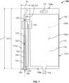
- FIGS. 1 and 2A-2C illustrate a first embodiment of a product bag 100 constructed in accordance with the principles of the present disclosure.
- the product bag 100 includes a bladder 102 and a filtration device 103 embedded into the bladder 102 to provide a compact form factor susceptible to conventional sterilization, shipping, handling, storage, and other procedures.
- one embodiment of the bladder 102 includes at least first and second opposing film layers 105a, 105b bonded together along a perimeter seal 107 and forming a product chamber 110.
- the first and/or second film layers 105a, 105b can include multi-layer film products for protecting the contents of the product bag 100 against degradation due to light exposure or other environmental concerns.
- the bladder 102 is generally rectangular in shape having opposite top and bottom short sides 109a, 109b and opposite left and right long sides 111a, 111b. Additionally, as depicted, this embodiment, the perimeter seal 107 extends only along the top side 109a, left side 111a, and bottom side 109b. This is because the depicted version of the bladder 102 is constructed from a single piece of film folded in half at a seam 113 to form the right side 111b. Thus, in this version, the first and second film layers 105a, 105b are portions of a common sheet of film. In other versions, the perimeter seal 107 can also extend along the seam 113 at the right side 111b of the bladder 102.
- the first and second film layers 105a, 105b can be separate sheets such that the perimeter seal 107 also extends along the right side 111b in order to bond the sheets together to form the chamber 110.
- the product bag 100 can include an opening 117 disposed through the perimeter seal 107 at the top side 109a and an outlet port 119 extending through the perimeter seal 107 at the bottom side 109b.
- the opening 117 can be for hanging the product bag 100, while the outlet port 119 extends through the perimeter seal 107 in fluid communication with the chamber 110 for delivering contents of the product bag to an administration set during patient administration, for example.
- the product bag 100 includes the filtration device 103 embedded in the bladder 102 for a compact product configuration. More particularly, as shown, the filtration device 103 is embedded into the perimeter seal 107 along the left side 111a of the product bag 100. That is, the perimeter seal 107 at the left side 111a of the product bag 100 includes a retention section 121 that extends from the bottom side 109b to the top side 109a of the bag 100 and has a length dimension L that is greater than a width dimension W. So configured, the retention section 121 is an elongated section of the perimeter seal 107 having a longitudinal axis A extending along the left side 111a of the product bag 100 parallel to the chamber 110.
- the retention section 121 moreover retains the filtration device 103 within a retention channel 123 defined between the first and second film layers 105a, 105b that are bonded together to form the perimeter seal 107.
- the retention channel 123 is elongated and extends from the bottom side 109b of the product bag 100 almost entirely to the top side 109a.
- the retention channel 123 extends parallel to and/or co-axial with the longitudinal axis A of the retention section 121.
- the retention channel 123 includes an inlet 125 and the opposite end of the retention channel 123 terminates at an outlet 129.
- the outlet 129 is located at a break 125 in the perimeter seal 107, which can be referred to as a bridging channel 127 that provides fluid communication between the retention channel 123 and the product chamber 110.
- the retention channel 123 is tapered from the inlet 125 to the outlet 129. That is, a substantial portion of the cross-sectional diameter of the retention channel 123 converges from the inlet 125 to the outlet 129. This converging or tapered geometry can assist with installing the filtration device 103 in the retention channel 123 as will be described.
- the filtration device 103 of the product bag 100 of the present disclosure can take many different forms suitable to sterilize fluids as they pass through the filtration device 103 and into the product chamber 110.
- the embodiment of the filtration device 103 depicted in FIG. 1 is elongated and extends parallel to and/or co-axially with the longitudinal axis A of the retention section 121 of the perimeter seal 107 such that a majority, if not all, of the filtration device 103 is embedded within the perimeter seal 107.
- the filtration device 103 can include a housing 104, a filter membrane 170 disposed in-line with the housing 104, and a sterile closure cap and connector assembly 108.
- the housing 104 is a hollow narrow tube of uniform diameter fixed in the retention channel 123 of the retention section 121 of the perimeter seal 107.
- the housing 104 includes an inlet 124 disposed in proximity to the inlet 125 of the retention channel 123, and an outlet 126 disposed in proximity to the outlet 129 of the retention channel 123.
- the sterile closure cap and connector assembly 108 can be disposed outside of the retention channel 123, as shown, or inside of the retention channel 123.
- the disclosed embodiment of the retention chamber 123 optionally includes a tapered or convergent geometry.
- the inlet 125 of the retention chamber 123 has a diameter that is greater than a diameter of the housing 104 of the filtration device 103
- the outlet 129 of the retention chamber 123 has a diameter that is substantially similar to the diameter of the housing 104 of the filtration device 103.
- an elongated annular gap 131 is present between a portion of the filtration device 103 and an interior wall of the retention chamber 123.
- the geometrical relationship between the filtration device 103 and the retention channel 123 can vary, and a hermetic seal can be provided in order to ensure and maintain a sterile environment within the product chamber 110 before, during, and after use of the product bag 100.
- a mechanical "tack seal" between container the film and the connector assembly 108 may be formed at the inlet 125 to provide mechanical stability of the container during handling, but a hermetic seal at inlet 125 may not be included or be necessary.
- the entirety of the retention chamber 123 and housing 104 of the filtration device 103 can share a common diameter and the hermetic seal can extend along the entire length of the filtration device 103.
- the inlet 124 of the filtration device 103 is located at the bottom side 109b, which is opposite the hanging opening 117, of the product bag 100.
- This orientation, relative to gravity, can be beneficial when filling the product bag 100 with solutions that tend to foam such as certain antibiotics because this bottom fill procedure can reduce aeration during filling.
- the product bag 100 described with respect to FIGS. 1 and 2A-2C is described as including a product chamber 110.
- the product chamber 110 can be completely empty and sterile prior to introducing any pharmaceutical fluid into the chamber 110 through the filtration device 130.
- the product chamber 110 can be pre-filled with a sterile product concentrate such as a medicament or nutrient concentrate in the form of a powder, a granulate, a gel, a foam, a liquid, etc.
- introducing the pharmaceutical fluid into the chamber 110 can include introducing a diluent into the chamber 110 to reconstitute the concentrate into a form that can then be administered to a patient.
- the product bag 100 in FIGS. 1 and 2A-2C is described as including a bladder 102 with a single product chamber 110, other embodiments can include multiple chamber portions.
- the retention section 121 of the perimeter seal 107 which retains the filtration device 103, is disposed on the right side 111b of the bag 100. But this is merely a product of the orientation of the bag in FIG. 4 .
- the filtration device 103 in FIG. 4 is depicted as having a shorter longitudinal dimension than in FIGS. 1-3 because the outlet 126 of the filtration device 103 must align with the outlet 129 of the retention channel 123 and bridging channel 127 to communicate with the first chamber portion 110a. All other aspects of the relationship between the filtration device 103, retention section 121, and retention channel 123 remain the same as that described above with respect to the same components in FIGS. 1-3 .
- FIG. 5 depicts one embodiment of the filtration device 103 where the housing 104 comprises a stem 156, and a hollow connector 166 is used to secure the stem 156 and the filter membrane 170 together.
- the connector 166 can be part of, or coupled to, the sterile closure cap and connector assembly 108 described above in FIGS. 1-4 .
- the filter membrane 170 includes an open inlet end 160 sealingly connected to an open outlet end 168 of the hollow connector 166.
- connection may be achieved by gluing the open inlet end 160 of the filter membrane 170 to the open outlet end 168 of the connector 166 with, for example, an epoxy resin, a polyurethane resin, a cyanoacrylate resin, a UV curing acrylic adhesive, or a solvent for the material of the hollow connector 166 such as cyclohexanone.
- the open outlet end 168 of the connector 166 comprises a hollow cylindrical member that fits inside of and is fixed to the open inlet end 160 of the filter membrane 170.
- an outer diameter of the open outlet end 168 of the connector 166 is substantially similar to or slightly smaller than an inner diameter of the open inlet end 160 of the filter membrane 170.
- the open inlet end 160 of the filter membrane 170 may be welded to the open outlet end 168 of the connector 166 by, for example, heat welding (e.g., introducing a hot conical metal tip into the open inlet end 150 of the filter membrane 170 to partially melt it), laser welding if the hollow connector 166 is made from a material that absorbs laser radiation, mirror welding, ultrasound welding, and friction welding.
- heat welding e.g., introducing a hot conical metal tip into the open inlet end 150 of the filter membrane 170 to partially melt it
- laser welding if the hollow connector 166 is made from a material that absorbs laser radiation
- mirror welding e.g., introducing a hot conical metal tip into the open inlet end 150 of the filter membrane 170 to partially melt it
- laser welding if the hollow connector 166 is made from a material that absorbs laser radiation
- mirror welding e.g., introducing a hot conical metal tip into the open inlet end 150 of the filter membrane 170 to partially melt it
- the hollow connector 166 further includes a fluid inlet 169.
- a pharmaceutical fluid can be fed via a connected fluid supply line, for example, into the fluid inlet 169 of the hollow connector 166.
- the fluid inlet 169 can include a Luer type fitting or other standard medical fitting.
- the pharmaceutical fluid can then travel through the hollow connector 166 and exit into the filter membrane 170 through the open outlet end 168 of the hollow connector 166.
- the hollow connector 166 also includes a sealing surface 172 to which the stem 156 is attached.
- the sealing surface 172 in this version is cylindrical and has a diameter larger than a diameter of the open outlet end 168, and is disposed generally concentric with the open outlet end 168.
- the outer diameter of the sealing surface 172 is generally identical to or slightly smaller than an inner diameter of the stem 156. So configured, the stem 156 receives the sealing surface 172 and extends therefrom to surround and protect the filter membrane 170 without contacting the surface 164 of the filter membrane 170.
- the stem 156 can be fixed to the sealing surface 172 with adhesive (e.g., a UV curing acrylic adhesive), epoxy, welding, bonding, etc.
- adhesive e.g., a UV curing acrylic adhesive
- the stem 156 receives the pharmaceutical solution after it passes through the pores 162 in the filter membrane 170. From there, the now filtered solution passes into the bladder.
- the stem structure of the open outlet end 768 of the connector 766 comprises a hollow cylindrical member that fits inside of and is fixed to the open inlet end 160 of the filter membrane 170.
- an outer diameter of the open outlet end 768 of the connector 766 is substantially similar to or slightly smaller than an inner diameter of the open inlet end 160 of the filter membrane 170.
- the filter membrane 170 has an outer diameter in the range of approximately 2.3 mm to approximately 5 mm, a longitudinal dimension in the range of approximately 3 cm to approximately 420 cm, and a wall thickness in the range of approximately 150 ⁇ m to approximately 500 ⁇ m.
- each of the plurality of pores 162 in the filter membrane 170 have a diameter less than or equal to approximately 0.2 microns.
- each pore has a diameter less than or equal to a value in a range of approximately 0.1 microns to approximately 0.5 microns, for instance, approximately 0.2 to approximately 0.4 microns.
- each pore has a diameter that is less than or equal to approximately 0.22 microns.
- FIG. 11 is a front view of a filter assembly 1000 for a product bag (not pictured) having a single U-shaped hollow fiber filter membrane 1002 contained within a filter body 1004.
- the filter membrane 1002 is secured to a filter membrane housing 1006 in the U-shaped configuration with an adhesive (i.e., a UV curing acrylic adhesive), an epoxy, welding, bonding, or other means.
- the filter membrane housing 1006 is connected to the filter body 1004 at an outlet portion 1008 of the filter body 1004.
- An inlet portion 1010 is sealably connected to the outlet portion 1008 of the filter body 1004 at a joint or other seam.
- the inlet portion 1010 of the filter body 1004 has an inlet 1012 by which a pharmaceutical fluid may enter the filter assembly 1000.
- an outer diameter of the open outlet ends 868 is substantially similar to or slightly smaller than an inner diameter of the open inlet ends 160 of the filters 155.
- the filters 155 may be welded to the open outlet ends 868 of the connector 866 by, for example, heat welding (e.g., introducing a hot conical metal tip into the open inlet ends 150 of the filters 155 to partially melt it), laser welding if the hollow connector 866 is made from a material that absorbs laser radiation, mirror welding, ultrasound welding, and friction welding.
- the filters 155 may be inserted into a mold, and a thermoplastic polymer may be injection-molded around it to form the hollow connector 866.
- Other designs and configurations for connecting the filters 155 to the open outlet ends 868 are intended to be within the scope of the present disclosure.
- the sealing surface 872 of the connector 866 can be received by the stem 156 such that the stem 156 extends therefrom to surround and protect the filters 155 without contacting the surfaces 164 of the filters 155.
- the stem 156 can be fixed to the sealing surface 872 with adhesive (e.g., a UV curing acrylic adhesive), epoxy, welding, bonding, etc.
- adhesive e.g., a UV curing acrylic adhesive
- the stem 156 receives the pharmaceutical solution after it passes through the pores 162 in the filter membrane 170. From there, the now filtered solution passes into the bladder in the same manner described above with respect to FIGS. 3-5 .
- the stem structure of the open outlet ends 868 of the connector 866 comprises a hollow cylindrical member that fits inside of and is fixed to the filters 955.
- a diameter of the open outlet ends 968 is substantially similar to or slightly smaller than an inner diameter of the filters 955.
- the filters 955 may be welded to the open outlet ends 968 of the connector 966 by, for example, heat welding (e.g., introducing a hot conical metal tip into the filters 955 to partially melt it), laser welding if the hollow connector 966 is made from a material that absorbs laser radiation, mirror welding, ultrasound welding, and friction welding.
Landscapes
- Health & Medical Sciences (AREA)
- General Health & Medical Sciences (AREA)
- Veterinary Medicine (AREA)
- Public Health (AREA)
- Life Sciences & Earth Sciences (AREA)
- Animal Behavior & Ethology (AREA)
- Epidemiology (AREA)
- Engineering & Computer Science (AREA)
- Mechanical Engineering (AREA)
- Pharmacology & Pharmacy (AREA)
- Separation Using Semi-Permeable Membranes (AREA)
- Medical Preparation Storing Or Oral Administration Devices (AREA)
- Filtering Materials (AREA)
- Packages (AREA)
- Control And Other Processes For Unpacking Of Materials (AREA)
Description
- This disclosure relates to a product bag and, more particularly, a product bag having an integral filter that allows microbial and particulate matter filtration during filling in non-traditional settings.
- Conventional methods for manufacturing bags of sterile solution, for example, include filling bags in a clean environment with a solution, sealing the filled bag of solution, and then sterilizing the fluid and bags in a sterilizing autoclave. This can be referred to as terminal sterilization. Another conventional method is to provide a sterile solution and fill and seal sterile bags in an extremely high-quality environment designed and controlled to prevent contamination of the solution during the filling process and to seal the filled bag. This can be referred to as an aseptic filling process.
- Terminal sterilization generally requires autoclaves to produce the sterilizing heat and steam needed. These autoclaves generally are not economical unless they can produce large batches of terminally sterilized bags. Thus the capital expenditure needed and space requirements lead to centralized manufacturing facilities that produce the filled bags, sterilize the bags and then ship them some distance to their destination for use. Also, the application of terminal sterilization processes may degrade the solution formulation thereby leading to incompatible or unstable formulations.
- The aseptic manufacturing process must occur in a sterile working environments, and require expensive equipment, stringent procedures and extensive monitoring to ensure that solution product bags meet certain environmental and manufacturing regulatory standards. Sterilizing a working environment, by itself, can be costly and time consuming. Technicians involved in the filling process must also follow rigorous operational protocols to ensure the environment is not contaminated so as to produce safe and sterile products. Even with these safeguards, unless it can be verified that the solution entering the bag is sterile, there is a risk that contaminants may have inadvertently been introduced into the solution during filling/sealing, and once introduced, unless the solution later passes through a viable sterilizing filter, the contaminants will remain in the solution. Again due to these requirements, sterile solution product bags are often produced in centralized locations and shipped some distance to their destination for use.
- Considering the costs associated with manufacturing sterile solution product bags, most health centers and clinics outsource the production of bags of sterile solutions to companies having the facilities to produce large quantities of bags of sterile solutions. As noted above, due to the capital and other requirements to produce bags of sterile solutions, the production is centralized in a small number of large production facilities and the resulting production is transported sometimes long distances to the user. To maintain the sterility of the shipment of bags travelling long distances, the sterile product bags must be carefully packaged and shipped to ensure safe delivery. These packaging and transport distances can increase the cost of the bags for the user.
EP2684551 shows an example of a system for introducing oxygen into a product bag carrying blood by means of a sterilizing filter. - A first aspect of the present disclosure provides a product bag having a bladder and an elongated filtration device. The bladder includes opposing first and second film layers defining a product chamber. The first and second film layers are sealed together along a perimeter seal extending along at least a portion of a perimeter of the bladder. The elongated filtration device includes a housing, a filtration membrane disposed in the housing, an inlet adapted for receiving a fluid to be filtered, and an outlet in fluid communication with the product chamber. A majority of the elongated filtration device is embedded between the first and second film layers of the perimeter seal of the bladder to provide for a compact form factor.
- In a second aspect, the product bag further includes a retention section of the perimeter seal, and an elongated retention channel disposed in the retention section. The retention section has a length dimension greater than a width dimension. The elongated retention channel is disposed between the first and second film layers in the retention section and extends along the length dimension of the retention section. The retention channel contains the majority of the elongated filtration device.
- In a third aspect, at least a portion of the housing of the filtration device is hermetically sealed to at least a portion of the retention channel at a port seal.
- In a fourth aspect, the product bag further includes a bridging channel extending between the retention channel and the product chamber to provide fluid communication between the filtration device and the product chamber.
- In a fifth aspect, the first and second film layers are constructed of a heat sealable polymer material.
- In a sixth aspect, the bladder is generally rectangular in shape having opposite first and second short sides and opposite first and second long sides, and wherein the filtration device is embedded in the perimeter seal along the first long side.
- In a seventh aspect, the product bag further includes an outlet port in fluid communication with the product chamber for administering product from the product bag to a patient.
- In a eighth aspect, the filter membrane has a nominal pore size in a range of approximately 0.1 µm to approximately 0.5 µm.
- In a ninth aspect, the filter membrane is shaped as a hollow fiber with a wall and pores residing in the wall of the fiber.
- In a tenth aspect, the product chamber comprises first and second chamber portions isolated from each other by a chamber seal.
- In an eleventh aspect, the filter membrane comprises a plurality of filter membranes.
- In a twelfth aspect, the filter membrane includes an outlet end that is sealed and an inlet end that is an open inlet.
- In a thirteenth aspect, the filter membrane has a wall thickness in the range of approximately 150 µm to approximately 500 µm.
- In a fourteenth aspect, the filter membrane has a longitudinal dimension in the range of approximately 3 cm to approximately 420 cm, an inner diameter in the range of approximately 2 mm to approximately 4 mm, and an outer diameter in the range of approximately 2.3 mm to approximately 5 mm.
- In a fifteenth aspect, the filter membrane is made of at least one of the following materials: a polyolefin, polyvinylidene fluoride, polymethylmethacrylate, polyacrylonitrile, polysulfone, polyethersulfone, and a polymer containing cationic charges.
- In a sixteenth aspect, the housing of the filtration device is made of at least one of the following materials: PVC, PET, a poly(meth)acrylate, a polycarbonate, a polyolefin, a cycloolefin copolymer, polystyrene, or a silicone polymer.
- In a seventeenth aspect, the filter membrane includes at least one U-shaped hollow fiber filter membrane secured in a U-shaped configuration by a filter membrane housing contained within a filter body.
- In an eighteenth aspect, the filter includes a plurality of U-shaped hollow fiber filter membranes.
- In a nineteenth aspect, the filter membrane comprises a plurality of parallel hollow fiber membrane filters secured in a side-by-side configuration.
- In a twentieth aspect, the filter membrane comprises a plurality of parallel hollow fiber membrane filters arranged in a circular pattern.
- In a twenty-first aspect, the product chamber is a sterile product chamber.
- In a twenty-second aspect, the product bag further includes a medicinal or nutritional concentrate disposed in the product chamber.
- A twenty-third aspect of the present disclosure includes a method of sterilizing and introducing fluid into a product bag. The method includes providing a bladder comprising opposing first and second film layers defining a sterile product chamber, the first and second film layers sealed together along a perimeter seal extending along at least a portion of a perimeter of the bladder, the perimeter seal including at least one break defining a bridging channel in fluid communication with the sterile product chamber. The method further includes providing a filtration device having an inlet end adapted for receiving a fluid to be sterilized, and an outlet end in fluid communication with the sterile product chamber via the bridging channel, the filtration device having a filter membrane with a nominal pore size in a range of approximately 0.1 µm to approximately 0.5 µm. The method further includes introducing a pharmaceutical fluid into the sterile product chamber through the filtration device and bridging channel such that a sterile pharmaceutical fluid resides within the sterile product chamber. The method further includes sealing the opposing first and second layer films together across the bridging channel to create a bridge seal to maintain the sterilized pharmaceutical fluid in the sterile product chamber.
- In a twenty-fourth aspect, the method further includes cutting the filtration device off of the product bag.
- In a twenty-fifth aspect, cutting the filtration device off of the product bag comprises cutting across the bridging seal.
- In a twenty-sixth aspect, the method further includes performing a filter integrity test on the filter membrane after cutting the filtration device off of the product bag.
- In a twenty-seventh aspect, performing the filter integrity test comprises performing one of a pressure degradation test, a bubble point test, a water intrusion test, or a water flow test.
- In a twenty-eighth aspect, sealing the opposing first and second film layers together includes heat sealing the first and second film layers together to provide a hermetic seal.
- In a twenty-ninth aspect, introducing the pharmaceutical fluid into the sterile product chamber through the filtration device comprises introducing the pharmaceutical fluid through a plurality of filter membranes.
- In a thirtieth aspect, introducing the pharmaceutical fluid into the sterile product chamber through the filtration device comprises introducing the pharmaceutical fluid through an open outlet end and a sealed outlet end of a hollow fiber of the filter membrane.
- In a thirty-first aspect, introducing the pharmaceutical fluid into the sterile product chamber through the filtration device comprises introducing the pharmaceutical fluid through a filter membrane having a wall thickness in the range of approximately 150 µm to approximately 500 µm.
- In a thirty-second aspect, introducing the pharmaceutical fluid into the sterile product chamber through the filtration device comprises introducing the pharmaceutical fluid through a filter membrane having a longitudinal dimension in the range of approximately 3 cm to approximately 420 cm, an inner diameter in the range of approximately 2 mm to approximately 4 mm, and an outer diameter in the range of approximately 2.3 mm to approximately 5 mm.
- In a thirty-third aspect, introducing the pharmaceutical fluid into the sterile product chamber through the filtration device comprises introducing the pharmaceutical fluid through a filter membrane made of at least one of the following materials: a polyolefin, polyvinylidene fluoride, polymethylmethacrylate, polyacrylonitrile, polysulfone, polyethersulfone, and a polymer containing cationic charges.
- In a thirty-fourth aspect, introducing the pharmaceutical fluid into the sterile product chamber through the filtration device comprises introducing the pharmaceutical fluid through a filter having at least one U-shaped hollow fiber filter membrane secured in a U-shaped configuration by a filter membrane housing contained within a filter body.
- In a thirty-fifth aspect, introducing the pharmaceutical fluid through a filter having at least one U-shaped hollow fiber filter membrane comprises introducing diluent through a plurality of U-shaped hollow fiber filter membranes.
- In a thirty-sixth aspect, introducing the pharmaceutical fluid into the sterile product chamber through the filtration device comprises introducing the pharmaceutical fluid through a plurality of parallel hollow fiber membrane filters secured in a side-by-side configuration.
- In a thirty-seventh aspect, introducing the pharmaceutical fluid into the sterile product chamber through the filtration device comprises introducing the pharmaceutical fluid through a plurality of parallel hollow fiber membrane filters arranged in a circular pattern.
- In a thirty-eighth aspect, introducing the pharmaceutical fluid into the sterile product chamber through the filtration device comprises introducing the pharmaceutical fluid through a filter membrane having a nominal pore size in a range of approximately 0.1 µm to approximately 0.22 µm.
- While the specification concludes with claims particularly pointing out and distinctly claiming the subject matter that is regarded as the present disclosure, it is believed that the disclosure will be more fully understood from the following description taken in conjunction with the accompanying drawings. Some of the figures may have been simplified by the omission of selected elements for the purpose of more clearly showing other elements. Such omissions of elements in some figures are not necessarily indicative of the presence or absence of particular elements in any of the exemplary embodiments, except as may be explicitly delineated in the corresponding written description. None of the drawings are necessarily to scale.
-
FIG. 1 is a front view of a first embodiment of a filtered product bag constructed in accordance with the principles of the present disclosure; -
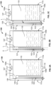
FIGS. 2A-2C are front view of the filtered product bag ofFIG. 1 showing the various steps of a fill, seal and cut process; -
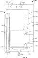
FIG. 3 is a front view of a second embodiment of a filtered product bag constructed in accordance with the principles of the present disclosure; -
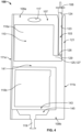
FIG. 4 is a front view of a third embodiment of a filtered product bag constructed in accordance with the principles of the present disclosure; -
FIG. 4A is a front view of the filtered product bag ofFIG. 4 after having been filled, sealed, and cut; -
FIG. 5 is an expanded isometric view of the filter and stem depicted inFIGS. 3 and4 ; -
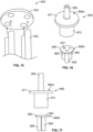
FIG. 6 is a perspective view of an alternative connector for use with a filter and stem such as that disclosed inFIGS. 3-5 ; -
FIG. 7 is a side cross-sectional view of the connector ofFIG. 6 ; -
FIG. 8 is a side view of the connector ofFIG. 6 ; -
FIG. 9 is a bottom view of the connector ofFIG. 8 ; -
FIG. 10 is a top view of the connector ofFIG. 8 ; -
FIG. 11 is a front view of a filter for a sterile product bag having a single looped hollow fiber membrane contained within a filter body; -
FIG. 12 is a front view of a filter for a sterile product bag having a plurality of looped hollow fiber membranes contained within a filter body; -
FIG. 13 is a front view of a plurality of hollow fiber membranes secured side by side; -
FIG. 14 is an isometric view of the securement device used for the plurality of hollow fiber membranes depicted inFIG. 13 ; -
FIG. 15 is an isometric view of a fiber bundle for a product bag having a plurality of hollow fiber membranes secured in a circular holder; -
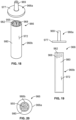
FIG. 16 is an exploded perspective view of an alternative connector for use with a three-filter filter bundle; -
FIG. 17 is a side exploded view of the connector ofFIG. 16 ; -
FIG. 18 is a exploded perspective view of another alternative connector for use with a seven-filter filter bundle; -
FIG. 19 is a side exploded view of the connector ofFIG. 18 ; and -
FIG. 20 is a bottom view of the connector ofFIG. 19 . - The present disclosure is directed to a device and method related to sterilizing and introducing pharmaceutical fluids (e.g., solutions, diluents, drug products, etc.) into a sterile product bag in cost-effective manner. The device includes a product bag constructed of two or more films sealed at a perimeter seal and defining a chamber such as in typical medical grade solution bags. Additionally, however, the product bag includes a sterilizing filtration device such that non-sterile pharmaceutical fluids can be introduced into the product bag in non-traditional environments such as hospitals and/or pharmacies. Uniquely, the filtration device is embedded into the perimeter seal of the product bag in a manner that facilitates filling, and subsequently sealing of the bag, removal and testing of the filter. Embedding the filtration device into the perimeter seal provides a compact configuration which adapts well to conventional manufacturing, sterilizing, shipping, and storage practices.
-
FIGS. 1 and2A-2C illustrate a first embodiment of aproduct bag 100 constructed in accordance with the principles of the present disclosure. Theproduct bag 100 includes abladder 102 and afiltration device 103 embedded into thebladder 102 to provide a compact form factor susceptible to conventional sterilization, shipping, handling, storage, and other procedures. In more detail, one embodiment of thebladder 102 includes at least first and second opposingfilm layers perimeter seal 107 and forming aproduct chamber 110. In other versions, the first and/orsecond film layers product bag 100 against degradation due to light exposure or other environmental concerns. In the depicted version, thebladder 102 is generally rectangular in shape having opposite top and bottomshort sides long sides perimeter seal 107 extends only along thetop side 109a,left side 111a, andbottom side 109b. This is because the depicted version of thebladder 102 is constructed from a single piece of film folded in half at aseam 113 to form theright side 111b. Thus, in this version, the first andsecond film layers perimeter seal 107 can also extend along theseam 113 at theright side 111b of thebladder 102. In still other embodiments, the first andsecond film layers perimeter seal 107 also extends along theright side 111b in order to bond the sheets together to form thechamber 110. As further illustrated inFIG. 1 , theproduct bag 100 can include anopening 117 disposed through theperimeter seal 107 at thetop side 109a and anoutlet port 119 extending through theperimeter seal 107 at thebottom side 109b. Theopening 117 can be for hanging theproduct bag 100, while theoutlet port 119 extends through theperimeter seal 107 in fluid communication with thechamber 110 for delivering contents of the product bag to an administration set during patient administration, for example. - With continued reference to
FIG. 1 and as mentioned, theproduct bag 100 includes thefiltration device 103 embedded in thebladder 102 for a compact product configuration. More particularly, as shown, thefiltration device 103 is embedded into theperimeter seal 107 along theleft side 111a of theproduct bag 100. That is, theperimeter seal 107 at theleft side 111a of theproduct bag 100 includes aretention section 121 that extends from thebottom side 109b to thetop side 109a of thebag 100 and has a length dimension L that is greater than a width dimension W. So configured, theretention section 121 is an elongated section of theperimeter seal 107 having a longitudinal axis A extending along theleft side 111a of theproduct bag 100 parallel to thechamber 110. Theretention section 121 moreover retains thefiltration device 103 within aretention channel 123 defined between the first andsecond film layers perimeter seal 107. Similar to theretention section 121, theretention channel 123 is elongated and extends from thebottom side 109b of theproduct bag 100 almost entirely to thetop side 109a. In the disclosed embodiment, theretention channel 123 extends parallel to and/or co-axial with the longitudinal axis A of theretention section 121. At thebottom side 109b, theretention channel 123 includes aninlet 125 and the opposite end of theretention channel 123 terminates at anoutlet 129. Theoutlet 129 is located at abreak 125 in theperimeter seal 107, which can be referred to as a bridging channel 127 that provides fluid communication between theretention channel 123 and theproduct chamber 110. As can be seen inFIG. 1 , in one embodiment of theproduct bag 100 of the present disclosure, theretention channel 123 is tapered from theinlet 125 to theoutlet 129. That is, a substantial portion of the cross-sectional diameter of theretention channel 123 converges from theinlet 125 to theoutlet 129. This converging or tapered geometry can assist with installing thefiltration device 103 in theretention channel 123 as will be described. - The
filtration device 103 of theproduct bag 100 of the present disclosure can take many different forms suitable to sterilize fluids as they pass through thefiltration device 103 and into theproduct chamber 110. The embodiment of thefiltration device 103 depicted inFIG. 1 is elongated and extends parallel to and/or co-axially with the longitudinal axis A of theretention section 121 of theperimeter seal 107 such that a majority, if not all, of thefiltration device 103 is embedded within theperimeter seal 107. - The
filtration device 103 can include ahousing 104, afilter membrane 170 disposed in-line with thehousing 104, and a sterile closure cap andconnector assembly 108. Thehousing 104 is a hollow narrow tube of uniform diameter fixed in theretention channel 123 of theretention section 121 of theperimeter seal 107. Thehousing 104 includes aninlet 124 disposed in proximity to theinlet 125 of theretention channel 123, and anoutlet 126 disposed in proximity to theoutlet 129 of theretention channel 123. In the depicted version, the sterile closure cap andconnector assembly 108 can be disposed outside of theretention channel 123, as shown, or inside of theretention channel 123. - As mentioned above, the disclosed embodiment of the
retention chamber 123 optionally includes a tapered or convergent geometry. Thus, theinlet 125 of theretention chamber 123 has a diameter that is greater than a diameter of thehousing 104 of thefiltration device 103, and theoutlet 129 of theretention chamber 123 has a diameter that is substantially similar to the diameter of thehousing 104 of thefiltration device 103. Thus, an elongatedannular gap 131 is present between a portion of thefiltration device 103 and an interior wall of theretention chamber 123. An inner diameter of thegap 131 is constant, but an outer diameter of thegap 131 converges from theinlet 125 of theretention chamber 123 toward theoutlet 129, where the diameters of theretention chamber 123 andfiltration device 103 become similar. In the disclosed embodiment, there is aband 133 where thehousing 104 of thefiltration device 103 and theretention chamber 123 have a common diameter and where the two components are bonded together with a hermetic seal, which can be referred to as a port seal. The tapered or convergingretention chamber 123 can assist with inserting thefiltration device 103 into theretention chamber 123. It should be appreciated that in other embodiments, the geometrical relationship between thefiltration device 103 and theretention channel 123 can vary, and a hermetic seal can be provided in order to ensure and maintain a sterile environment within theproduct chamber 110 before, during, and after use of theproduct bag 100. In other embodiments, a mechanical "tack seal" between container the film and theconnector assembly 108 may be formed at theinlet 125 to provide mechanical stability of the container during handling, but a hermetic seal atinlet 125 may not be included or be necessary. In some embodiments, the entirety of theretention chamber 123 andhousing 104 of thefiltration device 103 can share a common diameter and the hermetic seal can extend along the entire length of thefiltration device 103. In such an embodiment, theperimeter seal 107 may be formed for example with thefiltration device 103 already in position between the first andsecond film layers filtration device 103 to be inserted into theretention chamber 123 after theseal 107 has been formed. - So configured, a pharmaceutical fluid such as a water, saline, a solution, a diluent, a final drug product, etc., may enter the
inlet 124 of thehousing 104 through the sterile closure cap andconnector assembly 108, pass through thefilter membrane 170, and beyond theoutlets housing 104 andretention channel 123, respectively, and finally through the bridging channel 127 and into theproduct chamber 110. This filled state of thechamber 110 is depicted schematically inFIG. 2A , for example. As mentioned above, thefilter membrane 170 of thefiltration device 103 is configured to sterilize the pharmaceutical fluid passing into theproduct bag 100. Specific examples of thefilter membrane 170 will be described in more detail below. - It should be appreciated that in the embodiment depicted in
FIGS. 1 and2A-2C , theinlet 124 of thefiltration device 103 is located at thebottom side 109b, which is opposite the hangingopening 117, of theproduct bag 100. This orientation, relative to gravity, can be beneficial when filling theproduct bag 100 with solutions that tend to foam such as certain antibiotics because this bottom fill procedure can reduce aeration during filling. - Once the desired amount of pharmaceutical fluid is introduced into the
chamber 110 of theproduct bag 100 in the manner described, some embodiments of the disclosure may benefit from sealing theproduct chamber 110 off from theretention chamber 123 and optionally cutting thefiltration device 103 away from the bag 109 and performing an integrity test of thefiltration membrane 170. In one embodiment, the next step in the process is to seal thechamber 110 and, more particularly, to seal the first andsecond film layers bridge seal 135, which is illustrated inFIG. 2B . Thebridge seal 135 effectively closes and hermetically seals thechamber 110, protecting the sterility of the fluid disposed therein. - Next, if the process includes testing the
filter membrane 170, a portion of theretention section 121 of theperimeter seal 107, which includes the embeddedfiltration device 103, can be cut off of theproduct bag 100, as shown inFIG. 2C . It is important that the cut occurs along a line L (shown inFIG. 2B ) that is parallel to the longitudinal axis A of theretention section 121 and through a center portion of thebridge seal 135. Theresultant product bag 100 can be seen inFIG. 2C , where a remainingportion 137 of theperimeter seal 107 remains along theleft side 111a of thebladder 102. - As also shown in
FIG. 2C , prior to performing an integrity test on thefilter membrane 170, anend portion 139 of theretention section 121 can be cut away to provide direct exposure to theoutlet 126 of thefiltration device 103. To ensure that thefilter membrane 170 performed properly, and that the fluid in thechamber 110 is sufficiently sterile, a filter integrity test can be performed on thefilter membrane 170. For example, after thefiltration device 103 andretention section 121 are separated from theproduct bag 100, a filter testing device (not shown) may be pre-programmed or controlled to perform a filter integrity test on thefilter membrane 170. Examples of filter integrity tests might include a bubble point test, a pressure degradation test, a water intrusion test, a water flow test, or any suitable test known in the art. A pressure degradation test is a method for testing the quality of a filter either before or after the filter has been used. In the preferred embodiment, thefilter membrane 170 is tested after the solution passes through thefilter membrane 170 and into thebladder 102 of theproduct bag 100. To perform the filter integrity test using a pressure degradation test procedure, a test head (not shown) engages theinlet 124 of thehousing 104 and applies an air pressure of a predetermined value to filtermembrane 170. In one embodiment, the pre-determined value is the pressure where gas cannot permeate thefilter membrane 170. A pressure sensor, or other method of measuring the integrity of the filter, is located within the test head and measures the pressure decay or diffusion rate through thefilter membrane 170. The results from the integrity test are assessed to determine the quality of thefilter membrane 170, and therefore the quality of the solution that previously passed through thefilter membrane 170 and into theproduct bag 100. If the pressure sensor measures a decay or a unexpected rate of decay, then thefilter membrane 170 fails the test and it can be determined that the solution in the product bag is unsatisfactory. Alternatively in a bubble point test, the test head gradually increases the pressure applied to thefilter membrane 170, and the increase in pressure is measured in parallel with the diffusion rate of the gas through thefilter membrane 170. Any disproportionate increase in diffusion rate in relation to the applied pressure may indicate a hole or other structural flaw in thefilter membrane 170, and thefiltration device 103 would fail the integrity test. - Thus, it can be appreciated that the disclosed arrangement of the
retention section 121,filtration device 103, andbridge seal 135 advantageously facilitates the filter integrity test, which allows for a determination to be made with a high degree of certainty that the fluid in the product bag is either sterile or has the potential of being compromised. - The
product bag 100 described with respect toFIGS. 1 and2A-2C is described as including aproduct chamber 110. In some embodiments, theproduct chamber 110 can be completely empty and sterile prior to introducing any pharmaceutical fluid into thechamber 110 through the filtration device 130. In other embodiments, theproduct chamber 110 can be pre-filled with a sterile product concentrate such as a medicament or nutrient concentrate in the form of a powder, a granulate, a gel, a foam, a liquid, etc. In such embodiments, introducing the pharmaceutical fluid into thechamber 110 can include introducing a diluent into thechamber 110 to reconstitute the concentrate into a form that can then be administered to a patient. While theproduct bag 100 inFIGS. 1 and2A-2C is described as including abladder 102 with asingle product chamber 110, other embodiments can include multiple chamber portions. - For example,
FIG. 3 depicts analternative product bag 100 constructed in accordance with the principles of the present disclosure and being substantially similar to theproduct bag 100 described with reference toFIGS. 1 and2A-2C . Thus, for the sake of simplicity, similar components will be identified by similar reference numerals and primarily only the distinctions will be described in any detail. Like theproduct bag 100 ofFIG. 1 , theproduct bag 100 inFIG. 3 includes abladder 102 with aperimeter seal 107 defining aproduct chamber 110. But unlikeFIG. 1 , theproduct chamber 110 of theproduct bag 100 ofFIG. 3 includes first andsecond chamber portions intermediate seal 141 extending between the left andright sides perimeter seal 107. Theintermediate seal 141 is preferably a peel seal that maintains its integrity until a certain hydraulic pressure in thechamber 110 forces the seal to break. That is, thefirst chamber portion 110a is disposed at an upper portion of thechamber 110 in proximity to thetop side 109a of theproduct bag 100, and thesecond chamber portion 110b is disposed at lower portion of thechamber 110 in proximity to thebottom side 109b of theproduct bag 100. So arranged, thefirst chamber portion 110a is in fluid communication with theretention channel 123 andfiltration device 103 by way of the bridge channel 127. In the disclosed embodiment, thesecond chamber portion 110b is also adapted to be in fluid communication with theoutlet port 119 of theproduct bag 100. - With the
product bag 100 arranged as depicted inFIG. 3 , thesecond chamber portion 110 b can be entirely empty or pre-filled with a product concentrate to be reconstituted prior to patient administration. In the pre-filled embodiment, this product concentrate can be filled through aside port 147 in an aseptic filling environment. Theside port 147 extends through theperimeter seal 107 in theright side 111b of theproduct bag 100, and is heat sealed or otherwise permanently bonded closed after filling such that the product concentrate introduced into the second chamber portion remains sterile. - In some embodiments, a
buffer seal 143 can also be provided to seal thesecond chamber portion 110b off from theoutlet port 119 until administration is desired. Thebuffer seal 143 extends across thechamber 110 between portions of theperimeter seal 107 at the left andright sides intermediate seal 141 discussed above, thebuffer seal 143 is preferably a peel seal that maintains its integrity until a certain hydraulic pressure in thechamber 110 forces the seal to break. As can be seen, in some embodiments, the inclusion of abuffer seal 143 results in thechamber 110 of theproduct bag 100 further including abuffer chamber portion 145 disposed below thesecond chamber portion 110b opposite thebuffer seal 143. - Introducing pharmaceutical fluid into the
first chamber portion 110a by way of thefiltration device 103 of theproduct bag 100 ofFIG. 3 occurs in the same manner as introducing fluid into thechamber 100 of theproduct bag 100 ofFIGS. 1 and2A-2C . Thus this process need not be repeated. After fluid resides in thefirst chamber portion 110a, the bridging channel 127 is sealed to form the bridge seal 135 (not shown inFIG. 3 ) and thefilter membrane 170 of thefiltration device 103 is optionally cut off of theproduct bag 100 and tested for integrity. If thefilter membrane 170 passes the integrity test, a user can than reconstitute the product concentrate pre-filled in thesecond chamber portion 110b. This is achieved by manually manipulating the first chamber portion 1110a, which is filled with fluid, to create hydraulic pressures that act on theintermediate seal 141 and ultimately break theintermediate seal 141. When theintermediate seal 141 breaks, the pharmaceutical fluid mixes with the concentrate in thesecond chamber portion 110b to reconstitute the product. Once the product is sufficiently mixed and reconstituted, additional manual manipulation of thechamber 110 can be performed to create hydraulic pressures that act on and break thebuffer seal 143 allowing the product to ultimately flow into and through thebuffer chamber 145 and to theoutlet port 119 for patient administration. As can be appreciated, theproduct bag 100 depicted inFIG. 3 is also a bottom fill bag where theinlet 124 of thefiltration device 103 is located at thebottom side 109b of theproduct bag 100 near theoutlet port 119. As mentioned above with respect toFIGS. 1 and2A-2C , this bottom fill configuration can be beneficial in reducing aeration when introducing pharmaceutical fluids that may have a tendency to foam into theproduct chamber 110. - Advantages of the configuration depicted in
FIGS. 1-3 include elimination of tubing segments on the container and filter assembly, increased pack factor for gamma sterilization of the empty containers, ability to use longer filters for same pack factor to reduce fill time, and elimination of container fill tube vestige. - While
FIGS. 1-3 all depict bottomfill product bags 100, other embodiments can include different configurations. For example,FIGS. 4 and4A depict onealternative product bag 100 including abladder 102 with aperimeter seal 107 and achamber 110 withmultiple chamber portions product bag 100 ofFIG. 3 . As such, those aspects will not be repeated. UnlikeFIG. 3 , however, the product bag ofFIG. 4 includes thefiltration device 103 being arranged in a manner that itsinlet 124 is disposed on thetop side 109a of thebag 100 in proximity to thehanger opening 117 and opposite theoutlet port 119. Moreover, as depicted inFIG. 4 , theretention section 121 of theperimeter seal 107, which retains thefiltration device 103, is disposed on theright side 111b of thebag 100. But this is merely a product of the orientation of the bag inFIG. 4 . Further, thefiltration device 103 inFIG. 4 is depicted as having a shorter longitudinal dimension than inFIGS. 1-3 because theoutlet 126 of thefiltration device 103 must align with theoutlet 129 of theretention channel 123 and bridging channel 127 to communicate with thefirst chamber portion 110a. All other aspects of the relationship between thefiltration device 103,retention section 121, andretention channel 123 remain the same as that described above with respect to the same components inFIGS. 1-3 . For example, filling of thefirst chamber portion 110a is achieved by introducing fluid through thefiltration device 103. Then the bridging channel 127 can be sealed to form abridge seal 135. For testing the integrity of thefiltration device 103, theretention section 121 of theperimeter seal 107 containing thefiltration device 103 can be cut off of the product bag along line L located between theretention channel 123 and thechamber 110 such that thechamber 110 remains sealed, as shown inFIG. 4A . Finally, before thefiltration device 103 can be integrity tested, a portion of theretention section 121 located beyond theoutlet 126 of the filtration device 130 must be cut off, as depicted inFIG. 4A , to expose theoutlet 126 and facilitate the testing procedure as described above. While the top-fill bag 100 ofFIG. 4 is depicted as having achamber 110 with multiple chamber portions, alternative embodiments of the bag can have a single chamber such as inFIG. 1 . The remainder of the reconstitution and administration process for theproduct bag 100 inFIGS. 4 and4A is identical to that described above with respect toFIG. 3 . Although not expressly depicted, the scope of the disclosure also includes single chamber top-fill product bags 100 with thefiltration device 103 embedded as described herein. - As mentioned, the
filter membrane 170 of thefiltration device 103 of the present disclosure is configured to sterilize fluid as is passes through thefiltration device 103 and into theproduct bag 100. So configured, the sterile fluid in theproduct bag 100 can be subsequently administered directly to a patient. Thefiltration device 103 and thefilter membrane 170 can take many different forms and the scope of the present disclosure is not necessarily limited to any one or more. - For example,
FIG. 5 depicts one embodiment of thefiltration device 103 where thehousing 104 comprises astem 156, and ahollow connector 166 is used to secure thestem 156 and thefilter membrane 170 together. Theconnector 166 can be part of, or coupled to, the sterile closure cap andconnector assembly 108 described above inFIGS. 1-4 . Thefilter membrane 170 includes anopen inlet end 160 sealingly connected to anopen outlet end 168 of thehollow connector 166. The connection may be achieved by gluing theopen inlet end 160 of thefilter membrane 170 to theopen outlet end 168 of theconnector 166 with, for example, an epoxy resin, a polyurethane resin, a cyanoacrylate resin, a UV curing acrylic adhesive, or a solvent for the material of thehollow connector 166 such as cyclohexanone. In the version depicted, theopen outlet end 168 of theconnector 166 comprises a hollow cylindrical member that fits inside of and is fixed to theopen inlet end 160 of thefilter membrane 170. As such, an outer diameter of theopen outlet end 168 of theconnector 166 is substantially similar to or slightly smaller than an inner diameter of theopen inlet end 160 of thefilter membrane 170. In some versions, theopen inlet end 160 of thefilter membrane 170 may be welded to theopen outlet end 168 of theconnector 166 by, for example, heat welding (e.g., introducing a hot conical metal tip into the open inlet end 150 of thefilter membrane 170 to partially melt it), laser welding if thehollow connector 166 is made from a material that absorbs laser radiation, mirror welding, ultrasound welding, and friction welding. Alternately, thefilter membrane 170 may be inserted into a mold, and a thermoplastic polymer may be injection-molded around it to form thehollow connector 166. Other designs and configurations for connecting thefilter membrane 170 to theconnector 166 are intended to be within the scope of the present disclosure. - The
hollow connector 166 further includes afluid inlet 169. A pharmaceutical fluid can be fed via a connected fluid supply line, for example, into thefluid inlet 169 of thehollow connector 166. In some versions, thefluid inlet 169 can include a Luer type fitting or other standard medical fitting. The pharmaceutical fluid can then travel through thehollow connector 166 and exit into thefilter membrane 170 through theopen outlet end 168 of thehollow connector 166. Thehollow connector 166 also includes a sealingsurface 172 to which thestem 156 is attached. The sealingsurface 172 in this version is cylindrical and has a diameter larger than a diameter of theopen outlet end 168, and is disposed generally concentric with theopen outlet end 168. In fact, in this version, the outer diameter of the sealingsurface 172 is generally identical to or slightly smaller than an inner diameter of thestem 156. So configured, thestem 156 receives the sealingsurface 172 and extends therefrom to surround and protect thefilter membrane 170 without contacting thesurface 164 of thefilter membrane 170. Thestem 156 can be fixed to the sealingsurface 172 with adhesive (e.g., a UV curing acrylic adhesive), epoxy, welding, bonding, etc. Thestem 156 receives the pharmaceutical solution after it passes through thepores 162 in thefilter membrane 170. From there, the now filtered solution passes into the bladder. -
FIGS. 6-10 illustrate an alternativehollow connector 766, similar toconnector 166, for securing thestem 156 and the hollowfiber filter membrane 170 ofFIGS. 3-5 together. Theconnector 766 includes anopen outlet end 768 carried by a stem structure that extends in a first direction from abearing plate 777 and is adapted to be sealingly connected to theopen inlet end 160 of thefilter membrane 170. The connection may be achieved by gluing theopen inlet end 160 of thefilter membrane 170 to theopen outlet end 768 of theconnector 766 with, for example, an epoxy resin, a polyurethane resin, a cyanoacrylate resin, a UV curing acrylic adhesive, or a solvent for the material of thehollow connector 766 such as cyclohexanone. In the version depicted, the stem structure of theopen outlet end 768 of theconnector 766 comprises a hollow cylindrical member that fits inside of and is fixed to theopen inlet end 160 of thefilter membrane 170. As such, an outer diameter of theopen outlet end 768 of theconnector 766 is substantially similar to or slightly smaller than an inner diameter of theopen inlet end 160 of thefilter membrane 170. In some versions, theopen inlet end 160 of thefilter membrane 170 may be welded to theopen outlet end 768 of theconnector 766 by, for example, heat welding (e.g., introducing a hot conical metal tip into the open inlet end 150 of thefilter membrane 170 to partially melt it), laser welding if thehollow connector 766 is made from a material that absorbs laser radiation, mirror welding, ultrasound welding, and friction welding. Alternately, thefilter membrane 170 may be inserted into a mold, and a thermoplastic polymer may be injection-molded around it to form thehollow connector 766. Other designs and configurations for connecting thefilter membrane 170 to theconnector 766 are intended to be within the scope of the present disclosure. - The
hollow connector 766 further includes afluid inlet 769, which is also a stem structure, extending in a second direction (opposite the first direction) from the bearingplate 777. A pharmaceutical fluid can be fed via a connected fluid supply line, for example, into thefluid inlet 769 of thehollow connector 766. In some versions, thefluid inlet 769 can include a Luer type fitting or other standard medical fitting. The pharmaceutical fluid can then travel through thehollow connector 766 and exit into thefilter membrane 170 through theopen outlet end 768 of thehollow connector 766. - The
hollow connector 766 also includes a sealingsurface 772 to which thestem 156 is attached. The sealingsurface 772 in this version is a cylindrical shroud extending from the bearingplate 777 in the first direction and has a diameter larger than a diameter of theopen outlet end 768. The sealingsurface 772 is disposed generally concentric with theopen outlet end 768. As such, in this embodiment, the shroud of the sealingsurface 772 surrounds the stem structure of theopen outlet end 768 such that anannular gap 779 resides between the two. In fact, in this version, the outer diameter of the sealingsurface 772 is generally identical to or slightly smaller than an inner diameter of thestem 156. So configured, the sealingsurface 772 of theconnector 766 can be received by thestem 156 such that thestem 156 extends therefrom to surround and protect thefilter membrane 170 without contacting thesurface 164 of thefilter membrane 170. Thestem 156 can be fixed to the sealingsurface 772 with adhesive (e.g., a UV curing acrylic adhesive), epoxy, welding, bonding, etc. Thestem 156 receives the pharmaceutical fluid after it passes through thepores 162 in thefilter membrane 170. From there, the now filtered fluid passes into theproduct bag 100 of any ofFIGS. 1-4 . - While the foregoing version of the
filter membrane 170 has been described as including asingle filter membrane 170, in other embodiments within the scope of the present disclosure, thefilter membrane 170 may includemultiple filter membranes 170. A few nonlimiting examples of multiple membrane filters will be discussed below. Finally, in some embodiments, theconnector 166 inFIG. 5 can include asterile closure cap 154 covering thesolution inlet 168 to prevent contaminants from entering the product bag prior to being filled. - In one version of the foregoing assembly of
FIG. 5 , and as mentioned, thestem 156 includes an inner diameter that is larger than an outer diameter of thefilter membrane 170, and thestem 156 includes a longitudinal dimension that is larger than a longitudinal dimension of thefilter membrane 170. As such, when thestem 156 andfilter membrane 170 are assembled onto theconnector 166, thefilter membrane 170 resides entirely within (i.e., entirely inside of) thestem 156 and a gap exists between the inner sidewall of thestem 156 and the outer sidewall of thefilter membrane 170. As such, fluid passing into thefilter membrane 170 passes out of the plurality ofpores 162 and flows without obstruction through the gap and along the inside of thestem 156 to the bladder. In some versions, thestem 156 can be a flexible tube, a rigid tube, or can include a tube with portions that are flexible and other portions that are rigid. Specifically, in some versions, astem 156 with at least a rigid portion adjacent to thefilter membrane 170 can serve to further protect thefilter membrane 170 and/or prevent thefilter membrane 170 from becoming pinched or kinked in a flexible tube. In other versions, such protection may not be needed or desirable. In one embodiment, thestem 156 has an internal diameter in the range of approximately 2.5 mm to approximately 8 mm, and a longitudinal dimension in the range of approximately 5 cm to approximately 30 cm. In one embodiment, the internal diameter of thestem 156 is about 0.2 to about 3 mm larger than the outer diameter of thefilter membrane 170. And, thefilter membrane 170 has an outer diameter in the range of approximately 2.3 mm to approximately 5 mm, a longitudinal dimension in the range of approximately 3 cm to approximately 420 cm, and a wall thickness in the range of approximately 150 µm to approximately 500 µm. Furthermore, in one version each of the plurality ofpores 162 in thefilter membrane 170 have a diameter less than or equal to approximately 0.2 microns. In some versions, each pore has a diameter less than or equal to a value in a range of approximately 0.1 microns to approximately 0.5 microns, for instance, approximately 0.2 to approximately 0.4 microns. In some versions, each pore has a diameter that is less than or equal to approximately 0.22 microns. In some versions, each pore has a diameter that is less than or equal to a value in a range of approximately 0.1 microns to approximately 0.2 microns. In some versions, each pore has a diameter that is less than or equal to a value in a range of approximately 0.1 microns to approximately 0.22 microns. These pore sizes coupled with the disclosed geometrical dimension of thestem 156 andfilter membrane 170 ensure acceptable flow rates through thefilter membrane 170 for filling the product bags with patient injectable solutions such as sterile water, sterile saline, etc. In other versions, any or all of the dimensions could vary depending on the specific application. - Suitable materials for the
filter membrane 170 can include polyolefins (e.g., PE, PP), polyvinylidene fluoride, polymethylmethacrylate, polyacrylonitrile, polysulfone, and polyethersulfone. In some embodiments within the scope of the present disclosure, thefilter membrane 170 may be comprised of a blend of polysulfone or polyethersulfone and polyvinylpyrrolidone. In other embodiments within the scope of the present disclosure, thefilter membrane 170 can include a polymer containing cationic charges, e.g. polymers bearing functional groups like quaternary ammonium groups. A suitable example for such polymers is polyethyleneimine. Thefilter membrane 170 may be manufactured by known techniques including, e.g., extrusion, phase inversion, spinning, chemical vapor deposition, 3D printing, etc. Suitable materials for thestem 156 include PVC, polyesters like PET, poly(meth)acrylates like PMMA, polycarbonates (PC), polyolefins like PE, PP, or cycloolefin copolymers (COC), polystyrene (PS), silicone polymers, etc. - Additional details regarding some possible versions of the filter and the specific construction of the membrane, for example, can be found in European Patent Application No.
EP16152332.9, entitled FILTER MEMBRANE AND DEVICE, filed January 22, 2016 PCT/EP2017/051044, entitled FILTER MEMBRANE AND DEVICE, filed January 19, 2017 - Thus far, the
hollow fiber membrane 170 inFIG. 5 , for example, has been described as being located within thestem 156. In other embodiments, thefilter membrane 170 may include its own housing or other support structure, which is coupled to thestem 156 either in place of theconnector 166 inFIG. 5 orconnector 766 inFIGS. 6-10 , or at a location between two portions of thestem 156. - For example,
FIG. 11 is a front view of afilter assembly 1000 for a product bag (not pictured) having a single U-shaped hollowfiber filter membrane 1002 contained within afilter body 1004. Thefilter membrane 1002 is secured to afilter membrane housing 1006 in the U-shaped configuration with an adhesive (i.e., a UV curing acrylic adhesive), an epoxy, welding, bonding, or other means. Thefilter membrane housing 1006 is connected to thefilter body 1004 at anoutlet portion 1008 of thefilter body 1004. Aninlet portion 1010 is sealably connected to theoutlet portion 1008 of thefilter body 1004 at a joint or other seam. Theinlet portion 1010 of thefilter body 1004 has aninlet 1012 by which a pharmaceutical fluid may enter thefilter assembly 1000. The pharmaceutical fluid then enters thefilter membrane 1002 through a plurality ofpores 1014, travels through thefilter membrane 1002, exits thefilter membrane 1002 atfilter membrane outlets 1016, and exits thefilter body 1004 atfilter outlet 1018. The filter outlet 418 may then be connected to the bladder (not pictured) via the stem 256 of a product bag (not pictured). InFIG. 11 , the flow of fluid through theassembly 1000 has been described as moving from theinlet 1012 of theinlet portion 1010 to theoutlet 1018 of theoutlet portion 1008. However, the same assembly 400 could be used in the opposite direction such that fluid enters the outlet1018 of theoutlet portion 1008 and exits theinlet 1012 of theinlet portion 1010. In this alternative configuration, fluid would first enter theinlet 1018, pass into thefilter membrane 1002 at thefilter membrane outlets 1016, and exit through thepores 1014 and finally theinlet 1012. -
FIG. 12 is an alternate embodiment of thefilter assembly 1000 depicted inFIG. 11 . InFigure 12 , thefilter 1020 includes two U-shaped hollowfiber filter membranes 1022 are secured to afilter membrane housing 1024 in the U-shaped configuration with an adhesive (i.e., a UV curing acrylic adhesive), an epoxy, welding, bonding, or some other means. Thefilter membranes 1022 and filtermembrane housing 1024 are contained within afilter body 1026 having aninlet portion 1028 withinlet 1030 sealably connected to anoutlet portion 1032 havingfilter outlet 1034. In other embodiments, a filter may include more than two U-shaped hollow fiber filter membranes arranged as depicted inFIGS. 11 and 12 . InFIG. 12 , like inFIG. 11 , the flow of fluid through theassembly 1000 has been described as moving from theinlet portion 1028 to theoutlet portion 1032. However, thesame assembly 1000 could be used in the opposite direction such that fluid enters theoutlet portion 1032 and exits theinlet portion 1028 as described above relative toFIG. 11 . -
FIG. 13 is a further alternative filter assembly. Specifically, inFig. 13 , a plurality of linear membrane filters 502 are secured directly together in a parallel side-by-side configuration for what can be referred to as a fiber bundle. Thefilters 502 inFIG. 13 can be secured together with adhesive (i.e., a UV curing acrylic adhesive), epoxy, welding, bonding, etc. In other versions, the plurality offilters 502 can be manufactured together as one piece by way of any of the manufacturing techniques described above. -
FIG. 14 provides another alternative in which asecurement device 504 includes a number of blocks defining a plurality ofgrooves 506 identical to the number of hollow fiber membrane filters 502. The blocks of thesecurement device 504 may be sandwiched together and used to hold the plurality of hollowfiber membrane filters 502 in the side-by-side configuration. Thesecurement device 504 depicted inFIG. 14 allows for two sets of the hollowfiber membrane filters 502 ofFIG. 13 to be stacked relative to each other. The fiber bundle including the membrane filters 502 and thesecurement device 504 may be placed in a filter body, such as that discussed with respect toFIGS. 11 and 12 . -
FIG. 15 is an isometric view of another version of afiber bundle 600 for a product bag (not pictured) having a plurality of parallel hollow fiber membrane filters 502 similar toFIGS. 13 and 14 , but wherein theparallel filters 502 are arranged in a circular pattern by acircular holder 504. Thefiber bundle 600 may be placed in a filter body, such as that discussed with respect toFIGS. 11 and 12 . -
FIGS. 16-17 andFIGS. 18-20 illustrate two additional devices for coupling fiber bundles to a stem in accordance with the present disclosure.FIGS. 16-17 discloses aconnector 866 for connecting a three-fiber bundle to a stem. Specifically, theconnector 866 includes a firsthollow body 866a and a secondhollow body 866b. Thefirst body 866a includes asolution inlet 869, which is a stem structure, extending from abearing plate 877. A pharmaceutical fluid can be fed via a connected fluid supply line, for example, into thefluid inlet 869 of the firsthollow body 866a of theconnector 866. In some versions, thefluid inlet 869 can include a Luer type fitting or other standard medical fitting. - The
hollow connector 866 also includes a sealingsurface 872 to which thestem 156 is attached. The sealingsurface 872 in this version is a cylindrical shroud extending from the bearingplate 877 in a direction opposite to a direction of extension of thefluid inlet 869. The sealingsurface 872 is disposed generally concentric with thefluid inlet 869. As such, in this embodiment, the shroud of the sealingsurface 872 defines a cylindrical cavity (not shown in the drawings) for receiving a portion of the secondhollow body 866b of theconnector 866. - The second
hollow body 866b, as depicted, includes asupport plate 880 and three open outlet ends 868 extending from thesupport plate 880. Additionally, thesupport plate 880 includes an outer diameter that is essentially the same as or slightly smaller than an inner diameter of the cavity of the shroud of the sealingsurface 872 such that when assembled, thesupport plate 880 is positioned into the cavity. In one version, thesupport plate 880 includes aseal member 882 around its periphery to form a fluid tight seal with the inner surface of the shroud of the sealingsurface 872 when inserted into the cavity. Friction, adhesive, or some other means may retain thesupport plate 880 in connection with the shroud of the sealingsurface 872. - As mentioned, the
second body 866b includes three open outlet ends 868 extending from thesupport plate 880. Eachopen outlet end 868 is adapted to be sealingly connected to anopen inlet end 160 of one of threefilters 155. The connection may be achieved by gluing open inlet ends 160 of thefilters 155 to the open outlet ends 868 with, for example, an epoxy resin, a polyurethane resin, a cyanoacrylate resin, a UV curing acrylic adhesive, or a solvent for the material of thehollow connector 766 such as cyclohexanone. In the version depicted, the stem structure of the open outlet ends 868 of theconnector 866 comprises a hollow cylindrical member that fits inside of and is fixed to the open inlet ends 160 of thefilters 155. As such, an outer diameter of the open outlet ends 868 is substantially similar to or slightly smaller than an inner diameter of the open inlet ends 160 of thefilters 155. In some versions, thefilters 155 may be welded to the open outlet ends 868 of theconnector 866 by, for example, heat welding (e.g., introducing a hot conical metal tip into the open inlet ends 150 of thefilters 155 to partially melt it), laser welding if thehollow connector 866 is made from a material that absorbs laser radiation, mirror welding, ultrasound welding, and friction welding. Alternately, thefilters 155 may be inserted into a mold, and a thermoplastic polymer may be injection-molded around it to form thehollow connector 866. Other designs and configurations for connecting thefilters 155 to the open outlet ends 868 are intended to be within the scope of the present disclosure. - Finally, as with previously described embodiments, the sealing
surface 872 of theconnector 866 can be received by thestem 156 such that thestem 156 extends therefrom to surround and protect thefilters 155 without contacting thesurfaces 164 of thefilters 155. Thestem 156 can be fixed to the sealingsurface 872 with adhesive (e.g., a UV curing acrylic adhesive), epoxy, welding, bonding, etc. Thestem 156 receives the pharmaceutical solution after it passes through thepores 162 in thefilter membrane 170. From there, the now filtered solution passes into the bladder in the same manner described above with respect toFIGS. 3-5 . -
FIGS. 18-20 discloses aconnector 966 for connecting a seven-fiber bundle to a stem. Specifically, theconnector 966 includes a firsthollow body 966a and a secondhollow body 966b that can be connected to the firsthollow body 966a with an adhesive or via other means. Thefirst body 966a includes asolution inlet 969, which is a stem structure, extending from abearing plate 977. A pharmaceutical fluid can be fed via a connected fluid supply line, for example, into thefluid inlet 969 of the firsthollow body 966a of theconnector 966. In some versions, thefluid inlet 969 can include a Luer type fitting or other standard medical fitting. - The second
hollow body 966b, as depicted, includes a hollowcylindrical support collar 980 in which seven hollowfiber membrane filters 955 can be disposed parallel to each other, as shown inFIGS. 18 and 20 . In one version, thesupport collar 980 can include asupport plate 982 carrying seven open outlet ends 968 extending into thecollar 980 for connecting to thefilters 955 in a manner similar to that described above regardingFIGS. 16-17 . The connection may be achieved by gluing thefilters 955 to the open outlet ends 968 with, for example, an epoxy resin, a polyurethane resin, a cyanoacrylate resin, a UV curing acrylic adhesive, or a solvent for the material of thehollow connector 966 such as cyclohexanone. In the version depicted, the stem structure of the open outlet ends 868 of theconnector 866 comprises a hollow cylindrical member that fits inside of and is fixed to thefilters 955. As such, a diameter of the open outlet ends 968 is substantially similar to or slightly smaller than an inner diameter of thefilters 955. In some versions, thefilters 955 may be welded to the open outlet ends 968 of theconnector 966 by, for example, heat welding (e.g., introducing a hot conical metal tip into thefilters 955 to partially melt it), laser welding if thehollow connector 966 is made from a material that absorbs laser radiation, mirror welding, ultrasound welding, and friction welding. Alternately, thefilters 955 may be inserted into a mold, and a thermoplastic polymer may be injection-molded around it to form thehollow connector 966. Other designs and configurations for connecting thefilters 955 to the open outlet ends 968 are intended to be within the scope of the present disclosure. - Finally, the
collar 980 of this embodiment includes a sealingsurface 972 that can be received by thestem 156 such that thestem 156 extends therefrom. Thestem 156 can be fixed to the sealingsurface 972 with adhesive (e.g., a UV curing acrylic adhesive), epoxy, welding, bonding, etc. Thestem 156 receives the pharmaceutical fluid after it passes through thepores 162 in thefilters 955. From there, the now filtered fluid passes into the bladder in the same manner described above with respect toFIGS. 3-5 . - From the foregoing, it can be seen that various filtering arrangements can serve the principles of the present disclosure including introducing fluid to the product bag in a sterilized manner. While certain representative versions of the claimed subject matter have been described herein for purposes of illustrating the invention, it will be apparent to those skilled in the art that various changes in the devices and methods disclosed may be made without departing from the scope of the appended claims.
Claims (6)
- A method of sterilizing and introducing fluid into a product bag (100), the method comprising:providing a bladder (102) comprising opposing first and second film layers (105a, 105b) defining a sterile product chamber (110), the first and second film layers sealed together along a perimeter seal (107) extending along at least a portion of a perimeter of the bladder, the perimeter seal including at least one break defining a bridging channel (127) in fluid communication with the sterile product chamber;providing a sterilizing filtration device (103) embedded in the perimeter seal (107), the filtration device (103) having an inlet end (124) adapted for receiving a fluid to be sterilized, and an outlet end (126) in fluid communication with the sterile product chamber via the bridging channel, the filtration device having a filter membrane (170, 1002, 1022) with a nominal pore size in a range of approximately 0.1 µm to approximately 0.5 µm;introducing a pharmaceutical fluid into the sterile product chamber through the filtration device and bridging channel such that a sterile pharmaceutical fluid resides within the sterile product chamber; andsealing the opposing first and second layer films together across the bridging channel to create a bridge seal (135) to maintain the sterilized pharmaceutical fluid in the sterile product chamber.
- The method of claim 1, further comprising cutting the filtration device off of the product bag.
- The method of claim 2, wherein cutting the filtration device off of the product bag comprises cutting across the bridging seal.
- The method of claim 2 or 3, further comprising performing a filter integrity test on the filter membrane after cutting the filtration device off of the product bag.
- The method of claim 4, wherein performing the filter integrity test comprises performing one of a pressure degradation test, a bubble point test, a water intrusion test, or a water flow test.
- The method of any one of claims 1 to 5, wherein introducing the pharmaceutical fluid into the sterile product chamber through the filtration device comprises introducing the pharmaceutical fluid through a plurality of filter membranes.
Applications Claiming Priority (2)
| Application Number | Priority Date | Filing Date | Title |
|---|---|---|---|
| US201762533427P | 2017-07-17 | 2017-07-17 | |
| PCT/US2018/041809 WO2019018202A1 (en) | 2017-07-17 | 2018-07-12 | Product bag with integral filter |
Publications (2)
| Publication Number | Publication Date |
|---|---|
| EP3655045A1 EP3655045A1 (en) | 2020-05-27 |
| EP3655045B1 true EP3655045B1 (en) | 2024-07-03 |
Family
ID=63036520
Family Applications (1)
| Application Number | Title | Priority Date | Filing Date |
|---|---|---|---|
| EP18746548.9A Active EP3655045B1 (en) | 2017-07-17 | 2018-07-12 | Method of sterilizing and introducing fluid into a product bag |
Country Status (5)
| Country | Link |
|---|---|
| US (1) | US11511009B2 (en) |
| EP (1) | EP3655045B1 (en) |
| AU (1) | AU2018304077B2 (en) |
| CA (1) | CA3070399A1 (en) |
| WO (1) | WO2019018202A1 (en) |
Families Citing this family (1)
| Publication number | Priority date | Publication date | Assignee | Title |
|---|---|---|---|---|
| CA3201044A1 (en) | 2020-12-28 | 2022-07-07 | Gianni Di Stefani | Method and system for producing sterile solution filled containers |
Family Cites Families (3)
| Publication number | Priority date | Publication date | Assignee | Title |
|---|---|---|---|---|
| FR2389383A1 (en) * | 1977-05-04 | 1978-12-01 | Johnson & Johnson | |
| CA2444590C (en) | 2001-04-18 | 2009-12-01 | Robert L. Mcginnis | Stabilized hemoglobin solutions |
| EP2684551B1 (en) * | 2011-03-09 | 2021-10-06 | Terumo Kabushiki Kaisha | System for delivering oxygen carrier, oxygenation device for oxygen carrier, and housing for oxygen carrier |
-
2018
- 2018-07-12 CA CA3070399A patent/CA3070399A1/en active Pending
- 2018-07-12 US US16/631,067 patent/US11511009B2/en active Active
- 2018-07-12 EP EP18746548.9A patent/EP3655045B1/en active Active
- 2018-07-12 WO PCT/US2018/041809 patent/WO2019018202A1/en not_active Ceased
- 2018-07-12 AU AU2018304077A patent/AU2018304077B2/en active Active
Also Published As
| Publication number | Publication date |
|---|---|
| CA3070399A1 (en) | 2019-01-24 |
| AU2018304077A1 (en) | 2020-02-06 |
| AU2018304077B2 (en) | 2023-01-12 |
| US20200147251A1 (en) | 2020-05-14 |
| EP3655045A1 (en) | 2020-05-27 |
| US11511009B2 (en) | 2022-11-29 |
| WO2019018202A1 (en) | 2019-01-24 |
Similar Documents
| Publication | Publication Date | Title |
|---|---|---|
| US11564867B2 (en) | Sterile solutions product bag | |
| US11759395B2 (en) | Dual container system for product reconstitution | |
| US11974966B2 (en) | Medical product including pre-filled product bag | |
| AU2018304077B2 (en) | Product bag with integral filter | |
| EP3655067B1 (en) | Medical syringe system with filtered filling port |
Legal Events
| Date | Code | Title | Description |
|---|---|---|---|
| STAA | Information on the status of an ep patent application or granted ep patent |
Free format text: STATUS: UNKNOWN |
|
| STAA | Information on the status of an ep patent application or granted ep patent |
Free format text: STATUS: THE INTERNATIONAL PUBLICATION HAS BEEN MADE |
|
| PUAI | Public reference made under article 153(3) epc to a published international application that has entered the european phase |
Free format text: ORIGINAL CODE: 0009012 |
|
| STAA | Information on the status of an ep patent application or granted ep patent |
Free format text: STATUS: REQUEST FOR EXAMINATION WAS MADE |
|
| 17P | Request for examination filed |
Effective date: 20200123 |
|
| AK | Designated contracting states |
Kind code of ref document: A1 Designated state(s): AL AT BE BG CH CY CZ DE DK EE ES FI FR GB GR HR HU IE IS IT LI LT LU LV MC MK MT NL NO PL PT RO RS SE SI SK SM TR |
|
| AX | Request for extension of the european patent |
Extension state: BA ME |
|
| DAV | Request for validation of the european patent (deleted) | ||
| DAX | Request for extension of the european patent (deleted) | ||
| STAA | Information on the status of an ep patent application or granted ep patent |
Free format text: STATUS: EXAMINATION IS IN PROGRESS |
|
| 17Q | First examination report despatched |
Effective date: 20220209 |
|
| REG | Reference to a national code |
Ref country code: DE Ref legal event code: R079 Free format text: PREVIOUS MAIN CLASS: A61L0002260000 Ipc: A61L0002020000 Ref document number: 602018071289 Country of ref document: DE |
|
| GRAP | Despatch of communication of intention to grant a patent |
Free format text: ORIGINAL CODE: EPIDOSNIGR1 |
|
| STAA | Information on the status of an ep patent application or granted ep patent |
Free format text: STATUS: GRANT OF PATENT IS INTENDED |
|
| RIC1 | Information provided on ipc code assigned before grant |
Ipc: B65B 3/00 20060101ALI20240125BHEP Ipc: A61J 1/14 20060101ALI20240125BHEP Ipc: A61L 2/26 20060101ALI20240125BHEP Ipc: A61L 2/02 20060101AFI20240125BHEP |
|
| INTG | Intention to grant announced |
Effective date: 20240215 |
|
| GRAS | Grant fee paid |
Free format text: ORIGINAL CODE: EPIDOSNIGR3 |
|
| GRAA | (expected) grant |
Free format text: ORIGINAL CODE: 0009210 |
|
| STAA | Information on the status of an ep patent application or granted ep patent |
Free format text: STATUS: THE PATENT HAS BEEN GRANTED |
|
| AK | Designated contracting states |
Kind code of ref document: B1 Designated state(s): AL AT BE BG CH CY CZ DE DK EE ES FI FR GB GR HR HU IE IS IT LI LT LU LV MC MK MT NL NO PL PT RO RS SE SI SK SM TR |
|
| REG | Reference to a national code |
Ref country code: CH Ref legal event code: EP |
|
| REG | Reference to a national code |
Ref country code: DE Ref legal event code: R096 Ref document number: 602018071289 Country of ref document: DE |
|
| REG | Reference to a national code |
Ref country code: LT Ref legal event code: MG9D |
|
| REG | Reference to a national code |
Ref country code: NL Ref legal event code: MP Effective date: 20240703 |
|
| PG25 | Lapsed in a contracting state [announced via postgrant information from national office to epo] |
Ref country code: PT Free format text: LAPSE BECAUSE OF FAILURE TO SUBMIT A TRANSLATION OF THE DESCRIPTION OR TO PAY THE FEE WITHIN THE PRESCRIBED TIME-LIMIT Effective date: 20241104 |
|
| REG | Reference to a national code |
Ref country code: AT Ref legal event code: MK05 Ref document number: 1699130 Country of ref document: AT Kind code of ref document: T Effective date: 20240703 |
|
| PG25 | Lapsed in a contracting state [announced via postgrant information from national office to epo] |
Ref country code: NL Free format text: LAPSE BECAUSE OF FAILURE TO SUBMIT A TRANSLATION OF THE DESCRIPTION OR TO PAY THE FEE WITHIN THE PRESCRIBED TIME-LIMIT Effective date: 20240703 |
|
| PG25 | Lapsed in a contracting state [announced via postgrant information from national office to epo] |
Ref country code: PT Free format text: LAPSE BECAUSE OF FAILURE TO SUBMIT A TRANSLATION OF THE DESCRIPTION OR TO PAY THE FEE WITHIN THE PRESCRIBED TIME-LIMIT Effective date: 20241104 Ref country code: NL Free format text: LAPSE BECAUSE OF FAILURE TO SUBMIT A TRANSLATION OF THE DESCRIPTION OR TO PAY THE FEE WITHIN THE PRESCRIBED TIME-LIMIT Effective date: 20240703 |
|
| PG25 | Lapsed in a contracting state [announced via postgrant information from national office to epo] |
Ref country code: NO Free format text: LAPSE BECAUSE OF FAILURE TO SUBMIT A TRANSLATION OF THE DESCRIPTION OR TO PAY THE FEE WITHIN THE PRESCRIBED TIME-LIMIT Effective date: 20241003 |
|
| PG25 | Lapsed in a contracting state [announced via postgrant information from national office to epo] |
Ref country code: GR Free format text: LAPSE BECAUSE OF FAILURE TO SUBMIT A TRANSLATION OF THE DESCRIPTION OR TO PAY THE FEE WITHIN THE PRESCRIBED TIME-LIMIT Effective date: 20241004 Ref country code: FI Free format text: LAPSE BECAUSE OF FAILURE TO SUBMIT A TRANSLATION OF THE DESCRIPTION OR TO PAY THE FEE WITHIN THE PRESCRIBED TIME-LIMIT Effective date: 20240703 Ref country code: PL Free format text: LAPSE BECAUSE OF FAILURE TO SUBMIT A TRANSLATION OF THE DESCRIPTION OR TO PAY THE FEE WITHIN THE PRESCRIBED TIME-LIMIT Effective date: 20240703 |
|
| PG25 | Lapsed in a contracting state [announced via postgrant information from national office to epo] |
Ref country code: BG Free format text: LAPSE BECAUSE OF FAILURE TO SUBMIT A TRANSLATION OF THE DESCRIPTION OR TO PAY THE FEE WITHIN THE PRESCRIBED TIME-LIMIT Effective date: 20240703 |
|
| PG25 | Lapsed in a contracting state [announced via postgrant information from national office to epo] |
Ref country code: LV Free format text: LAPSE BECAUSE OF FAILURE TO SUBMIT A TRANSLATION OF THE DESCRIPTION OR TO PAY THE FEE WITHIN THE PRESCRIBED TIME-LIMIT Effective date: 20240703 |
|
| PG25 | Lapsed in a contracting state [announced via postgrant information from national office to epo] |
Ref country code: IS Free format text: LAPSE BECAUSE OF FAILURE TO SUBMIT A TRANSLATION OF THE DESCRIPTION OR TO PAY THE FEE WITHIN THE PRESCRIBED TIME-LIMIT Effective date: 20241103 Ref country code: AT Free format text: LAPSE BECAUSE OF FAILURE TO SUBMIT A TRANSLATION OF THE DESCRIPTION OR TO PAY THE FEE WITHIN THE PRESCRIBED TIME-LIMIT Effective date: 20240703 |
|
| PG25 | Lapsed in a contracting state [announced via postgrant information from national office to epo] |
Ref country code: HR Free format text: LAPSE BECAUSE OF FAILURE TO SUBMIT A TRANSLATION OF THE DESCRIPTION OR TO PAY THE FEE WITHIN THE PRESCRIBED TIME-LIMIT Effective date: 20240703 Ref country code: CZ Free format text: LAPSE BECAUSE OF FAILURE TO SUBMIT A TRANSLATION OF THE DESCRIPTION OR TO PAY THE FEE WITHIN THE PRESCRIBED TIME-LIMIT Effective date: 20240703 |
|
| PG25 | Lapsed in a contracting state [announced via postgrant information from national office to epo] |
Ref country code: RS Free format text: LAPSE BECAUSE OF FAILURE TO SUBMIT A TRANSLATION OF THE DESCRIPTION OR TO PAY THE FEE WITHIN THE PRESCRIBED TIME-LIMIT Effective date: 20241003 Ref country code: ES Free format text: LAPSE BECAUSE OF FAILURE TO SUBMIT A TRANSLATION OF THE DESCRIPTION OR TO PAY THE FEE WITHIN THE PRESCRIBED TIME-LIMIT Effective date: 20240703 |
|
| PG25 | Lapsed in a contracting state [announced via postgrant information from national office to epo] |
Ref country code: RS Free format text: LAPSE BECAUSE OF FAILURE TO SUBMIT A TRANSLATION OF THE DESCRIPTION OR TO PAY THE FEE WITHIN THE PRESCRIBED TIME-LIMIT Effective date: 20241003 Ref country code: PL Free format text: LAPSE BECAUSE OF FAILURE TO SUBMIT A TRANSLATION OF THE DESCRIPTION OR TO PAY THE FEE WITHIN THE PRESCRIBED TIME-LIMIT Effective date: 20240703 Ref country code: NO Free format text: LAPSE BECAUSE OF FAILURE TO SUBMIT A TRANSLATION OF THE DESCRIPTION OR TO PAY THE FEE WITHIN THE PRESCRIBED TIME-LIMIT Effective date: 20241003 Ref country code: LV Free format text: LAPSE BECAUSE OF FAILURE TO SUBMIT A TRANSLATION OF THE DESCRIPTION OR TO PAY THE FEE WITHIN THE PRESCRIBED TIME-LIMIT Effective date: 20240703 Ref country code: IS Free format text: LAPSE BECAUSE OF FAILURE TO SUBMIT A TRANSLATION OF THE DESCRIPTION OR TO PAY THE FEE WITHIN THE PRESCRIBED TIME-LIMIT Effective date: 20241103 Ref country code: HR Free format text: LAPSE BECAUSE OF FAILURE TO SUBMIT A TRANSLATION OF THE DESCRIPTION OR TO PAY THE FEE WITHIN THE PRESCRIBED TIME-LIMIT Effective date: 20240703 Ref country code: GR Free format text: LAPSE BECAUSE OF FAILURE TO SUBMIT A TRANSLATION OF THE DESCRIPTION OR TO PAY THE FEE WITHIN THE PRESCRIBED TIME-LIMIT Effective date: 20241004 Ref country code: FI Free format text: LAPSE BECAUSE OF FAILURE TO SUBMIT A TRANSLATION OF THE DESCRIPTION OR TO PAY THE FEE WITHIN THE PRESCRIBED TIME-LIMIT Effective date: 20240703 Ref country code: ES Free format text: LAPSE BECAUSE OF FAILURE TO SUBMIT A TRANSLATION OF THE DESCRIPTION OR TO PAY THE FEE WITHIN THE PRESCRIBED TIME-LIMIT Effective date: 20240703 Ref country code: CZ Free format text: LAPSE BECAUSE OF FAILURE TO SUBMIT A TRANSLATION OF THE DESCRIPTION OR TO PAY THE FEE WITHIN THE PRESCRIBED TIME-LIMIT Effective date: 20240703 Ref country code: BG Free format text: LAPSE BECAUSE OF FAILURE TO SUBMIT A TRANSLATION OF THE DESCRIPTION OR TO PAY THE FEE WITHIN THE PRESCRIBED TIME-LIMIT Effective date: 20240703 Ref country code: AT Free format text: LAPSE BECAUSE OF FAILURE TO SUBMIT A TRANSLATION OF THE DESCRIPTION OR TO PAY THE FEE WITHIN THE PRESCRIBED TIME-LIMIT Effective date: 20240703 |
|
| REG | Reference to a national code |
Ref country code: CH Ref legal event code: PL |
|
| PG25 | Lapsed in a contracting state [announced via postgrant information from national office to epo] |
Ref country code: LU Free format text: LAPSE BECAUSE OF NON-PAYMENT OF DUE FEES Effective date: 20240712 |
|
| PG25 | Lapsed in a contracting state [announced via postgrant information from national office to epo] |
Ref country code: LU Free format text: LAPSE BECAUSE OF NON-PAYMENT OF DUE FEES Effective date: 20240712 |
|
| REG | Reference to a national code |
Ref country code: DE Ref legal event code: R097 Ref document number: 602018071289 Country of ref document: DE |
|
| PG25 | Lapsed in a contracting state [announced via postgrant information from national office to epo] |
Ref country code: DK Free format text: LAPSE BECAUSE OF FAILURE TO SUBMIT A TRANSLATION OF THE DESCRIPTION OR TO PAY THE FEE WITHIN THE PRESCRIBED TIME-LIMIT Effective date: 20240703 Ref country code: SM Free format text: LAPSE BECAUSE OF FAILURE TO SUBMIT A TRANSLATION OF THE DESCRIPTION OR TO PAY THE FEE WITHIN THE PRESCRIBED TIME-LIMIT Effective date: 20240703 Ref country code: RO Free format text: LAPSE BECAUSE OF FAILURE TO SUBMIT A TRANSLATION OF THE DESCRIPTION OR TO PAY THE FEE WITHIN THE PRESCRIBED TIME-LIMIT Effective date: 20240703 |
|
| PG25 | Lapsed in a contracting state [announced via postgrant information from national office to epo] |
Ref country code: MC Free format text: LAPSE BECAUSE OF FAILURE TO SUBMIT A TRANSLATION OF THE DESCRIPTION OR TO PAY THE FEE WITHIN THE PRESCRIBED TIME-LIMIT Effective date: 20240703 Ref country code: CH Free format text: LAPSE BECAUSE OF NON-PAYMENT OF DUE FEES Effective date: 20240731 Ref country code: EE Free format text: LAPSE BECAUSE OF FAILURE TO SUBMIT A TRANSLATION OF THE DESCRIPTION OR TO PAY THE FEE WITHIN THE PRESCRIBED TIME-LIMIT Effective date: 20240703 Ref country code: BE Free format text: LAPSE BECAUSE OF NON-PAYMENT OF DUE FEES Effective date: 20240731 |
|
| PG25 | Lapsed in a contracting state [announced via postgrant information from national office to epo] |
Ref country code: IT Free format text: LAPSE BECAUSE OF FAILURE TO SUBMIT A TRANSLATION OF THE DESCRIPTION OR TO PAY THE FEE WITHIN THE PRESCRIBED TIME-LIMIT Effective date: 20240703 Ref country code: SK Free format text: LAPSE BECAUSE OF FAILURE TO SUBMIT A TRANSLATION OF THE DESCRIPTION OR TO PAY THE FEE WITHIN THE PRESCRIBED TIME-LIMIT Effective date: 20240703 |
|
| PLBE | No opposition filed within time limit |
Free format text: ORIGINAL CODE: 0009261 |
|
| STAA | Information on the status of an ep patent application or granted ep patent |
Free format text: STATUS: NO OPPOSITION FILED WITHIN TIME LIMIT |
|
| REG | Reference to a national code |
Ref country code: BE Ref legal event code: MM Effective date: 20240731 |
|
| 26N | No opposition filed |
Effective date: 20250404 |
|
| PGFP | Annual fee paid to national office [announced via postgrant information from national office to epo] |
Ref country code: GB Payment date: 20250619 Year of fee payment: 8 |
|
| PGFP | Annual fee paid to national office [announced via postgrant information from national office to epo] |
Ref country code: FR Payment date: 20250620 Year of fee payment: 8 |
|
| PG25 | Lapsed in a contracting state [announced via postgrant information from national office to epo] |
Ref country code: IE Free format text: LAPSE BECAUSE OF NON-PAYMENT OF DUE FEES Effective date: 20240712 |
|
| PG25 | Lapsed in a contracting state [announced via postgrant information from national office to epo] |
Ref country code: SE Free format text: LAPSE BECAUSE OF FAILURE TO SUBMIT A TRANSLATION OF THE DESCRIPTION OR TO PAY THE FEE WITHIN THE PRESCRIBED TIME-LIMIT Effective date: 20240703 |
|
| PGFP | Annual fee paid to national office [announced via postgrant information from national office to epo] |
Ref country code: DE Payment date: 20250620 Year of fee payment: 8 |
|
| PG25 | Lapsed in a contracting state [announced via postgrant information from national office to epo] |
Ref country code: CY Free format text: LAPSE BECAUSE OF FAILURE TO SUBMIT A TRANSLATION OF THE DESCRIPTION OR TO PAY THE FEE WITHIN THE PRESCRIBED TIME-LIMIT; INVALID AB INITIO Effective date: 20180712 |
|
| PG25 | Lapsed in a contracting state [announced via postgrant information from national office to epo] |
Ref country code: HU Free format text: LAPSE BECAUSE OF FAILURE TO SUBMIT A TRANSLATION OF THE DESCRIPTION OR TO PAY THE FEE WITHIN THE PRESCRIBED TIME-LIMIT; INVALID AB INITIO Effective date: 20180712 |