EP3654760B1 - System for solid state tower control of a center pivot irrigation system - Google Patents
System for solid state tower control of a center pivot irrigation system Download PDFInfo
- Publication number
- EP3654760B1 EP3654760B1 EP18835101.9A EP18835101A EP3654760B1 EP 3654760 B1 EP3654760 B1 EP 3654760B1 EP 18835101 A EP18835101 A EP 18835101A EP 3654760 B1 EP3654760 B1 EP 3654760B1
- Authority
- EP
- European Patent Office
- Prior art keywords
- tower
- power
- drive
- box
- drive unit
- Prior art date
- Legal status (The legal status is an assumption and is not a legal conclusion. Google has not performed a legal analysis and makes no representation as to the accuracy of the status listed.)
- Active
Links
Images




Classifications
-
- A—HUMAN NECESSITIES
- A01—AGRICULTURE; FORESTRY; ANIMAL HUSBANDRY; HUNTING; TRAPPING; FISHING
- A01G—HORTICULTURE; CULTIVATION OF VEGETABLES, FLOWERS, RICE, FRUIT, VINES, HOPS OR SEAWEED; FORESTRY; WATERING
- A01G25/00—Watering gardens, fields, sports grounds or the like
- A01G25/09—Watering arrangements making use of movable installations on wheels or the like
- A01G25/092—Watering arrangements making use of movable installations on wheels or the like movable around a pivot centre
-
- A—HUMAN NECESSITIES
- A01—AGRICULTURE; FORESTRY; ANIMAL HUSBANDRY; HUNTING; TRAPPING; FISHING
- A01G—HORTICULTURE; CULTIVATION OF VEGETABLES, FLOWERS, RICE, FRUIT, VINES, HOPS OR SEAWEED; FORESTRY; WATERING
- A01G25/00—Watering gardens, fields, sports grounds or the like
- A01G25/16—Control of watering
- A01G25/165—Cyclic operations, timing systems, timing valves, impulse operations
-
- A—HUMAN NECESSITIES
- A01—AGRICULTURE; FORESTRY; ANIMAL HUSBANDRY; HUNTING; TRAPPING; FISHING
- A01G—HORTICULTURE; CULTIVATION OF VEGETABLES, FLOWERS, RICE, FRUIT, VINES, HOPS OR SEAWEED; FORESTRY; WATERING
- A01G25/00—Watering gardens, fields, sports grounds or the like
- A01G25/09—Watering arrangements making use of movable installations on wheels or the like
-
- A—HUMAN NECESSITIES
- A01—AGRICULTURE; FORESTRY; ANIMAL HUSBANDRY; HUNTING; TRAPPING; FISHING
- A01G—HORTICULTURE; CULTIVATION OF VEGETABLES, FLOWERS, RICE, FRUIT, VINES, HOPS OR SEAWEED; FORESTRY; WATERING
- A01G25/00—Watering gardens, fields, sports grounds or the like
- A01G25/16—Control of watering
- A01G25/162—Sequential operation
-
- A—HUMAN NECESSITIES
- A01—AGRICULTURE; FORESTRY; ANIMAL HUSBANDRY; HUNTING; TRAPPING; FISHING
- A01G—HORTICULTURE; CULTIVATION OF VEGETABLES, FLOWERS, RICE, FRUIT, VINES, HOPS OR SEAWEED; FORESTRY; WATERING
- A01G25/00—Watering gardens, fields, sports grounds or the like
- A01G25/16—Control of watering
- A01G25/167—Control by humidity of the soil itself or of devices simulating soil or of the atmosphere; Soil humidity sensors
-
- G—PHYSICS
- G05—CONTROLLING; REGULATING
- G05B—CONTROL OR REGULATING SYSTEMS IN GENERAL; FUNCTIONAL ELEMENTS OF SUCH SYSTEMS; MONITORING OR TESTING ARRANGEMENTS FOR SUCH SYSTEMS OR ELEMENTS
- G05B15/00—Systems controlled by a computer
- G05B15/02—Systems controlled by a computer electric
-
- G—PHYSICS
- G05—CONTROLLING; REGULATING
- G05B—CONTROL OR REGULATING SYSTEMS IN GENERAL; FUNCTIONAL ELEMENTS OF SUCH SYSTEMS; MONITORING OR TESTING ARRANGEMENTS FOR SUCH SYSTEMS OR ELEMENTS
- G05B19/00—Program-control systems
- G05B19/02—Program-control systems electric
- G05B19/04—Program control other than numerical control, i.e. in sequence controllers or logic controllers
- G05B19/042—Program control other than numerical control, i.e. in sequence controllers or logic controllers using digital processors
- G05B19/0426—Programming the control sequence
-
- G—PHYSICS
- G05—CONTROLLING; REGULATING
- G05D—SYSTEMS FOR CONTROLLING OR REGULATING NON-ELECTRIC VARIABLES
- G05D1/00—Control of position, course, altitude or attitude of land, water, air or space vehicles, e.g. using automatic pilots
- G05D1/02—Control of position or course in two dimensions
- G05D1/021—Control of position or course in two dimensions specially adapted to land vehicles
- G05D1/0268—Control of position or course in two dimensions specially adapted to land vehicles using internal positioning means
-
- G—PHYSICS
- G05—CONTROLLING; REGULATING
- G05D—SYSTEMS FOR CONTROLLING OR REGULATING NON-ELECTRIC VARIABLES
- G05D1/00—Control of position, course, altitude or attitude of land, water, air or space vehicles, e.g. using automatic pilots
- G05D1/02—Control of position or course in two dimensions
- G05D1/021—Control of position or course in two dimensions specially adapted to land vehicles
- G05D1/0276—Control of position or course in two dimensions specially adapted to land vehicles using signals provided by a source external to the vehicle
- G05D1/0278—Control of position or course in two dimensions specially adapted to land vehicles using signals provided by a source external to the vehicle using satellite positioning signals, e.g. GPS
-
- H—ELECTRICITY
- H04—ELECTRIC COMMUNICATION TECHNIQUE
- H04B—TRANSMISSION
- H04B3/00—Line transmission systems
- H04B3/54—Systems for transmission via power distribution lines
-
- H—ELECTRICITY
- H04—ELECTRIC COMMUNICATION TECHNIQUE
- H04B—TRANSMISSION
- H04B3/00—Line transmission systems
- H04B3/60—Systems for communication between relatively movable stations, e.g. for communication with lift
-
- G—PHYSICS
- G05—CONTROLLING; REGULATING
- G05B—CONTROL OR REGULATING SYSTEMS IN GENERAL; FUNCTIONAL ELEMENTS OF SUCH SYSTEMS; MONITORING OR TESTING ARRANGEMENTS FOR SUCH SYSTEMS OR ELEMENTS
- G05B2219/00—Program-control systems
- G05B2219/20—Pc systems
- G05B2219/26—Pc applications
- G05B2219/2625—Sprinkler, irrigation, watering
Definitions
- the present invention relates generally to a system for providing power control and communication within an irrigation system and, more particularly, to a system having a plurality of spans and a drive system for moving the spans so as to provide alignment between the spans.
- Modern center pivot and linear irrigation systems generally include interconnected spans (e.g., irrigation spans) supported by one or more tower structures to support the conduits (e.g., water pipe sections).
- the conduits are further attached to sprinkler/nozzle systems which spray water (or other applicants) in a desired pattern.
- a significant number of powered elements are used to control various aspects of irrigation. These often include remote, independent power for a variety of sensors, sprayers, drive control systems, motors and transducers.
- control and powering of each of these powered elements is accomplished via systems of electro-mechanical devices including relays, switches and other devices with moving parts.
- electro-mechanical devices including relays, switches and other devices with moving parts.
- modern irrigation machines are prone to repeated mechanical and electrical breakdowns.
- the frequency of these breakdowns is further impacted by the rough environments in which the irrigation machines must function. These environments include extreme heat, high particulate levels, and periods of heavy moisture.
- the mechanical and electrical breakdowns are further impacted by the repeated need to run irrigation machines continually for long periods of time. Additionally, the irrigation machines are subjected to repeated mechanical shocks from bumps and impacts incurred while moving across rutted fields.
- An example of such a prior irrigation system is outlined in US5246164 - McCann et al in which a common power line is provided for all irrigation element.
- the present invention provides a system for providing power, control (including alignment) and communications within an irrigation system having a plurality of spans and a drive system for moving the spans in accordance with claim 1 and the further features outlined in the dependent claims.
- the term "drive unit” includes a number of sub-components including: a motor, a controller, a communication device (such as a PLC or the like) and a position sensor. Further, it should be understood that while the invention is discussed below with respect to three exemplary towers, the number of towers used may be expanded as needed without departing from the scope of the present invention.
- solid state should be understood to refer to a range of solid state electronic devices which preferably include circuits or devices built from solid materials and in which the electrons, or other charge carriers, are confined entirely within the solid material.
- Exemplary solid-state components/materials may include crystalline, polycrystalline and amorphous solids, electrical conductors and semiconductors.
- Common solid-state devices may include transistors, microprocessor chips, and RAM.
- a program, computer program, module or software application may include a subroutine, a function, a procedure, an object implementation, an executable application, an applet, a servlet, a source code, an object code, a shared library, a dynamic load library and/or other sequence of instructions designed for execution on a computer system.
- a data storage means includes many different types of computer readable media that allow a computer to read data therefrom and that maintain the data stored for the computer to be able to read the data again.
- Such data storage means can include, for example, nonvolatile memory, such as ROM, Flash memory, battery backed-up RAM, Disk drive memory, CD-ROM, DVD, and other permanent storage media.
- volatile storage such as RAM, buffers, cache memory, and network circuits are contemplated to serve as such data storage means according to different embodiments of the present invention.
- aspects of the systems and methods described herein may be implemented as functionality programmed into any of a variety of circuitry, including programmable logic devices (PLDs), such as field programmable gate arrays (FPGAs), programmable array logic (PAL) devices, electrically programmable logic and memory devices and standard cell-based devices, as well as application specific integrated circuits (ASICs).
- PLDs programmable logic devices
- FPGAs field programmable gate arrays
- PAL programmable array logic
- ASICs application specific integrated circuits
- microcontrollers with memory embedded microprocessors, firmware, software, etc.
- aspects of the systems and methods may be embodied in microprocessors having software -based circuit emulation, discrete logic (sequential and combinatorial), custom devices, fuzzy (neutral network) logic, quantum devices, and hybrids of any of the above device types.
- MOSFET metal -oxide semiconductor field-effect transistor
- CMOS complementary metal-oxide semiconductor
- ECL emitter - coupled logic
- polymer technologies e.g., silicon-conjugated polymer and metal- conjugated polymer-metal structure
- TRIAC bidirectional triode thyristors
- FIGS. 1-6 illustrate various configurations of irrigation systems which may be used with example implementations of the present invention.
- the irrigation systems shown in FIGS. 1-6 are exemplary systems onto which the features of the present invention may be integrated. Accordingly, FIGS. 1-6 are intended to be purely illustrative and any of a variety of systems (i.e. fixed systems as well as linear and center pivot self-propelled irrigation systems; stationary systems; corner systems) may be used with the present invention without limitation.
- FIG. 1 is shown as a center pivot irrigation system
- the exemplary irrigation system 100 of the present invention may also be implemented as a linear irrigation system.
- the example irrigation system 100 is not intended to limit or define the scope of the present invention in any way.
- the present invention may be used with a variety of motor types such as gas powered, DC powered, switch reluctance, single phase or poly phase AC, synchronous or asynchronous AC and the like.
- spans 102, 104, 106 are shown supported by drive towers 108, 109, 110. Further, each drive tower 108, 109, 110 is shown with respective motors 117, 119, 120 which provide torque to the drive wheels 115, 116, 118. As further shown in FIG. 1 , the irrigation machine 100 may preferably further include an extension/overhang 121 which may include an endgun (not shown).
- an exemplary control device 138 which represents functionality to control one or more operational aspects of the irrigation system 100 will now be discussed.
- an exemplary control device 138 preferably includes a processor 140, a memory 142, a positioning module 151, a data storage module 150 and a network interface 144.
- the processor 140 provides processing functionality for the control device 138 and may include any number of processors, micro-controllers, or other processing systems.
- the processor 140 may execute one or more software programs that implement techniques described herein.
- the memory 142 is an example of tangible computer-readable media that provides storage functionality to store various data associated with the operation of the processor 140 such as the software program and code segments mentioned above, or other data to instruct the processor 140 and other elements of the control device 138 to perform the steps described herein.
- the memory 142 may include, for example, removable and nonremovable memory elements such as RAM, ROM, Flash (e.g., SD Card, mini-SD card, micro-SD Card), magnetic, optical, USB memory devices, and so forth.
- the network interface 144 provides functionality to enable the control device 138 to communicate with one or more networks 149 through a variety of components such as wireless access points, transceivers and so forth, and any associated software employed by these components (e.g., drivers, configuration software, and so on).
- exemplary control device 138 further includes a power control system 146 and a power-line BUS which include conductive transmission lines, circuits and the like for controlling and routing electric power, controlling its quality, and controlling the devices attached to a power-line carrier system as discussed further below.
- the system of the present invention preferably may further include an irrigation position-determining module 148 which may include a global positioning system (GPS) receiver (with or without real-time kinematic corrections/RTK) or the like to calculate a location of the irrigation system 100.
- the control device 138 is coupled to a guidance device or similar system 152 of the irrigation system 100 (e.g., steering assembly or steering mechanism) to control movement of the irrigation system 100.
- a guidance device or similar system 152 of the irrigation system 100 e.g., steering assembly or steering mechanism
- control device 138 further includes a positional -terrain compensation module 151 to assist in controlling the movement and locational awareness of the system. Further, the control device 138 preferably further include multiple inputs and outputs to receive data from sensors 154 and monitoring devices as discussed further below.
- an exemplary system 300 incorporating aspects of the present invention shall now be further discussed.
- the system 300 is attached to a water source 302 or the like to supply water or applicants under pressure to the system 300.
- the system is preferably able to receive water or applicants under pressure from tanks or reservoirs 334, 336, 338 (which may contain water, chemicals and biologies respectively) via injection pumps 335 or the like.
- an exemplary irrigation system 300 include valve assemblies 318, 320 which control water flow to a variety of emitters 313 and an end gun 321.
- the system as shown preferably includes exemplary transducers 328, 330 for monitoring water pressure.
- system 300 of the present invention further includes a control/pivot panel 402 as well as a flow meter 332 for monitoring overall water flow in the system.
- the system includes solid state tower boxes 312, 314, 316 (including the solid-state motor controllers, non-contact alignment devices and other components as discussed further below) which are interconnected to respective drive units 307, 309, 31 1.
- the respective drive units 307, 309, 31 1 provide torque and braking to respective sets of drive wheels.
- the system 300 preferably includes GPS receivers 319 for receiving positional data.
- a system may include indirect crop sensors which preferably may include optional moisture sensors to determine the moisture levels in a given area of soil. Additionally, the sensors may further include optics to allow for the detection of crop type, stage of grown, health, presence of disease, rate of growth and the like. Still further, the system may include ground sensors 333 which may be wired to the control/pivot panel 402 or may wirelessly transmit ground sensor data to the system via a wireless receiver or the like as discussed below.
- control/pivot panel 402 may further receive data from a connected or remote weather station or the like which is able to measure weather features such as humidity, wind speed, wind direction, pressure, precipitation, temperature and the like.
- the system may preferably further include a wired or wireless transceiver/router 324, 325 for receiving and transmitting signals between system elements.
- the preferred system of the present invention may alternatively further include additional elements mounted to the span 310 such as additional sensors and the like.
- the power/control system of the present invention 400 includes the control/pivot panel 402 which provides control signals and power to a series of intermediate solid-state tower boxes 404, 406 and a last regular drive unit (LRDU) tower box 408.
- the control/ pivot panel 402 in accordance with a preferred embodiment of the present invention includes a main pivot controller 410 connected to a power-line carrier 414 which controls and directs power to downstream intermediate solid-state tower boxes 404, 406 and a LRDU tower box 408.
- the pivot controller 410 is connected to the power-line carrier 414 via a serial communication connection 412 (i.e. RS-232) or the like.
- the pivot panel 402 is connected to and provides power and control signals through the power-line carrier 414 to the downstream solid-state tower boxes 404, 406, 408 via a power-line BUS 416 via lines 415.
- control/pivot panel 402 of the present invention is linked via the power line BUS 416 and lines 415 to additional powered elements including: pump stations; injector pumps, valves, and other powered ancillary products.
- control/pivot panel 402 of the present invention may be remotely monitored and controlled by automated software programs via the power line BUS 416 to operate (i.e. start, stop or change pressure, flow rate, valve position, etc.) aspects of the irrigation system utilizing a PLC control system from a master PLC in the control/pivot panel 402.
- controlling pumps i.e. 335 in FIG. 3 ) which may include for example: electric engine powered pumps; chemigation injection pumps; biologies injection pumps; and the like.
- the power-line BUS 416 provides 480 volts AC at 30 amps.
- the power-line BUS 416 may provide power anywhere between 120-480 volts at anywhere between 5-50 amps.
- the power-line BUS 416 may provide 120 volts AC at 5 amps.
- the power-line BUS 416 may alternatively provide and direct power having any of a variety of different voltages and amps as desired.
- the power-line carrier of present invention may preferably operate as a one or two-way system.
- the power and control signals provided by the power-line BUS 416 (sent via lines 415) are first received by intermediate solid-state tower box 404 which receives, processes and thereafter directs the received power to a center drive motor 418.
- the power and control signals provided by the power-line box 416 are received by intermediate solid-state tower box 406 which receives, processes and thereafter directs the received power to center drive motor 420.
- any number of additional intermediate solid-state our boxes may further be incorporated as needed depending on the size of the irrigation system. Regardless of the number of intermediate solid-state our boxes, the power from the power-line bus 416 is finally received at a LRDU solid-state tower box 408 which likewise receives, processes and thereafter directs the received power to a center drive motor 422.
- the system of the present alternatively utilizes a separate power circuit 417 (independent from the power-line BUS 416) for providing power from the main pivot controller 410.
- the separate power circuit 417 provides power via a forward/re verse contactor 430 or from the irrigation machine's power source, directly to solid state devices 419, 421 , 423 within each of the respective tower boxes 404, 406, 408.
- the power circuit 417 is an alternative power supply to the power line BUS 416 or an additional/supplementary power supply to that in accordance with aspects of the present invention.
- an exemplary solid-state tower box 500 includes sensors 502 which may include non-contact position sensors or GPS sensors.
- the sensors 502 include proportional or non- proportional (e.g. micro switch) sensors of any type. Still further, these sensors include contact sensors of any kind.
- other sensors such as tilt sensors 507 also provide sensor data through the internal power-line carrier 504. Further, data and control signals are directed through the power-line carrier 504 to and from a braking system such as a DC braking system 505 or the like. Additionally, data and control signals are directed through the power-line carrier 504 to and from drive systems and sensors such as solid- state motor contactor(s) 506 and the like.
- the exemplary solid-state tower box 500 further include optional connected elements 510 which are provided via an IO expansion board 512 connected to a variety of sensor elements.
- the IO expansion board 512 is interconnected with a Tire Pressure Monitoring System (TPMS) 514, a soil monitoring sensor 516 and/or other sensor elements 518 including those discussed herein.
- TPMS Tire Pressure Monitoring System
- the exemplary solid-state tower box 500 receives power and control signals provided by the main tower/pivot point power- line box 520 and receives, processes and thereafter directs the received power to center drive motor 508.
- the power/control signals are received through one or more branch circuit protection fuses 522.
- the power from the main tower power-line 520 is additionally provided downstream to the next tower box 524.
- data/signals received through the IO expansion board 512 is transmitted to the control/pivot panel 402 (as discussed above with regards to FIGS. 2 and 3 ). Thereafter, the data/signals are processed by algorithms in the control/pivot panel 402 to modify or create commands transmitted to the tower boxes via the power line carrier 504.
- the sensor data is transmitted to a remote server via a cellular, radio or hard-wired data link for additional uses such as analytics, alerting remote operators and the like.
- GPS position data from each tower box is sent or made accessible to other tower boxes and/or the pivot controller 402. This data is then used for variety of purposes such as calculating alignment between spans.
- an exemplary LRDU solid-state tower box 600 includes a GPS module 609, a tilt sensor 611, an internal power-line carrier 602, and a solid-state motor contactor 604 (or the like). Additional alternative sensors are included as well, as discussed above. Further, data and control signals are directed through the power-line carrier 602 to and from a braking system such as a DC braking system 613 or the like, as well as to other motor controllers or sensors. Data from the LRDU solid-state tower box 600 is processed similar to the data from the intermediate drive towers as discussed above.
- the exemplary LRDU solid-state tower box 600 further includes optional connected elements 610 which may be provided via an IO expansion board 612 connected to a variety of sensor elements.
- the IO expansion board 612 is interconnected with a Tire Pressure Monitoring System (TPMS) 614, a soil monitoring sensor 616 and/or other sensor elements 618 including those discussed herein.
- TPMS Tire Pressure Monitoring System
- the exemplary solid-state tower box 600 receives power and control signals provided by the main tower/pivot point power- line box via the previous tower box 607 in the chain and receives, processes and thereafter directs the received power to center drive motor 605. As shown, the power/control signals are received through one or more branch circuit protection fuses 608.
- the processing elements of the present invention by the present invention may operate on a number of different frequencies, voltages, amps and BUS configurations.
- the communications provided with the present invention may be designed to be duplex or simplex in nature.
- the processes for transmitting data to and from the present invention may be designed to be push or pull in nature.
- each feature of the present invention may be made to be remotely activated and accessed from distant monitoring stations. Accordingly, data may preferably be uploaded to and downloaded from the present invention as needed.
Landscapes
- Engineering & Computer Science (AREA)
- Life Sciences & Earth Sciences (AREA)
- Water Supply & Treatment (AREA)
- Environmental Sciences (AREA)
- Physics & Mathematics (AREA)
- General Physics & Mathematics (AREA)
- Automation & Control Theory (AREA)
- Radar, Positioning & Navigation (AREA)
- Remote Sensing (AREA)
- Soil Sciences (AREA)
- Aviation & Aerospace Engineering (AREA)
- Signal Processing (AREA)
- Computer Networks & Wireless Communication (AREA)
- General Engineering & Computer Science (AREA)
- Power Engineering (AREA)
- Arrangements For Transmission Of Measured Signals (AREA)
- Catching Or Destruction (AREA)
- Control Of Position, Course, Altitude, Or Attitude Of Moving Bodies (AREA)
- Remote Monitoring And Control Of Power-Distribution Networks (AREA)
Description
- The present invention relates generally to a system for providing power control and communication within an irrigation system and, more particularly, to a system having a plurality of spans and a drive system for moving the spans so as to provide alignment between the spans.
- Modern center pivot and linear irrigation systems generally include interconnected spans (e.g., irrigation spans) supported by one or more tower structures to support the conduits (e.g., water pipe sections). In turn, the conduits are further attached to sprinkler/nozzle systems which spray water (or other applicants) in a desired pattern. In these modern irrigation systems, a significant number of powered elements are used to control various aspects of irrigation. These often include remote, independent power for a variety of sensors, sprayers, drive control systems, motors and transducers.
- In operation, control and powering of each of these powered elements is accomplished via systems of electro-mechanical devices including relays, switches and other devices with moving parts. Given their size and complexity, modern irrigation machines are prone to repeated mechanical and electrical breakdowns. The frequency of these breakdowns is further impacted by the rough environments in which the irrigation machines must function. These environments include extreme heat, high particulate levels, and periods of heavy moisture. The mechanical and electrical breakdowns are further impacted by the repeated need to run irrigation machines continually for long periods of time. Additionally, the irrigation machines are subjected to repeated mechanical shocks from bumps and impacts incurred while moving across rutted fields. An example of such a prior irrigation system is outlined in
US5246164 - McCann et al in which a common power line is provided for all irrigation element. - The complexity of modern irrigation machines in combination with their rough usage places significant burdens on growers and operators to keep these machines in operation. Often, mechanics and technicians must be kept nearby or on call to ensure that the irrigation machines stay functional during critical farming operations. However, even with vigilance and support, frequent periods of downtime are commonly experienced. The economic impact of this downtime is significant. Modern farming operations are carefully timed and synchronized with changing weather patterns and the growing stages of each crop. Accordingly, any downtime can represent an important period of missed opportunity which can often result in higher costs and lower yields for an operator.
- To overcome the limitations of the prior art, a reliable and effective system is needed to control and power the operations of an irrigation machine in a variety of different conditions.
- To address the shortcomings presented in the prior art, the present invention provides a system for providing power, control (including alignment) and communications within an irrigation system having a plurality of spans and a drive system for moving the spans in accordance with
claim 1 and the further features outlined in the dependent claims. - The accompanying drawings, which are incorporated in and constitute part of the specification, illustrate various embodiments of the present invention and together with the description, serve to explain the principles of the present invention.
-
-
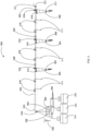
FIG. 1 shows an exemplary irrigation system for use with the present invention. -
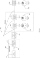
FIG. 2 shows a block diagram illustrating the exemplary processing architecture of a control device in according with a first preferred embodiment of the present invention. -
FIG. 3 shows a block diagram in accordance with further preferred embodiment of the present invention. -
FIG. 4A shows a block diagram in accordance with further preferred embodiment of the present invention. -
FIG. 4B shows a block diagram in accordance with an alternative preferred embodiment of the present invention. -
FIG. 5 shows a block diagram in accordance with further preferred embodiment of the present invention. -
FIG. 6 shows a block diagram in accordance with further preferred embodiment of the present invention. - For the purposes of promoting an understanding of the principles of the present invention, reference will now be made to the embodiments illustrated in the drawings and specific language will be used to describe the same. It will nevertheless be understood that no limitation of the scope of the present invention is hereby intended and such alterations and further modifications in the illustrated devices are contemplated as would normally occur to one skilled in the art.
- In accordance with the present invention, it should be understood that the term "drive unit" includes a number of sub-components including: a motor, a controller, a communication device (such as a PLC or the like) and a position sensor. Further, it should be understood that while the invention is discussed below with respect to three exemplary towers, the number of towers used may be expanded as needed without departing from the scope of the present invention.
- The terms "program," "computer program," "software application," "module," firmware" and the like as used herein, are defined as a sequence of instructions designed for execution on a computer system. The term "solid state" should be understood to refer to a range of solid state electronic devices which preferably include circuits or devices built from solid materials and in which the electrons, or other charge carriers, are confined entirely within the solid material. Exemplary solid-state components/materials may include crystalline, polycrystalline and amorphous solids, electrical conductors and semiconductors. Common solid-state devices may include transistors, microprocessor chips, and RAM.
- A program, computer program, module or software application may include a subroutine, a function, a procedure, an object implementation, an executable application, an applet, a servlet, a source code, an object code, a shared library, a dynamic load library and/or other sequence of instructions designed for execution on a computer system. A data storage means, as defined herein, includes many different types of computer readable media that allow a computer to read data therefrom and that maintain the data stored for the computer to be able to read the data again. Such data storage means can include, for example, nonvolatile memory, such as ROM, Flash memory, battery backed-up RAM, Disk drive memory, CD-ROM, DVD, and other permanent storage media. However, even volatile storage such a RAM, buffers, cache memory, and network circuits are contemplated to serve as such data storage means according to different embodiments of the present invention.
- Aspects of the systems and methods described herein may be implemented as functionality programmed into any of a variety of circuitry, including programmable logic devices (PLDs), such as field programmable gate arrays (FPGAs), programmable array logic (PAL) devices, electrically programmable logic and memory devices and standard cell-based devices, as well as application specific integrated circuits (ASICs). Some other possibilities for implementing aspects of the systems and methods includes: microcontrollers with memory, embedded microprocessors, firmware, software, etc. Furthermore, aspects of the systems and methods may be embodied in microprocessors having software -based circuit emulation, discrete logic (sequential and combinatorial), custom devices, fuzzy (neutral network) logic, quantum devices, and hybrids of any of the above device types. Of course, the underlying device technologies may be provided in a variety of component types, e.g., metal -oxide semiconductor field-effect transistor (MOSFET) technologies like complementary metal-oxide semiconductor (CMOS), bipolar technologies like emitter - coupled logic (ECL), polymer technologies (e.g., silicon-conjugated polymer and metal- conjugated polymer-metal structure), bidirectional triode thyristors (TRIAC), mixed analog and digital, and the like.
-
FIGS. 1-6 illustrate various configurations of irrigation systems which may be used with example implementations of the present invention. As should be understood, the irrigation systems shown inFIGS. 1-6 are exemplary systems onto which the features of the present invention may be integrated. Accordingly,FIGS. 1-6 are intended to be purely illustrative and any of a variety of systems (i.e. fixed systems as well as linear and center pivot self-propelled irrigation systems; stationary systems; corner systems) may be used with the present invention without limitation. For example, althoughFIG. 1 is shown as a center pivot irrigation system, theexemplary irrigation system 100 of the present invention may also be implemented as a linear irrigation system. Theexample irrigation system 100 is not intended to limit or define the scope of the present invention in any way. According to further preferred embodiments, the present invention may be used with a variety of motor types such as gas powered, DC powered, switch reluctance, single phase or poly phase AC, synchronous or asynchronous AC and the like. - With reference now to
FIG. 1 ,spans drive towers drive tower respective motors drive wheels FIG. 1 , theirrigation machine 100 may preferably further include an extension/overhang 121 which may include an endgun (not shown). - With reference now to
FIG. 2 , anexemplary control device 138 which represents functionality to control one or more operational aspects of theirrigation system 100 will now be discussed. As shown, anexemplary control device 138 preferably includes aprocessor 140, amemory 142, apositioning module 151, adata storage module 150 and anetwork interface 144. Theprocessor 140 provides processing functionality for thecontrol device 138 and may include any number of processors, micro-controllers, or other processing systems. Theprocessor 140 may execute one or more software programs that implement techniques described herein. Thememory 142 is an example of tangible computer-readable media that provides storage functionality to store various data associated with the operation of theprocessor 140 such as the software program and code segments mentioned above, or other data to instruct theprocessor 140 and other elements of thecontrol device 138 to perform the steps described herein. Thememory 142 may include, for example, removable and nonremovable memory elements such as RAM, ROM, Flash (e.g., SD Card, mini-SD card, micro-SD Card), magnetic, optical, USB memory devices, and so forth. Thenetwork interface 144 provides functionality to enable thecontrol device 138 to communicate with one ormore networks 149 through a variety of components such as wireless access points, transceivers and so forth, and any associated software employed by these components (e.g., drivers, configuration software, and so on). - In implementations,
exemplary control device 138 further includes apower control system 146 and a power-line BUS which include conductive transmission lines, circuits and the like for controlling and routing electric power, controlling its quality, and controlling the devices attached to a power-line carrier system as discussed further below. Further, the system of the present invention preferably may further include an irrigation position-determiningmodule 148 which may include a global positioning system (GPS) receiver (with or without real-time kinematic corrections/RTK) or the like to calculate a location of theirrigation system 100. Further, thecontrol device 138 is coupled to a guidance device orsimilar system 152 of the irrigation system 100 (e.g., steering assembly or steering mechanism) to control movement of theirrigation system 100. As shown, thecontrol device 138 further includes a positional -terrain compensation module 151 to assist in controlling the movement and locational awareness of the system. Further, thecontrol device 138 preferably further include multiple inputs and outputs to receive data from sensors 154 and monitoring devices as discussed further below. - With reference now to
FIG. 3 , anexemplary system 300 incorporating aspects of the present invention shall now be further discussed. As shown, thesystem 300 is attached to awater source 302 or the like to supply water or applicants under pressure to thesystem 300. Additionally, the system is preferably able to receive water or applicants under pressure from tanks orreservoirs exemplary irrigation system 300 includevalve assemblies emitters 313 and anend gun 321. Further the system as shown preferably includesexemplary transducers entire span 310. Further, thesystem 300 of the present invention further includes a control/pivot panel 402 as well as aflow meter 332 for monitoring overall water flow in the system. - Further the system includes solid
state tower boxes respective drive units respective drive units - Further, the
system 300 preferably includesGPS receivers 319 for receiving positional data. Still further, a system may include indirect crop sensors which preferably may include optional moisture sensors to determine the moisture levels in a given area of soil. Additionally, the sensors may further include optics to allow for the detection of crop type, stage of grown, health, presence of disease, rate of growth and the like. Still further, the system may includeground sensors 333 which may be wired to the control/pivot panel 402 or may wirelessly transmit ground sensor data to the system via a wireless receiver or the like as discussed below. - Still further, the control/
pivot panel 402 may further receive data from a connected or remote weather station or the like which is able to measure weather features such as humidity, wind speed, wind direction, pressure, precipitation, temperature and the like. Still further, the system may preferably further include a wired or wireless transceiver/router span 310 such as additional sensors and the like. - With reference now to
FIG. 4A , further aspects of the present invention shall now be further discussed. As shown inFIG. 4A , the power/control system of thepresent invention 400 includes the control/pivot panel 402 which provides control signals and power to a series of intermediate solid-state tower boxes tower box 408. As shown, the control/pivot panel 402 in accordance with a preferred embodiment of the present invention includes amain pivot controller 410 connected to a power-line carrier 414 which controls and directs power to downstream intermediate solid-state tower boxes LRDU tower box 408. Thepivot controller 410 is connected to the power-line carrier 414 via a serial communication connection 412 (i.e. RS-232) or the like. Thepivot panel 402 is connected to and provides power and control signals through the power-line carrier 414 to the downstream solid-state tower boxes line BUS 416 vialines 415. - According to further preferred embodiments, the control/
pivot panel 402 of the present invention is linked via thepower line BUS 416 andlines 415 to additional powered elements including: pump stations; injector pumps, valves, and other powered ancillary products. Further, the control/pivot panel 402 of the present invention may be remotely monitored and controlled by automated software programs via thepower line BUS 416 to operate (i.e. start, stop or change pressure, flow rate, valve position, etc.) aspects of the irrigation system utilizing a PLC control system from a master PLC in the control/pivot panel 402. This includes controlling pipeline valves (i.e.valves FIG. 3 ). Further, this may include controlling pumps (i.e. 335 inFIG. 3 ) which may include for example: electric engine powered pumps; chemigation injection pumps; biologies injection pumps; and the like. - According to a preferred embodiment, the power-
line BUS 416 provides 480 volts AC at 30 amps. According to alternative embodiments, the power-line BUS 416 may provide power anywhere between 120-480 volts at anywhere between 5-50 amps. For instance, the power-line BUS 416 may provide 120 volts AC at 5 amps. According to further preferred alternative embodiments, the power-line BUS 416 may alternatively provide and direct power having any of a variety of different voltages and amps as desired. According to a further preferred embodiment, the power-line carrier of present invention may preferably operate as a one or two-way system. - As further shown in
FIG. 4A , the power and control signals provided by the power-line BUS 416 (sent via lines 415) are first received by intermediate solid-state tower box 404 which receives, processes and thereafter directs the received power to acenter drive motor 418. Likewise, the power and control signals provided by the power-line box 416 are received by intermediate solid-state tower box 406 which receives, processes and thereafter directs the received power to centerdrive motor 420. Although not shown, any number of additional intermediate solid-state our boxes may further be incorporated as needed depending on the size of the irrigation system. Regardless of the number of intermediate solid-state our boxes, the power from the power-line bus 416 is finally received at a LRDU solid-state tower box 408 which likewise receives, processes and thereafter directs the received power to acenter drive motor 422. - As further shown in
FIG. 4B , according to an alternativepreferred embodiment 401, the system of the present alternatively utilizes a separate power circuit 417 (independent from the power-line BUS 416) for providing power from themain pivot controller 410. As shown inFIG. 4B , theseparate power circuit 417 provides power via a forward/re verse contactor 430 or from the irrigation machine's power source, directly tosolid state devices respective tower boxes power circuit 417 is an alternative power supply to thepower line BUS 416 or an additional/supplementary power supply to that in accordance with aspects of the present invention. - With reference now to
FIG. 5 , further detailed aspects of preferred embodiments of the present invention shall now be further discussed. As shown inFIG. 5 , an exemplary solid-state tower box 500 includessensors 502 which may include non-contact position sensors or GPS sensors. Alternatively, thesensors 502 include proportional or non- proportional (e.g. micro switch) sensors of any type. Still further, these sensors include contact sensors of any kind. As further shown, other sensors such astilt sensors 507 also provide sensor data through the internal power-line carrier 504. Further, data and control signals are directed through the power-line carrier 504 to and from a braking system such as aDC braking system 505 or the like. Additionally, data and control signals are directed through the power-line carrier 504 to and from drive systems and sensors such as solid- state motor contactor(s) 506 and the like. - As further shown, the exemplary solid-
state tower box 500 further include optionalconnected elements 510 which are provided via anIO expansion board 512 connected to a variety of sensor elements. As shown for example, theIO expansion board 512 is interconnected with a Tire Pressure Monitoring System (TPMS) 514, asoil monitoring sensor 516 and/orother sensor elements 518 including those discussed herein. As discussed above with respect toFIGS. 4A-B , the exemplary solid-state tower box 500 receives power and control signals provided by the main tower/pivot point power-line box 520 and receives, processes and thereafter directs the received power to centerdrive motor 508. As shown, the power/control signals are received through one or more branch circuit protection fuses 522. As further shown, the power from the main tower power-line 520 is additionally provided downstream to thenext tower box 524. - According to further preferred embodiments, data/signals received through the IO expansion board 512 (or from any other sensor input) is transmitted to the control/pivot panel 402 (as discussed above with regards to
FIGS. 2 and3 ). Thereafter, the data/signals are processed by algorithms in the control/pivot panel 402 to modify or create commands transmitted to the tower boxes via thepower line carrier 504. Alternatively, the sensor data is transmitted to a remote server via a cellular, radio or hard-wired data link for additional uses such as analytics, alerting remote operators and the like. In addition, GPS position data from each tower box is sent or made accessible to other tower boxes and/or thepivot controller 402. This data is then used for variety of purposes such as calculating alignment between spans. - With further reference now to
FIG. 6 , additional aspects of the present invention shall now be further discussed. As shown inFIG. 6 , an exemplary LRDU solid-state tower box 600 includes aGPS module 609, atilt sensor 611, an internal power-line carrier 602, and a solid-state motor contactor 604 (or the like). Additional alternative sensors are included as well, as discussed above. Further, data and control signals are directed through the power-line carrier 602 to and from a braking system such as aDC braking system 613 or the like, as well as to other motor controllers or sensors. Data from the LRDU solid-state tower box 600 is processed similar to the data from the intermediate drive towers as discussed above. - As further shown, the exemplary LRDU solid-
state tower box 600 further includes optionalconnected elements 610 which may be provided via anIO expansion board 612 connected to a variety of sensor elements. As shown, for example, theIO expansion board 612 is interconnected with a Tire Pressure Monitoring System (TPMS) 614, asoil monitoring sensor 616 and/orother sensor elements 618 including those discussed herein. As discussed above with respect toFIGS. 4A-B , the exemplary solid-state tower box 600 receives power and control signals provided by the main tower/pivot point power- line box via theprevious tower box 607 in the chain and receives, processes and thereafter directs the received power to centerdrive motor 605. As shown, the power/control signals are received through one or more branch circuit protection fuses 608. - While the above descriptions regarding the present invention contain much specificity, these should not be construed as limitations on the scope, but rather as examples. Many other variations are possible. For example, the processing elements of the present invention by the present invention may operate on a number of different frequencies, voltages, amps and BUS configurations. Further, the communications provided with the present invention may be designed to be duplex or simplex in nature. Further, as needs require, the processes for transmitting data to and from the present invention may be designed to be push or pull in nature. Still, further, each feature of the present invention may be made to be remotely activated and accessed from distant monitoring stations. Accordingly, data may preferably be uploaded to and downloaded from the present invention as needed.
- Accordingly, the scope of the present invention should be determined not by the embodiments illustrated, but by the appended claims and their legal equivalents.
Claims (16)
- A system (100) for providing power, control and communication within an irrigation system having a plurality of spans (102, 104, 106) and a drive system for moving the spans, wherein the system comprises:a plurality of sprinkler heads, wherein the plurality of sprinkler heads are configured to receive water under pressure and spray water onto a field to be irrigated;a position sensing system (148) ;a pivot panel (402), wherein the pivot panel (402) is comprised of a pivot panel processor (410), wherein the processor (410) is comprised of a power line control module for receiving and transmission of power and control signals to a plurality of solid state tower boxes (404, 406, 408);a power-line BUS (416); wherein the power-line BUS (416) is electrically connected to the pivot panel processor (410);a power-line carrier (415), wherein the power-line carrier (415) is comprised of a plurality of electrically conductive elements which are configured to connect and deliver signals to and from the power-line BUS (416) to the plurality of solid state tower boxes (404, 406, 408) ;a first drive tower (108), wherein the first drive tower (108) is comprised of a first tower box (404), a first tower drive unit (307), and a plurality of first tower drive wheels (115) wherein the first tower box (404) is electrically connected to a motor (418) of the first tower drive unit (307); wherein the first tower box (404) is configured to receive control signals and power directed from the power line control module; wherein the first tower drive unit (307) is configured to provide power to produce torque and braking on the first drive wheels (115);a second drive tower (109), wherein the second drive tower (109) is comprised of a second tower box (406), a second tower drive unit (309), and a plurality of second tower drive wheels (116); wherein the second tower box (406) is electrically connected to a motor (420) of the second tower drive unit (309); wherein the second tower box (406) is configured to receive control signals and power directed from the power line control module via the first drive tower (108); wherein the second tower drive unit (309) is configured to provide power to produce torque and braking on the second drive wheels (116); anda third drive tower (110), wherein the third drive tower (110) is comprised of a third tower box (408), a third tower drive unit (311), and a plurality of third tower drive wheels (118); wherein the third tower box (408) is electrically connected to a motor (422) of the third tower drive unit (311); wherein the third tower box (408) is configured to receive control signals and power directed from the power line control module via the second drive tower (406); wherein the third tower drive unit (311) is configured to provide power to produce torque and braking on the third drive wheels (118), the system being characterised in that each tower drive unit (307, 309, 311) further comprises a controller (506), a communication device and a position sensor (502) ; and in that each solid state tower box (404, 406, 408) is configured to receive, process and thereafter direct power to its respective motor (418, 420, 422), wherein data and the control signals are directed through the power-line carrier (115) to and from the braking system (505), and wherein data and the control signals are further directed through the power-line carrier (115) to and from the controller (506) and the position sensor (502) of the respective tower drive unit (307, 309, 311 .
- The system of claim 1, wherein the pivot panel (402) is connected to the power-line carrier via a serial communication connection.
- The system of claim 2, wherein the pivot controller is connected to the power-line carrier via a communication connection (412).
- The system of claim 2, wherein the power-line BUS is configured to provide 120-480 volts AC to the plurality of solid state tower boxes.
- The system of claim 4, wherein the power-line BUS transmits 480 volts AC at 30 amps.
- The system of claim 4, wherein the power-line BUS transmits 120 volts AC at 5 amps.
- The system of claim 3, wherein the system further comprises a second power circuit.
- The system of claim 7, wherein the second power circuit is independent from the power-line BUS.
- The system of claim 8, wherein the second power circuit is configured to transmit power from the main pivot controller to at least one tower box.
- The system of claim 4, wherein the system further comprises: a plurality of transducers (328, 330); wherein the transducers are configured to control and regulate water pressure.
- The system of claim 7, wherein the second power circuit transmits power via a forward/reverse contactor directly to solid state devices within at least one tower box.
- The system of claim 7, wherein the solid-state tower box is further comprised of an IO expansion board (512, 612); wherein the IO expansion board is connected to a plurality of sensor elements.
- The system of claim 12, wherein the solid-state tower box is further comprised of a non-contact position sensor (151).
- The system of claim 12, wherein the solid-state tower box is further comprised of a proportional sensor (502).
- The system of claim 12, wherein the solid-state tower box is further comprised of a Tire Pressure Monitoring System (TPMS) (514).
- The system of claim 12, wherein the power/control signals are received through one or more branch circuit protection fuses (522).
Applications Claiming Priority (2)
| Application Number | Priority Date | Filing Date | Title |
|---|---|---|---|
| US201762534822P | 2017-07-20 | 2017-07-20 | |
| PCT/US2018/042653 WO2019018506A1 (en) | 2017-07-20 | 2018-07-18 | System and method for solid state tower control |
Publications (4)
| Publication Number | Publication Date |
|---|---|
| EP3654760A1 EP3654760A1 (en) | 2020-05-27 |
| EP3654760A4 EP3654760A4 (en) | 2021-04-07 |
| EP3654760B1 true EP3654760B1 (en) | 2023-08-23 |
| EP3654760C0 EP3654760C0 (en) | 2023-08-23 |
Family
ID=65014052
Family Applications (1)
| Application Number | Title | Priority Date | Filing Date |
|---|---|---|---|
| EP18835101.9A Active EP3654760B1 (en) | 2017-07-20 | 2018-07-18 | System for solid state tower control of a center pivot irrigation system |
Country Status (7)
| Country | Link |
|---|---|
| US (1) | US10531616B2 (en) |
| EP (1) | EP3654760B1 (en) |
| CN (1) | CN110891414A (en) |
| AU (1) | AU2018304232B2 (en) |
| CA (1) | CA3068773A1 (en) |
| WO (1) | WO2019018506A1 (en) |
| ZA (1) | ZA202000009B (en) |
Families Citing this family (11)
| Publication number | Priority date | Publication date | Assignee | Title |
|---|---|---|---|---|
| WO2018222875A1 (en) | 2017-06-01 | 2018-12-06 | Valmont Industries, Inc. | System and method for irrigation management using machine learning workflows |
| US10862536B2 (en) * | 2018-08-28 | 2020-12-08 | Valmont Industries, Inc. | System and method for position correction using power line carrier communications |
| US10939627B2 (en) * | 2018-10-11 | 2021-03-09 | Valmont Industries, Inc. | System and method for cascading alignment of independent drive systems |
| US12439866B2 (en) | 2019-03-25 | 2025-10-14 | Realmfive, Inc. | Smart irrigation system |
| US12575515B2 (en) * | 2019-06-07 | 2026-03-17 | Valmont Industries, Inc. | System and method for the integrated use of predictive and machine learning analytics for a center pivot irrigation system |
| CN114126399B (en) | 2019-07-12 | 2023-10-03 | 瓦尔蒙特工业股份有限公司 | Systems and methods for detecting and eliminating flexural stress in irrigation machine jumpers |
| WO2021050341A1 (en) * | 2019-09-12 | 2021-03-18 | Valmont Industries, Inc. | System and method for analysis of current and voltage levels within a center pivot irrigation system |
| US11825778B1 (en) | 2020-05-05 | 2023-11-28 | Stephens Electric & Supply, Inc. | Direct pivot smart tower box module and communication system |
| US11382286B2 (en) * | 2020-05-07 | 2022-07-12 | Valmont Industries, Inc. | System, method and apparatus for irrigation control and data management |
| US11367344B2 (en) | 2020-11-13 | 2022-06-21 | Lindsay Corporation | System and method for managing data of an irrigation system |
| CN118055695A (en) * | 2021-10-06 | 2024-05-17 | 瓦尔蒙特工业股份有限公司 | Systems, methods and apparatus for filter and pendant clogging detection |
Family Cites Families (53)
| Publication number | Priority date | Publication date | Assignee | Title |
|---|---|---|---|---|
| US3823730A (en) | 1973-03-30 | 1974-07-16 | Integral Syst Inc | Alignment control system |
| US4138705A (en) | 1977-04-22 | 1979-02-06 | Lockwood Corporation | Over-power safety device for motor driven system |
| US4569481A (en) * | 1982-03-29 | 1986-02-11 | Reinke Manufacturing Co., Inc. | Corner watering system for center pivot irrigation machines |
| US4549694A (en) * | 1983-03-29 | 1985-10-29 | Davis John E | Corner watering system for center pivot irrigation machines |
| US4508269A (en) * | 1983-03-29 | 1985-04-02 | Reinke Manufacturing Co., Inc. | Corner watering system for center pivot irrigation machines |
| US4763836A (en) | 1983-09-30 | 1988-08-16 | Lyle William M | Irrigation system for precise water and chemical application |
| US4580731A (en) | 1984-03-30 | 1986-04-08 | Desert Rain Irrigation Co. | Center pivot irrigation system control |
| US4693425A (en) * | 1984-06-29 | 1987-09-15 | Lindsay Manufacturing Co. | Drive for movable irrigation system and the like |
| US4626984A (en) | 1984-08-29 | 1986-12-02 | Valmont Industries, Inc. | Remote computer control for irrigation systems |
| US5246164A (en) * | 1991-12-16 | 1993-09-21 | Mccann Ian R | Method and apparatus for variable application of irrigation water and chemicals |
| AU2267997A (en) | 1996-02-12 | 1997-08-28 | Powerhouse Corporation | Irrigation control system |
| US5884224A (en) * | 1997-03-07 | 1999-03-16 | J.R. Simplot Company | Mobile mounted remote sensing/application apparatus for interacting with selected areas of interest within a field |
| US5927603A (en) * | 1997-09-30 | 1999-07-27 | J. R. Simplot Company | Closed loop control system, sensing apparatus and fluid application system for a precision irrigation device |
| US20020100814A1 (en) * | 2001-01-31 | 2002-08-01 | Ron Pollak | Method and means for controlling the functions of an irrigation system and ancillary equipment |
| US20020107582A1 (en) * | 2001-02-07 | 2002-08-08 | Ron Pollak | Local area network for distributing controls to peripheral controllers on mechanized irrigation equipment |
| US6755362B2 (en) | 2001-10-04 | 2004-06-29 | Neal Krieger | Irrigation system with variable speed drive system |
| US7584053B2 (en) | 2004-08-05 | 2009-09-01 | Reintech, Llc | Universal remote terminal unit and method for tracking the position of self-propelled irrigation systems |
| US20070001035A1 (en) | 2005-06-29 | 2007-01-04 | Reinke Manufacturing Company, Inc. | GPS guidance system for linear move irrigation apparatus |
| JP4776435B2 (en) | 2006-05-24 | 2011-09-21 | 本田技研工業株式会社 | Travel drive mechanism of self-propelled work machine |
| US20080157995A1 (en) * | 2006-12-29 | 2008-07-03 | Rain Bird Corporation | Irrigation two-wire communication control |
| US20090166451A1 (en) | 2007-12-27 | 2009-07-02 | Lindsay Corporation | Wind-Powered Irrigation Machine |
| NZ568218A (en) | 2008-05-12 | 2010-11-26 | Wmc Technology Ltd | An irrigator control system that uses irrigator position, water source information, and field information to control moving irrigators |
| US8777133B2 (en) | 2009-12-01 | 2014-07-15 | Lindsay Corporation | Irrigation system for small fields |
| US8829736B2 (en) | 2010-06-09 | 2014-09-09 | Lindsay Corporation | Low-power start-up and direction control circuitry for an irrigation system |
| CN201766916U (en) * | 2010-07-16 | 2011-03-23 | 山东华泰保尔水务农业装备工程有限公司 | Electric round sprinkler |
| CN103153041B (en) * | 2010-08-11 | 2016-01-13 | 瓦尔蒙工业公司 | For the water distribution assembly of mechanization irrigation system automatically promoted |
| US9022305B2 (en) | 2010-08-30 | 2015-05-05 | Valmont Industries, Inc. | Self-propelled mechanized irrigation system with a tire pressure monitoring system |
| US20130008977A1 (en) | 2011-07-05 | 2013-01-10 | Lindsay Corporation | System and method for controlling operation of an irrigation system end gun |
| US8849467B2 (en) | 2011-07-13 | 2014-09-30 | Lindsay Corporation | Control system for stopping or reversing movement of an irrigation system |
| US8948979B2 (en) * | 2011-07-14 | 2015-02-03 | Valmont Industries, Inc. | Variable-speed irrigation system |
| US8763937B2 (en) | 2011-08-29 | 2014-07-01 | Lindsay Corporation | Methods and systems for aligning irrigation systems |
| US8876026B2 (en) | 2011-10-06 | 2014-11-04 | Lindsay Corporation | Method and system for orienting solar powered irrigation systems |
| US20130090772A1 (en) * | 2011-10-06 | 2013-04-11 | Lindsay Corporation | Method and system for orienting an irrigation system to minimize wind damage |
| US8936208B2 (en) | 2011-10-07 | 2015-01-20 | Lindsay Corporation | Method and system for operating irrigation systems motors |
| US20130253752A1 (en) * | 2012-03-23 | 2013-09-26 | Lindsay Corporation | Continuous-move irrigation control system |
| US9459628B1 (en) | 2012-08-06 | 2016-10-04 | Precision Circle, LLC | System and method for moving spans of an irrigation system |
| US20140225747A1 (en) * | 2013-02-08 | 2014-08-14 | Karlyle Haaland | Wireless waterline pressure sensor system for self-propelled irrigation systems |
| AU2014259718A1 (en) | 2013-05-02 | 2015-11-12 | Valmont Industries, Inc. | Variable-speed irrigation system having an extension arm |
| US20140371971A1 (en) | 2013-06-18 | 2014-12-18 | Lindsay Corporation | Single wheel irrigation tower |
| US20150053786A1 (en) | 2013-08-21 | 2015-02-26 | Trimble Navigation Limited | Intelligent precision irrigation system |
| CN203523468U (en) * | 2013-08-23 | 2014-04-09 | 高平 | Electric horizontal-moving and center-pivot multifunctional irrigating machine provided with rotary cantilever |
| US20150060580A1 (en) * | 2013-08-29 | 2015-03-05 | Lindsay Corporation | Solid-state span alignment and pivot positioning |
| CN103782875A (en) * | 2014-01-23 | 2014-05-14 | 北京东方润泽生态科技股份有限公司 | Novel irrigation system |
| CN103891581A (en) | 2014-04-16 | 2014-07-02 | 安徽艾瑞德农业装备发展有限公司 | Power line carrier remote control system of large electric sprinkling machine |
| JP5860093B2 (en) | 2014-04-30 | 2016-02-16 | ファナック株式会社 | Brake drive control device with abnormality detection function |
| US9661808B2 (en) | 2014-06-06 | 2017-05-30 | Irrovation LLC | Irrigation system with dual-controller drive assemblies |
| WO2015191556A2 (en) | 2014-06-10 | 2015-12-17 | Agbotic, Inc. | Robotic gantry bridge for farming |
| CN104082107A (en) * | 2014-07-16 | 2014-10-08 | 苏州经贸职业技术学院 | Intelligent irrigation system |
| US10021841B2 (en) | 2015-08-28 | 2018-07-17 | Lindsay Corporation | Local and integrated remote control system and method for retrofitting existing electric center irrigation pivots |
| RU172353U1 (en) * | 2016-10-17 | 2017-07-05 | Общество С Ограниченной Ответственностью "Экосфера" | CIRCULATING RAINING MACHINE |
| US20180310496A1 (en) | 2017-04-26 | 2018-11-01 | Lindsay Corporation | System for managing speed commands for motor-driven irrigation system |
| WO2018222875A1 (en) * | 2017-06-01 | 2018-12-06 | Valmont Industries, Inc. | System and method for irrigation management using machine learning workflows |
| US10440905B2 (en) * | 2017-10-05 | 2019-10-15 | Valmont Industries, Inc. | System and method for irrigation management using VRI ray casting algorithms within irrigation machine workflows |
-
2018
- 2018-07-18 WO PCT/US2018/042653 patent/WO2019018506A1/en not_active Ceased
- 2018-07-18 US US16/038,859 patent/US10531616B2/en active Active
- 2018-07-18 EP EP18835101.9A patent/EP3654760B1/en active Active
- 2018-07-18 CN CN201880047115.2A patent/CN110891414A/en active Pending
- 2018-07-18 CA CA3068773A patent/CA3068773A1/en active Pending
- 2018-07-18 AU AU2018304232A patent/AU2018304232B2/en active Active
-
2020
- 2020-01-02 ZA ZA2020/00009A patent/ZA202000009B/en unknown
Also Published As
| Publication number | Publication date |
|---|---|
| BR112020001023A2 (en) | 2020-07-14 |
| AU2018304232B2 (en) | 2024-09-19 |
| ZA202000009B (en) | 2020-12-23 |
| CN110891414A (en) | 2020-03-17 |
| NZ760644A (en) | 2025-05-02 |
| CA3068773A1 (en) | 2019-01-24 |
| EP3654760A4 (en) | 2021-04-07 |
| US10531616B2 (en) | 2020-01-14 |
| AU2018304232A1 (en) | 2020-01-30 |
| EP3654760A1 (en) | 2020-05-27 |
| US20190021245A1 (en) | 2019-01-24 |
| WO2019018506A1 (en) | 2019-01-24 |
| EP3654760C0 (en) | 2023-08-23 |
Similar Documents
| Publication | Publication Date | Title |
|---|---|---|
| US10531616B2 (en) | System and method for solid state tower control | |
| AU2019213837B2 (en) | System and method for GPS alignment using real-time kinetics | |
| AU2018309604B2 (en) | System and method for variable rate irrigation wind control and compensation | |
| US12389842B2 (en) | System and method for detecting end gun status | |
| CA3142512C (en) | System and method for detecting and removing deflection stresses from irrigation machine spans | |
| EP3863769B1 (en) | Method for cascading alignment of independent drive systems | |
| US10862536B2 (en) | System and method for position correction using power line carrier communications | |
| CA3108011C (en) | System and method for position correction using power line carrier communications | |
| BR112020001023B1 (en) | SYSTEM FOR PROVIDING POWER, CONTROL AND COMMUNICATION WITHIN AN IRRIGATION SYSTEM WITH A PLURALITY OF FLEEDS AND A DRIVE SYSTEM TO MOVE THE FLIGHTS |
Legal Events
| Date | Code | Title | Description |
|---|---|---|---|
| STAA | Information on the status of an ep patent application or granted ep patent |
Free format text: STATUS: THE INTERNATIONAL PUBLICATION HAS BEEN MADE |
|
| PUAI | Public reference made under article 153(3) epc to a published international application that has entered the european phase |
Free format text: ORIGINAL CODE: 0009012 |
|
| STAA | Information on the status of an ep patent application or granted ep patent |
Free format text: STATUS: REQUEST FOR EXAMINATION WAS MADE |
|
| 17P | Request for examination filed |
Effective date: 20200120 |
|
| AK | Designated contracting states |
Kind code of ref document: A1 Designated state(s): AL AT BE BG CH CY CZ DE DK EE ES FI FR GB GR HR HU IE IS IT LI LT LU LV MC MK MT NL NO PL PT RO RS SE SI SK SM TR |
|
| AX | Request for extension of the european patent |
Extension state: BA ME |
|
| DAV | Request for validation of the european patent (deleted) | ||
| DAX | Request for extension of the european patent (deleted) | ||
| A4 | Supplementary search report drawn up and despatched |
Effective date: 20210311 |
|
| RIC1 | Information provided on ipc code assigned before grant |
Ipc: G05D 7/00 20060101ALI20210304BHEP Ipc: H04B 3/54 20060101ALI20210304BHEP Ipc: A01G 25/16 20060101ALI20210304BHEP Ipc: A01G 25/00 20060101AFI20210304BHEP Ipc: A01G 25/09 20060101ALI20210304BHEP Ipc: G05D 7/06 20060101ALI20210304BHEP Ipc: G05B 19/042 20060101ALI20210304BHEP |
|
| STAA | Information on the status of an ep patent application or granted ep patent |
Free format text: STATUS: EXAMINATION IS IN PROGRESS |
|
| 17Q | First examination report despatched |
Effective date: 20211103 |
|
| GRAP | Despatch of communication of intention to grant a patent |
Free format text: ORIGINAL CODE: EPIDOSNIGR1 |
|
| STAA | Information on the status of an ep patent application or granted ep patent |
Free format text: STATUS: GRANT OF PATENT IS INTENDED |
|
| RIC1 | Information provided on ipc code assigned before grant |
Ipc: H04B 3/60 20060101ALI20230130BHEP Ipc: G05B 19/042 20060101ALI20230130BHEP Ipc: H04B 3/54 20060101ALI20230130BHEP Ipc: G05D 7/06 20060101ALI20230130BHEP Ipc: G05D 7/00 20060101ALI20230130BHEP Ipc: A01G 25/16 20060101ALI20230130BHEP Ipc: A01G 25/09 20060101ALI20230130BHEP Ipc: A01G 25/00 20060101AFI20230130BHEP |
|
| INTG | Intention to grant announced |
Effective date: 20230302 |
|
| GRAS | Grant fee paid |
Free format text: ORIGINAL CODE: EPIDOSNIGR3 |
|
| GRAA | (expected) grant |
Free format text: ORIGINAL CODE: 0009210 |
|
| STAA | Information on the status of an ep patent application or granted ep patent |
Free format text: STATUS: THE PATENT HAS BEEN GRANTED |
|
| AK | Designated contracting states |
Kind code of ref document: B1 Designated state(s): AL AT BE BG CH CY CZ DE DK EE ES FI FR GB GR HR HU IE IS IT LI LT LU LV MC MK MT NL NO PL PT RO RS SE SI SK SM TR |
|
| REG | Reference to a national code |
Ref country code: GB Ref legal event code: FG4D |
|
| REG | Reference to a national code |
Ref country code: CH Ref legal event code: EP |
|
| REG | Reference to a national code |
Ref country code: DE Ref legal event code: R096 Ref document number: 602018056089 Country of ref document: DE |
|
| REG | Reference to a national code |
Ref country code: IE Ref legal event code: FG4D |
|
| U01 | Request for unitary effect filed |
Effective date: 20230920 |
|
| U07 | Unitary effect registered |
Designated state(s): AT BE BG DE DK EE FI FR IT LT LU LV MT NL PT SE SI Effective date: 20230926 |
|
| PG25 | Lapsed in a contracting state [announced via postgrant information from national office to epo] |
Ref country code: GR Free format text: LAPSE BECAUSE OF FAILURE TO SUBMIT A TRANSLATION OF THE DESCRIPTION OR TO PAY THE FEE WITHIN THE PRESCRIBED TIME-LIMIT Effective date: 20231124 |
|
| PG25 | Lapsed in a contracting state [announced via postgrant information from national office to epo] |
Ref country code: IS Free format text: LAPSE BECAUSE OF FAILURE TO SUBMIT A TRANSLATION OF THE DESCRIPTION OR TO PAY THE FEE WITHIN THE PRESCRIBED TIME-LIMIT Effective date: 20231223 |
|
| PG25 | Lapsed in a contracting state [announced via postgrant information from national office to epo] |
Ref country code: RS Free format text: LAPSE BECAUSE OF FAILURE TO SUBMIT A TRANSLATION OF THE DESCRIPTION OR TO PAY THE FEE WITHIN THE PRESCRIBED TIME-LIMIT Effective date: 20230823 Ref country code: NO Free format text: LAPSE BECAUSE OF FAILURE TO SUBMIT A TRANSLATION OF THE DESCRIPTION OR TO PAY THE FEE WITHIN THE PRESCRIBED TIME-LIMIT Effective date: 20231123 Ref country code: IS Free format text: LAPSE BECAUSE OF FAILURE TO SUBMIT A TRANSLATION OF THE DESCRIPTION OR TO PAY THE FEE WITHIN THE PRESCRIBED TIME-LIMIT Effective date: 20231223 Ref country code: HR Free format text: LAPSE BECAUSE OF FAILURE TO SUBMIT A TRANSLATION OF THE DESCRIPTION OR TO PAY THE FEE WITHIN THE PRESCRIBED TIME-LIMIT Effective date: 20230823 Ref country code: GR Free format text: LAPSE BECAUSE OF FAILURE TO SUBMIT A TRANSLATION OF THE DESCRIPTION OR TO PAY THE FEE WITHIN THE PRESCRIBED TIME-LIMIT Effective date: 20231124 |
|
| PG25 | Lapsed in a contracting state [announced via postgrant information from national office to epo] |
Ref country code: PL Free format text: LAPSE BECAUSE OF FAILURE TO SUBMIT A TRANSLATION OF THE DESCRIPTION OR TO PAY THE FEE WITHIN THE PRESCRIBED TIME-LIMIT Effective date: 20230823 |
|
| PG25 | Lapsed in a contracting state [announced via postgrant information from national office to epo] |
Ref country code: ES Free format text: LAPSE BECAUSE OF FAILURE TO SUBMIT A TRANSLATION OF THE DESCRIPTION OR TO PAY THE FEE WITHIN THE PRESCRIBED TIME-LIMIT Effective date: 20230823 |
|
| PG25 | Lapsed in a contracting state [announced via postgrant information from national office to epo] |
Ref country code: SM Free format text: LAPSE BECAUSE OF FAILURE TO SUBMIT A TRANSLATION OF THE DESCRIPTION OR TO PAY THE FEE WITHIN THE PRESCRIBED TIME-LIMIT Effective date: 20230823 Ref country code: RO Free format text: LAPSE BECAUSE OF FAILURE TO SUBMIT A TRANSLATION OF THE DESCRIPTION OR TO PAY THE FEE WITHIN THE PRESCRIBED TIME-LIMIT Effective date: 20230823 Ref country code: ES Free format text: LAPSE BECAUSE OF FAILURE TO SUBMIT A TRANSLATION OF THE DESCRIPTION OR TO PAY THE FEE WITHIN THE PRESCRIBED TIME-LIMIT Effective date: 20230823 Ref country code: CZ Free format text: LAPSE BECAUSE OF FAILURE TO SUBMIT A TRANSLATION OF THE DESCRIPTION OR TO PAY THE FEE WITHIN THE PRESCRIBED TIME-LIMIT Effective date: 20230823 Ref country code: SK Free format text: LAPSE BECAUSE OF FAILURE TO SUBMIT A TRANSLATION OF THE DESCRIPTION OR TO PAY THE FEE WITHIN THE PRESCRIBED TIME-LIMIT Effective date: 20230823 |
|
| REG | Reference to a national code |
Ref country code: DE Ref legal event code: R097 Ref document number: 602018056089 Country of ref document: DE |
|
| PLBE | No opposition filed within time limit |
Free format text: ORIGINAL CODE: 0009261 |
|
| STAA | Information on the status of an ep patent application or granted ep patent |
Free format text: STATUS: NO OPPOSITION FILED WITHIN TIME LIMIT |
|
| 26N | No opposition filed |
Effective date: 20240524 |
|
| U20 | Renewal fee for the european patent with unitary effect paid |
Year of fee payment: 7 Effective date: 20240729 |
|
| PG25 | Lapsed in a contracting state [announced via postgrant information from national office to epo] |
Ref country code: MC Free format text: LAPSE BECAUSE OF FAILURE TO SUBMIT A TRANSLATION OF THE DESCRIPTION OR TO PAY THE FEE WITHIN THE PRESCRIBED TIME-LIMIT Effective date: 20230823 |
|
| REG | Reference to a national code |
Ref country code: CH Ref legal event code: PL |
|
| GBPC | Gb: european patent ceased through non-payment of renewal fee |
Effective date: 20240718 |
|
| PG25 | Lapsed in a contracting state [announced via postgrant information from national office to epo] |
Ref country code: CH Free format text: LAPSE BECAUSE OF NON-PAYMENT OF DUE FEES Effective date: 20240731 |
|
| PG25 | Lapsed in a contracting state [announced via postgrant information from national office to epo] |
Ref country code: GB Free format text: LAPSE BECAUSE OF NON-PAYMENT OF DUE FEES Effective date: 20240718 |
|
| PG25 | Lapsed in a contracting state [announced via postgrant information from national office to epo] |
Ref country code: IE Free format text: LAPSE BECAUSE OF NON-PAYMENT OF DUE FEES Effective date: 20240718 |
|
| U20 | Renewal fee for the european patent with unitary effect paid |
Year of fee payment: 8 Effective date: 20250728 |
|
| PG25 | Lapsed in a contracting state [announced via postgrant information from national office to epo] |
Ref country code: CY Free format text: LAPSE BECAUSE OF FAILURE TO SUBMIT A TRANSLATION OF THE DESCRIPTION OR TO PAY THE FEE WITHIN THE PRESCRIBED TIME-LIMIT; INVALID AB INITIO Effective date: 20180718 |
|
| PG25 | Lapsed in a contracting state [announced via postgrant information from national office to epo] |
Ref country code: HU Free format text: LAPSE BECAUSE OF FAILURE TO SUBMIT A TRANSLATION OF THE DESCRIPTION OR TO PAY THE FEE WITHIN THE PRESCRIBED TIME-LIMIT; INVALID AB INITIO Effective date: 20180718 |