EP3654682A1 - Method and apparatus for frequency spectrum system security - Google Patents
Method and apparatus for frequency spectrum system security Download PDFInfo
- Publication number
- EP3654682A1 EP3654682A1 EP19204627.4A EP19204627A EP3654682A1 EP 3654682 A1 EP3654682 A1 EP 3654682A1 EP 19204627 A EP19204627 A EP 19204627A EP 3654682 A1 EP3654682 A1 EP 3654682A1
- Authority
- EP
- European Patent Office
- Prior art keywords
- optical
- transmitter
- communications signal
- frequency
- signal
- Prior art date
- Legal status (The legal status is an assumption and is not a legal conclusion. Google has not performed a legal analysis and makes no representation as to the accuracy of the status listed.)
- Granted
Links
Images

Classifications
-
- H—ELECTRICITY
- H04—ELECTRIC COMMUNICATION TECHNIQUE
- H04L—TRANSMISSION OF DIGITAL INFORMATION, e.g. TELEGRAPHIC COMMUNICATION
- H04L63/00—Network architectures or network communication protocols for network security
- H04L63/14—Network architectures or network communication protocols for network security for detecting or protecting against malicious traffic
- H04L63/1441—Countermeasures against malicious traffic
- H04L63/1466—Active attacks involving interception, injection, modification, spoofing of data unit addresses, e.g. hijacking, packet injection or TCP sequence number attacks
-
- H—ELECTRICITY
- H04—ELECTRIC COMMUNICATION TECHNIQUE
- H04B—TRANSMISSION
- H04B10/00—Transmission systems employing electromagnetic waves other than radio-waves, e.g. infrared, visible or ultraviolet light, or employing corpuscular radiation, e.g. quantum communication
- H04B10/07—Arrangements for monitoring or testing transmission systems; Arrangements for fault measurement of transmission systems
- H04B10/075—Arrangements for monitoring or testing transmission systems; Arrangements for fault measurement of transmission systems using an in-service signal
- H04B10/079—Arrangements for monitoring or testing transmission systems; Arrangements for fault measurement of transmission systems using an in-service signal using measurements of the data signal
- H04B10/0795—Performance monitoring; Measurement of transmission parameters
- H04B10/07957—Monitoring or measuring wavelength
-
- H—ELECTRICITY
- H04—ELECTRIC COMMUNICATION TECHNIQUE
- H04B—TRANSMISSION
- H04B10/00—Transmission systems employing electromagnetic waves other than radio-waves, e.g. infrared, visible or ultraviolet light, or employing corpuscular radiation, e.g. quantum communication
- H04B10/50—Transmitters
- H04B10/516—Details of coding or modulation
- H04B10/5161—Combination of different modulation schemes
-
- H—ELECTRICITY
- H04—ELECTRIC COMMUNICATION TECHNIQUE
- H04L—TRANSMISSION OF DIGITAL INFORMATION, e.g. TELEGRAPHIC COMMUNICATION
- H04L63/00—Network architectures or network communication protocols for network security
- H04L63/12—Applying verification of the received information
- H04L63/126—Applying verification of the received information the source of the received data
-
- H—ELECTRICITY
- H04—ELECTRIC COMMUNICATION TECHNIQUE
- H04W—WIRELESS COMMUNICATION NETWORKS
- H04W12/00—Security arrangements; Authentication; Protecting privacy or anonymity
- H04W12/10—Integrity
- H04W12/108—Source integrity
-
- H—ELECTRICITY
- H04—ELECTRIC COMMUNICATION TECHNIQUE
- H04W—WIRELESS COMMUNICATION NETWORKS
- H04W12/00—Security arrangements; Authentication; Protecting privacy or anonymity
- H04W12/12—Detection or prevention of fraud
- H04W12/121—Wireless intrusion detection systems [WIDS]; Wireless intrusion prevention systems [WIPS]
- H04W12/122—Counter-measures against attacks; Protection against rogue devices
-
- H—ELECTRICITY
- H04—ELECTRIC COMMUNICATION TECHNIQUE
- H04B—TRANSMISSION
- H04B10/00—Transmission systems employing electromagnetic waves other than radio-waves, e.g. infrared, visible or ultraviolet light, or employing corpuscular radiation, e.g. quantum communication
- H04B10/80—Optical aspects relating to the use of optical transmission for specific applications, not provided for in groups H04B10/03 - H04B10/70, e.g. optical power feeding or optical transmission through water
- H04B10/85—Protection from unauthorised access, e.g. eavesdrop protection
-
- H—ELECTRICITY
- H04—ELECTRIC COMMUNICATION TECHNIQUE
- H04B—TRANSMISSION
- H04B2210/00—Indexing scheme relating to optical transmission systems
- H04B2210/006—Devices for generating or processing an RF signal by optical means
-
- H—ELECTRICITY
- H04—ELECTRIC COMMUNICATION TECHNIQUE
- H04W—WIRELESS COMMUNICATION NETWORKS
- H04W4/00—Services specially adapted for wireless communication networks; Facilities therefor
- H04W4/30—Services specially adapted for particular environments, situations or purposes
- H04W4/40—Services specially adapted for particular environments, situations or purposes for vehicles, e.g. vehicle-to-pedestrians [V2P]
-
- H—ELECTRICITY
- H04—ELECTRIC COMMUNICATION TECHNIQUE
- H04W—WIRELESS COMMUNICATION NETWORKS
- H04W4/00—Services specially adapted for wireless communication networks; Facilities therefor
- H04W4/70—Services for machine-to-machine communication [M2M] or machine type communication [MTC]
Definitions
- the disclosure relates to optical systems and security features for frequency-based communications systems.
- Embedded electrical and computing systems are used in many applications, including manned and unmanned vehicle control systems, as well as other types of control systems. For instance, flight control systems, engine control systems, generator control systems, and the like, are examples of embedded electrical and computing systems. These types of embedded systems may be exposed, during regular operational use, to a variety of different types of hostile cyberattacks. For example, an unauthorized user may try to circumvent access controls to take command of an engine control system of an aircraft, e.g., to induce damage to the engine, or worse, crash the aircraft.
- the disclosure is directed to a method including: receiving, by a receiver, from a transmitter, a communications signal; determining, by processing circuitry, at least one frequency characteristic of the communications signal; and determining, by the processing circuitry, whether the transmitter is a verified transmitter based on the at least one frequency characteristic and at least one verified frequency characteristic stored by a memory associated with the processing circuitry.
- the receiver may detect data originating from devices other than the transmitter. This may increase security of a system and reduce a likelihood of successful attacks on the system using man-in-the-middle attacks or replacement of the transmitter.
- the receiver includes an optical receiver
- the transmitter includes an optical transmitter
- the communications signal includes an optical signal
- the optical signal encodes data
- the at least one frequency characteristic includes an actual carrier frequency of the communications signal.
- the actual carrier frequency of the communications signal emitted by the transmitter may be different from a nominal carrier frequency and may be unique to the transmitter when determined to a sufficient level of precision.
- the at least one frequency characteristic includes a phase modulation sideband frequency of the communications signal.
- the phase modulation sideband frequency of the communications signal may be unique to the transmitter when determined to a sufficient level of precision.
- the at least one frequency characteristic includes an amplitude of the optical signal at an actual carrier frequency of the communications signal.
- the at least one frequency characteristic includes an amplitude of the communications signal at a phase modulation sideband frequency.
- the communications signal is a first communications signal.
- the method further includes receiving a second communications signal. Determining the at least one frequency characteristic includes determining a frequency of constructive interference between the first communications signal and the second communications signal.
- the method further includes outputting, by the processing circuitry, an indication of the whether the transmitter is a verified transmitter.
- the method further includes, in response to determining that the transmitter is not a verified transmitter, discarding data encoded in the communications signal.
- the method further includes, in response to determining that the transmitter is a verified transmitter, decoding data encoded in the communications signal.
- the disclosure is directed to a system including: a receiver configured to receive a communications signal from a transmitter; and processing circuitry configured to: determine at least one frequency characteristic of the communications signal; and determine whether the transmitter is a verified transmitter based on the at least one frequency characteristic and at least one verified frequency characteristic stored by a memory associated with the processing circuitry.
- the receiver and the processing circuitry may verify integrity of the communications link between the transmitter and receiver, reducing a likelihood of success of intrusion in the system by attackers. This may be particularly applicable to embedded electrical and computing systems, such as those used in flight control systems, engine control systems, generator control systems, and the like.
- the receiver includes an optical receiver
- the transmitter includes an optical transmitter
- the communications signal includes an optical signal
- the optical signal encodes data
- the at least one frequency characteristic includes an actual carrier frequency of the communications signal.
- the at least one frequency characteristic includes a phase modulation sideband frequency of the communications signal.
- the at least one frequency characteristic includes an amplitude of the communications signal at an actual carrier frequency of the communications signal.
- the at least one frequency characteristic includes an amplitude of the communications signal at a phase modulation sideband frequency.
- the communications signal is a first communications signal.
- the processing circuitry is configured to determine the at least one frequency characteristic by determining a frequency of constructive interference between the first communications signal and a second communications signal.
- the processing circuitry is further configured to output an indication of the whether the transmitter is a verified transmitter.
- the processing circuitry is further configured to, in response to determining that the transmitter is not a verified transmitter, discard data encoded in the communications signal.
- the processing circuitry is further configured to, in response to determining that the transmitter is a verified transmitter, decode data encoded in the communications signal.
- the disclosure describes frequency spectrum-based communications systems including a receiver and a transmitter that are keyed to each other using information based on at least one frequency characteristic of the transmitter.
- the frequency spectrum-based communications system may be an optical communications system.
- the frequency spectrum-based communications system may be a radio frequency (RF) communications system.
- the transmitter outputs a communications signal, such as a pulse train, to transmit data from the transmitter to the receiver.
- the transmitter outputs the communications signal as electromagnetic energy with a predetermined frequency spectrum. While the transmitter may be associated with a nominal carrier frequency, the actual communications signal emitted by the transmitter may be unique to the specific transmitter when analyzed with sufficient precision.
- the actual carrier frequency of the communications signal emitted by the transmitter may be different from the nominal carrier frequency and unique to the transmitter when determined to a sufficient level of precision.
- the frequency of a phase modulation sideband may be unique to the transmitter when determined to a sufficient level of precision.
- a security key may be generated.
- the security key may be stored in a memory associated with a corresponding receiver to which the transmitter is communicatively coupled, e.g., during manufacture or installation of the communication system.
- the security key (the at least one frequency characteristic of the optical transmitter) may identify a verified transmitter.
- processing circuitry associated with the receiver may determine at least one frequency characteristic of a received communications signal.
- the processing circuitry may determine whether the received communications signal was output by the verified transmitter based on the at least one frequency characteristic of the received communications signal and the stored at least one frequency characteristic associated with the verified transmitter determine whether the received communications signal was output by the verified transmitter.
- the receiver and associated processing circuitry may verify integrity of the communications link between the transmitter and receiver, reducing a likelihood of success of intrusion in the system by attackers.
- This may be particularly applicable to embedded electrical and computing systems, such as those used in flight control systems, engine control systems, generator control systems, and the like.
- the transmitter and receiver are an optical transmitter and an optical receiver
- the communication coupling between the transmitter and receiver is an optical connection, such as a fiber optic cable.
- the systems and techniques described herein may be applied to other frequency-based communications systems, such as, for example RF communication systems.
- FIG. 1 is a conceptual diagram illustrating an example gas turbine engine 20 that includes an optical system 22, in accordance with one or more aspects of the present disclosure.
- Gas turbine engine 20 is a primary propulsion engine that provides thrust for flight operations of a vehicle, such as an aircraft, marine craft, or the like.
- gas turbine engine 20 is a two-spool engine having a high pressure (HP) spool 24 and a low pressure (LP) spool 26.
- HP high pressure
- LP low pressure
- gas turbine engine 20 may include three or more spools, e.g., may include an intermediate pressure (IP) spool and/or other spools.
- IP intermediate pressure
- gas turbine engine 20 is a turbofan engine, wherein LP spool 26 is operative to drive a propulsor in the form of a turbofan (fan) system 28. In other examples, gas turbine engine 20 may not include a LP spool or fan system 28. In some examples, gas turbine engine 20 may include any suitable turbine powered-engine propulsion system, including but not limited to, a turbojet engine or a turboprop engine.
- Gas turbine engine 20 includes a fan system 28 in fluid communication with a bypass duct 30 and a compressor system 32.
- a diffuser 34 is in fluid communication with compressor system 32.
- a combustion system 36 is fluidically disposed between compressor system 32 and a high pressure (HP) turbine system 38 (e.g., disposed between compressor system 32 and HP turbine system 38 such that air or another fluid may flow from compressor system 32 to combustion system 36 to HP turbine system 38).
- HP high pressure
- combustion system 36 includes a combustion liner (not shown) that encloses a continuous combustion process.
- combustion system 36 may take other forms, and may be, for example, a wave rotor combustion system, a rotary valve combustion system, a pulse detonation combustion system, or a slinger combustion system, and may employ deflagration and/or detonation combustion processes.
- a low pressure (LP) turbine system 40 is fluidically disposed between HP turbine system 38 and a nozzle 42A configured to discharge a core flow of gas turbine engine 20 (e.g., disposed between HP turbine system 38 and nozzle 42A such that air or another fluid may flow from HP turbine system 38 to LP turbine system 40 to nozzle 42A).
- a nozzle 42B is in fluid communication with bypass duct 30, and operative to transmit a bypass flow generated by fan system 28 around the core of gas turbine engine 20.
- other nozzle arrangements may be used, e.g., a common nozzle for core and bypass flow; a nozzle for core flow, but no nozzle for bypass flow; or another nozzle arrangement.
- Fan system 28 includes a fan rotor system 48 having one or more rotors (not shown) that are driven by LP spool 26 of LP turbine system 40. Fan system 28 may include one or more vanes (not shown).
- Compressor system 32 includes a compressor rotor system 50.
- compressor rotor system 50 includes one or more rotors (not shown) that are powered by HP turbine system 38.
- High pressure turbine system 38 includes a first turbine rotor system 52.
- First turbine rotor system 52 includes one or more rotors (not shown) operative to drive compressor rotor system 50.
- First turbine rotor system 52 is drivingly coupled to compressor rotor system 50 via a shafting system 54.
- Low pressure turbine system 40 includes a second turbine rotor system 56.
- Second turbine rotor system 56 includes one or more rotors (not shown) operative to drive fan rotor system 48. Second turbine rotor system 56 is drivingly coupled to fan rotor system 48 via a shafting system 58. Shafting systems 54 and 58 include a plurality of shafts that may rotate at the same or different speeds and directions. In some examples, only a single shaft may be employed in one or both of shafting systems 54 and 58. Turbine system 40 is operative to discharge the engine 20 core flow to nozzle 42A.
- air is drawn into the inlet of fan system 28 and pressurized by fan rotor system 48.
- Some of the air pressurized by fan rotor system 48 is directed into compressor system 32 as core flow, and some of the pressurized air is directed into bypass duct 30 as bypass flow.
- Compressor system 32 further pressurizes the portion of the air received therein from fan system 28, which is then discharged into diffuser 34.
- Diffuser 34 reduces the velocity of the pressurized air and directs the diffused core airflow into combustion system 36.
- Fuel is mixed with the pressurized air in combustion system 36, which is then combusted.
- the hot gases exiting combustion system 36 are directed into turbine systems 38 and 40, which extract energy in the form of mechanical shaft power to drive compressor system 32 and fan system 28 via respective shafting systems 54 and 58.
- engine 20 may include an electrical machine 44 coupled to LP spool 26, an electrical machine 46 coupled to HP spool 24, or both.
- Electrical machine 44 and electrical machine 46 may be configured to provide electrical power to aircraft during flight operations, during ground operations, or both.
- each of electrical machines 44 and 46 are configured to convert mechanical power to electrical power and to convert electrical power to mechanical power, e.g., as in a motor/generator.
- one or both of electrical machines 44 and 46 may be configured to only convert mechanical power into electrical power, e.g., as in a generator.
- one or both of electrical machines 44 and 46 may be configured to only convert electrical power into mechanical power, e.g., as in a motor.
- aircraft may include other electrical systems including, for example, one or more of high heat load electrical systems, electrical power distribution systems, power conversion systems, power electronics, digital electronics, and environmental control systems.
- Optical system 22 of gas turbine engine 20 includes a first component 60 and a second component 62.
- First component 60 and second component are optically coupled by an optical interface, such as a fiber optic cable (not labelled in FIG. 1 ).
- First component 60 may be a central component, such as a controller.
- Second component 64 may include a remote component, such as a sensor (e.g., temperature, pressure, position, speed, rotational frequency, or the like) or an actuator (e.g., a valve actuator, a linear or rotational actuator, or the like).
- a sensor e.g., temperature, pressure, position, speed, rotational frequency, or the like
- an actuator e.g., a valve actuator, a linear or rotational actuator, or the like.
- optical system 22 may be part or substantially all of a control system for gas turbine engine 20.
- optical system 22 is illustrated in the context of gas turbine engine 20 in FIG. 1 , optical system 22 may be used in any optical-communications based system, including other control system, networking systems, and the like.
- First component 60 includes an optical transceiver 62.
- Optical transceiver 62 may include an optical transmitter and an optical receiver.
- first component 60 may include separate optical transmitter and optical receiver.
- second component 64 may include an optical transceiver or an optical transmitter and optical receiver.
- the optical transmitter may include any light source configured to output light with a selected frequency spectrum.
- the optical transmitter may include a light emitting diode (LED), a vertical cavity surface emitting laser (VCSEL), or the like.
- the optical transmitter may include a plurality of LEDs or VCSELs, each LED or VCSEL outputting light with a different frequency spectrum.
- the optical receiver may include any photo detector configured to sense light and produce an electrical signal representative of the sensed light.
- the optical receiver may include a photodiode or the like.
- each of first component 60 and second component 64 may also include processing circuitry configured to process the electrical signal indicative of the sensed light and to generate electrical signals that the optical transmitter converts to optical signals and outputs.
- At least one optical characteristic of at least one of the optical transmitters may be characterized at the time of manufacture of the optical transmitter or at the time of installation of the optical transmitter in optical system 22 or gas turbine engine 20.
- at least one optical characteristic of the optical transmitter of first component 60 may be characterized.
- the at least one optical characteristic may include, for example, an actual carrier frequency of the optical signal output by the optical transmitter.
- an optical transmitter may be assigned a nominal carrier frequency that generally describes an approximate center frequency of the light output by the optical transmitter, manufacturing variations may result in the actual carrier frequency varying from the nominal carrier frequency when analyzed with sufficient precision. Manufacturing variations may result in the actual carrier frequency being substantially unique to the respective optical transmitter.
- the at least one optical characteristic may include a phase modulation sideband frequency.
- the phase modulation sideband frequency may be substantially unique to the respective optical transmitter when analyzed with sufficient precision due to manufacturing variations.
- the at least one optical characteristic may include an amplitude of the optical signal at an actual carrier frequency of the optical signal or an amplitude of the optical signal at a phase modulation sideband frequency.
- the at least one optical characteristic of the optical transmitter may be stored in a memory associated with the optical receiver to which the optical transmitter is optically coupled.
- the at least one optical characteristic of the optical transmitter may be stored in a memory associated with the optical receiver of second component 64.
- second component 64 may be configured to analyze optical signals received from first component 60, identify at least one optical characteristic of the received optical signal, and compare the at least one optical characteristic of the received optical signal to the stored at least one optical characteristic associated with the originally-installed optical transmitter of first component 60.
- second component 64 may determine that optical system 22 (or at least the optical transmitter of first component 60 and the optical link between the optical transmitter of first component 60 and the optical receiver of second component 64) is intact and the optical signal is genuine. Second component 64 may proceed to use the data contained in the optical signal.
- second component 64 may determine that optical system 22 (or that at least one of the optical transmitter of first component 60 or the optical link between the optical transmitter of first component 60 and the optical receiver of second component 64) is not intact. Second component 64 may proceed to discard or not use the data contained in the optical signal. In some examples, second component 64 additionally may communicate an indication that optical system 22 (or that at least one of the optical transmitter of first component 60 or the optical link between the optical transmitter of first component 60 and the optical receiver of second component 64) is not intact.
- characterization and storing of at least one optical characteristic has been described in only one direction (from first component 60 to second component 64), this technique may be used bi-directionally (e.g., from first component 60 to second component 64 and from second component 64 to first component 60).
- the optical receiver may detect data originating from devices other than the optical transmitter. This may increase security of optical system 22 and reduce a likelihood of successful attacks on optical system 22 using man-in-the-middle attacks or replacement of an optical transmitter.
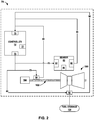
- FIG. 2 is a conceptual diagram illustrating an example optical system 70, in accordance with one or more aspects of the present disclosure.
- Optical system 70 is an example of optical system 22 of FIG. 1 .
- Optical system 70 includes a controller 72, a first sensor 82, a second sensor 90, and an actuator 92.
- Controller 72 includes an optical transmitter 73, an optical receiver 75, and processing circuitry 77.
- First sensor 82 includes an optical receiver 84, processing circuitry 86, and an optical transmitter 88.
- Second sensor 90 and actuator 92 similarly include a respective optical receiver, processing circuitry, and optical transmitter, although these components are not illustrated in FIG. 2 for clarity.
- Optical transmitter 73 of controller 72 is optically coupled to optical receiver 84 of first sensor 82 by first optical connection 76.
- Optical transmitter 73 of controller 72 is optically coupled to the optical receiver of second sensor 90 by second optical connection 78.
- Optical transmitter 73 of controller 72 is optically coupled to the optical receiver of actuator 92 by third optical connection 80.
- controller 72 may include a separate optical transmitter for each optical connection, e.g., a separate optical transmitter for each of first optical connection 76, second optical connection 78, and third optical connection 80.
- optical transmitter 73 may include any suitable device configured to output an optical signal with a predetermined frequency spectrum, such as an LED or a VCSEL.
- Optical receiver 75 of controller 72 is optically coupled to optical transmitter 88 of first sensor 82 via fourth optical connection 94.
- optical receiver of controller 72 is optically coupled to the optical transmitters of second sensor 90 and actuator 92 via fifth optical connection 96 and sixth optical connection 98, respectively.
- the send and receive channels for each respective device pair may be accomplished using a single optical connection.
- a single optical connection may optically couple controller 72 and first sensor 82.
- a transmit/receive pair may be optically coupled using a plurality of optical connections.
- Each optical connection may include a fiber optic cable.
- the plurality of optical connections if present, may be accomplished using separate fiber optical cables or separate modes of a multimode fiber.
- Controller 72 may include processing circuitry 77, a memory, and input/output hardware, including optical transmitter 73 and optical receiver 75.
- processing circuitry 77 may include any one or more of a microcontroller (MCU), e.g., a computer on a single integrated circuit containing a processor core, memory, and programmable input/output peripheral; a microprocessor ( ⁇ P); e.g. a central processing unit (CPU) on a single integrated circuit (IC); a digital signal processor (DSP); an application specific integrated circuit (ASIC); a field-programmable gate array (FPGA); a system on chip (SoC) or equivalent discrete or integrated logic circuitry.
- MCU microcontroller
- ⁇ P microprocessor
- CPU central processing unit
- DSP digital signal processor
- ASIC application specific integrated circuit
- FPGA field-programmable gate array
- SoC system on chip
- a processor may be integrated circuitry, i.e., integrated processing circuitry, and that the integrated processing circuitry may be realized as fixed hardware processing circuitry, programmable processing circuitry and/or a combination of both fixed and programmable processing circuitry.
- controller 72 and/or processing circuitry may include an engine control unit (ECU) or a full authority digital engine control (FADEC).
- ECU engine control unit
- FADEC full authority digital engine control
- Processing circuitry 77 may be configured to at least one of perform the functions ascribed to controller 72; process information received from sensors 82 and 90 and actuator 92 via optical receiver 75 and optical connections 94, 96, and 82; transmit information to sensors 82 and 90 and actuator 92 via optical transmitter 73 and optical connections 76, 78, and 80; and process a received optical signal to determine at least one optical characteristic of the received optical signal and compare the at least one optical characteristic of the received optical signal to at least one optical characteristic associated with an optical transmitter of first sensor 82, second sensor 90, or actuator 92.
- Optical transmitter 73 may include any of the optical transmitters described herein, including an LED or a VCSEL.
- Optical receiver 75 may include any of the optical receivers described herein, including photodiode or the like.
- First sensor 82 may include any suitable type of sensor.
- first sensor 82 may include a temperature sensor, a pressure sensor, a position sensor, a speed sensor, a rotational frequency sensor, an accelerometer, a gyroscope, a gas detector, a proximity sensor, or the like.
- First sensor 82 may include a sensor component configured to perform the sensing aspect of first sensor 82, and also may include input/output components, such as optical receiver 84 and optical transmitter 88, and processing circuitry 86.
- Optical transmitter 88 may include any of the optical transmitters described herein, including an LED or a VCSEL.
- Optical receiver 84 may include any of the optical receivers described herein, including photodiode or the like.
- Processing circuitry 86 may include any one or more of a MCU, a ⁇ P, a DSP, an ASIC, a FPGA, a SoC, or equivalent discrete or integrated logic circuitry. Processing circuitry 86 may be configured to at least one of control the sensor component, process information received from the sensor component, receive and transmit data via optical receiver 84 and optical transmitter 88, respectively, and process a received optical signal to determine at least one optical characteristic of the received optical signal and compare the at least one optical characteristic of the received optical signal to at least one optical characteristic associated with optical transmitter 73 of controller 72.
- Second sensor 90 may be similar to or substantially the same as first sensor 82 in that second sensor 90 may include any suitable type of sensor and may include a sensor component configured to perform the sensing aspect of second sensor 90, input/output components, such as an optical receiver and an optical transmitter, and processing circuitry. Second sensor 90 may include the same or a different type of sensor component as first sensor 82. In the example of FIG. 2 , second sensor 90 may include a rotational frequency sensor configured to sense a rotational frequency or rotational speed of output shaft 102.
- Actuator 92 may include any type of actuator component configured to actuate any type of component.
- actuator 92 may include a hydraulic actuator, a pneumatic actuator, an electric actuator, or a mechanical actuator.
- Actuator 92 may be configured to actuate any type of component, such as a valve, a flap, a vane, a nozzle, (e.g., a valve actuator, a linear or rotational actuator, or the like).
- actuator 92 may include processing circuitry, an optical transmitter, an optical receiver.
- Optical system 70 is illustrated in FIG. 2 in the context of a gas turbine engine system, which includes a gas turbine engine 100 coupled to an output shaft 102, which drives a machine 104, such as a propulsor.
- Gas turbine engine 100 receives fuel from fuel storage 104 via actuator 92 (e.g., a valve).
- actuator 92 e.g., a valve
- optical system 70 may be used in any other context in which two devices communicate using optical signals over optical connections.
- At least one component of optical system 70 may store at least one optical characteristic of at least one optical transmitter that transmits optical signals to the component and use the at least one optical characteristic to verify integrity of received optical signals.
- controller 72 and first sensor 82 may store at least one optical characteristic of at least one optical transmitter that transmits optical signals to the component and use the at least one optical characteristic to verify integrity of received optical signals.
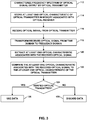
- FIG. 3 is a flow diagram illustrating example operations performed by optical system 70, in accordance with one or more aspects of the present disclosure. The techniques of FIG. 3 may be performed by optical systems including more or fewer components than are shown in FIG. 2 .
- the technique of FIG. 3 includes characterizing the frequency spectrum of an optical signal output by optical transmitter 73 (112).
- the frequency spectrum of the optical signal output by optical transmitter 73 may be characterized at the time of manufacture of optical transmitter 73 or at the time of installation of optical transmitter 73 in optical system 22 or gas turbine engine 20.
- at least one optical characteristic of the optical transmitter of first component 60 may be characterized.
- the at least one optical characteristic of the optical transmitter may be characterized by detecting the output optical signal, e.g., using a photodetector, and transforming the electrical signal output by the photodetector, which is representative of the optical signal, from the time domain to the frequency domain.
- processing circuitry such as processing circuitry 86, although other processing circuitry may be used
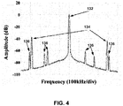
- FIG. 4 is a diagram illustrating an example LED emission spectrum in a frequency domain.
- the processing circuitry then may analyze the frequency domain representation of the electrical signal representative of the optical signal to identify at least one optical characteristic.
- the at least one optical characteristic may include, for example, an actual carrier frequency 132 of the optical signal output by optical transmitter 73.
- optical transmitter 73 may be labelled or assigned a nominal carrier frequency that generally describes an approximate center frequency of the light output by optical transmitter 73, manufacturing variations may result in the actual carrier frequency 132 varying from the nominal carrier frequency when analyzed with sufficient precision. Manufacturing variations may result in the actual carrier frequency 132 being substantially unique to optical transmitter 73.
- the at least one optical characteristic may include a phase modulation sideband frequency or frequencies 134. Like the actual carrier frequency 132, the phase modulation sideband frequency or frequencies 134 may be substantially unique to optical transmitter 73 when analyzed with sufficient precision due to manufacturing variations. As other examples, the at least one optical characteristic may include an amplitude of the optical signal at an actual carrier frequency 132 of the optical signal or an amplitude of the optical signal at a phase modulation sideband frequency or frequencies 134. Although the at least one optical characteristic is generally described herein as a frequency, the at least one optical characteristic alternatively may be determined as a wavelength.
- the at least one optical characteristic may include multiple, different frequencies to more fully define the optical signal output by optical transmitter 73.
- the at least one optical characteristic may include an actual carrier frequency 132 and a phase modulation sideband frequency or frequencies 134, and optionally may include additional frequencies, such as any frequencies having an amplitude above a threshold value.
- additional frequencies 136 may be included in the at least one optical characteristic to more fully characterize the optical signal output by optical transmitter 73.
- controller 72 and first sensor 82 may be connected by multiple optical connections or a multimode optical connection so that optical receiver 84 (either one or multiple optical receivers) receive a plurality of optical signals from optical transmitter 73 (either one or multiple optical transmitters).
- the at least one optical characteristic may include a beat of two or more optical signals (e.g., a frequency of constructive interference between the two or more optical signals).
- the at least one optical characteristic of optical transmitter may be stored in a memory associated with optical receiver 84 to which optical transmitter 73 is optically coupled (114).
- the memory may be part of processing circuitry 86.
- the memory may include one or more security features to protect data stored in the memory, such as read-only setting, anti-tampering procedures, or the like.
- first sensor 82 may be configured to analyze optical signals received from controller 72, identify at least one optical characteristic of the received optical signal, and determine whether the optical signal is from a verified optical transmitter based on the at least one optical characteristic of the received optical signal and the at least one optical characteristic associated with the originally-installed optical transmitter 73 of controller 72.
- optical receiver 84 may receive an optical signal (116).
- Optical receiver 84 may convert the received optical signal to an electrical signal representative of the received optical signal.
- the electrical signal may be receiver from optical receiver 84 by processing circuitry 86.
- Processing circuitry 86 may transform the electrical signal from the time domain to a frequency domain (118), then may extract at least one optical characteristic of the received signal from the electrical signal that is representative of the received optical signal (120). For example, processing circuitry 86 may identify an actual carrier signal frequency or wavelength, a phase modulation sideband frequency or wavelength, at least one additional frequency having an amplitude above a threshold value, a frequency of constructive interference between two received optical signals, or the like.
- Processing circuitry 86 may compare the at least one optical characteristic of the received signal to the at least one optical characteristic of optical transmitter 73 stored in the memory associated with optical receiver 84 (122). In response to the at least one optical characteristic of the received optical signal being substantially the same (e.g., the same or the same within a predetermined threshold amount) as the at least one optical characteristic associated with the originally installed optical transmitter 73, processing circuitry may determine that optical system 22 (or at least the optical transmitter 73 and optical connection 76) is intact and the optical transmitter that transmitted the optical signal is verified to be optical transmitter 73 (the "YES" branch of decision block 124). First sensor 82 (e.g., processing circuitry 86) may proceed to use the data contained in the received optical signal (126).
- First sensor 82 e.g., processing circuitry 86
- processing circuitry 86 may determine that optical system 22 (or at least one of the optical transmitter sending the optical signal or optical link 76) is not intact and the optical transmitter that sent the optical signal is not a verified optical transmitter (the "NO" branch of decision block (124)).
- First sensor 82 e.g., processing circuitry 86
- first sensor 82 e.g., processing circuitry 86 additionally may communicate an indication that optical system 22 (or at least one of the optical transmitter or optical link 76) is not intact.
- processing circuitry 86 may send an indication to controller 72 using optical transmitter 88.
- this technique may be used bi-directionally (e.g., from controller 72 to first sensor 82 and from first sensor 82 to controller 72). Additionally, this technique may be used for any pair or set of optical transmitter(s) and optical receiver(s) in optical system 70.
- optical receiver 84 may detect data originating from devices other than optical transmitter 73. This may increase security of optical system 70and reduce a likelihood of successful attacks on optical system 70 using man-in-the-middle attacks or replacement of optical transmitter 73.
Landscapes
- Engineering & Computer Science (AREA)
- Computer Security & Cryptography (AREA)
- Computer Networks & Wireless Communication (AREA)
- Signal Processing (AREA)
- Physics & Mathematics (AREA)
- Electromagnetism (AREA)
- Computer Hardware Design (AREA)
- Computing Systems (AREA)
- General Engineering & Computer Science (AREA)
- Optical Communication System (AREA)
Abstract
Description
- The disclosure relates to optical systems and security features for frequency-based communications systems.
- Embedded electrical and computing systems are used in many applications, including manned and unmanned vehicle control systems, as well as other types of control systems. For instance, flight control systems, engine control systems, generator control systems, and the like, are examples of embedded electrical and computing systems. These types of embedded systems may be exposed, during regular operational use, to a variety of different types of hostile cyberattacks. For example, an unauthorized user may try to circumvent access controls to take command of an engine control system of an aircraft, e.g., to induce damage to the engine, or worse, crash the aircraft.
- In one example, the disclosure is directed to a method including: receiving, by a receiver, from a transmitter, a communications signal; determining, by processing circuitry, at least one frequency characteristic of the communications signal; and determining, by the processing circuitry, whether the transmitter is a verified transmitter based on the at least one frequency characteristic and at least one verified frequency characteristic stored by a memory associated with the processing circuitry.
- The receiver may detect data originating from devices other than the transmitter. This may increase security of a system and reduce a likelihood of successful attacks on the system using man-in-the-middle attacks or replacement of the transmitter.
- In some embodiments, the receiver includes an optical receiver, the transmitter includes an optical transmitter, the communications signal includes an optical signal, and the optical signal encodes data.
- In some embodiments, the at least one frequency characteristic includes an actual carrier frequency of the communications signal.
- The actual carrier frequency of the communications signal emitted by the transmitter may be different from a nominal carrier frequency and may be unique to the transmitter when determined to a sufficient level of precision.
- In some embodiments, the at least one frequency characteristic includes a phase modulation sideband frequency of the communications signal.
- The phase modulation sideband frequency of the communications signal may be unique to the transmitter when determined to a sufficient level of precision.
- In some embodiments, the at least one frequency characteristic includes an amplitude of the optical signal at an actual carrier frequency of the communications signal.
- In some embodiments, the at least one frequency characteristic includes an amplitude of the communications signal at a phase modulation sideband frequency.
- In some embodiments, the communications signal is a first communications signal. The method further includes receiving a second communications signal. Determining the at least one frequency characteristic includes determining a frequency of constructive interference between the first communications signal and the second communications signal.
- In some embodiments, the method further includes outputting, by the processing circuitry, an indication of the whether the transmitter is a verified transmitter.
- In some embodiments, the method further includes, in response to determining that the transmitter is not a verified transmitter, discarding data encoded in the communications signal.
- In some embodiments, the method further includes, in response to determining that the transmitter is a verified transmitter, decoding data encoded in the communications signal.
- In another example, the disclosure is directed to a system including: a receiver configured to receive a communications signal from a transmitter; and processing circuitry configured to: determine at least one frequency characteristic of the communications signal; and determine whether the transmitter is a verified transmitter based on the at least one frequency characteristic and at least one verified frequency characteristic stored by a memory associated with the processing circuitry.
- The receiver and the processing circuitry may verify integrity of the communications link between the transmitter and receiver, reducing a likelihood of success of intrusion in the system by attackers. This may be particularly applicable to embedded electrical and computing systems, such as those used in flight control systems, engine control systems, generator control systems, and the like.
- In some embodiments, the receiver includes an optical receiver, the transmitter includes an optical transmitter, the communications signal includes an optical signal, and the optical signal encodes data.
- In some embodiments, the at least one frequency characteristic includes an actual carrier frequency of the communications signal.
- In some embodiments, the at least one frequency characteristic includes a phase modulation sideband frequency of the communications signal.
- In some embodiments, the at least one frequency characteristic includes an amplitude of the communications signal at an actual carrier frequency of the communications signal.
- In some embodiments, the at least one frequency characteristic includes an amplitude of the communications signal at a phase modulation sideband frequency.
- In some embodiments, the communications signal is a first communications signal. The processing circuitry is configured to determine the at least one frequency characteristic by determining a frequency of constructive interference between the first communications signal and a second communications signal.
- In some embodiments, the processing circuitry is further configured to output an indication of the whether the transmitter is a verified transmitter.
- In some embodiments, the processing circuitry is further configured to, in response to determining that the transmitter is not a verified transmitter, discard data encoded in the communications signal.
- In some embodiments, the processing circuitry is further configured to, in response to determining that the transmitter is a verified transmitter, decode data encoded in the communications signal.
- The details of one or more examples are set forth in the accompanying drawings and the description below. Other features, objects, and advantages of the disclosure will be apparent from the description and drawings, and from the claims.
-
FIG. 1 is a conceptual diagram illustrating an example gas turbine engine that includes an optical system, in accordance with one or more aspects of the present disclosure. -
FIG. 2 is a conceptual diagram illustrating an example optical system, in accordance with one or more aspects of the present disclosure. -
FIG. 3 is a flow diagram illustrating example operations performed by an example optical system that includes an optical receiver and processing circuitry, in accordance with one or more aspects of the present disclosure. -
FIG. 4 is a diagram illustrating an example light emitting diode emission spectrum. - The disclosure describes frequency spectrum-based communications systems including a receiver and a transmitter that are keyed to each other using information based on at least one frequency characteristic of the transmitter. In some examples, the frequency spectrum-based communications system may be an optical communications system. In other examples, the frequency spectrum-based communications system may be a radio frequency (RF) communications system. The transmitter outputs a communications signal, such as a pulse train, to transmit data from the transmitter to the receiver. The transmitter outputs the communications signal as electromagnetic energy with a predetermined frequency spectrum. While the transmitter may be associated with a nominal carrier frequency, the actual communications signal emitted by the transmitter may be unique to the specific transmitter when analyzed with sufficient precision. For example, the actual carrier frequency of the communications signal emitted by the transmitter may be different from the nominal carrier frequency and unique to the transmitter when determined to a sufficient level of precision. As another example, the frequency of a phase modulation sideband may be unique to the transmitter when determined to a sufficient level of precision.
- By determining at least one frequency characteristic of a transmitter, a security key may be generated. The security key may be stored in a memory associated with a corresponding receiver to which the transmitter is communicatively coupled, e.g., during manufacture or installation of the communication system. The security key (the at least one frequency characteristic of the optical transmitter) may identify a verified transmitter. During use, processing circuitry associated with the receiver may determine at least one frequency characteristic of a received communications signal. The processing circuitry may determine whether the received communications signal was output by the verified transmitter based on the at least one frequency characteristic of the received communications signal and the stored at least one frequency characteristic associated with the verified transmitter determine whether the received communications signal was output by the verified transmitter. In this way, the receiver and associated processing circuitry may verify integrity of the communications link between the transmitter and receiver, reducing a likelihood of success of intrusion in the system by attackers. This may be particularly applicable to embedded electrical and computing systems, such as those used in flight control systems, engine control systems, generator control systems, and the like.
- The following examples will be described with primary reference to an optical communication system in which the transmitter and receiver are an optical transmitter and an optical receiver, and the communication coupling between the transmitter and receiver is an optical connection, such as a fiber optic cable. It will be understood, however, that the systems and techniques described herein may be applied to other frequency-based communications systems, such as, for example RF communication systems.
-
FIG. 1 is a conceptual diagram illustrating an examplegas turbine engine 20 that includes an optical system 22, in accordance with one or more aspects of the present disclosure.Gas turbine engine 20 is a primary propulsion engine that provides thrust for flight operations of a vehicle, such as an aircraft, marine craft, or the like. In some examples,gas turbine engine 20 is a two-spool engine having a high pressure (HP)spool 24 and a low pressure (LP)spool 26. In other examples,gas turbine engine 20 may include three or more spools, e.g., may include an intermediate pressure (IP) spool and/or other spools. In some examples,gas turbine engine 20 is a turbofan engine, whereinLP spool 26 is operative to drive a propulsor in the form of a turbofan (fan)system 28. In other examples,gas turbine engine 20 may not include a LP spool orfan system 28. In some examples,gas turbine engine 20 may include any suitable turbine powered-engine propulsion system, including but not limited to, a turbojet engine or a turboprop engine. -
Gas turbine engine 20 includes afan system 28 in fluid communication with abypass duct 30 and acompressor system 32. Adiffuser 34 is in fluid communication withcompressor system 32. A combustion system 36 is fluidically disposed betweencompressor system 32 and a high pressure (HP) turbine system 38 (e.g., disposed betweencompressor system 32 andHP turbine system 38 such that air or another fluid may flow fromcompressor system 32 to combustion system 36 to HP turbine system 38). In some examples, combustion system 36 includes a combustion liner (not shown) that encloses a continuous combustion process. In other examples, combustion system 36 may take other forms, and may be, for example, a wave rotor combustion system, a rotary valve combustion system, a pulse detonation combustion system, or a slinger combustion system, and may employ deflagration and/or detonation combustion processes. A low pressure (LP)turbine system 40 is fluidically disposed betweenHP turbine system 38 and anozzle 42A configured to discharge a core flow of gas turbine engine 20 (e.g., disposed betweenHP turbine system 38 andnozzle 42A such that air or another fluid may flow fromHP turbine system 38 toLP turbine system 40 tonozzle 42A). Anozzle 42B is in fluid communication withbypass duct 30, and operative to transmit a bypass flow generated byfan system 28 around the core ofgas turbine engine 20. In other examples, other nozzle arrangements may be used, e.g., a common nozzle for core and bypass flow; a nozzle for core flow, but no nozzle for bypass flow; or another nozzle arrangement. -
Fan system 28 includes afan rotor system 48 having one or more rotors (not shown) that are driven byLP spool 26 ofLP turbine system 40.Fan system 28 may include one or more vanes (not shown).Compressor system 32 includes acompressor rotor system 50. In some examples,compressor rotor system 50 includes one or more rotors (not shown) that are powered byHP turbine system 38. Highpressure turbine system 38 includes a firstturbine rotor system 52. Firstturbine rotor system 52 includes one or more rotors (not shown) operative to drivecompressor rotor system 50. Firstturbine rotor system 52 is drivingly coupled tocompressor rotor system 50 via ashafting system 54. Lowpressure turbine system 40 includes a secondturbine rotor system 56. Secondturbine rotor system 56 includes one or more rotors (not shown) operative to drivefan rotor system 48. Secondturbine rotor system 56 is drivingly coupled tofan rotor system 48 via ashafting system 58.Shafting systems systems Turbine system 40 is operative to discharge theengine 20 core flow tonozzle 42A. - During normal operation of
gas turbine engine 20, air is drawn into the inlet offan system 28 and pressurized byfan rotor system 48. Some of the air pressurized byfan rotor system 48 is directed intocompressor system 32 as core flow, and some of the pressurized air is directed intobypass duct 30 as bypass flow.Compressor system 32 further pressurizes the portion of the air received therein fromfan system 28, which is then discharged intodiffuser 34.Diffuser 34 reduces the velocity of the pressurized air and directs the diffused core airflow into combustion system 36. Fuel is mixed with the pressurized air in combustion system 36, which is then combusted. The hot gases exiting combustion system 36 are directed intoturbine systems compressor system 32 andfan system 28 viarespective shafting systems - In some examples,
engine 20 may include anelectrical machine 44 coupled toLP spool 26, anelectrical machine 46 coupled toHP spool 24, or both.Electrical machine 44 andelectrical machine 46 may be configured to provide electrical power to aircraft during flight operations, during ground operations, or both. In some examples, each ofelectrical machines electrical machines electrical machines - Optical system 22 of
gas turbine engine 20 includes afirst component 60 and asecond component 62.First component 60 and second component are optically coupled by an optical interface, such as a fiber optic cable (not labelled inFIG. 1 ).First component 60 may be a central component, such as a controller. Second component 64 may include a remote component, such as a sensor (e.g., temperature, pressure, position, speed, rotational frequency, or the like) or an actuator (e.g., a valve actuator, a linear or rotational actuator, or the like). In this way, optical system 22 may be part or substantially all of a control system forgas turbine engine 20. - Although optical system 22 is illustrated in the context of
gas turbine engine 20 inFIG. 1 , optical system 22 may be used in any optical-communications based system, including other control system, networking systems, and the like. -
First component 60 includes anoptical transceiver 62.Optical transceiver 62 may include an optical transmitter and an optical receiver. Alternatively,first component 60 may include separate optical transmitter and optical receiver. Similarly, second component 64 may include an optical transceiver or an optical transmitter and optical receiver. - The optical transmitter may include any light source configured to output light with a selected frequency spectrum. In some examples, the optical transmitter may include a light emitting diode (LED), a vertical cavity surface emitting laser (VCSEL), or the like. In other examples, the optical transmitter may include a plurality of LEDs or VCSELs, each LED or VCSEL outputting light with a different frequency spectrum.
- The optical receiver may include any photo detector configured to sense light and produce an electrical signal representative of the sensed light. For example, the optical receiver may include a photodiode or the like.
- Although not shown in
FIG. 1 , each offirst component 60 and second component 64 may also include processing circuitry configured to process the electrical signal indicative of the sensed light and to generate electrical signals that the optical transmitter converts to optical signals and outputs. - In accordance with aspects of this disclosure, at least one optical characteristic of at least one of the optical transmitters may be characterized at the time of manufacture of the optical transmitter or at the time of installation of the optical transmitter in optical system 22 or
gas turbine engine 20. For example, at least one optical characteristic of the optical transmitter offirst component 60 may be characterized. The at least one optical characteristic may include, for example, an actual carrier frequency of the optical signal output by the optical transmitter. Although an optical transmitter may be assigned a nominal carrier frequency that generally describes an approximate center frequency of the light output by the optical transmitter, manufacturing variations may result in the actual carrier frequency varying from the nominal carrier frequency when analyzed with sufficient precision. Manufacturing variations may result in the actual carrier frequency being substantially unique to the respective optical transmitter. - As another example, the at least one optical characteristic may include a phase modulation sideband frequency. Like the actual carrier frequency, the phase modulation sideband frequency may be substantially unique to the respective optical transmitter when analyzed with sufficient precision due to manufacturing variations. As other examples, the at least one optical characteristic may include an amplitude of the optical signal at an actual carrier frequency of the optical signal or an amplitude of the optical signal at a phase modulation sideband frequency.
- The at least one optical characteristic of the optical transmitter may be stored in a memory associated with the optical receiver to which the optical transmitter is optically coupled. For example, if the characterized optical transmitter is part of
optical transceiver 62 offirst component 60, the at least one optical characteristic of the optical transmitter may be stored in a memory associated with the optical receiver of second component 64. During operation of optical system 22, second component 64 may be configured to analyze optical signals received fromfirst component 60, identify at least one optical characteristic of the received optical signal, and compare the at least one optical characteristic of the received optical signal to the stored at least one optical characteristic associated with the originally-installed optical transmitter offirst component 60. In response to the at least one optical characteristic of the received optical signal being substantially the same (e.g., the same or the same within a predetermined threshold amount) as the at least one optical characteristic associated with the originally installed optical transmitter, second component 64 may determine that optical system 22 (or at least the optical transmitter offirst component 60 and the optical link between the optical transmitter offirst component 60 and the optical receiver of second component 64) is intact and the optical signal is genuine. Second component 64 may proceed to use the data contained in the optical signal. On the other hand, in response to the at least one optical characteristic of the received optical signal not being substantially the same (e.g., not the same or not the same within a predetermined threshold amount) as the at least one optical characteristic associated with the originally installed optical transmitter, second component 64 may determine that optical system 22 (or that at least one of the optical transmitter offirst component 60 or the optical link between the optical transmitter offirst component 60 and the optical receiver of second component 64) is not intact. Second component 64 may proceed to discard or not use the data contained in the optical signal. In some examples, second component 64 additionally may communicate an indication that optical system 22 (or that at least one of the optical transmitter offirst component 60 or the optical link between the optical transmitter offirst component 60 and the optical receiver of second component 64) is not intact. - Although the characterization and storing of at least one optical characteristic has been described in only one direction (from
first component 60 to second component 64), this technique may be used bi-directionally (e.g., fromfirst component 60 to second component 64 and from second component 64 to first component 60). - In this way, by characterizing the optical signal output by a specific optical transmitter when manufacturing the optical transmitter or installing the optical transmitter in optical system 22 and storing the at least one optical characteristic in a memory associated with an optical receiver optically coupled to the optical transmitter, the optical receiver may detect data originating from devices other than the optical transmitter. This may increase security of optical system 22 and reduce a likelihood of successful attacks on optical system 22 using man-in-the-middle attacks or replacement of an optical transmitter.
-
FIG. 2 is a conceptual diagram illustrating an exampleoptical system 70, in accordance with one or more aspects of the present disclosure.Optical system 70 is an example of optical system 22 ofFIG. 1 .Optical system 70 includes acontroller 72, afirst sensor 82, asecond sensor 90, and anactuator 92.Controller 72 includes anoptical transmitter 73, anoptical receiver 75, andprocessing circuitry 77.First sensor 82 includes anoptical receiver 84, processingcircuitry 86, and anoptical transmitter 88.Second sensor 90 andactuator 92 similarly include a respective optical receiver, processing circuitry, and optical transmitter, although these components are not illustrated inFIG. 2 for clarity. -
Optical transmitter 73 ofcontroller 72 is optically coupled tooptical receiver 84 offirst sensor 82 by firstoptical connection 76.Optical transmitter 73 ofcontroller 72 is optically coupled to the optical receiver ofsecond sensor 90 by secondoptical connection 78.Optical transmitter 73 ofcontroller 72 is optically coupled to the optical receiver ofactuator 92 by thirdoptical connection 80. Althoughoptical transmitter 73 is shown as a single optical transmitter, in other examples,controller 72 may include a separate optical transmitter for each optical connection, e.g., a separate optical transmitter for each of firstoptical connection 76, secondoptical connection 78, and thirdoptical connection 80. Like the optical transmitters described inFIG. 1 ,optical transmitter 73 may include any suitable device configured to output an optical signal with a predetermined frequency spectrum, such as an LED or a VCSEL. -
Optical receiver 75 ofcontroller 72 is optically coupled tooptical transmitter 88 offirst sensor 82 via fourthoptical connection 94. Similarly, optical receiver ofcontroller 72 is optically coupled to the optical transmitters ofsecond sensor 90 andactuator 92 via fifthoptical connection 96 and sixthoptical connection 98, respectively. In other examples, rather than the optical connections for the send (optical transmitters) and receive (optical receivers) channels being separate optical connections, the send and receive channels for each respective device pair may be accomplished using a single optical connection. For example, a single optical connection may optically couplecontroller 72 andfirst sensor 82. Alternatively, rather than a single optical connection optically connecting a transmit/receive pair, a transmit/receive pair may be optically coupled using a plurality of optical connections. Each optical connection may include a fiber optic cable. The plurality of optical connections, if present, may be accomplished using separate fiber optical cables or separate modes of a multimode fiber. -
Controller 72 may include processingcircuitry 77, a memory, and input/output hardware, includingoptical transmitter 73 andoptical receiver 75. Examples of processingcircuitry 77 may include any one or more of a microcontroller (MCU), e.g., a computer on a single integrated circuit containing a processor core, memory, and programmable input/output peripheral; a microprocessor (µP); e.g. a central processing unit (CPU) on a single integrated circuit (IC); a digital signal processor (DSP); an application specific integrated circuit (ASIC); a field-programmable gate array (FPGA); a system on chip (SoC) or equivalent discrete or integrated logic circuitry. A processor may be integrated circuitry, i.e., integrated processing circuitry, and that the integrated processing circuitry may be realized as fixed hardware processing circuitry, programmable processing circuitry and/or a combination of both fixed and programmable processing circuitry. In some examples,controller 72 and/or processing circuitry may include an engine control unit (ECU) or a full authority digital engine control (FADEC). -
Processing circuitry 77 may be configured to at least one of perform the functions ascribed tocontroller 72; process information received fromsensors actuator 92 viaoptical receiver 75 andoptical connections sensors actuator 92 viaoptical transmitter 73 andoptical connections first sensor 82,second sensor 90, oractuator 92.Optical transmitter 73 may include any of the optical transmitters described herein, including an LED or a VCSEL.Optical receiver 75 may include any of the optical receivers described herein, including photodiode or the like. -
First sensor 82 may include any suitable type of sensor. For examples,first sensor 82 may include a temperature sensor, a pressure sensor, a position sensor, a speed sensor, a rotational frequency sensor, an accelerometer, a gyroscope, a gas detector, a proximity sensor, or the like.First sensor 82 may include a sensor component configured to perform the sensing aspect offirst sensor 82, and also may include input/output components, such asoptical receiver 84 andoptical transmitter 88, andprocessing circuitry 86.Optical transmitter 88 may include any of the optical transmitters described herein, including an LED or a VCSEL.Optical receiver 84 may include any of the optical receivers described herein, including photodiode or the like. -
Processing circuitry 86 may include any one or more of a MCU, a µP, a DSP, an ASIC, a FPGA, a SoC, or equivalent discrete or integrated logic circuitry.Processing circuitry 86 may be configured to at least one of control the sensor component, process information received from the sensor component, receive and transmit data viaoptical receiver 84 andoptical transmitter 88, respectively, and process a received optical signal to determine at least one optical characteristic of the received optical signal and compare the at least one optical characteristic of the received optical signal to at least one optical characteristic associated withoptical transmitter 73 ofcontroller 72. -
Second sensor 90 may be similar to or substantially the same asfirst sensor 82 in thatsecond sensor 90 may include any suitable type of sensor and may include a sensor component configured to perform the sensing aspect ofsecond sensor 90, input/output components, such as an optical receiver and an optical transmitter, and processing circuitry.Second sensor 90 may include the same or a different type of sensor component asfirst sensor 82. In the example ofFIG. 2 ,second sensor 90 may include a rotational frequency sensor configured to sense a rotational frequency or rotational speed ofoutput shaft 102. -
Actuator 92 may include any type of actuator component configured to actuate any type of component. For example,actuator 92 may include a hydraulic actuator, a pneumatic actuator, an electric actuator, or a mechanical actuator.Actuator 92 may be configured to actuate any type of component, such as a valve, a flap, a vane, a nozzle, (e.g., a valve actuator, a linear or rotational actuator, or the like). Likesensors actuator 92 may include processing circuitry, an optical transmitter, an optical receiver. -
Optical system 70 is illustrated inFIG. 2 in the context of a gas turbine engine system, which includes agas turbine engine 100 coupled to anoutput shaft 102, which drives amachine 104, such as a propulsor.Gas turbine engine 100 receives fuel fromfuel storage 104 via actuator 92 (e.g., a valve). However,optical system 70 may be used in any other context in which two devices communicate using optical signals over optical connections. - As described above with respect to
FIG. 1 , at least one component of optical system 70 (e.g.,controller 72,first sensor 82,second sensor 90, or actuator 92) may store at least one optical characteristic of at least one optical transmitter that transmits optical signals to the component and use the at least one optical characteristic to verify integrity of received optical signals. The following example will be described with reference tocontroller 72 andfirst sensor 82, but it will be understood that similar techniques may be applied by in the reverse direction betweencontroller 72 andfirst sensor 82, bysecond sensor 90 and/oractuator 92, or combinations thereof. Further, the following example will be described with respect toFIG. 3 , which is a flow diagram illustrating example operations performed byoptical system 70, in accordance with one or more aspects of the present disclosure. The techniques ofFIG. 3 may be performed by optical systems including more or fewer components than are shown inFIG. 2 . - The technique of
FIG. 3 includes characterizing the frequency spectrum of an optical signal output by optical transmitter 73 (112). In some examples, the frequency spectrum of the optical signal output byoptical transmitter 73 may be characterized at the time of manufacture ofoptical transmitter 73 or at the time of installation ofoptical transmitter 73 in optical system 22 orgas turbine engine 20. For example, at least one optical characteristic of the optical transmitter offirst component 60 may be characterized. - The at least one optical characteristic of the optical transmitter may be characterized by detecting the output optical signal, e.g., using a photodetector, and transforming the electrical signal output by the photodetector, which is representative of the optical signal, from the time domain to the frequency domain. For example, processing circuitry (such as
processing circuitry 86, although other processing circuitry may be used) may apply a Fourier Transform, Laplace transform, Z-transform, or other mathematical algorithm to transform the electrical signal representative of the optical signal from the time domain to a frequency domain.FIG. 4 is a diagram illustrating an example LED emission spectrum in a frequency domain. - The processing circuitry then may analyze the frequency domain representation of the electrical signal representative of the optical signal to identify at least one optical characteristic. The at least one optical characteristic may include, for example, an
actual carrier frequency 132 of the optical signal output byoptical transmitter 73. As described above, althoughoptical transmitter 73 may be labelled or assigned a nominal carrier frequency that generally describes an approximate center frequency of the light output byoptical transmitter 73, manufacturing variations may result in theactual carrier frequency 132 varying from the nominal carrier frequency when analyzed with sufficient precision. Manufacturing variations may result in theactual carrier frequency 132 being substantially unique tooptical transmitter 73. - As another example, the at least one optical characteristic may include a phase modulation sideband frequency or
frequencies 134. Like theactual carrier frequency 132, the phase modulation sideband frequency orfrequencies 134 may be substantially unique tooptical transmitter 73 when analyzed with sufficient precision due to manufacturing variations. As other examples, the at least one optical characteristic may include an amplitude of the optical signal at anactual carrier frequency 132 of the optical signal or an amplitude of the optical signal at a phase modulation sideband frequency orfrequencies 134. Although the at least one optical characteristic is generally described herein as a frequency, the at least one optical characteristic alternatively may be determined as a wavelength. - In some examples, the at least one optical characteristic may include multiple, different frequencies to more fully define the optical signal output by
optical transmitter 73. For example, the at least one optical characteristic may include anactual carrier frequency 132 and a phase modulation sideband frequency orfrequencies 134, and optionally may include additional frequencies, such as any frequencies having an amplitude above a threshold value. For example,additional frequencies 136 may be included in the at least one optical characteristic to more fully characterize the optical signal output byoptical transmitter 73. - In some examples, as described with reference to
FIG. 2 ,controller 72 andfirst sensor 82 may be connected by multiple optical connections or a multimode optical connection so that optical receiver 84 (either one or multiple optical receivers) receive a plurality of optical signals from optical transmitter 73 (either one or multiple optical transmitters). In some such examples, the at least one optical characteristic may include a beat of two or more optical signals (e.g., a frequency of constructive interference between the two or more optical signals). - The at least one optical characteristic of optical transmitter may be stored in a memory associated with
optical receiver 84 to whichoptical transmitter 73 is optically coupled (114). For example, the memory may be part ofprocessing circuitry 86. In some examples, the memory may include one or more security features to protect data stored in the memory, such as read-only setting, anti-tampering procedures, or the like. - During operation of optical system 22,
first sensor 82 may be configured to analyze optical signals received fromcontroller 72, identify at least one optical characteristic of the received optical signal, and determine whether the optical signal is from a verified optical transmitter based on the at least one optical characteristic of the received optical signal and the at least one optical characteristic associated with the originally-installedoptical transmitter 73 ofcontroller 72. For example,optical receiver 84 may receive an optical signal (116).Optical receiver 84 may convert the received optical signal to an electrical signal representative of the received optical signal. The electrical signal may be receiver fromoptical receiver 84 by processingcircuitry 86. -
Processing circuitry 86 may transform the electrical signal from the time domain to a frequency domain (118), then may extract at least one optical characteristic of the received signal from the electrical signal that is representative of the received optical signal (120). For example, processingcircuitry 86 may identify an actual carrier signal frequency or wavelength, a phase modulation sideband frequency or wavelength, at least one additional frequency having an amplitude above a threshold value, a frequency of constructive interference between two received optical signals, or the like. -
Processing circuitry 86 may compare the at least one optical characteristic of the received signal to the at least one optical characteristic ofoptical transmitter 73 stored in the memory associated with optical receiver 84 (122). In response to the at least one optical characteristic of the received optical signal being substantially the same (e.g., the same or the same within a predetermined threshold amount) as the at least one optical characteristic associated with the originally installedoptical transmitter 73, processing circuitry may determine that optical system 22 (or at least theoptical transmitter 73 and optical connection 76) is intact and the optical transmitter that transmitted the optical signal is verified to be optical transmitter 73 (the "YES" branch of decision block 124). First sensor 82 (e.g., processing circuitry 86) may proceed to use the data contained in the received optical signal (126). - On the other hand, in response to the at least one optical characteristic of the received optical signal not being substantially the same (e.g., not the same or not the same within a predetermined threshold amount) as the at least one optical characteristic associated with the originally installed
optical transmitter 73, processingcircuitry 86 may determine that optical system 22 (or at least one of the optical transmitter sending the optical signal or optical link 76) is not intact and the optical transmitter that sent the optical signal is not a verified optical transmitter (the "NO" branch of decision block (124)). First sensor 82 (e.g., processing circuitry 86) may proceed to discard or not use the data contained in the received optical signal (128). In some examples, first sensor 82 (e.g., processing circuitry 86) additionally may communicate an indication that optical system 22 (or at least one of the optical transmitter or optical link 76) is not intact. For example, processingcircuitry 86 may send an indication tocontroller 72 usingoptical transmitter 88. - Although the characterization and storing of at least one optical characteristic has been described in only one direction (from
controller 72 to first sensor 82), this technique may be used bi-directionally (e.g., fromcontroller 72 tofirst sensor 82 and fromfirst sensor 82 to controller 72). Additionally, this technique may be used for any pair or set of optical transmitter(s) and optical receiver(s) inoptical system 70. - In this way, by characterizing the optical signal output by a specific optical transmitter when manufacturing
optical transmitter 73 or installingoptical transmitter 73 inoptical system 70 and storing the at least one optical characteristic in a memory associated withoptical receiver 84,optical receiver 84 may detect data originating from devices other thanoptical transmitter 73. This may increase security of optical system 70and reduce a likelihood of successful attacks onoptical system 70 using man-in-the-middle attacks or replacement ofoptical transmitter 73. - Clause 1: A method comprising: receiving, by a receiver, from a transmitter, a communications signal; determining, by processing circuitry, at least one frequency characteristic of the communications signal; and determining, by the processing circuitry, whether the transmitter is a verified transmitter based on the at least one frequency characteristic and at least one verified frequency characteristic stored by a memory associated with the processing circuitry.
- Clause 2: The method of clause 1, wherein: the receiver comprises an optical receiver; the transmitter comprises an optical transmitter; the communications signal comprises an optical signal; and the optical signal encodes data.
- Clause 3: The method of clause 1, wherein the at least one frequency characteristic comprises an actual carrier frequency of the communications signal.
- Clause 4: The method of clause 1, wherein the at least one frequency characteristic comprises a phase modulation sideband frequency of the communications signal.
- Clause 5: The method of clause 1, wherein the at least one frequency characteristic comprises an amplitude of the optical signal at an actual carrier frequency of the communications signal.
- Clause 6: The method of clause 1, wherein the at least one frequency characteristic comprises an amplitude of the communications signal at a phase modulation sideband frequency.
- Clause 7: The method of clause 1, wherein the communications signal is a first communications signal, further comprising receiving a second communications signal, and wherein determining the at least one frequency characteristic comprises determining a frequency of constructive interference between the first communications signal and the second communications signal.
- Clause 8: The method of clause 1, further comprising outputting, by the processing circuitry, an indication of the whether the transmitter is a verified transmitter.
- Clause 9: The method of clause 1, further comprising, in response to determining that the transmitter is not a verified transmitter, discarding data encoded in the communications signal.
- Clause 10: The method of clause 1, further comprising, in response to determining that the transmitter is a verified transmitter, decoding data encoded in the communications signal.
- Clause 11: A system comprising: a receiver configured to receive a communications signal from a transmitter; and processing circuitry configured to: determine at least one frequency characteristic of the communications signal; and determine whether the transmitter is a verified transmitter based on the at least one frequency characteristic and at least one verified frequency characteristic stored by a memory associated with the processing circuitry.
- Clause 12: The system of clause 11, wherein: the receiver comprises an optical receiver; the transmitter comprises an optical transmitter; the communications signal comprises an optical signal; and the optical signal encodes data.
- Clause 13: The system of clause 11, wherein the at least one frequency characteristic comprises an actual carrier frequency of the communications signal.
- Clause 14: The system of clause 11, wherein the at least one frequency characteristic comprises a phase modulation sideband frequency of the communications signal.
- Clause 15: The system of clause 11, wherein the at least one frequency characteristic comprises an amplitude of the communications signal at an actual carrier frequency of the communications signal.
- Clause 16: The system of clause 11, wherein the at least one frequency characteristic comprises an amplitude of the communications signal at a phase modulation sideband frequency.
- Clause 17: The system of clause 11, wherein the communications signal is a first communications signal, and wherein the processing circuitry is configured to determine the at least one frequency characteristic by determining a frequency of constructive interference between the first communications signal and a second communications signal.
- Clause 18: The system of clause 11, wherein the processing circuitry is further configured to output an indication of the whether the transmitter is a verified transmitter.
- Clause 19: The system of clause 11, wherein the processing circuitry is further configured to, in response to determining that the transmitter is not a verified transmitter, discard data encoded in the communications signal.
- Clause 20: The system of clause 11, wherein the processing circuitry is further configured to, in response to determining that the transmitter is a verified transmitter, decode data encoded in the communications signal.
- Various examples have been described. These and other examples are within the scope of the following claims.
Claims (15)
- A method comprising:receiving, by a receiver (84), from a transmitter (73), a communications signal;determining, by processing circuitry (86), at least one frequency characteristic of the communications signal; anddetermining, by the processing circuitry (86), whether the transmitter (73) is a verified transmitter based on the at least one frequency characteristic and at least one verified frequency characteristic stored by a memory associated with the processing circuitry (86).
- The method of claim 1, wherein:the receiver (84) comprises an optical receiver;the transmitter (73) comprises an optical transmitter;the communications signal comprises an optical signal; andthe optical signal encodes data.
- The method of claim 1 or 2, wherein the at least one frequency characteristic comprises an actual carrier frequency (132) of the communications signal.
- The method of claim 1 or 2, wherein the at least one frequency characteristic comprises a phase modulation sideband frequency (134) of the communications signal.
- The method of claim 1 or 2, wherein the at least one frequency characteristic comprises an amplitude of the optical signal at an actual carrier frequency (132) of the communications signal.
- The method of claim 1 or 2, wherein the at least one frequency characteristic comprises an amplitude of the communications signal at a phase modulation sideband frequency (134).
- The method of claim 1 or 2,
wherein the communications signal is a first communications signal,
further comprising receiving a second communications signal, and
wherein determining the at least one frequency characteristic comprises determining a frequency of constructive interference between the first communications signal and the second communications signal. - The method of any one of claims 1 to 7, further comprising outputting, by the processing circuitry (86), an indication of the whether the transmitter (73) is a verified transmitter.
- The method of any one of claims 1 to 8, further comprising, in response to determining that the transmitter (73) is not a verified transmitter, discarding data encoded in the communications signal.
- The method of any one of claims 1 to 8, further comprising, in response to determining that the transmitter (73) is a verified transmitter, decoding data encoded in the communications signal.
- A system (70) comprising:a receiver (84) configured to receive a communications signal from a transmitter (73); andprocessing circuitry (86) configured to:determine at least one frequency characteristic of the communications signal; anddetermine whether the transmitter (73) is a verified transmitter based on the at least one frequency characteristic and at least one verified frequency characteristic stored by a memory associated with the processing circuitry (86).
- The system (70) of claim 11, wherein:the receiver (84) comprises an optical receiver;the transmitter (73) comprises an optical transmitter;the communications signal comprises an optical signal; andthe optical signal encodes data.
- The system (70) of claim 11 or 12, wherein the at least one frequency characteristic comprises an actual carrier frequency (132) of the communications signal.
- The system (70) of claim 11 or 12, wherein the at least one frequency characteristic comprises a phase modulation sideband frequency (134) of the communications signal.
- The system (70) of claim 11 or 12, wherein the at least one frequency characteristic comprises an amplitude of the communications signal at an actual carrier frequency (132) of the communications signal.
Applications Claiming Priority (1)
| Application Number | Priority Date | Filing Date | Title |
|---|---|---|---|
| US16/193,322 US10805005B2 (en) | 2018-11-16 | 2018-11-16 | Frequency spectrum system security |
Publications (2)
| Publication Number | Publication Date |
|---|---|
| EP3654682A1 true EP3654682A1 (en) | 2020-05-20 |
| EP3654682B1 EP3654682B1 (en) | 2022-05-11 |
Family
ID=68342517
Family Applications (1)
| Application Number | Title | Priority Date | Filing Date |
|---|---|---|---|
| EP19204627.4A Active EP3654682B1 (en) | 2018-11-16 | 2019-10-22 | Method and system for frequency spectrum security |
Country Status (3)
| Country | Link |
|---|---|
| US (1) | US10805005B2 (en) |
| EP (1) | EP3654682B1 (en) |
| CA (1) | CA3061115A1 (en) |
Cited By (1)
| Publication number | Priority date | Publication date | Assignee | Title |
|---|---|---|---|---|
| WO2023091655A1 (en) * | 2021-11-19 | 2023-05-25 | Raytheon Company | Method of creating an electronically readable optical fingerprint to protect an electrical interconnect |
Families Citing this family (1)
| Publication number | Priority date | Publication date | Assignee | Title |
|---|---|---|---|---|
| US10833616B1 (en) * | 2019-11-22 | 2020-11-10 | Rolls-Royce Marine North America Inc. | Gas turbine engine generator power management control system |
Citations (3)
| Publication number | Priority date | Publication date | Assignee | Title |
|---|---|---|---|---|
| US5808761A (en) * | 1993-07-15 | 1998-09-15 | Gec-Marconi Limited | Path integrity proving in optical communications systems |
| US20160124071A1 (en) * | 2014-10-30 | 2016-05-05 | Bastille Networks, Inc. | Diverse Radio Frequency Signature, Video, and Image Sensing for Detection and Localization |
| US20160178464A1 (en) * | 2014-12-19 | 2016-06-23 | Rolls-Royce Corporation | Torque sensor monitoring for gas turbine engine |
Family Cites Families (19)
| Publication number | Priority date | Publication date | Assignee | Title |
|---|---|---|---|---|
| US4965856A (en) | 1989-05-23 | 1990-10-23 | Arbus Inc. | Secure optical-fiber communication system |
| US6137780A (en) | 1997-08-07 | 2000-10-24 | At&T Corp | Apparatus and method to monitor communication system status |
| US6002331A (en) | 1998-07-20 | 1999-12-14 | Laor; Herzel | Method and apparatus for identifying and tracking connections of communication lines |
| US6574016B1 (en) | 1998-11-25 | 2003-06-03 | Nortel Networks Limited | Method and apparatus for ancillary data in a wavelength division multiplexed system |
| WO2001036234A1 (en) * | 1999-11-17 | 2001-05-25 | Vehicle Enhancement Systems, Inc. | Method for data communication between a vehicle and a remote terminal |
| US7447436B2 (en) * | 1999-12-29 | 2008-11-04 | Forster Energy Llc | Optical communications using multiplexed single sideband transmission and heterodyne detection |
| US7146103B2 (en) * | 1999-12-29 | 2006-12-05 | Forster Energy Llc | Optical communications using multiplexed single sideband transmission and heterodyne detection |
| US7062177B1 (en) | 2002-06-25 | 2006-06-13 | Cypress Semiconductor Corp. | Out of band communications link for 4-lane optical modules using dark fibers and low-bandwidth LEDs |
| JP2004297522A (en) * | 2003-03-27 | 2004-10-21 | Fujitsu Ltd | Optical transmission system and optical transmission device |
| US7359634B1 (en) | 2003-08-01 | 2008-04-15 | Cisco Technology, Inc. | Light color recognition for optical connection verification |
| US7493040B1 (en) | 2004-07-15 | 2009-02-17 | Nortel Networks Limited | Method and apparatus for securing fiber in an optical network |
| KR100687710B1 (en) | 2004-11-20 | 2007-02-27 | 한국전자통신연구원 | Light path monitoring method and apparatus in passive optical subscriber network system |
| US8111993B2 (en) * | 2005-10-12 | 2012-02-07 | Ofidium Pty Ltd. | Methods and apparatus for optical transmission of digital signals |
| JP2011515034A (en) * | 2008-02-08 | 2011-05-12 | パナソニック・アビオニクス・コーポレイション | Optical communication system and method for delivering content on a mobile platform during movement |
| DE102010007273A1 (en) | 2009-11-18 | 2011-06-01 | Siemens Aktiengesellschaft | Method and arrangement for stabilizing a color coding method in an optical transmission of data |
| US9954609B2 (en) | 2012-12-31 | 2018-04-24 | Network Integrity Systems Inc. | Alarm system for an optical network |
| JP6079276B2 (en) * | 2013-02-01 | 2017-02-15 | 富士通株式会社 | Signal detection circuit and optical transmission device |
| WO2016007133A1 (en) | 2014-07-08 | 2016-01-14 | Hewlett-Packard Development Company, L.P. | Discovering connection of passive cables |
| US10110320B2 (en) * | 2017-03-17 | 2018-10-23 | Juniper Networks, Inc. | Method for monitoring and correction of adjacent channel penalty in coherent optical transmission |
-
2018
- 2018-11-16 US US16/193,322 patent/US10805005B2/en active Active
-
2019
- 2019-10-22 EP EP19204627.4A patent/EP3654682B1/en active Active
- 2019-11-07 CA CA3061115A patent/CA3061115A1/en active Pending
Patent Citations (3)
| Publication number | Priority date | Publication date | Assignee | Title |
|---|---|---|---|---|
| US5808761A (en) * | 1993-07-15 | 1998-09-15 | Gec-Marconi Limited | Path integrity proving in optical communications systems |
| US20160124071A1 (en) * | 2014-10-30 | 2016-05-05 | Bastille Networks, Inc. | Diverse Radio Frequency Signature, Video, and Image Sensing for Detection and Localization |
| US20160178464A1 (en) * | 2014-12-19 | 2016-06-23 | Rolls-Royce Corporation | Torque sensor monitoring for gas turbine engine |
Cited By (3)
| Publication number | Priority date | Publication date | Assignee | Title |
|---|---|---|---|---|
| WO2023091655A1 (en) * | 2021-11-19 | 2023-05-25 | Raytheon Company | Method of creating an electronically readable optical fingerprint to protect an electrical interconnect |
| KR20240104129A (en) * | 2021-11-19 | 2024-07-04 | 레이던 컴퍼니 | Method for generating electronically readable optical fingerprints to protect electrical interconnections |
| US12360158B2 (en) | 2021-11-19 | 2025-07-15 | Raytheon Company | Method of creating an electronically readable optical fingerprint to protect an electrical interconnect |
Also Published As
| Publication number | Publication date |
|---|---|
| EP3654682B1 (en) | 2022-05-11 |
| US20200162154A1 (en) | 2020-05-21 |
| CA3061115A1 (en) | 2020-05-16 |
| US10805005B2 (en) | 2020-10-13 |
Similar Documents
| Publication | Publication Date | Title |
|---|---|---|
| EP3111075B1 (en) | Protected wireless network | |
| EP3422607B1 (en) | Power and communications over fiber optic cabling | |
| EP1788240B1 (en) | Rotor for a wind energy turbine | |
| CA2976984C (en) | Shaft event detection in gas turbine engines | |
| EP3287600B1 (en) | Aircraft engine fan provided with a system for detecting and tracking an object impact | |
| EP3654682B1 (en) | Method and system for frequency spectrum security | |
| EP3088707B1 (en) | Distributed electrical architecture of a gas turbine engine and method of operation | |
| KR20160140703A (en) | Method for detecting a failure of a first turbine engine of a twin-engine helicopter and for operating the second turbine engine, and corresponding device | |
| US11326468B2 (en) | Methods and systems for operating a gas turbine engine | |
| CA2915367A1 (en) | Torque sensor monitoring for gas turbine engine | |
| EP4194983A1 (en) | Methods and systems for operating an aircraft engine | |
| EP3835559A1 (en) | System and method for detecting and accommodating a loss of torque signal on a gas turbine engine | |
| US20130298686A1 (en) | Device and method for monitoring a rotor | |
| EP2375333A2 (en) | Avionic data validation system | |
| US11310043B2 (en) | Frequency encryption for communication signals | |
| EP4016128A1 (en) | Method and system of monitoring a component of an aircraft | |
| EP4040114A1 (en) | Computer-implemented method, apparatus and computer program for determining a value of a parameter of a system | |
| US11038591B2 (en) | Optical interface and distributed fiber optic communication network for controlling a gas turbine engine and method | |
| US8907512B2 (en) | Load apparatus and method of using same | |
| EP3609156B1 (en) | A method of improved cyber security with frequency separation | |
| EP4729746A1 (en) | Fibre optical system for monitoring an electrical machine | |
| Zeisberger et al. | Modern telemetry systems and rotating instrumentation |
Legal Events
| Date | Code | Title | Description |
|---|---|---|---|
| PUAI | Public reference made under article 153(3) epc to a published international application that has entered the european phase |
Free format text: ORIGINAL CODE: 0009012 |
|
| STAA | Information on the status of an ep patent application or granted ep patent |
Free format text: STATUS: THE APPLICATION HAS BEEN PUBLISHED |
|
| AK | Designated contracting states |
Kind code of ref document: A1 Designated state(s): AL AT BE BG CH CY CZ DE DK EE ES FI FR GB GR HR HU IE IS IT LI LT LU LV MC MK MT NL NO PL PT RO RS SE SI SK SM TR |
|
| AX | Request for extension of the european patent |
Extension state: BA ME |
|
| STAA | Information on the status of an ep patent application or granted ep patent |
Free format text: STATUS: REQUEST FOR EXAMINATION WAS MADE |
|
| 17P | Request for examination filed |
Effective date: 20201116 |
|
| RBV | Designated contracting states (corrected) |
Designated state(s): AL AT BE BG CH CY CZ DE DK EE ES FI FR GB GR HR HU IE IS IT LI LT LU LV MC MK MT NL NO PL PT RO RS SE SI SK SM TR |
|
| REG | Reference to a national code |
Ref country code: DE Ref legal event code: R079 Ref document number: 602019014799 Country of ref document: DE Free format text: PREVIOUS MAIN CLASS: H04W0012000000 Ipc: H04L0009400000 |
|
| GRAP | Despatch of communication of intention to grant a patent |
Free format text: ORIGINAL CODE: EPIDOSNIGR1 |
|
| STAA | Information on the status of an ep patent application or granted ep patent |
Free format text: STATUS: GRANT OF PATENT IS INTENDED |
|
| RIC1 | Information provided on ipc code assigned before grant |
Ipc: H04W 12/122 20210101ALI20220208BHEP Ipc: H04W 12/108 20210101ALI20220208BHEP Ipc: H04L 9/40 20220101AFI20220208BHEP |
|
| INTG | Intention to grant announced |
Effective date: 20220223 |
|
| GRAS | Grant fee paid |
Free format text: ORIGINAL CODE: EPIDOSNIGR3 |
|
| GRAA | (expected) grant |
Free format text: ORIGINAL CODE: 0009210 |
|
| STAA | Information on the status of an ep patent application or granted ep patent |
Free format text: STATUS: THE PATENT HAS BEEN GRANTED |
|
| AK | Designated contracting states |
Kind code of ref document: B1 Designated state(s): AL AT BE BG CH CY CZ DE DK EE ES FI FR GB GR HR HU IE IS IT LI LT LU LV MC MK MT NL NO PL PT RO RS SE SI SK SM TR |
|
| REG | Reference to a national code |
Ref country code: GB Ref legal event code: FG4D |
|
| REG | Reference to a national code |
Ref country code: CH Ref legal event code: EP |
|
| REG | Reference to a national code |
Ref country code: AT Ref legal event code: REF Ref document number: 1492443 Country of ref document: AT Kind code of ref document: T Effective date: 20220515 |
|
| REG | Reference to a national code |
Ref country code: DE Ref legal event code: R096 Ref document number: 602019014799 Country of ref document: DE |
|
| REG | Reference to a national code |
Ref country code: IE Ref legal event code: FG4D |
|
| REG | Reference to a national code |
Ref country code: LT Ref legal event code: MG9D |
|
| REG | Reference to a national code |
Ref country code: NL Ref legal event code: MP Effective date: 20220511 |
|
| REG | Reference to a national code |
Ref country code: AT Ref legal event code: MK05 Ref document number: 1492443 Country of ref document: AT Kind code of ref document: T Effective date: 20220511 |
|
| PG25 | Lapsed in a contracting state [announced via postgrant information from national office to epo] |
Ref country code: SE Free format text: LAPSE BECAUSE OF FAILURE TO SUBMIT A TRANSLATION OF THE DESCRIPTION OR TO PAY THE FEE WITHIN THE PRESCRIBED TIME-LIMIT Effective date: 20220511 Ref country code: PT Free format text: LAPSE BECAUSE OF FAILURE TO SUBMIT A TRANSLATION OF THE DESCRIPTION OR TO PAY THE FEE WITHIN THE PRESCRIBED TIME-LIMIT Effective date: 20220912 Ref country code: NO Free format text: LAPSE BECAUSE OF FAILURE TO SUBMIT A TRANSLATION OF THE DESCRIPTION OR TO PAY THE FEE WITHIN THE PRESCRIBED TIME-LIMIT Effective date: 20220811 Ref country code: NL Free format text: LAPSE BECAUSE OF FAILURE TO SUBMIT A TRANSLATION OF THE DESCRIPTION OR TO PAY THE FEE WITHIN THE PRESCRIBED TIME-LIMIT Effective date: 20220511 Ref country code: LT Free format text: LAPSE BECAUSE OF FAILURE TO SUBMIT A TRANSLATION OF THE DESCRIPTION OR TO PAY THE FEE WITHIN THE PRESCRIBED TIME-LIMIT Effective date: 20220511 Ref country code: HR Free format text: LAPSE BECAUSE OF FAILURE TO SUBMIT A TRANSLATION OF THE DESCRIPTION OR TO PAY THE FEE WITHIN THE PRESCRIBED TIME-LIMIT Effective date: 20220511 Ref country code: GR Free format text: LAPSE BECAUSE OF FAILURE TO SUBMIT A TRANSLATION OF THE DESCRIPTION OR TO PAY THE FEE WITHIN THE PRESCRIBED TIME-LIMIT Effective date: 20220812 Ref country code: FI Free format text: LAPSE BECAUSE OF FAILURE TO SUBMIT A TRANSLATION OF THE DESCRIPTION OR TO PAY THE FEE WITHIN THE PRESCRIBED TIME-LIMIT Effective date: 20220511 Ref country code: ES Free format text: LAPSE BECAUSE OF FAILURE TO SUBMIT A TRANSLATION OF THE DESCRIPTION OR TO PAY THE FEE WITHIN THE PRESCRIBED TIME-LIMIT Effective date: 20220511 Ref country code: BG Free format text: LAPSE BECAUSE OF FAILURE TO SUBMIT A TRANSLATION OF THE DESCRIPTION OR TO PAY THE FEE WITHIN THE PRESCRIBED TIME-LIMIT Effective date: 20220811 Ref country code: AT Free format text: LAPSE BECAUSE OF FAILURE TO SUBMIT A TRANSLATION OF THE DESCRIPTION OR TO PAY THE FEE WITHIN THE PRESCRIBED TIME-LIMIT Effective date: 20220511 |
|
| PG25 | Lapsed in a contracting state [announced via postgrant information from national office to epo] |
Ref country code: RS Free format text: LAPSE BECAUSE OF FAILURE TO SUBMIT A TRANSLATION OF THE DESCRIPTION OR TO PAY THE FEE WITHIN THE PRESCRIBED TIME-LIMIT Effective date: 20220511 Ref country code: PL Free format text: LAPSE BECAUSE OF FAILURE TO SUBMIT A TRANSLATION OF THE DESCRIPTION OR TO PAY THE FEE WITHIN THE PRESCRIBED TIME-LIMIT Effective date: 20220511 Ref country code: LV Free format text: LAPSE BECAUSE OF FAILURE TO SUBMIT A TRANSLATION OF THE DESCRIPTION OR TO PAY THE FEE WITHIN THE PRESCRIBED TIME-LIMIT Effective date: 20220511 Ref country code: IS Free format text: LAPSE BECAUSE OF FAILURE TO SUBMIT A TRANSLATION OF THE DESCRIPTION OR TO PAY THE FEE WITHIN THE PRESCRIBED TIME-LIMIT Effective date: 20220911 |
|
| PG25 | Lapsed in a contracting state [announced via postgrant information from national office to epo] |
Ref country code: SM Free format text: LAPSE BECAUSE OF FAILURE TO SUBMIT A TRANSLATION OF THE DESCRIPTION OR TO PAY THE FEE WITHIN THE PRESCRIBED TIME-LIMIT Effective date: 20220511 Ref country code: SK Free format text: LAPSE BECAUSE OF FAILURE TO SUBMIT A TRANSLATION OF THE DESCRIPTION OR TO PAY THE FEE WITHIN THE PRESCRIBED TIME-LIMIT Effective date: 20220511 Ref country code: RO Free format text: LAPSE BECAUSE OF FAILURE TO SUBMIT A TRANSLATION OF THE DESCRIPTION OR TO PAY THE FEE WITHIN THE PRESCRIBED TIME-LIMIT Effective date: 20220511 Ref country code: EE Free format text: LAPSE BECAUSE OF FAILURE TO SUBMIT A TRANSLATION OF THE DESCRIPTION OR TO PAY THE FEE WITHIN THE PRESCRIBED TIME-LIMIT Effective date: 20220511 Ref country code: DK Free format text: LAPSE BECAUSE OF FAILURE TO SUBMIT A TRANSLATION OF THE DESCRIPTION OR TO PAY THE FEE WITHIN THE PRESCRIBED TIME-LIMIT Effective date: 20220511 Ref country code: CZ Free format text: LAPSE BECAUSE OF FAILURE TO SUBMIT A TRANSLATION OF THE DESCRIPTION OR TO PAY THE FEE WITHIN THE PRESCRIBED TIME-LIMIT Effective date: 20220511 |
|
| REG | Reference to a national code |
Ref country code: DE Ref legal event code: R097 Ref document number: 602019014799 Country of ref document: DE |
|
| PLBE | No opposition filed within time limit |
Free format text: ORIGINAL CODE: 0009261 |
|
| STAA | Information on the status of an ep patent application or granted ep patent |
Free format text: STATUS: NO OPPOSITION FILED WITHIN TIME LIMIT |
|
| PG25 | Lapsed in a contracting state [announced via postgrant information from national office to epo] |
Ref country code: AL Free format text: LAPSE BECAUSE OF FAILURE TO SUBMIT A TRANSLATION OF THE DESCRIPTION OR TO PAY THE FEE WITHIN THE PRESCRIBED TIME-LIMIT Effective date: 20220511 |
|
| 26N | No opposition filed |
Effective date: 20230214 |
|
| PG25 | Lapsed in a contracting state [announced via postgrant information from national office to epo] |
Ref country code: SI Free format text: LAPSE BECAUSE OF FAILURE TO SUBMIT A TRANSLATION OF THE DESCRIPTION OR TO PAY THE FEE WITHIN THE PRESCRIBED TIME-LIMIT Effective date: 20220511 Ref country code: MC Free format text: LAPSE BECAUSE OF FAILURE TO SUBMIT A TRANSLATION OF THE DESCRIPTION OR TO PAY THE FEE WITHIN THE PRESCRIBED TIME-LIMIT Effective date: 20220511 |
|
| REG | Reference to a national code |
Ref country code: CH Ref legal event code: PL |
|
| REG | Reference to a national code |
Ref country code: BE Ref legal event code: MM Effective date: 20221031 |
|
| PG25 | Lapsed in a contracting state [announced via postgrant information from national office to epo] |
Ref country code: LU Free format text: LAPSE BECAUSE OF NON-PAYMENT OF DUE FEES Effective date: 20221022 |
|
| P01 | Opt-out of the competence of the unified patent court (upc) registered |
Effective date: 20230528 |
|
| PG25 | Lapsed in a contracting state [announced via postgrant information from national office to epo] |
Ref country code: LI Free format text: LAPSE BECAUSE OF NON-PAYMENT OF DUE FEES Effective date: 20221031 Ref country code: CH Free format text: LAPSE BECAUSE OF NON-PAYMENT OF DUE FEES Effective date: 20221031 |
|
| PG25 | Lapsed in a contracting state [announced via postgrant information from national office to epo] |
Ref country code: BE Free format text: LAPSE BECAUSE OF NON-PAYMENT OF DUE FEES Effective date: 20221031 |
|
| PG25 | Lapsed in a contracting state [announced via postgrant information from national office to epo] |
Ref country code: IE Free format text: LAPSE BECAUSE OF NON-PAYMENT OF DUE FEES Effective date: 20221022 |
|
| PG25 | Lapsed in a contracting state [announced via postgrant information from national office to epo] |
Ref country code: IT Free format text: LAPSE BECAUSE OF FAILURE TO SUBMIT A TRANSLATION OF THE DESCRIPTION OR TO PAY THE FEE WITHIN THE PRESCRIBED TIME-LIMIT Effective date: 20220511 |
|
| PG25 | Lapsed in a contracting state [announced via postgrant information from national office to epo] |
Ref country code: HU Free format text: LAPSE BECAUSE OF FAILURE TO SUBMIT A TRANSLATION OF THE DESCRIPTION OR TO PAY THE FEE WITHIN THE PRESCRIBED TIME-LIMIT; INVALID AB INITIO Effective date: 20191022 |
|
| PG25 | Lapsed in a contracting state [announced via postgrant information from national office to epo] |
Ref country code: CY Free format text: LAPSE BECAUSE OF FAILURE TO SUBMIT A TRANSLATION OF THE DESCRIPTION OR TO PAY THE FEE WITHIN THE PRESCRIBED TIME-LIMIT Effective date: 20220511 |
|
| PG25 | Lapsed in a contracting state [announced via postgrant information from national office to epo] |
Ref country code: MK Free format text: LAPSE BECAUSE OF FAILURE TO SUBMIT A TRANSLATION OF THE DESCRIPTION OR TO PAY THE FEE WITHIN THE PRESCRIBED TIME-LIMIT Effective date: 20220511 |
|
| GBPC | Gb: european patent ceased through non-payment of renewal fee |
Effective date: 20231022 |
|
| PG25 | Lapsed in a contracting state [announced via postgrant information from national office to epo] |
Ref country code: GB Free format text: LAPSE BECAUSE OF NON-PAYMENT OF DUE FEES Effective date: 20231022 |
|
| PG25 | Lapsed in a contracting state [announced via postgrant information from national office to epo] |
Ref country code: GB Free format text: LAPSE BECAUSE OF NON-PAYMENT OF DUE FEES Effective date: 20231022 |
|
| PG25 | Lapsed in a contracting state [announced via postgrant information from national office to epo] |
Ref country code: MT Free format text: LAPSE BECAUSE OF FAILURE TO SUBMIT A TRANSLATION OF THE DESCRIPTION OR TO PAY THE FEE WITHIN THE PRESCRIBED TIME-LIMIT Effective date: 20220511 |
|
| PG25 | Lapsed in a contracting state [announced via postgrant information from national office to epo] |
Ref country code: BG Free format text: LAPSE BECAUSE OF FAILURE TO SUBMIT A TRANSLATION OF THE DESCRIPTION OR TO PAY THE FEE WITHIN THE PRESCRIBED TIME-LIMIT Effective date: 20220511 |
|
| PG25 | Lapsed in a contracting state [announced via postgrant information from national office to epo] |
Ref country code: BG Free format text: LAPSE BECAUSE OF FAILURE TO SUBMIT A TRANSLATION OF THE DESCRIPTION OR TO PAY THE FEE WITHIN THE PRESCRIBED TIME-LIMIT Effective date: 20220511 |
|
| PG25 | Lapsed in a contracting state [announced via postgrant information from national office to epo] |
Ref country code: TR Free format text: LAPSE BECAUSE OF FAILURE TO SUBMIT A TRANSLATION OF THE DESCRIPTION OR TO PAY THE FEE WITHIN THE PRESCRIBED TIME-LIMIT Effective date: 20220511 |
|
| PGFP | Annual fee paid to national office [announced via postgrant information from national office to epo] |
Ref country code: DE Payment date: 20251028 Year of fee payment: 7 |
|
| PGFP | Annual fee paid to national office [announced via postgrant information from national office to epo] |
Ref country code: FR Payment date: 20251027 Year of fee payment: 7 |