EP3654642A1 - Projection display apparatus and method for controlling the same - Google Patents
Projection display apparatus and method for controlling the same Download PDFInfo
- Publication number
- EP3654642A1 EP3654642A1 EP19182999.3A EP19182999A EP3654642A1 EP 3654642 A1 EP3654642 A1 EP 3654642A1 EP 19182999 A EP19182999 A EP 19182999A EP 3654642 A1 EP3654642 A1 EP 3654642A1
- Authority
- EP
- European Patent Office
- Prior art keywords
- display apparatus
- operating mode
- resolution
- projection display
- input video
- Prior art date
- Legal status (The legal status is an assumption and is not a legal conclusion. Google has not performed a legal analysis and makes no representation as to the accuracy of the status listed.)
- Granted
Links
Images







Classifications
-
- H—ELECTRICITY
- H04—ELECTRIC COMMUNICATION TECHNIQUE
- H04N—PICTORIAL COMMUNICATION, e.g. TELEVISION
- H04N9/00—Details of colour television systems
- H04N9/12—Picture reproducers
- H04N9/31—Projection devices for colour picture display, e.g. using electronic spatial light modulators [ESLM]
- H04N9/3179—Video signal processing therefor
- H04N9/3188—Scale or resolution adjustment
-
- G—PHYSICS
- G06—COMPUTING OR CALCULATING; COUNTING
- G06T—IMAGE DATA PROCESSING OR GENERATION, IN GENERAL
- G06T3/00—Geometric image transformations in the plane of the image
- G06T3/40—Scaling of whole images or parts thereof, e.g. expanding or contracting
-
- G—PHYSICS
- G09—EDUCATION; CRYPTOGRAPHY; DISPLAY; ADVERTISING; SEALS
- G09G—ARRANGEMENTS OR CIRCUITS FOR CONTROL OF INDICATING DEVICES USING STATIC MEANS TO PRESENT VARIABLE INFORMATION
- G09G3/00—Control arrangements or circuits, of interest only in connection with visual indicators other than cathode-ray tubes
- G09G3/007—Use of pixel shift techniques, e.g. by mechanical shift of the physical pixels or by optical shift of the perceived pixels
-
- G—PHYSICS
- G09—EDUCATION; CRYPTOGRAPHY; DISPLAY; ADVERTISING; SEALS
- G09G—ARRANGEMENTS OR CIRCUITS FOR CONTROL OF INDICATING DEVICES USING STATIC MEANS TO PRESENT VARIABLE INFORMATION
- G09G5/00—Control arrangements or circuits for visual indicators common to cathode-ray tube indicators and other visual indicators
-
- H—ELECTRICITY
- H04—ELECTRIC COMMUNICATION TECHNIQUE
- H04N—PICTORIAL COMMUNICATION, e.g. TELEVISION
- H04N7/00—Television systems
- H04N7/01—Conversion of standards, e.g. involving analogue television standards or digital television standards processed at pixel level
- H04N7/0117—Conversion of standards, e.g. involving analogue television standards or digital television standards processed at pixel level involving conversion of the spatial resolution of the incoming video signal
-
- H—ELECTRICITY
- H04—ELECTRIC COMMUNICATION TECHNIQUE
- H04N—PICTORIAL COMMUNICATION, e.g. TELEVISION
- H04N7/00—Television systems
- H04N7/01—Conversion of standards, e.g. involving analogue television standards or digital television standards processed at pixel level
- H04N7/0127—Conversion of standards, e.g. involving analogue television standards or digital television standards processed at pixel level by changing the field or frame frequency of the incoming video signal, e.g. frame rate converter
-
- G—PHYSICS
- G06—COMPUTING OR CALCULATING; COUNTING
- G06T—IMAGE DATA PROCESSING OR GENERATION, IN GENERAL
- G06T3/00—Geometric image transformations in the plane of the image
- G06T3/40—Scaling of whole images or parts thereof, e.g. expanding or contracting
- G06T3/4007—Scaling of whole images or parts thereof, e.g. expanding or contracting based on interpolation, e.g. bilinear interpolation
-
- G—PHYSICS
- G09—EDUCATION; CRYPTOGRAPHY; DISPLAY; ADVERTISING; SEALS
- G09G—ARRANGEMENTS OR CIRCUITS FOR CONTROL OF INDICATING DEVICES USING STATIC MEANS TO PRESENT VARIABLE INFORMATION
- G09G2340/00—Aspects of display data processing
- G09G2340/04—Changes in size, position or resolution of an image
-
- G—PHYSICS
- G09—EDUCATION; CRYPTOGRAPHY; DISPLAY; ADVERTISING; SEALS
- G09G—ARRANGEMENTS OR CIRCUITS FOR CONTROL OF INDICATING DEVICES USING STATIC MEANS TO PRESENT VARIABLE INFORMATION
- G09G2340/00—Aspects of display data processing
- G09G2340/04—Changes in size, position or resolution of an image
- G09G2340/0407—Resolution change, inclusive of the use of different resolutions for different screen areas
- G09G2340/0435—Change or adaptation of the frame rate of the video stream
Definitions
- the present disclosure relates to a projection display apparatus and a method for controlling the same. More particularly, the present disclosure relates to a projection display apparatus with multiple display modes and a method for controlling the same.
- the projection display apparatus includes a first operating mode, a second operating mode, a processing circuit, a control circuit, an imaging device and a shifting device.
- the first operating mode and the second operating mode are configured to operate the projection display apparatus in an operating condition.
- the processing circuit is configured to receive an input video signal, wherein the input video signal includes an input video feature, wherein in the first operating mode, the processing circuit converts the input video signal and outputs a first output video signal, and wherein in the second operating mode, the processing circuit converts the input video signal and outputs a second output video signal.
- the control circuit is coupled to the processing circuit, and the control circuit is configured to selectively switch the projection display apparatus to the first operating mode or the second operating mode according to the input video feature or the operating condition.
- the imaging device is configured to receive the first output video signal and output a plurality of first output video images corresponding to the first output video signal, and the imaging device is further configured to receive the second output video signal and output a plurality of second output video images corresponding to the second output video signal, wherein the imaging device includes a first display resolution.
- the shifting device is coupled to the imaging device, wherein in the first operating mode, the shifting device cooperates with the imaging device to effect a projection of a projection image to a screen, wherein the projection image includes a second display resolution greater than the first display resolution.
- the method includes: receiving, by a processing circuit, an input video signal comprising an input video feature; selectively switching the projection display apparatus, by a control circuit, to a first operating mode or a second operating mode according to the input video feature or an operating condition of the projection display apparatus, wherein if switched to the first operating mode: converting, by the processing circuit, the input video signal and outputting a first output video signal; receiving, by an imaging device, the first output video signal and outputting a plurality of first output video images corresponding to the first output video signal, wherein the imaging device includes a first display resolution; shifting, by a shifting device cooperating with the imaging device, the plurality of first output video images; and projecting, to a screen, a projection image corresponding to the plurality of first output video images, wherein the projection image includes a second display resolution greater than the first display resolution, and wherein if switched to the second operating mode, converting, by the processing circuit, the input video signal and outputting a second output video signal;
- a projection display apparatus 110 which includes a processing circuit 111, an imaging device 112, a communication device 113, a control circuit 114, a shifting device 115, and a lens 116.
- the processing circuit 111 is electrically coupled to the imaging device 112, the control circuit 114 and the shifting device 115.
- the control circuit 114 is electrically coupled to the processing circuit 111, the imaging device 112, the communication device 113, the shifting device 115 and the lens 116.
- the processing circuit 111 may be a processor such as a scaler, an image processor or FPGA.
- the communication device 113 may be a component of various protocol interfaces (wired or wireless), a wireless communication chip, and/or other component with communication function for receiving a wearing signal of a stereoscopic glasses 120 and transmitting the stereoscopic left/right eye synchronization signals to the stereoscopic glasses 120.
- the control circuit 114 may be a central processor or a microprocessor.
- the implementation and connection of the devices and components in the projection display apparatus 110 are not limited to the above described, and any connection method and implementation method suitable for the projection display apparatus 110 to implement the following technical contents can be applied to the present case.
- a projection display apparatus 110 which includes a first operating mode 117 and a second operating mode 118.
- the operating modes may be set to a high resolution mode or a high frame rate mode.
- the projection display apparatus 110 further includes a throw ratio 119, which is generally defined as the projection distance divided by the width of the projected image for representing the length of the focal length of the projection lens, and the throw ratio can be manually set or automatically detected.
- the focal length of the projection lens can be changed by changing the lens, or be adjustable such as by manually adjusting the lens or electrically adjusting by the projection display apparatus 110 (e.g., controlled by the control circuit 114).
- the throw ratio 119 of the projection display apparatus 110 can be correspondingly updated.
- the processing circuit 111 receives an input video signal VI1, and the input video signal VI1 includes an input video feature.
- the input video feature may include examples such as input video clocking and display timing information, input video resolution, input video format (e.g., stereoscopic image format) or compression indicator such as if it is in a compressed format, etc.
- the control circuit 114 selectively switches the projection display apparatus 110 to the first operating mode 117 or the second operating mode 118 according to the input video feature or an operating condition of the projection display apparatus 110.
- the control circuit 114 selectively switches the projection display apparatus 110 to the first operating mode 117 or the second operating mode 118 according to a priority order set by the projection display apparatus 110 (e.g., shown in Fig.
- the projection display apparatus 110 can preferentially determine whether to switch to the first operating mode 117 or the second operating mode 118 according to the input video feature, or preferentially according to the operating condition, or according to the priority order set by the projection display apparatus 110. A more detailed determination and selection process is described later.
- the imaging device 112 may have a native resolution of 3840 ⁇ 2160, which is also referred to as 4K resolution.
- the input video signal VI1 may provide an image resolution greater than the native resolution of the imaging device 112.
- the input video signal VI1 may provide an input image of 8K (7680x4320) resolution.
- the projection display apparatus can only exhibit effect to the level of the native resolution.
- the projection display apparatus 110 can switch to a particular operating mode according to the feature of the input video signal VI1 (e.g., resolution of the input video signal).
- the processing circuit 111 converts the input video signal VI1 to a first driving output video signal VDO1 which is input into the imaging device 112.
- the imaging device 112 has a first display resolution (e.g., 4K, 3840x2160), and the imaging device 112 receives the first drive output video signal VDO1 and images the first output video image VF1 to the shifting device 115.
- the shifting device 115 cooperates with the imaging device 112 to cause a projection image 130, having a second display resolution (e.g., 8K, 7680x4320) that is greater than the first display resolution (e.g., aforementioned 4K), to be projected onto a screen 300.
- a second display resolution e.g. 8K, 7680x4320
- the resolution of the input image may not be greater than the native resolution of the projection display apparatus 110. In this circumstance, it is not necessary to increase the display resolution of the projection display apparatus 110 to display the input image resolution. Also, in some applications, displaying a higher resolution image does not enhance the viewing experience, and therefore it is not desirable to increase the display resolution of the projection display apparatus 110.
- the projection display apparatus 110 can determine to select a particular operating mode better suited for 3D viewing according to the feature of the input video signal VI1 (e.g., if the input video signal has a stereoscopic format).
- the projection display apparatus 110 can switch to the second operating mode 118, wherein the processing circuit 111 converts the input video signal VI1 to a second driving output video signal VDO2.
- the imaging device 112 receives the second driving output video signal VDO2 and images the second output video image VF2 to the shifting device 115.
- the shifting device 115 does not engage, and the second output video image VF2 is directly projected onto the screen 300 via the lens 116.
- a projection display apparatus 110 which includes a processing circuit 111, a control circuit 114, an imaging device 112, a shifting device 115 and lens 116.
- the processing circuit 111 includes a scaler circuit 111a, a programmable logic device 111b, a driving circuit 111c and a storage device 111d.
- the imaging device 112 includes a light source 112a and a digital micro display device 112b.
- the scaler circuit 111a adjusts the input image specifications to the image specifications of the projection display apparatus 110. For example, the scaler circuit 111a can adjust a 4:3 or 16:10 projection aspect ratio input signal to a 16:9 projection aspect ratio of the projection display apparatus 110.
- the scaler circuit 111a adjusts the input video signal VI1 to generate an input video signal VI2.
- the control circuit 114 transmits a mode switching signal MSS to the programmable logic device 111b.
- the mode switching signal MSS can be a signal indicating the selection of, and setting the projection display apparatus 110 to, the first operating mode 117.
- the programmable logic device 111b converts the input video signal VI2 and outputs the first output video signal VO1, a clock signal TS1 and another clock signal TS2.
- the programmable logic device 111b transmits the clock signal TS1 to the shifting device 115 and also transmits the clock signal TS2, which is another synchronized clock signal, to the imaging device 112 via the driving circuit 111c.
- the driving circuit 111c converts the first output video signal VO1 to a first driving output video signal VDO1 and outputs it to the digital micro display device 112b.
- the first output video signal VO1 sent by the programmable logic device 111b to the driving circuit 111c may include image data such as color, brightness, and the like, of a plurality of pixels in each frame of a video stream (e.g., jpeg, bmp, gif, tiff or other picture or image storage format).
- the driving circuit 111c converts the first output video signal VO1 to a control signal format required by the digital micro display device 112b.
- the digital micro display device 112b includes a mirror matrix composed of a plurality of reflective mirrors, each of which can rotate at a very high speed, and the angle of rotation has two states, respectively representing the instantaneous brightness of each pixel in the picture.
- the ratio of bright time and dark time determines the brightness of each pixel in the picture.
- the driving output video signal VDO1 converted by the driving circuit 111c can be used to control the state and timing of rotation of the mirror. For example, if the ratio of bright time and dark time of the rotation state of one pixel is 50%-50%, the screen will be 50% brightness.
- the first driving output video signal VDO1 processed by the driving circuit 111c can be used to drive the timing of the mirror matrix in the digital micro display device 112b to a desired rotation state.
- the digital micro display device 112b projects a display image to a projection optical path by the light LS emitted by a light source 112a and other optical components (not shown), and the display image on the digital micro display device 112b is projected onto the screen 300 via the shifting device 115 and the lens 116.
- the programmable logic device 111b converts the input video signal VI2 into a first output video signal VO1, and the first output video signal VO1 includes a first sub-image VO1a, a second sub-image VO1b, and a third sub-image VO1c and a fourth sub-image VO1d.
- Fig. 4 shows an exemplary conversion method in which the 16 pixel points of the input video signal VI2 are equally divided into four pixel regions such as an upper left pixel region, an upper right pixel region, a lower left pixel region and a lower right pixel region.
- the four pixel points of each pixel region are divided into four pixel blocks such as an upper left pixel block, an upper right pixel block, a lower left pixel block, and a lower right pixel block.
- the pixels of the same pixel block in the four pixel regions combine into a new sub-picture.
- the pixel points of the same pixel block are denoted by the same number, and the four pixel points of the first sub-image VO1a is composed of the upper left pixel block of the four areas of the first output video signal VO1 (numbered as 1); the second sub-image VO1b is composed of the upper right pixel block (numbered as 2); the third sub-image VO1c is composed of the lower right pixel block (numbered as 3); and the fourth sub-image VO1d is composed of the lower left pixel block (numbered as 4).
- the projection display apparatus 110 realizes an image whose output resolution is greater than the native resolution of the projection device, by cooperation of the digital micro display component 112b and the shifting device 115.
- the programmable logic device 111b may be a field programmable gate array (FPGA), a programmable array logic (PAL), a generic array logic (GAL), or a complex programmable logic device (CPLD), or any other equivalent programmable logic devices.
- the digital micro display device 112b may include a matrix of a plurality of micro mirrors and using a micro switch for adjusting the micro mirrors.
- the shifting device 115 is set up to operate cooperatively with the digital micro display device 112b.
- the shifting device 115 may include the mirrors with two sets of voice coil motors.
- One set of the voice coil motors may be set up to shift the projected image of the digital micro display device 112b in a first axial direction (for example, up and down along a vertical axis).
- Another set of the voice coil motors may be set up to shift the projection image of the digital micro display device 112b in a second axial direction (for example, left and right along a horizontal axis).
- the disclosure is not limited thereto, and the two sets of the voice coil motors are not limited to move along the vertical and horizontal axes, but may also move along other distinct axial directions, for example, along +45 degrees and -45 degrees. Further, the movement is not limited to biaxial, and may also be uniaxial to shift the projection image in one axial direction.
- the shifting device 115 may also include a set of voice coil motor for shifting the projected image of the digital micro display device 112b along a single axis. In an embodiment, the shifting device 115 can include multiple sets of voice coil motors that shift the projected image of the digital micro display device 112b along different axes.
- Fig. 3 shows a clock signal TS2 for controlling the switching of the projection image 130 of the digital micro display device 112b and a clock signal TS1 for controlling the shifting direction of the shifting device 115.
- Fig. 5 shows an original image F0 being the original image of the first output video signal VO1.
- the programmable logic device 111b transmits two synchronized signals, clock signals TS1 and TS2, to the shifting device 115 and the digital micro display device 112b in the imaging device 112, respectively. In this way, the shifting device 115 and the digital micro display device 112b can together control the display of the image according to the synchronized signals, clock signals TS1 and TS2.
- the shifting device 115 can synchronously move the image projected by the digital micro display device 112b to the upper left, upper right, lower right, and lower left, as shown in Fig. 5 .
- the programmable logic device 111b controls the shifting device 115 to bi-axially shift to an upper left position.
- the programmable logic device 111b transmits the clock signal TS1 to the shifting device 115 to drive the shifting device 115 to perform the above operation.
- the shifting device 115 may include two bi-axial voice coil motors, one of which shifts the projected image of the digital micro display device 112b to the left by 1/4 pixel width, and another one simultaneously shifts the projected image of the digital micro display device 112b upward by 1/4 pixel width.
- the first sub-image VO1a is imaged on the digital micro display device 112b, and the light LS projected by the light source 112a causes a first position image F1 to form through the digital micro display device 112b.
- the clock signal TS1 which controls the shifting device 115 and the clock signal TS2 which controls the digital micro display device 112b are synchronized with each other to drive the shifting device 115 and the digital micro display device 112b at the same time.
- the shifting device 115 is controlled to bi-axially shift to an upper right position.
- the digital micro display device 112b which receives the clock signal TS2 synchronized with the clock signal TS1, changes the imaged content from the first sub-image VO1a to the second sub-image VO1b according to the clock signal TS2.
- the light LS projected by the light source 112a causes a second position image F2 to form through the digital micro display device 112b.
- the shifting device 115 is controlled to bi-axially shift to a lower right position.
- the digital micro display device 112b which receives the clock signal TS2 synchronized with the clock signal TS1, changes the imaged content from the second sub-image VO1b to the third sub-image VO1c according to the driving of the clock signal TS2.
- the light LS projected by the light source 112a causes the third position image F3 to form through the digital micro display device 112b.
- the shifting device 115 is controlled to bi-axially shift to a lower left position. Similar to the above described operation, at this time, the light LS projected by the light source 112a causes a fourth position image F4 to form through the digital micro display device 112b.
- the first position image F1, the second position image F2, the third position image F3 and the fourth position image F4 partially overlap with each other as shown in Fig. 5 .
- the four images overlap to become a first output video image VF1 for displaying on a screen 300 through the lens 116.
- the frequency of the shift as described above is greater than the time that human eyes can react, the displayed image is perceived as having a higher resolution than the original image F0.
- the shifting device 115 when the programmable logic device 111b receives the mode switching signal MSS having indications for setting the projection display apparatus 110 to the second operating mode 118, the shifting device 115 does not start the above described shifting process.
- the programmable logic device 111b accesses data for the image to be displayed by using the storage device 111d to obtain a second output video signal VO2 and to obtain a frame rate greater than the input video signal VI2.
- the second output video signal VO2 is imaged as the second output video image VF2 via the digital micro display device 112b for displaying on a screen 300 through the lens 116.
- the projection frame rate of the plurality of the second output video images VF2 is greater than the frame rate of the input video signal VI2.
- the storage device 111d may be a frame buffer used to temporarily store the image data. Through reading and writing of the frame buffer, the images to be displayed are arranged for output to achieve a high frame rate projection display.
- the first operating mode 117 is set to a high resolution mode
- the second operating mode 118 is set to a high frame rate mode.
- Figs. 6 to 12 show flow charts of control methods according to embodiments of the present disclosure.
- step S210 an input video signal is received, and step S220 determines to switch to the first operating mode 117 or the second operating mode 118 according to an input video feature or an operating condition of the projection display apparatus 110. If switching to the first operating mode 117, then the process goes to step S230.
- step S230 an input video signal VI2 is converted and output as a first output video signal VO1.
- step S240 the first output video signal VO1 is received and a plurality of first output video images VF1 is output. If switching to the second operating mode 118, the process goes to step S250.
- an input video signal VI2 is converted and output as a second output video signal VO2.
- the second output video signal VO2 is received and a plurality of second output video images VF2 is output.
- the first operating mode 117 may be set to a high resolution mode and the second operating mode 118 may be set to a high frame rate mode. Examples of determination method are described below.
- Fig. 7 to Fig. 12 show steps S220a to S220f as different embodiments of the determination step S220 in Fig. 6 .
- step S221 determines if an automatic mode is enabled, and if yes, then proceed to step S222.
- step S222 if the resolution of the input video is greater than the display resolution (first display resolution) of the imaging device 112 of the projection display apparatus 110 is determined, then the image to be viewed can be regarded as a high-resolution image. Since the projection display apparatus 110 would need to support an increased resolution, the process goes to step S223 to switch the projection display apparatus 110 to a first operating mode 117 (high resolution mode).
- step S228 switches the projection display apparatus 110 to a second operating mode 118 (high frame rate mode).
- step S224 determines if there is a manual signal indicating which operating mode to select. The presence of a manual control signal likely means that a user wants to assert a manual control. If there is no manual signal, the process proceeds to step S227 which the projection display apparatus 110 is switched to the first operating mode 117 or the second operating mode 118 according to the projection display apparatus' preset system setting.
- step S225 the projection display apparatus 110 receives and processes the manual signal.
- step S226 according to the received manual signal, a determination is made to switch to the first operating mode 117 (step S223) or to the second operating mode 118 (step S228).
- step S221 determines if an automatic mode is enabled, and if yes, then proceed to step S229 to detect if the input video format is a stereoscopic image format according to an indication of the stereoscopic image information.
- the stereoscopic image information includes an indication of input video format including left-eye image frames and right-eye image frames. Since an input video signal having stereoscopic image information will match with a corresponding stereoscopic glasses to enable a viewer's left and right eyes to sequentially receive images of a certain frequency (for example, 60 Hz for each of the left and right eyes images), this feature of the input video signal can be used to determine if the input video format is a stereoscopic image format.
- step S228 switches the projection display apparatus 110 to the second operating mode 118. If the input video format is not in stereoscopic image format, the process proceeds to step S222 to determine if the resolution of the input video is greater than the first display resolution of the imaging device 112. This determination step and other manual mode steps are as same as the above described with reference to Fig. 7 , and are not repeat herein.
- step S221 determines if an automatic mode is enabled, and if yes, then proceed to step S230 to determine if the input video format is a compressed format.
- This determination can take into consideration one or more video compression rate parameter, such as compression ratio, compression type, and compression encryption.
- video compression rate parameter such as compression ratio, compression type, and compression encryption.
- the resolution of an image after compression is lower than its resolution before compression. Since a user that compresses an image usually utilizes it for the convenience of data transmission or convenience of use, it less likely that high image resolution is of concern.
- the process proceeds to step S228 which switches the projection display apparatus 110 to the second operating mode 118. If the input video format is determined not to be a compressed format, the process proceeds to step S222 to determine if the resolution of the input video is greater than the first display resolution of the imaging device 112. This determination step and the other steps shown in the Fig. 9 are the same as previously described, and are not repeated herein.
- step S221 determines if an automatic mode is enabled, and if yes, then proceed to step S231.
- the communication device 113 receives a wearing signal of the stereoscopic glasses 120 and transmits a stereoscopic left/right eye synchronization signal to the stereoscopic glasses 120.
- Step S231 detects if the stereoscopic left/right eye synchronization signal is active, and if yes, proceed to step S228. Similar to previously described determination step S230 of Fig.
- step S228 determines if the resolution of the input video is greater than the first display resolution of the imaging device 112. This determination step and the other steps shown in the Fig. 10 are the same as previously described, and are not repeated here.
- step S221 determines if an automatic mode is enabled, and if yes, then proceed to step S222 to determine if the resolution of the input video is greater than the first display resolution of the imaging device 112. If the resolution of the input video is determined to be greater than the first display resolution of the imaging device 112, proceed to step S232 which determines if a throw ratio 119 of the projection display apparatus 110 is smaller than a preset throw ratio value.
- Throw ratio 119 is defined as a ratio (D/W), which is the distance (D) between the lens 116 and the screen 300, divided by the width (W) of the projection image 130.
- the throw ratio 119 of the projection display apparatus 110 can be changed (e.g., by changing the lens 116, manually adjusted, or electrically adjusted). Accordingly, with different use of the projection display apparatus 110, its throw ratio 119 may be set differently compared to other uses. Comparatively, the preset throw ratio value of the projection display apparatus 110 is a fixed setting which when used for determination (further described herein), provides a threshold-type parameter for use to switch the operating modes of the projection display apparatus 110.
- step S232 if the throw ratio 119 is determined to be smaller than the preset throw ratio value, then proceed to step S223 to switch to the first operating mode 117.
- a small throw ratio may mean that the projection display apparatus 110 is using short focal length lens (for projecting a larger image over a relatively short distance). In this situation, a higher resolution may be desired, and therefore by switching the projection display apparatus 110 to the first operating mode 117 (high resolution mode), enhanced resolution images can be projected for viewing. Conversely, a larger throw ratio is likely to mean that high resolution is not required.
- the other steps shown in the Fig. 11 are the same as previously described, and are not repeated herein.
- step S221 determines if an automatic mode is enabled, and if yes, then proceed to step S233.
- step S233 the input video feature and the operating condition previously described are assessed, including determining if the input video format is a stereoscopic image format or a compressed format, or if the stereoscopic glasses 120 has been worn (e.g. if the stereoscopic left/right eye synchronization signal is active). If any of these determinations is a "yes”, then proceed to step S228 which switches the projection display apparatus 110 to the second operating mode 118. If all three determination results are "no", then proceed to step S222 to determine if the input video resolution is greater than the first display resolution of the imaging device 112.
- step S228 If the determination result is a "no”, then proceed to step S228 to switch the projection display apparatus 110 to the second operating mode 118. If the determination result is a "yes”, then proceed to step S232 to determine if the throw ratio 119 of the projection display apparatus 110 is smaller than a preset throw ratio value. If the determination result is a "yes” (i.e., the throw ratio 119 is smaller than the preset throw ratio value), then proceed to step S223 to switch the projection display apparatus 110 to the first operating mode 117. If determination result is a "no” (i.e., the throw ratio 119 is greater than the preset throw ratio value), then proceed to step S228 to switch the projection display apparatus 110 to the second operating mode 118.
- the other steps shown in the Fig. 12 are the same as previously described, and are not repeated herein.
- the control method of the present disclosure that can be implemented is not limited to the above examples.
- the projection display apparatus 110 may determine to switch to the first operating mode 117 or the second operating mode 118 preferentially according to the input video feature or preferentially according to one or more operating conditions.
- a user can also set/change the priority order of which the projection display apparatus 110 undertakes determination to the switch to the first operating mode 117 or the second operating mode 118, according to various input video features and operating conditions.
Landscapes
- Engineering & Computer Science (AREA)
- Multimedia (AREA)
- Signal Processing (AREA)
- Physics & Mathematics (AREA)
- General Physics & Mathematics (AREA)
- Theoretical Computer Science (AREA)
- Computer Hardware Design (AREA)
- Computer Graphics (AREA)
- Transforming Electric Information Into Light Information (AREA)
- Controls And Circuits For Display Device (AREA)
- Projection Apparatus (AREA)
- Studio Devices (AREA)
Abstract
Description
- The present disclosure relates to a projection display apparatus and a method for controlling the same. More particularly, the present disclosure relates to a projection display apparatus with multiple display modes and a method for controlling the same.
- With the advancement of the display apparatus industry, display requirements for large-scale applications often require the highest display resolution, such as 4K (3840x2160) or even 8K (7680x4320) projection display requirements. In addition to the display resolution, the frame rate of the video also affects the quality of motion picture. In order to increase the smoothness of motion picture, a common method is to perform motion estimation and insert processed frames on the original input video signal. Depending on the needs of the actual application, higher resolution is more important for some applications, while higher frame rates is more important for other applications. However, high resolution and high frame rates are often not able to be both achieved due to bandwidth constraints. Further, an ordinary user may not understand the effects of resolution and frame rate to their specific application/use. Therefore, it is desirable to have a more intelligent and automated high-end projector system which can select and tune its operating resolution and frame rate to achieve higher results.
- One aspect of the present disclosure is a projection display apparatus. The projection display apparatus includes a first operating mode, a second operating mode, a processing circuit, a control circuit, an imaging device and a shifting device. The first operating mode and the second operating mode are configured to operate the projection display apparatus in an operating condition. The processing circuit is configured to receive an input video signal, wherein the input video signal includes an input video feature, wherein in the first operating mode, the processing circuit converts the input video signal and outputs a first output video signal, and wherein in the second operating mode, the processing circuit converts the input video signal and outputs a second output video signal. The control circuit is coupled to the processing circuit, and the control circuit is configured to selectively switch the projection display apparatus to the first operating mode or the second operating mode according to the input video feature or the operating condition. The imaging device is configured to receive the first output video signal and output a plurality of first output video images corresponding to the first output video signal, and the imaging device is further configured to receive the second output video signal and output a plurality of second output video images corresponding to the second output video signal, wherein the imaging device includes a first display resolution. The shifting device is coupled to the imaging device, wherein in the first operating mode, the shifting device cooperates with the imaging device to effect a projection of a projection image to a screen, wherein the projection image includes a second display resolution greater than the first display resolution.
- Another aspect of the present disclosure is a control method. The method includes: receiving, by a processing circuit, an input video signal comprising an input video feature; selectively switching the projection display apparatus, by a control circuit, to a first operating mode or a second operating mode according to the input video feature or an operating condition of the projection display apparatus, wherein if switched to the first operating mode: converting, by the processing circuit, the input video signal and outputting a first output video signal; receiving, by an imaging device, the first output video signal and outputting a plurality of first output video images corresponding to the first output video signal, wherein the imaging device includes a first display resolution; shifting, by a shifting device cooperating with the imaging device, the plurality of first output video images; and projecting, to a screen, a projection image corresponding to the plurality of first output video images, wherein the projection image includes a second display resolution greater than the first display resolution, and wherein if switched to the second operating mode, converting, by the processing circuit, the input video signal and outputting a second output video signal; receiving, by an imaging device, the second output video signal and outputting a plurality of second output video images corresponding to the second output video signal.
-
-
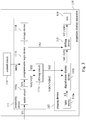
Fig. 1 is a function block diagram of a projection display apparatus according to an embodiment of the present disclosure. -
Fig. 2 is a system setting representation of a projection display apparatus according to an embodiment of the present disclosure. -
Fig. 3 is a partial circuit diagram of a projection display apparatus according to an embodiment of the present disclosure. -
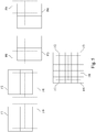
Fig. 4 is a schematic diagram of a converting method of an input video signal according to an embodiment of the present disclosure. -
Fig. 5 is a schematic diagram of a shifting method of a video image according to an embodiment of the present disclosure. -
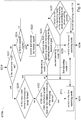
Fig. 6 is a flow chart of a control method according to an embodiment of the present disclosure. -
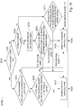
Fig. 7 is a flow chart of further steps included in step S220 in the control method ofFig. 6 according to some embodiments. -
Fig. 8 is a flow chart of further steps included in step S220 in the control method ofFig. 6 according to some embodiments. -
Fig. 9 is a flow chart of further steps included in step S220 in the control method ofFig. 6 according to some embodiments. -
Fig. 10 is a flow chart of further steps included in step S220 in the control method ofFig. 6 according to some embodiments. -
Fig. 11 is a flow chart of further steps included in step S220 in the control method ofFig. 6 according to some embodiments. -
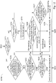
Fig. 12 is a flow chart of further steps included in step S220 in the control method ofFig. 6 according to some embodiments. - Although embodiments are described in detail with the accompanying drawings, they are not intended to limit the scope of the present disclosure. Moreover, the operation of the described structure does not limit the order of implementation. Any device with equivalent functions configured by different combinations of disclosed elements is intended to be covered by the scope of the present disclosure. Drawings are for the purpose of illustration only, and not plotted in accordance with the original size.
- It will be understood that when an element is referred to as being "connected to" or "coupled to", it can be directly connected or coupled to the other element or intervening elements may be present. In contrast, when an element to another element is referred to as being "directly connected" or "directly coupled," there are no intervening elements present. As used herein, the term "and / or" includes an associated listed items or any and all combinations of more.
- Referring to
Fig. 1 , aprojection display apparatus 110 is shown which includes aprocessing circuit 111, animaging device 112, acommunication device 113, acontrol circuit 114, ashifting device 115, and alens 116. Theprocessing circuit 111 is electrically coupled to theimaging device 112, thecontrol circuit 114 and theshifting device 115. Thecontrol circuit 114 is electrically coupled to theprocessing circuit 111, theimaging device 112, thecommunication device 113, theshifting device 115 and thelens 116. In an embodiment, theprocessing circuit 111 may be a processor such as a scaler, an image processor or FPGA. Thecommunication device 113 may be a component of various protocol interfaces (wired or wireless), a wireless communication chip, and/or other component with communication function for receiving a wearing signal of astereoscopic glasses 120 and transmitting the stereoscopic left/right eye synchronization signals to thestereoscopic glasses 120. Thecontrol circuit 114 may be a central processor or a microprocessor. The implementation and connection of the devices and components in theprojection display apparatus 110 are not limited to the above described, and any connection method and implementation method suitable for theprojection display apparatus 110 to implement the following technical contents can be applied to the present case. - Referring to
Fig. 1 andFig. 2 , aprojection display apparatus 110 is shown which includes afirst operating mode 117 and asecond operating mode 118. The operating modes may be set to a high resolution mode or a high frame rate mode. Theprojection display apparatus 110 further includes athrow ratio 119, which is generally defined as the projection distance divided by the width of the projected image for representing the length of the focal length of the projection lens, and the throw ratio can be manually set or automatically detected. The focal length of the projection lens can be changed by changing the lens, or be adjustable such as by manually adjusting the lens or electrically adjusting by the projection display apparatus 110 (e.g., controlled by the control circuit 114). When the focal length of the projection lens has been changed, thethrow ratio 119 of theprojection display apparatus 110 can be correspondingly updated. - In an embodiment, the
processing circuit 111 receives an input video signal VI1, and the input video signal VI1 includes an input video feature. The input video feature may include examples such as input video clocking and display timing information, input video resolution, input video format (e.g., stereoscopic image format) or compression indicator such as if it is in a compressed format, etc. In some embodiments, thecontrol circuit 114 selectively switches theprojection display apparatus 110 to thefirst operating mode 117 or thesecond operating mode 118 according to the input video feature or an operating condition of theprojection display apparatus 110. In another embodiment, thecontrol circuit 114 selectively switches theprojection display apparatus 110 to thefirst operating mode 117 or thesecond operating mode 118 according to a priority order set by the projection display apparatus 110 (e.g., shown inFig. 7 to Fig. 12 ). Theprojection display apparatus 110 can preferentially determine whether to switch to thefirst operating mode 117 or thesecond operating mode 118 according to the input video feature, or preferentially according to the operating condition, or according to the priority order set by theprojection display apparatus 110. A more detailed determination and selection process is described later. - In an embodiment, the
imaging device 112 may have a native resolution of 3840×2160, which is also referred to as 4K resolution. In some applications, the input video signal VI1 may provide an image resolution greater than the native resolution of theimaging device 112. For example, the input video signal VI1 may provide an input image of 8K (7680x4320) resolution. In general, when the resolution of the input image is greater than the native resolution of the imaging device, the projection display apparatus can only exhibit effect to the level of the native resolution. In an embodiment of the present disclosure, theprojection display apparatus 110 can switch to a particular operating mode according to the feature of the input video signal VI1 (e.g., resolution of the input video signal). - For example, when the
projection display apparatus 110 is switched to thefirst operating mode 117, theprocessing circuit 111 converts the input video signal VI1 to a first driving output video signal VDO1 which is input into theimaging device 112. Theimaging device 112 has a first display resolution (e.g., 4K, 3840x2160), and theimaging device 112 receives the first drive output video signal VDO1 and images the first output video image VF1 to the shiftingdevice 115. The shiftingdevice 115 cooperates with theimaging device 112 to cause aprojection image 130, having a second display resolution (e.g., 8K, 7680x4320) that is greater than the first display resolution (e.g., aforementioned 4K), to be projected onto ascreen 300. By this way, theprojection display apparatus 110 with a lower native resolution can be operated to present a higher-resolution-equivalent output image. A more detailed process is described later. - In some applications, the resolution of the input image may not be greater than the native resolution of the
projection display apparatus 110. In this circumstance, it is not necessary to increase the display resolution of theprojection display apparatus 110 to display the input image resolution. Also, in some applications, displaying a higher resolution image does not enhance the viewing experience, and therefore it is not desirable to increase the display resolution of theprojection display apparatus 110. For example, in an embodiment of the present disclosure, theprojection display apparatus 110 can determine to select a particular operating mode better suited for 3D viewing according to the feature of the input video signal VI1 (e.g., if the input video signal has a stereoscopic format). - The
projection display apparatus 110 can switch to thesecond operating mode 118, wherein theprocessing circuit 111 converts the input video signal VI1 to a second driving output video signal VDO2. Theimaging device 112 receives the second driving output video signal VDO2 and images the second output video image VF2 to the shiftingdevice 115. The shiftingdevice 115 does not engage, and the second output video image VF2 is directly projected onto thescreen 300 via thelens 116. - Referring to
Fig.3 , aprojection display apparatus 110 is shown which includes aprocessing circuit 111, acontrol circuit 114, animaging device 112, a shiftingdevice 115 andlens 116. Theprocessing circuit 111 includes ascaler circuit 111a, aprogrammable logic device 111b, a drivingcircuit 111c and astorage device 111d. Theimaging device 112 includes alight source 112a and a digitalmicro display device 112b. Thescaler circuit 111a adjusts the input image specifications to the image specifications of theprojection display apparatus 110. For example, thescaler circuit 111a can adjust a 4:3 or 16:10 projection aspect ratio input signal to a 16:9 projection aspect ratio of theprojection display apparatus 110. Thescaler circuit 111a adjusts the input video signal VI1 to generate an input video signal VI2. - According to an input video feature of the input video signal VI2 or an operating conditions of the
projection display apparatus 110, thecontrol circuit 114 transmits a mode switching signal MSS to theprogrammable logic device 111b. The mode switching signal MSS can be a signal indicating the selection of, and setting theprojection display apparatus 110 to, thefirst operating mode 117. After receiving the mode switching signal MSS, theprogrammable logic device 111b converts the input video signal VI2 and outputs the first output video signal VO1, a clock signal TS1 and another clock signal TS2. Theprogrammable logic device 111b transmits the clock signal TS1 to the shiftingdevice 115 and also transmits the clock signal TS2, which is another synchronized clock signal, to theimaging device 112 via thedriving circuit 111c. - The driving
circuit 111c converts the first output video signal VO1 to a first driving output video signal VDO1 and outputs it to the digitalmicro display device 112b. In this embodiment, the first output video signal VO1 sent by theprogrammable logic device 111b to thedriving circuit 111c may include image data such as color, brightness, and the like, of a plurality of pixels in each frame of a video stream (e.g., jpeg, bmp, gif, tiff or other picture or image storage format). The drivingcircuit 111c converts the first output video signal VO1 to a control signal format required by the digitalmicro display device 112b. In practical applications, the digitalmicro display device 112b includes a mirror matrix composed of a plurality of reflective mirrors, each of which can rotate at a very high speed, and the angle of rotation has two states, respectively representing the instantaneous brightness of each pixel in the picture. The ratio of bright time and dark time determines the brightness of each pixel in the picture. The driving output video signal VDO1 converted by the drivingcircuit 111c can be used to control the state and timing of rotation of the mirror. For example, if the ratio of bright time and dark time of the rotation state of one pixel is 50%-50%, the screen will be 50% brightness. That is, the first driving output video signal VDO1 processed by the drivingcircuit 111c can be used to drive the timing of the mirror matrix in the digitalmicro display device 112b to a desired rotation state. The digitalmicro display device 112b projects a display image to a projection optical path by the light LS emitted by alight source 112a and other optical components (not shown), and the display image on the digitalmicro display device 112b is projected onto thescreen 300 via the shiftingdevice 115 and thelens 116. - Referring to
Fig. 4 , in thefirst operating mode 117, theprogrammable logic device 111b converts the input video signal VI2 into a first output video signal VO1, and the first output video signal VO1 includes a first sub-image VO1a, a second sub-image VO1b, and a third sub-image VO1c and a fourth sub-image VO1d. Using a 4x4 example,Fig. 4 shows an exemplary conversion method in which the 16 pixel points of the input video signal VI2 are equally divided into four pixel regions such as an upper left pixel region, an upper right pixel region, a lower left pixel region and a lower right pixel region. The four pixel points of each pixel region are divided into four pixel blocks such as an upper left pixel block, an upper right pixel block, a lower left pixel block, and a lower right pixel block. The pixels of the same pixel block in the four pixel regions combine into a new sub-picture. In this embodiment, for convenience of description, the pixel points of the same pixel block are denoted by the same number, and the four pixel points of the first sub-image VO1a is composed of the upper left pixel block of the four areas of the first output video signal VO1 (numbered as 1); the second sub-image VO1b is composed of the upper right pixel block (numbered as 2); the third sub-image VO1c is composed of the lower right pixel block (numbered as 3); and the fourth sub-image VO1d is composed of the lower left pixel block (numbered as 4). - Using the abovementioned technology, the
projection display apparatus 110 realizes an image whose output resolution is greater than the native resolution of the projection device, by cooperation of the digitalmicro display component 112b and the shiftingdevice 115. - The
programmable logic device 111b may be a field programmable gate array (FPGA), a programmable array logic (PAL), a generic array logic (GAL), or a complex programmable logic device (CPLD), or any other equivalent programmable logic devices. The digitalmicro display device 112b may include a matrix of a plurality of micro mirrors and using a micro switch for adjusting the micro mirrors. - The shifting
device 115 is set up to operate cooperatively with the digitalmicro display device 112b. In an embodiment, the shiftingdevice 115 may include the mirrors with two sets of voice coil motors. One set of the voice coil motors may be set up to shift the projected image of the digitalmicro display device 112b in a first axial direction (for example, up and down along a vertical axis). Another set of the voice coil motors may be set up to shift the projection image of the digitalmicro display device 112b in a second axial direction (for example, left and right along a horizontal axis). The disclosure is not limited thereto, and the two sets of the voice coil motors are not limited to move along the vertical and horizontal axes, but may also move along other distinct axial directions, for example, along +45 degrees and -45 degrees. Further, the movement is not limited to biaxial, and may also be uniaxial to shift the projection image in one axial direction. In an embodiment, the shiftingdevice 115 may also include a set of voice coil motor for shifting the projected image of the digitalmicro display device 112b along a single axis. In an embodiment, the shiftingdevice 115 can include multiple sets of voice coil motors that shift the projected image of the digitalmicro display device 112b along different axes. - Referring to
Figs. 3-5 ,Fig. 3 shows a clock signal TS2 for controlling the switching of theprojection image 130 of the digitalmicro display device 112b and a clock signal TS1 for controlling the shifting direction of the shiftingdevice 115.Fig. 5 shows an original image F0 being the original image of the first output video signal VO1. As shown in theFig. 3 , theprogrammable logic device 111b transmits two synchronized signals, clock signals TS1 and TS2, to the shiftingdevice 115 and the digitalmicro display device 112b in theimaging device 112, respectively. In this way, the shiftingdevice 115 and the digitalmicro display device 112b can together control the display of the image according to the synchronized signals, clock signals TS1 and TS2. When the image displayed by the digitalmicro display device 112b is switched between the first sub-image VO1a, the second sub-image VO1b, the third sub-image VO1c, and the fourth sub-image VO1d, the shiftingdevice 115 can synchronously move the image projected by the digitalmicro display device 112b to the upper left, upper right, lower right, and lower left, as shown inFig. 5 . - For example, at the first time the
programmable logic device 111b controls the shiftingdevice 115 to bi-axially shift to an upper left position. Theprogrammable logic device 111b transmits the clock signal TS1 to the shiftingdevice 115 to drive the shiftingdevice 115 to perform the above operation. The shiftingdevice 115 may include two bi-axial voice coil motors, one of which shifts the projected image of the digitalmicro display device 112b to the left by 1/4 pixel width, and another one simultaneously shifts the projected image of the digitalmicro display device 112b upward by 1/4 pixel width. According to the driving of the clock signal TS2, the first sub-image VO1a is imaged on the digitalmicro display device 112b, and the light LS projected by thelight source 112a causes a first position image F1 to form through the digitalmicro display device 112b. In this embodiment, the clock signal TS1 which controls the shiftingdevice 115 and the clock signal TS2 which controls the digitalmicro display device 112b are synchronized with each other to drive the shiftingdevice 115 and the digitalmicro display device 112b at the same time. - Next, at the second time, according to the clock signal TS1 transmitted by the
programmable logic device 111b to the shiftingdevice 115, the shiftingdevice 115 is controlled to bi-axially shift to an upper right position. At this time, the digitalmicro display device 112b, which receives the clock signal TS2 synchronized with the clock signal TS1, changes the imaged content from the first sub-image VO1a to the second sub-image VO1b according to the clock signal TS2. The light LS projected by thelight source 112a causes a second position image F2 to form through the digitalmicro display device 112b. By synchronization of the clock signals TS1 and TS2, the shifting of the shiftingdevice 115 and the imaging content of the digitalmicro display device 112b are simultaneously actioned. - At the third time, according to the clock signal TS1 transmitted by the
programmable logic device 111b to the shiftingdevice 115, the shiftingdevice 115 is controlled to bi-axially shift to a lower right position. At this time, the digitalmicro display device 112b, which receives the clock signal TS2 synchronized with the clock signal TS1, changes the imaged content from the second sub-image VO1b to the third sub-image VO1c according to the driving of the clock signal TS2. The light LS projected by thelight source 112a causes the third position image F3 to form through the digitalmicro display device 112b. - At the fourth time, according to the clock signal TS1 transmitted by the
programmable logic device 111b to the shiftingdevice 115, the shiftingdevice 115 is controlled to bi-axially shift to a lower left position. Similar to the above described operation, at this time, the light LS projected by thelight source 112a causes a fourth position image F4 to form through the digitalmicro display device 112b. - The first position image F1, the second position image F2, the third position image F3 and the fourth position image F4 partially overlap with each other as shown in
Fig. 5 . The four images overlap to become a first output video image VF1 for displaying on ascreen 300 through thelens 116. When the frequency of the shift as described above is greater than the time that human eyes can react, the displayed image is perceived as having a higher resolution than the original image F0. - Returning to
Fig. 3 , according to an example embodiment, when theprogrammable logic device 111b receives the mode switching signal MSS having indications for setting theprojection display apparatus 110 to thesecond operating mode 118, the shiftingdevice 115 does not start the above described shifting process. Theprogrammable logic device 111b accesses data for the image to be displayed by using thestorage device 111d to obtain a second output video signal VO2 and to obtain a frame rate greater than the input video signal VI2. The second output video signal VO2 is imaged as the second output video image VF2 via the digitalmicro display device 112b for displaying on ascreen 300 through thelens 116. Accordingly, the projection frame rate of the plurality of the second output video images VF2 is greater than the frame rate of the input video signal VI2. In an embodiment, thestorage device 111d may be a frame buffer used to temporarily store the image data. Through reading and writing of the frame buffer, the images to be displayed are arranged for output to achieve a high frame rate projection display. - In other words, according to embodiments of the present disclosure, the
first operating mode 117 is set to a high resolution mode, and thesecond operating mode 118 is set to a high frame rate mode. -
Figs. 6 to 12 show flow charts of control methods according to embodiments of the present disclosure. Referring toFig. 6 , forcontrol method 200, at step S210, an input video signal is received, and step S220 determines to switch to thefirst operating mode 117 or thesecond operating mode 118 according to an input video feature or an operating condition of theprojection display apparatus 110. If switching to thefirst operating mode 117, then the process goes to step S230. At step S230, an input video signal VI2 is converted and output as a first output video signal VO1. Next, at step S240, the first output video signal VO1 is received and a plurality of first output video images VF1 is output. If switching to thesecond operating mode 118, the process goes to step S250. At step S250, an input video signal VI2 is converted and output as a second output video signal VO2. Next, at step S260, the second output video signal VO2 is received and a plurality of second output video images VF2 is output. According to embodiments of the present disclosure, thefirst operating mode 117 may be set to a high resolution mode and thesecond operating mode 118 may be set to a high frame rate mode. Examples of determination method are described below. -
Fig. 7 to Fig. 12 show steps S220a to S220f as different embodiments of the determination step S220 inFig. 6 . - Referring to the embodiment shown in
Fig. 7 , following step S210, step S221 determines if an automatic mode is enabled, and if yes, then proceed to step S222. At step S222, if the resolution of the input video is greater than the display resolution (first display resolution) of theimaging device 112 of theprojection display apparatus 110 is determined, then the image to be viewed can be regarded as a high-resolution image. Since theprojection display apparatus 110 would need to support an increased resolution, the process goes to step S223 to switch theprojection display apparatus 110 to a first operating mode 117 (high resolution mode). If the resolution of the input video is not greater than the display resolution of theimaging device 112, then the process proceeds to step S228 which switches theprojection display apparatus 110 to a second operating mode 118 (high frame rate mode). Referring back to the determination step S221, if the automatic mode is not on, then proceed to step S224 which determines if there is a manual signal indicating which operating mode to select. The presence of a manual control signal likely means that a user wants to assert a manual control. If there is no manual signal, the process proceeds to step S227 which theprojection display apparatus 110 is switched to thefirst operating mode 117 or thesecond operating mode 118 according to the projection display apparatus' preset system setting. If there is a manual signal at step S224, then at step S225, theprojection display apparatus 110 receives and processes the manual signal. At step S226, according to the received manual signal, a determination is made to switch to the first operating mode 117 (step S223) or to the second operating mode 118 (step S228). - Referring to the embodiment shown in
Fig. 8 , step S221 determines if an automatic mode is enabled, and if yes, then proceed to step S229 to detect if the input video format is a stereoscopic image format according to an indication of the stereoscopic image information. In an embodiment, the stereoscopic image information includes an indication of input video format including left-eye image frames and right-eye image frames. Since an input video signal having stereoscopic image information will match with a corresponding stereoscopic glasses to enable a viewer's left and right eyes to sequentially receive images of a certain frequency (for example, 60 Hz for each of the left and right eyes images), this feature of the input video signal can be used to determine if the input video format is a stereoscopic image format. Viewing stereoscopic images has less need for displaying images in high resolution. Accordingly, if it is determined that the input video format is stereoscopic image format, the process proceeds to step S228 which switches theprojection display apparatus 110 to thesecond operating mode 118. If the input video format is not in stereoscopic image format, the process proceeds to step S222 to determine if the resolution of the input video is greater than the first display resolution of theimaging device 112. This determination step and other manual mode steps are as same as the above described with reference toFig. 7 , and are not repeat herein. - Referring to the embodiment shown in
Fig. 9 , step S221 determines if an automatic mode is enabled, and if yes, then proceed to step S230 to determine if the input video format is a compressed format. This determination can take into consideration one or more video compression rate parameter, such as compression ratio, compression type, and compression encryption. In general, the resolution of an image after compression is lower than its resolution before compression. Since a user that compresses an image usually utilizes it for the convenience of data transmission or convenience of use, it less likely that high image resolution is of concern. Accordingly, if the input video format is determined to be a compressed format, it is assumed that the first operating mode 117 (high resolution mode) is not applicable, and therefore the process proceeds to step S228 which switches theprojection display apparatus 110 to thesecond operating mode 118. If the input video format is determined not to be a compressed format, the process proceeds to step S222 to determine if the resolution of the input video is greater than the first display resolution of theimaging device 112. This determination step and the other steps shown in theFig. 9 are the same as previously described, and are not repeated herein. - Referring to the embodiment shown in
Fig. 10 , step S221 determines if an automatic mode is enabled, and if yes, then proceed to step S231. When a user wears thestereoscopic glasses 120 for viewing images displayed by theprojection display apparatus 110, thecommunication device 113 receives a wearing signal of thestereoscopic glasses 120 and transmits a stereoscopic left/right eye synchronization signal to thestereoscopic glasses 120. Step S231 detects if the stereoscopic left/right eye synchronization signal is active, and if yes, proceed to step S228. Similar to previously described determination step S230 ofFig. 8 , if there is an indication that the stereoscopic image is to be viewed, so that it is assumed that the first operating mode 117 (high resolution mode) is not applicable, and the process proceed to S228 which switches theprojection display apparatus 110 to thesecond operating mode 118. If it is determined that the stereoscopic left/right eye synchronization signal from thecommunication device 113 has been transmitted, the process proceed to step S222 to determine if the resolution of the input video is greater than the first display resolution of theimaging device 112. This determination step and the other steps shown in theFig. 10 are the same as previously described, and are not repeated here. - Referring to the embodiment shown in
Fig. 11 , step S221 determines if an automatic mode is enabled, and if yes, then proceed to step S222 to determine if the resolution of the input video is greater than the first display resolution of theimaging device 112. If the resolution of the input video is determined to be greater than the first display resolution of theimaging device 112, proceed to step S232 which determines if athrow ratio 119 of theprojection display apparatus 110 is smaller than a preset throw ratio value. Throwratio 119 is defined as a ratio (D/W), which is the distance (D) between thelens 116 and thescreen 300, divided by the width (W) of theprojection image 130. As previously described with reference toFig.1 andFig. 2 , thethrow ratio 119 of theprojection display apparatus 110 can be changed (e.g., by changing thelens 116, manually adjusted, or electrically adjusted). Accordingly, with different use of theprojection display apparatus 110, itsthrow ratio 119 may be set differently compared to other uses. Comparatively, the preset throw ratio value of theprojection display apparatus 110 is a fixed setting which when used for determination (further described herein), provides a threshold-type parameter for use to switch the operating modes of theprojection display apparatus 110. - At step S232, if the
throw ratio 119 is determined to be smaller than the preset throw ratio value, then proceed to step S223 to switch to thefirst operating mode 117. A small throw ratio may mean that theprojection display apparatus 110 is using short focal length lens (for projecting a larger image over a relatively short distance). In this situation, a higher resolution may be desired, and therefore by switching theprojection display apparatus 110 to the first operating mode 117 (high resolution mode), enhanced resolution images can be projected for viewing. Conversely, a larger throw ratio is likely to mean that high resolution is not required. Therefore, by comparing theprojection display apparatus 110 throw ratio to a preset throw ratio value, a determination can be made as to which of the first operating mode 117 (high resolution mode) or the second operating mode 118 (high frame mode) is more suitable for use. For example, a setting could be made such that if thethrow ratio 119 of theprojection display apparatus 110 is not lower than the preset throw ratio value, step S228 proceeds to switch to thesecond operating mode 118. The other steps shown in theFig. 11 are the same as previously described, and are not repeated herein. - Referring to the embodiment shown in
Fig. 12 , step S221 determines if an automatic mode is enabled, and if yes, then proceed to step S233. At step S233, the input video feature and the operating condition previously described are assessed, including determining if the input video format is a stereoscopic image format or a compressed format, or if thestereoscopic glasses 120 has been worn (e.g. if the stereoscopic left/right eye synchronization signal is active). If any of these determinations is a "yes", then proceed to step S228 which switches theprojection display apparatus 110 to thesecond operating mode 118. If all three determination results are "no", then proceed to step S222 to determine if the input video resolution is greater than the first display resolution of theimaging device 112. If the determination result is a "no", then proceed to step S228 to switch theprojection display apparatus 110 to thesecond operating mode 118. If the determination result is a "yes", then proceed to step S232 to determine if thethrow ratio 119 of theprojection display apparatus 110 is smaller than a preset throw ratio value. If the determination result is a "yes" (i.e., thethrow ratio 119 is smaller than the preset throw ratio value), then proceed to step S223 to switch theprojection display apparatus 110 to thefirst operating mode 117. If determination result is a "no" (i.e., thethrow ratio 119 is greater than the preset throw ratio value), then proceed to step S228 to switch theprojection display apparatus 110 to thesecond operating mode 118. The other steps shown in theFig. 12 are the same as previously described, and are not repeated herein. - The control method of the present disclosure that can be implemented is not limited to the above examples. The
projection display apparatus 110 may determine to switch to thefirst operating mode 117 or thesecond operating mode 118 preferentially according to the input video feature or preferentially according to one or more operating conditions. Other than initial apparatus settings, a user can also set/change the priority order of which theprojection display apparatus 110 undertakes determination to the switch to thefirst operating mode 117 or thesecond operating mode 118, according to various input video features and operating conditions.
Claims (15)
- A projection display apparatus (110), characterized by:a first operating mode (117) and a second operating mode (118), configured to operate the projection display apparatus (110) in an operating condition;a processing circuit (111), configured to receive an input video signal (VI1), wherein the input video signal (VI1) comprises an input video feature, wherein in the first operating mode (117), the processing circuit (111) converts the input video signal (VI1) and outputs a first output video signal (VDO1), and wherein in the second operating mode (118), the processing circuit (111) converts the input video signal (VI1) and outputs a second output video signal (VDO2);a control circuit (114) coupled to the processing circuit (111), wherein the control circuit (114) is configured to selectively switch the projection display apparatus (110) to the first operating mode (117) or the second operating mode (118) according to the input video feature or the operating condition;an imaging device (112), configured to receive the first output video signal (VDO1) and output a plurality of first output video images (VF1) corresponding to the first output video signal (VDO1), the imaging device (112) is further configured to receive the second output video signal (VDO2) and output a plurality of second output video images (VF2) corresponding to the second output video signal (VDO2), wherein the imaging device (112) comprises a first display resolution; anda shifting device (115), coupled to the imaging device (112), wherein in the first operating mode (117), the shifting device (115) cooperates with the imaging device (112) to effect a projection of a projection image (130) to a screen (300), wherein the projection image (130) comprises a second display resolution greater than the first display resolution.
- The projection display apparatus (110) of claim 1, characterized in that the first operating mode (117) is a high resolution mode, and the second operating mode (118) is a high frame rate mode.
- The projection display apparatus (110) of claim 2, characterized in that in the high frame rate mode, the processing circuit (111) cooperates with the imaging device (112) to increase a projection frame rate of the plurality of second output video images (VF2), wherein the plurality of second output video images (VF2) comprise the first display resolution.
- The projection display apparatus (110) of claim 2, characterized in that in the high resolution mode, the shifting device (115) shifts the plurality of first output video images (VF1) in a uniaxial or biaxial direction to project the plurality of first output video images (VF1) which have been shifted as the projection image (130) comprising a display resolution equivalent to the second display resolution.
- The projection display apparatus (110) of claim 3, characterized in that the input video feature comprises an input video resolution, wherein:if the input video resolution is greater than the first display resolution, the control circuit (114) switches the projection display apparatus (110) to the high resolution mode; andif the input video resolution is not greater than the first display resolution, the control circuit (114) switches the projection display apparatus (110) to the high frame rate mode.
- The projection display apparatus (110) according to any one of claims 1-4, characterized in that the input video feature comprises:a stereoscopic image information comprising an indication of input video format including left-eye image frames and right-eye image frames; or a compression indicator comprising a video compression rate parameter,wherein the control circuit (114) is configured to switch the projection display apparatus (110) to the second operating mode (118) according to at least one of the stereoscopic image information and the compression indicator.
- The projection display apparatus (110) according to any one of claims 1-4 and claim 6, further characterized by:
a communication device (113), configured to couple to a stereoscopic glasses (120), wherein the operating condition comprises the communication device (113) transmitting a stereoscopic left/right eye synchronization signal to the stereoscopic glasses (120), and wherein the control circuit (114) switches the projection display apparatus (110) to the second operating mode (118) if the stereoscopic left/right eye synchronization signal is active. - The projection display apparatus (110) according to any one of claims 1-4, further characterized by:
an adjustable lens (116), wherein the operating condition comprises the projection display apparatus (110) projecting an image according to a throw ratio (119) corresponding to the adjustable lens (116), and wherein the control circuit (114) switches the projection display apparatus (110) to the first operating mode (117) if the throw ratio (119) is smaller than or equal to a preset throw ratio value. - A method (200) for controlling a projection display apparatus (110), characterized by:receiving, by a processing circuit (111), an input video signal (VI1) comprising an input video feature;selectively switching the projection display apparatus (110), by a control circuit (114), to a first operating mode (117) or a second operating mode (118) according to the input video feature or an operating condition of the projection display apparatus (110),wherein if switched to the first operating mode (117):converting, by the processing circuit (111), the input video signal (VI1) and outputting a first output video signal (VDO1);receiving, by an imaging device (112), the first output video signal (VDO1) and outputting a plurality of first output video images (VF1) corresponding to the first output video signal (VDO1), wherein the imaging device (112) comprises a first display resolution;shifting, by a shifting device (115) cooperating with the imaging device (112), the plurality of first output video images (VF1); andprojecting, to a screen (300), a projection image (130) corresponding to the plurality of first output video images (VF1), wherein the projection image (130) comprises a second display resolution greater than the first display resolution,and wherein if switched to the second operating mode (118):converting, by the processing circuit (111), the input video signal (VI1) and outputting a second output video signal (VDO2);receiving, by an imaging device (112), the second output video signal (VDO2) and outputting a plurality of second output video images (VF2) corresponding to the second output video signal (VDO2).
- The method (200) of claim 9, characterized in that the first operating mode (117) is a high resolution mode, and the second operating mode (118) is a high frame rate mode, wherein the method (200) further comprises:
if switched to the high frame rate mode:
increasing, by the processing circuit (111) cooperating with the imaging device (112), a projection frame rate of the plurality of second output video images (VF2), wherein the plurality of second output video images (VF2) comprise the first display resolution. - The method (200) of claim 9 or claim 10, characterized in that the operating condition comprises an automatic mode and a manual control, wherein the method (200) further comprises:determining, by the processing circuit (111), if the automatic mode is enabled;determining, by the processing circuit (111), if a manual control signal corresponding to the manual control is received; andif the manual control signal is received, switching the projection display apparatus (110), by the control circuit (114), to the first operating mode (117) or the second operating mode (118) according to the manual control signal, andif the automatic mode is not enabled and the manual control signal is not received, switching the projection display apparatus (110), by the control circuit (114), to the first operating mode (117) or the second operating mode (118) according to a preset system setting of the projection display apparatus (110).
- The method (200) of claim 10, characterized in that the method (200) further comprises:
if switched to the high resolution mode:
shifting, by the shifting device (115) cooperating with the imaging device (112), the plurality of first output video images (VF1) in a uniaxial or biaxial direction to project the plurality of first output video images (VF1) which have been shifted as the projection images (130) comprising a display resolution equivalent to the second display resolution. - The method (200) of claim 10, characterized in that the input video feature comprises an input video resolution, and the method (200) further comprises:determining, by the processing circuit (111), if the input video resolution is greater than the first display resolution, and if yes, switching the projection display apparatus (110), by the control circuit (114), to the high resolution mode; anddetermining, by the processing circuit (111), if the input video resolution is equal to or smaller than the first display resolution, and if yes, switching the projection display apparatus (110), by the control circuit (114), to the high frame rate mode.
- The method (200) of claims 9, 10 or 12, further characterized by:
determining, by the processing circuit (111), if the input video feature comprises a stereoscopic image information, and if yes, switching the projection display apparatus (110), by the control circuit (114), to the second operating mode (118), wherein the stereoscopic image information comprises an indication of input video format including left-eye image frames and right-eye image frames. - The method (200) of claims 9, 10, 12 or 14, further characterized by:
determining, by the processing circuit (111), if the input video feature comprises a compression indicator, and if yes, switching the projection display apparatus (110), by the control circuit (114), to the second operating mode (118), wherein the compression indicator comprises a video compression rate parameter.
Applications Claiming Priority (1)
| Application Number | Priority Date | Filing Date | Title |
|---|---|---|---|
| CN201811375974.2A CN110312109B (en) | 2018-03-20 | 2018-11-19 | Projection display apparatus and control method |
Publications (3)
| Publication Number | Publication Date |
|---|---|
| EP3654642A1 true EP3654642A1 (en) | 2020-05-20 |
| EP3654642B1 EP3654642B1 (en) | 2023-10-18 |
| EP3654642C0 EP3654642C0 (en) | 2023-10-18 |
Family
ID=67105938
Family Applications (1)
| Application Number | Title | Priority Date | Filing Date |
|---|---|---|---|
| EP19182999.3A Active EP3654642B1 (en) | 2018-11-19 | 2019-06-27 | Projection display apparatus and method for controlling the same |
Country Status (3)
| Country | Link |
|---|---|
| EP (1) | EP3654642B1 (en) |
| ES (1) | ES2966089T3 (en) |
| PL (1) | PL3654642T3 (en) |
Citations (3)
| Publication number | Priority date | Publication date | Assignee | Title |
|---|---|---|---|---|
| US20140285483A1 (en) * | 2013-03-25 | 2014-09-25 | Sony Corporation | Image processing apparatus, image processing method, and program |
| US20140293247A1 (en) * | 2013-03-27 | 2014-10-02 | Panasonic Corporation | Projection display apparatus |
| CN108696732A (en) * | 2017-02-17 | 2018-10-23 | 北京三星通信技术研究有限公司 | Wear the method for adjusting resolution and equipment of display equipment |
-
2019
- 2019-06-27 PL PL19182999.3T patent/PL3654642T3/en unknown
- 2019-06-27 EP EP19182999.3A patent/EP3654642B1/en active Active
- 2019-06-27 ES ES19182999T patent/ES2966089T3/en active Active
Patent Citations (3)
| Publication number | Priority date | Publication date | Assignee | Title |
|---|---|---|---|---|
| US20140285483A1 (en) * | 2013-03-25 | 2014-09-25 | Sony Corporation | Image processing apparatus, image processing method, and program |
| US20140293247A1 (en) * | 2013-03-27 | 2014-10-02 | Panasonic Corporation | Projection display apparatus |
| CN108696732A (en) * | 2017-02-17 | 2018-10-23 | 北京三星通信技术研究有限公司 | Wear the method for adjusting resolution and equipment of display equipment |
Also Published As
| Publication number | Publication date |
|---|---|
| EP3654642B1 (en) | 2023-10-18 |
| EP3654642C0 (en) | 2023-10-18 |
| PL3654642T3 (en) | 2024-03-18 |
| ES2966089T3 (en) | 2024-04-18 |
Similar Documents
| Publication | Publication Date | Title |
|---|---|---|
| US10798354B2 (en) | Projection display apparatus and method for controlling the same | |
| US20080151040A1 (en) | Three-dimensional image display apparatus and method and system for processing three-dimensional image signal | |
| KR101626742B1 (en) | System for Displaying Multi Video | |
| US20090051759A1 (en) | Equipment and methods for the synchronization of stereoscopic projection displays | |
| US8896676B2 (en) | Method and system for determining transmittance intervals in 3D shutter eyewear based on display panel response time | |
| US9438896B2 (en) | Method for driving 3D binocular eyewear from standard video stream | |
| US20110063422A1 (en) | Video processing system and video processing method | |
| JP4827783B2 (en) | Image display device | |
| US8854438B2 (en) | Display system, display apparatus and control method thereof | |
| US20120026304A1 (en) | Stereoscopic video output device and backlight control method | |
| CN104038685A (en) | Imaging Device And Image Processing Method | |
| US9967540B2 (en) | Ultra high definition 3D conversion device and an ultra high definition 3D display system | |
| JP2018093305A (en) | Display device, control method for the same, program, and storage medium | |
| US9392250B2 (en) | Imaging apparatus and control method therefor | |
| US20120002009A1 (en) | Video signal processing apparatus and video signal processing method | |
| EP3654642B1 (en) | Projection display apparatus and method for controlling the same | |
| US20110181745A1 (en) | Presentation system | |
| CN218719816U (en) | Projector and projection apparatus | |
| US8274604B2 (en) | Image display unit | |
| JPH0715646A (en) | Network compatible camera | |
| TWI899854B (en) | Projection display device | |
| US20120081526A1 (en) | Image display method and image display system for increasing horizontal blanking interval data to generate adjusted horizontal blanking interval data | |
| US12513267B2 (en) | Projection display device | |
| JP2014027351A (en) | Image processing device, image processing method, and program | |
| JP7267713B2 (en) | PROJECTION DEVICE, CONTROL METHOD THEREOF, AND PROGRAM |
Legal Events
| Date | Code | Title | Description |
|---|---|---|---|
| PUAI | Public reference made under article 153(3) epc to a published international application that has entered the european phase |
Free format text: ORIGINAL CODE: 0009012 |
|
| STAA | Information on the status of an ep patent application or granted ep patent |
Free format text: STATUS: THE APPLICATION HAS BEEN PUBLISHED |
|
| AK | Designated contracting states |
Kind code of ref document: A1 Designated state(s): AL AT BE BG CH CY CZ DE DK EE ES FI FR GB GR HR HU IE IS IT LI LT LU LV MC MK MT NL NO PL PT RO RS SE SI SK SM TR |
|
| AX | Request for extension of the european patent |
Extension state: BA ME |
|
| STAA | Information on the status of an ep patent application or granted ep patent |
Free format text: STATUS: REQUEST FOR EXAMINATION WAS MADE |
|
| 17P | Request for examination filed |
Effective date: 20201110 |
|
| RBV | Designated contracting states (corrected) |
Designated state(s): AL AT BE BG CH CY CZ DE DK EE ES FI FR GB GR HR HU IE IS IT LI LT LU LV MC MK MT NL NO PL PT RO RS SE SI SK SM TR |
|
| STAA | Information on the status of an ep patent application or granted ep patent |
Free format text: STATUS: EXAMINATION IS IN PROGRESS |
|
| 17Q | First examination report despatched |
Effective date: 20211130 |
|
| GRAP | Despatch of communication of intention to grant a patent |
Free format text: ORIGINAL CODE: EPIDOSNIGR1 |
|
| STAA | Information on the status of an ep patent application or granted ep patent |
Free format text: STATUS: GRANT OF PATENT IS INTENDED |
|
| INTG | Intention to grant announced |
Effective date: 20230619 |
|
| GRAS | Grant fee paid |
Free format text: ORIGINAL CODE: EPIDOSNIGR3 |
|
| GRAA | (expected) grant |
Free format text: ORIGINAL CODE: 0009210 |
|
| STAA | Information on the status of an ep patent application or granted ep patent |
Free format text: STATUS: THE PATENT HAS BEEN GRANTED |
|
| AK | Designated contracting states |
Kind code of ref document: B1 Designated state(s): AL AT BE BG CH CY CZ DE DK EE ES FI FR GB GR HR HU IE IS IT LI LT LU LV MC MK MT NL NO PL PT RO RS SE SI SK SM TR |
|
| REG | Reference to a national code |
Ref country code: GB Ref legal event code: FG4D |
|
| REG | Reference to a national code |
Ref country code: CH Ref legal event code: EP |
|
| REG | Reference to a national code |
Ref country code: IE Ref legal event code: FG4D |
|
| REG | Reference to a national code |
Ref country code: DE Ref legal event code: R096 Ref document number: 602019039475 Country of ref document: DE |
|
| U01 | Request for unitary effect filed |
Effective date: 20231108 |
|
| U07 | Unitary effect registered |
Designated state(s): AT BE BG DE DK EE FI FR IT LT LU LV MT NL PT SE SI Effective date: 20231113 |
|
| PG25 | Lapsed in a contracting state [announced via postgrant information from national office to epo] |
Ref country code: GR Free format text: LAPSE BECAUSE OF FAILURE TO SUBMIT A TRANSLATION OF THE DESCRIPTION OR TO PAY THE FEE WITHIN THE PRESCRIBED TIME-LIMIT Effective date: 20240119 |
|
| PG25 | Lapsed in a contracting state [announced via postgrant information from national office to epo] |
Ref country code: IS Free format text: LAPSE BECAUSE OF FAILURE TO SUBMIT A TRANSLATION OF THE DESCRIPTION OR TO PAY THE FEE WITHIN THE PRESCRIBED TIME-LIMIT Effective date: 20240218 |
|
| REG | Reference to a national code |
Ref country code: ES Ref legal event code: FG2A Ref document number: 2966089 Country of ref document: ES Kind code of ref document: T3 Effective date: 20240418 |
|
| PG25 | Lapsed in a contracting state [announced via postgrant information from national office to epo] |
Ref country code: IS Free format text: LAPSE BECAUSE OF FAILURE TO SUBMIT A TRANSLATION OF THE DESCRIPTION OR TO PAY THE FEE WITHIN THE PRESCRIBED TIME-LIMIT Effective date: 20240218 Ref country code: GR Free format text: LAPSE BECAUSE OF FAILURE TO SUBMIT A TRANSLATION OF THE DESCRIPTION OR TO PAY THE FEE WITHIN THE PRESCRIBED TIME-LIMIT Effective date: 20240119 |
|
| PG25 | Lapsed in a contracting state [announced via postgrant information from national office to epo] |
Ref country code: RS Free format text: LAPSE BECAUSE OF FAILURE TO SUBMIT A TRANSLATION OF THE DESCRIPTION OR TO PAY THE FEE WITHIN THE PRESCRIBED TIME-LIMIT Effective date: 20231018 Ref country code: NO Free format text: LAPSE BECAUSE OF FAILURE TO SUBMIT A TRANSLATION OF THE DESCRIPTION OR TO PAY THE FEE WITHIN THE PRESCRIBED TIME-LIMIT Effective date: 20240118 Ref country code: HR Free format text: LAPSE BECAUSE OF FAILURE TO SUBMIT A TRANSLATION OF THE DESCRIPTION OR TO PAY THE FEE WITHIN THE PRESCRIBED TIME-LIMIT Effective date: 20231018 |
|
| U20 | Renewal fee for the european patent with unitary effect paid |
Year of fee payment: 6 Effective date: 20240509 |
|
| REG | Reference to a national code |
Ref country code: DE Ref legal event code: R097 Ref document number: 602019039475 Country of ref document: DE |
|
| PG25 | Lapsed in a contracting state [announced via postgrant information from national office to epo] |
Ref country code: CZ Free format text: LAPSE BECAUSE OF FAILURE TO SUBMIT A TRANSLATION OF THE DESCRIPTION OR TO PAY THE FEE WITHIN THE PRESCRIBED TIME-LIMIT Effective date: 20231018 |
|
| PG25 | Lapsed in a contracting state [announced via postgrant information from national office to epo] |
Ref country code: SK Free format text: LAPSE BECAUSE OF FAILURE TO SUBMIT A TRANSLATION OF THE DESCRIPTION OR TO PAY THE FEE WITHIN THE PRESCRIBED TIME-LIMIT Effective date: 20231018 |
|
| PG25 | Lapsed in a contracting state [announced via postgrant information from national office to epo] |
Ref country code: SM Free format text: LAPSE BECAUSE OF FAILURE TO SUBMIT A TRANSLATION OF THE DESCRIPTION OR TO PAY THE FEE WITHIN THE PRESCRIBED TIME-LIMIT Effective date: 20231018 Ref country code: SK Free format text: LAPSE BECAUSE OF FAILURE TO SUBMIT A TRANSLATION OF THE DESCRIPTION OR TO PAY THE FEE WITHIN THE PRESCRIBED TIME-LIMIT Effective date: 20231018 Ref country code: RO Free format text: LAPSE BECAUSE OF FAILURE TO SUBMIT A TRANSLATION OF THE DESCRIPTION OR TO PAY THE FEE WITHIN THE PRESCRIBED TIME-LIMIT Effective date: 20231018 Ref country code: CZ Free format text: LAPSE BECAUSE OF FAILURE TO SUBMIT A TRANSLATION OF THE DESCRIPTION OR TO PAY THE FEE WITHIN THE PRESCRIBED TIME-LIMIT Effective date: 20231018 |
|
| PLBE | No opposition filed within time limit |
Free format text: ORIGINAL CODE: 0009261 |
|
| STAA | Information on the status of an ep patent application or granted ep patent |
Free format text: STATUS: NO OPPOSITION FILED WITHIN TIME LIMIT |
|
| 26N | No opposition filed |
Effective date: 20240719 |
|
| PG25 | Lapsed in a contracting state [announced via postgrant information from national office to epo] |
Ref country code: MC Free format text: LAPSE BECAUSE OF FAILURE TO SUBMIT A TRANSLATION OF THE DESCRIPTION OR TO PAY THE FEE WITHIN THE PRESCRIBED TIME-LIMIT Effective date: 20231018 |
|
| REG | Reference to a national code |
Ref country code: CH Ref legal event code: PL |
|
| PG25 | Lapsed in a contracting state [announced via postgrant information from national office to epo] |
Ref country code: IE Free format text: LAPSE BECAUSE OF NON-PAYMENT OF DUE FEES Effective date: 20240627 |
|
| PG25 | Lapsed in a contracting state [announced via postgrant information from national office to epo] |
Ref country code: CH Free format text: LAPSE BECAUSE OF NON-PAYMENT OF DUE FEES Effective date: 20240630 |
|
| U20 | Renewal fee for the european patent with unitary effect paid |
Year of fee payment: 7 Effective date: 20250509 |
|
| PGFP | Annual fee paid to national office [announced via postgrant information from national office to epo] |
Ref country code: PL Payment date: 20250424 Year of fee payment: 7 |
|
| PGFP | Annual fee paid to national office [announced via postgrant information from national office to epo] |
Ref country code: GB Payment date: 20250401 Year of fee payment: 7 |
|
| PGFP | Annual fee paid to national office [announced via postgrant information from national office to epo] |
Ref country code: TR Payment date: 20250620 Year of fee payment: 7 |
|
| PGFP | Annual fee paid to national office [announced via postgrant information from national office to epo] |
Ref country code: ES Payment date: 20250703 Year of fee payment: 7 |
|
| PG25 | Lapsed in a contracting state [announced via postgrant information from national office to epo] |
Ref country code: CY Free format text: LAPSE BECAUSE OF FAILURE TO SUBMIT A TRANSLATION OF THE DESCRIPTION OR TO PAY THE FEE WITHIN THE PRESCRIBED TIME-LIMIT; INVALID AB INITIO Effective date: 20190627 |
|
| PG25 | Lapsed in a contracting state [announced via postgrant information from national office to epo] |
Ref country code: HU Free format text: LAPSE BECAUSE OF FAILURE TO SUBMIT A TRANSLATION OF THE DESCRIPTION OR TO PAY THE FEE WITHIN THE PRESCRIBED TIME-LIMIT; INVALID AB INITIO Effective date: 20190627 |