EP3654491B1 - Wireless power transmission apparatus - Google Patents
Wireless power transmission apparatus Download PDFInfo
- Publication number
- EP3654491B1 EP3654491B1 EP19209824.2A EP19209824A EP3654491B1 EP 3654491 B1 EP3654491 B1 EP 3654491B1 EP 19209824 A EP19209824 A EP 19209824A EP 3654491 B1 EP3654491 B1 EP 3654491B1
- Authority
- EP
- European Patent Office
- Prior art keywords
- wireless power
- coils
- power transmission
- quality factor
- variation
- Prior art date
- Legal status (The legal status is an assumption and is not a legal conclusion. Google has not performed a legal analysis and makes no representation as to the accuracy of the status listed.)
- Active
Links
Images





Classifications
-
- H—ELECTRICITY
- H02—GENERATION; CONVERSION OR DISTRIBUTION OF ELECTRIC POWER
- H02J—ELECTRIC POWER NETWORKS; CIRCUIT ARRANGEMENTS OR SYSTEMS FOR SUPPLYING OR DISTRIBUTING ELECTRIC POWER; SYSTEMS FOR STORING ELECTRIC ENERGY
- H02J50/00—Circuit arrangements or systems for wireless supply or distribution of electric power
- H02J50/10—Circuit arrangements or systems for wireless supply or distribution of electric power using inductive coupling
- H02J50/12—Circuit arrangements or systems for wireless supply or distribution of electric power using inductive coupling of the resonant type
-
- G—PHYSICS
- G01—MEASURING; TESTING
- G01R—MEASURING ELECTRIC VARIABLES; MEASURING MAGNETIC VARIABLES
- G01R27/00—Arrangements for measuring resistance, reactance, impedance, or electric characteristics derived therefrom
- G01R27/02—Measuring real or complex resistance, reactance, impedance, or other two-pole characteristics derived therefrom, e.g. time constant
- G01R27/26—Measuring inductance or capacitance; Measuring quality factor, e.g. by using the resonance method; Measuring loss factor; Measuring dielectric constants ; Measuring impedance or related variables
- G01R27/2611—Measuring inductance
-
- G—PHYSICS
- G01—MEASURING; TESTING
- G01R—MEASURING ELECTRIC VARIABLES; MEASURING MAGNETIC VARIABLES
- G01R27/00—Arrangements for measuring resistance, reactance, impedance, or electric characteristics derived therefrom
- G01R27/02—Measuring real or complex resistance, reactance, impedance, or other two-pole characteristics derived therefrom, e.g. time constant
- G01R27/26—Measuring inductance or capacitance; Measuring quality factor, e.g. by using the resonance method; Measuring loss factor; Measuring dielectric constants ; Measuring impedance or related variables
- G01R27/2688—Measuring quality factor or dielectric loss, e.g. loss angle, or power factor
-
- G—PHYSICS
- G01—MEASURING; TESTING
- G01V—GEOPHYSICS; GRAVITATIONAL MEASUREMENTS; DETECTING MASSES OR OBJECTS; TAGS
- G01V3/00—Electric or magnetic prospecting or detecting; Measuring magnetic field characteristics of the earth, e.g. declination, deviation
- G01V3/08—Electric or magnetic prospecting or detecting; Measuring magnetic field characteristics of the earth, e.g. declination, deviation operating with magnetic or electric fields produced or modified by objects or geological structures or by detecting devices
- G01V3/10—Electric or magnetic prospecting or detecting; Measuring magnetic field characteristics of the earth, e.g. declination, deviation operating with magnetic or electric fields produced or modified by objects or geological structures or by detecting devices using induction coils
- G01V3/104—Electric or magnetic prospecting or detecting; Measuring magnetic field characteristics of the earth, e.g. declination, deviation operating with magnetic or electric fields produced or modified by objects or geological structures or by detecting devices using induction coils using several coupled or uncoupled coils
-
- H—ELECTRICITY
- H01—ELECTRIC ELEMENTS
- H01F—MAGNETS; INDUCTANCES; TRANSFORMERS; SELECTION OF MATERIALS FOR THEIR MAGNETIC PROPERTIES
- H01F38/00—Adaptations of transformers or inductances for specific applications or functions
- H01F38/14—Inductive couplings
-
- H—ELECTRICITY
- H02—GENERATION; CONVERSION OR DISTRIBUTION OF ELECTRIC POWER
- H02J—ELECTRIC POWER NETWORKS; CIRCUIT ARRANGEMENTS OR SYSTEMS FOR SUPPLYING OR DISTRIBUTING ELECTRIC POWER; SYSTEMS FOR STORING ELECTRIC ENERGY
- H02J50/00—Circuit arrangements or systems for wireless supply or distribution of electric power
- H02J50/40—Circuit arrangements or systems for wireless supply or distribution of electric power using two or more transmitting or receiving devices
- H02J50/402—Circuit arrangements or systems for wireless supply or distribution of electric power using two or more transmitting or receiving devices the two or more transmitting or the two or more receiving devices being integrated in the same unit, e.g. power mats with several coils or antennas with several sub-antennas
-
- H—ELECTRICITY
- H02—GENERATION; CONVERSION OR DISTRIBUTION OF ELECTRIC POWER
- H02J—ELECTRIC POWER NETWORKS; CIRCUIT ARRANGEMENTS OR SYSTEMS FOR SUPPLYING OR DISTRIBUTING ELECTRIC POWER; SYSTEMS FOR STORING ELECTRIC ENERGY
- H02J50/00—Circuit arrangements or systems for wireless supply or distribution of electric power
- H02J50/60—Circuit arrangements or systems for wireless supply or distribution of electric power responsive to the presence of foreign objects, e.g. detection of living beings
-
- H—ELECTRICITY
- H02—GENERATION; CONVERSION OR DISTRIBUTION OF ELECTRIC POWER
- H02J—ELECTRIC POWER NETWORKS; CIRCUIT ARRANGEMENTS OR SYSTEMS FOR SUPPLYING OR DISTRIBUTING ELECTRIC POWER; SYSTEMS FOR STORING ELECTRIC ENERGY
- H02J50/00—Circuit arrangements or systems for wireless supply or distribution of electric power
- H02J50/70—Circuit arrangements or systems for wireless supply or distribution of electric power involving the reduction of electric, magnetic or electromagnetic leakage fields
-
- H—ELECTRICITY
- H02—GENERATION; CONVERSION OR DISTRIBUTION OF ELECTRIC POWER
- H02J—ELECTRIC POWER NETWORKS; CIRCUIT ARRANGEMENTS OR SYSTEMS FOR SUPPLYING OR DISTRIBUTING ELECTRIC POWER; SYSTEMS FOR STORING ELECTRIC ENERGY
- H02J50/00—Circuit arrangements or systems for wireless supply or distribution of electric power
- H02J50/80—Circuit arrangements or systems for wireless supply or distribution of electric power involving the exchange of data, concerning supply or distribution of electric power, between transmitting devices and receiving devices
Definitions
- the present disclosure relates to a wireless power transmission apparatus, and more particularly to a wireless power apparatus capable of easily detecting a foreign object on a charging surface.
- a wireless power transmission system may include a wireless power transmission apparatus for supplying power through a single coil or multiple coils, and a wireless power reception apparatus for receiving and using the power wirelessly supplied from the wireless power transmission apparatus.
- the inductive coupling method which has non-contact charging characteristics, has problems in that when a foreign object is present between a wireless power transmission apparatus and a wireless power reception apparatus during charging, overload, burning or explosion of a product may occur due to deterioration attributable to the foreign object.
- the present disclosure has been made in view of the above problems, and it is an object of the present disclosure to provide a wireless power transmission apparatus capable of more accurately detecting a foreign object on a charging surface using multiple coils disposed so as to partially overlap each other.
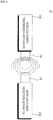
- FIG. 1 is an exemplary block diagram of the internal configuration of a wireless power system according to an embodiment of the present disclosure.
- a single wireless power transmission apparatus 100 may charge a plurality of wireless power reception apparatuses 200.
- the wireless power transmission apparatus 100 may distribute and transmit power to the plurality of wireless power reception apparatuses 200 in a time division manner.
- the present disclosure is not limited thereto.
- the wireless power transmission apparatus 100 may distribute and transmit power to a plurality of wireless power reception apparatuses 200 using different frequency bands allocated to the respective wireless power reception apparatuses 200.
- the number of wireless power reception apparatuses 200 capable of being connected to one wireless power transmission apparatus 100 may be adaptively determined based on the amount of power that is required for each wireless power reception apparatus 200, the amount of power available to the wireless power transmission apparatus 100, and the like.
- the wireless power reception apparatus 200 may be a mobile phone, a laptop computer, a wearable device such a smart watch, a personal digital assistant (PDA), a portable multimedia player (PMP), a navigation device, an MP3 player, an electric toothbrush, a lighting device, and a remote control.
- PDA personal digital assistant
- PMP portable multimedia player
- the wireless power reception apparatus may be any electronic device having a rechargeable battery.
- the information exchanged between the wireless power transmission apparatus 100 and the wireless power reception apparatus 200 may include information about the states thereof, information about the amount of used power, information about the state of charge of a battery, information about voltage/current output from a battery, control information, and the like.
- FIG. 2 is a block diagram of the internal configuration of the wireless power transmission apparatus in the wireless power system shown in FIG. 1 .
- the wireless power transmission apparatus 100 may include a converter 110 for converting commercial alternating-current (AC) power from a commercial AC power source 405 into direct-current (DC) power, a wireless power driver 170 for converting the DC power into AC power, and a coil 180 for wirelessly transmitting power using the converted AC power.
- a converter 110 for converting commercial alternating-current (AC) power from a commercial AC power source 405 into direct-current (DC) power
- DC direct-current
- a wireless power driver 170 for converting the DC power into AC power
- a coil 180 for wirelessly transmitting power using the converted AC power.
- the converter 110 may convert commercial AC power from the commercial AC power source 405 into DC power and may output the DC power.
- the commercial AC power source 405 is illustrated as being a single-phase AC power source in the drawing, it may be a three-phase AC power source.
- the internal structure of the converter 110 may vary depending on the type of the commercial AC power source 405.
- the converter 110 may be constituted by diodes without a switching element, and thus may implement rectification without a separate switching operation.
- the converter 110 may include four diodes in the form of a bridge, and in the case in which the commercial AC power source 405 is a three-phase AC power source, the converter 110 may include six diodes in the form of a bridge.
- the converter 110 may be a half-bridge-type converter in which two switching elements and four diodes are interconnected.
- the converter 110 may include six switching elements and six diodes.
- the controller 160 may control the wireless power driver 170 to wirelessly transmit power to the wireless power reception apparatus 200.
- the wireless power driver 170 may convert the DC power into AC power for wireless power transmission.
- the controller 160 may include a PWM generator 160a for generating a PWM signal and a driver 160b for generating and outputting a driving signal Sic based on the PWM signal.
- the controller 160 may determine the duty of the PWM signal based on the amount of transmitted power, the current flowing through the wireless power driver 170, and the like.
- the PWM generator 160a may generate a PWM signal based on the duty of the PWM signal.
- the driver 160b may output a driving signal Sic for driving the wireless power driver 170 based on the PWM signal.
- the coil 180 may wirelessly transmit power to the wireless power reception apparatus 200 through any one combination of coils selected from among the plurality of coils 181.
- the plurality of coils 181 may be referred to as a plurality of transmission coils 181 so as to distinguish the same from the reception coil 281 shown in FIG. 3 .
- the coil 180 may be referred to as a resonant circuit 180.
- the resonant circuit 180 may include a plurality of coils 181 to 184 and a plurality of capacitor elements 185 to 188 respectively connected to the plurality of coils 181 to 184.
- the resonant circuit 180 may further include a shielding material 190 (refer to FIG. 4 ) disposed at one side of each of the coils 181 to block a leaked magnetic field.
- a shielding material 190 (refer to FIG. 4 ) disposed at one side of each of the coils 181 to block a leaked magnetic field.
- the coil-combination generator 161 may generate combinations of coils including at least one of the coils 181.
- Each of the first communicator 140 and the second communicator 150 may further include a modulator/demodulator (not shown) for modulating or demodulating a data signal transmitted from the wireless power transmission apparatus 100 and a data signal received from the wireless power reception apparatus 200.
- a modulator/demodulator (not shown) for modulating or demodulating a data signal transmitted from the wireless power transmission apparatus 100 and a data signal received from the wireless power reception apparatus 200.
- the first sensor 131 may sense a change in the inductance of each of the coils 181 to 184 based on a change in the resonant frequency f on .
- the resonant frequency f on may be calculated using Equation 1 below, and the first sensor 131 may sense a change in the inductance of each of the coils 181 through the resonant frequency of the resonant circuit 180.
- f on 1 2 ⁇ LC
- each of the coils 181 to 184 or each of the capacitors 185 to 188 may gradually increase and then decrease.
- the resonant frequency f on of each of the coils 181 to 184 may vary depending on the type of object and the location at which the object is placed.
- the first sensor 131 may calculate the inductance of each of the coils 181 to 184 using the resonant frequency f on of each of the coils 181 to 184, may sense a change in the inductance of each of the coils 181 to 184, and may transmit the sensing result to the controller 160.
- the second sensor 133 may calculate the quality factor Q of each of the coils 181 to 184 based on the maximum voltage gain acquired from opposite ends of each of the coils 181 to 184 in accordance with the sweep of the frequency.
- the memory 120 may store the transmission intensity of a coil selection signal transmitted from each of the coils.
- each of the transmission intensity of the object sensing signal and the transmission intensity of the coil selection signal may be the intensity set through factory calibration.
- the memory 120 may store information about a reference region, which is calculated based on the reference quality factor variation and the reference inductance variation.
- the wireless power transmission apparatus 100 does not detect a foreign object on the charging surface using only the inductance variation ⁇ L and/or the quality factor variation ⁇ Q of each of the coils 181 to 184, but detects a foreign object on the charging surface using the average inductance variation ⁇ L/4, the average quality factor variation ⁇ Q/4, the maximum-minimum inductance variation ⁇ Lmax-min, and the maximum-minimum quality factor variation ⁇ Qmax-min.
- the wireless power reception apparatus 200 may include a power receiver 280 for receiving wireless power from the wireless power transmission apparatus 100, a rectifier 210 for rectifying the received wireless power, a switching regulator 220 for stabilizing the rectified wireless power, and a switching regulator controller 230 for controlling the switching regulator 220 to output operating power to a load.
- the first to fourth coils 181 to 184 may be disposed to partially overlap each other. Specifically, as shown in FIG. 4 , the first coil 181 and the second coil 182 may partially overlap each other, the second coil 182 and the third coil 183 may partially overlap each other, and the third coil 183 and the fourth coil 184 may partially overlap each other.
- the first to fourth coils 181 to 184 and the shielding material 190 may be formed in a layered structure.
- the wireless power transmission apparatus 100 may transmit object sensing signals through the coils 181 in a predetermined order, and may sense the presence or absence of an object within the charging area based on variation in the current of the coils with respect to the respective object sensing signals.
- the wireless power transmission apparatus 100 may determine whether a foreign object is present on the charging surface based on whether the combination of feature values selected from the plurality of feature values falls within a reference region on the coordinate plane.
- the wireless power transmission apparatus 100 may determine whether a foreign object is present on the charging surface based on whether the combination of feature values selected from the plurality of feature values falls within a reference region on the coordinate plane.
- the sensing area may be an area in which the wireless power transmission apparatus 100 is capable of transmitting power.
- the sensing area may be a charging area, a charging surface, or an active area of the interface surface, in which the wireless power reception apparatus 200 is charged.
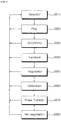
- the wireless power reception apparatus 200 may modulate the digital ping (DP) signal and may transmit the modulated digital ping (DP) signal to the wireless power transmission apparatus 100.
- DP digital ping
- DP modulated digital ping
- the wireless power transmission apparatus 100 may recognize the wireless power reception apparatus 200, which is the target of power transmission, based on the sensing data in a digital form.
- the identification data may include information about the version of a wireless power transfer protocol, information about the manufacturer of the wireless power reception apparatus 200, basic device identifier information, information indicating the presence or absence of an extended device identifier, and the like.
- the wireless power reception apparatus 200 may transmit power data.
- the wireless power transmission apparatus 100 may determine whether to maintain the in-band communication method or to change from the in-band communication method to an out-of-band communication method based on the information about the power of the wireless power reception apparatus 200 acquired in at least one of the selection phase S610, the ping phase S620, or the identification and configuration phase S630.
- the wireless power transmission apparatus 100 may transition to the negotiation phase S650, and may perform a foreign object detection (FOD) procedure.
- FOD foreign object detection
- the wireless power transmission apparatus 100 may directly transition to the power transfer phase S670.
- the wireless power transmission apparatus 100 may determine whether to enter the calibration phase S660 based on the result of determining whether a foreign object is present on the charging surface, which is acquired in the selection phase S610 or the negotiation phase S650.
- the wireless power transmission apparatus 100 may transmit power to the wireless power reception apparatus 200.
- the wireless power transmission apparatus 100 may receive power control information from the wireless power reception apparatus 200 and may adjust the characteristics of the power, which is applied to the coils, in response to the received power control information.
- the wireless power transmission apparatus 100 may transition to the selection phase S610.
- the wireless power transmission apparatus 100 may transition to the re-negotiation phase S680. In this case, when the re-negotiation is normally completed, the wireless power transmission apparatus 100 may return to the power transfer phase S670.
- FIGS. 7 and 8 are views for explaining a reference region according to an embodiment of the present disclosure.
- the reference region may be set based on a region within which each combination of feature values is displayed on the coordinate plane.
- the coordinates, on the basis of which an object is placed on the charging surface may be expressed as shown in FIG. 7 .
- reference numeral 810 denotes the quality factor variation ⁇ Q relative to the inductance variation ⁇ L of the first coil 181 at each coordinate point in FIG. 7
- reference numeral 820 denotes the quality factor variation ⁇ Q relative to the inductance variation ⁇ L of the second coil 182 at each coordinate point in FIG. 7
- reference numeral 830 denotes the quality factor variation ⁇ Q relative to the inductance variation ⁇ L of the third coil 183 at each coordinate point in FIG. 7
- reference numeral 840 denotes the quality factor variation ⁇ Q relative to the inductance variation ⁇ L of the fourth coil 184 at each coordinate point in FIG. 7 .
- the coordinate conversion of the quality factor variation ⁇ Q relative to the inductance variation ⁇ L shown in FIG. 8(a) into average quality factor variation ⁇ Q/4 relative to average inductance variation ⁇ L/4 may be expressed as shown in FIG. 8(b) .
- the absolute value of the quality factor variation ⁇ Q may be used for the coordinate conversion for convenience of calculation.
- the resolution may be increased upon detecting a foreign object. That is, when using the average inductance variation ⁇ L/4 and the average quality factor variation
- /4 may be a combination of feature values calculated based on the inductance variation ⁇ L and the quality factor variation ⁇ Q.
- the reference region may be a region in which each combination of feature values is located on the coordinate plane when only the wireless power reception apparatus 200 is placed on the charging surface.
- the reference region may be the region 890b shown in FIG. 8(b) .
- the memory 120 may store a plurality of reference regions corresponding to the respective combinations of feature values.
- the memory 120 may store a reference region in the coordinate plane of the average inductance variation ⁇ L/4 and the average quality factor variation
- the reference region may be a region in which the average inductance variation ⁇ L/4 is from 1.59 to 2.13 uH and the average quality factor variation
- the reference region may be stored in the memory 120 as a preset value.
- the reference region may be calculated by the controller 160 through the process of receiving a quality factor from the wireless power reception apparatus 200 and of performing correlation matching.
- the calculated reference region may be stored in the memory 120.
- the controller 160 may determine whether a foreign object is present on the charging surface based on whether combinations of feature values fall within the reference region on the coordinate plane.
- the controller 160 may determine that there is no foreign object.
- the controller 160 may determine that there is a foreign object.
- the controller 160 may convert the coordinates of the average inductance variation ⁇ L/4 and the average quality factor variation
- the coordinate conversion will be described in more detail below.
- FIG. 9 is a view for explaining a position at which a foreign object is present on the charging surface
- FIGS. 10 to 15 are reference views for explaining methods of detecting a foreign object.
- FIG. 10 is a view for explaining a method of detecting a foreign object based on a combination of the average inductance variation and the average quality factor variation
- FIG. 11 is a view for explaining a method of detecting a foreign object based on a combination of the average inductance variation and the maximum-minimum quality factor variation
- FIG. 12 is a view for explaining a method of detecting a foreign object based on a combination of the maximum-minimum inductance variation and the average quality factor variation
- FIG. 13 is a view for explaining a method of detecting a foreign object based on a combination of the maximum-minimum inductance variation and the maximum-minimum quality factor variation
- FIG. 10 is a view for explaining a method of detecting a foreign object based on a combination of the average inductance variation and the maximum-minimum quality factor variation
- FIG. 12 is a view for explaining a method of detecting a foreign object based on a combination of the maximum-minimum induct
- FIG. 14 is a view for explaining a method of detecting a foreign object based on a combination of the average inductance variation and the maximum-minimum inductance variation
- FIG. 15 is a view for explaining a method of detecting a foreign object based on a combination of the average quality factor variation and the maximum-minimum quality factor variation.
- the coordinates indicating the positions at which a foreign object is placed on the charging surface may be expressed as shown in FIG. 9 .
- the reason why the number of coordinate points in the coordinates of the charging surface in FIG. 9 is 13 is that it is possible to estimate data at the coordinate points (-20, 20), (-20, 13), (-20, -13), and (-20, -20) and data at the coordinate points corresponding thereto.
- a plurality of combinations of feature values maybe displayed on the corresponding coordinate plane, as shown in FIGS. 10 to 15 .
- reference numerals 1010, 1110, 1210, 1310, 1410 and 1510 may denote the case in which only the wireless power reception apparatus 200 is placed on the charging surface
- reference numerals 1020, 1120, 1220, 1320, 1420 and 1520 may denote the case in which the wireless power reception apparatus 200 and a U.S.
- reference numerals 1030, 1130, 1230, 1330, 1430 and 1530 may denote the case in which the wireless power reception apparatus 200 and a 100-won coin are placed on the charging surface
- reference numerals 1040, 1140, 1240, 1340, 1440 and 1540 may denote the case in which the wireless power reception apparatus 200 and a 10-won coin are placed on the charging surface
- reference numerals 1050, 1150, 1250, 1350, 1450 and 1550 may denote the case in which the wireless power reception apparatus 200 and a 50-won coin are placed on the charging surface
- reference numerals 1060, 1160, 1260, 1360, 1460 and 1560 may denote the case in which the wireless power reception apparatus 200 and a Canadian dime coin are placed on the charging surface.
- FIG. 10 is a view showing the coordinate plane of the average inductance variation ⁇ L/4 and the average quality factor variation
- the reference region may be the region 1070.
- the reference region may be a region in which the average inductance variation ⁇ L/4 is from 1.59 to 2.13 uH and the average quality factor variation
- the controller 160 is likely to determine that no foreign object is present on the charging surface.
- FIG. 11 is a view showing the coordinate plane of the average inductance variation ⁇ L/4 and the maximum-minimum quality factor variation ⁇ Qmax-min, on which the maximum-minimum quality factor variation ⁇ Qmax-min relative to the average inductance variation ⁇ L/4 of the coils 181 to 184 is displayed.
- the reference region may be the region 1170.
- the reference region may be a region in which the average inductance variation ⁇ L/4 is from 1.59 to 2.13 uH and the maximum-minimum quality factor variation ⁇ Qmax-min is from 2.19 to 17.9.
- the controller 160 may accurately detect a foreign object.
- FIG. 12 is a view showing the coordinate plane of the maximum-minimum inductance variation ⁇ Lmax-min and the average quality factor variation
- the reference region may be the region 1270.
- the reference region may be a region in which the maximum-minimum inductance variation ⁇ Lmax-min is from 0.5 to 1.21 uH and the average quality factor variation
- FIG. 13 is a view showing the coordinate plane of the maximum-minimum inductance variation ⁇ Lmax-min and the maximum-minimum quality factor variation ⁇ Qmax-min, on which the maximum-minimum quality factor variation ⁇ Qmax-min relative to the maximum-minimum inductance variation ⁇ Lmax-min of each of the coils 181 to 184 is displayed.
- the reference region may be the region 1370.
- the reference region may be a region in which the maximum-minimum inductance variation ⁇ Lmax-min is from 0.5 to 1.21 uH and the maximum-minimum quality factor variation ⁇ Qmax-min is from 11.19 to 21.04.
- the controller 160 may accurately detect a foreign object.
- FIG. 14 is a view showing the coordinate plane of the average inductance variation ⁇ L/4 and the maximum-minimum inductance variation ⁇ Lmax-min, on which the maximum-minimum inductance variation ⁇ Lmax-min relative to the average inductance variation ⁇ L/4 of the coils 181 to 184 is displayed.
- the reference region may be the region 1470.
- the reference region may be a region in which the average inductance variation ⁇ L/4 is from 1.59 to 2.13 uH and the maximum-minimum inductance variation ⁇ Lmax-min is from 0.5 to 1.21 uH.
- the controller 160 is likely to determine that no foreign object is present on the charging surface.
- FIG. 15 is a view showing the coordinate plane of the average quality factor variation
- the reference region may be the region 1570.
- the reference region may be a region in which the average quality factor variation
- the controller 160 may accurately detect a foreign object.
- FIGS. 10 to 15 illustrate the distribution of the combinations of feature values in the corresponding coordinate plane when the foreign object is a U.S. dime coin, a 100-won coin, a 10-won coin, a 50-won coin, or a Canadian dime coin.
- the regions within which the combinations of feature values are distributed may be different from the regions shown in FIGS. 10 to 15 depending on the size of the foreign object, the material of the foreign object (e.g. a magnetic material, metal, etc.), or the like.
- a specific combination of feature values may be advantageous depending on the type of foreign object.
- /4 or the feature value combination of the average inductance variation ⁇ L/4 and the maximum-minimum inductance variation ⁇ Lmax-min may be advantageous in detecting a foreign object.
- the controller 160 may select a plurality of feature value combinations and use the same to detect a foreign object. For example, the controller 160 may detect a foreign object on the charging surface using a first feature value combination of the average inductance variation ⁇ L/4 and the average quality factor variation
- the controller 160 may detect a foreign object on the charging surface using all of a first feature value combination of the average inductance variation ⁇ L/4 and the average quality factor variation
- the wireless power transmission apparatus 100 of the present disclosure detects a foreign object on the charging surface using a plurality of combinations of feature values, thereby more accurately detecting a foreign object.
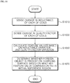
- FIG. 16 is a flowchart for explaining a method of detecting a foreign object according to an embodiment of the present disclosure.
- the wireless power transmission apparatus 100 may sense a change in the inductance of each of the coils 181 to 184 (S1610).
- the inductance of each of the coils 181 to 184 may change.
- variation in the inductance of each of the coils 181 to 184 may vary depending on the type of object and the location at which the object is placed.
- the first sensor 131 may sense a change in the inductance of each of the coils 181 to 184 based on a change in the resonant frequency f on .
- the first sensor 131 may calculate the resonant frequency f on of each of the coils 181 to 184 based on the magnitude of voltage acquired from opposite ends of each of the coils 181 to 184 in accordance with the sweep of the frequency.
- the first sensor 131 may calculate the inductance of each of the coils 181 to 184 using the resonant frequency f on .
- the first sensor 131 may sense a change in the inductance of each of the coils 181 to 184 and may transmit the sensing result to the controller 160.
- the wireless power transmission apparatus 100 may sense a change in the quality factor of each of the coils 181 to 184 (S1630).
- the inductance of each of the coils 181 to 184 and/or the series resistance component in each of the coils 181 to 184 may change. Accordingly, the voltage across the opposite ends of each of the coils 181 to 184 may also change.
- the second sensor 133 may calculate the quality factor of each of the coils 181 to 184 based on the maximum voltage gain acquired from opposite ends of each of the coils 181 to 184 in accordance with the sweep of the frequency.
- the second sensor 133 may sense a change in the quality factor of each of the coils 181 to 184 and may transmit the sensing result to the controller 160.
- the controller 160 of the wireless power transmission apparatus 100 may calculate a plurality of feature values for detecting a foreign object based on the inductance variation and the quality factor variation (S1650).
- the controller 160 may calculate a plurality of feature values for detecting a foreign object based on the inductance variation ⁇ L and the quality factor variation ⁇ Q.
- the feature values may refer to factors that are specially used to detect a foreign object in the embodiment of the present disclosure among the factors that change.
- the feature values may include average inductance variation ⁇ L/4, average quality factor variation ⁇ Q/4, maximum-minimum inductance variation ⁇ Lmax-min, and maximum-minimum quality factor variation ⁇ Qmax-min.
- the average inductance variation ⁇ L/4 may be the average of the inductance variations of the coils 181 to 184, and the average quality factor variation ⁇ Q/4 may be the average of the quality factor variations of the coils 181 to 184.
- the maximum-minimum inductance variation ⁇ Lmax-min may be the difference between the maximum inductance variation and the minimum inductance variation among the coils 181 to 184
- the maximum-minimum quality factor variation ⁇ Qmax-min may be the difference between the maximum quality factor variation and the minimum quality factor variation among the coils 181 to 184.
- the wireless power transmission apparatus 100 of the present disclosure uses the average variation and the maximum-minimum variation, rather than using a ratio of the inductance variation or a ratio of the quality factor variation, the foreign object calculation process is simple, and the detection of a foreign object is rapidly realized.
- the controller 160 of the wireless power transmission apparatus 100 may determine whether a foreign object is present on the charging surface based on whether the combination of feature values selected from the plurality of feature values falls within a reference region on the coordinate plane (S1670).
- the controller 160 may generate a combination of two feature values selected from the plurality of feature values.
- the controller 160 may generate a first feature value combination of the average inductance variation ⁇ L/4 and the average quality factor variation ⁇ Q/4, a second feature value combination of the average inductance variation ⁇ L/4 and the maximum-minimum quality factor variation ⁇ Qmax-min, a third feature value combination of the maximum-minimum inductance variation ⁇ Lmax-min and the average quality factor variation ⁇ Q/4, a fourth feature value combination of the maximum-minimum inductance variation ⁇ Lmax-min and the maximum-minimum quality factor variation ⁇ Qmax-min, a fifth feature value combination of the average inductance variation ⁇ L/4 and the maximum-minimum inductance variation ⁇ Lmax-min, and a sixth feature value combination of the average quality factor variation ⁇ Q/4 and the
- the controller 160 may select a plurality of feature value combinations from among the first to sixth feature value combinations. For example, the controller 160 may select the first feature value combination and the second feature value combination. Alternatively, the controller 160 may select all of the first to sixth feature value combinations.
- the controller 160 may determine whether a foreign object is present on the charging surface based on whether the combination of feature values selected from among the plurality of feature values falls within the reference region on the coordinate plane.
- the reference region may be set based on a region within which each combination of feature values is displayed on the corresponding coordinate plane.
- the memory 120 may store a plurality of reference regions corresponding to the respective combinations of feature values.
- the controller 160 may determine that no foreign object is present on the charging surface.
- controller 160 may start wireless transmission of power to the wireless power reception apparatus 200.
- the controller 160 may determine that no foreign object is present on the charging surface and may start charging.
- the controller 160 may determine that a foreign object is present on the charging surface.
- controller 160 may interrupt the wireless transmission of power to the wireless power reception apparatus 200.
- the controller 160 may determine that a foreign object is present on the charging surface and may stop charging.
- the controller 160 may continuously detect a foreign object on the charging surface.
- FIG. 17 is a flowchart for explaining a method of detecting a foreign object according to an embodiment of the present disclosure.
- the wireless power transmission apparatus 100 may select the first feature value combination from among the first to sixth feature value combinations.
- the first feature value combination may be a combination of the average inductance variation ⁇ L/4 and the average quality factor variation ⁇ Q/4.
- the controller 160 may display the first feature value combination selected from the plurality of feature values on the corresponding coordinate plane (S1711).
- the controller 160 may display the average quality factor variation ⁇ Q/4 relative to the average inductance variation ⁇ L/4 on the corresponding coordinate plane.
- the controller 160 may determine whether the first feature value combination falls within a first reference region (S1713).
- the first reference region may be set based on a region within which the combination of the average inductance variation ⁇ L/4 and the average quality factor variation ⁇ Q/4 is distributed on the coordinate plane of the average inductance variation ⁇ L/4 and the average quality factor variation ⁇ Q/4.
- the first reference region may be the region 1070 shown in FIG. 10 .
- the first reference region is set based on a region within which the combination of the average inductance variation ⁇ L/4 and the average quality factor variation ⁇ Q/4 is distributed on the corresponding coordinate plane.
- the controller 160 may determine that a foreign object is present on the charging surface (S1715).
- the controller 160 may stop charging (S1717). Accordingly, it is possible to protect a user from dangers such as an explosion or a fire.
- the controller 160 may determine that no foreign object is present on the charging surface.
- the controller 160 may continuously determine the presence or absence of a foreign object while changing the feature value combinations.
- the controller 160 may select a second feature value combination (S1719).
- the controller 160 may generate the second feature value combination such that at least one of the feature values included in the second feature value combination is different from the feature values included in the first feature value combination.
- the second feature value combination may be a combination of the average inductance variation ⁇ L/4 and the maximum-minimum quality factor variation ⁇ Qmax-min.
- the controller 160 may display the second feature value combination on the corresponding coordinate plane (S1721).
- the controller 160 may display the maximum-minimum quality factor variation ⁇ Qmax-min relative to the average inductance variation ⁇ L/4 on the corresponding coordinate plane.
- the controller 160 may determine whether the second feature value combination falls within a second reference region (S1723).
- the second reference region may be set based on a region within which the combination of the average inductance variation ⁇ L/4 and the maximum-minimum quality factor variation ⁇ Qmax-min is distributed on the coordinate plane of the average inductance variation ⁇ L/4 and the maximum-minimum quality factor variation ⁇ Qmax-min.
- the second reference region may be the region 1170 shown in FIG. 11 .
- the controller 160 may determine that a foreign object is present on the charging surface (S1725). That is, the controller 160 may detect a foreign object that is not detected by the first feature value combination. Accordingly, there is an effect in that the accuracy of foreign object detection is improved.
- the controller 160 may stop charging (S1727).
- the controller 160 may determine that no foreign object is present on the charging surface (S1729).
- the controller 160 may start charging (S1731).
- the wireless power transmission apparatus 100 uses only the first and second feature value combinations among the first to sixth feature value combinations, it is possible to shorten a time taken to detect a foreign object while increasing the accuracy of foreign object detection.
- the controller 160 of the present disclosure may be implemented as code that can be written on a processor-readable recording medium and thus read by a processor provided in the power transmission apparatus 100.
- the processor-readable recording medium may be any type of recording device in which data is stored in a processor-readable manner.
- the processor-readable recording medium may include, for example, ROM, RAM, CD-ROM, magnetic tape, a floppy disk, and an optical data storage device, and may be implemented in the form of a carrier wave transmitted over the Internet.
- the processor-readable recording medium may be distributed over computer systems connected via a network such that processor-readable code is written thereto and executed therefrom in a decentralized manner.
- a wireless power transmission apparatus calculates a plurality of feature values for detecting a foreign object based on inductance variation and quality factor variation, and determines the presence or absence of a foreign object on a charging surface depending on whether a feature value combination selected from the plurality of feature values falls within a reference region on a corresponding coordinate plane, thereby more accurately detecting a foreign object than a configuration of detecting a foreign object based on only one of inductance variation and quality factor variation.
- the wireless power transmission apparatus may accurately detect a foreign object regardless of the size of the foreign object, the material of the foreign object (e.g. a magnetic material, a non-magnetic material, etc.), or the like, using a combination of feature values selected from among average inductance variation, average quality factor variation, maximum-minimum inductance variation, and maximum-minimum quality factor variation.
Landscapes
- Engineering & Computer Science (AREA)
- Power Engineering (AREA)
- Computer Networks & Wireless Communication (AREA)
- Physics & Mathematics (AREA)
- General Physics & Mathematics (AREA)
- Electromagnetism (AREA)
- Remote Sensing (AREA)
- Life Sciences & Earth Sciences (AREA)
- Environmental & Geological Engineering (AREA)
- Geology (AREA)
- General Life Sciences & Earth Sciences (AREA)
- Geophysics (AREA)
- Charge And Discharge Circuits For Batteries Or The Like (AREA)
Description
- This application claims the priority benefit of Korean Patent Application No.
1 0-2018-0142208, filed on NOV 19, 2018 - The present disclosure relates to a wireless power transmission apparatus, and more particularly to a wireless power apparatus capable of easily detecting a foreign object on a charging surface.
- As a method of supplying power to an electronic device, there is a terminal supply method of interconnecting a commercial power source and an electronic device using physical cables or wires. However, the terminal supply method has problems in that the cables or wires occupy a large space, are difficult to arrange, and entail the risk of disconnection.
- In order to solve these problems, studies have recently been conducted to develop a wireless power transmission method.
- A wireless power transmission system may include a wireless power transmission apparatus for supplying power through a single coil or multiple coils, and a wireless power reception apparatus for receiving and using the power wirelessly supplied from the wireless power transmission apparatus.
- An inductive coupling method is mainly used as a wireless power supply method. The inductive coupling method uses a principle in which when the intensity of current flowing through a primary coil of two adjacent coils is changed, a magnetic field is changed by the current, a magnetic flux flowing through a secondary coil is changed, and an induced electromotive force is generated at the secondary coil. That is, according to this method, it is possible to generate an induced electromotive force by changing only current flowing through the primary coil in the state in which two coils are spaced apart from each other without moving two conducting wires.
- However, the inductive coupling method, which has non-contact charging characteristics, has problems in that when a foreign object is present between a wireless power transmission apparatus and a wireless power reception apparatus during charging, overload, burning or explosion of a product may occur due to deterioration attributable to the foreign object.
- Therefore, there is the need to develop a method of more easily detecting a foreign object on a charging surface of a wireless power transmission apparatus.
- "Wireless Power System" disclosed in
U.S. Patent No. 9,825,486 B2 - However, the "Wireless Power System" described above requires a separate detection coil for detecting a foreign object in addition to a power transmission coil. Thus, manufacturing costs increase, and a circuit becomes complicated.
- "Wireless Charging Apparatus" disclosed in Korean Patent Laid-open Publication No.
10-2018-0065693 - However, like the "Wireless Charging Apparatus" described above, the one-dimensional foreign object detection method using only a peak frequency without comprehensive consideration of inductance variation, quality factor variation, and the like may cause an error in detecting a foreign object. In particular, the "Wireless Charging Apparatus" described above is characterized by a single coil and proposes a method of solving a problem in that the peak frequency varies depending on the location of a power reception apparatus Rx by adding a predetermined allowable error value to the maximum peak frequency variation. However, the addition of the error value may further deteriorate accuracy of detection of a foreign object.
-
US 2017/117756 (A1) relates to detection of foreign objects in the field produced by a wireless power transmitter. - Therefore, the present disclosure has been made in view of the above problems, and it is an object of the present disclosure to provide a wireless power transmission apparatus capable of more accurately detecting a foreign object on a charging surface using multiple coils disposed so as to partially overlap each other.
- It is another object of the present disclosure to provide a wireless power transmission apparatus capable of more easily detecting a foreign object within a wide range on a charging surface using multiple coils disposed so as to partially overlap each other.
- It is still another object of the present disclosure to provide a wireless power transmission apparatus enabling two-dimensional foreign object detection by displaying a plurality of feature values extracted from inductance variation and quality factor variation on a coordinate plane.
- It is still another object of the present disclosure to provide a wireless power transmission apparatus capable of detecting a foreign object on a charging surface without a separate module.
- However, the objects to be accomplished by the disclosure are not limited to the above-mentioned objects, and other objects not mentioned herein will be clearly understood by those skilled in the art from the following description.
- In accordance with the present disclosure, the above and other objects can be accomplished by the provision of a wireless power transmission apparatus as defined in
claim 1 and a wireless power transmission method as defined in claim 14. Preferred embodiments are defined by the dependent claims. - The above and other objects, features and other advantages of the present disclosure will be more clearly understood from the following detailed description taken in conjunction with the accompanying drawings, in which:
-
FIG. 1 is an exemplary block diagram of the internal configuration of a wireless power system according to an embodiment of the present disclosure; -
FIG. 2 is a block diagram of the internal configuration of a wireless power transmission apparatus in the wireless power system shown inFIG. 1 ; -
FIG. 3 is a block diagram of the internal configuration of a wireless power reception apparatus in the wireless power system shown inFIG. 1 ; -
FIG. 4 is a view for explaining the structure of a coil shown inFIG. 2 ; -
FIG. 5 is a perspective view showing the layer structure of the coil shown inFIG. 4 ; -
FIG. 6 is a flowchart for explaining a wireless power transmission method according to an embodiment of the present disclosure; -
FIG. 7 is a view for explaining a reference region according to an embodiment of the present disclosure; -
FIG. 8 is a view for explaining a reference region according to an embodiment of the present disclosure; -
FIG. 9 is a view for explaining a position at which a foreign object is present on a charging surface; -
FIG. 10 is a view for explaining a method of detecting a foreign object based on a combination of average inductance variation and average quality factor variation; -
FIG. 11 is a view for explaining a method of detecting a foreign object based on a combination of average inductance variation and maximum-minimum quality factor variation; -
FIG. 12 is a view for explaining a method of detecting a foreign object based on a combination of maximum-minimum inductance variation and average quality factor variation; -
FIG. 13 is a view for explaining a method of detecting a foreign object based on a combination of maximum-minimum inductance variation and maximum-minimum quality factor variation; -
FIG. 14 is a view for explaining a method of detecting a foreign object based on a combination of average inductance variation and maximum-minimum inductance variation; -
FIG. 15 is a view for explaining a method of detecting a foreign object based on a combination of average quality factor variation and maximum-minimum quality factor variation; -
FIG. 16 is a flowchart for explaining a method of detecting a foreign object according to an embodiment of the present disclosure; and -
FIG. 17 is a flowchart for explaining a method of detecting a foreign object according to an embodiment of the present disclosure. - Reference will now be made in detail to the preferred embodiments of the present disclosure, examples of which are illustrated in the accompanying drawings.
- Terms including ordinal numbers such as first, second, etc. may be used to explain various elements. However, it will be appreciated that the elements are not limited to such terms. These terms are merely used to distinguish one element from another.
- It will be further understood that terms such as "include" or "have", when used in this specification, specify the presence of stated features, integers, steps, operations, elements, components, or combinations thereof, but do not preclude the presence or addition of one or more other features, integers, steps, operations, elements, components, or combinations thereof.
-
FIG. 1 is an exemplary block diagram of the internal configuration of a wireless power system according to an embodiment of the present disclosure. - Referring to the drawing, a
wireless power system 10 may include a wirelesspower transmission apparatus 100, which wirelessly transmits power, and a wirelesspower reception apparatus 200, which receives the wirelessly transmitted power. - The wireless
power transmission apparatus 100 may transmit power to the wirelesspower reception apparatus 200 using a magnetic induction phenomenon in which current is induced to areception coil 281 by changing a magnetic field of acoil 181. In this case, the wirelesspower transmission apparatus 100 and the wirelesspower reception apparatus 200 may perform wireless charging using an electromagnetic induction scheme defined by the Wireless Power Consortium (WPC) or the Power Matters Alliance (PMA). Alternatively, the wirelesspower transmission apparatus 100 and the wirelesspower reception apparatus 200 may perform wireless charging using a magnetic resonance scheme defined by the Alliance for Wireless Power (A4WP). - The wireless
power transmission apparatus 100 may wirelessly transmit power to the wirelesspower reception apparatus 200 to charge the same. - In one example, a single wireless
power transmission apparatus 100 may charge a plurality of wirelesspower reception apparatuses 200. In this case, the wirelesspower transmission apparatus 100 may distribute and transmit power to the plurality of wirelesspower reception apparatuses 200 in a time division manner. However, the present disclosure is not limited thereto. In another example, the wirelesspower transmission apparatus 100 may distribute and transmit power to a plurality of wirelesspower reception apparatuses 200 using different frequency bands allocated to the respective wirelesspower reception apparatuses 200. The number of wirelesspower reception apparatuses 200 capable of being connected to one wirelesspower transmission apparatus 100 may be adaptively determined based on the amount of power that is required for each wirelesspower reception apparatus 200, the amount of power available to the wirelesspower transmission apparatus 100, and the like. - In still another example, a plurality of wireless
power transmission apparatuses 100 may charge at least one wirelesspower reception apparatus 200. In this case, the at least one wirelesspower reception apparatus 200 may be simultaneously connected to the plurality of wirelesspower transmission apparatuses 100, and may be charged by simultaneously receiving power from the wirelesspower transmission apparatuses 100 connected thereto. The number of wirelesspower transmission apparatuses 100 may be adaptively determined based on the amount of power that is required for each wirelesspower reception apparatus 200, the amount of power available to each of the wirelesspower transmission apparatuses 100, and the like. - The wireless
power reception apparatus 200 may receive power transmitted from the wirelesspower transmission apparatus 100. - For example, the wireless
power reception apparatus 200 may be a mobile phone, a laptop computer, a wearable device such a smart watch, a personal digital assistant (PDA), a portable multimedia player (PMP), a navigation device, an MP3 player, an electric toothbrush, a lighting device, and a remote control. However, the present disclosure is not limited thereto. The wireless power reception apparatus may be any electronic device having a rechargeable battery. - The wireless
power transmission apparatus 100 and the wirelesspower reception apparatus 200 may perform bidirectional communication. In some embodiments, the wirelesspower transmission apparatus 100 and the wirelesspower reception apparatus 200 may perform unidirectional communication or half-duplex communication. - Here, the communication scheme may be an in-band communication scheme, which uses the same frequency band as the wireless
power reception apparatus 200, and/or an out-of-band communication scheme, which uses a different frequency band from the wirelesspower reception apparatus 200. - In one example, the information exchanged between the wireless
power transmission apparatus 100 and the wirelesspower reception apparatus 200 may include information about the states thereof, information about the amount of used power, information about the state of charge of a battery, information about voltage/current output from a battery, control information, and the like. -
FIG. 2 is a block diagram of the internal configuration of the wireless power transmission apparatus in the wireless power system shown inFIG. 1 . - Referring to the drawing, the wireless
power transmission apparatus 100 may include aconverter 110 for converting commercial alternating-current (AC) power from a commercialAC power source 405 into direct-current (DC) power, awireless power driver 170 for converting the DC power into AC power, and acoil 180 for wirelessly transmitting power using the converted AC power. - In addition, in order to realize transmission of power and communication, the wireless
power transmission apparatus 100 may further include acontroller 160 for controlling the internal configuration of the wirelesspower transmission apparatus 100, a coil-combination generator 161 for generating combinations of coils including at least one of a plurality ofcoils 181 to 184, first andsecond communicators power reception apparatus 200 using a predetermined communication scheme, afirst sensor 131 for sensing a change in inductance of each of the plurality of coils, asecond sensor 133 for sensing a change in a quality factor of each of the plurality of coils, and amemory 120 for storing a control program for driving the wirelesspower transmission apparatus 100. - The wireless
power transmission apparatus 100 may be operated by DC power, which may be supplied from theconverter 110, which converts commercial AC power into DC power. - The
converter 110 may convert commercial AC power from the commercialAC power source 405 into DC power and may output the DC power. Although the commercialAC power source 405 is illustrated as being a single-phase AC power source in the drawing, it may be a three-phase AC power source. The internal structure of theconverter 110 may vary depending on the type of the commercialAC power source 405. - The
converter 110 may be constituted by diodes without a switching element, and thus may implement rectification without a separate switching operation. - For example, in the case in which the commercial
AC power source 405 is a single-phase AC power source, theconverter 110 may include four diodes in the form of a bridge, and in the case in which the commercialAC power source 405 is a three-phase AC power source, theconverter 110 may include six diodes in the form of a bridge. - Alternatively, the
converter 110 may be a half-bridge-type converter in which two switching elements and four diodes are interconnected. In the case in which the commercialAC power source 405 is a three-phase AC power source, theconverter 110 may include six switching elements and six diodes. - When DC power is supplied from the
converter 110 to thewireless power driver 170 during wireless power transmission, thecontroller 160 may control thewireless power driver 170 to wirelessly transmit power to the wirelesspower reception apparatus 200. In this case, thewireless power driver 170 may convert the DC power into AC power for wireless power transmission. - Specifically, the
controller 160 may include aPWM generator 160a for generating a PWM signal and adriver 160b for generating and outputting a driving signal Sic based on the PWM signal. - The
controller 160 may determine the duty of the PWM signal based on the amount of transmitted power, the current flowing through thewireless power driver 170, and the like. ThePWM generator 160a may generate a PWM signal based on the duty of the PWM signal. Thedriver 160b may output a driving signal Sic for driving thewireless power driver 170 based on the PWM signal. - The
wireless power driver 170 may include at least one switching element (not shown) for converting DC power into AC power. For example, when the switching element is an IBGT, a gate driving signal may be output from thedriver 160b and may be input to a gate terminal of the switching element. In addition, the switching element may perform a switching operation in response to the gate driving signal. DC power may be converted into AC power by the switching operation of the switching element, and may be output to thecoil 180. - In some embodiments, the
wireless power driver 170 may be included in thecontroller 160. - The
coil 180 may include a plurality ofcoils 181 to 184 (hereinafter, denoted by 181 when there is no need to distinguish therebetween). Thecoils 181 may partially overlap each other. - The
coil 180 may wirelessly transmit power to the wirelesspower reception apparatus 200 through any one combination of coils selected from among the plurality ofcoils 181. - The plurality of
coils 181 may be referred to as a plurality of transmission coils 181 so as to distinguish the same from thereception coil 281 shown inFIG. 3 . - Since the plurality of transmission coils 181 is spaced apart from the
reception coil 281, leakage inductance is high and a coupling factor is low, thus leading to deterioration of transmission efficiency. - Therefore, in order to improve transmission efficiency, the wireless
power transmission apparatus 100 of the present disclosure may connect a capacitor to each of the plurality of transmission coils 181 to form a resonant circuit with thereception coil 281. - In the case in which the
coil 180 forms a resonant circuit, thecoil 180 may be referred to as aresonant circuit 180. - The
resonant circuit 180 may include a plurality ofcoils 181 to 184 and a plurality ofcapacitor elements 185 to 188 respectively connected to the plurality ofcoils 181 to 184. - Each of the
capacitor elements 185 to 188 may be connected in series to a respective one of thecoils 181 to 184 to form a resonant circuit. - In some embodiments, unlike
FIG. 2 , each of thecapacitor elements 185 to 188 may be connected in parallel to a respective one of thecoils 181 to 184 to form a resonant circuit. - The
coils 181 to 184 and thecapacitor elements 185 to 188 may determine the resonant frequency of power transmission. - The
resonant circuit 180 may further include a shielding material 190 (refer toFIG. 4 ) disposed at one side of each of thecoils 181 to block a leaked magnetic field. - The structure of the
resonant circuit 180 will be described in more detail later with reference toFIG. 4 . - The coil-
combination generator 161 may generate combinations of coils including at least one of thecoils 181. - The
first communicator 140 may communicate with the wirelesspower reception apparatus 200 using a first communication scheme. Thefirst communicator 140 may process information about the state of the wirelesspower transmission apparatus 100, power control information, and the like into certain signals, and may transmit the processed signals to the wirelesspower reception apparatus 200. In addition, thefirst communicator 140 may receive information about the state of the wirelesspower reception apparatus 200, information about the amount of used power, charging efficiency information, and the like, may process these pieces of information into certain signals, and may transmit the processed signals to thecontroller 160. - The
second communicator 150 may communicate with the wirelesspower reception apparatus 200 using a second communication scheme, which is different from the first communication scheme. Thesecond communicator 150 may process information about the state of the wirelesspower transmission apparatus 100, power control information, and the like into certain signals, and may transmit the processed signals to the wirelesspower reception apparatus 200. In addition, thesecond communicator 150 may receive information about the state of the wirelesspower reception apparatus 200, information about the amount of used power, charging efficiency information, and the like, may process these pieces of information into certain signals, and may transmit the processed signals to thecontroller 160. - Each of the
first communicator 140 and thesecond communicator 150 may further include a modulator/demodulator (not shown) for modulating or demodulating a data signal transmitted from the wirelesspower transmission apparatus 100 and a data signal received from the wirelesspower reception apparatus 200. - In addition, each of the
first communicator 140 and thesecond communicator 150 may further include a filter (not shown) for filtering a data signal from the wirelesspower reception apparatus 200. In this case, the filter (not shown) may include a band pass filter (BPF). - The first communication scheme may be an in-band communication scheme, which uses the same frequency band as the wireless
power reception apparatus 200, and the second communication scheme may be an out-of-band communication scheme, which uses a different frequency band from the wirelesspower reception apparatus 200. - The wireless
power transmission apparatus 100 may change a communication scheme based on information about the power of the wirelesspower reception apparatus 200. - When an object is placed on a charging surface, the inductance of each of the
coils 181 to 184 may change. In addition, variation in the inductance of each of thecoils 181 to 184 may vary depending on the type of object and the location at which the object is placed. - In one example, since the wireless
power reception apparatus 200 includes a magnetic shield (a shielding material) having high permeability, when the wirelesspower reception apparatus 200 is aligned with thefirst coil 181, the inductance of thefirst coil 181 may be increased. - In another example, when a metal material is aligned with the
first coil 181, the inductance of thefirst coil 181 may be reduced. - The
first sensor 131 may sense a change in the inductance of each of thecoils 181 to 184 based on a change in the resonant frequency fon. - Specifically, the resonant frequency fon may be calculated using
Equation 1 below, and thefirst sensor 131 may sense a change in the inductance of each of thecoils 181 through the resonant frequency of theresonant circuit 180.
- In this case, the resonant frequency fon may be calculated based on the magnitude of voltage acquired from opposite ends of each of the
coils 181 to 184 or each of thecapacitors 185 to 188. - More specifically, the
first sensor 131 may sweep the frequency to sense the voltage across the opposite ends of each of thecoils 181 to 184 or each of thecapacitors 185 to 188. In this case, the frequency may be the operating frequency of the wirelesspower transmission apparatus 100. - The
first sensor 131 may sense the voltage across the opposite ends of each of thecoils 181 to 184 or each of thecapacitors 185 to 188 while sweeping from the minimum frequency to the maximum frequency in the frequency band. - The
first sensor 131 may include a first voltage sensor (not shown) for sensing the voltage across the opposite ends of each of thecoils 181 to 185 or each of thecapacitors 185 to 188. - As the frequency increases, the voltage across the opposite ends of each of the
coils 181 to 184 or each of thecapacitors 185 to 188 may gradually increase and then decrease. - The
first sensor 131 may calculate the resonant frequency fon of each of thecoils 181 to 184 based on the maximum voltage gain acquired from opposite ends of each of thecoils 181 to 184 in accordance with the sweep of the frequency. - The
first sensor 131 may calculate a frequency corresponding to the maximum voltage gain as the resonant frequency fon of each of thecoils 181 to 184. - The resonant frequency fon of each of the
coils 181 to 184 may vary depending on the type of object and the location at which the object is placed. Thefirst sensor 131 may calculate the inductance of each of thecoils 181 to 184 using the resonant frequency fon of each of thecoils 181 to 184, may sense a change in the inductance of each of thecoils 181 to 184, and may transmit the sensing result to thecontroller 160. - When an object is placed on the charging surface, the voltage across the opposite ends of each of the
coils 181 to 184 may change, and thus the quality factor Q of each of thecoils 181 to 184 may also change. - The
second sensor 133 may calculate the quality factor Q of each of thecoils 181 to 184 based on the maximum voltage gain acquired from opposite ends of each of thecoils 181 to 184 in accordance with the sweep of the frequency. - Specifically, the quality factor Q may be calculated using Equation 2 below. Here, Q may be the quality factor, V2 may be the maximum voltage gain, and V1 may be the input voltage.

- That is, the
second sensor 133 may calculate the quality factor Q of each of thecoils 181 to 184 based on the maximum voltage gain acquired from opposite ends of each of thecoils 181 to 184 in accordance with the sweep of the frequency. - Thus, the
second sensor 133 may include a second voltage sensor (not shown) for sensing the voltage across the opposite ends of each of thecoils 181 to 184 or each of thecapacitors 185 to 188. - The maximum voltage gain V2 of each of the
coils 181 to 184 may vary depending on the type of object and the location at which the object is placed. Thesecond sensor 133 may calculate the quality factor Q of each of thecoils 181 to 184 using the maximum voltage gain V2 of each of thecoils 181 to 184, may sense a change in the quality factor of each of thecoils 181 to 184, and may transmit the sensing result to thecontroller 160. - The
memory 120 may store a program for operating thepower transmission apparatus 100. - In addition, the
memory 120 may store the transmission intensity of an object sensing signal transmitted from each of the coils to sense the object on the charging surface. - In addition, the
memory 120 may store the transmission intensity of a coil selection signal transmitted from each of the coils. - In this case, each of the transmission intensity of the object sensing signal and the transmission intensity of the coil selection signal may be the intensity set through factory calibration.
- Specifically, as shown in
FIG. 4 , thecoils 181 to 184 of the present disclosure partially overlap each other to form layers therebetween. Thus, although the coils transmit the object sensing signals and the coil selection signals with the same transmission intensity, the intensities of the object sensing signals and the coil selection signals in the charge surface, on which the wirelesspower reception apparatus 200 is placed, may be different from each other. - The difference in the intensity between the object sensing signals and between the coil selection signals in the charging surface may cause an error in sensing the object and combining the operating coils.
- In order to solve this problem, the transmission intensities of the object sensing signals and the transmission intensities of the coil selection signals may be set in consideration of the distance between each of the coils and the charging surface on which the wireless
power reception apparatus 200 is placed. - For example, when the distance between the charging surface and the coil increases, the transmission intensity of the object sensing signal and the transmission intensity of the coil selection signal may be set to gradually increase.
- Accordingly, the intensities of the object sensing signals in the charging surface, on which the wireless
power reception apparatus 200 is placed, may be the same. In addition, the intensities of the coil selection signals in the charging surface may be the same. The corrected transmission intensities of the object sensing signals and the corrected transmission intensities of the coil selection signals may be values set through factory calibration, and may be stored in thememory 120. - The
memory 120 may store reference resonant frequency variation, reference quality factor variation, and reference inductance variation in a normal state. Here, the normal state may be the state in which only the wirelesspower reception apparatus 200 is present on the charging surface, without a foreign object thereon. - In particular, the
memory 120 may store information about a reference region, which is calculated based on the reference quality factor variation and the reference inductance variation. - The
memory 120 may store a plurality of reference regions corresponding to combinations of feature values to be described later. - The
controller 160 may control the overall operation of the wirelesspower transmission apparatus 100. - The
controller 160 may select a combination of operating coils to be used for wireless power transmission from the combinations of coils generated by the coil-combination generator 161, and may charge the wirelesspower reception apparatus 200 through the selected combination of operating coils. - Specifically, the
controller 160 may transmit a coil selection signal and may receive a response signal with respect to the coil selection through the coil included in the combination of coils. - In addition, the
controller 160 may select a combination of operating coils to be used for wireless power transmission while combining the coils based on the intensity of the response signal and the charging efficiency of the wirelesspower reception apparatus 200. - The
controller 160 may wirelessly transmit power to the wirelesspower reception apparatus 200 through the combination of operating coils. - The coil-
combination generator 161 may transmit an object sensing signal through thecoils 181, and may calculate ineffective coils based on variation in the current of the object sensing signal. - In addition, the coil-
combination generator 161 may generate combinations of effective coils, excluding ineffective coils among thecoils 181. - In this case, the
controller 160 may select a combination of operating coils to be used for wireless power transmission from the combinations of effective coils. - The coil-
combination generator 161 may calculate the power of the wirelesspower reception apparatus 200 based on the inherent information about the wirelesspower reception apparatus 200, which is received through thecoil 180, and may calculate the number of operating coils based on the calculated power of the wirelesspower reception apparatus 200. - In addition, the coil-
combination generator 161 may generate combinations of coils in accordance with the number of operating coils. - Unlike
FIG. 2 , the coil-combination generator 161 may be a component included in thecontroller 160. That is, the coil-combination generator 161 may be implemented as a part of thecontroller 160. - In particular, the
controller 160 may determine whether a foreign object is present on the charging surface. - Specifically, the
controller 160 may receive information about a change in the inductance of each of thecoils 181 to 184, which is sensed by thefirst sensor 131, and information about a change in the quality factor of each of thecoils 181 to 184, which is sensed by thesecond sensor 133, and may calculate an inductance variation ΔL and a quality factor variation ΔQ of each of thecoils 181 to 184. - The
controller 160 may calculate a plurality of feature values for detecting a foreign object based on the inductance variation ΔL and the quality factor variation ΔQ. In this case, when an object or a foreign object is present on the charging surface, the feature values may refer to factors that are specially used to detect a foreign object in the embodiment of the present disclosure among the factors that change. - In this case, the feature values may include average inductance variation ΔL/4, average quality factor variation ΔQ/4, maximum-minimum inductance variation ΔLmax-min, and maximum-minimum quality factor variation ΔQmax-min.
- The wireless
power transmission apparatus 100 according to the embodiment of the present disclosure does not detect a foreign object on the charging surface using only the inductance variation ΔL and/or the quality factor variation ΔQ of each of thecoils 181 to 184, but detects a foreign object on the charging surface using the average inductance variation ΔL/4, the average quality factor variation ΔQ/4, the maximum-minimum inductance variation ΔLmax-min, and the maximum-minimum quality factor variation ΔQmax-min. Thus, the wirelesspower transmission apparatus 100 does not sensitively respond to a change in the threshold of the inductance variation ΔL and/or the quality factor variation ΔQ of each of thecoils 181 to 184, but is capable of more accurately detecting a foreign object in a wider area. - The
controller 160 may select a combination of feature values from a plurality of feature values. Thecontroller 160 may determine whether a foreign object is present on the charging surface based on whether the combination of feature values selected from the plurality of feature values falls within a reference region on the coordinate plane. - The wireless
power transmission apparatus 100 according to the embodiment of the present disclosure may display a plurality of feature values extracted from the inductance variation ΔL and the quality factor variation ΔQ on the coordinate plane, and may two-dimensionally detect a foreign object based thereon, thereby detecting a foreign object more accurately than a configuration of one-dimensionally detecting a foreign object based on only one of the inductance variation ΔL and the quality factor variation Δ Q. - A foreign object detection method of the wireless
power transmission apparatus 100 will be described in more detail later with reference toFIG. 7 . The wirelesspower transmission apparatus 100 according to the embodiment of the present disclosure may further include a sensor (not shown) for measuring the temperature of each of thecoils 181 to 184 and the voltage and current of the power transmitted to the wirelesspower reception apparatus 200. In this case, thecontroller 160 may interrupt the wireless transmission of power to the wirelesspower reception apparatus 200 based on information about the voltage, current, and temperature measured by the sensor. -
FIG. 3 is a block diagram of the internal configuration of the wireless power reception apparatus in the wireless power system shown inFIG. 1 . - Referring to the drawing, the wireless
power reception apparatus 200 may include apower receiver 280 for receiving wireless power from the wirelesspower transmission apparatus 100, arectifier 210 for rectifying the received wireless power, aswitching regulator 220 for stabilizing the rectified wireless power, and aswitching regulator controller 230 for controlling theswitching regulator 220 to output operating power to a load. - In addition, the wireless
power reception apparatus 200 may further include afirst communicator 240 and asecond communicator 250 to communicate with the wirelesspower transmission apparatus 100. - The
power receiver 280 may receive wireless power transmitted from thecoil 180. To this end, thepower receiver 280 may include areception coil 281. - The
reception coil 281 may generate induced electromotive force using a magnetic field generated by any one of thecoils 181 to 184. The wireless power caused by the induced electromotive force may be directly supplied to a load using wireless power via therectifier 210 and theswitching regulator 220, which will be described later. In the case in which the load is a battery, the wireless power may be used to charge the battery. - The
reception coil 281 may be formed in a conductive pattern having a thin-film shape on a printed circuit board (PCB). Thereception coil 281 may be printed in a closed-loop shape on a reception pad (not shown). Thereception coil 281 may have a form that is wound such that the polarities thereof are oriented in the same direction. - The wireless
power reception apparatus 200 may further include a capacitor element (not shown) for forming a circuit that resonates with theresonant circuit 180 in the wirelesspower transmission apparatus 100. In this case, the capacitor element (not shown) may be connected in series or in parallel to thereception coil 281. - During the reception of wireless power from the wireless
power transmission apparatus 100, therectifier 210 may rectify the wireless power received through thereception coil 281. Therectifier 210 may include at least one diode element (not shown). - The
switching regulator 220 may output the rectified wireless power as charging power v, which is supplied to the battery, under the control of theswitching regulator controller 230. - The
switching regulator controller 230 may control the switching regulator to output charging power v by applying a regulator control signal Src to the switching regulator. - The
switching regulator 220 may adjust the output voltage by performing DC-DC conversion in response to a regulator control signal Src of theswitching regulator controller 230. Theswitching regulator 220 may control the output voltage based on the regulator control signal Src, and may output charging power v having a predetermined magnitude of voltage. - The wireless
power reception apparatus 200 may not include a separate microprocessor. When the rectified charging power v is output as a predetermined magnitude of voltage by the switching regulator, the switching regulator may be controlled by theswitching regulator controller 230. In the case in which the wirelesspower reception apparatus 200 does not include a microprocessor, the configuration of the hardware may be simplified, and the amount of power that is consumed may be reduced. -
FIG. 4 is a view for explaining the structure of the coil shown inFIG. 2 , andFIG. 5 is a perspective view showing the layer structure of the coil shown inFIG. 4 . - Referring to the drawings, the
coil 180 according to the embodiment of the present disclosure may include first tofourth coils 181 to 184. - Since the
coil 180 is constituted by the first tofourth coils 181 to 184, rather than being a single large coil, it is possible to improve freedom in designing the charging surface and to prevent deterioration in power efficiency attributable to a stray magnetic field of a large coil. - The first to
fourth coils 181 to 184 may be disposed to partially overlap each other. Specifically, as shown inFIG. 4 , thefirst coil 181 and thesecond coil 182 may partially overlap each other, thesecond coil 182 and thethird coil 183 may partially overlap each other, and thethird coil 183 and thefourth coil 184 may partially overlap each other. - The overlapping regions of the first to
fourth coils 181 to 184 may be set such that the size of a dead zone, which is a non-chargeable region, is minimized. Specifically, the overlapping regions of the first tofourth coils 181 to 184 may be set such that the dead zone at the center of the charging area is minimized. - Each of the first to
fourth coils 181 to 184 may be manufactured to have a predetermined outer length ho, inner length hi, outer width wo, inner width wi, thickness, and number of turns. In addition, the first tofourth coils 181 to 184 may have the same outer length ho, inner length hi, outer width wo, and inner width wi as each other. - Since the
fourth coil 184 is disposed closest to the wirelesspower reception apparatus 200, the inductance of thefourth coil 184 may be set to be smaller than the inductance of each of the first tothird coils 181 to 183. The reason for this is to maintain the amount of power transmitted from the surface of thecoil 180 or the power efficiency thereof at a constant level. - The first to
fourth coils 181 to 184 may be disposed on the shieldingmaterial 190. The shieldingmaterial 190 may include ferrite made of one element or a combination of two or more elements selected from the group consisting of cobalt (Co), iron (Fe), nickel (Ni), boron (B), and silicon (Si). The shieldingmaterial 190 may be disposed at one side of each of the coils in order to block the leakage of magnetic fields from the coils and maximize the directivity of the magnetic fields. - The shielding
material 190 may be formed in an area larger than the area in which the first tofourth coils 181 to 184 are disposed. For example, as shown inFIG. 5 , the shieldingmaterial 190 may be formed to extend a distance a1 further than the outer sides of the first tofourth coils 181 to 184 in a horizontal direction based onFIG. 4 . In addition, the shieldingmaterial 190 may be formed to extend a distance al further than the outer sides of the first tofourth coils 181 to 184 in a vertical direction based onFIG. 4 . - Since the shielding
material 190 is formed to be larger than the outer lengths of the first tofourth coils 181 to 184, it is possible to reduce the leakage of magnetic fields from the coils and to maximize the directivity of the magnetic fields. - Meanwhile, since the first to
fourth coils 181 to 184 are disposed so as to partially overlap each other, the non-overlapping regions thereof may be separated from each other. For example, as shown inFIG. 5 , since thefirst coil 181 and thesecond coil 182 partially overlap each other, the non-overlapping regions thereof may be spaced a distance dl apart from each other. - Due to this spacing distance, the leakage of a magnetic field from the
second coil 182 may not be blocked, the transmission efficiency of the wirelesspower transmission apparatus 100 may be reduced, and the magnetic field may be dispersed. In addition, due to this spacing distance, the wirelesspower transmission apparatus 100 may be easily damaged by external shocks. - In order to solve these problems, the first to
fourth coils 181 to 184 and the shieldingmaterial 190 may be formed in a layered structure. - Specifically, a
base shielding material 191 may be disposed in a first layer lyl of thecoil 180. - The
first coil 181 and afirst shielding material 192 may be disposed in a second layer ly2, which is formed above thebasic shielding material 191. - The
second coil 182, which partially overlaps thefirst coil 181, may be disposed in a third layer ly3, which is formed above thefirst coil 181. In this case, thefirst shielding material 192 disposed in the second layer ly2 may prevent a separation phenomenon, which may be caused by the partially overlapping structure of thefirst coil 181 and thesecond coil 182. - In the same manner, a
second shielding material 193 as well as thesecond coil 182 may be disposed in a third layer ly3 of thecoil 180. - The
third coil 183, which partially overlaps thesecond coil 182, may be disposed in a fourth layer ly4, which is formed above thesecond coil 182. In this case, thesecond shielding material 193 disposed in the third layer ly3 may prevent a separation phenomenon, which may be caused by the partially overlapping structure of thesecond coil 182 and thethird coil 183. - In addition, a
third shielding material 194 as well as thethird coil 183 may be disposed in a fourth layer ly4 of thecoil 180. Thethird shielding material 194 may prevent a separation phenomenon, which may be caused by the partially overlapping structure of thethird coil 183 and thefourth coil 184. - In addition, since the first to
fourth coils 181 to 184 need to be bonded to the shielding material 190 (including thebase shielding material 191 and the first tothird shielding materials 192 to 194) without being separated from each other, it is preferable that the thickness tkf of the shielding material be the same as the thickness tkc of each of the first tofourth coils 181 to 184. - Although the layers of the
coil 180 are illustrated as being spaced apart from each other inFIG. 5 , this is for convenience of explanation. The layers of thecoil 180 may be in close contact with each other. - Due to the structure of the
coil 180 shown inFIG. 5 , a separation phenomenon of the first tofourth coils 181 to 184, which partially overlap each other, may be prevented, and damage to the first tofourth coils 181 to 184 due to external shocks may be prevented. - In addition, the shielding
material 190, which is disposed at one side of each of the coils, may block the leakage of magnetic fields from the coils and may maximize the directivity of the magnetic fields, thereby increasing transmission efficiency. - In addition, since the shielding
material 190 is disposed between the coils, it is possible to more easily reduce the generation of heat from the multiple coils. - The first to
fourth coils 181 to 184 may be accommodated in a case, which is not illustrated in the drawings for convenience of description. The wirelesspower reception apparatus 200 may be placed on one surface of the case. When the wirelesspower reception apparatus 200 is placed on one surface of the case, thecoil 180 may wirelessly transmit power to charge the wirelesspower reception apparatus 200, and thus the surface of the case on which the wirelesspower reception apparatus 200 is placed may be referred to as a charging surface. In addition, the term "charging surface" and the term "interface surface" may be used interchangeably. -
FIG. 6 is a flowchart for explaining a wireless power transmission method according to an embodiment of the present disclosure. - Referring to the drawing, a wireless power transmission method may include a selection phase S610, a ping phase S620, an identification and configuration phase S630, a handover phase S640, a negotiation phase S650, a calibration phase S660, a power transfer phase S670, and a re-negotiation phase S680.
- In the selection phase S610, the wireless
power transmission apparatus 100 may sense the presence or absence of objects within a sensing area. - When sensing the presence or absence of objects within a sensing area, the wireless
power transmission apparatus 100 may sense the presence or absence of an object within a charging area based on a change in power with respect to an object sensing signal (e.g. a change in the current of the coil). In this case, the object sensing signal may be an analog ping (AP) signal having a very short pulse. The wirelesspower transmission apparatus 100 may transmit an analog ping signal at predetermined time intervals until an object present on the charging surface is sensed. - In the case in which the wireless
power transmission apparatus 100 includes a plurality ofcoils 181, the wirelesspower transmission apparatus 100 may transmit object sensing signals through thecoils 181 in a predetermined order, and may sense the presence or absence of an object within the charging area based on variation in the current of the coils with respect to the respective object sensing signals. - Specifically, when variation in the current is greater than or equal to a predetermined value, the wireless
power transmission apparatus 100 may determine that an object is present within the charging area corresponding to the corresponding coil. In this case, the corresponding coil may be referred to as an effective coil, which is used for effective coil combination to be described later. - When variation in the current is less than the predetermined value, the wireless
power transmission apparatus 100 may determine that no object is present within the charging area corresponding to the corresponding coil. In this case, the corresponding coil may be referred to as an ineffective coil, which is not used for effective coil combination. - In addition, when the wireless
power transmission apparatus 100 includes a plurality ofcoils 181, the wirelesspower transmission apparatus 100 may select a combination of operating coils to be used for wireless power transmission in the selection phase S610. - Specifically, in the selection phase S610, the wireless
power transmission apparatus 100 may generate combinations of coils including at least one of thecoils 181. - In addition, the wireless
power transmission apparatus 100 may transmit a coil selection signal and may receive a response signal with respect to the coil selection signal through the coil included in the combination of coils. - In addition, the wireless
power transmission apparatus 100 may select a combination of operating coils to be used for wireless power transmission based on the intensity of the response signal and the charging efficiency of the wireless power reception apparatus. - In this case, the coil selection signal may be a digital ping (DP) signal. In order to distinguish the same from a digital ping (DP) signal output in the ping phase S620 to be described later, the digital ping (DP) signal output in the selection phase S610 may be referred to as a coil selection digital ping (CSDP) signal.
- The transmission intensity of the coil selection digital ping (CSDP) signal may be set by taking into consideration the distance between each of the coils and the charging surface on which the wireless
power reception apparatus 200 is placed. - The coil selection digital ping (CSDP) signal may have different characteristics, such as a frequency and transmission intensity, from the digital ping (DP) signal output in the ping phase S620. For example, the coil selection digital ping (CSDP) signal may be set to have lower transmission intensity than the digital ping (DP) signal, thereby reducing the amount of power consumed in the wireless
power transmission apparatus 100. - The coil selection digital ping (CSDP) signal may be a signal specialized to efficiently select a combination of coils.
- For example, the wireless
power transmission apparatus 100 may transmit a coil selection digital ping (CSDP) signal and may receive inherent information about the wirelesspower reception apparatus 200. The wirelesspower transmission apparatus 100 may calculate the power of the wirelesspower reception apparatus 200 based on the inherent information. The wirelesspower transmission apparatus 100 may calculate the number of operating coils for efficient coil combination in consideration of the power of the wirelesspower reception apparatus 200, and may generate combinations of coils in accordance with the calculated number of operating coils. - Subsequently, when the wireless
power transmission apparatus 100 senses an object present on the charging surface in the selection phase S610, the wirelesspower transmission apparatus 100 may measure a change in the inductance of theresonant circuit 180 and a change in the quality factor. - In one embodiment of the present disclosure, when an object is sensed in the selection phase S610, the wireless
power transmission apparatus 100 may measure a change in the inductance and a change in the quality factor in order to determine whether a foreign object is present on the charging surface in addition to the wirelesspower reception apparatus 200. - In the selection phase S610, the wireless
power transmission apparatus 100 may calculate an inductance variation ΔL and a quality factor variation ΔQ of each of thecoils 181 to 184 based on the information about the change in the inductance and the information about the change in the quality factor. - In addition, the wireless
power transmission apparatus 100 may calculate a plurality of feature values for detecting a foreign object and may generate combinations of feature values based on the inductance variation ΔL and the quality factor variation Δ Q. - In addition, in the selection phase S610, the wireless
power transmission apparatus 100 may determine whether a foreign object is present on the charging surface based on whether the combination of feature values selected from the plurality of feature values falls within a reference region on the coordinate plane. - Alternatively, in the negotiation phase S650 to be described later, the wireless
power transmission apparatus 100 may determine whether a foreign object is present on the charging surface based on whether the combination of feature values selected from the plurality of feature values falls within a reference region on the coordinate plane. - For example, when the combination of feature values falls within the reference region on the coordinate plane, the wireless
power transmission apparatus 100 may determine that no foreign object is present on the charging surface. On the other hand, when the combination of feature values does not fall within the reference region on the coordinate plane, the wirelesspower transmission apparatus 100 may determine that a foreign object is present on the charging surface. - In this case, the reference region may be a region in which the combination of feature values is located on the coordinate plane when only the wireless
power reception apparatus 200 is present on the charging surface, without a foreign object thereon. - A foreign object may be a metallic object, including for example a coin, a key, and the like. The term "foreign object" may be abbreviated as "FO".
- The sensing area may be an area in which the wireless
power transmission apparatus 100 is capable of transmitting power. Alternatively, the sensing area may be a charging area, a charging surface, or an active area of the interface surface, in which the wirelesspower reception apparatus 200 is charged. - In the selection phase S610, the wireless
power transmission apparatus 100 may continuously sense the displacement or removal of an object within the sensing area. In addition, upon detecting an object within the sensing area, the wirelesspower transmission apparatus 100 may transition from the selection phase S610 to the ping phase S620. - Upon detecting an object, the wireless
power transmission apparatus 100 may wake up the wirelesspower reception apparatus 200 and may transmit a reception apparatus sensing signal to identify whether the detected object is the wirelesspower reception apparatus 200 in the ping phase S620. In this case, the reception apparatus sensing signal may be a digital ping (DP) signal. - The digital ping (DP) signal may be set to have a higher duty than an analog ping (AP) signal in order to attempt to establish communication with the wireless
power reception apparatus 200. - The wireless
power reception apparatus 200 may modulate the digital ping (DP) signal and may transmit the modulated digital ping (DP) signal to the wirelesspower transmission apparatus 100. - The wireless
power transmission apparatus 100 may demodulate the modulated digital ping (DP) signal and may acquire sensing data in a digital form, which corresponds to a response to the reception apparatus sensing signal, from the demodulated digital ping (DP) signal. - The wireless
power transmission apparatus 100 may recognize the wirelesspower reception apparatus 200, which is the target of power transmission, based on the sensing data in a digital form. - For example, the sensing data may include information about the degree of inductive coupling between the wireless
power transmission apparatus 100 and the wirelesspower reception apparatus 200. The wirelesspower transmission apparatus 100 may identify the wirelesspower reception apparatus 200 based on the degree of inductive coupling between the wirelesspower transmission apparatus 100 and the wirelesspower reception apparatus 200. - In the case in which the wireless
power transmission apparatus 100 includes a plurality ofcoils 181, the transmission of the reception apparatus sensing signal and the reception of the sensing data in the ping phase S620 described above may be performed through the combination of operating coils selected in the selection phase S610. - Upon identifying the wireless
power reception apparatus 200, the wirelesspower transmission apparatus 100 may transition from the ping phase S620 to the identification and configuration phase S630. - Alternatively, if sensing data in a digital form is not received, the wireless
power transmission apparatus 100 may transition from the ping phase S620 back to the selection phase S610. - In the identification and configuration phase S630, the wireless
power transmission apparatus 100 may receive identification information, power information, and the like, which are transmitted from the wirelesspower reception apparatus 200, and may perform control such that the power is efficiently transmitted. - In the identification and configuration phase S630, the wireless
power reception apparatus 200 may transmit identification data. - The identification data may include information about the version of a wireless power transfer protocol, information about the manufacturer of the wireless
power reception apparatus 200, basic device identifier information, information indicating the presence or absence of an extended device identifier, and the like. - In addition, in the identification and configuration phase S630, the wireless
power reception apparatus 200 may transmit power data. - The power data may include information about the maximum power of the wireless
power reception apparatus 200, information about the remaining power, power class information, and the like. - The wireless
power transmission apparatus 100 may identify the wirelesspower reception apparatus 200 based on the identification data and the power data, and may acquire information about the power of the wirelesspower reception apparatus 200. - Upon identifying the wireless
power reception apparatus 200 and acquiring information about the power of the wirelesspower reception apparatus 200, the wirelesspower transmission apparatus 100 may transition from the identification and configuration phase S630 to the handover phase S640. - Alternatively, if the identification data and/or the power data is not received, the wireless
power transmission apparatus 100 may transition from the identification and configuration phase S630 back to the selection phase S610. - In the handover phase S640, the wireless
power transmission apparatus 100 may determine whether to change the method of communicating with the wirelesspower reception apparatus 200. - Specifically, in the state of communicating with the wireless
power reception apparatus 200 through an in-band communication method, the wirelesspower transmission apparatus 100 may determine whether to maintain the in-band communication method or to change from the in-band communication method to an out-of-band communication method based on the information about the power of the wirelesspower reception apparatus 200 acquired in at least one of the selection phase S610, the ping phase S620, or the identification and configuration phase S630. - In addition, the wireless
power transmission apparatus 100 may determine whether entry into the negotiation phase S650 is necessary based on a negotiation field value received in the identification and configuration phase S630 or the handover phase S640. - Upon determining that negotiation is necessary, the wireless
power transmission apparatus 100 may transition to the negotiation phase S650, and may perform a foreign object detection (FOD) procedure. - Alternatively, upon determining that negotiation is unnecessary, the wireless
power transmission apparatus 100 may directly transition to the power transfer phase S670. - The wireless
power transmission apparatus 100 may determine whether to enter the calibration phase S660 based on the result of determining whether a foreign object is present on the charging surface, which is acquired in the selection phase S610 or the negotiation phase S650. - When no foreign object is detected, the wireless
power transmission apparatus 100 may transition to the power transfer phase S670 via the calibration phase S660. - Alternatively, when a foreign object is detected, the wireless
power transmission apparatus 100 may transition to the selection phase S610 without transmitting power. - In the calibration phase S660, the wireless
power transmission apparatus 100 may calculate power loss based on the difference between the power transmitted from the wirelesspower transmission apparatus 100 and the power received by the wirelesspower reception apparatus 200. - In the power transfer phase S670, the wireless
power transmission apparatus 100 may transmit power to the wirelesspower reception apparatus 200. - In the power transfer phase S670, during the transmission of power, the wireless
power transmission apparatus 100 may receive power control information from the wirelesspower reception apparatus 200 and may adjust the characteristics of the power, which is applied to the coils, in response to the received power control information. - For example, the power control information may include control error data, and the wireless
power transmission apparatus 100 may increase or decrease the power applied to the coils based on the control error data. - In the power transfer phase S670, when unexpected data is received, when desired data, e.g. power control information, is not received for a predetermined amount of time (timeout), when violation of a pre-established power transfer contract occurs, or when charging is completed, the wireless
power transmission apparatus 100 may transition to the selection phase S610. - In addition, in the power transfer phase S670, when power transfer negotiation needs to be reconfigured due to a change in the state of the wireless
power transmission apparatus 100 or the wirelesspower reception apparatus 200, the wirelesspower transmission apparatus 100 may transition to the re-negotiation phase S680. In this case, when the re-negotiation is normally completed, the wirelesspower transmission apparatus 100 may return to the power transfer phase S670. - The re-negotiation may be set based on information about the state of the wireless
power transmission apparatus 100 and information about the state of the wirelesspower reception apparatus 200. For example, the information about the state of the wirelesspower transmission apparatus 100 may include information about the maximum amount of transmittable power and information about the maximum number of acceptable wireless power reception apparatuses 200. In addition, the information about the state of the wirelesspower reception apparatus 200 may include information about the required power. -
FIGS. 7 and8 are views for explaining a reference region according to an embodiment of the present disclosure. - Referring to the drawings, when only the wireless
power reception apparatus 200 is placed on the charging surface, the reference region may be set based on a region within which each combination of feature values is displayed on the coordinate plane. - In more detail, the coordinates, on the basis of which an object is placed on the charging surface, may be expressed as shown in
FIG. 7 . - In the case in which only the wireless
power reception apparatus 200 is placed at the coordinate points shown inFIG. 7 , the quality factor variation ΔQ relative to the inductance variation ΔL of each of thecoils 181 to 184 may be displayed on the corresponding coordinate plane, as shown inFIG. 8(a) . - Here, reference numeral 810 denotes the quality factor variation ΔQ relative to the inductance variation ΔL of the
first coil 181 at each coordinate point inFIG. 7 ,reference numeral 820 denotes the quality factor variation ΔQ relative to the inductance variation ΔL of thesecond coil 182 at each coordinate point inFIG. 7 ,reference numeral 830 denotes the quality factor variation ΔQ relative to the inductance variation ΔL of thethird coil 183 at each coordinate point inFIG. 7 , and reference numeral 840 denotes the quality factor variation ΔQ relative to the inductance variation ΔL of thefourth coil 184 at each coordinate point inFIG. 7 . - As shown in
FIG. 8(a) , it can be seen that the quality factor variation ΔQ relative to the inductance variation ΔL of each of thecoils 181 to 184 falls within a predetermined region denoted byreference numeral 890a. - The coordinate conversion of the quality factor variation ΔQ relative to the inductance variation ΔL shown in
FIG. 8(a) into average quality factor variation ΔQ/4 relative to average inductance variation ΔL/4 may be expressed as shown inFIG. 8(b) . In this case, since the quality factor variation ΔQ inFIG. 8(a) has a negative value, the absolute value of the quality factor variation ΔQ may be used for the coordinate conversion for convenience of calculation. - Since the average inductance variation ΔL/4 and the average quality factor variation |ΔQ|/4 are used, it can be seen in
FIG. 8(b) that the average inductance variation Δ L/4 and the average quality factor variation |ΔQ|/4 of thecoils 181 to 184 are distributed in a region denoted byreference numeral 890b, which is smaller than theregion 890a. - Since the
region 890b is smaller than theregion 890a, the resolution may be increased upon detecting a foreign object. That is, when using the average inductance variation ΔL/4 and the average quality factor variation |ΔQ|/4, it is possible to more accurately detect a foreign object than when using the inductance variation ΔL and the quality factor variation ΔQ. - The average inductance variation ΔL/4 and the average quality factor variation |ΔQ|/4 may be a combination of feature values calculated based on the inductance variation ΔL and the quality factor variation ΔQ.
- The reference region may be a region in which each combination of feature values is located on the coordinate plane when only the wireless
power reception apparatus 200 is placed on the charging surface. Thus, the reference region may be theregion 890b shown inFIG. 8(b) . - The
memory 120 may store a plurality of reference regions corresponding to the respective combinations of feature values. - For example, in
FIG. 8(b) , thememory 120 may store a reference region in the coordinate plane of the average inductance variation ΔL/4 and the average quality factor variation |ΔQ|/4. InFIG. 8(b) , the reference region may be a region in which the average inductance variation ΔL/4 is from 1.59 to 2.13 uH and the average quality factor variation |ΔQ|/4 is from 10.04 to 22.1. - Alternatively, the reference region may be stored in the
memory 120 as a preset value. - Alternatively, the reference region may be calculated by the
controller 160 through the process of receiving a quality factor from the wirelesspower reception apparatus 200 and of performing correlation matching. The calculated reference region may be stored in thememory 120. - The
controller 160 may determine whether a foreign object is present on the charging surface based on whether combinations of feature values fall within the reference region on the coordinate plane. - When the combinations of feature values are displayed on the corresponding coordinate plane, if the combinations of feature values fall within the reference region, the
controller 160 may determine that there is no foreign object. - On the other hand, when the combinations of feature values are displayed on the corresponding coordinate plane, if the combinations of feature values do not fall within the reference region, the
controller 160 may determine that there is a foreign object. - However, when the detection of a foreign object is performed using only one combination of feature values, an error may occur in the foreign object detection result, as shown in
FIGS. 10 to 15 . - Therefore, the
controller 160 may convert the coordinates of the average inductance variation ΔL/4 and the average quality factor variation |ΔQ|/4 shown inFIG. 8(b) into another type of coordinates, and may further perform a foreign object detection process based on the positions at which the feature values are distributed on the converted coordinate plane. The coordinate conversion will be described in more detail below. -
FIG. 9 is a view for explaining a position at which a foreign object is present on the charging surface, andFIGS. 10 to 15 are reference views for explaining methods of detecting a foreign object. - More specifically,
FIG. 10 is a view for explaining a method of detecting a foreign object based on a combination of the average inductance variation and the average quality factor variation,FIG. 11 is a view for explaining a method of detecting a foreign object based on a combination of the average inductance variation and the maximum-minimum quality factor variation,FIG. 12 is a view for explaining a method of detecting a foreign object based on a combination of the maximum-minimum inductance variation and the average quality factor variation,FIG. 13 is a view for explaining a method of detecting a foreign object based on a combination of the maximum-minimum inductance variation and the maximum-minimum quality factor variation,FIG. 14 is a view for explaining a method of detecting a foreign object based on a combination of the average inductance variation and the maximum-minimum inductance variation, andFIG. 15 is a view for explaining a method of detecting a foreign object based on a combination of the average quality factor variation and the maximum-minimum quality factor variation. - Referring to the drawings, the coordinates indicating the positions at which a foreign object is placed on the charging surface may be expressed as shown in
FIG. 9 . - The reason why the number of coordinate points in the coordinates of the charging surface in
FIG. 9 is 13 is that it is possible to estimate data at the coordinate points (-20, 20), (-20, 13), (-20, -13), and (-20, -20) and data at the coordinate points corresponding thereto. - When a foreign object and the wireless
power reception apparatus 200 are placed in the coordinates shown inFIG. 9 , a plurality of combinations of feature values maybe displayed on the corresponding coordinate plane, as shown inFIGS. 10 to 15 . - In this case,
reference numerals power reception apparatus 200 is placed on the charging surface,reference numerals power reception apparatus 200 and a U.S. dime coin are placed on the charging surface,reference numerals power reception apparatus 200 and a 100-won coin are placed on the charging surface,reference numerals power reception apparatus 200 and a 10-won coin are placed on the charging surface,reference numerals power reception apparatus 200 and a 50-won coin are placed on the charging surface, andreference numerals power reception apparatus 200 and a Canadian dime coin are placed on the charging surface. -
FIG. 10 is a view showing the coordinate plane of the average inductance variation ΔL/4 and the average quality factor variation |ΔQ|/4, on which the average quality factor variation |ΔQ|/4 relative to the average inductance variation ΔL/4 of thecoils 181 to 184 is displayed. - It can be seen in
FIG. 10 that when only the wirelesspower reception apparatus 200 is placed on the charging surface, the values denoted by 1010 are distributed within theregion 1070. Thus, in the coordinate plane of the average inductance variation ΔL/4 and the average quality factor variation |ΔQ|/4, the reference region may be theregion 1070. - For example, in the coordinate plane of the average inductance variation ΔL/4 and the average quality factor variation |ΔQ|/4, the reference region may be a region in which the average inductance variation ΔL/4 is from 1.59 to 2.13 uH and the average quality factor variation |ΔQ|/4 is from 10.04 to 22.1.
- In addition, it can be seen in
FIG. 10 that some of the values denoted by 1030 fall within theregion 1070, which is the reference region, in the coordinate plane of the average inductance variation ΔL/4 and the average quality factor variation |ΔQ|/4. - Thus, in the case of detecting a foreign object using only the average inductance variation ΔL/4 and the average quality factor variation |ΔQ|/4, even when the wireless
power reception apparatus 200 and a 100-won coin are placed on the charging surface, thecontroller 160 is likely to determine that no foreign object is present on the charging surface. -
FIG. 11 is a view showing the coordinate plane of the average inductance variation ΔL/4 and the maximum-minimum quality factor variation ΔQmax-min, on which the maximum-minimum quality factor variation ΔQmax-min relative to the average inductance variation ΔL/4 of thecoils 181 to 184 is displayed. - It can be seen in
FIG. 11 that when only the wirelesspower reception apparatus 200 is placed on the charging surface, the values denoted by 1110 are distributed within theregion 1170. Thus, in the coordinate plane of the average inductance variation ΔL/4 and the maximum-minimum quality factor variation ΔQmax-min, the reference region may be theregion 1170. - For example, in the coordinate plane of the average inductance variation ΔL/4 and the maximum-minimum quality factor variation ΔQmax-min, the reference region may be a region in which the average inductance variation ΔL/4 is from 1.59 to 2.13 uH and the maximum-minimum quality factor variation ΔQmax-min is from 2.19 to 17.9.
- It can be seen in
FIG. 11 that only values denoted by 1110 fall within theregion 1170 in the coordinate plane of the average inductance variation ΔL/4 and the maximum-minimum quality factor variation ΔQmax-min, unlikeFIG. 10 . In addition, it can be seen that the values denoted by 1120 to 1160 are distributed while being spaced a long distance apart from the values denoted by 1110. - Thus, in the case of detecting a foreign object using the average inductance variation ΔL/4 and the maximum-minimum quality factor variation ΔQmax-min, the
controller 160 may accurately detect a foreign object. -
FIG. 12 is a view showing the coordinate plane of the maximum-minimum inductance variation ΔLmax-min and the average quality factor variation |ΔQ|/4, on which the average quality factor variation |ΔQ|/4 relative to the maximum-minimum inductance variation ΔLmax-min of each of thecoils 181 to 184 is displayed. - It can be seen in
FIG. 12 that when only the wirelesspower reception apparatus 200 is placed on the charging surface, the values denoted by 1210 are distributed within theregion 1270. Thus, in the coordinate plane of the maximum-minimum inductance variation ΔLmax-min and the average quality factor variation |ΔQ|/4, the reference region may be theregion 1270. - For example, in the coordinate plane of the maximum-minimum inductance variation ΔLmax-min and the average quality factor variation |ΔQ|/4, the reference region may be a region in which the maximum-minimum inductance variation ΔLmax-min is from 0.5 to 1.21 uH and the average quality factor variation |ΔQ|/4 is from 10.04 to 22.1.
- It can be seen in
FIG. 12 that only values denoted by 1210 fall within theregion 1270 in the coordinate plane of the maximum-minimum inductance variation ΔLmax-min and the average quality factor variation |ΔQ|/4, unlikeFIG. 10 . However, it can be seen that the values denoted by 1220 to 1260 are distributed so as to be very close to the values denoted by 1210 in comparison with the distribution inFIG. 11 . The distribution inFIG. 12 may cause an error in detecting a foreign object. -
FIG. 13 is a view showing the coordinate plane of the maximum-minimum inductance variation ΔLmax-min and the maximum-minimum quality factor variation ΔQmax-min, on which the maximum-minimum quality factor variation ΔQmax-min relative to the maximum-minimum inductance variation ΔLmax-min of each of thecoils 181 to 184 is displayed. - It can be seen in
FIG. 13 that when only the wirelesspower reception apparatus 200 is placed on the charging surface, the values denoted by 1310 are distributed within theregion 1370. Thus, in the coordinate plane of the maximum-minimum inductance variation ΔLmax-min and the maximum-minimum quality factor variation ΔQmax-min, the reference region may be theregion 1370. - For example, in the coordinate plane of the maximum-minimum inductance variation ΔLmax-min and the maximum-minimum quality factor variation ΔQmax-min, the reference region may be a region in which the maximum-minimum inductance variation ΔLmax-min is from 0.5 to 1.21 uH and the maximum-minimum quality factor variation ΔQmax-min is from 11.19 to 21.04.
- It can be seen in
FIG. 13 that only values denoted by 1310 fall within theregion 1370 in the coordinate plane of the maximum-minimum inductance variation ΔLmax-min and the maximum-minimum quality factor variation ΔQmax-min, unlikeFIG. 10 . In addition, it can be seen that the values denoted by 1320 to 1360 are distributed while being spaced a long distance apart from the values denoted by 1310, unlikeFIG. 12 . - Thus, in the case of detecting a foreign object using the maximum-minimum inductance variation ΔLmax-min and the maximum-minimum quality factor variation ΔQmax-min, the
controller 160 may accurately detect a foreign object. -
FIG. 14 is a view showing the coordinate plane of the average inductance variation ΔL/4 and the maximum-minimum inductance variation ΔLmax-min, on which the maximum-minimum inductance variation ΔLmax-min relative to the average inductance variation ΔL/4 of thecoils 181 to 184 is displayed. - It can be seen in
FIG. 14 that when only the wirelesspower reception apparatus 200 is placed on the charging surface, the values denoted by 1410 are distributed within theregion 1470. Thus, in the coordinate plane of the average inductance variation ΔL/4 and the maximum-minimum inductance variation ΔLmax-min, the reference region may be theregion 1470. - For example, in the coordinate plane of the average inductance variation ΔL/4 and the maximum-minimum inductance variation ΔLmax-min, the reference region may be a region in which the average inductance variation ΔL/4 is from 1.59 to 2.13 uH and the maximum-minimum inductance variation ΔLmax-min is from 0.5 to 1.21 uH.
- It can be seen in
FIG. 14 that some of the values denoted by 1420 and 1440 fall within theregion 1470, which is the reference region, in the coordinate plane of the average inductance variation ΔL/4 and the maximum-minimum inductance variation ΔLmax-min, unlikeFIGS. 11 to 13 . - Thus, in the case of detecting a foreign object using only the average inductance variation ΔL/4 and the maximum-minimum inductance variation ΔLmax-min, even when the wireless
power reception apparatus 200 and a U.S. dime coin are placed on the charging surface or even when the wirelesspower reception apparatus 200 and a 10-won coin are placed on the charging surface, thecontroller 160 is likely to determine that no foreign object is present on the charging surface. -
FIG. 15 is a view showing the coordinate plane of the average quality factor variation |ΔQ|/4 and the maximum-minimum quality factor variation ΔQmax-min, on which the maximum-minimum quality factor variation ΔQmax-min relative to the average quality factor variation |ΔQ|/4 of thecoils 181 to 184 is displayed. - It can be seen in
FIG. 15 that when only the wirelesspower reception apparatus 200 is placed on the charging surface, the values denoted by 1510 are distributed within theregion 1570. Thus, in the coordinate plane of the average quality factor variation |ΔQ|/4 and the maximum-minimum quality factor variation ΔQmax-min, the reference region may be theregion 1570. - For example, in the coordinate plane of the average quality factor variation |ΔQ|/4 and the maximum-minimum quality factor variation ΔQmax-min, the reference region may be a region in which the average quality factor variation |ΔQ|/4 is from 11.24 to 22.37 and the maximum-minimum quality factor variation ΔQmax-min is from 2.2 to 18.
- It can be seen in
FIG. 15 that only values denoted by 1510 fall within theregion 1570 in the coordinate plane of the average quality factor variation |ΔQ|/4 and the maximum-minimum quality factor variation ΔQmax-min, unlikeFIGS. 10 and14 . In addition, it can be seen that the values denoted by 1520 to 1560 are distributed while being spaced a long distance apart from the values denoted by 1510, unlikeFIG. 12 . - Thus, in the case of detecting a foreign object using the average quality factor variation |ΔQ|/4 and the maximum-minimum quality factor variation ΔQmax-min, the
controller 160 may accurately detect a foreign object. -
FIGS. 10 to 15 illustrate the distribution of the combinations of feature values in the corresponding coordinate plane when the foreign object is a U.S. dime coin, a 100-won coin, a 10-won coin, a 50-won coin, or a Canadian dime coin. The regions within which the combinations of feature values are distributed may be different from the regions shown inFIGS. 10 to 15 depending on the size of the foreign object, the material of the foreign object (e.g. a magnetic material, metal, etc.), or the like. - That is, a specific combination of feature values may be advantageous depending on the type of foreign object. For example, depending on the type of foreign object, the feature value combination of the average inductance variation ΔL/4 and the average quality factor variation |ΔQ|/4 or the feature value combination of the average inductance variation ΔL/4 and the maximum-minimum inductance variation ΔLmax-min may be advantageous in detecting a foreign object.
- Thus, the
controller 160 may select a plurality of feature value combinations and use the same to detect a foreign object. For example, thecontroller 160 may detect a foreign object on the charging surface using a first feature value combination of the average inductance variation ΔL/4 and the average quality factor variation |ΔQ|/4 and a second feature value combination of the average inductance variation ΔL/4 and the maximum-minimum quality factor variation ΔQmax-min. - In another example, the
controller 160 may detect a foreign object on the charging surface using all of a first feature value combination of the average inductance variation ΔL/4 and the average quality factor variation |ΔQ|/4, a second feature value combination of the average inductance variation ΔL/4 and the maximum-minimum quality factor variation ΔQmax-min, a third feature value combination of the maximum-minimum inductance variation ΔLmax-min and the average quality factor variation |ΔQ|/4, a fourth feature value combination of the maximum-minimum inductance variation ΔLmax-min and the maximum-minimum quality factor variation ΔQmax-min, a fifth feature value combination of the average inductance variation ΔL/4 and the maximum-minimum inductance variation ΔLmax-min, and a sixth feature value combination of the average quality factor variation |ΔQ|/4 and the maximum-minimum quality factor variation ΔQmax-min. - The wireless
power transmission apparatus 100 of the present disclosure detects a foreign object on the charging surface using a plurality of combinations of feature values, thereby more accurately detecting a foreign object. -
FIG. 16 is a flowchart for explaining a method of detecting a foreign object according to an embodiment of the present disclosure. - Referring to the drawing, the wireless
power transmission apparatus 100 according to the embodiment of the present disclosure may sense a change in the inductance of each of thecoils 181 to 184 (S1610). - Specifically, when an object is placed on the charging surface, the inductance of each of the
coils 181 to 184 may change. In addition, variation in the inductance of each of thecoils 181 to 184 may vary depending on the type of object and the location at which the object is placed. - The
first sensor 131 may sense a change in the inductance of each of thecoils 181 to 184 based on a change in the resonant frequency fon. - The
first sensor 131 may calculate the resonant frequency fon of each of thecoils 181 to 184 based on the magnitude of voltage acquired from opposite ends of each of thecoils 181 to 184 in accordance with the sweep of the frequency. - The
first sensor 131 may calculate the inductance of each of thecoils 181 to 184 using the resonant frequency fon. - The
first sensor 131 may sense a change in the inductance of each of thecoils 181 to 184 and may transmit the sensing result to thecontroller 160. - Subsequently, the wireless
power transmission apparatus 100 may sense a change in the quality factor of each of thecoils 181 to 184 (S1630). - Specifically, when an object is placed on the charging surface, the inductance of each of the
coils 181 to 184 and/or the series resistance component in each of thecoils 181 to 184 may change. Accordingly, the voltage across the opposite ends of each of thecoils 181 to 184 may also change. - The
second sensor 133 may calculate the quality factor of each of thecoils 181 to 184 based on the maximum voltage gain acquired from opposite ends of each of thecoils 181 to 184 in accordance with the sweep of the frequency. - The
second sensor 133 may sense a change in the quality factor of each of thecoils 181 to 184 and may transmit the sensing result to thecontroller 160. - Subsequently, the
controller 160 of the wirelesspower transmission apparatus 100 may calculate a plurality of feature values for detecting a foreign object based on the inductance variation and the quality factor variation (S1650). - Specifically, the
controller 160 may receive information about a change in the inductance of each of thecoils 181 to 184, which is sensed by thefirst sensor 131, and information about a change in the quality factor of each of thecoils 181 to 184, which is sensed by thesecond sensor 133, and may calculate inductance variation ΔL and quality factor variation ΔQ of each of thecoils 181 to 184. - The
controller 160 may calculate a plurality of feature values for detecting a foreign object based on the inductance variation ΔL and the quality factor variation ΔQ. In this case, when an object or a foreign object is placed on the charging surface, the feature values may refer to factors that are specially used to detect a foreign object in the embodiment of the present disclosure among the factors that change. - In this case, the feature values may include average inductance variation ΔL/4, average quality factor variation ΔQ/4, maximum-minimum inductance variation ΔLmax-min, and maximum-minimum quality factor variation ΔQmax-min.
- The average inductance variation ΔL/4 may be the average of the inductance variations of the
coils 181 to 184, and the average quality factor variation ΔQ/4 may be the average of the quality factor variations of thecoils 181 to 184. - In addition, the maximum-minimum inductance variation ΔLmax-min may be the difference between the maximum inductance variation and the minimum inductance variation among the
coils 181 to 184, and the maximum-minimum quality factor variation ΔQmax-min may be the difference between the maximum quality factor variation and the minimum quality factor variation among thecoils 181 to 184. - Since the wireless
power transmission apparatus 100 of the present disclosure uses the average variation and the maximum-minimum variation, rather than using a ratio of the inductance variation or a ratio of the quality factor variation, the foreign object calculation process is simple, and the detection of a foreign object is rapidly realized. - Subsequently, the
controller 160 of the wirelesspower transmission apparatus 100 may determine whether a foreign object is present on the charging surface based on whether the combination of feature values selected from the plurality of feature values falls within a reference region on the coordinate plane (S1670). - Specifically, the
controller 160 may generate a combination of two feature values selected from the plurality of feature values. - For example, when the feature values may include average inductance variation ΔL/4, average quality factor variation ΔQ/4, maximum-minimum inductance variation ΔLmax-min, and maximum-minimum quality factor variation ΔQmax-min, the
controller 160 may generate a first feature value combination of the average inductance variation ΔL/4 and the average quality factor variation ΔQ/4, a second feature value combination of the average inductance variation ΔL/4 and the maximum-minimum quality factor variation ΔQmax-min, a third feature value combination of the maximum-minimum inductance variation ΔLmax-min and the average quality factor variation ΔQ/4, a fourth feature value combination of the maximum-minimum inductance variation ΔLmax-min and the maximum-minimum quality factor variation ΔQmax-min, a fifth feature value combination of the average inductance variation ΔL/4 and the maximum-minimum inductance variation ΔLmax-min, and a sixth feature value combination of the average quality factor variation ΔQ/4 and the maximum-minimum quality factor variation ΔQmax-min. - The
controller 160 may select a plurality of feature value combinations from among the first to sixth feature value combinations. For example, thecontroller 160 may select the first feature value combination and the second feature value combination. Alternatively, thecontroller 160 may select all of the first to sixth feature value combinations. - The
controller 160 may determine whether a foreign object is present on the charging surface based on whether the combination of feature values selected from among the plurality of feature values falls within the reference region on the coordinate plane. - When only the wireless
power reception apparatus 200 is placed on the charging surface, the reference region may be set based on a region within which each combination of feature values is displayed on the corresponding coordinate plane. - The
memory 120 may store a plurality of reference regions corresponding to the respective combinations of feature values. - When the combinations of feature values selected from among the plurality of feature values are displayed on the corresponding coordinate plane, if all of the combinations of feature values fall within the corresponding reference region, the
controller 160 may determine that no foreign object is present on the charging surface. - In addition, the
controller 160 may start wireless transmission of power to the wirelesspower reception apparatus 200. - For example, when the
controller 160 selects the first to sixth feature value combinations, if all of the first to sixth feature value combinations fall within the corresponding reference regions, thecontroller 160 may determine that no foreign object is present on the charging surface and may start charging. - When the combinations of feature values selected from among the plurality of feature values are displayed on the corresponding coordinate plane, if any one of the combinations of feature values does not fall within the corresponding reference region, the
controller 160 may determine that a foreign object is present on the charging surface. - In addition, the
controller 160 may interrupt the wireless transmission of power to the wirelesspower reception apparatus 200. - For example, when the
controller 160 selects the first to sixth feature value combinations, if any one of the first to sixth feature value combinations does not fall within the corresponding reference region, thecontroller 160 may determine that a foreign object is present on the charging surface and may stop charging. - The
controller 160 may continuously detect a foreign object on the charging surface. -
FIG. 17 is a flowchart for explaining a method of detecting a foreign object according to an embodiment of the present disclosure. - Referring to the drawing, the wireless
power transmission apparatus 100 according to the embodiment of the present disclosure may select the first feature value combination from among the first to sixth feature value combinations. - In this case, the first feature value combination may be a combination of the average inductance variation ΔL/4 and the average quality factor variation ΔQ/4.
- Subsequently, the
controller 160 may display the first feature value combination selected from the plurality of feature values on the corresponding coordinate plane (S1711). - The
controller 160 may display the average quality factor variation ΔQ/4 relative to the average inductance variation ΔL/4 on the corresponding coordinate plane. - Subsequently, the
controller 160 may determine whether the first feature value combination falls within a first reference region (S1713). - In this case, when only the wireless
power reception apparatus 200 is placed on the charging surface, the first reference region may be set based on a region within which the combination of the average inductance variation ΔL/4 and the average quality factor variation ΔQ/4 is distributed on the coordinate plane of the average inductance variation ΔL/4 and the average quality factor variation ΔQ/4. For example, the first reference region may be theregion 1070 shown inFIG. 10 . - As described above, when only the wireless
power reception apparatus 200 is placed on the charging surface, the first reference region is set based on a region within which the combination of the average inductance variation ΔL/4 and the average quality factor variation ΔQ/4 is distributed on the corresponding coordinate plane. Thus, when the first feature value combination does not fall within the first reference region, thecontroller 160 may determine that a foreign object is present on the charging surface (S1715). - Upon determining that a foreign object is present on the charging surface, the
controller 160 may stop charging (S1717). Accordingly, it is possible to protect a user from dangers such as an explosion or a fire. - Meanwhile, in the case of detecting a foreign object on the charging surface using only the first feature value combination, as shown in
FIG. 10 , even when a foreign object is present on the charging surface, thecontroller 160 may determine that no foreign object is present on the charging surface. - Therefore, the
controller 160 may continuously determine the presence or absence of a foreign object while changing the feature value combinations. - Specifically, when the first feature value combination falls within the first reference region, the
controller 160 may select a second feature value combination (S1719). - The
controller 160 may generate the second feature value combination such that at least one of the feature values included in the second feature value combination is different from the feature values included in the first feature value combination. - In this case, the second feature value combination may be a combination of the average inductance variation ΔL/4 and the maximum-minimum quality factor variation ΔQmax-min.
- The
controller 160 may display the second feature value combination on the corresponding coordinate plane (S1721). - The
controller 160 may display the maximum-minimum quality factor variation ΔQmax-min relative to the average inductance variation ΔL/4 on the corresponding coordinate plane. - Subsequently, the
controller 160 may determine whether the second feature value combination falls within a second reference region (S1723). - In this case, when only the wireless
power reception apparatus 200 is placed on the charging surface, the second reference region may be set based on a region within which the combination of the average inductance variation ΔL/4 and the maximum-minimum quality factor variation ΔQmax-min is distributed on the coordinate plane of the average inductance variation ΔL/4 and the maximum-minimum quality factor variation ΔQmax-min. For example, the second reference region may be theregion 1170 shown inFIG. 11 . - When the second feature value combination does not fall within the second reference region, the
controller 160 may determine that a foreign object is present on the charging surface (S1725). That is, thecontroller 160 may detect a foreign object that is not detected by the first feature value combination. Accordingly, there is an effect in that the accuracy of foreign object detection is improved. - Upon determining that a foreign object is present on the charging surface, the
controller 160 may stop charging (S1727). - When the second feature value combination falls within the second reference region, the
controller 160 may determine that no foreign object is present on the charging surface (S1729). - Upon determining that no foreign object is present on the charging surface, the
controller 160 may start charging (S1731). - As such, since the wireless
power transmission apparatus 100 uses only the first and second feature value combinations among the first to sixth feature value combinations, it is possible to shorten a time taken to detect a foreign object while increasing the accuracy of foreign object detection. - Meanwhile, the
controller 160 of the present disclosure may be implemented as code that can be written on a processor-readable recording medium and thus read by a processor provided in thepower transmission apparatus 100. The processor-readable recording medium may be any type of recording device in which data is stored in a processor-readable manner. The processor-readable recording medium may include, for example, ROM, RAM, CD-ROM, magnetic tape, a floppy disk, and an optical data storage device, and may be implemented in the form of a carrier wave transmitted over the Internet. In addition, the processor-readable recording medium may be distributed over computer systems connected via a network such that processor-readable code is written thereto and executed therefrom in a decentralized manner. - As is apparent from the above description, a wireless power transmission apparatus according to the present disclosure calculates a plurality of feature values for detecting a foreign object based on inductance variation and quality factor variation, and determines the presence or absence of a foreign object on a charging surface depending on whether a feature value combination selected from the plurality of feature values falls within a reference region on a corresponding coordinate plane, thereby more accurately detecting a foreign object than a configuration of detecting a foreign object based on only one of inductance variation and quality factor variation.
- In the case of detecting a foreign object using only inductance variation or quality factor variation, the result of detecting a foreign object may be inaccurate due to a change in threshold. However, the wireless power transmission apparatus according to the present disclosure detects a foreign object on a charging surface using a combination of feature values extracted from inductance variation and quality factor variation, for example, average inductance variation, average quality factor variation, maximum-minimum inductance variation, and maximum-minimum quality factor variation, thereby enabling more accurate detection of a foreign object.
- In addition, the wireless power transmission apparatus may accurately detect a foreign object regardless of the size of the foreign object, the material of the foreign object (e.g. a magnetic material, a non-magnetic material, etc.), or the like, using a combination of feature values selected from among average inductance variation, average quality factor variation, maximum-minimum inductance variation, and maximum-minimum quality factor variation.
- In addition, since the wireless power transmission apparatus includes a plurality of coils disposed so as to partially overlap each other, a charging area may be expanded, and a foreign object on a charging surface may be easily detected based on average inductance variation, average quality factor variation, maximum-minimum inductance variation, and maximum-minimum quality factor variation of the plurality of transmission coils.
- In addition, since the wireless power transmission apparatus is capable of detecting a foreign object through a power transmission coil without a separate circuit or module for detecting a foreign object, a circuit structure is simplified, and manufacturing costs are reduced.
- In addition, the wireless power transmission apparatus may detect a foreign object on a charging surface using a combination of feature values and may stop charging upon detecting a foreign object, thereby protecting a user from dangers such as an explosion or a fire.
- In addition, the wireless power transmission apparatus charges a wireless power reception apparatus through a combination of coils, rather than through a single coil, thereby shortening a charging time.
- In addition, the wireless power transmission apparatus may improve the user's convenience due to reduction in the charging time.
- It will be apparent that, although the preferred embodiments have been shown and described above, the present disclosure is not limited to the above-described specific embodiments, and various modifications and variations can be made by those skilled in the art.
Claims (14)
- A wireless power transmission apparatus comprising:a resonant circuit (180) including a plurality of coils (181, 182, 183, 184) and a plurality of capacitor elements (185, 186, 187, 188) respectively connected to the plurality of coils (181, 182, 183, 184);a first sensor (131) configured to sense a change in inductance of each of the plurality of coils (181, 182, 183, 184);a second sensor (133) configured to sense a change in a quality factor of each of the plurality of coils (181, 182, 183, 184); anda controller (160) configured to:calculate feature values based on an inductance variation and a quality factor variation for detecting a foreign object, anddetermine the foreign object is present on a charging surface of the wireless power transmission apparatus (100) based on whether a feature value combination selected from among the feature values falls within a reference region on a coordinate plane formed by an intersection of a first axis and a second axis,wherein the first axis is based on inductance variation and the second axis is based on quality factor variation,wherein the feature values include an average of the inductance variations of the coils, an average of the quality factor variations of the coils, a difference between the maximum inductance variation and the minimum inductance variation among the coils (181, 182, 183, 184), and a difference between the maximum quality factor variation and the minimum quality factor variation among the coils (181, 182, 183, 184).
- The wireless power transmission apparatus according to claim 1, wherein the controller (160) is further configured to:select two feature values from among the feature values, andgenerate a combination of the two feature values,wherein the combination is a point plottable on the coordinate plane.
- The wireless power transmission apparatus according to claim 1 or 2, wherein the reference region is set based on a region on the coordinate plane including feature value combinations when only a wireless power reception apparatus (200) is placed on the charging surface without any foreign object being present on the charging surface.
- The wireless power transmission apparatus according to any one of claims 1 to 3, further comprising:a memory (120) configured to store a plurality of reference regions corresponding to respective groupings of feature value combinations,wherein the controller (160) is further configured to:generate a plurality of feature value combinations from the features values, anddetermine the foreign object is present on the charging surface based on whether each of the plurality of feature value combinations falls within a corresponding one of the plurality of reference regions.
- The wireless power transmission apparatus according to any one of claims 1 to 4, wherein the controller (160) is further configured to:plot a first feature value combination selected from among the feature values on the coordinate plane, andin response to the first feature value combination falling outside of a first reference region, determine that the foreign object is present on the charging surface.
- The wireless power transmission apparatus according to any one of claims 1 to 5, wherein the controller (160) is further configured to:plot a first feature value combination selected from among the feature values on the coordinate plane,in response to the first feature value combination falling within the first reference region, select a second feature value combination from among the features values, anddetermine whether the foreign object is present on the charging surface based on whether the second feature value combination falls within a second reference region.
- The wireless power transmission apparatus according to claim 6, wherein the controller (160) is further configured to:
in response to the second feature value combination falling outside of the second reference region, determine the foreign object is present on the charging surface. - The wireless power transmission apparatus according to claim 6 or 7, wherein the second feature value combination includes different features values than the first feature value combination.
- The wireless power transmission apparatus according to any one of claims 6 to 8, wherein the first feature value combination includes the average of the inductance variations of the coils and the average of the quality factor variations of the coils, and wherein the second feature value combination includes the average of the inductance variations of the coils and the difference between the maximum quality factor variation and the minimum quality factor variation among the coils.
- The wireless power transmission apparatus according to any one of claims 1 to 9, wherein the controller (160) is further configured to:
plot a plurality of feature value combinations on corresponding coordinate planes, and in response to each of the plurality of feature value combinations falling within a corresponding predefined reference region, determine that no foreign object is present on the charging surface and start wireless power charging by the wireless power transmission apparatus. - The wireless power transmission apparatus according to any one of claims 1 to 10, wherein the first sensor (131) is configured to:calculate a resonant frequency based on a magnitude of voltage acquired from opposite ends of each of the plurality of coils (181, 182, 183, 184) in accordance with sweep of a frequency,calculate inductance of each of the plurality coils using the resonant frequency,sense a change in the inductance of each of the plurality of coils (181, 182, 183, 184), and transmit the change in the inductance of each of the plurality of coils (181, 182, 183, 184) to the controller (160).
- The wireless power transmission apparatus according to any one of claims 1 to 11, wherein the second sensor (133) is configured to:calculate a quality factor of each of the plurality of coils (181, 182, 183, 184) based on a maximum voltage gain acquired from opposite ends of each of the plurality of coils (181, 182, 183, 184) in accordance with sweep of a frequency,sense a change in the quality factor of each of the plurality of coils (181, 182, 183, 184), andtransmit the change in the quality factor of each of the plurality of coils (181, 182, 183, 184) to the controller (160).
- The wireless power transmission apparatus according to any one of claims 1 to 12, wherein the plurality of coils (181, 182, 183, 184) in the resonant circuit (180) includes first, second, third and fourth coils, and
wherein each coil among the first, second, third and fourth coils partially overlaps with three other coils among the first, second, third and fourth coils. - A wireless power transmission method for controlling a wireless power transmission apparatus (100), the wireless power transmission method comprising:sensing a change in inductance of each of a plurality of coils (181, 182, 183, 184) in the wireless power transmission apparatus (100);sensing a change in a quality factor of each of the plurality of coils (181, 182, 183, 184) in the wireless power transmission apparatus (200);calculating feature values based on an inductance variation and a quality factor variation for detecting a foreign object; anddetermining whether the foreign object is present on a charging surface of the wireless power transmission apparatus (100) based on whether a feature value combination selected from among the feature values falls within a reference region on a coordinate plane formed by an intersection of a first axis and a second axis,wherein the first axis is based on inductance variation and the second axis is based on quality factor variation,wherein the feature values include an average of the inductance variations of the coils, an average of the quality factor variations of the coils, a difference between the maximum inductance variation and the minimum inductance variation among the coils (181, 182, 183, 184), and a difference between the maximum quality factor variation and the minimum quality factor variation among the coils (181, 182, 183, 184).
Applications Claiming Priority (1)
| Application Number | Priority Date | Filing Date | Title |
|---|---|---|---|
| KR1020180142208A KR102532469B1 (en) | 2018-11-19 | 2018-11-19 | Wireless power transfer appratus |
Publications (2)
| Publication Number | Publication Date |
|---|---|
| EP3654491A1 EP3654491A1 (en) | 2020-05-20 |
| EP3654491B1 true EP3654491B1 (en) | 2021-06-02 |
Family
ID=68610052
Family Applications (1)
| Application Number | Title | Priority Date | Filing Date |
|---|---|---|---|
| EP19209824.2A Active EP3654491B1 (en) | 2018-11-19 | 2019-11-18 | Wireless power transmission apparatus |
Country Status (4)
| Country | Link |
|---|---|
| US (1) | US11296558B2 (en) |
| EP (1) | EP3654491B1 (en) |
| JP (1) | JP6827513B2 (en) |
| KR (1) | KR102532469B1 (en) |
Families Citing this family (6)
| Publication number | Priority date | Publication date | Assignee | Title |
|---|---|---|---|---|
| US10444394B2 (en) | 2017-01-10 | 2019-10-15 | Witricity Corporation | Foreign object detection using heat sensitive material and inductive sensing |
| US20210152034A1 (en) * | 2019-11-20 | 2021-05-20 | Aira Inc. | Free-Position Wireless Charger Keep-Out |
| US11916406B1 (en) | 2021-09-16 | 2024-02-27 | Apple Inc. | Techniques for wireless power systems power delivery |
| EP4473642A1 (en) | 2022-02-03 | 2024-12-11 | WiTricity Corporation | Foreign object detection using hybrid inductive and capacitive sensing |
| WO2023150484A1 (en) * | 2022-02-03 | 2023-08-10 | Witricity Corporation | Foreign object detection using combined inductive and thermal sensing |
| CN117996985B (en) * | 2024-04-03 | 2024-06-25 | 深圳市金致卓科技有限公司 | Wireless charging control method, device, equipment and storage medium |
Family Cites Families (25)
| Publication number | Priority date | Publication date | Assignee | Title |
|---|---|---|---|---|
| DE3834143A1 (en) | 1988-10-07 | 1990-04-12 | Thomson Brandt Gmbh | CIRCUIT ARRANGEMENT FOR ADJUSTING THE SIZE OF A SIGNAL |
| JP5071574B1 (en) * | 2011-07-05 | 2012-11-14 | ソニー株式会社 | Sensing device, power receiving device, non-contact power transmission system, and sensing method |
| JP5840886B2 (en) * | 2011-07-25 | 2016-01-06 | ソニー株式会社 | Detection device, power reception device, power transmission device, non-contact power transmission system, and detection method |
| JP5915904B2 (en) * | 2012-06-22 | 2016-05-11 | ソニー株式会社 | Processing apparatus, processing method, and program |
| US9726518B2 (en) * | 2012-07-13 | 2017-08-08 | Qualcomm Incorporated | Systems, methods, and apparatus for detection of metal objects in a predetermined space |
| DE102012108671A1 (en) * | 2012-09-17 | 2014-05-28 | Paul Vahle Gmbh & Co. Kg | Metal foreign object detection system for inductive power transmission systems |
| US9178361B2 (en) | 2012-09-27 | 2015-11-03 | ConvenientPower, Ltd. | Methods and systems for detecting foreign objects in a wireless charging system |
| JP6387222B2 (en) * | 2013-08-28 | 2018-09-05 | ソニー株式会社 | Power feeding device, power receiving device, power feeding system, and method for controlling power feeding device |
| JP5904250B2 (en) * | 2013-11-28 | 2016-04-13 | Tdk株式会社 | Coil unit and non-contact power transmission device |
| KR101788603B1 (en) * | 2013-12-01 | 2017-10-20 | 엘지전자 주식회사 | Wireless power transfer method, apparatus and system |
| JP5975241B2 (en) * | 2014-02-28 | 2016-08-23 | パナソニックIpマネジメント株式会社 | Foreign object detection device, power transmission device and power reception device for wireless power transmission, and wireless power transmission system |
| JP6471965B2 (en) * | 2014-05-27 | 2019-02-20 | パナソニックIpマネジメント株式会社 | Power transmission device and wireless power transmission system |
| DE102014219964A1 (en) * | 2014-10-01 | 2016-04-07 | Robert Bosch Gmbh | Foreign object recognition method for an induction charging device and induction charging device |
| DE102014219968A1 (en) * | 2014-10-01 | 2016-04-07 | Robert Bosch Gmbh | Foreign object recognition method for an induction charging device and induction charging device |
| US10581281B2 (en) | 2015-10-23 | 2020-03-03 | Mediatek Inc. | In situ coil parameter measurements and foreign objects detection |
| JP6600413B2 (en) * | 2015-11-19 | 2019-10-30 | アップル インコーポレイテッド | Inductive power transmitter |
| JP6739190B2 (en) * | 2016-03-01 | 2020-08-12 | ローム株式会社 | Contactless communication medium and electronic device using the same |
| CN109952503B (en) * | 2016-07-01 | 2022-09-09 | Lg伊诺特有限公司 | Method and apparatus and system for detecting foreign objects |
| KR102617560B1 (en) * | 2016-08-23 | 2023-12-27 | 엘지이노텍 주식회사 | Foreign Object Detection Method and Apparatus and System therefor |
| KR20180025602A (en) * | 2016-09-01 | 2018-03-09 | 엘지이노텍 주식회사 | Foreign Object Detection Method and Apparatus therefor |
| KR20180038205A (en) * | 2016-10-06 | 2018-04-16 | 엘지이노텍 주식회사 | Foreign Object Detection Method and Apparatus and System therefor |
| CN116470664A (en) * | 2016-12-06 | 2023-07-21 | Lg伊诺特有限公司 | Method and device for detecting foreign matter |
| KR102633453B1 (en) * | 2016-12-06 | 2024-02-05 | 엘지이노텍 주식회사 | Foreign Object Detection Method and Apparatus therefor |
| KR102605047B1 (en) * | 2016-12-08 | 2023-11-24 | 엘지이노텍 주식회사 | Method and Apparatus for Foreign Object Detection in Wireless Charging |
| US11025098B2 (en) * | 2017-09-05 | 2021-06-01 | Apple Inc. | Wireless charging system with machine-learning-based foreign object detection |
-
2018
- 2018-11-19 KR KR1020180142208A patent/KR102532469B1/en active Active
-
2019
- 2019-11-18 EP EP19209824.2A patent/EP3654491B1/en active Active
- 2019-11-18 US US16/687,325 patent/US11296558B2/en active Active
- 2019-11-19 JP JP2019208412A patent/JP6827513B2/en active Active
Also Published As
| Publication number | Publication date |
|---|---|
| KR102532469B1 (en) | 2023-05-12 |
| JP6827513B2 (en) | 2021-02-10 |
| US20200204005A1 (en) | 2020-06-25 |
| KR20200057913A (en) | 2020-05-27 |
| US11296558B2 (en) | 2022-04-05 |
| EP3654491A1 (en) | 2020-05-20 |
| JP2020089263A (en) | 2020-06-04 |
Similar Documents
| Publication | Publication Date | Title |
|---|---|---|
| EP3654491B1 (en) | Wireless power transmission apparatus | |
| US11211833B2 (en) | Wireless power transfer apparatus | |
| EP3700049B1 (en) | Wireless power transfer apparatus and method of controlling the same | |
| EP3553916B1 (en) | Foreign substance detection method for wireless charging and apparatus therefor | |
| US10371849B2 (en) | Detecting apparatus, power receiving apparatus, power transmitting apparatus, and contactless power supply system | |
| EP3863148A1 (en) | Wireless power transmitter | |
| KR102709256B1 (en) | Wireless power transfer appratus | |
| JP2019097383A (en) | Power reception device and power transmission system | |
| EP3503348B1 (en) | Wireless power transmission device | |
| KR102198183B1 (en) | Wireless power transfer apparatus and method thereof | |
| KR102569215B1 (en) | Wireless power transfer appratus | |
| KR102598645B1 (en) | Wireless power transfer appratus | |
| KR102206468B1 (en) | Wireless power transfer apparatus and method thereof | |
| KR102590344B1 (en) | Wireless power transfer appratus | |
| KR102287514B1 (en) | Wireless power transfer apparatus and system including the same |
Legal Events
| Date | Code | Title | Description |
|---|---|---|---|
| PUAI | Public reference made under article 153(3) epc to a published international application that has entered the european phase |
Free format text: ORIGINAL CODE: 0009012 |
|
| STAA | Information on the status of an ep patent application or granted ep patent |
Free format text: STATUS: REQUEST FOR EXAMINATION WAS MADE |
|
| 17P | Request for examination filed |
Effective date: 20191218 |
|
| AK | Designated contracting states |
Kind code of ref document: A1 Designated state(s): AL AT BE BG CH CY CZ DE DK EE ES FI FR GB GR HR HU IE IS IT LI LT LU LV MC MK MT NL NO PL PT RO RS SE SI SK SM TR |
|
| AX | Request for extension of the european patent |
Extension state: BA ME |
|
| RAP1 | Party data changed (applicant data changed or rights of an application transferred) |
Owner name: LG ELECTRONICS INC. |
|
| RBV | Designated contracting states (corrected) |
Designated state(s): AL AT BE BG CH CY CZ DE DK EE ES FI FR GB GR HR HU IE IS IT LI LT LU LV MC MK MT NL NO PL PT RO RS SE SI SK SM TR |
|
| RIN1 | Information on inventor provided before grant (corrected) |
Inventor name: LEE, SEONGHUN Inventor name: PARK, JOONHO Inventor name: LEE, JIHYUN Inventor name: KIM, SUNGKYU Inventor name: KWAK, BONGSIK |
|
| GRAP | Despatch of communication of intention to grant a patent |
Free format text: ORIGINAL CODE: EPIDOSNIGR1 |
|
| STAA | Information on the status of an ep patent application or granted ep patent |
Free format text: STATUS: GRANT OF PATENT IS INTENDED |
|
| INTG | Intention to grant announced |
Effective date: 20210120 |
|
| GRAS | Grant fee paid |
Free format text: ORIGINAL CODE: EPIDOSNIGR3 |
|
| GRAA | (expected) grant |
Free format text: ORIGINAL CODE: 0009210 |
|
| STAA | Information on the status of an ep patent application or granted ep patent |
Free format text: STATUS: THE PATENT HAS BEEN GRANTED |
|
| REG | Reference to a national code |
Ref country code: CH Ref legal event code: EP |
|
| AK | Designated contracting states |
Kind code of ref document: B1 Designated state(s): AL AT BE BG CH CY CZ DE DK EE ES FI FR GB GR HR HU IE IS IT LI LT LU LV MC MK MT NL NO PL PT RO RS SE SI SK SM TR |
|
| REG | Reference to a national code |
Ref country code: GB Ref legal event code: FG4D |
|
| REG | Reference to a national code |
Ref country code: AT Ref legal event code: REF Ref document number: 1399347 Country of ref document: AT Kind code of ref document: T Effective date: 20210615 |
|
| REG | Reference to a national code |
Ref country code: IE Ref legal event code: FG4D |
|
| REG | Reference to a national code |
Ref country code: DE Ref legal event code: R096 Ref document number: 602019005080 Country of ref document: DE |
|
| REG | Reference to a national code |
Ref country code: LT Ref legal event code: MG9D |
|
| PG25 | Lapsed in a contracting state [announced via postgrant information from national office to epo] |
Ref country code: BG Free format text: LAPSE BECAUSE OF FAILURE TO SUBMIT A TRANSLATION OF THE DESCRIPTION OR TO PAY THE FEE WITHIN THE PRESCRIBED TIME-LIMIT Effective date: 20210902 Ref country code: LT Free format text: LAPSE BECAUSE OF FAILURE TO SUBMIT A TRANSLATION OF THE DESCRIPTION OR TO PAY THE FEE WITHIN THE PRESCRIBED TIME-LIMIT Effective date: 20210602 Ref country code: HR Free format text: LAPSE BECAUSE OF FAILURE TO SUBMIT A TRANSLATION OF THE DESCRIPTION OR TO PAY THE FEE WITHIN THE PRESCRIBED TIME-LIMIT Effective date: 20210602 Ref country code: FI Free format text: LAPSE BECAUSE OF FAILURE TO SUBMIT A TRANSLATION OF THE DESCRIPTION OR TO PAY THE FEE WITHIN THE PRESCRIBED TIME-LIMIT Effective date: 20210602 |
|
| REG | Reference to a national code |
Ref country code: NL Ref legal event code: MP Effective date: 20210602 |
|
| REG | Reference to a national code |
Ref country code: AT Ref legal event code: MK05 Ref document number: 1399347 Country of ref document: AT Kind code of ref document: T Effective date: 20210602 |
|
| PG25 | Lapsed in a contracting state [announced via postgrant information from national office to epo] |
Ref country code: GR Free format text: LAPSE BECAUSE OF FAILURE TO SUBMIT A TRANSLATION OF THE DESCRIPTION OR TO PAY THE FEE WITHIN THE PRESCRIBED TIME-LIMIT Effective date: 20210903 Ref country code: SE Free format text: LAPSE BECAUSE OF FAILURE TO SUBMIT A TRANSLATION OF THE DESCRIPTION OR TO PAY THE FEE WITHIN THE PRESCRIBED TIME-LIMIT Effective date: 20210602 Ref country code: RS Free format text: LAPSE BECAUSE OF FAILURE TO SUBMIT A TRANSLATION OF THE DESCRIPTION OR TO PAY THE FEE WITHIN THE PRESCRIBED TIME-LIMIT Effective date: 20210602 Ref country code: NO Free format text: LAPSE BECAUSE OF FAILURE TO SUBMIT A TRANSLATION OF THE DESCRIPTION OR TO PAY THE FEE WITHIN THE PRESCRIBED TIME-LIMIT Effective date: 20210902 Ref country code: LV Free format text: LAPSE BECAUSE OF FAILURE TO SUBMIT A TRANSLATION OF THE DESCRIPTION OR TO PAY THE FEE WITHIN THE PRESCRIBED TIME-LIMIT Effective date: 20210602 Ref country code: PL Free format text: LAPSE BECAUSE OF FAILURE TO SUBMIT A TRANSLATION OF THE DESCRIPTION OR TO PAY THE FEE WITHIN THE PRESCRIBED TIME-LIMIT Effective date: 20210602 |
|
| PG25 | Lapsed in a contracting state [announced via postgrant information from national office to epo] |
Ref country code: EE Free format text: LAPSE BECAUSE OF FAILURE TO SUBMIT A TRANSLATION OF THE DESCRIPTION OR TO PAY THE FEE WITHIN THE PRESCRIBED TIME-LIMIT Effective date: 20210602 Ref country code: ES Free format text: LAPSE BECAUSE OF FAILURE TO SUBMIT A TRANSLATION OF THE DESCRIPTION OR TO PAY THE FEE WITHIN THE PRESCRIBED TIME-LIMIT Effective date: 20210602 Ref country code: SK Free format text: LAPSE BECAUSE OF FAILURE TO SUBMIT A TRANSLATION OF THE DESCRIPTION OR TO PAY THE FEE WITHIN THE PRESCRIBED TIME-LIMIT Effective date: 20210602 Ref country code: CZ Free format text: LAPSE BECAUSE OF FAILURE TO SUBMIT A TRANSLATION OF THE DESCRIPTION OR TO PAY THE FEE WITHIN THE PRESCRIBED TIME-LIMIT Effective date: 20210602 Ref country code: AT Free format text: LAPSE BECAUSE OF FAILURE TO SUBMIT A TRANSLATION OF THE DESCRIPTION OR TO PAY THE FEE WITHIN THE PRESCRIBED TIME-LIMIT Effective date: 20210602 Ref country code: PT Free format text: LAPSE BECAUSE OF FAILURE TO SUBMIT A TRANSLATION OF THE DESCRIPTION OR TO PAY THE FEE WITHIN THE PRESCRIBED TIME-LIMIT Effective date: 20211004 Ref country code: NL Free format text: LAPSE BECAUSE OF FAILURE TO SUBMIT A TRANSLATION OF THE DESCRIPTION OR TO PAY THE FEE WITHIN THE PRESCRIBED TIME-LIMIT Effective date: 20210602 Ref country code: RO Free format text: LAPSE BECAUSE OF FAILURE TO SUBMIT A TRANSLATION OF THE DESCRIPTION OR TO PAY THE FEE WITHIN THE PRESCRIBED TIME-LIMIT Effective date: 20210602 Ref country code: SM Free format text: LAPSE BECAUSE OF FAILURE TO SUBMIT A TRANSLATION OF THE DESCRIPTION OR TO PAY THE FEE WITHIN THE PRESCRIBED TIME-LIMIT Effective date: 20210602 |
|
| REG | Reference to a national code |
Ref country code: DE Ref legal event code: R097 Ref document number: 602019005080 Country of ref document: DE |
|
| PLBE | No opposition filed within time limit |
Free format text: ORIGINAL CODE: 0009261 |
|
| STAA | Information on the status of an ep patent application or granted ep patent |
Free format text: STATUS: NO OPPOSITION FILED WITHIN TIME LIMIT |
|
| PG25 | Lapsed in a contracting state [announced via postgrant information from national office to epo] |
Ref country code: DK Free format text: LAPSE BECAUSE OF FAILURE TO SUBMIT A TRANSLATION OF THE DESCRIPTION OR TO PAY THE FEE WITHIN THE PRESCRIBED TIME-LIMIT Effective date: 20210602 |
|
| 26N | No opposition filed |
Effective date: 20220303 |
|
| PG25 | Lapsed in a contracting state [announced via postgrant information from national office to epo] |
Ref country code: AL Free format text: LAPSE BECAUSE OF FAILURE TO SUBMIT A TRANSLATION OF THE DESCRIPTION OR TO PAY THE FEE WITHIN THE PRESCRIBED TIME-LIMIT Effective date: 20210602 |
|
| PG25 | Lapsed in a contracting state [announced via postgrant information from national office to epo] |
Ref country code: MC Free format text: LAPSE BECAUSE OF FAILURE TO SUBMIT A TRANSLATION OF THE DESCRIPTION OR TO PAY THE FEE WITHIN THE PRESCRIBED TIME-LIMIT Effective date: 20210602 |
|
| PG25 | Lapsed in a contracting state [announced via postgrant information from national office to epo] |
Ref country code: LU Free format text: LAPSE BECAUSE OF NON-PAYMENT OF DUE FEES Effective date: 20211118 Ref country code: IT Free format text: LAPSE BECAUSE OF FAILURE TO SUBMIT A TRANSLATION OF THE DESCRIPTION OR TO PAY THE FEE WITHIN THE PRESCRIBED TIME-LIMIT Effective date: 20210602 Ref country code: BE Free format text: LAPSE BECAUSE OF NON-PAYMENT OF DUE FEES Effective date: 20211130 |
|
| REG | Reference to a national code |
Ref country code: BE Ref legal event code: MM Effective date: 20211130 |
|
| PG25 | Lapsed in a contracting state [announced via postgrant information from national office to epo] |
Ref country code: IE Free format text: LAPSE BECAUSE OF NON-PAYMENT OF DUE FEES Effective date: 20211118 |
|
| PG25 | Lapsed in a contracting state [announced via postgrant information from national office to epo] |
Ref country code: FR Free format text: LAPSE BECAUSE OF NON-PAYMENT OF DUE FEES Effective date: 20211130 |
|
| PG25 | Lapsed in a contracting state [announced via postgrant information from national office to epo] |
Ref country code: CY Free format text: LAPSE BECAUSE OF FAILURE TO SUBMIT A TRANSLATION OF THE DESCRIPTION OR TO PAY THE FEE WITHIN THE PRESCRIBED TIME-LIMIT Effective date: 20210602 |
|
| REG | Reference to a national code |
Ref country code: CH Ref legal event code: PL |
|
| PG25 | Lapsed in a contracting state [announced via postgrant information from national office to epo] |
Ref country code: LI Free format text: LAPSE BECAUSE OF NON-PAYMENT OF DUE FEES Effective date: 20221130 Ref country code: HU Free format text: LAPSE BECAUSE OF FAILURE TO SUBMIT A TRANSLATION OF THE DESCRIPTION OR TO PAY THE FEE WITHIN THE PRESCRIBED TIME-LIMIT; INVALID AB INITIO Effective date: 20191118 Ref country code: CH Free format text: LAPSE BECAUSE OF NON-PAYMENT OF DUE FEES Effective date: 20221130 |
|
| PG25 | Lapsed in a contracting state [announced via postgrant information from national office to epo] |
Ref country code: MK Free format text: LAPSE BECAUSE OF FAILURE TO SUBMIT A TRANSLATION OF THE DESCRIPTION OR TO PAY THE FEE WITHIN THE PRESCRIBED TIME-LIMIT Effective date: 20210602 |
|
| PG25 | Lapsed in a contracting state [announced via postgrant information from national office to epo] |
Ref country code: TR Free format text: LAPSE BECAUSE OF FAILURE TO SUBMIT A TRANSLATION OF THE DESCRIPTION OR TO PAY THE FEE WITHIN THE PRESCRIBED TIME-LIMIT Effective date: 20210602 |
|
| GBPC | Gb: european patent ceased through non-payment of renewal fee |
Effective date: 20231118 |
|
| PG25 | Lapsed in a contracting state [announced via postgrant information from national office to epo] |
Ref country code: MT Free format text: LAPSE BECAUSE OF FAILURE TO SUBMIT A TRANSLATION OF THE DESCRIPTION OR TO PAY THE FEE WITHIN THE PRESCRIBED TIME-LIMIT Effective date: 20210602 |
|
| PG25 | Lapsed in a contracting state [announced via postgrant information from national office to epo] |
Ref country code: GB Free format text: LAPSE BECAUSE OF NON-PAYMENT OF DUE FEES Effective date: 20231118 |
|
| PG25 | Lapsed in a contracting state [announced via postgrant information from national office to epo] |
Ref country code: GB Free format text: LAPSE BECAUSE OF NON-PAYMENT OF DUE FEES Effective date: 20231118 |
|
| PGFP | Annual fee paid to national office [announced via postgrant information from national office to epo] |
Ref country code: DE Payment date: 20251002 Year of fee payment: 7 |