EP3654467A1 - Wall mounting device for distribution cabinets - Google Patents
Wall mounting device for distribution cabinets Download PDFInfo
- Publication number
- EP3654467A1 EP3654467A1 EP18206631.6A EP18206631A EP3654467A1 EP 3654467 A1 EP3654467 A1 EP 3654467A1 EP 18206631 A EP18206631 A EP 18206631A EP 3654467 A1 EP3654467 A1 EP 3654467A1
- Authority
- EP
- European Patent Office
- Prior art keywords
- wall
- rear panel
- base body
- screw
- mounting screw
- Prior art date
- Legal status (The legal status is an assumption and is not a legal conclusion. Google has not performed a legal analysis and makes no representation as to the accuracy of the status listed.)
- Granted
Links
Images



Classifications
-
- H—ELECTRICITY
- H02—GENERATION; CONVERSION OR DISTRIBUTION OF ELECTRIC POWER
- H02B—BOARDS, SUBSTATIONS OR SWITCHING ARRANGEMENTS FOR THE SUPPLY OR DISTRIBUTION OF ELECTRIC POWER
- H02B1/00—Frameworks, boards, panels, desks, casings; Details of substations or switching arrangements
- H02B1/26—Casings; Parts thereof or accessories therefor
- H02B1/40—Wall-mounted casings; Parts thereof or accessories therefor
-
- F—MECHANICAL ENGINEERING; LIGHTING; HEATING; WEAPONS; BLASTING
- F16—ENGINEERING ELEMENTS AND UNITS; GENERAL MEASURES FOR PRODUCING AND MAINTAINING EFFECTIVE FUNCTIONING OF MACHINES OR INSTALLATIONS; THERMAL INSULATION IN GENERAL
- F16B—DEVICES FOR FASTENING OR SECURING CONSTRUCTIONAL ELEMENTS OR MACHINE PARTS TOGETHER, e.g. NAILS, BOLTS, CIRCLIPS, CLAMPS, CLIPS OR WEDGES; JOINTS OR JOINTING
- F16B5/00—Joining sheets or plates, e.g. panels, to one another or to strips or bars parallel to them
- F16B5/02—Joining sheets or plates, e.g. panels, to one another or to strips or bars parallel to them by means of fastening members using screw-thread
- F16B5/0216—Joining sheets or plates, e.g. panels, to one another or to strips or bars parallel to them by means of fastening members using screw-thread the position of the plates to be connected being adjustable
- F16B5/0233—Joining sheets or plates, e.g. panels, to one another or to strips or bars parallel to them by means of fastening members using screw-thread the position of the plates to be connected being adjustable allowing for adjustment perpendicular to the plane of the plates
-
- A—HUMAN NECESSITIES
- A47—FURNITURE; DOMESTIC ARTICLES OR APPLIANCES; COFFEE MILLS; SPICE MILLS; SUCTION CLEANERS IN GENERAL
- A47B—TABLES; DESKS; OFFICE FURNITURE; CABINETS; DRAWERS; GENERAL DETAILS OF FURNITURE
- A47B95/00—Fittings for furniture
- A47B95/008—Suspension fittings for cabinets to be hung on walls
-
- F—MECHANICAL ENGINEERING; LIGHTING; HEATING; WEAPONS; BLASTING
- F16—ENGINEERING ELEMENTS AND UNITS; GENERAL MEASURES FOR PRODUCING AND MAINTAINING EFFECTIVE FUNCTIONING OF MACHINES OR INSTALLATIONS; THERMAL INSULATION IN GENERAL
- F16B—DEVICES FOR FASTENING OR SECURING CONSTRUCTIONAL ELEMENTS OR MACHINE PARTS TOGETHER, e.g. NAILS, BOLTS, CIRCLIPS, CLAMPS, CLIPS OR WEDGES; JOINTS OR JOINTING
- F16B21/00—Means for preventing relative axial movement of a pin, spigot, shaft or the like and a member surrounding it; Stud-and-socket releasable fastenings
- F16B21/09—Releasable fastening devices with a stud engaging a keyhole slot
-
- H—ELECTRICITY
- H02—GENERATION; CONVERSION OR DISTRIBUTION OF ELECTRIC POWER
- H02B—BOARDS, SUBSTATIONS OR SWITCHING ARRANGEMENTS FOR THE SUPPLY OR DISTRIBUTION OF ELECTRIC POWER
- H02B1/00—Frameworks, boards, panels, desks, casings; Details of substations or switching arrangements
- H02B1/01—Frameworks
- H02B1/012—Details of mechanical connections
Definitions
- the invention is related to a device to mount a distribution cabinet to a wall, comprising at least one mounting screw, which is received in a base body and may be turned relatively to the base body.
- distribution cabinets often are arranged and fixed in front of and/or on a wall. Often the distribution cabinet is connected to this wall using mounting screws. Such screws protrude through the rear panel of the distribution cabinet and are driven into the wall to fix the distribution cabinet to this wall.
- the mounting screws are accessible from a front side of the distribution cabinet. When the mounting screws are tightened, a rear panel and/ or the cabinet may be deformed or distorted, if the wall is uneven or unequal.
- the object of the invention therefore is to develop a distribution cabinet, whose position on and/or in front of a wall may be adjusted easily and accurately defined.
- the base body also comprises a compensation screw, which is received in the base body and may be turned relatively to the base body to create a gap or distance between a rear panel of the distribution cabinet and the wall.
- a distribution cabinet can be adjusted in its right position on and/or in front of a wall or a bottom wall.
- the distribution cabinet can be levelled using the device according to the invention.
- the adjusting of the rear panel using a compensation screw gives the possibility to adjust the position of the cabinet as a whole.
- a levelling of the cabinet is possible.
- the invention is applicable for each type and number of mounting screws. Especially the device can be used, when only one mounting screw is used.
- the compensation screw is connected with a threaded shaft in a torque proof manner, wherein the threaded shaft is received in a mating thread, which is connected with the base body.
- the end of the compensation screw may be supported on or against the wall, while turning the compensation screw. This creates a counterforce, which moves the base body and the rear panel relatively to wall. The position of the rear panel may be adjusted.
- the compensation screw is made of or at least covered by an insulating material, such as a plastic material.
- the mounting screw may be configured as a standard metal screw.
- the base body has a slot without a mating thread to receive the mounting screw.
- the mounting screw can mate with a thread in the wall or with a dowel in the wall and can draw and/ or press the rear panel against the wall.
- the base body has a cutout, through which the compensation screw may protrude in the direction of the wall, wherein the cutout leads into the slot or is neighboring the slot.
- the compensation screw and the mounting screw can be arranged in a space saving manner.
- the installation of the rear panel on the wall is simplified.
- the slot and the cutout preferably are configured like a key hole, having only one opening.
- the surrounding contour of the cutout is configured to form the mating thread in which the threaded shaft of the compensation screw is received.
- the surrounding contour of the cutout may be configured in the form of at least one or two convolutions of the mating thread in which the threaded shaft of the compensation screw is received.
- Configuring the surrounding contour of the cutout in the form of at least one or two convolutions of the mating thread is in the context of this invention regarded as an embodiment of connecting the mating thread with the base body.
- the base body may be fixed by fixing means to a rear panel.
- the device may be arranged on different types of distribution cabinets.
- the fixing means may be screws. It is also possible, that the base body is integrated into the rear panel or that the rear panel or a part of the rear panel is the base body.
- the mounting screw is located above the compensation screw.
- the installation of the rear panel on the wall is simplified.
- the rear panel may be hinged on a mounting screw driven into the wall.
- the slot, which is closed on one side surrounds the mounting screw.
- the head of the mounting screw may easily pass the cutout of the compensation screw, which has a bigger diameter than the slot.
- the device acts as a loop or an eye and the mounting screw acts as a hook.
- the mounting screw has a hexagonal head and may be fixed by a hex wrench.
- a hex wrench is a common tool, which is easy to operate.
- a rear panel comprises a device as described here.
- a cabinet especially an electric cabinet, may be adjusted being fixed to a wall.
- an arrangement comprises a wall and a rear panel as described here, wherein the compensation screw is accessible and turnable in front of the front side of the rear panel and wherein the compensation screw protrudes with one end to the wall and lies against this wall creating a distance between the back side of the rear panel and the wall.
- the compensation screw may adjust the position of the rear panel relative to the wall.
- the mounting screw preferably is also accessible in front of the front side of the rear panel.
- the head of the mounting screw lies against the base body, wherein the mounting screw rotatably may protrude with its thread in the direction of the wall and wherein the base body has a cutout, through which the compensation screw may protrude in the direction of the wall.
- the rear panel may be fixed and adjusted in one step or two steps turning one screw or both said screws.
- the mounting screw mates with a thread in the wall or a thread received in the wall.
- the rear panel may be reversibly fixed to the wall.
- the mounting screw and the compensation screw go through the rear panel to reach the wall.
- the rear panel may have holes or cutouts to receive the compensation screw and/ or the mounting screw. There is no need to drill any holes into the rear panel. Holes and cutouts are designed in a factory-provided manner.
- the arrangement comprises a distribution cabinet or any other cabinet, which houses electrical components. It is possible, that more than one device is arranged on a rear panel or on any other panel or part of a panel, which is directed to a wall, which may be uneven.
- the mounting screw, pre-assembled in the wall, may be tightened, when the compensation screw has defined a correct position of the cabinet.
- Fig. 1 shows a device 1 to mount a distribution cabinet 2 to a wall 3, comprising a mounting screw 4, which is received in a base body 5 and which may be turned relatively to the base body 5.
- the base body 5 also comprises a compensation screw 6, which is received in the base body 5 and which may be turned relatively to the base body 5 to create a gap or distance 13 between a rear panel 7 of the distribution cabinet 2 and the wall 3.
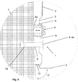
- Fig. 4 shows in detail that the compensation screw 6 comprises a threaded shaft 8 and insofar is connected with this threaded shaft 8 in a torque proof manner, wherein the threaded shaft 8 is received in a mating thread 9, which is connected with the base body 5.
- the mating thread 9 is realized in such a way that the surrounding contour of the cutout is configured in the form of at least one or two convolutions of the mating thread 9 in which the threaded shaft 8 of the compensation screw 6 is received.
- the surrounding contour of the cutout is configured in the form of at least one or two convolutions of the mating thread 9 in which the threaded shaft 8 of the compensation screw 6 is received.
- Fig. 1 to 4 show, that the base body 5 has a slot 10 with a mating thread 9 to receive the mounting screw 4.
- Fig. 1 to 4 show, that the base body 5 has a cutout 11, through which the compensation screw 6 protrudes in the direction of the wall 3, wherein the cutout 11 leads into the slot 10.
- the slot 10 and the cutout 11 are configured like a key hole, having only one opening.
- Fig. 1 to 5 show that the base body 5 is fixed to the rear panel 7.
- Fig. 2 shows with respect to a device 1', that the mounting screw 4 is located above the compensation screw 6.
- Fig. 1 to 4 show, that the mounting screw 4 has a hexagonal head 4a and may be fixed by a hex wrench.
- Fig. 5 show, that the rear panel 7, comprises a device 1 another device 1'.
- Fig. 1 to 5 show an arrangement, comprising an uneven wall 3 and a rear panel 7, wherein the compensation screw 6 is accessible and turnable in front of the front side of the rear panel 7 and wherein the compensation screw 6 protrudes with one end 6a to the wall 3 and lies against this wall 3, creating a gap or distance 13 between the back side of the rear panel 7 and the wall 3.
- Fig. 4 and 5 it is shown, that the wall 3 is uneven.
- Fig. 4 also shows, that the head 4a of the mounting screw 4 lies against the base body 5, wherein the mounting screw 4 rotatably protrudes with its thread in the direction of the wall 3 and wherein the base body 5 has a cutout 11, through which the compensation screw 6 protrudes in the direction of the wall 3.
- the mounting screw 4 mates with a thread 14 in the wall 3.
- Fig. 4 also shows, that the mounting screw 4 and the compensation screw 6 go through the rear panel 7 to reach the wall 3.
Landscapes
- Engineering & Computer Science (AREA)
- General Engineering & Computer Science (AREA)
- Power Engineering (AREA)
- Mechanical Engineering (AREA)
- Casings For Electric Apparatus (AREA)
Abstract
Description
- The invention is related to a device to mount a distribution cabinet to a wall, comprising at least one mounting screw, which is received in a base body and may be turned relatively to the base body.
- Currently, distribution cabinets often are arranged and fixed in front of and/or on a wall. Often the distribution cabinet is connected to this wall using mounting screws. Such screws protrude through the rear panel of the distribution cabinet and are driven into the wall to fix the distribution cabinet to this wall.
- The mounting screws are accessible from a front side of the distribution cabinet. When the mounting screws are tightened, a rear panel and/ or the cabinet may be deformed or distorted, if the wall is uneven or unequal.
- Currently, any user, especially an electrician, has problems to compensate an uneven wall, to which a distribution cabinet shall be connected. Often a user tries to compensate the unevenness with a homemade solution.
- The object of the invention therefore is to develop a distribution cabinet, whose position on and/or in front of a wall may be adjusted easily and accurately defined.
- The object of the invention is achieved by means of the features of
claim 1. - According to this claim the base body also comprises a compensation screw, which is received in the base body and may be turned relatively to the base body to create a gap or distance between a rear panel of the distribution cabinet and the wall. According to the invention it has been found that a distribution cabinet can be adjusted in its right position on and/or in front of a wall or a bottom wall. The distribution cabinet can be levelled using the device according to the invention. In the case of an uneven wall, the adjusting of the rear panel using a compensation screw gives the possibility to adjust the position of the cabinet as a whole. A levelling of the cabinet is possible. The invention is applicable for each type and number of mounting screws. Especially the device can be used, when only one mounting screw is used.
- Advantageously, the compensation screw is connected with a threaded shaft in a torque proof manner, wherein the threaded shaft is received in a mating thread, which is connected with the base body. Through this, the end of the compensation screw may be supported on or against the wall, while turning the compensation screw. This creates a counterforce, which moves the base body and the rear panel relatively to wall. The position of the rear panel may be adjusted.
- Advantageously, the compensation screw is made of or at least covered by an insulating material, such as a plastic material. The mounting screw may be configured as a standard metal screw.
- Further advantageously, the base body has a slot without a mating thread to receive the mounting screw. Through this, the mounting screw can mate with a thread in the wall or with a dowel in the wall and can draw and/ or press the rear panel against the wall.
- Advantageously, the base body has a cutout, through which the compensation screw may protrude in the direction of the wall, wherein the cutout leads into the slot or is neighboring the slot. The compensation screw and the mounting screw can be arranged in a space saving manner. The installation of the rear panel on the wall is simplified. The slot and the cutout preferably are configured like a key hole, having only one opening.
- Advantageously, the surrounding contour of the cutout is configured to form the mating thread in which the threaded shaft of the compensation screw is received. For this purpose, the surrounding contour of the cutout may be configured in the form of at least one or two convolutions of the mating thread in which the threaded shaft of the compensation screw is received. Configuring the surrounding contour of the cutout in the form of at least one or two convolutions of the mating thread is in the context of this invention regarded as an embodiment of connecting the mating thread with the base body.
- Further advantageously, the base body may be fixed by fixing means to a rear panel. The device may be arranged on different types of distribution cabinets. The fixing means may be screws. It is also possible, that the base body is integrated into the rear panel or that the rear panel or a part of the rear panel is the base body.
- Advantageously, the mounting screw is located above the compensation screw. The installation of the rear panel on the wall is simplified. The rear panel may be hinged on a mounting screw driven into the wall. The slot, which is closed on one side surrounds the mounting screw. The head of the mounting screw may easily pass the cutout of the compensation screw, which has a bigger diameter than the slot. The device acts as a loop or an eye and the mounting screw acts as a hook.
- Further, advantageously, the mounting screw has a hexagonal head and may be fixed by a hex wrench. A hex wrench is a common tool, which is easy to operate.
- Advantageously, a rear panel comprises a device as described here. Through this, a cabinet, especially an electric cabinet, may be adjusted being fixed to a wall.
- Further advantageously, an arrangement comprises a wall and a rear panel as described here, wherein the compensation screw is accessible and turnable in front of the front side of the rear panel and wherein the compensation screw protrudes with one end to the wall and lies against this wall creating a distance between the back side of the rear panel and the wall. The compensation screw may adjust the position of the rear panel relative to the wall. The mounting screw preferably is also accessible in front of the front side of the rear panel.
- Advantageously, the head of the mounting screw lies against the base body, wherein the mounting screw rotatably may protrude with its thread in the direction of the wall and wherein the base body has a cutout, through which the compensation screw may protrude in the direction of the wall. The rear panel may be fixed and adjusted in one step or two steps turning one screw or both said screws.
- Further advantageously, the mounting screw mates with a thread in the wall or a thread received in the wall. The rear panel may be reversibly fixed to the wall.
- Advantageously, the mounting screw and the compensation screw go through the rear panel to reach the wall. The rear panel may have holes or cutouts to receive the compensation screw and/ or the mounting screw. There is no need to drill any holes into the rear panel. Holes and cutouts are designed in a factory-provided manner.
- Preferably, the arrangement comprises a distribution cabinet or any other cabinet, which houses electrical components. It is possible, that more than one device is arranged on a rear panel or on any other panel or part of a panel, which is directed to a wall, which may be uneven. The mounting screw, pre-assembled in the wall, may be tightened, when the compensation screw has defined a correct position of the cabinet.
- In the drawings:
- Fig. 1
- shows a perspective view of a cabinet, comprising a device, having a compensation screw and a mounting screw, wherein the device is fixed on the front side of a rear panel and wherein the back side of the rear panel is directed to an uneven wall,
- Fig. 2
- shows a perspective view of a further cabinet, comprising a further device, having a compensation screw and a mounting screw, wherein the device is fixed on the front side of a rear panel, wherein the back side of the rear panel is directed to an uneven wall and wherein the mounting screw is located above the compensation screw,
- Fig. 3
- shows a perspective view of the cabinet according to
Fig. 1 , wherein the compensation screw is omitted, and - Fig. 4
- shows in detail the arrangement of
Fig. 1 in a sectional view according to the intersecting plane shown inFig. 1 and3 by a dashed line. - Fig. 5
- shows a side view of a cabinet, comprising a device with a mounting screw and compensation screw, wherein the device is used on the top and on the bottom from the cabinet, wherein the back side of the rear panel is directed to an uneven wall and wherein the mounting screw is located above the compensation screw,
-
Fig. 1 shows adevice 1 to mount adistribution cabinet 2 to awall 3, comprising a mounting screw 4, which is received in abase body 5 and which may be turned relatively to thebase body 5. Thebase body 5 also comprises acompensation screw 6, which is received in thebase body 5 and which may be turned relatively to thebase body 5 to create a gap ordistance 13 between arear panel 7 of thedistribution cabinet 2 and thewall 3. -
Fig. 4 shows in detail that thecompensation screw 6 comprises a threadedshaft 8 and insofar is connected with this threadedshaft 8 in a torque proof manner, wherein the threadedshaft 8 is received in amating thread 9, which is connected with thebase body 5. - The
mating thread 9 is realized in such a way that the surrounding contour of the cutout is configured in the form of at least one or two convolutions of themating thread 9 in which the threadedshaft 8 of thecompensation screw 6 is received. Of course one can think of other ways of connecting a mating thread with thebase body 5, too. -
Fig. 1 to 4 show, that thebase body 5 has aslot 10 with amating thread 9 to receive the mounting screw 4.Fig. 1 to 4 show, that thebase body 5 has acutout 11, through which thecompensation screw 6 protrudes in the direction of thewall 3, wherein thecutout 11 leads into theslot 10. Theslot 10 and thecutout 11 are configured like a key hole, having only one opening.Fig. 1 to 5 show that thebase body 5 is fixed to therear panel 7. -
Fig. 2 shows with respect to a device 1', that the mounting screw 4 is located above thecompensation screw 6.Fig. 1 to 4 show, that the mounting screw 4 has a hexagonal head 4a and may be fixed by a hex wrench. -
Fig. 5 show, that therear panel 7, comprises adevice 1 another device 1'. -
Fig. 1 to 5 show an arrangement, comprising anuneven wall 3 and arear panel 7, wherein thecompensation screw 6 is accessible and turnable in front of the front side of therear panel 7 and wherein thecompensation screw 6 protrudes with oneend 6a to thewall 3 and lies against thiswall 3, creating a gap ordistance 13 between the back side of therear panel 7 and thewall 3. - In
Fig. 4 and5 it is shown, that thewall 3 is uneven.Fig. 4 also shows, that the head 4a of the mounting screw 4 lies against thebase body 5, wherein the mounting screw 4 rotatably protrudes with its thread in the direction of thewall 3 and wherein thebase body 5 has acutout 11, through which thecompensation screw 6 protrudes in the direction of thewall 3. The mounting screw 4 mates with athread 14 in thewall 3.Fig. 4 also shows, that the mounting screw 4 and thecompensation screw 6 go through therear panel 7 to reach thewall 3.Reference numbers 1, 1' Device 2 Cabinet 3 Wall 4 Mounting screw 4a Head of 4 5 Base body of 1, 1' 6 Compensation screw 6a End of 6 7 Rear panel of 2 8 Threaded shaft 9 Mating thread of 5 10 Slot 11 Cutout 12 Tilt angle 13 Gap or distance between 2 and 3 14 Thread of 3
Claims (15)
- Device (1, 1') to mount a distribution cabinet (2) to a wall (3), comprising at least one mounting screw (4), which is received in a base body (5) and may be turned relatively to the base body (5),
characterized in that the base body (5) also comprises a compensation screw (6), which is received in the base body (5) and may be turned relatively to the base body (5) to create a gap or distance (13) between a rear panel (7) of the distribution cabinet (2) and the wall (3). - Device according to claim 1, characterized in that the compensation screw (6) is connected with a threaded shaft (8) in a torque proof manner, wherein the threaded shaft (8) is received in a mating thread (9), which is connected with the base body (5) in a torque proof manner.
- Device according to claim 1 or 2, characterized in that the base body (5) has a slot (10) without a mating thread to receive the mounting screw (4).
- Device according to claim 3, characterized in that the base body (5) has a cutout (11), through which the compensation screw (6) may protrude in the direction of the wall (3), wherein the cutout (11) leads into the slot (10) or is neighboring the slot (10).
- Device according to one of the preceding claims, characterized in that the base body (5) may be fixed to a rear panel (7).
- Device according to one of the preceding claims, characterized in that the mounting screw (4) is located above the compensation screw (6).
- Device according to one of the preceding claims, characterized in that the mounting screw (4) has a hexagonal head (4a) and may be fixed by a hex wrench.
- Rear panel (7), comprising a device (1, 1') according to one of the preceding claims.
- Arrangement, comprising a wall (3) and a rear panel (7) according to claim 8, wherein the compensation screw (6) is accessible and turnable in front of the front side of the rear panel (7) and wherein the compensation screw (6) protrudes with one end (6a) to the wall (3) and lies against this wall (3), creating a gap or distance (13) between the back side of the rear panel (7) and the wall (3).
- Arrangement according to claim 9, characterized in that the head (4a) of the mounting screw (4) lies against the base body (5), wherein the mounting screw (4) rotatably may protrude with its thread in the direction of the wall (3) and wherein the base body (5) has a cutout (11), through which the compensation screw (6) may protrude in the direction of the wall (3).
- Arrangement according to claim 9 or 10, characterized in that the mounting screw (4) mates with a thread (14) in the wall (3) or a thread (14) received in the wall (3).
- Arrangement according to one of the claims 9 to 11, characterized in that the mounting screw (4) and the compensation screw (6) go through the rear panel (7) to reach the wall (3).
- Arrangement according to one the claims 9 to 12, characterized in that the rear panel (7) is a rear panel (7) of a cabinet (2).
- Arrangement according to one the claims 9 to 13, characterized in that the rear panel (7) is a rear panel (7) of a distribution cabinet (2).
- Arrangement according to one the claims 9 to 14, characterized in that the rear panel (7) comprises several devices (1, 1').
Priority Applications (1)
| Application Number | Priority Date | Filing Date | Title |
|---|---|---|---|
| EP18206631.6A EP3654467B1 (en) | 2018-11-16 | 2018-11-16 | Wall mounting device for distribution cabinets |
Applications Claiming Priority (1)
| Application Number | Priority Date | Filing Date | Title |
|---|---|---|---|
| EP18206631.6A EP3654467B1 (en) | 2018-11-16 | 2018-11-16 | Wall mounting device for distribution cabinets |
Publications (2)
| Publication Number | Publication Date |
|---|---|
| EP3654467A1 true EP3654467A1 (en) | 2020-05-20 |
| EP3654467B1 EP3654467B1 (en) | 2022-05-11 |
Family
ID=64362332
Family Applications (1)
| Application Number | Title | Priority Date | Filing Date |
|---|---|---|---|
| EP18206631.6A Active EP3654467B1 (en) | 2018-11-16 | 2018-11-16 | Wall mounting device for distribution cabinets |
Country Status (1)
| Country | Link |
|---|---|
| EP (1) | EP3654467B1 (en) |
Citations (3)
| Publication number | Priority date | Publication date | Assignee | Title |
|---|---|---|---|---|
| JPS56129506A (en) * | 1980-03-10 | 1981-10-09 | Matsushita Electric Works Ltd | Device for mounting power distribution board |
| DE19859234A1 (en) * | 1998-05-09 | 1999-11-11 | Fischer Artur Werke Gmbh | Spacers |
| WO2013160186A1 (en) * | 2012-04-25 | 2013-10-31 | Arcelik Anonim Sirketi | Frame for mounting display devices on the wall |
-
2018
- 2018-11-16 EP EP18206631.6A patent/EP3654467B1/en active Active
Patent Citations (3)
| Publication number | Priority date | Publication date | Assignee | Title |
|---|---|---|---|---|
| JPS56129506A (en) * | 1980-03-10 | 1981-10-09 | Matsushita Electric Works Ltd | Device for mounting power distribution board |
| DE19859234A1 (en) * | 1998-05-09 | 1999-11-11 | Fischer Artur Werke Gmbh | Spacers |
| WO2013160186A1 (en) * | 2012-04-25 | 2013-10-31 | Arcelik Anonim Sirketi | Frame for mounting display devices on the wall |
Also Published As
| Publication number | Publication date |
|---|---|
| EP3654467B1 (en) | 2022-05-11 |
Similar Documents
| Publication | Publication Date | Title |
|---|---|---|
| US8076578B1 (en) | Adjustable electrical outlet box assembly | |
| US6964399B1 (en) | Appliance mounting device | |
| US7816604B1 (en) | Recessed low voltage mounting assembly | |
| US20160047151A1 (en) | Adjustable hinge | |
| US11512824B2 (en) | Panel light mounting structure, a panel light and mounting method thereof | |
| KR102372320B1 (en) | Height-adjustable wall-mounted stand fixing bracket | |
| US11898597B2 (en) | Flap bearing having an adjustment aid | |
| EP0400505A1 (en) | Integrated control device for a vehicle door and door fitted with this device | |
| CN102014699A (en) | Household appliance having a height adjusting device | |
| US10143104B2 (en) | Adaptive mounting rail and mounting assemblies for electronic devices | |
| CA3126559C (en) | Plumb adjuster for electrical enclosure | |
| EP3654467A1 (en) | Wall mounting device for distribution cabinets | |
| US20100213332A1 (en) | Cabinet leveling device | |
| US20190038021A1 (en) | Systems for quick mounting applied to a cabinet body | |
| US20210378402A1 (en) | Support stand and cabinet with support stand | |
| CN221722576U (en) | Hinge and cabinet | |
| US10986706B2 (en) | Microwave cooking oven with an adjusting device for adjusting a microwave shield | |
| US11202506B2 (en) | Support frame | |
| EP4358794B1 (en) | Supporting device for furniture | |
| EP3840148B1 (en) | Electrical device | |
| RU191741U1 (en) | RADIATOR MOUNT BRACKET | |
| KR200276770Y1 (en) | Console for Computer | |
| KR20060111211A (en) | Vertical hinge hinge device of refrigerator door | |
| JPH0328686Y2 (en) | ||
| EP1828515A1 (en) | Adjustable door hinge |
Legal Events
| Date | Code | Title | Description |
|---|---|---|---|
| PUAI | Public reference made under article 153(3) epc to a published international application that has entered the european phase |
Free format text: ORIGINAL CODE: 0009012 |
|
| STAA | Information on the status of an ep patent application or granted ep patent |
Free format text: STATUS: THE APPLICATION HAS BEEN PUBLISHED |
|
| AK | Designated contracting states |
Kind code of ref document: A1 Designated state(s): AL AT BE BG CH CY CZ DE DK EE ES FI FR GB GR HR HU IE IS IT LI LT LU LV MC MK MT NL NO PL PT RO RS SE SI SK SM TR |
|
| AX | Request for extension of the european patent |
Extension state: BA ME |
|
| STAA | Information on the status of an ep patent application or granted ep patent |
Free format text: STATUS: REQUEST FOR EXAMINATION WAS MADE |
|
| 17P | Request for examination filed |
Effective date: 20201104 |
|
| RBV | Designated contracting states (corrected) |
Designated state(s): AL AT BE BG CH CY CZ DE DK EE ES FI FR GB GR HR HU IE IS IT LI LT LU LV MC MK MT NL NO PL PT RO RS SE SI SK SM TR |
|
| GRAP | Despatch of communication of intention to grant a patent |
Free format text: ORIGINAL CODE: EPIDOSNIGR1 |
|
| STAA | Information on the status of an ep patent application or granted ep patent |
Free format text: STATUS: GRANT OF PATENT IS INTENDED |
|
| RIC1 | Information provided on ipc code assigned before grant |
Ipc: F16B 21/09 20060101ALN20211202BHEP Ipc: A47B 95/00 20060101ALN20211202BHEP Ipc: H02B 1/01 20060101ALN20211202BHEP Ipc: F16B 5/02 20060101ALI20211202BHEP Ipc: H02B 1/40 20060101AFI20211202BHEP |
|
| INTG | Intention to grant announced |
Effective date: 20211220 |
|
| GRAS | Grant fee paid |
Free format text: ORIGINAL CODE: EPIDOSNIGR3 |
|
| GRAA | (expected) grant |
Free format text: ORIGINAL CODE: 0009210 |
|
| STAA | Information on the status of an ep patent application or granted ep patent |
Free format text: STATUS: THE PATENT HAS BEEN GRANTED |
|
| RAP3 | Party data changed (applicant data changed or rights of an application transferred) |
Owner name: ABB SCHWEIZ AG |
|
| AK | Designated contracting states |
Kind code of ref document: B1 Designated state(s): AL AT BE BG CH CY CZ DE DK EE ES FI FR GB GR HR HU IE IS IT LI LT LU LV MC MK MT NL NO PL PT RO RS SE SI SK SM TR |
|
| REG | Reference to a national code |
Ref country code: GB Ref legal event code: FG4D |
|
| REG | Reference to a national code |
Ref country code: CH Ref legal event code: EP |
|
| REG | Reference to a national code |
Ref country code: AT Ref legal event code: REF Ref document number: 1492279 Country of ref document: AT Kind code of ref document: T Effective date: 20220515 |
|
| REG | Reference to a national code |
Ref country code: DE Ref legal event code: R096 Ref document number: 602018035336 Country of ref document: DE |
|
| REG | Reference to a national code |
Ref country code: IE Ref legal event code: FG4D |
|
| REG | Reference to a national code |
Ref country code: LT Ref legal event code: MG9D |
|
| REG | Reference to a national code |
Ref country code: NL Ref legal event code: MP Effective date: 20220511 |
|
| REG | Reference to a national code |
Ref country code: AT Ref legal event code: MK05 Ref document number: 1492279 Country of ref document: AT Kind code of ref document: T Effective date: 20220511 |
|
| PG25 | Lapsed in a contracting state [announced via postgrant information from national office to epo] |
Ref country code: SE Free format text: LAPSE BECAUSE OF FAILURE TO SUBMIT A TRANSLATION OF THE DESCRIPTION OR TO PAY THE FEE WITHIN THE PRESCRIBED TIME-LIMIT Effective date: 20220511 Ref country code: PT Free format text: LAPSE BECAUSE OF FAILURE TO SUBMIT A TRANSLATION OF THE DESCRIPTION OR TO PAY THE FEE WITHIN THE PRESCRIBED TIME-LIMIT Effective date: 20220912 Ref country code: NO Free format text: LAPSE BECAUSE OF FAILURE TO SUBMIT A TRANSLATION OF THE DESCRIPTION OR TO PAY THE FEE WITHIN THE PRESCRIBED TIME-LIMIT Effective date: 20220811 Ref country code: NL Free format text: LAPSE BECAUSE OF FAILURE TO SUBMIT A TRANSLATION OF THE DESCRIPTION OR TO PAY THE FEE WITHIN THE PRESCRIBED TIME-LIMIT Effective date: 20220511 Ref country code: LT Free format text: LAPSE BECAUSE OF FAILURE TO SUBMIT A TRANSLATION OF THE DESCRIPTION OR TO PAY THE FEE WITHIN THE PRESCRIBED TIME-LIMIT Effective date: 20220511 Ref country code: HR Free format text: LAPSE BECAUSE OF FAILURE TO SUBMIT A TRANSLATION OF THE DESCRIPTION OR TO PAY THE FEE WITHIN THE PRESCRIBED TIME-LIMIT Effective date: 20220511 Ref country code: GR Free format text: LAPSE BECAUSE OF FAILURE TO SUBMIT A TRANSLATION OF THE DESCRIPTION OR TO PAY THE FEE WITHIN THE PRESCRIBED TIME-LIMIT Effective date: 20220812 Ref country code: FI Free format text: LAPSE BECAUSE OF FAILURE TO SUBMIT A TRANSLATION OF THE DESCRIPTION OR TO PAY THE FEE WITHIN THE PRESCRIBED TIME-LIMIT Effective date: 20220511 Ref country code: ES Free format text: LAPSE BECAUSE OF FAILURE TO SUBMIT A TRANSLATION OF THE DESCRIPTION OR TO PAY THE FEE WITHIN THE PRESCRIBED TIME-LIMIT Effective date: 20220511 Ref country code: BG Free format text: LAPSE BECAUSE OF FAILURE TO SUBMIT A TRANSLATION OF THE DESCRIPTION OR TO PAY THE FEE WITHIN THE PRESCRIBED TIME-LIMIT Effective date: 20220811 Ref country code: AT Free format text: LAPSE BECAUSE OF FAILURE TO SUBMIT A TRANSLATION OF THE DESCRIPTION OR TO PAY THE FEE WITHIN THE PRESCRIBED TIME-LIMIT Effective date: 20220511 |
|
| PG25 | Lapsed in a contracting state [announced via postgrant information from national office to epo] |
Ref country code: RS Free format text: LAPSE BECAUSE OF FAILURE TO SUBMIT A TRANSLATION OF THE DESCRIPTION OR TO PAY THE FEE WITHIN THE PRESCRIBED TIME-LIMIT Effective date: 20220511 Ref country code: PL Free format text: LAPSE BECAUSE OF FAILURE TO SUBMIT A TRANSLATION OF THE DESCRIPTION OR TO PAY THE FEE WITHIN THE PRESCRIBED TIME-LIMIT Effective date: 20220511 Ref country code: LV Free format text: LAPSE BECAUSE OF FAILURE TO SUBMIT A TRANSLATION OF THE DESCRIPTION OR TO PAY THE FEE WITHIN THE PRESCRIBED TIME-LIMIT Effective date: 20220511 Ref country code: IS Free format text: LAPSE BECAUSE OF FAILURE TO SUBMIT A TRANSLATION OF THE DESCRIPTION OR TO PAY THE FEE WITHIN THE PRESCRIBED TIME-LIMIT Effective date: 20220911 |
|
| PG25 | Lapsed in a contracting state [announced via postgrant information from national office to epo] |
Ref country code: SM Free format text: LAPSE BECAUSE OF FAILURE TO SUBMIT A TRANSLATION OF THE DESCRIPTION OR TO PAY THE FEE WITHIN THE PRESCRIBED TIME-LIMIT Effective date: 20220511 Ref country code: SK Free format text: LAPSE BECAUSE OF FAILURE TO SUBMIT A TRANSLATION OF THE DESCRIPTION OR TO PAY THE FEE WITHIN THE PRESCRIBED TIME-LIMIT Effective date: 20220511 Ref country code: RO Free format text: LAPSE BECAUSE OF FAILURE TO SUBMIT A TRANSLATION OF THE DESCRIPTION OR TO PAY THE FEE WITHIN THE PRESCRIBED TIME-LIMIT Effective date: 20220511 Ref country code: EE Free format text: LAPSE BECAUSE OF FAILURE TO SUBMIT A TRANSLATION OF THE DESCRIPTION OR TO PAY THE FEE WITHIN THE PRESCRIBED TIME-LIMIT Effective date: 20220511 Ref country code: DK Free format text: LAPSE BECAUSE OF FAILURE TO SUBMIT A TRANSLATION OF THE DESCRIPTION OR TO PAY THE FEE WITHIN THE PRESCRIBED TIME-LIMIT Effective date: 20220511 Ref country code: CZ Free format text: LAPSE BECAUSE OF FAILURE TO SUBMIT A TRANSLATION OF THE DESCRIPTION OR TO PAY THE FEE WITHIN THE PRESCRIBED TIME-LIMIT Effective date: 20220511 |
|
| REG | Reference to a national code |
Ref country code: DE Ref legal event code: R097 Ref document number: 602018035336 Country of ref document: DE |
|
| PLBE | No opposition filed within time limit |
Free format text: ORIGINAL CODE: 0009261 |
|
| STAA | Information on the status of an ep patent application or granted ep patent |
Free format text: STATUS: NO OPPOSITION FILED WITHIN TIME LIMIT |
|
| PG25 | Lapsed in a contracting state [announced via postgrant information from national office to epo] |
Ref country code: AL Free format text: LAPSE BECAUSE OF FAILURE TO SUBMIT A TRANSLATION OF THE DESCRIPTION OR TO PAY THE FEE WITHIN THE PRESCRIBED TIME-LIMIT Effective date: 20220511 |
|
| 26N | No opposition filed |
Effective date: 20230214 |
|
| PG25 | Lapsed in a contracting state [announced via postgrant information from national office to epo] |
Ref country code: SI Free format text: LAPSE BECAUSE OF FAILURE TO SUBMIT A TRANSLATION OF THE DESCRIPTION OR TO PAY THE FEE WITHIN THE PRESCRIBED TIME-LIMIT Effective date: 20220511 |
|
| PG25 | Lapsed in a contracting state [announced via postgrant information from national office to epo] |
Ref country code: MC Free format text: LAPSE BECAUSE OF FAILURE TO SUBMIT A TRANSLATION OF THE DESCRIPTION OR TO PAY THE FEE WITHIN THE PRESCRIBED TIME-LIMIT Effective date: 20220511 |
|
| REG | Reference to a national code |
Ref country code: CH Ref legal event code: PL |
|
| GBPC | Gb: european patent ceased through non-payment of renewal fee |
Effective date: 20221116 |
|
| REG | Reference to a national code |
Ref country code: BE Ref legal event code: MM Effective date: 20221130 |
|
| PG25 | Lapsed in a contracting state [announced via postgrant information from national office to epo] |
Ref country code: LI Free format text: LAPSE BECAUSE OF NON-PAYMENT OF DUE FEES Effective date: 20221130 Ref country code: CH Free format text: LAPSE BECAUSE OF NON-PAYMENT OF DUE FEES Effective date: 20221130 |
|
| PG25 | Lapsed in a contracting state [announced via postgrant information from national office to epo] |
Ref country code: LU Free format text: LAPSE BECAUSE OF NON-PAYMENT OF DUE FEES Effective date: 20221116 |
|
| PG25 | Lapsed in a contracting state [announced via postgrant information from national office to epo] |
Ref country code: IE Free format text: LAPSE BECAUSE OF NON-PAYMENT OF DUE FEES Effective date: 20221116 Ref country code: GB Free format text: LAPSE BECAUSE OF NON-PAYMENT OF DUE FEES Effective date: 20221116 |
|
| PG25 | Lapsed in a contracting state [announced via postgrant information from national office to epo] |
Ref country code: FR Free format text: LAPSE BECAUSE OF NON-PAYMENT OF DUE FEES Effective date: 20221130 Ref country code: BE Free format text: LAPSE BECAUSE OF NON-PAYMENT OF DUE FEES Effective date: 20221130 |
|
| PG25 | Lapsed in a contracting state [announced via postgrant information from national office to epo] |
Ref country code: IT Free format text: LAPSE BECAUSE OF FAILURE TO SUBMIT A TRANSLATION OF THE DESCRIPTION OR TO PAY THE FEE WITHIN THE PRESCRIBED TIME-LIMIT Effective date: 20220511 |
|
| PG25 | Lapsed in a contracting state [announced via postgrant information from national office to epo] |
Ref country code: HU Free format text: LAPSE BECAUSE OF FAILURE TO SUBMIT A TRANSLATION OF THE DESCRIPTION OR TO PAY THE FEE WITHIN THE PRESCRIBED TIME-LIMIT; INVALID AB INITIO Effective date: 20181116 |
|
| PG25 | Lapsed in a contracting state [announced via postgrant information from national office to epo] |
Ref country code: CY Free format text: LAPSE BECAUSE OF FAILURE TO SUBMIT A TRANSLATION OF THE DESCRIPTION OR TO PAY THE FEE WITHIN THE PRESCRIBED TIME-LIMIT Effective date: 20220511 |
|
| PG25 | Lapsed in a contracting state [announced via postgrant information from national office to epo] |
Ref country code: MK Free format text: LAPSE BECAUSE OF FAILURE TO SUBMIT A TRANSLATION OF THE DESCRIPTION OR TO PAY THE FEE WITHIN THE PRESCRIBED TIME-LIMIT Effective date: 20220511 |
|
| PG25 | Lapsed in a contracting state [announced via postgrant information from national office to epo] |
Ref country code: MT Free format text: LAPSE BECAUSE OF FAILURE TO SUBMIT A TRANSLATION OF THE DESCRIPTION OR TO PAY THE FEE WITHIN THE PRESCRIBED TIME-LIMIT Effective date: 20220511 |
|
| PG25 | Lapsed in a contracting state [announced via postgrant information from national office to epo] |
Ref country code: BG Free format text: LAPSE BECAUSE OF FAILURE TO SUBMIT A TRANSLATION OF THE DESCRIPTION OR TO PAY THE FEE WITHIN THE PRESCRIBED TIME-LIMIT Effective date: 20220511 |
|
| PG25 | Lapsed in a contracting state [announced via postgrant information from national office to epo] |
Ref country code: BG Free format text: LAPSE BECAUSE OF FAILURE TO SUBMIT A TRANSLATION OF THE DESCRIPTION OR TO PAY THE FEE WITHIN THE PRESCRIBED TIME-LIMIT Effective date: 20220511 |
|
| REG | Reference to a national code |
Ref country code: DE Ref legal event code: R082 Ref document number: 602018035336 Country of ref document: DE Representative=s name: ZIMMERMANN & PARTNER PATENTANWAELTE MBB, DE |
|
| PG25 | Lapsed in a contracting state [announced via postgrant information from national office to epo] |
Ref country code: TR Free format text: LAPSE BECAUSE OF FAILURE TO SUBMIT A TRANSLATION OF THE DESCRIPTION OR TO PAY THE FEE WITHIN THE PRESCRIBED TIME-LIMIT Effective date: 20220511 |
|
| PGFP | Annual fee paid to national office [announced via postgrant information from national office to epo] |
Ref country code: DE Payment date: 20251119 Year of fee payment: 8 |