EP3654461B1 - L-band optical fiber amplifier with pumping balance - Google Patents
L-band optical fiber amplifier with pumping balance Download PDFInfo
- Publication number
- EP3654461B1 EP3654461B1 EP18248205.9A EP18248205A EP3654461B1 EP 3654461 B1 EP3654461 B1 EP 3654461B1 EP 18248205 A EP18248205 A EP 18248205A EP 3654461 B1 EP3654461 B1 EP 3654461B1
- Authority
- EP
- European Patent Office
- Prior art keywords
- pumping
- optical fiber
- erbium
- doped optical
- combiner
- Prior art date
- Legal status (The legal status is an assumption and is not a legal conclusion. Google has not performed a legal analysis and makes no representation as to the accuracy of the status listed.)
- Active
Links
Images

Classifications
-
- H—ELECTRICITY
- H01—ELECTRIC ELEMENTS
- H01S—DEVICES USING THE PROCESS OF LIGHT AMPLIFICATION BY STIMULATED EMISSION OF RADIATION [LASER] TO AMPLIFY OR GENERATE LIGHT; DEVICES USING STIMULATED EMISSION OF ELECTROMAGNETIC RADIATION IN WAVE RANGES OTHER THAN OPTICAL
- H01S3/00—Lasers, i.e. devices using stimulated emission of electromagnetic radiation in the infrared, visible or ultraviolet wave range
- H01S3/05—Construction or shape of optical resonators; Accommodation of active medium therein; Shape of active medium
- H01S3/06—Construction or shape of active medium
- H01S3/063—Waveguide lasers, i.e. whereby the dimensions of the waveguide are of the order of the light wavelength
- H01S3/067—Fibre lasers
- H01S3/06754—Fibre amplifiers
- H01S3/06787—Bidirectional amplifier
-
- H—ELECTRICITY
- H01—ELECTRIC ELEMENTS
- H01S—DEVICES USING THE PROCESS OF LIGHT AMPLIFICATION BY STIMULATED EMISSION OF RADIATION [LASER] TO AMPLIFY OR GENERATE LIGHT; DEVICES USING STIMULATED EMISSION OF ELECTROMAGNETIC RADIATION IN WAVE RANGES OTHER THAN OPTICAL
- H01S3/00—Lasers, i.e. devices using stimulated emission of electromagnetic radiation in the infrared, visible or ultraviolet wave range
- H01S3/05—Construction or shape of optical resonators; Accommodation of active medium therein; Shape of active medium
- H01S3/06—Construction or shape of active medium
- H01S3/063—Waveguide lasers, i.e. whereby the dimensions of the waveguide are of the order of the light wavelength
- H01S3/067—Fibre lasers
- H01S3/06754—Fibre amplifiers
-
- H—ELECTRICITY
- H01—ELECTRIC ELEMENTS
- H01S—DEVICES USING THE PROCESS OF LIGHT AMPLIFICATION BY STIMULATED EMISSION OF RADIATION [LASER] TO AMPLIFY OR GENERATE LIGHT; DEVICES USING STIMULATED EMISSION OF ELECTROMAGNETIC RADIATION IN WAVE RANGES OTHER THAN OPTICAL
- H01S3/00—Lasers, i.e. devices using stimulated emission of electromagnetic radiation in the infrared, visible or ultraviolet wave range
- H01S3/05—Construction or shape of optical resonators; Accommodation of active medium therein; Shape of active medium
- H01S3/06—Construction or shape of active medium
- H01S3/063—Waveguide lasers, i.e. whereby the dimensions of the waveguide are of the order of the light wavelength
- H01S3/067—Fibre lasers
- H01S3/06708—Constructional details of the fibre, e.g. compositions, cross-section, shape or tapering
- H01S3/06716—Fibre compositions or doping with active elements
-
- H—ELECTRICITY
- H01—ELECTRIC ELEMENTS
- H01S—DEVICES USING THE PROCESS OF LIGHT AMPLIFICATION BY STIMULATED EMISSION OF RADIATION [LASER] TO AMPLIFY OR GENERATE LIGHT; DEVICES USING STIMULATED EMISSION OF ELECTROMAGNETIC RADIATION IN WAVE RANGES OTHER THAN OPTICAL
- H01S3/00—Lasers, i.e. devices using stimulated emission of electromagnetic radiation in the infrared, visible or ultraviolet wave range
- H01S3/05—Construction or shape of optical resonators; Accommodation of active medium therein; Shape of active medium
- H01S3/06—Construction or shape of active medium
- H01S3/063—Waveguide lasers, i.e. whereby the dimensions of the waveguide are of the order of the light wavelength
- H01S3/067—Fibre lasers
- H01S3/06754—Fibre amplifiers
- H01S3/06758—Tandem amplifiers
-
- H—ELECTRICITY
- H01—ELECTRIC ELEMENTS
- H01S—DEVICES USING THE PROCESS OF LIGHT AMPLIFICATION BY STIMULATED EMISSION OF RADIATION [LASER] TO AMPLIFY OR GENERATE LIGHT; DEVICES USING STIMULATED EMISSION OF ELECTROMAGNETIC RADIATION IN WAVE RANGES OTHER THAN OPTICAL
- H01S3/00—Lasers, i.e. devices using stimulated emission of electromagnetic radiation in the infrared, visible or ultraviolet wave range
- H01S3/05—Construction or shape of optical resonators; Accommodation of active medium therein; Shape of active medium
- H01S3/06—Construction or shape of active medium
- H01S3/063—Waveguide lasers, i.e. whereby the dimensions of the waveguide are of the order of the light wavelength
- H01S3/067—Fibre lasers
- H01S3/06754—Fibre amplifiers
- H01S3/06762—Fibre amplifiers having a specific amplification band
- H01S3/0677—L-band amplifiers, i.e. amplification in the range of about 1560 nm to 1610 nm
-
- H—ELECTRICITY
- H01—ELECTRIC ELEMENTS
- H01S—DEVICES USING THE PROCESS OF LIGHT AMPLIFICATION BY STIMULATED EMISSION OF RADIATION [LASER] TO AMPLIFY OR GENERATE LIGHT; DEVICES USING STIMULATED EMISSION OF ELECTROMAGNETIC RADIATION IN WAVE RANGES OTHER THAN OPTICAL
- H01S3/00—Lasers, i.e. devices using stimulated emission of electromagnetic radiation in the infrared, visible or ultraviolet wave range
- H01S3/09—Processes or apparatus for excitation, e.g. pumping
- H01S3/091—Processes or apparatus for excitation, e.g. pumping using optical pumping
- H01S3/094—Processes or apparatus for excitation, e.g. pumping using optical pumping by coherent light
- H01S3/094003—Processes or apparatus for excitation, e.g. pumping using optical pumping by coherent light the pumped medium being a fibre
-
- H—ELECTRICITY
- H01—ELECTRIC ELEMENTS
- H01S—DEVICES USING THE PROCESS OF LIGHT AMPLIFICATION BY STIMULATED EMISSION OF RADIATION [LASER] TO AMPLIFY OR GENERATE LIGHT; DEVICES USING STIMULATED EMISSION OF ELECTROMAGNETIC RADIATION IN WAVE RANGES OTHER THAN OPTICAL
- H01S3/00—Lasers, i.e. devices using stimulated emission of electromagnetic radiation in the infrared, visible or ultraviolet wave range
- H01S3/09—Processes or apparatus for excitation, e.g. pumping
- H01S3/091—Processes or apparatus for excitation, e.g. pumping using optical pumping
- H01S3/094—Processes or apparatus for excitation, e.g. pumping using optical pumping by coherent light
- H01S3/094003—Processes or apparatus for excitation, e.g. pumping using optical pumping by coherent light the pumped medium being a fibre
- H01S3/094011—Processes or apparatus for excitation, e.g. pumping using optical pumping by coherent light the pumped medium being a fibre with bidirectional pumping, i.e. with injection of the pump light from both two ends of the fibre
-
- H—ELECTRICITY
- H01—ELECTRIC ELEMENTS
- H01S—DEVICES USING THE PROCESS OF LIGHT AMPLIFICATION BY STIMULATED EMISSION OF RADIATION [LASER] TO AMPLIFY OR GENERATE LIGHT; DEVICES USING STIMULATED EMISSION OF ELECTROMAGNETIC RADIATION IN WAVE RANGES OTHER THAN OPTICAL
- H01S3/00—Lasers, i.e. devices using stimulated emission of electromagnetic radiation in the infrared, visible or ultraviolet wave range
- H01S3/14—Lasers, i.e. devices using stimulated emission of electromagnetic radiation in the infrared, visible or ultraviolet wave range characterised by the material used as the active medium
- H01S3/16—Solid materials
- H01S3/1601—Solid materials characterised by an active (lasing) ion
- H01S3/1603—Solid materials characterised by an active (lasing) ion rare earth
- H01S3/1608—Solid materials characterised by an active (lasing) ion rare earth erbium
-
- H—ELECTRICITY
- H01—ELECTRIC ELEMENTS
- H01S—DEVICES USING THE PROCESS OF LIGHT AMPLIFICATION BY STIMULATED EMISSION OF RADIATION [LASER] TO AMPLIFY OR GENERATE LIGHT; DEVICES USING STIMULATED EMISSION OF ELECTROMAGNETIC RADIATION IN WAVE RANGES OTHER THAN OPTICAL
- H01S2301/00—Functional characteristics
- H01S2301/02—ASE (amplified spontaneous emission), noise; Reduction thereof
-
- H—ELECTRICITY
- H01—ELECTRIC ELEMENTS
- H01S—DEVICES USING THE PROCESS OF LIGHT AMPLIFICATION BY STIMULATED EMISSION OF RADIATION [LASER] TO AMPLIFY OR GENERATE LIGHT; DEVICES USING STIMULATED EMISSION OF ELECTROMAGNETIC RADIATION IN WAVE RANGES OTHER THAN OPTICAL
- H01S2301/00—Functional characteristics
- H01S2301/03—Suppression of nonlinear conversion, e.g. specific design to suppress for example stimulated brillouin scattering [SBS], mainly in optical fibres in combination with multimode pumping
-
- H—ELECTRICITY
- H01—ELECTRIC ELEMENTS
- H01S—DEVICES USING THE PROCESS OF LIGHT AMPLIFICATION BY STIMULATED EMISSION OF RADIATION [LASER] TO AMPLIFY OR GENERATE LIGHT; DEVICES USING STIMULATED EMISSION OF ELECTROMAGNETIC RADIATION IN WAVE RANGES OTHER THAN OPTICAL
- H01S2301/00—Functional characteristics
- H01S2301/04—Gain spectral shaping, flattening
-
- H—ELECTRICITY
- H01—ELECTRIC ELEMENTS
- H01S—DEVICES USING THE PROCESS OF LIGHT AMPLIFICATION BY STIMULATED EMISSION OF RADIATION [LASER] TO AMPLIFY OR GENERATE LIGHT; DEVICES USING STIMULATED EMISSION OF ELECTROMAGNETIC RADIATION IN WAVE RANGES OTHER THAN OPTICAL
- H01S3/00—Lasers, i.e. devices using stimulated emission of electromagnetic radiation in the infrared, visible or ultraviolet wave range
- H01S3/09—Processes or apparatus for excitation, e.g. pumping
- H01S3/091—Processes or apparatus for excitation, e.g. pumping using optical pumping
- H01S3/094—Processes or apparatus for excitation, e.g. pumping using optical pumping by coherent light
- H01S3/094061—Shared pump, i.e. pump light of a single pump source is used to pump plural gain media in parallel
-
- H—ELECTRICITY
- H01—ELECTRIC ELEMENTS
- H01S—DEVICES USING THE PROCESS OF LIGHT AMPLIFICATION BY STIMULATED EMISSION OF RADIATION [LASER] TO AMPLIFY OR GENERATE LIGHT; DEVICES USING STIMULATED EMISSION OF ELECTROMAGNETIC RADIATION IN WAVE RANGES OTHER THAN OPTICAL
- H01S3/00—Lasers, i.e. devices using stimulated emission of electromagnetic radiation in the infrared, visible or ultraviolet wave range
- H01S3/09—Processes or apparatus for excitation, e.g. pumping
- H01S3/091—Processes or apparatus for excitation, e.g. pumping using optical pumping
- H01S3/094—Processes or apparatus for excitation, e.g. pumping using optical pumping by coherent light
- H01S3/094096—Multi-wavelength pumping
-
- Y—GENERAL TAGGING OF NEW TECHNOLOGICAL DEVELOPMENTS; GENERAL TAGGING OF CROSS-SECTIONAL TECHNOLOGIES SPANNING OVER SEVERAL SECTIONS OF THE IPC; TECHNICAL SUBJECTS COVERED BY FORMER USPC CROSS-REFERENCE ART COLLECTIONS [XRACs] AND DIGESTS
- Y02—TECHNOLOGIES OR APPLICATIONS FOR MITIGATION OR ADAPTATION AGAINST CLIMATE CHANGE
- Y02D—CLIMATE CHANGE MITIGATION TECHNOLOGIES IN INFORMATION AND COMMUNICATION TECHNOLOGIES [ICT], I.E. INFORMATION AND COMMUNICATION TECHNOLOGIES AIMING AT THE REDUCTION OF THEIR OWN ENERGY USE
- Y02D30/00—Reducing energy consumption in communication networks
- Y02D30/70—Reducing energy consumption in communication networks in wireless communication networks
Definitions
- the present invention relates to the field of optical communication, and particularly to a balanced pumping L-band optical fiber amplifier.
- the over-lOOG system usually uses a dual-carrier or multi-carrier scheme with a modulation format of 8QAM or 16QAM, which has a low spectrum utilization.
- the conventional C-band (1528-1568nm) cannot meet the demand for bandwidth, and the demand of the system for L-band (1570-1610nm) becomes more and more urgent.
- An optical fiber amplifier usually includes an optical path structure implemented by two or three or more erbium -doped fibers.
- a conventional C-band fiber amplifier in general, all the optical fibers adopt forward pumping, or only the last optical fiber adopts backward pumping and other optical fibers adopt forward pumping.
- the erbium-doped optical fibers included in the L-band optical fiber amplifier have a length much longer than, usually 8-10 times of that in the C-band optical fiber amplifier, the conventional C-band optical path structure cannot be directly used in the L-band amplifier because it may cause some problems such as a high noise figure, a low conversion efficiency, and series non-linear four-wave mixing in the optical fibers.
- US 2005/122574 A1 discloses an optical amplification module comprising a WDM coupler, a EDF, a EDF, a EDF, and a WDM coupler arranged in this order, further comprising two pumping light sources respectively connected to the WDM couplers.
- the pumping light source provides forward pumping light to the EDF, EDF, and EDF through the WDM coupler, and the pumping light source provides backward pumping light to the EDF, EDF, and EDF through the WDM coupler.
- the EDF amplifies the signal light coming from the EDF, under supply of the pumping light from the WDM couplers.
- EP 1 128 503 A2 discloses a three-stages optical amplifier comprising a pre-amplifier stage, an intermediate amplifier stage and a power output amplifier stage which are optically coupled in cascade by means of a polarisation-state-insensitive circulator.
- Each of the three-stages includes a length of optically amplifying optical fiber unidirectionally pumped by the at least one optical pump.
- the optically amplifying optical fiber is injected with the pumping light from the optical pump for unidirectionally pumping.
- US 2005/111078 A1 discloses an optical amplifier including a first, second and third length of EDF, a noise suppression filter (NSF), and a pump laser.
- the first, second and third length of EDF, and the noise suppression filter 85 are arranged in this order, and the pump laser uni-directionally provides pumping light for three EDF.
- the NSF filters out ASE noise in at least one of the wavelength ranges.
- the document (“Enhancement of power conversion efficiency for an L-band EDFA with a secondary pumping effect in the unpumped EDF section", XP011425808) discloses an arrangement of L-band silica-based EDFA including a forward-pumped EDF section (EDF I), an unpumped EDF section (EDF II), a WDM coupler and a pump, where the EDF I, the WDM coupler, and the EDF II are connected in this order, and the pump is connected to the WDM coupler to provide pumping light to the EDF I.
- US 6 459 526 B1 discloses an L-band optical amplifier including a first stage erbium-doped fiber gain medium and a filter distributed over the first stage erbium-doped fiber gain medium, a source of pump power coupled to the first stage to provide pumping energy, wherein the filter is a continuous filter having two erbium doped cores, one of which is optically pumped to provide gain for the L-band signals and the other of which is unpumped to absorb the ASE light.
- US 5 995 277 A discloses a C-Band amplifier including a first amplification unit for amplifying an input signal light, using first pump light; an absorption unit for separating the signal light and the pump light from the output light of the first amplification unit and absorbing a light signal in a wavelength range; and a second amplification unit for amplifying the signal light output by the absorption unit, using second pump light.
- the L-band optical fiber amplifier includes a large length of erbium-doped optical fibers, when the conventional C-band optical path structure is directly applied in the L-band amplifier, it may cause problems such as a high noise figure, a low conversion efficiency, and series non-linear four-wave mixing in the optical fibers, and the manufacturing cost of the L-band optical fiber amplifier is high.
- the present invention achieves the goal by the following technical solution defined in appending independent claim 1.
- the present invention provides a balanced pumping L-band optical fiber amplifier comprising a first erbium-doped optical fiber 1-1, a second erbium-doped optical fiber 1-2, an absorbing erbium-doped optical fiber 1-3 and at least two pumping lasers, the first erbium-doped optical fiber 1-1, the second erbium-doped optical fiber 1-2 and the absorbing erbium-doped optical fiber 1-3 being sequentially arranged in this order, and the at least two pumping lasers providing pumping light to the first erbium-doped optical fiber (1-1) and the second erbium-doped optical fiber (1-2);
- the first erbium-doped optical fiber 1-1 is injected with forward pumping light and backward pumping light by the at least two pumping lasers
- the second erbium-doped optical fiber 1-2 is injected with forward pumping light and backward pumping light by the at least two pumping lasers
- the absorbing erbium-doped optical fiber 1-3 without pumping light injection is arranged downstream of the second erbium-doped optica fiber 1-2 to absorb amplified spontaneous emission (ASE) generated in the amplifier.
- ASE amplified spontaneous emission
- each pumping laser adopts an independent pumping mode or a splitting pumping mode to provide the pumping light for the erbium-doped optical fibers that need to be injected with the pumping light.
- the amplifier further comprises a first isolator 2-1, a first combiner 3-1, a second combiner 3-2, a third combiner 3-3, a fourth combiner 3-4, a second isolator 2-2 and a third isolator 2-3 connected sequentially in this order;
- first erbium-doped optical fiber 1-1 is connected between a common end of the first combiner 3-1 and a common end of the second combiner 3-2
- second erbium-doped optical fiber 1-2 is connected between a common end of the third combiner 3-3 and a common end of the fourth combiner 3-4
- the absorbing erbium-doped optical fiber 1-3 is connected between the second isolator 2-2 and the third isolator 2-3.
- the at least two pumping lasers comprise a first pumping laser 4-1 and a second pumping laser 4-2, and the optical fiber amplifier further comprises a first pumping beam splitter 5-1 and a second pumping beam splitter 5-2;
- first pumping laser 4-1 is connected with a common end of the first pumping beam splitter 5-1, a first splitting port of the first pumping beam splitter 5-1 is connected with a pumping end of the first combiner 3-1, and a second splitting port of the first pumping beam splitter 5-1 is connected with a pumping end of the third combiner 3-3, so that the first pumping laser 4-1 injects forward pumping light into the first erbium-doped optical fiber 1-1 and the second erbium-doped optical fiber 1-2 in a splitting pumping mode;
- the second pumping laser 4-2 is connected with a common end of the second pumping beam splitter 5-2, a first splitting port of the second pumping beam splitter 5-2 is connected with a pumping end of the fourth combiner 3-4, and a second splitting port of the second pumping beam splitter 5-2 is connected with a pumping end of the second combiner 3-2, so that the second pumping laser 4-2 injects backward pumping light into the second erbium-doped optical fiber 1-2 and the first erbium-doped optical fiber 1-1 in a splitting pumping mode.
- the amplifier further comprises a gain flatten filter 6 connected between a signal end of the second combiner 3-2 and a signal end of the third combiner 3-3, the gain flatten filter 6 itself has an integrated isolator.
- a fourth isolator 2-4 a variable optical attenuator 7, a fifth combiner 3-5 and a third erbium-doped optical fiber 1-4 sequentially connected in this order, and the third erbium-doped optical fiber 1-4 is connected with a common end of the fifth combiner 3-5.
- the at least two pumping lasers comprise a first pumping laser 4-1, a second pumping laser 4-2 and a third pumping laser 4-3, and the optical fiber amplifier further comprises a first pumping beam splitter 5-1 and a second pumping beam splitter 5-2;
- first pumping laser 4-1 is connected with a common end of the first pumping beam splitter 5-1, a first splitting port of the first pumping beam splitter 5-1 is connected with a pumping end of the first combiner 3-1, and a second splitting port of the first pumping beam splitter 5-1 is connected with a pumping end of the third combiner 3-3, so that the first pumping laser 4-1 injects forward pumping light into the first erbium-doped optical fiber 1-1 and the second erbium-doped optical fiber 1-2 in a splitting pumping mode;
- the second pumping laser 4-2 is connected with a common end of the second pumping beam splitter 5-2, a first splitting port of the second pumping beam splitter 5-2 is connected with a pumping end of the fourth combiner 3-4, and a second splitting port of the second pumping beam splitter 5-2 is connected with a pumping end of the second combiner 3-2, so that the second pumping laser 4-2 injects backward pumping light into the second erbium-doped optical fiber 1-2 and the first erbium-doped optical fiber 1-1 in a splitting pumping mode;
- the third pumping laser 4-3 is connected with a pumping end of the fifth combiner 3-5, so that the third pumping laser 4-3 injects forward pumping light into the third erbium-doped optical fiber 1-4 in an independent pumping mode.
- the at least two pumping lasers comprise a first pumping laser 4-1, a second pumping laser 4-2 and a third pumping laser 4-3, and the optical fiber amplifier further comprises a second pumping beam splitter 5-2 and a third pumping beam splitter 5-3;
- first pumping laser 4-1 is connected with a pumping end of the first combiner 3-1, so that the first pumping laser 4-1 injects forward pumping light into the first erbium-doped optical fiber 1-1 in an independent pumping mode;
- the second pumping laser 4-2 is connected with a common end of the second pumping beam splitter 5-2, a first splitting port of the second pumping beam splitter 5-2 is connected with a pumping end of the fourth combiner 3-4, and a second splitting port of the second pumping beam splitter 5-2 is connected with a pumping end of the second combiner 3-2, so that the second pumping laser 4-2 injects backward pumping light into the second erbium-doped optical fiber 1-2 and the first erbium-doped optical fiber 1-1 in a splitting pumping mode;
- the third pumping laser 4-3 is connected with a common end of the third pumping beam splitter 5-3, the first splitting port of the third pumping beam splitter 5-3 is connected with a pumping end of the fifth combiner 3-5, and a second splitting port of the third pumping beam splitter 5-3 is connected with a pumping end of the third combiner 3-3, so that the third pumping laser 4-3 injects forward pumping light into the third erbium-doped optical fiber 1-4 and the second erbium-doped optical fiber 1-2 in a splitting pumping mode.
- a splitting ratio of the first splitting port may be in a range from 70% to 90%, and a splitting ratio of the second splitting port may be in a range of 30% to 10%.
- the at least two pumping lasers generate pumping light with wavelength that satisfies the following conditions: wavelength of the backward pumping light ranges from 1460nm to 1490nm, wavelength of the forward pumping light ranges from 973nm to 982nm.
- the backward pumping is applied into the L-band amplifier, and bidirectional pumping is carried out in the first and last erbium-doped fibers that have the largest influence on the noise figure and the conversion efficiency in the optical path.
- a relatively short erbium-doped optical fiber that has no pumping injection is added to absorb the ASE.
- the problem that the L-band optical fiber amplifier has a high noise when utilizing backward pumping is solved, the pumping conversion efficiency is greatly improved, and the nonlinear four-wave mixing effect is reduced. Meanwhile, the noise figure of the amplifier is effectively reduced, and the manufacturing cost of the L-band optical fiber amplifier is also greatly reduced.
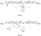
- FIGs. 1 and 2 show conventional C-band optical fiber amplifiers, which, as an example, each include two erbium-doped optical fibers arranged in the optical fiber amplifier.
- the two erbium-doped fibers both adopt forward pumping
- the last optical fiber adopts bidirectional pumping
- the first erbium-doped optical fiber adopts forward pumping.
- the last fiber does not have a significant influence on the noise figure and the non-linear four-wave mixing no matter it adopts forward, backward or bidirectional pumping; but for the L-band optical fiber amplifier, the pumping mode has a significant influence on the noise figure and the nonlinearity.
- the pumping mode has a significant influence on the noise figure and the nonlinearity.
- the conventional C-band optical path structure cannot be directly used in the L-band amplifier because it may cause some problems: when the L-band fiber amplifier adopts all forward pumping as shown in FIG. 1 , the conversion efficiency would be low, and the non-linear four-wave mixing would be serious; backward pumping will greatly increase the noise figure of the short wavelength in the L-band amplifier, and when the L-band amplifier has a low requirement on the noise figure, it can adopt the structure shown in FIG.
- the last erbium-doped optical fiber in the L-band amplifier cannot adopt backward pumping, and it is not appropriate for the L-band optical fiber amplifier to directly adopt the solution shown in FIG. 2 . Therefore, the conventinoal C-band optical path structure cannot be directly applied in the L-band amplifier, and certain optimization or improvement is still needed.
- the embodiment of the present invention provides a balanced pumping L-band optical fiber amplifier, as shown in FIGs. 3-5 , comprising a first erbium-doped optical fiber 1-1, a second erbium-doped optical fiber 1-2, an absorbing erbium-doped optical fiber 1-3 and at least two pumping lasers, the first erbium-doped optical fiber 1-1, the second erbium-doped optical fiber 1-2 and the absorbing erbium-doped optical fiber 1 -3 being sequentially arranged in this order, the at least two pumping lasers providing pumping light; wherein the first erbium-doped optical fiber 1-1 is injected with forward pumping light and backward pumping light by the at least two pumping lasers, the second erbium-doped optical fiber 1-2 is also injected with forward pumping light and backward pumping light by the at least two pumping lasers.
- the present invention additionally provides backward pumping, so that the two erbium-doped optical fibers both are bidirectional pumped.
- an erbium-doped optical fiber without pumping light injection i.e., the absorbing erbium-doped fiber 1-3, which is relatively shorter than the erbium-doped fibers with pumping light injection, is added downstream the second erbium-doped fiber 1-2 to absorb the amplified spontaneous emission (ASE) generated in the amplifier.
- ASE amplified spontaneous emission
- the optical fiber amplifier generally includes at least two erbium-doped optical fibers that need to be injected with the pumping light.
- the first erbium-doped optical fiber 1-1 is the first erbium-doped optical fiber in the optical path that needs to be injected with the pumping light
- the second erbium-doped optical fiber 1-2 is the last erbium-doped optical fiber in the optical path that needs to be injected with the pumping light.
- bidirectional pumping is adopted for each erbium-doped optical fiber except the absorbing erbium-doped optical fiber 1-3; in some other embodiments, preferably, bidirectional pumping is adopted for the first erbium-doped optical fiber 1-1 and the second erbium-doped optical fiber 1-2 while the other erbium-doped optical fibers adopts forward pumping.
- the backward pumping is successfully applied in the L-band amplifier by adopting bidirectional pumping for both the first and last erbium-doped optical fibers, and degradation of the short-wave noise figure caused thereby is improved through the relatively short erbium-doped optical fiber without pumping.
- the problem that the L-band optical fiber amplifier adopting the backward pumping has high noise is solved, the pumping conversion efficiency is greatly improved, and the non-linear four-wave mixing effect is reduced. Meanwhile, the noise figure of the amplifier is effectively reduced, and the manufacturing cost of the L-band optical fiber amplifier is greatly reduced.
- the L-band optical fiber amplifier may be a fixed gain amplifier (FGA) or a variable gain amplifier (VGA).
- FGA fixed gain amplifier
- VGA variable gain amplifier
- the at least two pumping lasers each, as a pumping light source may be in an independent pumping mode or a splitting pumping mode to inject pumping light into the erbium-doped fibers that need pumping.
- the independent pumping refers to that the pumping laser provides forward pumping light or backward pumping light for only a single erbium-doped fiber
- the splitting pumping refers to that the pumping laser provides forward pumping light or backward pumping light for two erbium-doped fibers simultaneously through beam splitting where the splitting ratio may be set according to actual needs.
- the pumping laser in the splitting pumping mode is taken as an example for describing the embodiments, but the invention is not limited thereto.
- the L-band optical fiber amplifier may be a FGA including two erbium-doped optical fibers that need to be injected with pumping light.
- the FGA may include a first isolator 2-1, a first combiner 3-1, a first erbium-doped optical fiber 1-1, a second combiner 3-2, a third combiner 3-3, a second erbium-doped optical fiber 1-2, a fourth combiner 3-4, a second isolator 2-2, an absorbing erbium-doped optical fiber 1-3 and a third isolator 2-3 connected sequentially in this order.
- the FGA may further include a gain flatten filter 6 connected between the second combiner 3-2 and the third combiner 3-3, and the gain flatten filter 6 itself may have an integrated isolator.
- the specific connection may be as follows: an input end of the amplifier is connected with an input end of the first isolator 2-1, an output end of the first isolator 2-1 is connected with a signal end of the first combiner 3-1, a common end of the first combiner 3-1 is connected with the first erbium-doped optical fiber 1-1, the first erbium-doped optical fiber 1-1 is further connected with a common end of the second combiner 3-2, a signal end of the second combiner 3-2 is connected with an input end of the gain flatten filter 6, an output end of the gain flatten filter 6 is connected with a signal end of the third combiner 3-3, a common end of the third combiner 3-3 is connected with the second erbium-doped optical fiber 1-2, the second erbium-doped optical fiber 1-2 is further connected with a common end of the fourth combiner 3-4, a signal end of the fourth combiner 3-4 is connected with an input end of the second isolator 2-2, an output end
- the at least two pumping lasers include a first pumping laser 4-1 for injecting forward pumping light into the first erbium-doped optical fiber 1-1 and the second erbium-doped optical fiber 1-2 in a splitting pumping mode, and a second pumping laser 4-2 for injecting backward pumping light into the second erbium-doped optical fiber 1-2 and the first erbium-doped optical fiber 1-1 in the splitting pumping mode.
- the FGA further includes a first pumping beam splitter 5-1 and a second pumping beam splitter 5-2
- the first pumping laser 4-1 is connected with a common end of the first pumping beam splitter 5-1
- a first splitting port of the first pumping beam splitter 5-1 is connected with an pumping end of the first combiner 3-1
- a second splitting port of the first pumping beam splitter 5-1 is connected with a pumping end of the third combiner 3-3
- the second pumping laser 4-2 is connected with a common end of the second pumping beam splitter 5-2
- a first splitting port of the second pumping beam splitter 5-2 is connected with a pumping end of the fourth combiner 3-4
- a second splitting port of the second pumping beam splitter 5-2 is connected with a pumping end of the second combiner 3-2.
- the present invention needs only two pumping lasers, so that not only is the cost saved, but also the overall performance of the amplifier in the splitting pumping mode, as proved by test, is improved, which will be described in detail later.
- the two erbium-doped fibers both are implemented by bidirectional pumping.
- pumping wavelengths may be the same as or different from each other.
- the wavelength of around 1480nm has a high conversion efficiency.
- the forward pumping is generally configured to be of a wavelength around 980nm
- the backward pumping is generally configured to be of a wavelength around 1480nm
- wavelength of the pumping light generated by the pumping laser satisfies the following conditions: the backward pumping light generated by the second pumping laser 4-2 has a wavelength in a range of 1460nm to 1490nm, and the forward pumping light generated by the first pumping laser 4-1 has a wavelength in a range of 973nm to 982nm.
- a splitting ratio of the first splitting port is larger than that of the corresponding second splitting port, and the splitting ratio of the first splitting port is in a range of 70% to 90%, the splitting ratio of the corresponding second splitting port is in a range of 30% to 10%.
- the splitting ratio of the first splitting port is 80%, and the splitting ratio of the second splitting port is 20%.
- the first pumping laser 4-1 mainly provides forward pumping light for the first erbium-doped optical fiber 1-1, and only a small part (i.e., 20%) of the forward pumping light is split our for the second erbium-doped optical fiber 1-2.
- the second pumping laser 4-2 mainly provides backward pumping light for the second erbium-doped optical fiber 1-2, and only a small part (i.e., 20%) is split out for the first erbium-doped optical fiber 1-1. By setting of the splitting ratio, the overall performance of the amplifier may be better optimized.
- the backward pumping is successfully applied into the L-band amplifier, thereby greatly improving the pumping conversion efficiency and reducing the non-linear four-wave mixing effect.
- the degradation of the short-wave noise figure which may be caused by application of the backward pumping in the L-band amplifier, may be improved through the relatively short erbium-doped optical fiber without pumping, and the noise figure of the amplifier is effectively reduced.
- G1 In order to decrease the overall noise figure NF, G1 needs to be increased and NF 1 needs to be reduced as much as possible.
- a general approach is to increase the injection power of the first erbium-doped optical fiber, but it has very little effect in the L-band amplifier due to the fact that in the L-band amplifier, the lengths of the erbium-doped optical fibers are relatively long in order to amplify the L-band signal, and when the pumping power injected into the first erbium-doped optical fiber continuously increases, the generated backward amplifier spontaneous emission (ASE) noise also continuously increases, and most of the energy added by pumping is converted into ASE.
- ASE backward amplifier spontaneous emission
- the present invention can greatly increase the gain and reduce the noise figure of the first erbium-doped optical fiber by applying bidirectional balanced pumping in the two erbium-doped optical fibers and additionally including the absorbing erbium-doped optical fiber without pumping injection, and thereby the overall noise figure is reduced.
- the specific structure of the fixed gain L-band amplifier FGA has been introduced in Embodiment 1, and on the basis of Embodiment 1, the specific structure of the variable gain L-band amplifier VGA will be introduced in this embodiment.
- the main difference from the FGA is that a variable optical attenuator (VOA) is added in the VGA.
- VOA variable optical attenuator
- the variable optical attenuator has a large insert loss, and the gain flatten filter has also a large loss at certain wavelength, the two elements will greatly influence the noise figure if they are placed together. Therefore, the two elements need to be arranged with different erbium-doped optical fibers.
- the VGA structure will have one more erbium-doped optical fiber than the FGA structure, and the one more erbium-doped optical fiber is noted as a third erbium-doped optical fiber 1-4.
- the third erbium-doped optical fiber 1-4 has little influence on the noise figure and the output power, so it may have bidirectional pumping injection or forward pumping injection, while the first and last erbium-doped optical fibers still adopt bidirectional pumping. Also, a relatively short erbium-doped optical fiber that has no pumping injection is added to absorb the ASE power.
- the positions of the VOA and the gain flatten filter can be exchanged to some extent, and in the present embodiment, as an example, the VOA is placed before the gain flatten filter.
- the specific structure of the VGA is as follows:
- a fourth isolator 2-4, a variable optical attenuator 7, a fifth combiner 3-5 and a third erbium-doped optical fiber 1-4 are additionally arranged between the second combiner 3-2 and the third combiner 3-3.
- the VGA comprises the first isolator 2-1, the first combiner 3-1, the first erbium-doped optical fiber 1-1, the second combiner 3-2, the fourth isolator 2-4, the variable optical attenuator 7, the fifth combiner 3-5, the third erbium-doped optical fiber 1-4, the gain flatten filter 6, the third combiner 3-3, the second erbium-doped optical fiber 1-2, the fourth combiner 3-4, the second isolator 2-2, the absorbing erbium-doped optical fiber 1-3 and the third isolator 2-3 sequentially connected in this order.
- the signal end of the second combiner 3-2 is connected with the input end of the fourth isolator 2-4
- the output end of the fourth isolator 2-4 is connected with the input end of the variable optical attenuator 7
- the output end of the variable optical attenuator 7 is connected with the signal end of the fifth combiner 3-5
- the common end of the fifth combiner 3-5 is connected with the third erbium-doped optical fiber 1-4
- the third erbium-doped optical fiber 1-4 is further connected with the input end of the gain flatten filter 6.
- the additionally arranged third erbium-doped optical fiber 1-4 may receive pumping light from a separate pumping laser as shown in FIG. 4 , or from a pumping laser in the splitting pumping mode as shown in FIG. 5 .
- the two different pumping modes will be described taking the third erbium-doped optical fiber 1-4 with forward pumping as an example:
- the at least two pumping lasers comprise the first pumping laser 4-1, the second pumping laser 4-2 and a third pumping laser 4-3.
- the first pumping laser 4-1 injects forward pumping light into the first erbium-doped optical fiber 1-1 and the second erbium-doped optical fiber 1-2 by splitting pumping
- the second pumping laser 4-2 injects backward pumping light into the second erbium-doped optical fiber 1-2 and the first erbium-doped optical fiber 1-1 by splitting pumping
- the third pumping laser 4-3 injects forward pumping light into the third erbium-doped optical fiber 1-4 by independent pumping.
- the specific implementation may be as follows:
- the VGA further comprises a first pumping beam splitter 5-1 and a second pumping beam splitter 5-2.
- the first pumping laser 4-1 is connected with a common end of the first pumping beam splitter 5-1, a first splitting port of the first pumping beam splitter 5-1 is connected with the pumping end of the first combiner 3-1, and a second splitting port of the first pumping beam splitter 5-1 is connected with the pumping end of the third combiner 3-3.
- the second pumping laser 4-2 is connected with a common end of the second pumping beam splitter 5-2, a first splitting port of the second pumping beam splitter 5-2 is connected with the pumping end of the fourth combiner 3-4, and a second splitting port of the second pumping beam splitter 5-2 is connected with the pumping end of the second combiner 3-2.
- the third pumping laser 4-3 is connected with the pumping end of the fifth combiner 3-5.
- the at least two pumping lasers comprise the first pumping laser 4-1, the second pumping laser 4-2 and the third pumping laser 4-3.
- the first pumping laser 4-1 injects forward pumping light into the first erbium-doped optical fiber 1-1 in the independent pumping mode
- the second pumping laser 4-2 injects backward pumping light into the second erbium-doped optical fiber 1-2 and the first erbium-doped optical fiber 1-1 in the splitting pumping mode
- the third pumping laser 4-3 injects forward pumping light into the third erbium-doped optical fiber 1-4 and the second erbium-doped optical fiber 1-2 in the splitting pumping mode.
- the specific implementation may be as follows:
- the VGA further comprises a second pumping beam splitter 5-2 and a third pumping beam splitter 5-3.
- the first pumping laser 4-1 is connected with the pumping end of the first combiner 3-1
- the second pumping laser 4-2 is connected with a common end of the second pumping beam splitter 5-2
- a first splitting port of the second pumping beam splitter 5-2 is connected with the pumping end of the fourth combiner 3-4
- a second splitting port of the second pumping beam splitter 5-2 is connected with the pumping end of the second combiner 3-2.
- the third pumping laser 4-3 is connected with a common end of the third pumping beam splitter 5-3, a first splitting port of the third pumping beam splitter 5-3 is connected with the pumping end of the fifth combiner 3-5, and a second splitting port of the third pumping beam splitter 5-3 is connected with the pumping end of the third combiner 3-3.
- the two VGA structures shown in FIG. 4 and FIG. 5 have the same main optical signal path, and the only difference is the way of injecting forward pumping light into each erbium-doped optical fiber.
- the present embodiment can save the cost, and the overall performance of the amplifier is better.
- the backward pumping light generated by the second pumping laser 4-2 has a wavelength in a range of 1460nm to 1490nm
- the forward pumping light generated by the first pumping laser 4-1 has a wavelength in a range of 973nm to 982nm.
- a splitting ratio of the first splitting port is larger than that of the corresponding second splitting port, and the splitting ratio of the first splitting port is in a range of 70% to 90%, the splitting ratio of the corresponding second splitting port is in a range of 30% to 10%.
- the splitting ratio of the first splitting port is 80%, and the splitting ratio of the second splitting port is 20%.
- the respective pumping modes are compared by experiments to demonstrate the overall performance of the optical fiber amplifiers provided by the present application.
- the optical path comprises two erbium-doped optical fibers that need to be injected with pumping light.
- a relationship between the noise figure and the pumping modes and a relationship between the non-linear four-wave mixing effect and the pumping modes are studied.
- the study shows that the overall performance of the optical fiber amplifier is optimal when the two erbium-doped optical fibers both adopt bidirectional pumping and the absorbing erbium-doped fiber is additionally provided.
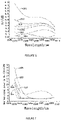
- FIG. 6 is a graph showing noise figure curves corresponding to different pumping modes with the same FGA gain and output power. With reference to the FGA structure diagram of FIG. 3 , the curves in FIG. 6 correspond to the following pumping modes:
- the pump1 represents the first pumping laser 4-1
- the pump2 represents the second pumping laser 4-2
- 80% and 20% represent the splitting ratio of the two splitting ports of the corresponding pumping beam splitter.
- the pumping mode corresponding to the curve 305 is the pumping mode used in the optical fiber amplifier of the present application. As can be seen from the figure, among all pumping modes, the curve 305 and the curve 306 has the lowest noise figer, especially when the wavelength is larger than 1578nm, the noise figure of the curve 305 reaches the minimal value.
- the erbium-doped fibers used in the double forward pumping of the curve 306 have a length of about 1.2 times of that in the pumping mode of the curve 305, and the pumping power of the pumping mode of the curve 306 is about 1.1 times of that of the curve 305.
- the cost of the double forward pumping mode corresponding to the curve 306 is obviously higher than that of the pumping mode of the curve 305.
- the maximum power of a single channel in the erbium-doped optical fiber is about 3 times of that in the pumping mode of the curve 305, causing much more series nonlinear effects such as the four-wave mixing effect, as shown in FIG. 7 .
- FIG. 7 is a graph showing a maximum power of a single channel in the erbium-doped optical fiber corresponding to different pumping modes. The larger the power is, the stronger the nonlinear effect in the amplifier is, and the overall performance of the amplifier is affected.
- the curves in FIG. 7 correspond to the following pumping modes:
- the pumping mode corresponding to the curve 403 is the pumping mode used in the optical fiber amplifier of the present application.
- the maximum power of the single channel in the erbium-doped optical fiber corresponding to the double forward pumping mode of the curve 401 is much higher than that corresponding to the other pumping modes of the other curves, causing a serious nonlinear effect such as the four-wave mixing effect, while the nonlinear effect is well controlled for the curve 403.
- the pumping mode in which the first erbium-doped optical fiber 1-1 is bidirectionally pumped (80% pump1 forward + 20% pump2 backward), the second erbium-doped optical fiber 1-2 is bidirectionally pumped (20% pump1 forward + 100% pump2 backward), and the absorbing erbium-doped optical fiber 1-3 of 1m has no pumping light injection can achieve an optimal noise figure, a relative low nonlinear effect, and a relative high pumping conversion efficiency, and the cost of the L-band optical fiber amplifier can be greatly reduced, thereby resulting in a high performance cost ratio.
Landscapes
- Physics & Mathematics (AREA)
- Electromagnetism (AREA)
- Engineering & Computer Science (AREA)
- Plasma & Fusion (AREA)
- Optics & Photonics (AREA)
- Lasers (AREA)
Description
- The present invention relates to the field of optical communication, and particularly to a balanced pumping L-band optical fiber amplifier.
- Along with the introduction of the "internet +" concept, the development of technologies such as 5G, cloud computing, big data, and internet of things (IoT) imposes higher demand on bandwidth and rate of the existing communication network. For either a data center or a conventional telecommunication network, a 100 Gbit/s system is widely used, and 200 Gbits/s and 400 Gbit/s systems are in a trial stage. The over-lOOG system usually uses a dual-carrier or multi-carrier scheme with a modulation format of 8QAM or 16QAM, which has a low spectrum utilization. The conventional C-band (1528-1568nm) cannot meet the demand for bandwidth, and the demand of the system for L-band (1570-1610nm) becomes more and more urgent.
- An optical fiber amplifier usually includes an optical path structure implemented by two or three or more erbium -doped fibers. In a conventional C-band fiber amplifier, in general, all the optical fibers adopt forward pumping, or only the last optical fiber adopts backward pumping and other optical fibers adopt forward pumping. As the erbium-doped optical fibers included in the L-band optical fiber amplifier have a length much longer than, usually 8-10 times of that in the C-band optical fiber amplifier, the conventional C-band optical path structure cannot be directly used in the L-band amplifier because it may cause some problems such as a high noise figure, a low conversion efficiency, and series non-linear four-wave mixing in the optical fibers. In addition, in the L-band fiber amplifier, power for pumping the first erbium-doped fiber needs to be greatly increased to reduce the noise figure, and power for pumping the last erbium doped fiber needs to be greatly increased to improve the output power, thereby causing a much higher cost and much lower performance than the C-band fiber amplifier.
- Therefore, there is an urgent need to overcome the above defects in the prior arts.
-
US 2005/122574 A1 discloses an optical amplification module comprising a WDM coupler, a EDF, a EDF, a EDF, and a WDM coupler arranged in this order, further comprising two pumping light sources respectively connected to the WDM couplers. The pumping light source provides forward pumping light to the EDF, EDF, and EDF through the WDM coupler, and the pumping light source provides backward pumping light to the EDF, EDF, and EDF through the WDM coupler. The EDF amplifies the signal light coming from the EDF, under supply of the pumping light from the WDM couplers. -
EP 1 128 503 A2 -
US 2005/111078 A1 discloses an optical amplifier including a first, second and third length of EDF, a noise suppression filter (NSF), and a pump laser. The first, second and third length of EDF, and the noise suppression filter 85 are arranged in this order, and the pump laser uni-directionally provides pumping light for three EDF. The NSF filters out ASE noise in at least one of the wavelength ranges. - The document ("Enhancement of power conversion efficiency for an L-band EDFA with a secondary pumping effect in the unpumped EDF section", XP011425808) discloses an arrangement of L-band silica-based EDFA including a forward-pumped EDF section (EDF I), an unpumped EDF section (EDF II), a WDM coupler and a pump, where the EDF I, the WDM coupler, and the EDF II are connected in this order, and the pump is connected to the WDM coupler to provide pumping light to the EDF I.
-
US 6 459 526 B1 discloses an L-band optical amplifier including a first stage erbium-doped fiber gain medium and a filter distributed over the first stage erbium-doped fiber gain medium, a source of pump power coupled to the first stage to provide pumping energy, wherein the filter is a continuous filter having two erbium doped cores, one of which is optically pumped to provide gain for the L-band signals and the other of which is unpumped to absorb the ASE light. -
US 5 995 277 A discloses a C-Band amplifier including a first amplification unit for amplifying an input signal light, using first pump light; an absorption unit for separating the signal light and the pump light from the output light of the first amplification unit and absorbing a light signal in a wavelength range; and a second amplification unit for amplifying the signal light output by the absorption unit, using second pump light. - The present invention is to solve a technical problem that:
- As the L-band optical fiber amplifier includes a large length of erbium-doped optical fibers, when the conventional C-band optical path structure is directly applied in the L-band amplifier, it may cause problems such as a high noise figure, a low conversion efficiency, and series non-linear four-wave mixing in the optical fibers, and the manufacturing cost of the L-band optical fiber amplifier is high.
- The present invention achieves the goal by the following technical solution defined in appending
independent claim 1. - Preferred embodiments of the present disclosure are provided as defined in the appended dependent claims. The present invention provides a balanced pumping L-band optical fiber amplifier comprising a first erbium-doped optical fiber 1-1, a second erbium-doped optical fiber 1-2, an absorbing erbium-doped optical fiber 1-3 and at least two pumping lasers, the first erbium-doped optical fiber 1-1, the second erbium-doped optical fiber 1-2 and the absorbing erbium-doped optical fiber 1-3 being sequentially arranged in this order, and the at least two pumping lasers providing pumping light to the first erbium-doped optical fiber (1-1) and the second erbium-doped optical fiber (1-2);
- Wherein the first erbium-doped optical fiber 1-1 is injected with forward pumping light and backward pumping light by the at least two pumping lasers, the second erbium-doped optical fiber 1-2 is injected with forward pumping light and backward pumping light by the at least two pumping lasers, and the absorbing erbium-doped optical fiber 1-3 without pumping light injection is arranged downstream of the second erbium-doped optica fiber 1-2 to absorb amplified spontaneous emission (ASE) generated in the amplifier.
- Preferably, each pumping laser adopts an independent pumping mode or a splitting pumping mode to provide the pumping light for the erbium-doped optical fibers that need to be injected with the pumping light.
- Preferably, the amplifier further comprises a first isolator 2-1, a first combiner 3-1, a second combiner 3-2, a third combiner 3-3, a fourth combiner 3-4, a second isolator 2-2 and a third isolator 2-3 connected sequentially in this order;
- Wherein the first erbium-doped optical fiber 1-1 is connected between a common end of the first combiner 3-1 and a common end of the second combiner 3-2, the second erbium-doped optical fiber 1-2 is connected between a common end of the third combiner 3-3 and a common end of the fourth combiner 3-4, and the absorbing erbium-doped optical fiber 1-3 is connected between the second isolator 2-2 and the third isolator 2-3.
- Preferably, the at least two pumping lasers comprise a first pumping laser 4-1 and a second pumping laser 4-2, and the optical fiber amplifier further comprises a first pumping beam splitter 5-1 and a second pumping beam splitter 5-2;
- Wherein the first pumping laser 4-1 is connected with a common end of the first pumping beam splitter 5-1, a first splitting port of the first pumping beam splitter 5-1 is connected with a pumping end of the first combiner 3-1, and a second splitting port of the first pumping beam splitter 5-1 is connected with a pumping end of the third combiner 3-3, so that the first pumping laser 4-1 injects forward pumping light into the first erbium-doped optical fiber 1-1 and the second erbium-doped optical fiber 1-2 in a splitting pumping mode;
- The second pumping laser 4-2 is connected with a common end of the second pumping beam splitter 5-2, a first splitting port of the second pumping beam splitter 5-2 is connected with a pumping end of the fourth combiner 3-4, and a second splitting port of the second pumping beam splitter 5-2 is connected with a pumping end of the second combiner 3-2, so that the second pumping laser 4-2 injects backward pumping light into the second erbium-doped optical fiber 1-2 and the first erbium-doped optical fiber 1-1 in a splitting pumping mode.
- Preferably, the amplifier further comprises a gain
flatten filter 6 connected between a signal end of the second combiner 3-2 and a signal end of the third combiner 3-3, the gainflatten filter 6 itself has an integrated isolator. - Preferably, between the second combiner 3-2 and the gain
flatten filter 6 are provided a fourth isolator 2-4, a variable optical attenuator 7, a fifth combiner 3-5 and a third erbium-doped optical fiber 1-4 sequentially connected in this order, and the third erbium-doped optical fiber 1-4 is connected with a common end of the fifth combiner 3-5. - Preferably, the at least two pumping lasers comprise a first pumping laser 4-1, a second pumping laser 4-2 and a third pumping laser 4-3, and the optical fiber amplifier further comprises a first pumping beam splitter 5-1 and a second pumping beam splitter 5-2;
- Wherein the first pumping laser 4-1 is connected with a common end of the first pumping beam splitter 5-1, a first splitting port of the first pumping beam splitter 5-1 is connected with a pumping end of the first combiner 3-1, and a second splitting port of the first pumping beam splitter 5-1 is connected with a pumping end of the third combiner 3-3, so that the first pumping laser 4-1 injects forward pumping light into the first erbium-doped optical fiber 1-1 and the second erbium-doped optical fiber 1-2 in a splitting pumping mode;
- The second pumping laser 4-2 is connected with a common end of the second pumping beam splitter 5-2, a first splitting port of the second pumping beam splitter 5-2 is connected with a pumping end of the fourth combiner 3-4, and a second splitting port of the second pumping beam splitter 5-2 is connected with a pumping end of the second combiner 3-2, so that the second pumping laser 4-2 injects backward pumping light into the second erbium-doped optical fiber 1-2 and the first erbium-doped optical fiber 1-1 in a splitting pumping mode;
- The third pumping laser 4-3 is connected with a pumping end of the fifth combiner 3-5, so that the third pumping laser 4-3 injects forward pumping light into the third erbium-doped optical fiber 1-4 in an independent pumping mode.
- Preferably, the at least two pumping lasers comprise a first pumping laser 4-1, a second pumping laser 4-2 and a third pumping laser 4-3, and the optical fiber amplifier further comprises a second pumping beam splitter 5-2 and a third pumping beam splitter 5-3;
- Wherein the first pumping laser 4-1 is connected with a pumping end of the first combiner 3-1, so that the first pumping laser 4-1 injects forward pumping light into the first erbium-doped optical fiber 1-1 in an independent pumping mode;
- The second pumping laser 4-2 is connected with a common end of the second pumping beam splitter 5-2, a first splitting port of the second pumping beam splitter 5-2 is connected with a pumping end of the fourth combiner 3-4, and a second splitting port of the second pumping beam splitter 5-2 is connected with a pumping end of the second combiner 3-2, so that the second pumping laser 4-2 injects backward pumping light into the second erbium-doped optical fiber 1-2 and the first erbium-doped optical fiber 1-1 in a splitting pumping mode;
- The third pumping laser 4-3 is connected with a common end of the third pumping beam splitter 5-3, the first splitting port of the third pumping beam splitter 5-3 is connected with a pumping end of the fifth combiner 3-5, and a second splitting port of the third pumping beam splitter 5-3 is connected with a pumping end of the third combiner 3-3, so that the third pumping laser 4-3 injects forward pumping light into the third erbium-doped optical fiber 1-4 and the second erbium-doped optical fiber 1-2 in a splitting pumping mode.
- Preferably, for any one of the pumping beam splitters, a splitting ratio of the first splitting port may be in a range from 70% to 90%, and a splitting ratio of the second splitting port may be in a range of 30% to 10%.
- Preferably, the at least two pumping lasers generate pumping light with wavelength that satisfies the following conditions: wavelength of the backward pumping light ranges from 1460nm to 1490nm, wavelength of the forward pumping light ranges from 973nm to 982nm.
- The present invention produces the following beneficial effects:
- According to the present invention, the backward pumping is applied into the L-band amplifier, and bidirectional pumping is carried out in the first and last erbium-doped fibers that have the largest influence on the noise figure and the conversion efficiency in the optical path. In addition to the erbium-doped optical fibers that are pumped, a relatively short erbium-doped optical fiber that has no pumping injection is added to absorb the ASE. Thus, the problem that the L-band optical fiber amplifier has a high noise when utilizing backward pumping is solved, the pumping conversion efficiency is greatly improved, and the nonlinear four-wave mixing effect is reduced. Meanwhile, the noise figure of the amplifier is effectively reduced, and the manufacturing cost of the L-band optical fiber amplifier is also greatly reduced.
- In order to more clearly illustrate the technical solutions of embodiments of the present invention, accompanying drawings showing examples of the embodiments will be briefly introduced below. Apparently, the accompanying drawings merely show some embodiments of the present invention, and persons of ordinary skill in the art will appreciate other drawings according to the accompanying drawings without creative efforts.
-
FIG. 1 is a schematic structural diagram showing an existing C-band optical fiber amplifier; -
FIG. 2 is a schematic structural diagram showing another existing C-band optical fiber amplifier; -
FIG. 3 is a schematic structural diagram showing a fixed gain balanced pumping L-band amplifier according to an embodiment of the present invention; -
FIG. 4 is a schematic structural diagram showing a variable gain balanced pumping L-band amplifier according to an embodiment of the present invention; -
FIG. 5 is a schematic structural diagram showing a variable gain balanced pumping L-band amplifier according to another embodiment of the present invention; -
FIG. 6 is a graph showing noise figures corresponding to different pumping modes under the same gain and output power conditions; -
FIG. 7 is a graph showing maximum signal power corresponding to different pumping modes under the same gain and output power conditions. - In order to make the goals, technical solutions and advantages of the present invention clear and apparent, the present invention will be further discussed in detail with reference to the accompanying drawings and the embodiments. It should be understood that the specific embodiments described herein are only used to explain the present invention but not to limit the present invention in any way.
- In the description of the present invention, the terms "in", "outside", "longitudinal", "lateral", "on", "below", "top", and "bottom" or the like are used to indicate orientation or position relationships based on the accompanying drawings for the sake of description of the present invention, but they do not require the present invention to be constructed and operated in the particular orientation or position relationships. Therefore, the terms should not be construed as limits on the present invention.
-
FIGs. 1 and 2 show conventional C-band optical fiber amplifiers, which, as an example, each include two erbium-doped optical fibers arranged in the optical fiber amplifier. InFIG. 1 , the two erbium-doped fibers both adopt forward pumping, while inFIG. 2 , the last optical fiber adopts bidirectional pumping, and the first erbium-doped optical fiber adopts forward pumping. For the C-band fiber amplifier, the last fiber does not have a significant influence on the noise figure and the non-linear four-wave mixing no matter it adopts forward, backward or bidirectional pumping; but for the L-band optical fiber amplifier, the pumping mode has a significant influence on the noise figure and the nonlinearity. Detailed analysis is as follows: - As the L-band optical fiber amplifier needs much longer erbium-doped optical fibers than the C-band optical fiber amplifier does, the conventional C-band optical path structure cannot be directly used in the L-band amplifier because it may cause some problems: when the L-band fiber amplifier adopts all forward pumping as shown in
FIG. 1 , the conversion efficiency would be low, and the non-linear four-wave mixing would be serious; backward pumping will greatly increase the noise figure of the short wavelength in the L-band amplifier, and when the L-band amplifier has a low requirement on the noise figure, it can adopt the structure shown inFIG. 2 , but when it has a high requirement on the noise figure, the last erbium-doped optical fiber in the L-band amplifier cannot adopt backward pumping, and it is not appropriate for the L-band optical fiber amplifier to directly adopt the solution shown inFIG. 2 . Therefore, the conventinoal C-band optical path structure cannot be directly applied in the L-band amplifier, and certain optimization or improvement is still needed. - The present invention will be discussed in detail with reference to the accompanying drawings and embodiments, where the technical features involved in the embodiments of the present invention described below can be combined with each other as long as there is no conflict between each other.
- The embodiment of the present invention provides a balanced pumping L-band optical fiber amplifier, as shown in
FIGs. 3-5 , comprising a first erbium-doped optical fiber 1-1, a second erbium-doped optical fiber 1-2, an absorbing erbium-doped optical fiber 1-3 and at least two pumping lasers, the first erbium-doped optical fiber 1-1, the second erbium-doped optical fiber 1-2 and the absorbing erbium-doped optical fiber 1 -3 being sequentially arranged in this order, the at least two pumping lasers providing pumping light; wherein the first erbium-doped optical fiber 1-1 is injected with forward pumping light and backward pumping light by the at least two pumping lasers, the second erbium-doped optical fiber 1-2 is also injected with forward pumping light and backward pumping light by the at least two pumping lasers. Compared with the existing double forward pumping, the present invention additionally provides backward pumping, so that the two erbium-doped optical fibers both are bidirectional pumped. In addition, an erbium-doped optical fiber without pumping light injection, i.e., the absorbing erbium-doped fiber 1-3, which is relatively shorter than the erbium-doped fibers with pumping light injection, is added downstream the second erbium-doped fiber 1-2 to absorb the amplified spontaneous emission (ASE) generated in the amplifier. - The optical fiber amplifier generally includes at least two erbium-doped optical fibers that need to be injected with the pumping light. According to the order of connection, the first erbium-doped optical fiber 1-1 is the first erbium-doped optical fiber in the optical path that needs to be injected with the pumping light, and the second erbium-doped optical fiber 1-2 is the last erbium-doped optical fiber in the optical path that needs to be injected with the pumping light. In some embodiments, preferably, bidirectional pumping is adopted for each erbium-doped optical fiber except the absorbing erbium-doped optical fiber 1-3; in some other embodiments, preferably, bidirectional pumping is adopted for the first erbium-doped optical fiber 1-1 and the second erbium-doped optical fiber 1-2 while the other erbium-doped optical fibers adopts forward pumping.
- In the balanced pumping L-band optical fiber amplifier of the embodiment, the backward pumping is successfully applied in the L-band amplifier by adopting bidirectional pumping for both the first and last erbium-doped optical fibers, and degradation of the short-wave noise figure caused thereby is improved through the relatively short erbium-doped optical fiber without pumping. Thus, the problem that the L-band optical fiber amplifier adopting the backward pumping has high noise is solved, the pumping conversion efficiency is greatly improved, and the non-linear four-wave mixing effect is reduced. Meanwhile, the noise figure of the amplifier is effectively reduced, and the manufacturing cost of the L-band optical fiber amplifier is greatly reduced.
- The L-band optical fiber amplifier may be a fixed gain amplifier (FGA) or a variable gain amplifier (VGA). No matter FGA or VGA, the at least two pumping lasers each, as a pumping light source, may be in an independent pumping mode or a splitting pumping mode to inject pumping light into the erbium-doped fibers that need pumping. The independent pumping refers to that the pumping laser provides forward pumping light or backward pumping light for only a single erbium-doped fiber, and the splitting pumping refers to that the pumping laser provides forward pumping light or backward pumping light for two erbium-doped fibers simultaneously through beam splitting where the splitting ratio may be set according to actual needs. In the following description, the pumping laser in the splitting pumping mode is taken as an example for describing the embodiments, but the invention is not limited thereto.
- As shown in
FIG. 3 , in an embodiment, the L-band optical fiber amplifier may be a FGA including two erbium-doped optical fibers that need to be injected with pumping light. The FGA may include a first isolator 2-1, a first combiner 3-1, a first erbium-doped optical fiber 1-1, a second combiner 3-2, a third combiner 3-3, a second erbium-doped optical fiber 1-2, a fourth combiner 3-4, a second isolator 2-2, an absorbing erbium-doped optical fiber 1-3 and a third isolator 2-3 connected sequentially in this order. In general, in order to achieve a flatten gain of the amplifier, the FGA may further include a gain flattenfilter 6 connected between the second combiner 3-2 and the third combiner 3-3, and the gain flattenfilter 6 itself may have an integrated isolator. - The specific connection may be as follows: an input end of the amplifier is connected with an input end of the first isolator 2-1, an output end of the first isolator 2-1 is connected with a signal end of the first combiner 3-1, a common end of the first combiner 3-1 is connected with the first erbium-doped optical fiber 1-1, the first erbium-doped optical fiber 1-1 is further connected with a common end of the second combiner 3-2, a signal end of the second combiner 3-2 is connected with an input end of the gain flatten filter 6, an output end of the gain flatten filter 6 is connected with a signal end of the third combiner 3-3, a common end of the third combiner 3-3 is connected with the second erbium-doped optical fiber 1-2, the second erbium-doped optical fiber 1-2 is further connected with a common end of the fourth combiner 3-4, a signal end of the fourth combiner 3-4 is connected with an input end of the second isolator 2-2, an output end of the second isolator 2-2 is connected with an input end of the absorbing erbium-doped optical fiber 1-3, an output end of the absorbing erbium-doped optical fiber 1-3 is connected with an input end of the third isolator 2-3, and an output end of the third isolator 2-3 is connected with an output end of the amplifier.
- With continued reference to
FIG. 3 , the at least two pumping lasers include a first pumping laser 4-1 for injecting forward pumping light into the first erbium-doped optical fiber 1-1 and the second erbium-doped optical fiber 1-2 in a splitting pumping mode, and a second pumping laser 4-2 for injecting backward pumping light into the second erbium-doped optical fiber 1-2 and the first erbium-doped optical fiber 1-1 in the splitting pumping mode. The specific implementation may be as follows: the FGA further includes a first pumping beam splitter 5-1 and a second pumping beam splitter 5-2, the first pumping laser 4-1 is connected with a common end of the first pumping beam splitter 5-1, a first splitting port of the first pumping beam splitter 5-1 is connected with an pumping end of the first combiner 3-1, and a second splitting port of the first pumping beam splitter 5-1 is connected with a pumping end of the third combiner 3-3; the second pumping laser 4-2 is connected with a common end of the second pumping beam splitter 5-2, a first splitting port of the second pumping beam splitter 5-2 is connected with a pumping end of the fourth combiner 3-4, and a second splitting port of the second pumping beam splitter 5-2 is connected with a pumping end of the second combiner 3-2. If independent pumping is applied, four pumping lasers are needed for bidirectional pumping of the first erbium-doped optical fiber 1-1 and the second erbium-doped optical fiber 1-2. By utilizing splitting pumping, the present invention needs only two pumping lasers, so that not only is the cost saved, but also the overall performance of the amplifier in the splitting pumping mode, as proved by test, is improved, which will be described in detail later. - In the above FGA structure, the two erbium-doped fibers both are implemented by bidirectional pumping. As each of the two erbium-doped fibers is relatively long, pumping wavelengths may be the same as or different from each other. For backward pumping, the wavelength of around 1480nm has a high conversion efficiency. In comprehensive consideration of cost and performance, the forward pumping is generally configured to be of a wavelength around 980nm, the backward pumping is generally configured to be of a wavelength around 1480nm, and wavelength of the pumping light generated by the pumping laser satisfies the following conditions: the backward pumping light generated by the second pumping laser 4-2 has a wavelength in a range of 1460nm to 1490nm, and the forward pumping light generated by the first pumping laser 4-1 has a wavelength in a range of 973nm to 982nm.
- In the embodiment, preferably, for any one of the pumping beam splitter, a splitting ratio of the first splitting port is larger than that of the corresponding second splitting port, and the splitting ratio of the first splitting port is in a range of 70% to 90%, the splitting ratio of the corresponding second splitting port is in a range of 30% to 10%. For example, in the present embodiment, the splitting ratio of the first splitting port is 80%, and the splitting ratio of the second splitting port is 20%. The first pumping laser 4-1 mainly provides forward pumping light for the first erbium-doped optical fiber 1-1, and only a small part (i.e., 20%) of the forward pumping light is split our for the second erbium-doped optical fiber 1-2. The second pumping laser 4-2 mainly provides backward pumping light for the second erbium-doped optical fiber 1-2, and only a small part (i.e., 20%) is split out for the first erbium-doped optical fiber 1-1. By setting of the splitting ratio, the overall performance of the amplifier may be better optimized.
- In the present embodiment, the backward pumping is successfully applied into the L-band amplifier, thereby greatly improving the pumping conversion efficiency and reducing the non-linear four-wave mixing effect. The degradation of the short-wave noise figure, which may be caused by application of the backward pumping in the L-band amplifier, may be improved through the relatively short erbium-doped optical fiber without pumping, and the noise figure of the amplifier is effectively reduced. In the L-band optical fiber amplifier, each erbium-doped optical fiber may be considered as an amplifier, and the whole may be considered as a cascade amplifier, of which an equivalent noise figure NF may be calculated according to a formula NF = NF1 + (NF2-1)/G1 where NF1 is the noise figure of the first erbium-doped optical fiber, and G1 is the gain of the last erbium-doped fiber. In order to decrease the overall noise figure NF, G1 needs to be increased and NF1 needs to be reduced as much as possible. For the C-band amplifier, a general approach is to increase the injection power of the first erbium-doped optical fiber, but it has very little effect in the L-band amplifier due to the fact that in the L-band amplifier, the lengths of the erbium-doped optical fibers are relatively long in order to amplify the L-band signal, and when the pumping power injected into the first erbium-doped optical fiber continuously increases, the generated backward amplifier spontaneous emission (ASE) noise also continuously increases, and most of the energy added by pumping is converted into ASE. The present invention can greatly increase the gain and reduce the noise figure of the first erbium-doped optical fiber by applying bidirectional balanced pumping in the two erbium-doped optical fibers and additionally including the absorbing erbium-doped optical fiber without pumping injection, and thereby the overall noise figure is reduced.
- The specific structure of the fixed gain L-band amplifier FGA has been introduced in
Embodiment 1, and on the basis ofEmbodiment 1, the specific structure of the variable gain L-band amplifier VGA will be introduced in this embodiment. The main difference from the FGA is that a variable optical attenuator (VOA) is added in the VGA. As the variable optical attenuator has a large insert loss, and the gain flatten filter has also a large loss at certain wavelength, the two elements will greatly influence the noise figure if they are placed together. Therefore, the two elements need to be arranged with different erbium-doped optical fibers. For this reason, the VGA structure will have one more erbium-doped optical fiber than the FGA structure, and the one more erbium-doped optical fiber is noted as a third erbium-doped optical fiber 1-4. The third erbium-doped optical fiber 1-4 has little influence on the noise figure and the output power, so it may have bidirectional pumping injection or forward pumping injection, while the first and last erbium-doped optical fibers still adopt bidirectional pumping. Also, a relatively short erbium-doped optical fiber that has no pumping injection is added to absorb the ASE power. The positions of the VOA and the gain flatten filter can be exchanged to some extent, and in the present embodiment, as an example, the VOA is placed before the gain flatten filter. The specific structure of the VGA is as follows: - As shown in
FIG. 4 and FIG. 5 , compared with the FGA structure inFIG. 3 , a fourth isolator 2-4, a variable optical attenuator 7, a fifth combiner 3-5 and a third erbium-doped optical fiber 1-4 are additionally arranged between the second combiner 3-2 and the third combiner 3-3. Thus, the VGA comprises the first isolator 2-1, the first combiner 3-1, the first erbium-doped optical fiber 1-1, the second combiner 3-2, the fourth isolator 2-4, the variable optical attenuator 7, the fifth combiner 3-5, the third erbium-doped optical fiber 1-4, the gain flattenfilter 6, the third combiner 3-3, the second erbium-doped optical fiber 1-2, the fourth combiner 3-4, the second isolator 2-2, the absorbing erbium-doped optical fiber 1-3 and the third isolator 2-3 sequentially connected in this order. The description in relation to theEmbodiment 1 may be referenced here for the specific connection, where the signal end of the second combiner 3-2 is connected with the input end of the fourth isolator 2-4, the output end of the fourth isolator 2-4 is connected with the input end of the variable optical attenuator 7, the output end of the variable optical attenuator 7 is connected with the signal end of the fifth combiner 3-5, the common end of the fifth combiner 3-5 is connected with the third erbium-doped optical fiber 1-4, and the third erbium-doped optical fiber 1-4 is further connected with the input end of the gain flattenfilter 6. - The additionally arranged third erbium-doped optical fiber 1-4 may receive pumping light from a separate pumping laser as shown in
FIG. 4 , or from a pumping laser in the splitting pumping mode as shown inFIG. 5 . The two different pumping modes will be described taking the third erbium-doped optical fiber 1-4 with forward pumping as an example: - In the first mode, referring to
FIG. 4 , the at least two pumping lasers comprise the first pumping laser 4-1, the second pumping laser 4-2 and a third pumping laser 4-3. The first pumping laser 4-1 injects forward pumping light into the first erbium-doped optical fiber 1-1 and the second erbium-doped optical fiber 1-2 by splitting pumping, the second pumping laser 4-2 injects backward pumping light into the second erbium-doped optical fiber 1-2 and the first erbium-doped optical fiber 1-1 by splitting pumping, and the third pumping laser 4-3 injects forward pumping light into the third erbium-doped optical fiber 1-4 by independent pumping. The specific implementation may be as follows: - The VGA further comprises a first pumping beam splitter 5-1 and a second pumping beam splitter 5-2. The first pumping laser 4-1 is connected with a common end of the first pumping beam splitter 5-1, a first splitting port of the first pumping beam splitter 5-1 is connected with the pumping end of the first combiner 3-1, and a second splitting port of the first pumping beam splitter 5-1 is connected with the pumping end of the third combiner 3-3. The second pumping laser 4-2 is connected with a common end of the second pumping beam splitter 5-2, a first splitting port of the second pumping beam splitter 5-2 is connected with the pumping end of the fourth combiner 3-4, and a second splitting port of the second pumping beam splitter 5-2 is connected with the pumping end of the second combiner 3-2. The third pumping laser 4-3 is connected with the pumping end of the fifth combiner 3-5.
- Second, referring to
FIG. 5 , the at least two pumping lasers comprise the first pumping laser 4-1, the second pumping laser 4-2 and the third pumping laser 4-3. The first pumping laser 4-1 injects forward pumping light into the first erbium-doped optical fiber 1-1 in the independent pumping mode, and the second pumping laser 4-2 injects backward pumping light into the second erbium-doped optical fiber 1-2 and the first erbium-doped optical fiber 1-1 in the splitting pumping mode, and the third pumping laser 4-3 injects forward pumping light into the third erbium-doped optical fiber 1-4 and the second erbium-doped optical fiber 1-2 in the splitting pumping mode. The specific implementation may be as follows: - The VGA further comprises a second pumping beam splitter 5-2 and a third pumping beam splitter 5-3. The first pumping laser 4-1 is connected with the pumping end of the first combiner 3-1, the second pumping laser 4-2 is connected with a common end of the second pumping beam splitter 5-2, a first splitting port of the second pumping beam splitter 5-2 is connected with the pumping end of the fourth combiner 3-4, and a second splitting port of the second pumping beam splitter 5-2 is connected with the pumping end of the second combiner 3-2. The third pumping laser 4-3 is connected with a common end of the third pumping beam splitter 5-3, a first splitting port of the third pumping beam splitter 5-3 is connected with the pumping end of the fifth combiner 3-5, and a second splitting port of the third pumping beam splitter 5-3 is connected with the pumping end of the third combiner 3-3.
- The two VGA structures shown in
FIG. 4 and FIG. 5 have the same main optical signal path, and the only difference is the way of injecting forward pumping light into each erbium-doped optical fiber. Compared with the case in which each erbium-doped optical fiber adopts the independent pumping, the present embodiment can save the cost, and the overall performance of the amplifier is better. Referring toEmbodiment 1, in comprehensive consideration of the cost and the performance, the backward pumping light generated by the second pumping laser 4-2 has a wavelength in a range of 1460nm to 1490nm, and the forward pumping light generated by the first pumping laser 4-1 has a wavelength in a range of 973nm to 982nm. - In the embodiment, preferably, for any one of the pumping beam splitter, a splitting ratio of the first splitting port is larger than that of the corresponding second splitting port, and the splitting ratio of the first splitting port is in a range of 70% to 90%, the splitting ratio of the corresponding second splitting port is in a range of 30% to 10%. For example, in the present embodiment, the splitting ratio of the first splitting port is 80%, and the splitting ratio of the second splitting port is 20%. By setting of the splitting ratio, the overall performance of the amplifier may be better optimized.
- In the present embodiment, the respective pumping modes are compared by experiments to demonstrate the overall performance of the optical fiber amplifiers provided by the present application. Specifically, taking the FGA provided in the
Embodiment 1 as an example, the optical path comprises two erbium-doped optical fibers that need to be injected with pumping light. Under the same gain and output power, a relationship between the noise figure and the pumping modes and a relationship between the non-linear four-wave mixing effect and the pumping modes are studied. The study shows that the overall performance of the optical fiber amplifier is optimal when the two erbium-doped optical fibers both adopt bidirectional pumping and the absorbing erbium-doped fiber is additionally provided. The detailed experiment results are as follows:
FIG. 6 is a graph showing noise figure curves corresponding to different pumping modes with the same FGA gain and output power. With reference to the FGA structure diagram ofFIG. 3 , the curves inFIG. 6 correspond to the following pumping modes: - 301: the first erbium-doped optical fiber 1-1 is forward-pumped, and the second erbium-doped optical fiber 1-2 is backward-pumped;
- 302: the first erbium-doped optical fiber 1-1 is bidirectionally pumped (100% pump1 forward + 20% pump2 backward), and the second erbium-doped optical fiber 1-2 is backward-pumped (80% pump2 backward);
- 303: the first erbium-doped optical fiber 1-1 is forward-pumped (80% pump1 forward), and the second erbium-doped optical fiber 1-2 is bidirectionally pumped (20% pump1 forward + 100% pump2 backward);
- 304: the first erbium-doped optical fiber 1-1 is bidirectionally pumped (80% pump1 forward and 20% pump2 backward), and the second erbium-doped optical fiber 1-2 is bidirectionally pumped (20% pump1 forward + 100% pump2 backward);
- 305: the first erbium-doped optical fiber 1-1 is bidirectionally pumped (80% pump1 forward and 20% pump2 backward), and the second erbium-doped optical fiber 1-2 is bidirectionally pumped (20% pump1 forward + 100% pump2 backward), the absorbing erbium-doped fiber 1-3 of 1m has no pumping light injection;
- 306: the first erbium-doped optical fiber 1-1 is forward pumped, and the second erbium-doped optical fiber 1-2 is forward pumped.
- The pump1 represents the first pumping laser 4-1, the pump2 represents the second pumping laser 4-2, and 80% and 20% represent the splitting ratio of the two splitting ports of the corresponding pumping beam splitter. The pumping mode corresponding to the
curve 305 is the pumping mode used in the optical fiber amplifier of the present application. As can be seen from the figure, among all pumping modes, thecurve 305 and thecurve 306 has the lowest noise figer, especially when the wavelength is larger than 1578nm, the noise figure of thecurve 305 reaches the minimal value. With the same gain and output power, the erbium-doped fibers used in the double forward pumping of thecurve 306 have a length of about 1.2 times of that in the pumping mode of thecurve 305, and the pumping power of the pumping mode of thecurve 306 is about 1.1 times of that of thecurve 305. As seen, the cost of the double forward pumping mode corresponding to thecurve 306 is obviously higher than that of the pumping mode of thecurve 305. Meanwhile, in the double forward pumping, the maximum power of a single channel in the erbium-doped optical fiber is about 3 times of that in the pumping mode of thecurve 305, causing much more series nonlinear effects such as the four-wave mixing effect, as shown inFIG. 7 . -
FIG. 7 is a graph showing a maximum power of a single channel in the erbium-doped optical fiber corresponding to different pumping modes. The larger the power is, the stronger the nonlinear effect in the amplifier is, and the overall performance of the amplifier is affected. The curves inFIG. 7 correspond to the following pumping modes: - 401: the first erbium-doped optical fiber 1-1 is forward pumped, and the second erbium-doped optical fiber 1-2 is forward pumped;
- 402: the first erbium-doped optical fiber 1-1 is bidirectionally pumped (80% pump1 forward + 20% pump2 backward), and the second erbium-doped optical fiber 1-2 is bidirectionally pumped (20% pump1 forward + 100% pump2 backward);
- 403: the first erbium-doped optical fiber 1-1 is bidirectionally pumped (80% pump1 forward + 20% pump2 backward), the second erbium-doped optical fiber 1-2 is bidirectionally pumped (20% pump1 forward + 100% pump2 backward), and the absorbing erbium-doped fiber 1-3 of 1m has no pumping light injection;
- 404: the first erbium-doped optical fiber 1-1 is bidirectionally pumped (100% pump1 forward + 20% pump2 backward), and the second erbium-doped optical fiber 1-2 is backward-pumped (80% pump2 backward);
- 405: the first erbium-doped optical fiber 1-1 is forward-pumped, and the second erbium-doped optical fiber 1-2 is backward pumped.
- The pumping mode corresponding to the
curve 403 is the pumping mode used in the optical fiber amplifier of the present application. As shown inFIG. 7 , the maximum power of the single channel in the erbium-doped optical fiber corresponding to the double forward pumping mode of thecurve 401 is much higher than that corresponding to the other pumping modes of the other curves, causing a serious nonlinear effect such as the four-wave mixing effect, while the nonlinear effect is well controlled for thecurve 403. - Therefore, in comprehensive consideration of factors such as the conversion efficiency, the noise figure and the nonlinear effect, the pumping mode in which the first erbium-doped optical fiber 1-1 is bidirectionally pumped (80% pump1 forward + 20% pump2 backward), the second erbium-doped optical fiber 1-2 is bidirectionally pumped (20% pump1 forward + 100% pump2 backward), and the absorbing erbium-doped optical fiber 1-3 of 1m has no pumping light injection, can achieve an optimal noise figure, a relative low nonlinear effect, and a relative high pumping conversion efficiency, and the cost of the L-band optical fiber amplifier can be greatly reduced, thereby resulting in a high performance cost ratio.
- The above described are only preferred embodiments of the present invention, and are not intended to limit the present invention.
Claims (10)
- A balanced pumping L-band optical fiber amplifier, characterized in comprising a first erbium-doped optical fiber (1-1), a second erbium-doped optical fiber (1-2), an absorbing erbium-doped optical fiber (1-3) and at least two pumping lasers, the first erbium-doped optical fiber (1-1), the second erbium-doped optical fiber (1-2) and the absorbing erbium-doped optical fiber (1-3) being sequentially arranged in this order, and the at least two pumping lasers providing pumping light to the first erbium-doped optical fiber (1-1) and the second erbium-doped optical fiber (1-2);
wherein the first erbium-doped optical fiber (1-1) is injected with forward pumping light and backward pumping light by the at least two pumping lasers, the second erbium-doped optical fiber (1-2) is injected with forward pumping light and backward pumping light by the at least two pumping lasers, and the absorbing erbium-doped optical fiber (1-3) without pumping light injection is arranged downstream of the second erbium-doped optical fiber (1-2) to absorb amplified spontaneous emission, ASE, generated in the amplifier. - The balanced pumping L-band optical fiber amplifier of claim 1, characterized in that each pumping laser adopts an independent pumping mode or a splitting pumping mode to provide the pumping light for the erbium-doped optical fibers that need to be injected with the pumping light.
- The balanced pumping L-band optical fiber amplifier of claim 1, characterized in further comprising a first isolator (2-1), a first combiner (3-1), a second combiner (3-2), a third combiner (3-3), a fourth combiner (3-4), a second isolator (2-2) and a third isolator (2-3) connected sequentially in this order,
wherein the first erbium-doped optical fiber (1-1) is connected between a common end of the first combiner (3-1) and a common end of the second combiner (3-2), the second erbium-doped optical fiber (1-2) is connected between a common end of the third combiner (3-3) and a common end of the fourth combiner (3-4), and the absorbing erbium-doped optical fiber (1-3) is connected between the second isolator (2-2) and the third isolator (2-3). - The balanced pumping L-band optical fiber amplifier of claim 3, characterized in that the at least two pumping lasers comprise a first pumping laser (4-1) and a second pumping laser (4-2), and the optical fiber amplifier further comprises a first pumping beam splitter (5-1) and a second pumping beam splitter (5-2),wherein the first pumping laser (4-1) is connected with a common end of the first pumping beam splitter (5-1), a first splitting port of the first pumping beam splitter (5-1) is connected with a pumping end of the first combiner (3-1), and a second splitting port of the first pumping beam splitter (5-1) is connected with a pumping end of the third combiner (3-3), so that the first pumping laser (4-1) injects the forward pumping light into the first erbium-doped optical fiber (1-1) and the second erbium-doped optical fiber (1-2) in the splitting pumping mode;the second pumping laser (4-2) is connected with a common end of the second pumping beam splitter (5-2), a first splitting port of the second pumping beam splitter (5-2) is connected with a pumping end of the fourth combiner (3-4), and a second splitting port of the second pumping beam splitter (5-2) is connected with a pumping end of the second combiner (3-2), so that the second pumping laser (4-2) injects the backward pumping light into the second erbium-doped optical fiber (1-2) and the first erbium-doped optical fiber (1-1) in the splitting pumping mode.
- The balanced pumping L-band optical fiber amplifier of claim 3, characterized in further comprising a gain flatten filter (6) connected between a signal end of the second combiner (3-2) and a signal end of the third combiner (3-3), the gain flatten filter (6) itself including an integrated isolator.
- The balanced pumping L-band optical fiber amplifier of claim 5, characterized in that between the second combiner (3-2) and the gain flatten filter (6) are further provided a fourth isolator (2-4), a variable optical attenuator (7), a fifth combiner (3-5) and a third erbium-doped optical fiber (1-4) sequentially connected in this order, and the third erbium-doped optical fiber (1-4) is connected with a common end of the fifth combiner (3-5).
- The balanced pumping L-band optical fiber amplifier of claim 6, characterized in that the at least two pumping lasers comprise a first pumping laser (4-1), a second pumping laser (4-2) and a third pumping laser (4-3), and the optical fiber amplifier further comprises a first pumping beam splitter (5-1) and a second pumping beam splitter (5-2);wherein the first pumping laser (4-1) is connected with a common end of the first pumping beam splitter (5-1), a first splitting port of the first pumping beam splitter (5-1) is connected with a pumping end of the first combiner (3-1), and a second splitting port of the first pumping beam splitter (5-1) is connected with a pumping end of the third combiner (3-3), so that the first pumping laser (4-1) injects the forward pumping light into the first erbium-doped optical fiber (1-1) and the second erbium-doped optical fiber (1-2) in the splitting pumping mode;the second pumping laser (4-2) is connected with a common end of the second pumping beam splitter (5-2), a first splitting port of the second pumping beam splitter (5-2) is connected with a pumping end of the fourth combiner (3-4), and a second splitting port of the second pumping beam splitter (5-2) is connected with a pumping end of the second combiner (3-2), so that the second pumping laser (4-2) injects the backward pumping light into the second erbium-doped optical fiber (1-2) and the first erbium-doped optical fiber (1-1) in the splitting pumping mode;the third pumping laser (4-3) is connected with a pumping end of the fifth combiner (3-5), so that the third pumping laser (4-3) injects the forward pumping light into the third erbium-doped optical fiber (1-4) in the independent pumping mode.
- The balanced pumping L-band optical fiber amplifier of claim 6, characterized in that the at least two pumping lasers comprise a first pumping laser (4-1), a second pumping laser (4-2) and a third pumping laser (4-3), and the optical fiber amplifier further comprises a second pumping beam splitter (5-2) and a third pumping beam splitter (5-3);wherein the first pumping laser (4-1) is connected with a pumping end of the first combiner (3-1), so that the first pumping laser (4-1) injects the forward pumping light into the first erbium-doped optical fiber (1-1) in the independent pumping mode;the second pumping laser (4-2) is connected with a common end of the second pumping beam splitter (5-2), a first splitting port of the second pumping beam splitter (5-2) is connected with a pumping end of the fourth combiner (3-4), and a second splitting port of the second pumping beam splitter (5-2) is connected with a pumping end of the second combiner (3-2), so that the second pumping laser (4-2) injects the backward pumping light into the second erbium-doped optical fiber (1-2) and the first erbium-doped optical fiber (1-1) in the splitting pumping mode;the third pumping laser (4-3) is connected with a common end of the third pumping beam splitter (5-3), the first splitting port of the third pumping beam splitter (5-3) is connected with a pumping end of the fifth combiner (3-5), and a second splitting port of the third pumping beam splitter (5-3) is connected with a pumping end of the third combiner (3-3), so that the third pumping laser (4-3) injects the forward pumping light into the third erbium-doped optical fiber (1-4) and the second erbium-doped optical fiber (1-2) in the splitting pumping mode.
- The balanced pumping L-band optical fiber amplifier of any one of claims 4, 7, 8, characterized in that in each of the pumping beam splitters, a splitting ratio of the first splitting port is in a range from 70% to 90%, and a splitting ratio of the second splitting port is in a range of 30% to 10%.
- The balanced pumping L-band optical fiber amplifier of any one of claims 1-9, characterized in that the at least two pumping lasers generate pumping light with wavelength that satisfies the following conditions: the wavelength of the backward pumping light ranges from 1460nm to 1490nm, and the wavelength of the forward pumping light ranges from 973nm to 982nm.
Applications Claiming Priority (1)
| Application Number | Priority Date | Filing Date | Title |
|---|---|---|---|
| CN201811347265.3A CN109473862A (en) | 2018-11-13 | 2018-11-13 | An Equalized Pumped L-band Fiber Amplifier |
Publications (2)
| Publication Number | Publication Date |
|---|---|
| EP3654461A1 EP3654461A1 (en) | 2020-05-20 |
| EP3654461B1 true EP3654461B1 (en) | 2022-11-16 |
Family
ID=65241097
Family Applications (1)
| Application Number | Title | Priority Date | Filing Date |
|---|---|---|---|
| EP18248205.9A Active EP3654461B1 (en) | 2018-11-13 | 2018-12-28 | L-band optical fiber amplifier with pumping balance |
Country Status (3)
| Country | Link |
|---|---|
| US (1) | US11245242B2 (en) |
| EP (1) | EP3654461B1 (en) |
| CN (2) | CN109473862A (en) |
Families Citing this family (9)
| Publication number | Priority date | Publication date | Assignee | Title |
|---|---|---|---|---|
| CN110571634B (en) * | 2019-08-12 | 2021-02-12 | 武汉光迅科技股份有限公司 | Optical signal output device and method, and storage medium |
| CN110661164A (en) * | 2019-08-23 | 2020-01-07 | 大族激光科技产业集团股份有限公司 | A Fiber Laser with Raman Light Threshold |
| CN110957627A (en) * | 2019-11-08 | 2020-04-03 | 北京工业大学 | High-power 2-micron intermediate infrared thulium-doped optical fiber picosecond laser |
| DE102020133142B4 (en) | 2019-12-13 | 2025-03-20 | Ii-Vi Delaware, Inc. | BLIND PUMP LASER DETECTION |
| CN112986663B (en) * | 2019-12-13 | 2025-03-14 | 福州高意通讯有限公司 | A detection structure and method for feedforward pump failure in L-band optical fiber amplifier |
| CN111698033B (en) * | 2020-05-21 | 2021-08-13 | 武汉光迅科技股份有限公司 | Hybrid fiber amplifier, optical signal amplification method, and optical communication system |
| CN112345060B (en) * | 2020-09-22 | 2022-10-11 | 上海波汇科技有限公司 | A DAS System Based on Remote Pump Amplifier |
| CN114006244A (en) * | 2021-09-30 | 2022-02-01 | 昂纳信息技术(深圳)有限公司 | Ultra-small hot-plug extension C-band ASE light source and optical module |
| CN120222122A (en) * | 2023-12-25 | 2025-06-27 | 华为技术有限公司 | Optical amplifiers and communication systems |
Citations (1)
| Publication number | Priority date | Publication date | Assignee | Title |
|---|---|---|---|---|
| US5995277A (en) * | 1997-06-30 | 1999-11-30 | Samsung Electronics Co., Ltd. | Optical fiber amplifier with absorber |
Family Cites Families (14)
| Publication number | Priority date | Publication date | Assignee | Title |
|---|---|---|---|---|
| JP2962248B2 (en) * | 1996-11-01 | 1999-10-12 | 日本電気株式会社 | Optical amplifier for wavelength multiplexed optical transmission |
| KR100280968B1 (en) * | 1997-12-10 | 2001-02-01 | 윤종용 | Optical fiber amplifier using a synchronized etal on filter |
| EP0989693A1 (en) * | 1998-09-22 | 2000-03-29 | PIRELLI CAVI E SISTEMI S.p.A. | Optical amplification system including an Erbium-Ytterbium co-doped fiber |
| US6459526B1 (en) * | 1999-08-09 | 2002-10-01 | Corning Incorporated | L band amplifier with distributed filtering |
| CA2326090A1 (en) * | 1999-12-13 | 2001-06-13 | Jds Uniphase Inc. | L-band optical amplifier |
| EP1128503A3 (en) * | 2000-02-28 | 2003-08-06 | Nortel Networks Limited | Optical amplifier stage |
| US6552844B2 (en) * | 2001-06-01 | 2003-04-22 | Agere Systems Guardian Corp. | Passively output flattened optical amplifier |
| US6954305B2 (en) * | 2001-09-26 | 2005-10-11 | Sumitomo Electric Industries, Ltd. | Optical amplifier and optical transmission system using it |
| JP4114715B2 (en) * | 2002-02-25 | 2008-07-09 | 独立行政法人産業技術総合研究所 | Noise reduction device for signal light and noise reduction method for signal light |
| CN1275362C (en) * | 2002-06-10 | 2006-09-13 | 中国科学技术大学 | High power ultrawide band ASE light source for C+L waveband |
| US7436583B2 (en) * | 2003-09-05 | 2008-10-14 | Sumitomo Electric Industries, Ltd. | Optical amplification fiber, optical amplifier module, optical communication system and optical amplifying method |
| US7324268B2 (en) * | 2003-11-21 | 2008-01-29 | Bti Photonic Systems Inc. | Optical signal amplifier and method |
| KR100594038B1 (en) * | 2003-12-19 | 2006-06-30 | 삼성전자주식회사 | El-band light source with high amplification efficiency and stable output |
| CN101132103A (en) * | 2007-08-23 | 2008-02-27 | 上海交通大学 | Single Longitudinal Mode Fiber Laser Based on Fabry-Perot Resonator |
-
2018
- 2018-11-13 CN CN201811347265.3A patent/CN109473862A/en active Pending
- 2018-11-13 CN CN202311567345.0A patent/CN117613648A/en active Pending
- 2018-12-21 US US16/230,305 patent/US11245242B2/en active Active
- 2018-12-28 EP EP18248205.9A patent/EP3654461B1/en active Active
Patent Citations (1)
| Publication number | Priority date | Publication date | Assignee | Title |
|---|---|---|---|---|
| US5995277A (en) * | 1997-06-30 | 1999-11-30 | Samsung Electronics Co., Ltd. | Optical fiber amplifier with absorber |
Also Published As
| Publication number | Publication date |
|---|---|
| US20200153191A1 (en) | 2020-05-14 |
| CN117613648A (en) | 2024-02-27 |
| US11245242B2 (en) | 2022-02-08 |
| EP3654461A1 (en) | 2020-05-20 |
| CN109473862A (en) | 2019-03-15 |
Similar Documents
| Publication | Publication Date | Title |
|---|---|---|
| US11245242B2 (en) | L-band optical fiber amplifier with pumping balance | |
| US5253104A (en) | Balanced optical amplifier | |
| US6747790B2 (en) | Optical amplifier for amplifying multi-wavelength light | |
| US6172803B1 (en) | Optical amplifier and transmission system using the same | |
| US6674570B2 (en) | Wide band erbium-doped fiber amplifier (EDFA) | |
| US5831754A (en) | Optical amplifier | |
| US7085039B2 (en) | Hybrid Raman/erbium-doped fiber amplifier and transmission system with dispersion map | |
| US6657774B1 (en) | Amplifier system with distributed and discrete Raman fiber amplifiers | |
| KR100334778B1 (en) | Long band fiber amplifier using feedback loop | |
| JP6312927B2 (en) | Optical repeater and optical fiber communication system | |
| CN117913634A (en) | EDFA with adjustable output power and noise factor and corresponding control method and system | |
| EP1788731B1 (en) | Optical transmission system and optical filter assembly for submarine applications | |
| EP1087474A2 (en) | High power, multi-stage doped optical amplifier | |
| KR20030069362A (en) | Dispersion-compensated raman optical fiber amplifier | |
| US11349275B2 (en) | Complementary optical fiber-based amplifiers with built-in gain flattening | |
| Maeda et al. | Propagation direction interleaved cladding pumped 19-core EDFA in L-band | |
| US11764536B2 (en) | Optical amplifier for multiple bands | |
| JP2005522886A (en) | Optical amplifier | |
| KR0183913B1 (en) | Erbium-doped fiber amplifier with flat high gain and low noise figure | |
| KR0183911B1 (en) | Optical fiber amplifier having flat gain and low noise-figure | |
| WO2026045195A1 (en) | Optical amplifier and optical communication system | |
| WO2026001447A1 (en) | Optical fiber amplifier | |
| CN121395021A (en) | C+L wave band optical fiber amplifying module and optical fiber laser | |
| Izyani et al. | Flattened dual-stage GC-EDFA using fiber-ring laser technique | |
| JP2007288124A (en) | Optical fiber amplifier |
Legal Events
| Date | Code | Title | Description |
|---|---|---|---|
| PUAI | Public reference made under article 153(3) epc to a published international application that has entered the european phase |
Free format text: ORIGINAL CODE: 0009012 |
|
| STAA | Information on the status of an ep patent application or granted ep patent |
Free format text: STATUS: THE APPLICATION HAS BEEN PUBLISHED |
|
| AK | Designated contracting states |
Kind code of ref document: A1 Designated state(s): AL AT BE BG CH CY CZ DE DK EE ES FI FR GB GR HR HU IE IS IT LI LT LU LV MC MK MT NL NO PL PT RO RS SE SI SK SM TR |
|
| AX | Request for extension of the european patent |
Extension state: BA ME |
|
| STAA | Information on the status of an ep patent application or granted ep patent |
Free format text: STATUS: REQUEST FOR EXAMINATION WAS MADE |
|
| 17P | Request for examination filed |
Effective date: 20201014 |
|
| RBV | Designated contracting states (corrected) |
Designated state(s): AL AT BE BG CH CY CZ DE DK EE ES FI FR GB GR HR HU IE IS IT LI LT LU LV MC MK MT NL NO PL PT RO RS SE SI SK SM TR |
|
| RIC1 | Information provided on ipc code assigned before grant |
Ipc: H01S 3/16 20060101ALI20220511BHEP Ipc: H01S 3/094 20060101ALI20220511BHEP Ipc: H01S 3/067 20060101AFI20220511BHEP |
|
| GRAP | Despatch of communication of intention to grant a patent |
Free format text: ORIGINAL CODE: EPIDOSNIGR1 |
|
| STAA | Information on the status of an ep patent application or granted ep patent |
Free format text: STATUS: GRANT OF PATENT IS INTENDED |
|
| INTG | Intention to grant announced |
Effective date: 20220627 |
|
| GRAS | Grant fee paid |
Free format text: ORIGINAL CODE: EPIDOSNIGR3 |
|
| GRAA | (expected) grant |
Free format text: ORIGINAL CODE: 0009210 |
|
| STAA | Information on the status of an ep patent application or granted ep patent |
Free format text: STATUS: THE PATENT HAS BEEN GRANTED |
|
| AK | Designated contracting states |
Kind code of ref document: B1 Designated state(s): AL AT BE BG CH CY CZ DE DK EE ES FI FR GB GR HR HU IE IS IT LI LT LU LV MC MK MT NL NO PL PT RO RS SE SI SK SM TR |
|
| REG | Reference to a national code |
Ref country code: GB Ref legal event code: FG4D |
|
| REG | Reference to a national code |
Ref country code: CH Ref legal event code: EP |
|
| REG | Reference to a national code |
Ref country code: IE Ref legal event code: FG4D |
|
| REG | Reference to a national code |
Ref country code: DE Ref legal event code: R096 Ref document number: 602018043084 Country of ref document: DE |
|
| REG | Reference to a national code |
Ref country code: AT Ref legal event code: REF Ref document number: 1532344 Country of ref document: AT Kind code of ref document: T Effective date: 20221215 |
|
| REG | Reference to a national code |
Ref country code: LT Ref legal event code: MG9D |
|
| REG | Reference to a national code |
Ref country code: NL Ref legal event code: MP Effective date: 20221116 |
|
| REG | Reference to a national code |
Ref country code: AT Ref legal event code: MK05 Ref document number: 1532344 Country of ref document: AT Kind code of ref document: T Effective date: 20221116 |
|
| PG25 | Lapsed in a contracting state [announced via postgrant information from national office to epo] |
Ref country code: SE Free format text: LAPSE BECAUSE OF FAILURE TO SUBMIT A TRANSLATION OF THE DESCRIPTION OR TO PAY THE FEE WITHIN THE PRESCRIBED TIME-LIMIT Effective date: 20221116 Ref country code: PT Free format text: LAPSE BECAUSE OF FAILURE TO SUBMIT A TRANSLATION OF THE DESCRIPTION OR TO PAY THE FEE WITHIN THE PRESCRIBED TIME-LIMIT Effective date: 20230316 Ref country code: NO Free format text: LAPSE BECAUSE OF FAILURE TO SUBMIT A TRANSLATION OF THE DESCRIPTION OR TO PAY THE FEE WITHIN THE PRESCRIBED TIME-LIMIT Effective date: 20230216 Ref country code: LT Free format text: LAPSE BECAUSE OF FAILURE TO SUBMIT A TRANSLATION OF THE DESCRIPTION OR TO PAY THE FEE WITHIN THE PRESCRIBED TIME-LIMIT Effective date: 20221116 Ref country code: FI Free format text: LAPSE BECAUSE OF FAILURE TO SUBMIT A TRANSLATION OF THE DESCRIPTION OR TO PAY THE FEE WITHIN THE PRESCRIBED TIME-LIMIT Effective date: 20221116 Ref country code: ES Free format text: LAPSE BECAUSE OF FAILURE TO SUBMIT A TRANSLATION OF THE DESCRIPTION OR TO PAY THE FEE WITHIN THE PRESCRIBED TIME-LIMIT Effective date: 20221116 Ref country code: AT Free format text: LAPSE BECAUSE OF FAILURE TO SUBMIT A TRANSLATION OF THE DESCRIPTION OR TO PAY THE FEE WITHIN THE PRESCRIBED TIME-LIMIT Effective date: 20221116 |
|
| PG25 | Lapsed in a contracting state [announced via postgrant information from national office to epo] |
Ref country code: RS Free format text: LAPSE BECAUSE OF FAILURE TO SUBMIT A TRANSLATION OF THE DESCRIPTION OR TO PAY THE FEE WITHIN THE PRESCRIBED TIME-LIMIT Effective date: 20221116 Ref country code: PL Free format text: LAPSE BECAUSE OF FAILURE TO SUBMIT A TRANSLATION OF THE DESCRIPTION OR TO PAY THE FEE WITHIN THE PRESCRIBED TIME-LIMIT Effective date: 20221116 Ref country code: LV Free format text: LAPSE BECAUSE OF FAILURE TO SUBMIT A TRANSLATION OF THE DESCRIPTION OR TO PAY THE FEE WITHIN THE PRESCRIBED TIME-LIMIT Effective date: 20221116 Ref country code: IS Free format text: LAPSE BECAUSE OF FAILURE TO SUBMIT A TRANSLATION OF THE DESCRIPTION OR TO PAY THE FEE WITHIN THE PRESCRIBED TIME-LIMIT Effective date: 20230316 Ref country code: HR Free format text: LAPSE BECAUSE OF FAILURE TO SUBMIT A TRANSLATION OF THE DESCRIPTION OR TO PAY THE FEE WITHIN THE PRESCRIBED TIME-LIMIT Effective date: 20221116 Ref country code: GR Free format text: LAPSE BECAUSE OF FAILURE TO SUBMIT A TRANSLATION OF THE DESCRIPTION OR TO PAY THE FEE WITHIN THE PRESCRIBED TIME-LIMIT Effective date: 20230217 |
|
| PG25 | Lapsed in a contracting state [announced via postgrant information from national office to epo] |
Ref country code: NL Free format text: LAPSE BECAUSE OF FAILURE TO SUBMIT A TRANSLATION OF THE DESCRIPTION OR TO PAY THE FEE WITHIN THE PRESCRIBED TIME-LIMIT Effective date: 20221116 |
|
| PG25 | Lapsed in a contracting state [announced via postgrant information from national office to epo] |
Ref country code: SM Free format text: LAPSE BECAUSE OF FAILURE TO SUBMIT A TRANSLATION OF THE DESCRIPTION OR TO PAY THE FEE WITHIN THE PRESCRIBED TIME-LIMIT Effective date: 20221116 Ref country code: RO Free format text: LAPSE BECAUSE OF FAILURE TO SUBMIT A TRANSLATION OF THE DESCRIPTION OR TO PAY THE FEE WITHIN THE PRESCRIBED TIME-LIMIT Effective date: 20221116 Ref country code: EE Free format text: LAPSE BECAUSE OF FAILURE TO SUBMIT A TRANSLATION OF THE DESCRIPTION OR TO PAY THE FEE WITHIN THE PRESCRIBED TIME-LIMIT Effective date: 20221116 Ref country code: DK Free format text: LAPSE BECAUSE OF FAILURE TO SUBMIT A TRANSLATION OF THE DESCRIPTION OR TO PAY THE FEE WITHIN THE PRESCRIBED TIME-LIMIT Effective date: 20221116 Ref country code: CZ Free format text: LAPSE BECAUSE OF FAILURE TO SUBMIT A TRANSLATION OF THE DESCRIPTION OR TO PAY THE FEE WITHIN THE PRESCRIBED TIME-LIMIT Effective date: 20221116 |
|
| REG | Reference to a national code |
Ref country code: CH Ref legal event code: PL |
|
| REG | Reference to a national code |
Ref country code: DE Ref legal event code: R097 Ref document number: 602018043084 Country of ref document: DE |
|
| REG | Reference to a national code |
Ref country code: BE Ref legal event code: MM Effective date: 20221231 |
|
| PG25 | Lapsed in a contracting state [announced via postgrant information from national office to epo] |
Ref country code: SK Free format text: LAPSE BECAUSE OF FAILURE TO SUBMIT A TRANSLATION OF THE DESCRIPTION OR TO PAY THE FEE WITHIN THE PRESCRIBED TIME-LIMIT Effective date: 20221116 Ref country code: LU Free format text: LAPSE BECAUSE OF NON-PAYMENT OF DUE FEES Effective date: 20221228 Ref country code: AL Free format text: LAPSE BECAUSE OF FAILURE TO SUBMIT A TRANSLATION OF THE DESCRIPTION OR TO PAY THE FEE WITHIN THE PRESCRIBED TIME-LIMIT Effective date: 20221116 |
|
| PLBE | No opposition filed within time limit |
Free format text: ORIGINAL CODE: 0009261 |
|
| STAA | Information on the status of an ep patent application or granted ep patent |
Free format text: STATUS: NO OPPOSITION FILED WITHIN TIME LIMIT |
|
| 26N | No opposition filed |
Effective date: 20230817 |
|
| PG25 | Lapsed in a contracting state [announced via postgrant information from national office to epo] |
Ref country code: LI Free format text: LAPSE BECAUSE OF NON-PAYMENT OF DUE FEES Effective date: 20221231 Ref country code: IE Free format text: LAPSE BECAUSE OF NON-PAYMENT OF DUE FEES Effective date: 20221228 Ref country code: CH Free format text: LAPSE BECAUSE OF NON-PAYMENT OF DUE FEES Effective date: 20221231 |
|
| PG25 | Lapsed in a contracting state [announced via postgrant information from national office to epo] |
Ref country code: SI Free format text: LAPSE BECAUSE OF FAILURE TO SUBMIT A TRANSLATION OF THE DESCRIPTION OR TO PAY THE FEE WITHIN THE PRESCRIBED TIME-LIMIT Effective date: 20221116 Ref country code: BE Free format text: LAPSE BECAUSE OF NON-PAYMENT OF DUE FEES Effective date: 20221231 |
|
| PG25 | Lapsed in a contracting state [announced via postgrant information from national office to epo] |
Ref country code: HU Free format text: LAPSE BECAUSE OF FAILURE TO SUBMIT A TRANSLATION OF THE DESCRIPTION OR TO PAY THE FEE WITHIN THE PRESCRIBED TIME-LIMIT; INVALID AB INITIO Effective date: 20181228 |
|
| PG25 | Lapsed in a contracting state [announced via postgrant information from national office to epo] |
Ref country code: CY Free format text: LAPSE BECAUSE OF FAILURE TO SUBMIT A TRANSLATION OF THE DESCRIPTION OR TO PAY THE FEE WITHIN THE PRESCRIBED TIME-LIMIT Effective date: 20221116 |
|
| PG25 | Lapsed in a contracting state [announced via postgrant information from national office to epo] |
Ref country code: MK Free format text: LAPSE BECAUSE OF FAILURE TO SUBMIT A TRANSLATION OF THE DESCRIPTION OR TO PAY THE FEE WITHIN THE PRESCRIBED TIME-LIMIT Effective date: 20221116 Ref country code: IT Free format text: LAPSE BECAUSE OF FAILURE TO SUBMIT A TRANSLATION OF THE DESCRIPTION OR TO PAY THE FEE WITHIN THE PRESCRIBED TIME-LIMIT Effective date: 20221116 |
|
| PG25 | Lapsed in a contracting state [announced via postgrant information from national office to epo] |
Ref country code: MC Free format text: LAPSE BECAUSE OF FAILURE TO SUBMIT A TRANSLATION OF THE DESCRIPTION OR TO PAY THE FEE WITHIN THE PRESCRIBED TIME-LIMIT Effective date: 20221116 |
|
| PG25 | Lapsed in a contracting state [announced via postgrant information from national office to epo] |
Ref country code: MC Free format text: LAPSE BECAUSE OF FAILURE TO SUBMIT A TRANSLATION OF THE DESCRIPTION OR TO PAY THE FEE WITHIN THE PRESCRIBED TIME-LIMIT Effective date: 20221116 |
|
| PG25 | Lapsed in a contracting state [announced via postgrant information from national office to epo] |
Ref country code: BG Free format text: LAPSE BECAUSE OF FAILURE TO SUBMIT A TRANSLATION OF THE DESCRIPTION OR TO PAY THE FEE WITHIN THE PRESCRIBED TIME-LIMIT Effective date: 20221116 |
|
| PG25 | Lapsed in a contracting state [announced via postgrant information from national office to epo] |
Ref country code: MT Free format text: LAPSE BECAUSE OF FAILURE TO SUBMIT A TRANSLATION OF THE DESCRIPTION OR TO PAY THE FEE WITHIN THE PRESCRIBED TIME-LIMIT Effective date: 20221116 |
|
| PG25 | Lapsed in a contracting state [announced via postgrant information from national office to epo] |
Ref country code: TR Free format text: LAPSE BECAUSE OF FAILURE TO SUBMIT A TRANSLATION OF THE DESCRIPTION OR TO PAY THE FEE WITHIN THE PRESCRIBED TIME-LIMIT Effective date: 20221116 |
|
| PGFP | Annual fee paid to national office [announced via postgrant information from national office to epo] |
Ref country code: DE Payment date: 20251021 Year of fee payment: 8 |
|
| PGFP | Annual fee paid to national office [announced via postgrant information from national office to epo] |
Ref country code: GB Payment date: 20251105 Year of fee payment: 8 |
|
| PGFP | Annual fee paid to national office [announced via postgrant information from national office to epo] |
Ref country code: FR Payment date: 20251105 Year of fee payment: 8 |