EP3654433B1 - Electrode assembly and battery having the same - Google Patents
Electrode assembly and battery having the same Download PDFInfo
- Publication number
- EP3654433B1 EP3654433B1 EP19209746.7A EP19209746A EP3654433B1 EP 3654433 B1 EP3654433 B1 EP 3654433B1 EP 19209746 A EP19209746 A EP 19209746A EP 3654433 B1 EP3654433 B1 EP 3654433B1
- Authority
- EP
- European Patent Office
- Prior art keywords
- area
- electrode assembly
- present application
- electrode
- main plane
- Prior art date
- Legal status (The legal status is an assumption and is not a legal conclusion. Google has not performed a legal analysis and makes no representation as to the accuracy of the status listed.)
- Active
Links
Images


Classifications
-
- H—ELECTRICITY
- H01—ELECTRIC ELEMENTS
- H01M—PROCESSES OR MEANS, e.g. BATTERIES, FOR THE DIRECT CONVERSION OF CHEMICAL ENERGY INTO ELECTRICAL ENERGY
- H01M10/00—Secondary cells; Manufacture thereof
- H01M10/04—Construction or manufacture in general
- H01M10/0431—Cells with wound or folded electrodes
-
- H—ELECTRICITY
- H01—ELECTRIC ELEMENTS
- H01M—PROCESSES OR MEANS, e.g. BATTERIES, FOR THE DIRECT CONVERSION OF CHEMICAL ENERGY INTO ELECTRICAL ENERGY
- H01M10/00—Secondary cells; Manufacture thereof
- H01M10/04—Construction or manufacture in general
-
- H—ELECTRICITY
- H01—ELECTRIC ELEMENTS
- H01M—PROCESSES OR MEANS, e.g. BATTERIES, FOR THE DIRECT CONVERSION OF CHEMICAL ENERGY INTO ELECTRICAL ENERGY
- H01M10/00—Secondary cells; Manufacture thereof
- H01M10/05—Accumulators with non-aqueous electrolyte
- H01M10/058—Construction or manufacture
- H01M10/0585—Construction or manufacture of accumulators having only flat construction elements, i.e. flat positive electrodes, flat negative electrodes and flat separators
-
- H—ELECTRICITY
- H01—ELECTRIC ELEMENTS
- H01M—PROCESSES OR MEANS, e.g. BATTERIES, FOR THE DIRECT CONVERSION OF CHEMICAL ENERGY INTO ELECTRICAL ENERGY
- H01M10/00—Secondary cells; Manufacture thereof
- H01M10/05—Accumulators with non-aqueous electrolyte
- H01M10/058—Construction or manufacture
- H01M10/0587—Construction or manufacture of accumulators having only wound construction elements, i.e. wound positive electrodes, wound negative electrodes and wound separators
-
- H—ELECTRICITY
- H01—ELECTRIC ELEMENTS
- H01M—PROCESSES OR MEANS, e.g. BATTERIES, FOR THE DIRECT CONVERSION OF CHEMICAL ENERGY INTO ELECTRICAL ENERGY
- H01M4/00—Electrodes
- H01M4/02—Electrodes composed of, or comprising, active material
- H01M4/62—Selection of inactive substances as ingredients for active masses, e.g. binders, fillers
- H01M4/621—Binders
-
- H—ELECTRICITY
- H01—ELECTRIC ELEMENTS
- H01M—PROCESSES OR MEANS, e.g. BATTERIES, FOR THE DIRECT CONVERSION OF CHEMICAL ENERGY INTO ELECTRICAL ENERGY
- H01M4/00—Electrodes
- H01M4/02—Electrodes composed of, or comprising, active material
- H01M4/64—Carriers or collectors
- H01M4/70—Carriers or collectors characterised by shape or form
- H01M4/72—Grids
-
- H—ELECTRICITY
- H01—ELECTRIC ELEMENTS
- H01M—PROCESSES OR MEANS, e.g. BATTERIES, FOR THE DIRECT CONVERSION OF CHEMICAL ENERGY INTO ELECTRICAL ENERGY
- H01M50/00—Constructional details or processes of manufacture of the non-active parts of electrochemical cells other than fuel cells, e.g. hybrid cells
- H01M50/50—Current conducting connections for cells or batteries
- H01M50/531—Electrode connections inside a battery casing
-
- H—ELECTRICITY
- H01—ELECTRIC ELEMENTS
- H01M—PROCESSES OR MEANS, e.g. BATTERIES, FOR THE DIRECT CONVERSION OF CHEMICAL ENERGY INTO ELECTRICAL ENERGY
- H01M50/00—Constructional details or processes of manufacture of the non-active parts of electrochemical cells other than fuel cells, e.g. hybrid cells
- H01M50/50—Current conducting connections for cells or batteries
- H01M50/531—Electrode connections inside a battery casing
- H01M50/54—Connection of several leads or tabs of plate-like electrode stacks, e.g. electrode pole straps or bridges
-
- H—ELECTRICITY
- H01—ELECTRIC ELEMENTS
- H01M—PROCESSES OR MEANS, e.g. BATTERIES, FOR THE DIRECT CONVERSION OF CHEMICAL ENERGY INTO ELECTRICAL ENERGY
- H01M6/00—Primary cells; Manufacture thereof
-
- H—ELECTRICITY
- H01—ELECTRIC ELEMENTS
- H01M—PROCESSES OR MEANS, e.g. BATTERIES, FOR THE DIRECT CONVERSION OF CHEMICAL ENERGY INTO ELECTRICAL ENERGY
- H01M50/00—Constructional details or processes of manufacture of the non-active parts of electrochemical cells other than fuel cells, e.g. hybrid cells
- H01M50/50—Current conducting connections for cells or batteries
- H01M50/543—Terminals
- H01M50/552—Terminals characterised by their shape
- H01M50/553—Terminals adapted for prismatic, pouch or rectangular cells
- H01M50/557—Plate-shaped terminals
-
- Y—GENERAL TAGGING OF NEW TECHNOLOGICAL DEVELOPMENTS; GENERAL TAGGING OF CROSS-SECTIONAL TECHNOLOGIES SPANNING OVER SEVERAL SECTIONS OF THE IPC; TECHNICAL SUBJECTS COVERED BY FORMER USPC CROSS-REFERENCE ART COLLECTIONS [XRACs] AND DIGESTS
- Y02—TECHNOLOGIES OR APPLICATIONS FOR MITIGATION OR ADAPTATION AGAINST CLIMATE CHANGE
- Y02E—REDUCTION OF GREENHOUSE GAS [GHG] EMISSIONS, RELATED TO ENERGY GENERATION, TRANSMISSION OR DISTRIBUTION
- Y02E60/00—Enabling technologies; Technologies with a potential or indirect contribution to GHG emissions mitigation
- Y02E60/10—Energy storage using batteries
-
- Y—GENERAL TAGGING OF NEW TECHNOLOGICAL DEVELOPMENTS; GENERAL TAGGING OF CROSS-SECTIONAL TECHNOLOGIES SPANNING OVER SEVERAL SECTIONS OF THE IPC; TECHNICAL SUBJECTS COVERED BY FORMER USPC CROSS-REFERENCE ART COLLECTIONS [XRACs] AND DIGESTS
- Y02—TECHNOLOGIES OR APPLICATIONS FOR MITIGATION OR ADAPTATION AGAINST CLIMATE CHANGE
- Y02P—CLIMATE CHANGE MITIGATION TECHNOLOGIES IN THE PRODUCTION OR PROCESSING OF GOODS
- Y02P70/00—Climate change mitigation technologies in the production process for final industrial or consumer products
- Y02P70/50—Manufacturing or production processes characterised by the final manufactured product
Definitions
- the present application relates to a field of electrochemical devices, more particularly to an electrode assembly and a battery having the same.
- a conventional battery structure generally uses an adhesive layer to connect a cell with a package casing to prevent the cell from sliding relative to the package casing during the drop so as to prevent head and tail portions of the cell from colliding, which may otherwise result in deformation and hence a short circuit.
- a pull force generated during the drop acts on a single-sided anode area or on an uncoated aluminum foil of an outer layer of the cell, which will probably tear the aluminum foil.
- a few tapes are applied around the head and tail portions of the cell. But the tapes around the head and tail portions will also pull the aluminum foil, and hence have a high probability of tearing the aluminum foil.
- the present application aims to propose an electrode assembly and a battery including the electrode assembly, and the battery has an advantage of excellent safety performance.
- the invention is defined in claims 1 and 14.
- Preferred embodiments are defined in claims 2-13.
- the adhesion of the second area to the battery is transferred to the first area during the drop of the battery. Therefore, the tear of the electrode assembly due to the drop, which may cause failure of the battery, is avoided.
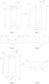
- Fig. 1 illustrates a front view of an electrode assembly 100 according to an embodiment of the present application.
- the electrode assembly 100 includes a first electrode sheet and a second electrode sheet spaced apart from each other, and a separator is disposed between the first electrode sheet and the second electrode sheet.
- the first electrode sheet and the second electrode sheet are wound or stacked to form the electrode assembly.
- the electrode assembly 100 includes a first end portion 114, a second end portion 115, a first main plane 116, a second main plane 117, and a binding layer.
- the second end portion 115 and the first end portion 114 are arranged oppositely, and the first main plane 116 and the second main plane 117 are arranged oppositely.
- the binding layer includes a first area 131 and a second area 132; the first area 131 is arranged at the first end portion 114 while the second area 132 is arranged at the first main plane 116; the first area 131 winds around the first end portion 114 to connect to the second area 132.
Landscapes
- Chemical & Material Sciences (AREA)
- Chemical Kinetics & Catalysis (AREA)
- Electrochemistry (AREA)
- General Chemical & Material Sciences (AREA)
- Engineering & Computer Science (AREA)
- Manufacturing & Machinery (AREA)
- Secondary Cells (AREA)
Description
- The present application relates to a field of electrochemical devices, more particularly to an electrode assembly and a battery having the same.
- At present, a conventional battery structure generally uses an adhesive layer to connect a cell with a package casing to prevent the cell from sliding relative to the package casing during the drop so as to prevent head and tail portions of the cell from colliding, which may otherwise result in deformation and hence a short circuit. A pull force generated during the drop acts on a single-sided anode area or on an uncoated aluminum foil of an outer layer of the cell, which will probably tear the aluminum foil. Additionally, in order to prevent the separator from folding during the drop, a few tapes are applied around the head and tail portions of the cell. But the tapes around the head and tail portions will also pull the aluminum foil, and hence have a high probability of tearing the aluminum foil. Many particles and burrs are produced after the aluminum foil is torn, and these particles and burrs probably pierce the separator, thereby leading to a short circuit between the aluminum foil and a copper foil or between a cathode and the copper foil, and eventually causing the cell to heat up and fail.
- American patent application
US2018/083311 discloses a rechargeable lithium battery including tape, an electrode assembly, and a case housing the electrode assembly. International patent applicationWO2018/066886 discloses an electrode assembly with an adhesive coating layer coated on the outer surface of the electrode assembly. Korean patent applicationKR 2018 0041527 - The present application aims to propose an electrode assembly and a battery including the electrode assembly, and the battery has an advantage of excellent safety performance. The invention is defined in claims 1 and 14. Preferred embodiments are defined in claims 2-13.
- For the battery according to the present application, by providing the first area and the second area and connecting the first area with the second area, the adhesion of the second area to the battery is transferred to the first area during the drop of the battery. Therefore, the tear of the electrode assembly due to the drop, which may cause failure of the battery, is avoided.
- These and/or additional aspects and advantages of embodiments of the present application will become apparent and more readily appreciated from the following descriptions made with reference to the drawings, in which:
-
Figs. 1-4 illustrate a front view, a rear view, a top view and a bottom view according to an embodiment of the present application respectively. -
Fig. 5 illustrates a front view according to another embodiment of the present application. -
Fig. 6 illustrates a bottom view according to the embodiment shown inFig. 5 . -
Fig. 7 illustrates a front view according to another embodiment of the present application. -
Fig. 8 illustrates a rear view according to the embodiment shown inFig. 7 . -
Fig. 9 illustrates a top view according to the embodiment shown inFig. 7 . -
Fig. 10 illustrates a top view according to another embodiment of the present application. -
Fig. 11 illustrates a top view according to another embodiment of the present application. -
Fig. 12 illustrates a front view according to another embodiment of the present application. -
Fig. 13 illustrates a front view according to another embodiment of the present application. -
Fig. 14 illustrates a front view according to another embodiment of the present application. -
Fig. 15 illustrates a separator structure according to an embodiment of the present application. - Embodiments of the present application will be described in detail and examples of the embodiments will be illustrated in the drawings, where same or similar reference numerals are used to indicate same or similar elements or elements with same or similar functions. The embodiments described herein with reference to drawings are explanatory, and only used to generally understand the present application. The embodiments shall not be construed to limit the present application.
- The electrode assemblies and batteries according to embodiments of the present application will be described with reference to
Figs. 1-15 . -
Fig. 1 illustrates a front view of anelectrode assembly 100 according to an embodiment of the present application. In this embodiment, theelectrode assembly 100 includes a first electrode sheet and a second electrode sheet spaced apart from each other, and a separator is disposed between the first electrode sheet and the second electrode sheet. The first electrode sheet and the second electrode sheet are wound or stacked to form the electrode assembly. Theelectrode assembly 100 includes afirst end portion 114, asecond end portion 115, a firstmain plane 116, a secondmain plane 117, and a binding layer. Thesecond end portion 115 and thefirst end portion 114 are arranged oppositely, and the firstmain plane 116 and the secondmain plane 117 are arranged oppositely. The binding layer includes afirst area 131 and asecond area 132; thefirst area 131 is arranged at thefirst end portion 114 while thesecond area 132 is arranged at the firstmain plane 116; thefirst area 131 winds around thefirst end portion 114 to connect to thesecond area 132. - By providing the
first area 131 and thesecond area 132 and connecting thefirst area 131 with thesecond area 132, adhesion of thesecond area 132 to the battery is transferred to thefirst area 131 during the drop of the battery, to avoid tearing theelectrode assembly 100 due to the drop, which may otherwise cause failure of the battery. - According to another embodiment of the present application, a part of the
first area 131 may also be arranged at the separator or the first electrode sheet. Therefore an external force received during the use of the electrode assembly can be partially transferred to an interior of theelectrode assembly 100 through thefirst area 131 which is connected to thesecond area 132. Optionally, thefirst area 131 may extend from the separator or the first electrode sheet, such that an external force received by thefirst area 131 can also be partially transferred to the interior of theelectrode assembly 100. - According to an embodiment of the present application, a first adhesive layer can be provided to a first surface of the
first area 131 close to theelectrode assembly 100, such that thefirst area 131 adheres to theelectrode assembly 100. By providing a first surface of thesecond area 132 close to theelectrode assembly 100 with a second adhesive layer, thesecond area 132 can adhere to theelectrode assembly 100. Thefirst area 131 and thesecond area 132 can be connected by means of the first adhesive layer or the second adhesive layer, as well. Certainly, according to another embodiment of the present application, thesecond area 132 may be an extension of thefirst area 131 on the firstmain plane 116 of theelectrode assembly 100. -
Figs. 2-4 illustrate a rear view, a top view and a bottom view of the embodiment shown inFig. 1 , respectively. Referring toFig. 3 , a part of thefirst area 131 can be arranged at the separator or the first electrode sheet, or extend from the separator or the first electrode sheet, and be partially connected to thesecond area 132. Referring toFigs. 1-4 , thefirst area 131 and thesecond area 132 can be partially overlapped and be connected. - Referring to
Figs. 1-4 , in theelectrode assembly 100 according to an embodiment of the present application, the binding layer can further include athird area 133 arranged at thesecond end portion 115. Thethird area 133 has a first end arranged at the firstmain plane 116 and a second end arranged at the secondmain plane 117, that is, thethird area 133 can be winded around thesecond end portion 115 to connect to thesecond area 132. Certainly, according to an embodiment of the present application, thethird area 133 can be formed by extension of the separator or the first electrode sheet, and partially overlapped and connected to thesecond area 132. - In addition, the electrode assembly according to an embodiment of the present application can further include a
tab 120 provided to thefirst end portion 114. Thetab 120 can include afirst tab 121 and asecond tab 122, and thefirst tab 121 and thesecond tab 122 are both located at one side of thefirst end portion 114. - Referring to
Fig. 1 , in an a-a' direction, thefirst area 131 may have a width smaller than a width of thesecond area 132, and thethird area 133 may have a width smaller than the width of thesecond area 132. For example, the width of thethird area 133 may be 11 mm. - According to another embodiment of the present application, in the a-a' direction, the width of the
first area 131 may be greater than the width of thesecond area 132, and the width of thethird area 133 may be greater than the width of thesecond area 132. -
Fig. 5 illustrates theelectrode assembly 100 according to an embodiment of the present application. Different from the embodiment shown inFig. 1 , the binding layer includes twothird areas 133 in this embodiment. The twothird areas 133 are arranged in the a-a' direction shown inFig. 5 . Each of thethird regions 133 is winded around thesecond end portion 115, and eachthird region 133 has a first end overlapping with and connecting to thesecond area 132. Moreover, in the a-a' direction, each of thethird regions 133 may have a width smaller than the width of thesecond area 132.Fig. 6 shows a bottom view of theelectrode assembly 100 according to the embodiment shown inFig. 5 , and illustrates twothird areas 133. -
Figs. 7-9 illustrate theelectrode assembly 100 according to another embodiment of the present application. Different from the embodiment shown inFig. 1 , the binding layer further includes afourth area 134; thefourth area 134 is arranged at the secondmain plane 117, and overlaps with and adheres to a part of thefirst area 131 and a part of thethird area 133, respectively. - According to an embodiment of the present application, a third adhesive layer can be provided to a first surface of the
fourth area 134 close to theelectrode assembly 100, such that thefourth area 134 adheres to theelectrode assembly 100. A fourth adhesive layer can be provided to a second surface of thefourth area 134 away from theelectrode assembly 100, and the fourth adhesive layer can be used to make theelectrode assembly 100 adhere to a casing that accommodates theelectrode assembly 100. Certainly, according to another embodiment of the present application, thefourth area 134 may be an extension of thefirst area 131 on the secondmain plane 117 of theelectrode assembly 100; thefourth area 134 may be an extension of thethird area 133 on the secondmain plane 117 of theelectrode assembly 100. - Referring to
Figs. 7-8 , in the a-a' direction, the width of thethird area 133 may be smaller than a width of thefourth area 134, and the width of thefirst area 131 may be greater than the width of thefourth area 134. According to another embodiment of the present application, the width of thethird area 133 may be greater than the width of thefourth area 134, and the width of thefirst area 131 may be smaller than the width of thefourth area 134. - Referring to
Fig. 9 , in order to facilitate the arrangement of thetab 120, thefirst area 131 is provided with a throughhole 1311. That is, when the width of thefirst area 131 is greater than a spacing between the tabs, thetab 120 can pass through the throughhole 1311. Thetab 120 partially or completely passes through the throughhole 1311, that is, the throughhole 1311 may be an open or closed hole.Fig. 10 illustrates a case where thetab 120 completely passes through the throughhole 1311. Thus, the structure described above is applicable to a battery with a narrow spacing between the twotabs 120. Moreover, the operation is simple. Further, a tape is eliminated. And the energy density loss is little. -
Fig. 11 illustrates another embodiment of the present application. According toFig. 11 , when the spacing between the tabs is relatively wide, thefirst area 131 can be arranged between thefirst tab 121 and thesecond tab 122, that is, orthographic projections of thefirst tab 121, thesecond tab 122 and thesecond area 132 on the firstmain plane 116 do not overlap. -
Fig. 12 illustrates another embodiment of the present application. According toFig. 12 , when the spacing between the tabs is relatively narrow, thefirst tab 121 and thesecond tab 122 can be arranged at the same side of thefirst area 131. -
Fig. 13 illustrates theelectrode assembly 100 according to another embodiment of the present application. In this embodiment, thesecond area 132 exhibits an irregular pattern (or abnormally shaped), which can be made by cutting a rectangular sheet. For example, thesecond area 132 is constructed by cutting a right angle of the rectangular sheet, and the orthographic projections of thefirst tab 121, thesecond tab 122 and thesecond area 132 on the firstmain plane 116 do not overlap, thereby reducing an overall thickness of the battery. -
Fig. 14 illustrates theelectrode assembly 100 according to another embodiment of the present application. In this embodiment, thefirst area 131 can include a firstbinding unit 130a and a secondbinding unit 130b, and the firstbinding unit 130a and the secondbinding unit 130b connect to thesecond area 132, respectively. The firstbinding unit 130a and the secondbinding unit 130b can be arranged at two sides of thetab 120; or at least one of the firstbinding unit 130a and the secondbinding unit 130b can be arranged between thefirst tab 121 and thesecond tab 122. - Reference throughout this specification to "an embodiment," "some embodiments," "an exemplary embodiment," "an example," "a specific example," or "some examples," means that a particular feature, structure, material, or characteristic described in connection with the embodiment or example is included in at least one embodiment or example of the present application. Thus, the appearances of the above phrases throughout this specification do not necessarily refer to the same embodiment or example. Furthermore, the particular features, structures, materials, or characteristics may be combined in any suitable manner in one or more embodiments or examples.
- Although embodiments of the present application have been shown and described, it would be appreciated by those skilled in the art that various changes can be made to the embodiments of the present invention as long as they are within the scope of the current claims.
Claims (14)
- An electrode assembly (100), comprising a first electrode sheet, a second electrode sheet, and a separator disposed therebetween, wherein the first electrode sheet and the second electrode sheet are wound or stacked to form the electrode assembly (100),
wherein the electrode assembly (100) comprises:a first end portion (114) provided with a tab (120),a second end portion (115) arranged opposite to the first end portion (114),a first main plane (116),a second main plane (117) arranged opposite to the first main plane (116), anda binding layer comprising:a first area (131) arranged at the first end portion (114), anda second area (132) arranged at the first main plane (116),wherein the first area (131) is connected to the second area (132) andwherein the first area (131) is provided with a through hole (1311), and the tab (120) passes through the through hole (1311). - The electrode assembly (100) according to claim 1, wherein a part of the first area (131) is arranged at the separator or the first electrode sheet.
- The electrode assembly (100) according to claim 2, wherein the first area (131) extends from the first electrode sheet or the separator.
- The electrode assembly (100) according to any one of claims 1 to 3, wherein the first area (131) and the second area (132) partially overlap.
- The electrode assembly (100) according to any one of claims 1 to 4, wherein the first area (131) comprises a first binding unit (130a) and a second binding unit (130b), and the first binding unit (130a) and the second binding unit (130b) are respectively connected to the second area (132).
- The electrode assembly (100) according to any one of claims 1 to 5, wherein a first surface of the first area (131) close to the electrode assembly (100) is provided with a first adhesive layer.
- The electrode assembly (100) according to any one of claims 1 to 6, wherein a first surface of the second area (132) close to the electrode assembly (100) is provided with a second adhesive layer.
- The electrode assembly (100) according to any one of claims 1 to 7, wherein the binding layer further comprises a third area (133) arranged at the second end portion (115) and connected to the second area (132).
- The electrode assembly (100) according to claim 8, wherein the third area (133) has a first end arranged at the first main plane (116) and a second end arranged at the second main plane (117).
- The electrode assembly (100) according to claim 8 or 9, wherein the binding layer further comprises a fourth area arranged at the second main plane (117) and connected to the first area (131).
- The electrode assembly (100) according to claim 10, wherein the fourth area (134) is connected to the third area (133).
- The electrode assembly (100) according to claim 11, wherein a first surface of the fourth area (134) is provided with a third adhesive layer; and a second surface of the fourth area (134) is provided with a fourth adhesive layer;
wherein the first surface of the fourth area (134) faces the electrode assembly (100), and the second surface of the fourth area (134) faces away from the electrode assembly (100). - The electrode assembly (100) according to claim 12, wherein the third adhesive layer has an adhesion force different from an adhesion force of the fourth adhesive layer.
- A battery, comprising:
an electrode assembly (100) according to any one of claims 1 to 13, and a casing accommodating the electrode assembly (100).
Applications Claiming Priority (1)
| Application Number | Priority Date | Filing Date | Title |
|---|---|---|---|
| CN201811376277.9A CN111200155A (en) | 2018-11-19 | 2018-11-19 | Electrode assembly and battery including the same |
Publications (2)
| Publication Number | Publication Date |
|---|---|
| EP3654433A1 EP3654433A1 (en) | 2020-05-20 |
| EP3654433B1 true EP3654433B1 (en) | 2025-07-02 |
Family
ID=68609998
Family Applications (1)
| Application Number | Title | Priority Date | Filing Date |
|---|---|---|---|
| EP19209746.7A Active EP3654433B1 (en) | 2018-11-19 | 2019-11-18 | Electrode assembly and battery having the same |
Country Status (3)
| Country | Link |
|---|---|
| US (1) | US20200161694A1 (en) |
| EP (1) | EP3654433B1 (en) |
| CN (1) | CN111200155A (en) |
Families Citing this family (3)
| Publication number | Priority date | Publication date | Assignee | Title |
|---|---|---|---|---|
| CN113795968B (en) * | 2020-12-31 | 2024-02-23 | 宁德新能源科技有限公司 | Batteries and electronic devices using said batteries |
| CN115133184B (en) * | 2021-03-29 | 2023-10-03 | 宁德新能源科技有限公司 | Cells, batteries and electrical equipment |
| CN114175302B (en) * | 2021-03-30 | 2024-03-26 | 宁德新能源科技有限公司 | Cells and batteries |
Family Cites Families (16)
| Publication number | Priority date | Publication date | Assignee | Title |
|---|---|---|---|---|
| JP2001307764A (en) * | 2000-04-20 | 2001-11-02 | Toshiba Battery Co Ltd | Alkaline secondary battery and its production |
| WO2008130148A1 (en) * | 2007-04-20 | 2008-10-30 | Lg Chem, Ltd. | Battery cell of improved safety |
| US7871720B2 (en) * | 2008-04-30 | 2011-01-18 | Apple Inc. | Battery assembly for use in an electronic device |
| KR101136254B1 (en) * | 2010-05-20 | 2012-04-19 | 삼성에스디아이 주식회사 | Secondary battery |
| US20140212701A1 (en) * | 2013-01-29 | 2014-07-31 | Samsung Sdi Co., Ltd. | Battery cell |
| KR101595611B1 (en) * | 2013-03-22 | 2016-02-18 | 주식회사 엘지화학 | a secondary battery for improving energy degree |
| KR102154327B1 (en) * | 2013-12-16 | 2020-09-09 | 삼성에스디아이 주식회사 | Jelly roll tape for rechargeable battery and rechargeable battery having the same |
| CN203690420U (en) * | 2014-01-23 | 2014-07-02 | 东莞新能源科技有限公司 | Lithium ion battery |
| CN105449255B (en) * | 2014-08-05 | 2019-01-08 | 东莞新能源科技有限公司 | Electrochemical energy storage device |
| WO2017047787A1 (en) * | 2015-09-18 | 2017-03-23 | リチウム エナジー アンド パワー ゲゼルシャフト ミット ベシュレンクテル ハフッング ウント コンパニー コマンディトゲゼルシャフト | Power storage element and method for manufacturing power storage element |
| KR102028737B1 (en) * | 2015-10-15 | 2019-10-04 | 주식회사 엘지화학 | Pouch-typed Battery Cell Having Electrode Lead of Folded Structure |
| CN106992320A (en) * | 2016-01-20 | 2017-07-28 | 松下能源(无锡)有限公司 | Battery with nonaqueous electrolyte |
| CN107799781A (en) * | 2016-09-05 | 2018-03-13 | 深圳市和合自动化有限公司 | A kind of battery core sticking method |
| KR102278442B1 (en) * | 2016-09-21 | 2021-07-16 | 삼성에스디아이 주식회사 | Rechargeable lithium battery |
| KR20180037748A (en) * | 2016-10-05 | 2018-04-13 | 삼성에스디아이 주식회사 | Secondary Battery |
| KR102256478B1 (en) * | 2016-10-14 | 2021-05-27 | 주식회사 엘지에너지솔루션 | Electrode assembly |
-
2018
- 2018-11-19 CN CN201811376277.9A patent/CN111200155A/en active Pending
-
2019
- 2019-10-01 US US16/590,211 patent/US20200161694A1/en not_active Abandoned
- 2019-11-18 EP EP19209746.7A patent/EP3654433B1/en active Active
Also Published As
| Publication number | Publication date |
|---|---|
| EP3654433A1 (en) | 2020-05-20 |
| US20200161694A1 (en) | 2020-05-21 |
| CN111200155A (en) | 2020-05-26 |
Similar Documents
| Publication | Publication Date | Title |
|---|---|---|
| US11108089B2 (en) | Cell, battery and electronic device | |
| US11824166B2 (en) | Secondary battery | |
| KR100515833B1 (en) | Jelly-roll type electrode assembly and secondary battery applying the same | |
| US20170187025A1 (en) | Secondary battery | |
| US10693192B2 (en) | Wound-type cell | |
| WO2021232314A1 (en) | Electrode assembly and battery | |
| US11245135B2 (en) | Secondary battery with insulating tapes | |
| JPWO2017010046A1 (en) | Winding battery | |
| CN114586217A (en) | Electrochemical device and electronic device including the same | |
| US20190013550A1 (en) | Wound-type cell | |
| EP3654433A1 (en) | Electrode assembly and battery having the same | |
| KR20160016049A (en) | Secondary battery | |
| JP2018055904A (en) | Electrochemical cell and manufacturing method of the electrochemical cell | |
| WO2022204943A1 (en) | Battery cell and battery | |
| CN220527152U (en) | a battery | |
| CN113054212A (en) | Winding type battery cell and battery | |
| CN115133184A (en) | Battery cell, battery and electric equipment | |
| CN119153753B (en) | Manufacturing methods for secondary batteries, electrical equipment, and electrode sheets | |
| CN115117458A (en) | Battery core and battery | |
| US20250149725A1 (en) | Rechargeable battery | |
| US20250015468A1 (en) | Secondary battery | |
| EP4742330A1 (en) | Electrode current collector, electrode assembly comprising electrode current collector, and method for manufacturing electrode current collector | |
| EP4700875A1 (en) | Battery | |
| US20250112341A1 (en) | Secondary battery | |
| EP4734269A1 (en) | Electrode current collector, electrode assembly comprising electrode current collector, and method for manufacturing electrode current collector |
Legal Events
| Date | Code | Title | Description |
|---|---|---|---|
| PUAI | Public reference made under article 153(3) epc to a published international application that has entered the european phase |
Free format text: ORIGINAL CODE: 0009012 |
|
| STAA | Information on the status of an ep patent application or granted ep patent |
Free format text: STATUS: THE APPLICATION HAS BEEN PUBLISHED |
|
| AK | Designated contracting states |
Kind code of ref document: A1 Designated state(s): AL AT BE BG CH CY CZ DE DK EE ES FI FR GB GR HR HU IE IS IT LI LT LU LV MC MK MT NL NO PL PT RO RS SE SI SK SM TR |
|
| AX | Request for extension of the european patent |
Extension state: BA ME |
|
| STAA | Information on the status of an ep patent application or granted ep patent |
Free format text: STATUS: REQUEST FOR EXAMINATION WAS MADE |
|
| 17P | Request for examination filed |
Effective date: 20201119 |
|
| RBV | Designated contracting states (corrected) |
Designated state(s): AL AT BE BG CH CY CZ DE DK EE ES FI FR GB GR HR HU IE IS IT LI LT LU LV MC MK MT NL NO PL PT RO RS SE SI SK SM TR |
|
| STAA | Information on the status of an ep patent application or granted ep patent |
Free format text: STATUS: EXAMINATION IS IN PROGRESS |
|
| 17Q | First examination report despatched |
Effective date: 20240909 |
|
| GRAP | Despatch of communication of intention to grant a patent |
Free format text: ORIGINAL CODE: EPIDOSNIGR1 |
|
| STAA | Information on the status of an ep patent application or granted ep patent |
Free format text: STATUS: GRANT OF PATENT IS INTENDED |
|
| RIC1 | Information provided on ipc code assigned before grant |
Ipc: H01M 50/54 20210101ALI20250310BHEP Ipc: H01M 50/531 20210101ALI20250310BHEP Ipc: H01M 10/0587 20100101ALI20250310BHEP Ipc: H01M 10/04 20060101AFI20250310BHEP |
|
| INTG | Intention to grant announced |
Effective date: 20250325 |
|
| GRAS | Grant fee paid |
Free format text: ORIGINAL CODE: EPIDOSNIGR3 |
|
| GRAA | (expected) grant |
Free format text: ORIGINAL CODE: 0009210 |
|
| STAA | Information on the status of an ep patent application or granted ep patent |
Free format text: STATUS: THE PATENT HAS BEEN GRANTED |
|
| P01 | Opt-out of the competence of the unified patent court (upc) registered |
Free format text: CASE NUMBER: APP_24113/2025 Effective date: 20250520 |
|
| RAP3 | Party data changed (applicant data changed or rights of an application transferred) |
Owner name: NINGDE AMPEREX TECHNOLOGY LIMITED |
|
| AK | Designated contracting states |
Kind code of ref document: B1 Designated state(s): AL AT BE BG CH CY CZ DE DK EE ES FI FR GB GR HR HU IE IS IT LI LT LU LV MC MK MT NL NO PL PT RO RS SE SI SK SM TR |
|
| REG | Reference to a national code |
Ref country code: GB Ref legal event code: FG4D |
|
| REG | Reference to a national code |
Ref country code: CH Ref legal event code: EP |
|
| REG | Reference to a national code |
Ref country code: DE Ref legal event code: R096 Ref document number: 602019071879 Country of ref document: DE |
|
| REG | Reference to a national code |
Ref country code: IE Ref legal event code: FG4D |
|
| REG | Reference to a national code |
Ref country code: NL Ref legal event code: FP |
|
| PGFP | Annual fee paid to national office [announced via postgrant information from national office to epo] |
Ref country code: NL Payment date: 20251015 Year of fee payment: 7 |
|
| PG25 | Lapsed in a contracting state [announced via postgrant information from national office to epo] |
Ref country code: PT Free format text: LAPSE BECAUSE OF FAILURE TO SUBMIT A TRANSLATION OF THE DESCRIPTION OR TO PAY THE FEE WITHIN THE PRESCRIBED TIME-LIMIT Effective date: 20251103 |
|
| REG | Reference to a national code |
Ref country code: AT Ref legal event code: MK05 Ref document number: 1810308 Country of ref document: AT Kind code of ref document: T Effective date: 20250702 |
|
| PG25 | Lapsed in a contracting state [announced via postgrant information from national office to epo] |
Ref country code: IS Free format text: LAPSE BECAUSE OF FAILURE TO SUBMIT A TRANSLATION OF THE DESCRIPTION OR TO PAY THE FEE WITHIN THE PRESCRIBED TIME-LIMIT Effective date: 20251102 |
|
| PGFP | Annual fee paid to national office [announced via postgrant information from national office to epo] |
Ref country code: DE Payment date: 20251007 Year of fee payment: 7 |
|
| PGFP | Annual fee paid to national office [announced via postgrant information from national office to epo] |
Ref country code: GB Payment date: 20251016 Year of fee payment: 7 |
|
| PG25 | Lapsed in a contracting state [announced via postgrant information from national office to epo] |
Ref country code: NO Free format text: LAPSE BECAUSE OF FAILURE TO SUBMIT A TRANSLATION OF THE DESCRIPTION OR TO PAY THE FEE WITHIN THE PRESCRIBED TIME-LIMIT Effective date: 20251002 |
|
| REG | Reference to a national code |
Ref country code: LT Ref legal event code: MG9D |
|
| PG25 | Lapsed in a contracting state [announced via postgrant information from national office to epo] |
Ref country code: AT Free format text: LAPSE BECAUSE OF FAILURE TO SUBMIT A TRANSLATION OF THE DESCRIPTION OR TO PAY THE FEE WITHIN THE PRESCRIBED TIME-LIMIT Effective date: 20250702 |
|
| PG25 | Lapsed in a contracting state [announced via postgrant information from national office to epo] |
Ref country code: FI Free format text: LAPSE BECAUSE OF FAILURE TO SUBMIT A TRANSLATION OF THE DESCRIPTION OR TO PAY THE FEE WITHIN THE PRESCRIBED TIME-LIMIT Effective date: 20250702 |
|
| PG25 | Lapsed in a contracting state [announced via postgrant information from national office to epo] |
Ref country code: HR Free format text: LAPSE BECAUSE OF FAILURE TO SUBMIT A TRANSLATION OF THE DESCRIPTION OR TO PAY THE FEE WITHIN THE PRESCRIBED TIME-LIMIT Effective date: 20250702 |
|
| PGFP | Annual fee paid to national office [announced via postgrant information from national office to epo] |
Ref country code: FR Payment date: 20251008 Year of fee payment: 7 |
|
| PG25 | Lapsed in a contracting state [announced via postgrant information from national office to epo] |
Ref country code: GR Free format text: LAPSE BECAUSE OF FAILURE TO SUBMIT A TRANSLATION OF THE DESCRIPTION OR TO PAY THE FEE WITHIN THE PRESCRIBED TIME-LIMIT Effective date: 20251003 |
|
| PG25 | Lapsed in a contracting state [announced via postgrant information from national office to epo] |
Ref country code: SE Free format text: LAPSE BECAUSE OF FAILURE TO SUBMIT A TRANSLATION OF THE DESCRIPTION OR TO PAY THE FEE WITHIN THE PRESCRIBED TIME-LIMIT Effective date: 20250702 Ref country code: CZ Free format text: LAPSE BECAUSE OF FAILURE TO SUBMIT A TRANSLATION OF THE DESCRIPTION OR TO PAY THE FEE WITHIN THE PRESCRIBED TIME-LIMIT Effective date: 20250702 |
|
| PG25 | Lapsed in a contracting state [announced via postgrant information from national office to epo] |
Ref country code: LV Free format text: LAPSE BECAUSE OF FAILURE TO SUBMIT A TRANSLATION OF THE DESCRIPTION OR TO PAY THE FEE WITHIN THE PRESCRIBED TIME-LIMIT Effective date: 20250702 |
|
| PG25 | Lapsed in a contracting state [announced via postgrant information from national office to epo] |
Ref country code: PL Free format text: LAPSE BECAUSE OF FAILURE TO SUBMIT A TRANSLATION OF THE DESCRIPTION OR TO PAY THE FEE WITHIN THE PRESCRIBED TIME-LIMIT Effective date: 20250702 Ref country code: BG Free format text: LAPSE BECAUSE OF FAILURE TO SUBMIT A TRANSLATION OF THE DESCRIPTION OR TO PAY THE FEE WITHIN THE PRESCRIBED TIME-LIMIT Effective date: 20250702 |
|
| PG25 | Lapsed in a contracting state [announced via postgrant information from national office to epo] |
Ref country code: RS Free format text: LAPSE BECAUSE OF FAILURE TO SUBMIT A TRANSLATION OF THE DESCRIPTION OR TO PAY THE FEE WITHIN THE PRESCRIBED TIME-LIMIT Effective date: 20251002 |
|
| PG25 | Lapsed in a contracting state [announced via postgrant information from national office to epo] |
Ref country code: ES Free format text: LAPSE BECAUSE OF FAILURE TO SUBMIT A TRANSLATION OF THE DESCRIPTION OR TO PAY THE FEE WITHIN THE PRESCRIBED TIME-LIMIT Effective date: 20250702 |
|
| PG25 | Lapsed in a contracting state [announced via postgrant information from national office to epo] |
Ref country code: RO Free format text: LAPSE BECAUSE OF FAILURE TO SUBMIT A TRANSLATION OF THE DESCRIPTION OR TO PAY THE FEE WITHIN THE PRESCRIBED TIME-LIMIT Effective date: 20250702 |
|
| PG25 | Lapsed in a contracting state [announced via postgrant information from national office to epo] |
Ref country code: SM Free format text: LAPSE BECAUSE OF FAILURE TO SUBMIT A TRANSLATION OF THE DESCRIPTION OR TO PAY THE FEE WITHIN THE PRESCRIBED TIME-LIMIT Effective date: 20250702 |
|
| PG25 | Lapsed in a contracting state [announced via postgrant information from national office to epo] |
Ref country code: DK Free format text: LAPSE BECAUSE OF FAILURE TO SUBMIT A TRANSLATION OF THE DESCRIPTION OR TO PAY THE FEE WITHIN THE PRESCRIBED TIME-LIMIT Effective date: 20250702 |
|
| PG25 | Lapsed in a contracting state [announced via postgrant information from national office to epo] |
Ref country code: IT Free format text: LAPSE BECAUSE OF FAILURE TO SUBMIT A TRANSLATION OF THE DESCRIPTION OR TO PAY THE FEE WITHIN THE PRESCRIBED TIME-LIMIT Effective date: 20250702 |
|
| PG25 | Lapsed in a contracting state [announced via postgrant information from national office to epo] |
Ref country code: SK Free format text: LAPSE BECAUSE OF FAILURE TO SUBMIT A TRANSLATION OF THE DESCRIPTION OR TO PAY THE FEE WITHIN THE PRESCRIBED TIME-LIMIT Effective date: 20250702 Ref country code: EE Free format text: LAPSE BECAUSE OF FAILURE TO SUBMIT A TRANSLATION OF THE DESCRIPTION OR TO PAY THE FEE WITHIN THE PRESCRIBED TIME-LIMIT Effective date: 20250702 |
|
| PLBE | No opposition filed within time limit |
Free format text: ORIGINAL CODE: 0009261 |
|
| STAA | Information on the status of an ep patent application or granted ep patent |
Free format text: STATUS: NO OPPOSITION FILED WITHIN TIME LIMIT |