EP3654409A1 - Electrode assembly and method of manufacturing the same - Google Patents
Electrode assembly and method of manufacturing the same Download PDFInfo
- Publication number
- EP3654409A1 EP3654409A1 EP19210077.4A EP19210077A EP3654409A1 EP 3654409 A1 EP3654409 A1 EP 3654409A1 EP 19210077 A EP19210077 A EP 19210077A EP 3654409 A1 EP3654409 A1 EP 3654409A1
- Authority
- EP
- European Patent Office
- Prior art keywords
- electrode
- adhesive layer
- electrode assembly
- separator
- fixing member
- Prior art date
- Legal status (The legal status is an assumption and is not a legal conclusion. Google has not performed a legal analysis and makes no representation as to the accuracy of the status listed.)
- Granted
Links
Images







Classifications
-
- H—ELECTRICITY
- H01—ELECTRIC ELEMENTS
- H01M—PROCESSES OR MEANS, e.g. BATTERIES, FOR THE DIRECT CONVERSION OF CHEMICAL ENERGY INTO ELECTRICAL ENERGY
- H01M4/00—Electrodes
- H01M4/02—Electrodes composed of, or comprising, active material
- H01M4/04—Processes of manufacture in general
-
- H—ELECTRICITY
- H01—ELECTRIC ELEMENTS
- H01M—PROCESSES OR MEANS, e.g. BATTERIES, FOR THE DIRECT CONVERSION OF CHEMICAL ENERGY INTO ELECTRICAL ENERGY
- H01M10/00—Secondary cells; Manufacture thereof
- H01M10/04—Construction or manufacture in general
- H01M10/0404—Machines for assembling batteries
-
- H—ELECTRICITY
- H01—ELECTRIC ELEMENTS
- H01M—PROCESSES OR MEANS, e.g. BATTERIES, FOR THE DIRECT CONVERSION OF CHEMICAL ENERGY INTO ELECTRICAL ENERGY
- H01M10/00—Secondary cells; Manufacture thereof
- H01M10/04—Construction or manufacture in general
- H01M10/0413—Large-sized flat cells or batteries for motive or stationary systems with plate-like electrodes
-
- H—ELECTRICITY
- H01—ELECTRIC ELEMENTS
- H01M—PROCESSES OR MEANS, e.g. BATTERIES, FOR THE DIRECT CONVERSION OF CHEMICAL ENERGY INTO ELECTRICAL ENERGY
- H01M10/00—Secondary cells; Manufacture thereof
- H01M10/04—Construction or manufacture in general
- H01M10/0436—Small-sized flat cells or batteries for portable equipment
-
- H—ELECTRICITY
- H01—ELECTRIC ELEMENTS
- H01M—PROCESSES OR MEANS, e.g. BATTERIES, FOR THE DIRECT CONVERSION OF CHEMICAL ENERGY INTO ELECTRICAL ENERGY
- H01M10/00—Secondary cells; Manufacture thereof
- H01M10/04—Construction or manufacture in general
- H01M10/0463—Cells or batteries with horizontal or inclined electrodes
-
- H—ELECTRICITY
- H01—ELECTRIC ELEMENTS
- H01M—PROCESSES OR MEANS, e.g. BATTERIES, FOR THE DIRECT CONVERSION OF CHEMICAL ENERGY INTO ELECTRICAL ENERGY
- H01M10/00—Secondary cells; Manufacture thereof
- H01M10/05—Accumulators with non-aqueous electrolyte
- H01M10/052—Li-accumulators
-
- H—ELECTRICITY
- H01—ELECTRIC ELEMENTS
- H01M—PROCESSES OR MEANS, e.g. BATTERIES, FOR THE DIRECT CONVERSION OF CHEMICAL ENERGY INTO ELECTRICAL ENERGY
- H01M10/00—Secondary cells; Manufacture thereof
- H01M10/05—Accumulators with non-aqueous electrolyte
- H01M10/058—Construction or manufacture
- H01M10/0585—Construction or manufacture of accumulators having only flat construction elements, i.e. flat positive electrodes, flat negative electrodes and flat separators
-
- H—ELECTRICITY
- H01—ELECTRIC ELEMENTS
- H01M—PROCESSES OR MEANS, e.g. BATTERIES, FOR THE DIRECT CONVERSION OF CHEMICAL ENERGY INTO ELECTRICAL ENERGY
- H01M50/00—Constructional details or processes of manufacture of the non-active parts of electrochemical cells other than fuel cells, e.g. hybrid cells
- H01M50/40—Separators; Membranes; Diaphragms; Spacing elements inside cells
- H01M50/403—Manufacturing processes of separators, membranes or diaphragms
-
- H—ELECTRICITY
- H01—ELECTRIC ELEMENTS
- H01M—PROCESSES OR MEANS, e.g. BATTERIES, FOR THE DIRECT CONVERSION OF CHEMICAL ENERGY INTO ELECTRICAL ENERGY
- H01M50/00—Constructional details or processes of manufacture of the non-active parts of electrochemical cells other than fuel cells, e.g. hybrid cells
- H01M50/40—Separators; Membranes; Diaphragms; Spacing elements inside cells
- H01M50/409—Separators, membranes or diaphragms characterised by the material
- H01M50/411—Organic material
-
- H—ELECTRICITY
- H01—ELECTRIC ELEMENTS
- H01M—PROCESSES OR MEANS, e.g. BATTERIES, FOR THE DIRECT CONVERSION OF CHEMICAL ENERGY INTO ELECTRICAL ENERGY
- H01M50/00—Constructional details or processes of manufacture of the non-active parts of electrochemical cells other than fuel cells, e.g. hybrid cells
- H01M50/40—Separators; Membranes; Diaphragms; Spacing elements inside cells
- H01M50/409—Separators, membranes or diaphragms characterised by the material
- H01M50/411—Organic material
- H01M50/414—Synthetic resins, e.g. thermoplastics or thermosetting resins
- H01M50/417—Polyolefins
-
- H—ELECTRICITY
- H01—ELECTRIC ELEMENTS
- H01M—PROCESSES OR MEANS, e.g. BATTERIES, FOR THE DIRECT CONVERSION OF CHEMICAL ENERGY INTO ELECTRICAL ENERGY
- H01M50/00—Constructional details or processes of manufacture of the non-active parts of electrochemical cells other than fuel cells, e.g. hybrid cells
- H01M50/40—Separators; Membranes; Diaphragms; Spacing elements inside cells
- H01M50/46—Separators, membranes or diaphragms characterised by their combination with electrodes
-
- H—ELECTRICITY
- H01—ELECTRIC ELEMENTS
- H01M—PROCESSES OR MEANS, e.g. BATTERIES, FOR THE DIRECT CONVERSION OF CHEMICAL ENERGY INTO ELECTRICAL ENERGY
- H01M50/00—Constructional details or processes of manufacture of the non-active parts of electrochemical cells other than fuel cells, e.g. hybrid cells
- H01M50/40—Separators; Membranes; Diaphragms; Spacing elements inside cells
- H01M50/46—Separators, membranes or diaphragms characterised by their combination with electrodes
- H01M50/461—Separators, membranes or diaphragms characterised by their combination with electrodes with adhesive layers between electrodes and separators
-
- C—CHEMISTRY; METALLURGY
- C09—DYES; PAINTS; POLISHES; NATURAL RESINS; ADHESIVES; COMPOSITIONS NOT OTHERWISE PROVIDED FOR; APPLICATIONS OF MATERIALS NOT OTHERWISE PROVIDED FOR
- C09J—ADHESIVES; NON-MECHANICAL ASPECTS OF ADHESIVE PROCESSES IN GENERAL; ADHESIVE PROCESSES NOT PROVIDED FOR ELSEWHERE; USE OF MATERIALS AS ADHESIVES
- C09J2203/00—Applications of adhesives in processes or use of adhesives in the form of films or foils
- C09J2203/33—Applications of adhesives in processes or use of adhesives in the form of films or foils for batteries or fuel cells
-
- C—CHEMISTRY; METALLURGY
- C09—DYES; PAINTS; POLISHES; NATURAL RESINS; ADHESIVES; COMPOSITIONS NOT OTHERWISE PROVIDED FOR; APPLICATIONS OF MATERIALS NOT OTHERWISE PROVIDED FOR
- C09J—ADHESIVES; NON-MECHANICAL ASPECTS OF ADHESIVE PROCESSES IN GENERAL; ADHESIVE PROCESSES NOT PROVIDED FOR ELSEWHERE; USE OF MATERIALS AS ADHESIVES
- C09J2301/00—Additional features of adhesives in the form of films or foils
- C09J2301/30—Additional features of adhesives in the form of films or foils characterized by the chemical, physicochemical or physical properties of the adhesive or the carrier
- C09J2301/304—Additional features of adhesives in the form of films or foils characterized by the chemical, physicochemical or physical properties of the adhesive or the carrier the adhesive being heat-activatable, i.e. not tacky at temperatures inferior to 30°C
-
- Y—GENERAL TAGGING OF NEW TECHNOLOGICAL DEVELOPMENTS; GENERAL TAGGING OF CROSS-SECTIONAL TECHNOLOGIES SPANNING OVER SEVERAL SECTIONS OF THE IPC; TECHNICAL SUBJECTS COVERED BY FORMER USPC CROSS-REFERENCE ART COLLECTIONS [XRACs] AND DIGESTS
- Y02—TECHNOLOGIES OR APPLICATIONS FOR MITIGATION OR ADAPTATION AGAINST CLIMATE CHANGE
- Y02E—REDUCTION OF GREENHOUSE GAS [GHG] EMISSIONS, RELATED TO ENERGY GENERATION, TRANSMISSION OR DISTRIBUTION
- Y02E60/00—Enabling technologies; Technologies with a potential or indirect contribution to GHG emissions mitigation
- Y02E60/10—Energy storage using batteries
-
- Y—GENERAL TAGGING OF NEW TECHNOLOGICAL DEVELOPMENTS; GENERAL TAGGING OF CROSS-SECTIONAL TECHNOLOGIES SPANNING OVER SEVERAL SECTIONS OF THE IPC; TECHNICAL SUBJECTS COVERED BY FORMER USPC CROSS-REFERENCE ART COLLECTIONS [XRACs] AND DIGESTS
- Y02—TECHNOLOGIES OR APPLICATIONS FOR MITIGATION OR ADAPTATION AGAINST CLIMATE CHANGE
- Y02P—CLIMATE CHANGE MITIGATION TECHNOLOGIES IN THE PRODUCTION OR PROCESSING OF GOODS
- Y02P70/00—Climate change mitigation technologies in the production process for final industrial or consumer products
- Y02P70/50—Manufacturing or production processes characterised by the final manufactured product
Definitions
- the present invention relates to an electrode assembly, and more particularly, to an electrode assembly for a rechargeable battery, and a manufacturing method thereof.
- a rechargeable battery may be repeatedly charged and discharged, unlike a primary battery.
- a low-capacity rechargeable battery is used for small portable electronic devices such as a mobile phone, a notebook computer, and a camcorder, and a large-capacity rechargeable battery is used as a power supply for driving a motor such as for a hybrid vehicle.
- Such a rechargeable battery includes an electrode assembly having a structure in which a positive electrode, a separator, and a negative electrode are alternately stacked, a case for accommodating the electrode assembly therein, a cap plate for sealing an opening of the case, and an electrode terminal disposed on the cap plate to be electrically connected to the electrode assembly.
- the electrode assembly may have a jelly roll structure formed by being spiral-wound in a state in which a positive electrode, a separator, and a negative electrode are stacked, or may have a stacked structure in which a positive electrode, a separator, and a negative electrode are individually repeatedly stacked.
- the structure of the stacked electrode assembly is formed by repeatedly stacking the positive electrode, the separator, and the negative electrode, which are formed separately, and affects the safety of the secondary battery depending on an alignment state with each other.
- a tape is used to wrap and fix the alignment state of the negative electrode, the separator, and the positive electrode of the stacked electrode assembly in order to prevent misalignment thereof.
- the present invention has been made in an effort to provide an electrode assembly and a manufacturing method thereof, capable of minimizing misalignment of the stacked electrode assembly.
- An exemplary embodiment of the present invention provides an electrode assembly including: a plurality of positive electrodes and a plurality of negative electrodes, alternately and repeatedly stacked; a plurality of separators disposed between the positive electrodes and the negative electrodes, respectively, to protrude from the positive electrodes and the negative electrodes and stacked such that a first surface of edges thereof face each other; and a fixing member including an adhesive layer adhered to edges of the separators facing each other, wherein the adhesive layer is spaced apart from ends of the positive electrodes or the negative electrodes.
- the adhesive layer may be formed to surround ends of the separators.
- the fixing member may further include an insulating member adhered to an upper surface of an uppermost separator and a lower surface of a lowermost separator.
- the adhesive layer may be formed at a regular interval along the edge.
- the adhesive layer may be continuously linear in a direction in which the separators overlap.
- the adhesive layer may be inclined with respect to the overlapping direction.
- the separator may be made of a polyolefin series, and the fixing member may include a polyolefin grafted with maleic anhydride.
- the manufacturing method may further include, after the forming of the adhesive layer, attaching an insulating member onto the adhesive layer, and the insulating member may be attached to contact upper and lower surfaces of the electrode assembly.
- the curing may include thermosetting or UV curing.
- the word “comprise” and variations such as “comprises” or “comprising” will be understood to imply the inclusion of stated elements but not the exclusion of any other elements.
- the word “on” means positioning on or below the object portion, but does not essentially mean positioning on the upper side of the object portion based on a gravity direction.
- an electrode assembly 100 is a stacked electrode assembly in which a negative electrode 10 and a positive electrode 20 are repeatedly stacked with a separator 30 interposed therebetween.
- the electrode assembly 100 is formed by repeatedly stacked the plurality of positive electrodes 20 and negative electrodes 10 with the separators 30 therebetween, and thus they may be fixed by using a fixing member 200 to maintain an aligned state after being stacked.
- the separator 30 may be larger than the negative electrode 10 and the positive electrode 20, and may protrude out of the negative electrode 10 and the positive electrode 20, while the fixing member 200 may be disposed at the edge of the separator 30, which protrudes.
- the fixing member 200 may be formed at a same position in the direction Y in which a plurality of overlapping separators 30 overlap, that is, across the sidewalls. Accordingly, it is fixed by contacting a first surface and a second surface of the separator 30 facing each other. In this case, the fixing member 200 is disposed within the boundary of the separator 30 and does not protrude out.
- the contact area between the separator 30 and the fixing member 200 increases to firmly hold the separator, so that when a shock is applied to the electrode assembly 100 or it moves, the alignment of the positive electrode, the negative electrode, and the separator of the electrode assembly 100 may be prevented from being distorted.
- thermal curing or UV curing is rapidly performed after application to block the contact between the solution-type adhesive and the ends of the positive electrode and the negative electrode.
- an electrode assembly 101 includes the positive electrode 20 and the negative electrode 10 that are repeatedly stacked with the separator 30 interposed therebetween.
- the separator 30 is formed larger than the positive electrode 20 and the negative electrode 10, and a protruding edge thereof is fixed in contact with a fixing member 201.
- the fixing member 201 may be formed to contact the end of the separator 30 as well as the first surface of the separators 30 facing each other.
- the fixing member 201 of FIG. 2 and FIG. 3 is in contact with the first surface of the separators 30 facing each other, while the fixing member 201 of FIG. 5 is in contact not only with the first surface of the separators 30 facing each other, but also the end of the separators 30, and thus the area between the fixing member 201 and the separator 30 is wider.
- an electrode assembly in which the positive electrode 20, the separator 30, and the positive electrode 10 are stacked is prepared, and the solution-type adhesive is applied to the end of the separator 30 by using a nozzle-type applicator 300, and then is cured to form the fixing member 201.
- the fixing member 201 may be a solution-type adhesive capable of thermosetting or UV curing, and the fixing member 200 may be a material having excellent adhesion to the separator 30 but inferior adhesion to the metal sheets of the positive electrode and the negative electrode.
- the fixing member 201 may include a polyolefin grafted with maleic anhydride.
- the polyolefin may be any one of polypropylene, polyethylene, and ethylene vinyl acetate (EVA).
- the solution-type adhesive may be applied to the separator 30, and then move along the first surface of the separator 30. Therefore, after the solution-type adhesive is applied to the edge, a concentration and an amount of application of the solution-type adhesive is adjusted so as to not contact the end of the positive electrode or the negative electrode while moving along one surface of the separator 30.
- thermal curing or UV curing is rapidly performed after application to prevent the contact between the solution-type adhesive and the ends of the positive electrode and the negative electrode.
- FIG. 7 to FIG. 10 illustrate views for describing a fixing member according to another embodiment of the present invention.
- a fixing member 202 may be formed across the sidewall of an electrode assembly 102, 103, 104, 105 in various forms.
- the fixing member 202 may be formed perpendicularly with respect to upper and lower surfaces of the electrode assembly 102, or as illustrated in FIG. 8 and FIG. 9 , a fixing member 203 or 204 may be formed to be inclined with respect to an upper surface or a lower surface of an electrode assembly 103 or 104.
- a fixing member 205 may be formed to have a width W that is wider than that of the fixing members 202, 203, and 204 of FIG. 7 to FIG. 9 .
- an area corresponding to the sidewall is formed to be 95 % or less of a total sidewall area so that the fixing members 202, 203, 204, and 205 do not block penetration of the electrolyte solution.
- FIG. 11 illustrates a schematic cross-sectional view of an electrode assembly according to another exemplary embodiment of the present invention, which is taken along the line III-III of FIG. 1 .
- an electrode assembly 106 includes the positive electrode and the negative electrode that are repeatedly stacked with the separator 30 interposed therebetween.
- the separator 30 is formed to be larger than the positive electrode and the negative electrode, and the fixing member 206 is attached to a protruding edge thereof.
- the fixing member 206 may include an insulating member 22 and an adhesive layer 24. As illustrated in FIG. 5 , the adhesive layer 24 may be formed to contact the end of the separator 30 as well as the first surface of the separators 30 facing each other.
- the insulating member 22 having adhesiveness is formed together with the adhesive layer 24
- the insulating member 22 is attached to the upper and lower surfaces of the electrode assembly 106 to fix the fixing member 206 and the electrode, whereby an area contacted by the electrode assembly 106 may be increased to more firmly maintain the alignment of the electrode assembly 106.
- the electrode assembly described in FIG. 11 may be formed by methods of FIG. 12 and FIG. 13 .
- FIG. 12 and FIG. 13 illustrate views for describing a method of forming a fixing member in an electrode assembly according to another exemplary embodiment of the present invention.
- the fixing member 207 may include an adhesive layer 24 and an insulating member 22.
- the fixing member 207 may have adhesiveness, and the adhesive layer 24 may be a hot melt adhesive that melts when a predetermined temperature is applied. Since the hot melt adhesive does not use an organic solvent, a risk due to the use of the organic solvent may be reduced.
- the insulating member 22 having adhesiveness may be further attached onto an adhesive layer, which is the fixing member 202 of the electrode assembly 102 illustrated in FIG. 5 .
Landscapes
- Chemical & Material Sciences (AREA)
- Chemical Kinetics & Catalysis (AREA)
- Electrochemistry (AREA)
- General Chemical & Material Sciences (AREA)
- Engineering & Computer Science (AREA)
- Manufacturing & Machinery (AREA)
- Secondary Cells (AREA)
- Cell Separators (AREA)
Abstract
Description
- The present invention relates to an electrode assembly, and more particularly, to an electrode assembly for a rechargeable battery, and a manufacturing method thereof.
- A rechargeable battery may be repeatedly charged and discharged, unlike a primary battery. A low-capacity rechargeable battery is used for small portable electronic devices such as a mobile phone, a notebook computer, and a camcorder, and a large-capacity rechargeable battery is used as a power supply for driving a motor such as for a hybrid vehicle.
- Such a rechargeable battery includes an electrode assembly having a structure in which a positive electrode, a separator, and a negative electrode are alternately stacked, a case for accommodating the electrode assembly therein, a cap plate for sealing an opening of the case, and an electrode terminal disposed on the cap plate to be electrically connected to the electrode assembly.
- The electrode assembly may have a jelly roll structure formed by being spiral-wound in a state in which a positive electrode, a separator, and a negative electrode are stacked, or may have a stacked structure in which a positive electrode, a separator, and a negative electrode are individually repeatedly stacked.
- Among them, the structure of the stacked electrode assembly is formed by repeatedly stacking the positive electrode, the separator, and the negative electrode, which are formed separately, and affects the safety of the secondary battery depending on an alignment state with each other.
- Therefore, a tape is used to wrap and fix the alignment state of the negative electrode, the separator, and the positive electrode of the stacked electrode assembly in order to prevent misalignment thereof.
- However, since the tape is adhered to an end of the thin separator and an adhesive area between the tape and the separator is small, when an external impact or the like is applied, they may not be maintained in alignment.
- The above information disclosed in this Background section is only for enhancement of understanding of the background of the invention and therefore it may contain information that does not form the prior art that is already known in this country to a person of ordinary skill in the art.
- The present invention has been made in an effort to provide an electrode assembly and a manufacturing method thereof, capable of minimizing misalignment of the stacked electrode assembly.
- An exemplary embodiment of the present invention provides an electrode assembly including: a plurality of positive electrodes and a plurality of negative electrodes, alternately and repeatedly stacked; a plurality of separators disposed between the positive electrodes and the negative electrodes, respectively, to protrude from the positive electrodes and the negative electrodes and stacked such that a first surface of edges thereof face each other; and a fixing member including an adhesive layer adhered to edges of the separators facing each other, wherein the adhesive layer is spaced apart from ends of the positive electrodes or the negative electrodes.
- The adhesive layer may be formed to surround ends of the separators.
- The fixing member may further include an insulating member adhered to an upper surface of an uppermost separator and a lower surface of a lowermost separator.
- The adhesive layer may be formed at a regular interval along the edge.
- The adhesive layer may be continuously linear in a direction in which the separators overlap.
- The adhesive layer may be inclined with respect to the overlapping direction.
- The separator may be made of a polyolefin series, and the fixing member may include a polyolefin grafted with maleic anhydride.
- An exemplary embodiment of the present invention provides a manufacturing method of an electrode assembly, including: forming an electrode assembly by repeatedly stacking a positive electrode, a separator, and a negative electrode; applying a solution-type adhesive to a sidewall of electrode assembly; and forming an adhesive layer by curing the solution-type adhesive, wherein the solution-type adhesive is applied in a direction in which the separators overlap by using a nozzle-type applicator
- The adhesive layer may include a plurality of adhesive layers, and they may be formed at a regular interval.
- The adhesive layer may be formed to have an area of 95 % or less with respect to an area of the sidewall.
- The manufacturing method may further include, after the forming of the adhesive layer, attaching an insulating member onto the adhesive layer, and the insulating member may be attached to contact upper and lower surfaces of the electrode assembly.
- In the applying of the solution-type adhesive, the solution-type adhesive may be coated to be spaced apart from ends of the positive electrode and the negative electrode.
- In the forming of the adhesive layer, the curing may include thermosetting or UV curing.
- An exemplary embodiment of the present invention provides a manufacturing method of an electrode assembly, including: forming an electrode assembly by repeatedly stacking a positive electrode, a separator, and a negative electrode; disposing a fixing member including an adhesive layer and an insulating member on a sidewall of the electrode assembly; and melting and then curing adhesive layer, wherein the adhesive layer includes a hot melt adhesive.
- The fixing member may include a plurality of fixing members, and they may be disposed at a regular interval.
- In the curing, the adhesive layer may be spaced apart from ends of the positive electrode or the negative electrode.
- When the fixing member is formed as in the present invention, the edges of the stacked electrode assembly may be firmly gripped to minimize distortion of the alignment of the negative electrode, the positive electrode, and the separator.
-
-
FIG. 1 illustrates a schematic layout view of an electrode assembly according to an exemplary embodiment of the present invention. -
FIG. 2 illustrates a cross-sectional view taken along a line II-II ofFIG. 1 . -
FIG. 3 illustrates a cross-sectional view taken along a line III-III ofFIG. 1 . -
FIG. 4 illustrates a view for describing a method of forming the electrode assembly ofFIG. 2 andFIG. 3 . -
FIG. 5 illustrates a schematic cross-sectional view of an electrode assembly according to another exemplary embodiment of the present invention, which is taken along the line III-III ofFIG. 1 . -
FIG. 6 illustrates a view for describing a method of forming the electrode assembly ofFIG. 5 . -
FIG. 7 to FIG. 10 illustrate views for describing a fixing member according to another embodiment of the present invention. -
FIG. 11 illustrates a schematic cross-sectional view of an electrode assembly according to another exemplary embodiment of the present invention, which is taken along the line III-III ofFIG. 1 . -
FIG. 12 andFIG. 13 illustrate views for describing a method of forming a fixing member in an electrode assembly according to another exemplary embodiment of the present invention. - The present invention will be described more fully hereinafter with reference to the accompanying drawings, in which exemplary embodiments of the invention are shown. As those skilled in the art would realize, the described embodiments may be modified in various different ways, all without departing from the scope of the present invention.
- To clearly describe the present invention, parts that are irrelevant to the description are omitted, and like numerals refer to like or similar constituent elements throughout the specification.
- Further, since sizes and thicknesses of constituent elements shown in the accompanying drawings are arbitrarily given for better understanding and ease of description, the present invention is not limited to the illustrated sizes and thicknesses.
- In the drawings, the thicknesses of layers, films, panels, regions, etc., are exaggerated for clarity. In the drawings, for better understanding and ease of description, the thicknesses of some layers and areas are exaggerated. It will be understood that when an element such as a layer, film, region, or substrate is referred to as being "on" another element, it can be directly on the other element or intervening elements may also be present.
- In addition, unless explicitly described to the contrary, the word "comprise" and variations such as "comprises" or "comprising" will be understood to imply the inclusion of stated elements but not the exclusion of any other elements. Further, in the specification, the word "on" means positioning on or below the object portion, but does not essentially mean positioning on the upper side of the object portion based on a gravity direction.
- Hereinafter, a rechargeable battery according to an exemplary embodiment of the present invention will be described in detail with reference to the accompanying drawings.
-
FIG. 1 illustrates a schematic layout view of an electrode assembly according to an exemplary embodiment of the present invention,FIG. 2 illustrates a cross-sectional view taken along a line II-II ofFIG. 1 , andFIG. 3 illustrates a cross-sectional view taken along a line III-III ofFIG. 1 . - As illustrated in
FIG. 1 to 3 , anelectrode assembly 100 according to an exemplary embodiment of the present invention is a stacked electrode assembly in which anegative electrode 10 and apositive electrode 20 are repeatedly stacked with aseparator 30 interposed therebetween. - The
separator 30 is a polymer film through which lithium ions pass, and may be, for example, a polyolefin series. - The
negative electrode 10 includes anelectrode region 1 formed by coating an active material on a current collector of a thin metal plate, and anuncoated region 3 where the thin metal plate is exposed by coating no active material thereon. A thin metal plate of the negative electrode may be a thin copper (Cu) plate. - The positive 20 includes an
electrode region 2 formed by coating an active material on a current collector of a thin metal plate, and an uncoated region 4 where the thin metal plate is exposed by coating no active material thereon. A thin metal plate of the positive electrode may be a thin aluminum (Al) plate. - A plurality of respective
uncoated regions 3 and 4 of the same polarity may be electrically connected to an outer terminal. The uncoated region 4 of thepositive electrode 20 and theuncoated region 3 of thenegative electrode 10 may protrude in opposite directions as illustrated inFIG. 1 , but the present invention is not limited thereto, and they may protrude in a same direction to be spaced apart from each other. - The
electrode assembly 100 is formed by repeatedly stacked the plurality ofpositive electrodes 20 andnegative electrodes 10 with theseparators 30 therebetween, and thus they may be fixed by using afixing member 200 to maintain an aligned state after being stacked. - The
fixing member 200 has an elastic force and includes an adhesive layer made of a material having excellent adhesion to theseparator 30, and the adhesive layer may include a polyolefin grafted with maleic anhydride having excellent adhesion to theseparator 30 made of a polyolefin-based series. In this case, the polyolefin may be any one of polypropylene, polyethylene, and ethylene vinyl acetate (EVA). - The
fixing member 200 may be formed at a regular interval along an edge of theseparator 30 to facilitate penetration of an electrolyte solution into the electrode assembly. Thefixing member 200 may be formed to overlap or form a linear shape (seeFIG. 7 ) in a direction Y crossing at least one sidewall of theelectrode assembly 100, which is a substantially rectangular parallelepiped. - The
separator 30 may be larger than thenegative electrode 10 and thepositive electrode 20, and may protrude out of thenegative electrode 10 and thepositive electrode 20, while the fixingmember 200 may be disposed at the edge of theseparator 30, which protrudes. - The fixing
member 200 may be formed at a same position in the direction Y in which a plurality of overlappingseparators 30 overlap, that is, across the sidewalls. Accordingly, it is fixed by contacting a first surface and a second surface of theseparator 30 facing each other. In this case, the fixingmember 200 is disposed within the boundary of theseparator 30 and does not protrude out. - As in the exemplary embodiment of the present invention, when the fixing
member 200 is formed along the edge of theseparator 30, the contact area between theseparator 30 and the fixingmember 200 increases to firmly hold the separator, so that when a shock is applied to theelectrode assembly 100 or it moves, the alignment of the positive electrode, the negative electrode, and the separator of theelectrode assembly 100 may be prevented from being distorted. - In addition, according to an exemplary embodiment of the present invention, since the fixing member has elasticity, even when the alignment is distorted due to the impact on the electrode assembly, the fixing member can be restored to its original alignment state by the elasticity of the fixing member.
-
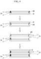
FIG. 4 illustrates a view for describing a method of forming the electrode assembly ofFIG. 2 andFIG. 3 . - As illustrated in
FIG. 4 , the fixingmember 200 may be formed by repeating processes of disposing thepositive electrode 20 on theseparator 30, forming the fixingmember 200 at the edge of theseparator 30, disposing theseparator 30 and thenegative electrode 10, and forming the fixingmember 200 at the edge of theseparator 30. In this case, the process of forming the fixingmember 200 includes a step of applying a solution adhesive to the edge and curing it. - The fixing
member 200 may be formed of a solution-type adhesive capable of thermosetting or UV curing and the fixingmember 200 may be a material having excellent adhesion to theseparator 30 but inferior adhesion to the metal sheets of the positive electrode and the negative electrode. The fixingmember 200 may include a polyolefin grafted with maleic anhydride. In this case, the polyolefin may be any one of polypropylene, polyethylene, and ethylene vinyl acetate (EVA). - The solution-type adhesive may be applied to the
separator 30, and then move along the first surface of theseparator 30. Therefore, after the solution-type adhesive is applied to the edge, viscosity and an amount of application of the solution-type adhesive are adjusted so as to not contact the end of the positive electrode or the negative electrode while moving along one surface of theseparator 30. - In addition, thermal curing or UV curing is rapidly performed after application to block the contact between the solution-type adhesive and the ends of the positive electrode and the negative electrode.
- On the other hand, the fixing
member 200 is formed at a regular interval along the edge of theseparator 30, and forms the fixingmember 200 to overlap at a same position. -
FIG. 5 illustrates a schematic cross-sectional view of an electrode assembly according to another exemplary embodiment of the present invention, which is taken along the line III-III ofFIG. 1 . - Since the electrode assemblies shown in
FIG. 5 are almost the same as those shown inFIG. 2 andFIG. 3 , only different parts will now be described in detail. - As illustrated in
FIG. 5 , anelectrode assembly 101 includes thepositive electrode 20 and thenegative electrode 10 that are repeatedly stacked with theseparator 30 interposed therebetween. Theseparator 30 is formed larger than thepositive electrode 20 and thenegative electrode 10, and a protruding edge thereof is fixed in contact with a fixingmember 201. - In this case, the fixing
member 201 may be formed to contact the end of theseparator 30 as well as the first surface of theseparators 30 facing each other. - The fixing
member 201 ofFIG. 2 andFIG. 3 is in contact with the first surface of theseparators 30 facing each other, while the fixingmember 201 ofFIG. 5 is in contact not only with the first surface of theseparators 30 facing each other, but also the end of theseparators 30, and thus the area between the fixingmember 201 and theseparator 30 is wider. - As such, as the area in which the
separator 30 and the fixingmember 201 come into contact with each other increases, the separators may be more firmly fixed, and thus the alignment of the stacked electrode assembly may be more effectively prevented from being misaligned. -
FIG. 6 illustrates a view for describing a method of forming the electrode assembly ofFIG. 5 . - As illustrated in
FIG. 6 , an electrode assembly in which thepositive electrode 20, theseparator 30, and thepositive electrode 10 are stacked is prepared, and the solution-type adhesive is applied to the end of theseparator 30 by using a nozzle-type applicator 300, and then is cured to form the fixingmember 201. - The fixing
member 201 may be a solution-type adhesive capable of thermosetting or UV curing, and the fixingmember 200 may be a material having excellent adhesion to theseparator 30 but inferior adhesion to the metal sheets of the positive electrode and the negative electrode. The fixingmember 201 may include a polyolefin grafted with maleic anhydride. In this case, the polyolefin may be any one of polypropylene, polyethylene, and ethylene vinyl acetate (EVA). - The solution-type adhesive may be applied to the
separator 30, and then move along the first surface of theseparator 30. Therefore, after the solution-type adhesive is applied to the edge, a concentration and an amount of application of the solution-type adhesive is adjusted so as to not contact the end of the positive electrode or the negative electrode while moving along one surface of theseparator 30. - In addition, thermal curing or UV curing is rapidly performed after application to prevent the contact between the solution-type adhesive and the ends of the positive electrode and the negative electrode.
- Meanwhile, since the fixing
member 201 is applied by using the nozzle-type applicator 300, the fixingmember 201 may be formed in a continuous linear shape in the direction Y across a sidewall of theelectrode assembly 101, but the present invention is not limited thereto, and it may be formed discontinuously (not illustrated) at a regular interval along the direction Y crossing the sidewall or a longitudinal direction X of the sidewall. -
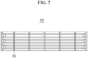
FIG. 7 to FIG. 10 illustrate views for describing a fixing member according to another embodiment of the present invention. - As illustrated in
FIG. 7 to FIG. 10 , a fixingmember 202 may be formed across the sidewall of anelectrode assembly - As illustrated in
FIG. 7 , the fixingmember 202 may be formed perpendicularly with respect to upper and lower surfaces of theelectrode assembly 102, or as illustrated inFIG. 8 andFIG. 9 , a fixingmember electrode assembly FIG. 10 , a fixingmember 205 may be formed to have a width W that is wider than that of the fixingmembers FIG. 7 to FIG. 9 . - In this case, an area corresponding to the sidewall is formed to be 95 % or less of a total sidewall area so that the fixing
members -
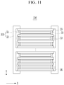
FIG. 11 illustrates a schematic cross-sectional view of an electrode assembly according to another exemplary embodiment of the present invention, which is taken along the line III-III ofFIG. 1 . - Since the electrode assemblies shown in
FIG. 11 are almost the same as those shown inFIG. 3 , only different parts will now be described in detail. - As illustrated in
FIG. 11 , anelectrode assembly 106 includes the positive electrode and the negative electrode that are repeatedly stacked with theseparator 30 interposed therebetween. Theseparator 30 is formed to be larger than the positive electrode and the negative electrode, and the fixingmember 206 is attached to a protruding edge thereof. - The fixing
member 206 may include an insulatingmember 22 and anadhesive layer 24. As illustrated inFIG. 5 , theadhesive layer 24 may be formed to contact the end of theseparator 30 as well as the first surface of theseparators 30 facing each other. - In addition, the insulating
member 22 may be formed to surround upper and lower surfaces of theelectrode assembly 106 together with theadhesive layer 24. Accordingly, upper and lower end portions of the insulatingmember 22 on which theadhesive layer 24 is not formed may have adhesiveness and may be attached to the upper and lower surfaces of theelectrode assembly 106. - As in the above embodiment, when the insulating
member 22 having adhesiveness is formed together with theadhesive layer 24, the insulatingmember 22 is attached to the upper and lower surfaces of theelectrode assembly 106 to fix the fixingmember 206 and the electrode, whereby an area contacted by theelectrode assembly 106 may be increased to more firmly maintain the alignment of theelectrode assembly 106. - The electrode assembly described in
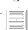
FIG. 11 may be formed by methods ofFIG. 12 andFIG. 13 . -
FIG. 12 andFIG. 13 illustrate views for describing a method of forming a fixing member in an electrode assembly according to another exemplary embodiment of the present invention. - As illustrated in
FIG. 12 , anelectrode assembly 107 in which the positive electrode, the separator, and the negative electrode are stacked and a fixingmember 207 are prepared. - The fixing
member 207 may include anadhesive layer 24 and an insulatingmember 22. The fixingmember 207 may have adhesiveness, and theadhesive layer 24 may be a hot melt adhesive that melts when a predetermined temperature is applied. Since the hot melt adhesive does not use an organic solvent, a risk due to the use of the organic solvent may be reduced. - The
adhesive layer 24 may include any one polymer selected from the group consisting of cellulose, polyvinylidene fluoride-cohexafluoropropylene, polyvinylidene fluoridecotrichloroethylene, polymethylmethacrylate, polybutylacrylate, polybutylacrylate acrylonitrile, polyvinylpyrrolidone, polyvinylacetate, ethylene vinyl co-vinyl acetate, polyethylene oxide, polyarylate, cellulose acetate, cellulose acetate butyrate, cellulose acetate propionate, cyanoethylpullulan, cyanoethylpolyvinylalcohol, cyanoethylcellulose, cyanoethylsucrose, pullulan, carboxyl methyl cellulose, or a maleic acid anhydride-polypropylene, or a mixture of two or more thereof, and preferably, may include polypropylene-maleic acid anhydride. - Thereafter, a fixing
member 207 is disposed so that theadhesive layer 22 is disposed on a sidewall of theelectrode assembly 107 and is heated to melt theadhesive layer 24, and then theadhesive layer 24 is adhered to the separator by removing the heat and curing it. In addition, theadhesive layer 24 may be adhered between adjacent separators while being cured by UV. - The
adhesive layer 24 may move to an end of the positive electrode or the negative electrode during curing depending on viscosity, and thus the thickness, viscosity, melting temperature, time, etc. of theadhesive layer 24 are adjusted so that theadhesive layer 24 does not come into contact with the ends of the positive electrode and the negative electrode even when theadhesive layer 24 moves between the separators. For example, theadhesive layer 24 may have viscosity of 500 cP or more. In the case of using heat, when theadhesive layer 24 is melted by heat to viscosity of 500 cP or more and then the heat is removed, theadhesive layer 24 may be cured before contacting the ends of the positive and negative electrodes. In addition, when UV is used, theadhesive layer 24 may be formed using an adhesive having viscosity of 500 cP to prevent the adhesive from moving during curing with UV. - In addition, referring to
FIG. 13 , the insulatingmember 22 having adhesiveness may be further attached onto an adhesive layer, which is the fixingmember 202 of theelectrode assembly 102 illustrated inFIG. 5 . - The above electrode assembly may be assembled as a rechargeable battery by being inserted into a can-shaped case (not illustrated) together with an electrolyte solution, and then sealing it with a cap plate connectable to an external terminal.
- While this invention has been described in connection with what is presently considered to be practical exemplary embodiments, it is to be understood that the invention is not limited to the disclosed embodiments, but, on the contrary, is intended to cover various modifications and equivalent arrangements included within the scope of the appended claims.
Claims (15)
- An electrode assembly comprising:a plurality of positive electrodes (10) and a plurality of negative electrodes (20), alternately and repeatedly stacked, each of the plurality of positive electrodes including an electrode region (1) and each of the plurality of negative including an electrode region (2);a plurality of separators (30), each separator being disposed between each of the plurality of positive electrodes and each of the plurality of negative electrodes to protrude from the electrode region of the positive electrode and the electrode region of the negative electrode and stacked such that a first surface of edges thereof face each other; anda fixing member (200) including an adhesive layer (24) adhered to the edges of each of the plurality of separators facing each other,wherein the adhesive layer (24) is spaced apart from ends of the electrode region (1, 2) of each of the plurality of positive electrodes or each of the plurality of negative electrodes.
- The electrode assembly of claim 1, wherein
the adhesive layer (24) is formed to surround ends of each of the separators. - The electrode assembly of claim 1 or 2, wherein
the fixing member further includes an insulating member (22) adhered to an upper surface of an uppermost separator and a lower surface of a lowermost separator (30). - The electrode assembly of claim 1, wherein
the adhesive layer (24) is formed at a regular interval along the edges of the plurality of separators (30). - The electrode assembly of any of claims 1 to 3, wherein
the adhesive layer (24) is connected to one another in a direction in which the separators overlap to form a linear shape. - The electrode assembly of claim 5, wherein
the adhesive layer (24) is inclined with respect to the overlapping direction. - The electrode assembly of one of preceding claims , wherein
the separator (30) is made of a polyolefin series, and
the fixing member (200) includes a polyolefin grafted with maleic anhydride. - A manufacturing method of the electrode assembly of any of claims 1 to 7, the method comprising steps of:forming an electrode assembly by repeatedly stacking a positive electrode (10), a separator (30), and a negative electrode (20);applying a solution-type adhesive to a sidewall of the electrode assembly; andforming an adhesive layer (24) by curing the solution-type adhesive,wherein the solution-type adhesive is applied in a direction in which separators (30) that are stacked overlap one another.
- The manufacturing method of claim 8, wherein
the adhesive layer(24) includes a plurality of adhesive layers, and they are formed at a regular interval. - The manufacturing method of claim 8 or 9, wherein
the adhesive layer is formed to have an area of 95 % or less with respect to an area of the sidewall. - The manufacturing method of claim 8 or 10, further comprising,
after the forming of the adhesive layer (24),
attaching an insulating member (22) onto the adhesive layer (22),
wherein the insulating member is attached to contact upper and lower surfaces of the electrode assembly. - The manufacturing method of one of claims 8 to 11, wherein,
the a positive electrode (10) and the negative electrode (20) include an electrode region (1, 3), respectively, and
in the step of the applying of the solution-type adhesive,
the solution-type adhesive is coated to be spaced apart from ends of electrode region (1, 3) of the positive electrode and the negative electrode. - The manufacturing method of one of claims 8 to 12, wherein,
in the step of the forming of the adhesive layer (24),
the curing includes thermosetting or UV curing. - A manufacturing method of the electrode assembly of any of claims 1 to 7, the method comprising steps of:forming an electrode assembly by repeatedly stacking a positive electrode (10), a separator (30), and a negative electrode (20);disposing a fixing member (200) including an adhesive layer (24) and an insulating member (22) on a sidewall of the electrode assembly; andmelting and then curing the adhesive layer (24),wherein the adhesive layer (24) includes a hot melt adhesive.
- The manufacturing method of claim 14, wherein
the fixing member (200) includes a plurality of fixing members, and they are disposed at a regular interval and/ or
wherein,
the a positive electrode (10) and the negative electrode (20) include an electrode region (1, 3), respectively, and
in the step of the curing,
the adhesive layer is spaced apart from ends of the electrode region (1, 3) of the positive electrode or the negative electrode.
Applications Claiming Priority (1)
| Application Number | Priority Date | Filing Date | Title |
|---|---|---|---|
| KR1020180142977A KR102164003B1 (en) | 2018-11-19 | 2018-11-19 | Electrode assembly and method of manufacturing the same |
Publications (2)
| Publication Number | Publication Date |
|---|---|
| EP3654409A1 true EP3654409A1 (en) | 2020-05-20 |
| EP3654409B1 EP3654409B1 (en) | 2022-10-26 |
Family
ID=68766463
Family Applications (1)
| Application Number | Title | Priority Date | Filing Date |
|---|---|---|---|
| EP19210077.4A Active EP3654409B1 (en) | 2018-11-19 | 2019-11-19 | Electrode assembly and method of manufacturing the same |
Country Status (6)
| Country | Link |
|---|---|
| US (3) | US11784378B2 (en) |
| EP (1) | EP3654409B1 (en) |
| KR (1) | KR102164003B1 (en) |
| CN (1) | CN111200156B (en) |
| HU (1) | HUE060766T2 (en) |
| PL (1) | PL3654409T3 (en) |
Cited By (3)
| Publication number | Priority date | Publication date | Assignee | Title |
|---|---|---|---|---|
| EP4195342A1 (en) * | 2021-11-23 | 2023-06-14 | Samsung SDI Co., Ltd. | Secondary battery |
| EP4318697A4 (en) * | 2021-12-06 | 2025-06-04 | Lg Energy Solution, Ltd. | Electrode assembly, manufacturing method therefor, and battery cell comprising same |
| EP4525113A3 (en) * | 2023-09-14 | 2025-06-04 | Samsung Sdi Co., Ltd. | Rechargeable battery |
Families Citing this family (12)
| Publication number | Priority date | Publication date | Assignee | Title |
|---|---|---|---|---|
| KR20220045353A (en) * | 2020-10-05 | 2022-04-12 | 현대자동차주식회사 | Battery module |
| CN116261794A (en) | 2020-11-18 | 2023-06-13 | 株式会社Lg新能源 | Secondary battery and manufacturing method thereof |
| JP7735635B2 (en) * | 2021-05-24 | 2025-09-09 | エルジー エナジー ソリューション リミテッド | Unit cell and battery cell including the same |
| EP4199235B1 (en) | 2021-05-24 | 2025-08-20 | LG Energy Solution, Ltd. | Unit cell and battery cell including the same |
| KR20230024796A (en) | 2021-08-12 | 2023-02-21 | 주식회사 엘지에너지솔루션 | Electrode assembly and manufacturing mehtod of the same |
| CN113594618B (en) * | 2021-08-16 | 2025-08-26 | 宁德新能源科技有限公司 | Battery packs and electrical equipment |
| ES3041563T3 (en) * | 2021-09-27 | 2025-11-12 | Lg Energy Solution Ltd | Electrode assembly and battery cell including the same |
| US20240283003A1 (en) * | 2021-10-07 | 2024-08-22 | Lg Energy Solution, Ltd. | Electrode Assembly and Battery Cell Including the Same |
| KR102784243B1 (en) | 2022-01-20 | 2025-03-21 | 삼성에스디아이 주식회사 | Secondary battery |
| JP2024535619A (en) * | 2022-05-10 | 2024-09-30 | エルジー エナジー ソリューション リミテッド | Electrode assembly, manufacturing method thereof, and battery cell including the same |
| JP2025043088A (en) * | 2023-09-15 | 2025-03-28 | トヨタ自動車株式会社 | Electrode laminate and battery |
| KR20250041449A (en) * | 2023-09-18 | 2025-03-25 | 삼성에스디아이 주식회사 | Electrode assembly and rechargeable battery including the same |
Citations (2)
| Publication number | Priority date | Publication date | Assignee | Title |
|---|---|---|---|---|
| US20080274394A1 (en) * | 2005-09-08 | 2008-11-06 | Evonik Degussa Gmbh | Stacks Of Separators And Electrodes Alternately Stacked One On Top Of The Other And Fixed For Li Storage Batteries |
| KR20160042748A (en) * | 2014-10-10 | 2016-04-20 | 삼성전자주식회사 | Flexible electrode assembly and electrochemical device having the electrode assembly |
Family Cites Families (28)
| Publication number | Priority date | Publication date | Assignee | Title |
|---|---|---|---|---|
| JP4564118B2 (en) | 1999-10-26 | 2010-10-20 | パナソニック株式会社 | Battery and manufacturing method thereof |
| US6433091B1 (en) * | 2001-05-10 | 2002-08-13 | Henkel Loctite Corporation | Adhesive composition |
| US7177137B2 (en) | 2002-04-15 | 2007-02-13 | Avx Corporation | Plated terminations |
| CN1799112A (en) | 2003-04-08 | 2006-07-05 | 阿维科斯公司 | Plating terminal |
| US20050137549A1 (en) * | 2003-12-22 | 2005-06-23 | Kimberly-Clark Worldwide, Inc. | Use of swirl-like adhesive patterns in the formation of absorbent articles |
| KR100579376B1 (en) | 2004-10-28 | 2006-05-12 | 삼성에스디아이 주식회사 | Secondary battery |
| KR100853619B1 (en) | 2006-01-04 | 2008-08-25 | 주식회사 엘지화학 | Electrode assembly is sealed the top of the separator and a secondary battery comprising the same |
| WO2008032367A1 (en) * | 2006-09-12 | 2008-03-20 | Nitto Denko Corporation | Dicing/die bonding film |
| JPWO2009130863A1 (en) | 2008-04-21 | 2011-08-11 | 株式会社村田製作所 | Multilayer piezoelectric actuator |
| KR101345446B1 (en) * | 2009-03-31 | 2013-12-27 | 미츠비시 쥬고교 가부시키가이샤 | Secondary Batteries and Battery Systems |
| JP5982131B2 (en) * | 2011-02-28 | 2016-08-31 | 日東電工株式会社 | Battery adhesive tape and battery using the adhesive tape |
| JP2012248465A (en) | 2011-05-30 | 2012-12-13 | Sharp Corp | Secondary battery and method of manufacturing the same |
| KR101905077B1 (en) | 2012-01-19 | 2018-10-05 | 삼성에스디아이 주식회사 | Reinforcing material for battery cell and battery cell using the same |
| WO2014014118A1 (en) * | 2012-07-18 | 2014-01-23 | 住友化学株式会社 | Adhesive layer, layer and composition |
| KR101578265B1 (en) | 2013-02-26 | 2015-12-16 | 주식회사 엘지화학 | Bi-cell for secondary battery with improved stability and manufacturing method thereof |
| KR101620173B1 (en) | 2013-07-10 | 2016-05-13 | 주식회사 엘지화학 | A stepwise electrode assembly with good stability and the method thereof |
| KR101598666B1 (en) | 2013-09-30 | 2016-03-02 | 주식회사 엘지화학 | Method of fixing electrode assembly using tape |
| KR101624386B1 (en) * | 2013-09-30 | 2016-05-25 | 주식회사 엘지화학 | Method of fixing electrode assembly using tape |
| KR101820442B1 (en) | 2013-10-31 | 2018-01-19 | 주식회사 엘지화학 | Device for Taping Electrode Assembly of Battery Cell and Battery Cell Manufactured Using the same |
| KR102153044B1 (en) * | 2013-11-11 | 2020-09-07 | 삼성전자주식회사 | Flexible secondary battery |
| KR101840859B1 (en) | 2013-11-18 | 2018-03-22 | 주식회사 엘지화학 | Apparatus for Attaching the Adhesion Member for Fixing Battery Assembly |
| KR102221807B1 (en) | 2014-08-11 | 2021-03-02 | 삼성에스디아이 주식회사 | Secondary battery |
| CN106797046B (en) * | 2014-08-25 | 2020-12-01 | 日产自动车株式会社 | Laminated battery and method of manufacturing the same |
| US9768421B2 (en) * | 2014-10-10 | 2017-09-19 | Samsung Electronics Co., Ltd. | Flexible electrode assembly and electrochemical device having the electrode assembly |
| KR101628892B1 (en) * | 2014-10-21 | 2016-06-09 | 주식회사 루트제이드 | Secondary battery having stepped cell structure |
| EP3139434B1 (en) | 2015-09-04 | 2018-02-28 | Renata AG | Coin cell and method for producing such coin cell |
| EP3211687B1 (en) * | 2016-02-24 | 2025-04-02 | Nitto Denko Corporation | Insulating tape |
| KR102152143B1 (en) * | 2016-11-24 | 2020-09-04 | 주식회사 엘지화학 | Electrode Assembly Comprising Separator Having Insulation-enhancing Part Formed on Edge Portion of Electrode |
-
2018
- 2018-11-19 KR KR1020180142977A patent/KR102164003B1/en active Active
-
2019
- 2019-11-13 US US16/682,229 patent/US11784378B2/en active Active
- 2019-11-18 CN CN201911125383.4A patent/CN111200156B/en active Active
- 2019-11-19 HU HUE19210077A patent/HUE060766T2/en unknown
- 2019-11-19 EP EP19210077.4A patent/EP3654409B1/en active Active
- 2019-11-19 PL PL19210077.4T patent/PL3654409T3/en unknown
-
2023
- 2023-06-28 US US18/343,274 patent/US12261323B2/en active Active
- 2023-07-24 US US18/357,696 patent/US12224453B2/en active Active
Patent Citations (2)
| Publication number | Priority date | Publication date | Assignee | Title |
|---|---|---|---|---|
| US20080274394A1 (en) * | 2005-09-08 | 2008-11-06 | Evonik Degussa Gmbh | Stacks Of Separators And Electrodes Alternately Stacked One On Top Of The Other And Fixed For Li Storage Batteries |
| KR20160042748A (en) * | 2014-10-10 | 2016-04-20 | 삼성전자주식회사 | Flexible electrode assembly and electrochemical device having the electrode assembly |
Cited By (3)
| Publication number | Priority date | Publication date | Assignee | Title |
|---|---|---|---|---|
| EP4195342A1 (en) * | 2021-11-23 | 2023-06-14 | Samsung SDI Co., Ltd. | Secondary battery |
| EP4318697A4 (en) * | 2021-12-06 | 2025-06-04 | Lg Energy Solution, Ltd. | Electrode assembly, manufacturing method therefor, and battery cell comprising same |
| EP4525113A3 (en) * | 2023-09-14 | 2025-06-04 | Samsung Sdi Co., Ltd. | Rechargeable battery |
Also Published As
| Publication number | Publication date |
|---|---|
| US11784378B2 (en) | 2023-10-10 |
| US12224453B2 (en) | 2025-02-11 |
| HUE060766T2 (en) | 2023-04-28 |
| EP3654409B1 (en) | 2022-10-26 |
| KR20200058222A (en) | 2020-05-27 |
| PL3654409T3 (en) | 2023-01-09 |
| KR102164003B1 (en) | 2020-10-12 |
| US20230335864A1 (en) | 2023-10-19 |
| US20230369720A1 (en) | 2023-11-16 |
| US20200161617A1 (en) | 2020-05-21 |
| CN111200156B (en) | 2023-12-22 |
| US12261323B2 (en) | 2025-03-25 |
| CN111200156A (en) | 2020-05-26 |
Similar Documents
| Publication | Publication Date | Title |
|---|---|---|
| US12224453B2 (en) | Electrode assembly and method of manufacturing the same | |
| JP6788107B2 (en) | Manufacturing method of electrode unit for battery cell and electrode unit | |
| US10923758B2 (en) | Electrode assembly having step, secondary battery, battery pack and device including electrode assembly, and method of manufacturing electrode assembly | |
| CN110071322B (en) | Secondary battery and method for manufacturing same | |
| KR102085342B1 (en) | An electrode lead for a secondary battery, a pouch type secondary battery and a battery module comprising the same | |
| EP2985812B1 (en) | Secondary battery | |
| US20110195298A1 (en) | Stacked secondary battery | |
| KR102207132B1 (en) | Electrode Assembly for Battery Cell Comprising Sealed Separator | |
| US10454131B2 (en) | Secondary battery, apparatus for manufacturing the same, and method of manufacturing the same | |
| KR20180057847A (en) | Apparatus of manufacturing electrode assembly and method of manufacturing electrode assembly using the same | |
| KR102446279B1 (en) | Electrode assembly manufacturing method and secondary battery manufacturing method | |
| WO2018080080A1 (en) | Secondary battery | |
| US20230299433A1 (en) | Method for Welding Electrode Assembly | |
| KR20220016554A (en) | Electrode assembly including disconnection preventing layer and method for manufacturing the same | |
| KR101425257B1 (en) | Electrode assembly and secondary battery using the same | |
| KR101790230B1 (en) | Battery Cell Having Electrode Terminal Coated with Insulation Coating Layer | |
| US12224392B2 (en) | Electrode assembly and method of manufacturing the same | |
| KR101755073B1 (en) | Secondary battery and method for manufacture the same | |
| KR20230114119A (en) | Electrode assembly manufacturing method | |
| US20230163416A1 (en) | Secondary battery | |
| KR20220100333A (en) | Unit cell for secondary battery including seperator with insulating coating layer and manufacturing method thereof | |
| KR102961343B1 (en) | Method for manufacturing an electrode | |
| US20250316798A1 (en) | Secondary battery | |
| US20250170816A1 (en) | Method for disassembling electrode body | |
| CN118285005A (en) | Stacked folding type electrode assembly having thickness supplementing unit, manufacturing method thereof, and secondary battery including the stacked folding type electrode assembly |
Legal Events
| Date | Code | Title | Description |
|---|---|---|---|
| PUAI | Public reference made under article 153(3) epc to a published international application that has entered the european phase |
Free format text: ORIGINAL CODE: 0009012 |
|
| STAA | Information on the status of an ep patent application or granted ep patent |
Free format text: STATUS: REQUEST FOR EXAMINATION WAS MADE |
|
| 17P | Request for examination filed |
Effective date: 20191119 |
|
| AK | Designated contracting states |
Kind code of ref document: A1 Designated state(s): AL AT BE BG CH CY CZ DE DK EE ES FI FR GB GR HR HU IE IS IT LI LT LU LV MC MK MT NL NO PL PT RO RS SE SI SK SM TR |
|
| AX | Request for extension of the european patent |
Extension state: BA ME |
|
| RIC1 | Information provided on ipc code assigned before grant |
Ipc: H01M 50/46 20210101ALI20210927BHEP Ipc: H01M 50/183 20210101ALI20210927BHEP Ipc: H01M 50/409 20210101ALI20210927BHEP Ipc: H01M 10/0585 20100101ALI20210927BHEP Ipc: H01M 10/052 20100101ALI20210927BHEP Ipc: H01M 10/04 20060101ALI20210927BHEP Ipc: H01M 4/04 20060101AFI20210927BHEP |
|
| GRAP | Despatch of communication of intention to grant a patent |
Free format text: ORIGINAL CODE: EPIDOSNIGR1 |
|
| STAA | Information on the status of an ep patent application or granted ep patent |
Free format text: STATUS: GRANT OF PATENT IS INTENDED |
|
| INTG | Intention to grant announced |
Effective date: 20211116 |
|
| GRAJ | Information related to disapproval of communication of intention to grant by the applicant or resumption of examination proceedings by the epo deleted |
Free format text: ORIGINAL CODE: EPIDOSDIGR1 |
|
| STAA | Information on the status of an ep patent application or granted ep patent |
Free format text: STATUS: REQUEST FOR EXAMINATION WAS MADE |
|
| REG | Reference to a national code |
Ref country code: DE Ref legal event code: R079 Ref document number: 602019021041 Country of ref document: DE Free format text: PREVIOUS MAIN CLASS: H01M0002160000 Ipc: H01M0004040000 |
|
| INTC | Intention to grant announced (deleted) | ||
| RIC1 | Information provided on ipc code assigned before grant |
Ipc: H01M 50/417 20210101ALI20220322BHEP Ipc: H01M 50/46 20210101ALI20220322BHEP Ipc: H01M 50/183 20210101ALI20220322BHEP Ipc: H01M 50/409 20210101ALI20220322BHEP Ipc: H01M 10/0585 20100101ALI20220322BHEP Ipc: H01M 10/052 20100101ALI20220322BHEP Ipc: H01M 10/04 20060101ALI20220322BHEP Ipc: H01M 4/04 20060101AFI20220322BHEP |
|
| GRAP | Despatch of communication of intention to grant a patent |
Free format text: ORIGINAL CODE: EPIDOSNIGR1 |
|
| STAA | Information on the status of an ep patent application or granted ep patent |
Free format text: STATUS: GRANT OF PATENT IS INTENDED |
|
| INTG | Intention to grant announced |
Effective date: 20220520 |
|
| GRAS | Grant fee paid |
Free format text: ORIGINAL CODE: EPIDOSNIGR3 |
|
| GRAA | (expected) grant |
Free format text: ORIGINAL CODE: 0009210 |
|
| STAA | Information on the status of an ep patent application or granted ep patent |
Free format text: STATUS: THE PATENT HAS BEEN GRANTED |
|
| AK | Designated contracting states |
Kind code of ref document: B1 Designated state(s): AL AT BE BG CH CY CZ DE DK EE ES FI FR GB GR HR HU IE IS IT LI LT LU LV MC MK MT NL NO PL PT RO RS SE SI SK SM TR |
|
| REG | Reference to a national code |
Ref country code: GB Ref legal event code: FG4D |
|
| REG | Reference to a national code |
Ref country code: CH Ref legal event code: EP |
|
| REG | Reference to a national code |
Ref country code: AT Ref legal event code: REF Ref document number: 1527706 Country of ref document: AT Kind code of ref document: T Effective date: 20221115 |
|
| REG | Reference to a national code |
Ref country code: DE Ref legal event code: R096 Ref document number: 602019021041 Country of ref document: DE |
|
| REG | Reference to a national code |
Ref country code: IE Ref legal event code: FG4D |
|
| REG | Reference to a national code |
Ref country code: SE Ref legal event code: TRGR |
|
| REG | Reference to a national code |
Ref country code: LT Ref legal event code: MG9D |
|
| REG | Reference to a national code |
Ref country code: NL Ref legal event code: MP Effective date: 20221026 |
|
| REG | Reference to a national code |
Ref country code: AT Ref legal event code: MK05 Ref document number: 1527706 Country of ref document: AT Kind code of ref document: T Effective date: 20221026 |
|
| PG25 | Lapsed in a contracting state [announced via postgrant information from national office to epo] |
Ref country code: NL Free format text: LAPSE BECAUSE OF FAILURE TO SUBMIT A TRANSLATION OF THE DESCRIPTION OR TO PAY THE FEE WITHIN THE PRESCRIBED TIME-LIMIT Effective date: 20221026 |
|
| PG25 | Lapsed in a contracting state [announced via postgrant information from national office to epo] |
Ref country code: PT Free format text: LAPSE BECAUSE OF FAILURE TO SUBMIT A TRANSLATION OF THE DESCRIPTION OR TO PAY THE FEE WITHIN THE PRESCRIBED TIME-LIMIT Effective date: 20230227 Ref country code: NO Free format text: LAPSE BECAUSE OF FAILURE TO SUBMIT A TRANSLATION OF THE DESCRIPTION OR TO PAY THE FEE WITHIN THE PRESCRIBED TIME-LIMIT Effective date: 20230126 Ref country code: LT Free format text: LAPSE BECAUSE OF FAILURE TO SUBMIT A TRANSLATION OF THE DESCRIPTION OR TO PAY THE FEE WITHIN THE PRESCRIBED TIME-LIMIT Effective date: 20221026 Ref country code: FI Free format text: LAPSE BECAUSE OF FAILURE TO SUBMIT A TRANSLATION OF THE DESCRIPTION OR TO PAY THE FEE WITHIN THE PRESCRIBED TIME-LIMIT Effective date: 20221026 Ref country code: ES Free format text: LAPSE BECAUSE OF FAILURE TO SUBMIT A TRANSLATION OF THE DESCRIPTION OR TO PAY THE FEE WITHIN THE PRESCRIBED TIME-LIMIT Effective date: 20221026 Ref country code: AT Free format text: LAPSE BECAUSE OF FAILURE TO SUBMIT A TRANSLATION OF THE DESCRIPTION OR TO PAY THE FEE WITHIN THE PRESCRIBED TIME-LIMIT Effective date: 20221026 |
|
| REG | Reference to a national code |
Ref country code: HU Ref legal event code: AG4A Ref document number: E060766 Country of ref document: HU |
|
| PG25 | Lapsed in a contracting state [announced via postgrant information from national office to epo] |
Ref country code: RS Free format text: LAPSE BECAUSE OF FAILURE TO SUBMIT A TRANSLATION OF THE DESCRIPTION OR TO PAY THE FEE WITHIN THE PRESCRIBED TIME-LIMIT Effective date: 20221026 Ref country code: LV Free format text: LAPSE BECAUSE OF FAILURE TO SUBMIT A TRANSLATION OF THE DESCRIPTION OR TO PAY THE FEE WITHIN THE PRESCRIBED TIME-LIMIT Effective date: 20221026 Ref country code: IS Free format text: LAPSE BECAUSE OF FAILURE TO SUBMIT A TRANSLATION OF THE DESCRIPTION OR TO PAY THE FEE WITHIN THE PRESCRIBED TIME-LIMIT Effective date: 20230226 Ref country code: HR Free format text: LAPSE BECAUSE OF FAILURE TO SUBMIT A TRANSLATION OF THE DESCRIPTION OR TO PAY THE FEE WITHIN THE PRESCRIBED TIME-LIMIT Effective date: 20221026 Ref country code: GR Free format text: LAPSE BECAUSE OF FAILURE TO SUBMIT A TRANSLATION OF THE DESCRIPTION OR TO PAY THE FEE WITHIN THE PRESCRIBED TIME-LIMIT Effective date: 20230127 |
|
| REG | Reference to a national code |
Ref country code: CH Ref legal event code: PL |
|
| P01 | Opt-out of the competence of the unified patent court (upc) registered |
Effective date: 20230528 |
|
| REG | Reference to a national code |
Ref country code: DE Ref legal event code: R097 Ref document number: 602019021041 Country of ref document: DE Ref country code: BE Ref legal event code: MM Effective date: 20221130 |
|
| PG25 | Lapsed in a contracting state [announced via postgrant information from national office to epo] |
Ref country code: SM Free format text: LAPSE BECAUSE OF FAILURE TO SUBMIT A TRANSLATION OF THE DESCRIPTION OR TO PAY THE FEE WITHIN THE PRESCRIBED TIME-LIMIT Effective date: 20221026 Ref country code: RO Free format text: LAPSE BECAUSE OF FAILURE TO SUBMIT A TRANSLATION OF THE DESCRIPTION OR TO PAY THE FEE WITHIN THE PRESCRIBED TIME-LIMIT Effective date: 20221026 Ref country code: MC Free format text: LAPSE BECAUSE OF FAILURE TO SUBMIT A TRANSLATION OF THE DESCRIPTION OR TO PAY THE FEE WITHIN THE PRESCRIBED TIME-LIMIT Effective date: 20221026 Ref country code: LI Free format text: LAPSE BECAUSE OF NON-PAYMENT OF DUE FEES Effective date: 20221130 Ref country code: EE Free format text: LAPSE BECAUSE OF FAILURE TO SUBMIT A TRANSLATION OF THE DESCRIPTION OR TO PAY THE FEE WITHIN THE PRESCRIBED TIME-LIMIT Effective date: 20221026 Ref country code: DK Free format text: LAPSE BECAUSE OF FAILURE TO SUBMIT A TRANSLATION OF THE DESCRIPTION OR TO PAY THE FEE WITHIN THE PRESCRIBED TIME-LIMIT Effective date: 20221026 Ref country code: CZ Free format text: LAPSE BECAUSE OF FAILURE TO SUBMIT A TRANSLATION OF THE DESCRIPTION OR TO PAY THE FEE WITHIN THE PRESCRIBED TIME-LIMIT Effective date: 20221026 Ref country code: CH Free format text: LAPSE BECAUSE OF NON-PAYMENT OF DUE FEES Effective date: 20221130 |
|
| PG25 | Lapsed in a contracting state [announced via postgrant information from national office to epo] |
Ref country code: SK Free format text: LAPSE BECAUSE OF FAILURE TO SUBMIT A TRANSLATION OF THE DESCRIPTION OR TO PAY THE FEE WITHIN THE PRESCRIBED TIME-LIMIT Effective date: 20221026 Ref country code: LU Free format text: LAPSE BECAUSE OF NON-PAYMENT OF DUE FEES Effective date: 20221119 Ref country code: AL Free format text: LAPSE BECAUSE OF FAILURE TO SUBMIT A TRANSLATION OF THE DESCRIPTION OR TO PAY THE FEE WITHIN THE PRESCRIBED TIME-LIMIT Effective date: 20221026 |
|
| PLBE | No opposition filed within time limit |
Free format text: ORIGINAL CODE: 0009261 |
|
| STAA | Information on the status of an ep patent application or granted ep patent |
Free format text: STATUS: NO OPPOSITION FILED WITHIN TIME LIMIT |
|
| 26N | No opposition filed |
Effective date: 20230727 |
|
| PG25 | Lapsed in a contracting state [announced via postgrant information from national office to epo] |
Ref country code: IE Free format text: LAPSE BECAUSE OF NON-PAYMENT OF DUE FEES Effective date: 20221119 |
|
| PG25 | Lapsed in a contracting state [announced via postgrant information from national office to epo] |
Ref country code: SI Free format text: LAPSE BECAUSE OF FAILURE TO SUBMIT A TRANSLATION OF THE DESCRIPTION OR TO PAY THE FEE WITHIN THE PRESCRIBED TIME-LIMIT Effective date: 20221026 Ref country code: BE Free format text: LAPSE BECAUSE OF NON-PAYMENT OF DUE FEES Effective date: 20221130 |
|
| PG25 | Lapsed in a contracting state [announced via postgrant information from national office to epo] |
Ref country code: CY Free format text: LAPSE BECAUSE OF FAILURE TO SUBMIT A TRANSLATION OF THE DESCRIPTION OR TO PAY THE FEE WITHIN THE PRESCRIBED TIME-LIMIT Effective date: 20221026 |
|
| PG25 | Lapsed in a contracting state [announced via postgrant information from national office to epo] |
Ref country code: MK Free format text: LAPSE BECAUSE OF FAILURE TO SUBMIT A TRANSLATION OF THE DESCRIPTION OR TO PAY THE FEE WITHIN THE PRESCRIBED TIME-LIMIT Effective date: 20221026 Ref country code: IT Free format text: LAPSE BECAUSE OF FAILURE TO SUBMIT A TRANSLATION OF THE DESCRIPTION OR TO PAY THE FEE WITHIN THE PRESCRIBED TIME-LIMIT Effective date: 20221026 |
|
| PG25 | Lapsed in a contracting state [announced via postgrant information from national office to epo] |
Ref country code: TR Free format text: LAPSE BECAUSE OF FAILURE TO SUBMIT A TRANSLATION OF THE DESCRIPTION OR TO PAY THE FEE WITHIN THE PRESCRIBED TIME-LIMIT Effective date: 20221026 |
|
| PG25 | Lapsed in a contracting state [announced via postgrant information from national office to epo] |
Ref country code: BG Free format text: LAPSE BECAUSE OF FAILURE TO SUBMIT A TRANSLATION OF THE DESCRIPTION OR TO PAY THE FEE WITHIN THE PRESCRIBED TIME-LIMIT Effective date: 20221026 |
|
| PG25 | Lapsed in a contracting state [announced via postgrant information from national office to epo] |
Ref country code: MT Free format text: LAPSE BECAUSE OF FAILURE TO SUBMIT A TRANSLATION OF THE DESCRIPTION OR TO PAY THE FEE WITHIN THE PRESCRIBED TIME-LIMIT Effective date: 20221026 |
|
| PGFP | Annual fee paid to national office [announced via postgrant information from national office to epo] |
Ref country code: HU Payment date: 20251127 Year of fee payment: 7 |
|
| PGFP | Annual fee paid to national office [announced via postgrant information from national office to epo] |
Ref country code: DE Payment date: 20251104 Year of fee payment: 7 |
|
| PGFP | Annual fee paid to national office [announced via postgrant information from national office to epo] |
Ref country code: GB Payment date: 20251030 Year of fee payment: 7 |
|
| PGFP | Annual fee paid to national office [announced via postgrant information from national office to epo] |
Ref country code: FR Payment date: 20251117 Year of fee payment: 7 |
|
| PGFP | Annual fee paid to national office [announced via postgrant information from national office to epo] |
Ref country code: SE Payment date: 20251112 Year of fee payment: 7 |
|
| PGFP | Annual fee paid to national office [announced via postgrant information from national office to epo] |
Ref country code: PL Payment date: 20251103 Year of fee payment: 7 |