EP3654279A1 - Object identification system - Google Patents
Object identification system Download PDFInfo
- Publication number
- EP3654279A1 EP3654279A1 EP18831870.3A EP18831870A EP3654279A1 EP 3654279 A1 EP3654279 A1 EP 3654279A1 EP 18831870 A EP18831870 A EP 18831870A EP 3654279 A1 EP3654279 A1 EP 3654279A1
- Authority
- EP
- European Patent Office
- Prior art keywords
- identification
- information
- control unit
- server
- image
- Prior art date
- Legal status (The legal status is an assumption and is not a legal conclusion. Google has not performed a legal analysis and makes no representation as to the accuracy of the status listed.)
- Pending
Links
Images





Classifications
-
- G—PHYSICS
- G06—COMPUTING OR CALCULATING; COUNTING
- G06V—IMAGE OR VIDEO RECOGNITION OR UNDERSTANDING
- G06V20/00—Scenes; Scene-specific elements
- G06V20/50—Context or environment of the image
- G06V20/52—Surveillance or monitoring of activities, e.g. for recognising suspicious objects
-
- G—PHYSICS
- G06—COMPUTING OR CALCULATING; COUNTING
- G06Q—INFORMATION AND COMMUNICATION TECHNOLOGY [ICT] SPECIALLY ADAPTED FOR ADMINISTRATIVE, COMMERCIAL, FINANCIAL, MANAGERIAL OR SUPERVISORY PURPOSES; SYSTEMS OR METHODS SPECIALLY ADAPTED FOR ADMINISTRATIVE, COMMERCIAL, FINANCIAL, MANAGERIAL OR SUPERVISORY PURPOSES, NOT OTHERWISE PROVIDED FOR
- G06Q10/00—Administration; Management
- G06Q10/20—Administration of product repair or maintenance
-
- G—PHYSICS
- G06—COMPUTING OR CALCULATING; COUNTING
- G06T—IMAGE DATA PROCESSING OR GENERATION, IN GENERAL
- G06T7/00—Image analysis
- G06T7/10—Segmentation; Edge detection
- G06T7/11—Region-based segmentation
-
- G—PHYSICS
- G06—COMPUTING OR CALCULATING; COUNTING
- G06T—IMAGE DATA PROCESSING OR GENERATION, IN GENERAL
- G06T7/00—Image analysis
- G06T7/70—Determining position or orientation of objects or cameras
-
- G—PHYSICS
- G06—COMPUTING OR CALCULATING; COUNTING
- G06V—IMAGE OR VIDEO RECOGNITION OR UNDERSTANDING
- G06V10/00—Arrangements for image or video recognition or understanding
- G06V10/40—Extraction of image or video features
-
- G—PHYSICS
- G06—COMPUTING OR CALCULATING; COUNTING
- G06V—IMAGE OR VIDEO RECOGNITION OR UNDERSTANDING
- G06V20/00—Scenes; Scene-specific elements
- G06V20/20—Scenes; Scene-specific elements in augmented reality scenes
-
- H—ELECTRICITY
- H04—ELECTRIC COMMUNICATION TECHNIQUE
- H04N—PICTORIAL COMMUNICATION, e.g. TELEVISION
- H04N23/00—Cameras or camera modules comprising electronic image sensors; Control thereof
- H04N23/60—Control of cameras or camera modules
-
- G—PHYSICS
- G06—COMPUTING OR CALCULATING; COUNTING
- G06V—IMAGE OR VIDEO RECOGNITION OR UNDERSTANDING
- G06V2201/00—Indexing scheme relating to image or video recognition or understanding
- G06V2201/08—Detecting or categorising vehicles
Definitions
- the present invention relates to an object identification system.
- Patent Literature 1 discloses an object identification system including a terminal device with a camera and a server communicable with the terminal device. Specifically, the terminal device transmits an image (input image) captured by the camera to the server. The server extracts a feature quantity from the image received from the terminal device, and compares the extracted feature quantity with a first feature quantity dictionary to identify an object in the received image. Thereafter, in accordance with the result of the identification, the server obtains a second feature quantity dictionary and additional information that are to be supplied to the terminal device. Then, the server transmits the second feature quantity dictionary and the additional information to the terminal device. The quantity of data included in the second feature quantity dictionary is smaller than that of the first feature quantity dictionary.
- the terminal device extracts a feature quantity from an input image, and compares the extracted feature quantity with the second feature quantity dictionary obtained from the server. In this manner, the terminal device identifies an object in the input image. Next, the terminal device obtains additional information related to the identified object from an additional information database obtained from the server, and superimposes the obtained additional information on the input image, so as to generate an output image. Then, the terminal device displays the output image on a display unit.
- the terminal device compares a feature quantity of an input image with the second feature quantity dictionary obtained from the server to identify an object in the input image.
- the terminal device compares a feature quantity of an input image with the second feature quantity dictionary obtained from the server to identify an object in the input image.
- a plurality of vehicles of the same model e.g., a plurality of work vehicles, it is difficult to identify a work vehicle at an individual level based on a feature quantity of the work vehicle in an input image.
- the present invention has an object to provide an object identification system capable of identifying an identification target at an individual level by capturing an image of the identification target with a terminal device, even in a case where there exists a plurality of identification objects including two or more identification objects having the identical feature information.
- An object identification system of the present invention includes:
- the identification object refers to an object that can be a target to be identified by the object identification system of the present invention.
- the identification target refers to, among the identification objects, a target to be identified distinctively from the others.
- an image of an identification target is captured by the image capturing unit of the terminal device, and feature information of the identification target is extracted therefrom. Then, identification and judgment information including the feature information of the identification target and the terminal position information is transmitted to the server.
- the server determines a search area based on the terminal position information, and searches for an identification object satisfying a condition of existing within the search area thus determined and having feature information identical to the feature information included in the identification and judgment information (i.e., the feature information of the identification target). If the identification object satisfying the condition is found, the identification object is identified as the identification target.
- the server-side identification control unit identifies, as the identification target, one of the predetermined identification objects located closer to the terminal device than any other predetermined identification objects.
- pieces of feature information, pieces of position information, and pieces of individual information of the identification objects are stored respectively in association with the identification objects, and in a case where the server-side identification control unit identifies the predetermined identification object as the identification target, the server-side identification control unit transmits, to the terminal device, a piece of individual information associated with the predetermined identification object from among the pieces of individual information stored in the memory unit.
- the server can transmit, to the terminal device, the individual information of the identification object having been identified as the identification target.
- the terminal device further includes a display unit configured to display thereon the image captured by the image capturing unit, and the terminal-side identification control unit displays the piece of individual information from the server-side identification control unit in such a manner that the piece of individual information is superimposed on the image displayed on the display unit.
- a user of the terminal device can recognize the individual information of the identification target.
- each of the pieces of individual information includes at least one of a piece of identification information used to identify a corresponding one of the identification objects, a piece of operation information of the corresponding one of the identification objects, and a piece of maintenance information of the corresponding one of the identification objects.
- the user of the terminal device can recognize at least one of the identification information, the operation information, and the maintenance information of the identification target.
- each of the pieces of individual information includes a piece of defective component identification information indicating a defective component of a corresponding one of the identification objects, and, based on a piece of defective component identification information included in the piece of individual information from the server-side identification control unit, the terminal-side identification control unit displays an image of a defective component corresponding to the piece of defective component identification information in such a manner that the image of the defective component is superimposed on the image displayed on the display unit.
- the user of the terminal device can visually recognize a defective portion.
- the feature information is model information of a corresponding one of the identification objects.
- FIG. 1 is a view schematically illustrating a configuration of a work vehicle identification system including an object identification system according to an embodiment of the present invention.
- FIG. 1 is a view schematically illustrating a configuration of a work vehicle identification system including an object identification system according to an embodiment of the present invention.
- a work vehicle identification system 1 is a system for identifying, at an individual level, a work vehicle 2 that is an identification object.
- the work vehicle identification system 1 includes a portable terminal device (hereinafter, referred to as a "terminal device 3") and a remote monitoring server 4.
- the work vehicle 2 is communicable with the remote monitoring server 4 over a communication network 6.
- the work vehicle 2 has a function to measure its own position via a positioning satellite 7.
- the work vehicle 2 has a lateral side on which model information 9 indicating the model of the work vehicle 2 is exhibited.
- the model information 9 of the work vehicle 2 illustrated in FIG. 1 is "YH448".
- the model information 9 is one example of the feature information of the identification object.
- the portable terminal 3 is a portable terminal such as a smartphone or a tablet-type personal computer (tablet PC).
- the portable terminal 3 is a smartphone.
- the portable terminal 3 includes an image capturing unit 53 (see FIG. 6 ), such as a charge-coupled device (CCD) camera.
- the portable terminal 3 has a function to measure its own position via the positioning satellite 7.
- the portable terminal 3 has a vehicle identification/information adding program developed to implement the present embodiment.
- the vehicle identification/information adding program is an application program for identifying the work vehicle 2 in cooperation with the remote monitoring server 4 and adding information to a captured image through AR.
- AR is a technique called "augmented reality", and is used to extend the real world by displaying additional information on the real world.
- the portable terminal 3 is communicable with the remote monitoring server 4 over the communication network 6. In this embodiment, when maintenance is conducted, the portable terminal 3 is carried by, e.g., a serviceman who is in charge of the maintenance of the work vehicle 2.
- the remote monitoring server 4 is a server provided in a remote monitoring center 5 and configured to remotely monitor a plurality of work vehicles 2.
- the remote monitoring server 4 is communicable with the work vehicles 2 and the portable terminal 3 over the communication network 6.
- the work vehicle 2 transmits, to the remote monitoring server 4, information such as identification information, position information, operation information, and/or error detection information (abnormality information) of the work vehicle 2.
- the identification information of the work vehicle 2 transmitted from the work vehicle 2 to the remote monitoring server 4 is a phone number of a remote monitoring terminal 12 (see FIG. 2 ) provided in the work vehicle 2, as will be described later.
- the identification information may alternatively be a machine number that is identification information uniquely allocated to the work vehicle 2.
- the remote monitoring server 4 Upon reception of the information such as the identification information, the position information, the operation information, and/or the error detection information from one of the work vehicles 2, the remote monitoring server 4 stores these pieces of information therein in association with the identification information, the model information, and the machine number of the one of the work vehicles 2. In a case where the remote monitoring server 4 has received the error detection information from the work vehicle 2, the remote monitoring server 4 notifies the serviceman of the error directly or via an operator. The serviceman who carries the portable terminal 3 goes to a place where the work vehicle 2 having the error resides. In the following description, the work vehicle 2 having the error may be referred to as an "error vehicle" occasionally.
- the serviceman When the serviceman arrives at the place where the error vehicle resides, the serviceman operates the portable terminal 3 to start the vehicle identification/information adding program.
- the image capturing unit 53 When the vehicle identification/information adding program is started, the image capturing unit 53 is activated. Then, the serviceman sets an image capturing direction of the portable terminal 3 toward the lateral side of the error vehicle (identification target). More specifically, the serviceman directs the portable terminal 3 toward the error vehicle to capture an image of the lateral side of the error vehicle on which the model information 9 is exhibited. Consequently, the image including the error vehicle is ready to be inputted from the image capturing unit 53 to the portable terminal 3.
- the portable terminal 3 extracts the model information 9 from the input image. Then, the portable terminal 3 transmits, to the remote monitoring server 4, identification and judgment information including the extracted model information 9 and the position information of the portable terminal 3 (which may include the information indicating the posture and orientation of the portable terminal 3).
- the remote monitoring server 4 Upon reception of the identification and judgment information from the portable terminal 3, the remote monitoring server 4 determines a search area at a location close to the portable terminal 3, based on the position information included in the identification and judgment information. Next, based on the pieces of latest position information of the plurality of work vehicles 2, the remote monitoring server 4 searches for a work vehicle 2 satisfying a condition of existing within the search area and being labeled with the model identical to that indicated by the model information 9 included in the identification and judgment information. If the remote monitoring server 4 finds a work vehicle 2 satisfying the condition, the remote monitoring server 4 identifies the work vehicle 2 as the error vehicle (identification target), and transmits information (hereinafter, referred to as "individual information") about the work vehicle 2 to the portable terminal 3.
- the portable terminal 3 Upon reception of the individual information, the portable terminal 3 displays predetermined information included in the individual information in such a manner that the predetermined information is superimposed on the input image, or displays an image (e.g., a component image) corresponding to the predetermined information included in the individual information in such a manner that the image is superimposed on the input image.
- predetermined information included in the individual information in such a manner that the predetermined information is superimposed on the input image, or displays an image (e.g., a component image) corresponding to the predetermined information included in the individual information in such a manner that the image is superimposed on the input image.
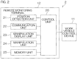
- FIG. 2 is a block diagram showing a main electric structure of the work vehicle 2.
- the work vehicle 2 includes a work vehicle control device 11 and a remote monitoring terminal 12.
- the work vehicle control device 11 controls electric components in various parts of the work vehicle 2.
- the work vehicle control device 11 controls electric components in various parts of the combine harvester, such as a traveling device, a reaping device, a carrying device, and a threshing device.
- the work vehicle control device 11 provides the remote monitoring terminal 12 with information such as the operation information and the error detection information of the work vehicle 2.
- the operation information encompass an operating period, an engine speed, an exhaust gas temperature, a manipulation state of an accelerator, and a manipulation state of a brake.
- the error detection information includes an error code indicating a type of an error.
- the remote monitoring terminal 12 transmits, to the remote monitoring server 4, information such as the position information of the work vehicle 2 as well as the operation information and the error detection information supplied from the work vehicle control device 11.
- the remote monitoring terminal 12 has a phone number for communication.
- the remote monitoring terminal 12 has a control unit 20.
- the control unit 20 is connected to, e.g., a position detection unit 21, a communication unit 22, a manipulation display unit 23, a manipulation unit 24, and a memory unit 25.
- the position detection unit 21 is configured to calculate position information of the remote monitoring terminal 12 through a satellite positioning system.
- the satellite positioning system is global navigation satellite system (GNSS).
- GNSS global navigation satellite system
- the position detection unit 21 receives satellite signals from the plurality of positioning satellites 7 (see FIG. 1 ), and calculates the position information of the remote monitoring terminal 12 (work vehicle 2).
- the position information includes information indicative of a latitude, a longitude, and an altitude, for example.
- the communication unit 22 is a communication interface via which the control unit 20 communicates with the remote monitoring server 4 over the communication network 6.
- the manipulation display unit 23 is made of a touch panel display, for example.
- the manipulation unit 24 includes one or more manipulation buttons, for example.
- the memory unit 25 is made of a storage device such as a nonvolatile memory.
- the control unit 20 includes a microcomputer having a central processing unit (CPU) and a memory (e.g., a ROM, a RAM).
- the control unit 20 obtains, at every predetermined period, the position information calculated by the position detection unit 21, and stores the position information in the memory unit 25. Then, the control unit 20 transmits, at every predetermined period, the latest position information stored in the memory unit 25 to the remote monitoring server 4.
- the control unit 20 accumulates, in the memory unit 25, the operation information supplied from the work vehicle control device 11. Then, at a predetermined timing (e.g., at a timing when a manipulation for turning off the power is performed), the control unit 20 transmits the operation information accumulated in the memory unit 25 to the remote monitoring server 4 in a batch. When the control unit 20 receives the error detection information from the work vehicle control device 11, the control unit 20 stores the error detection information in the memory unit 25, and transmits the error detection information to the remote monitoring server 4.
- a predetermined timing e.g., at a timing when a manipulation for turning off the power is performed
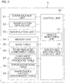
- FIG. 3 is a block diagram showing an electric structure of the remote monitoring server 4.
- the remote monitoring server 4 has a control unit 30.
- the control unit 30 is connected to, e.g., a communication unit 31, a manipulation display unit 32, a manipulation unit 33, and a memory unit 34.
- the communication unit 31 is a communication interface via which the control unit 30 communicates with the remote monitoring terminal 12 (work vehicle 2) and the portable terminal 3 over the communication network 6.
- the manipulation display unit 32 is made of a touch panel display, for example.
- the manipulation unit 33 includes a keyboard and/or a mouse, for example.
- the memory unit 34 is made of a storage device such as a hard disk and/or a nonvolatile memory.
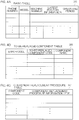
- the memory unit 34 includes, e.g., a basic table 35, a to-be-replaced component table 36, a component replacement procedure table 37, an error monitoring table 38, and a maintenance history management table 39.
- models, machine numbers, latest position information, operating periods, and other operation information (not illustrated) of the work vehicles 2 are stored respectively in association with the phone numbers of the remote monitoring terminals 12 of the work vehicles 2. Every time the remote monitoring server 4 receives position information and operation information from a work vehicle 2, the latest position information and the operating period of the work vehicle 2 are updated by the control unit 30.
- to-be-replaced component table 36 codes (to-be-replaced component codes) and component names of components that should be replaced with new ones for the purpose of eliminating errors indicated by error codes are stored respectively in association with the error codes.
- the to-be-replaced component code is one example of the defective component identification information. If it is necessary to replace two or more components to eliminate an error indicated by a single error code, to-be-replaced component codes and component names of the components are stored in association with the single error code.
- each of the pieces of component replacement procedure information is stored as a portable document format (PDF) file, for example.
- PDF portable document format
- the error monitoring table 38 is a table in which information such as an error code is stored at the time when the remote monitoring server 4 receives error detection information from a work vehicle 2. Specifically, when the control unit 30 receives the error detection information from a work vehicle 2, the control unit 30 stores, in the error monitoring table 38, the phone number of the work vehicle 2, the date and time of error occurrence, and error information including an error code and/or the like, as illustrated in FIG. 5A .
- the maintenance history management table 39 is a table used to manage maintenance history information. As illustrated in FIG. 5B , the maintenance history information includes the phone number of a work vehicle 2 having been subjected to maintenance, the date and time when the maintenance was performed (the date and time of the maintenance), and the content of the maintenance, for example.
- the maintenance history information is inputted by, e.g., an operator after the maintenance is completed, for example.
- the control unit 30 includes a microcomputer having a CPU and a memory (e.g., a ROM, a RAM).
- the control unit 30 includes a remote monitoring unit 41 and a server-side identification control unit 42.
- the remote monitoring unit 41 receives operation information from a work vehicle 2
- the remote monitoring unit 41 updates the operation information included in the basic table 35, or adds the operation information into the basic table 35.
- the remote monitoring unit 41 receives error detection information from a work vehicle 2
- the remote monitoring unit 41 stores the error information in the error monitoring table 38, and notifies the serviceman of the content of the error directly or via the operator.
- the remote monitoring unit 41 when the remote monitoring unit 41 receives the error detection information, the remote monitoring unit 41 displays a warning indicating that the error detection information has been received, and/or outputs a warning sound to notify the operator that the error detection information has been received. When the operator recognizes that the error detection information has been received, the operator notifies the serviceman of the error information. Alternatively, when the remote monitoring unit 41 receives the error detection information, the remote monitoring unit 41 may create an error notifying mail including the error information and transmit the error notifying mail to a serviceman who has been designated in advance.
- the server-side identification control unit 42 performs a server-side identification control process of identifying a work vehicle (identification target) whose image has been captured by the portable terminal 3 and transmitting individual information of the identified work vehicle to the portable terminal 3.
- the server-side identification control process will be described in detail later.
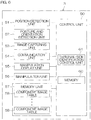
- FIG. 6 is a block diagram showing an electric structure of the portable terminal 3.
- the portable terminal 3 includes a control unit 50.
- the control unit 50 is connected to, e.g., a position detection unit 51, a posture and orientation detection unit 52, an image capturing unit 53, a communication unit 54, a manipulation display unit 55, a manipulation unit 56, and a memory unit 57.
- the position detection unit 51 is configured to calculate position information of the portable terminal 3 through the satellite positioning system.
- the satellite positioning system is GNSS.
- the position detection unit 51 receives satellite signals from the plurality of positioning satellites 7 (see FIG. 1 ), and calculates the position information of the portable terminal 3.
- the position information includes information indicative of a latitude, a longitude, and an altitude, for example.
- the posture and orientation detection unit 52 is configured to detect the posture and orientation of the portable terminal 3.
- the posture of the portable terminal 3 refers to an inclination angle of the portable terminal 3 in three dimensional directions.
- the orientation of the portable terminal 3 refers to an image capturing direction of the image capturing unit 53.
- the posture and orientation detection unit 52 detects the posture and orientation of the portable terminal 3 with, e.g., a gyro sensor, an acceleration sensor, and/or a magnetic field sensor.
- terminal position information refers to information including, of the piece of information indicating the position detected by the position detection unit 51 and the pieces of information indicating the posture and orientation detected by the posture and orientation detection unit 52, at least the piece of information indicating the position.
- the terminal position information includes all of the pieces of information indicating the position, the posture, and the orientation.
- the image capturing unit 53 captures an image of the work vehicle 2 that is the identification target, e.g., with an image capturing device such as CCD or complementary metal oxide semiconductor (CMOS).
- an image capturing device such as CCD or complementary metal oxide semiconductor (CMOS).
- the communication unit 54 is a communication interface via which the control unit 50 communicates with the remote monitoring server 4 over the communication network 6.
- the manipulation display unit 55 is made of a touch panel display, for example.
- the manipulation unit 56 includes one or more manipulation buttons, for example.
- the memory unit 57 is made of a storage device such as a nonvolatile memory.
- the memory unit 57 includes component image tables 58 respectively prepared for the work vehicles 2 of various models. As illustrated in FIG. 7 , in each of the component image tables 58, pieces of information (component position information) indicating the positions of components included in a work vehicle 2 of a corresponding model and images (component images) of the components are stored respectively in association with component codes of the components.
- each of the component images is a three-dimensional computer graphics (CG) image.
- CG computer graphics
- Each of the component images may alternatively be a photographic image or a two-dimensional CG image.
- the component image is displayed in such a manner that the component image is superimposed on the captured image, for example.
- the component position information is information indicating the position of the component relative to the position of the model information on the lateral side of the work vehicle 2.
- the component position information can be xyz coordinate values in the xyz coordinate system whose origin resides at the position of the model information 9 on the lateral side of the work vehicle 2 when observed from the outside of the work vehicle 2.
- the x-axis direction may be a front-rear direction (a direction extending laterally from the lateral side) of the vehicle
- the y-axis direction may be a height direction (a direction extending along the height of the lateral side) of the vehicle
- the z-axis direction may be a left-right direction (a direction extending along the depth of the lateral side) of the vehicle.
- a reference display size of a component image stored in the component image table 58 is set equal to the product of an actual component size multiplied by a predetermined factor.
- coordinate values that are the component position information are also set equal to the products of the actual coordinate values of the work vehicle 2 multiplied by a predetermined factor, for example.
- an absolute value of component position information (coordinate values) and a reference display size of a component image are set equal to values scaled based on the reference work vehicle.
- the size of the work vehicle 2 in the image captured by the image capturing unit 53 changes according to an image capturing condition, such as a distance between the portable terminal 3 and the work vehicle 2 and a zoom magnification.
- an image capturing condition such as a distance between the portable terminal 3 and the work vehicle 2 and a zoom magnification.
- the absolute value of the component position information and the display size of the component image can be changed in the following manner, for example.
- a ratio of the size of the work vehicle in the image with respect to the size of the reference work vehicle is calculated. Based on the ratio thus calculated, the absolute value of the component position information and the display size of the component image are scaled based on the size of the work vehicle in the image.
- the control unit 50 includes a microcomputer having a CPU and a memory (e.g., a ROM, a RAM, a nonvolatile memory) 60.
- a memory e.g., a ROM, a RAM, a nonvolatile memory
- the vehicle identification/information adding program described above is stored in the memory (specifically, a nonvolatile memory) 60.
- the control unit 50 includes a terminal-side identification control unit 61. When the vehicle identification/information adding program is started, the terminal-side identification control unit 61 executes a terminal-side identification control process according to the vehicle identification/information adding program.
- FIG. 8 is a flowchart showing an example of the procedures for the terminal-side identification control process executed by the terminal-side identification control unit 61.
- FIG. 9 is a flowchart showing an example of the procedures for the server-side identification control process executed by the server-side identification control unit 42.
- the terminal-side identification control process shown in FIG. 8 is started when the serviceman arrives at a place where a work vehicle having an error (error vehicle) resides and manipulates the portable terminal 3 to start the vehicle identification/information adding program.
- error vehicle error vehicle
- the terminal-side identification control unit 61 activates the image capturing unit 53 (step S1). Consequently, an image is captured by the image capturing unit 53, and the captured image is displayed on the manipulation display unit 55 via the control unit 50. The captured image is inputted to the terminal-side identification control unit 61.
- the serviceman directs the portable terminal 3 toward the error vehicle so that an image of the lateral side of the error vehicle on which the model information 9 is exhibited can be captured.
- the terminal-side identification control unit 61 executes a model information extraction process for extracting model information from the input image (step S2).
- the model information extraction process can be performed by a known image recognition technique.
- the terminal-side identification control unit 61 transmits, to the remote monitoring server 4, identification and judgment information including the extracted model information and the terminal position information (step S3).
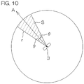
- the server-side identification control unit 42 determines a search area based on the terminal position information included in the identification and judgment information (step S12). Specifically, in a plan view as illustrated in FIG. 10 , the server-side identification control unit 42 determines, as the search area, a fan-shaped area (a hatched area) S having a radius r and extending from the portable terminal 3 along the image capturing direction of the image capturing unit 53 (i.e., extending in the direction A indicated by the arrow in FIG. 10 ).
- An angle made by two radius lines of the fan-shaped area S is a center angle of the fan-shaped area S.
- the center angle of the fan-shaped area S is obtained in the following manner. That is, an angle ⁇ made by one of the radius lines of the fan-shaped area S and the image capturing direction A is added to an angle ⁇ made by the other of the radius lines of the fan-shaped area S and the image capturing direction A. The sum of these angles ⁇ is multiplied by 2 ⁇ . The resulting product corresponds to the center angle of the fan-shaped area S.
- the radius r is set at 30 m
- ⁇ is set at 15 degrees. Namely, in this embodiment, the center angle of the fan-shaped area S is set at 30 degrees.
- the server-side identification control unit 42 searches for a work vehicle 2 satisfying a condition of existing within the search area S and being labeled with the model identical to that indicated by the model information included in the identification and judgment information (step S13).
- the server-side identification control unit 42 After a predetermined period of search time, the server-side identification control unit 42 yields a determination that only one work vehicle 2 satisfying the condition has been found, two or more work vehicles 2 satisfying the condition have been found, or no work vehicle 2 satisfying the condition has been found (step S14).
- the server-side identification control unit 42 transmits, to the portable terminal 3, identification result information including an identification failure notification indicating that the error vehicle whose image has been captured by the portable terminal 3 could not be identified (step S15).
- step S14 If only one work vehicle 2 satisfying the condition has been found in step S14, the server-side identification control unit 42 identifies the work vehicle 2 as the error vehicle (identification target) whose image has been captured by the portable terminal 3 (step S16). Then, the server-side identification control unit 42 advances to step S18.
- step S14 If two or more work vehicles 2 satisfying the condition have been found in step S14, the server-side identification control unit 42 identifies, as the error vehicle (identification target) whose image has been captured by the portable terminal 3, one of the work vehicles 2 located closer to the portable terminal 3 than any other work vehicles 2 (step S17). Then, the server-side identification control unit 42 advances to step S18.
- step S18 based on the tables 35 to 38, the server-side identification control unit 42 obtains individual information of the work vehicle 2 having been identified as the error vehicle (identification target), and transmits, to the portable terminal 3, identification result information including the obtained individual information and an identification success notification.
- the server-side identification control unit 42 obtains, from the basic table 35 illustrated in FIG. 4A , information such as the model, machine number, and/or operating period of the work vehicle 2 having been identified as the error vehicle.
- the server-side identification control unit 42 also obtains, from the error monitoring table 38 illustrated in FIG. 5A , an error code indicating the cause of an error currently occurring in the work vehicle 2 having been identified as the error vehicle.
- the server-side identification control unit 42 obtains, from the to-be-replaced component table 36 illustrated in FIG. 4B , a to-be-replaced component code(s) and a component name(s) associated with the error code obtained from the error monitoring table 38.
- the server-side identification control unit 42 obtains, from the component replacement procedure table 37 illustrated in FIG. 4C , component replacement procedure information associated with the to-be-replaced component code(s) obtained from the to-be-replaced component table 36. Then, the server-side identification control unit 42 transmits, to the portable terminal 3, identification result information including the individual information obtained from the tables 35 to 38 (the model, the machine number, the operating period, the error code, the to-be-replaced component code(s) and the component name(s), the component replacement procedure information, and/or the like) and the identification success notification.
- the terminal-side identification control unit 61 in the portable terminal 3 receives the identification result information from the remote monitoring server 4 (YES in step S4), the terminal-side identification control unit 61 determines whether or not the notification included in the identification result information is an identification success notification (step S5). If the notification included in the identification result information is an identification failure notification (NO in step S5), the terminal-side identification control unit 61 returns to step S2.
- the terminal-side identification control unit 61 executes an information adding process (step S6). Specifically, as illustrated in FIG. 11 , the terminal-side identification control unit 61 displays the model, machine number, operating period included in the identification result information in such a manner that these pieces of information are superimposed on the captured image. As illustrated in FIG. 11 , the terminal-side identification control unit 61 also displays the error code and to-be-replaced component name(s) included in the identification result information and a replacement procedure button 71 in such a manner that the error code, the to-be-replaced component name(s), and the replacement procedure button 71 are superimposed on the captured image.
- the to-be-replaced component name is an MH sensor.
- a to-be-replaced component code may be displayed. If the serviceman presses the replacement procedure button 71, the component replacement procedure information included in the identification result information is displayed.
- the terminal-side identification control unit 61 obtains, from the component image table associated with the model, component position information and a component image corresponding to the to-be-replaced component code. Next, as described above, the terminal-side identification control unit 61 adjusts the absolute value of the component position information and the display size of the component image based on the size indicated by the model information 9 extracted from the captured image. Then, as indicated by the component image 72 within the broken line in FIG.
- the terminal-side identification control unit 61 displays the component image in such a manner that the component image is superimposed on the captured image at a location indicated by the adjusted component position information and at the adjusted display size.
- an enlarged image of a small area including the model information 9 of the work vehicle 2 may be displayed at a predetermined area (e.g., at a corner) in the image, for the purpose of notifying a user of the location based on which the identification and determination are performed.
- the terminal-side identification control unit 61 determines whether or not the serviceman has performed a manipulation for retrying the identification of the error vehicle (step S7).
- the terminal-side identification control unit 61 may display, on its display screen, an identification retry button, for example. If the identification retry button is manipulated by the serviceman, the terminal-side identification control unit 61 may determine that the manipulation for retrying the identification of the error vehicle has been performed.
- the terminal-side identification control unit 61 determines whether or not the serviceman has performed a manipulation for ending the vehicle identification/information adding program (step S8). If the manipulation for ending the vehicle identification/information adding program has not been performed (NO in step S8), the terminal-side identification control unit 61 returns to step S7.
- step S7 If it is determined in step S7 that the manipulation for retrying the identification of the error vehicle has been performed (YES in step S7), the terminal-side identification control unit 61 returns to step S2. Accordingly, the processes of step S2 and the subsequent steps will be executed again.
- step S8 If it is determined in step S8 that the manipulation for ending the vehicle identification/information adding program has been performed (YES in step S8), the terminal-side identification control unit 61 ends the terminal-side identification control process.
- an image of a work vehicle 2 that is an identification target is captured by the portable terminal 3, and model information of the identification target is extracted therefrom. Then, identification and judgment information including the model information of the identification target and the terminal position information of the portable terminal 3 is transmitted to the remote monitoring server 4.
- the remote monitoring server 4 determines a search area S based on the terminal position information, and searches for a work vehicle 2 satisfying a condition of existing within the determined search area S and being labeled with the model identical to that indicated by the model information of the identification target. If a work vehicle 2 satisfying the condition has been found, the work vehicle 2 is identified as the identification target. Consequently, even in a case where there exists a plurality of work vehicles 2 including two or more work vehicles 2 having the identical model information, it is possible to identify an identification target at an individual level by capturing an image of the identification target with the portable terminal 3.
- the user in the example in the embodiment described above, the serviceman of the portable terminal 3 can recognize the individual information of the identification target, such as the model, the machine number, the operating period, the error code, the to-be-replaced component name, and/or the component replacement procedure information of the identification target.
- the portable terminal 3 it is possible to display the component image corresponding to the to-be-replaced component code included in the individual information in such a manner that the component image is superimposed on a corresponding portion of the image captured by the portable terminal 3. Consequently, the user (in the example in the embodiment described above, the serviceman) of the portable terminal 3 can visually recognize the defective portion.
- the portable terminal 3 may display information related to the maintenance in such a manner that the information is superimposed on the captured image, as illustrated in FIG. 12 .
- the MH sensor (the component image 72) is not defective, but is an object that is recommended to be replaced.
- the following messages are superimposed on the captured image and displayed: "One hundred hours have passed since the last replacement. Replacement is recommended.” and "The last oil change was on June 12, 2016."
- such messages can be created by the remote monitoring server 4 based on the maintenance history management table 39 (see FIG. 5B ), and can be incorporated into the identification result information as individual information. Then, these messages can be transmitted to the portable terminal 3.
- the replacement recommended component is treated in a similar manner to the to-be-replaced component described above.
- the error code, the to-be-replaced component name, and the replacement procedure button 71 are displayed therefor in a similar manner to those in FIG. 11 .
- the remote monitoring server 4 may create, as individual information, a maintenance recommendation message or the like based on an estimation performed with various detection values from the identification target 2, and incorporates the maintenance recommendation message or the like into the individual information. Consequently, the maintenance recommendation message can be displayed on the portable terminal 3.
- the maintenance recommendation message can be as below: "The value of the loss sensor is high. Inspection of the loss sensor is recommended.”
- the portable terminal 3 transmits, to the remote monitoring server 4, the terminal position information including the pieces of information indicating the position, posture, and orientation as well as the identification and judgment information including the model information.
- the terminal position information only needs to include the position information. For example, if the terminal position information includes the information indicating the position but does not include the information indicating the posture and orientation, the remote monitoring server 4 determines a search area S shaped in a circular area that is centered on the portable terminal 3 and that has a predetermined radius in a plan view.
- the positioning system employed by each of the remote monitoring terminal 12 of the work vehicle 2 and the portable terminal 3 is GNSS, which is a point positioning system.
- the remote monitoring terminal 12 and the portable terminal 3 may employ a positioning system that is not the point positioning system, such as real time kinematic-GNSS (RTK-GNSS).
- RTK-GNSS real time kinematic-GNSS
- the work vehicle that is the identification target may be a tractor, a rice transplanter, a civil engineering and construction work machine, a snowplow, a riding-type working machine, a walking-type work machine, or the like.
- the identification object may be an object that is not the work vehicle.
Landscapes
- Engineering & Computer Science (AREA)
- General Physics & Mathematics (AREA)
- Theoretical Computer Science (AREA)
- Physics & Mathematics (AREA)
- Multimedia (AREA)
- Business, Economics & Management (AREA)
- Human Resources & Organizations (AREA)
- Computer Vision & Pattern Recognition (AREA)
- Entrepreneurship & Innovation (AREA)
- Economics (AREA)
- Marketing (AREA)
- Operations Research (AREA)
- Quality & Reliability (AREA)
- Strategic Management (AREA)
- Tourism & Hospitality (AREA)
- General Business, Economics & Management (AREA)
- Signal Processing (AREA)
- Management, Administration, Business Operations System, And Electronic Commerce (AREA)
- Image Processing (AREA)
- Image Analysis (AREA)
- Processing Or Creating Images (AREA)
Abstract
Description
- The present invention relates to an object identification system.
- Patent Literature 1 (hereinafter, referred to as PTL 1) discloses an object identification system including a terminal device with a camera and a server communicable with the terminal device. Specifically, the terminal device transmits an image (input image) captured by the camera to the server. The server extracts a feature quantity from the image received from the terminal device, and compares the extracted feature quantity with a first feature quantity dictionary to identify an object in the received image. Thereafter, in accordance with the result of the identification, the server obtains a second feature quantity dictionary and additional information that are to be supplied to the terminal device. Then, the server transmits the second feature quantity dictionary and the additional information to the terminal device. The quantity of data included in the second feature quantity dictionary is smaller than that of the first feature quantity dictionary.
- The terminal device extracts a feature quantity from an input image, and compares the extracted feature quantity with the second feature quantity dictionary obtained from the server. In this manner, the terminal device identifies an object in the input image. Next, the terminal device obtains additional information related to the identified object from an additional information database obtained from the server, and superimposes the obtained additional information on the input image, so as to generate an output image. Then, the terminal device displays the output image on a display unit.
- PTL 1: Japanese Patent Application Laid-Open No.
2015-212967 - According to the object identification system of
PTL 1, the terminal device compares a feature quantity of an input image with the second feature quantity dictionary obtained from the server to identify an object in the input image. However, if there exists a plurality of vehicles of the same model, e.g., a plurality of work vehicles, it is difficult to identify a work vehicle at an individual level based on a feature quantity of the work vehicle in an input image. - The present invention has an object to provide an object identification system capable of identifying an identification target at an individual level by capturing an image of the identification target with a terminal device, even in a case where there exists a plurality of identification objects including two or more identification objects having the identical feature information.
- An object identification system of the present invention includes:
- a terminal device capable of capturing an image of an identification target that is an identification object to be identified from among identification objects respectively having pieces of feature information whose images are capturable externally; and
- a server communicable with the terminal device, wherein
- the terminal device includes
- a detecting unit configured to detect terminal position information including information indicating a position and an orientation of the terminal device,
- an image capturing unit configured to capture an image of the identification target, and
- a terminal-side identification control unit configured to extract feature information of the identification target from the image captured by the image capturing unit, and to transmit, to the server, identification and judgment information including the feature information thus extracted and the terminal position information, and
- the server includes
- a memory unit in which pieces of feature information and pieces of position information of the identification objects are stored respectively in association with the identification objects, and
- a server-side identification control unit configured to determine a search area based on the terminal position information included in the identification and judgment information received from the terminal device, to search for a predetermined identification object satisfying a condition of existing within the search area thus determined and having feature information identical to the feature information included in the identification and judgment information, and to identify, when a predetermined identification satisfying the condition is found as a result of the search, the predetermined identification as the identification target.
- The identification object refers to an object that can be a target to be identified by the object identification system of the present invention. The identification target refers to, among the identification objects, a target to be identified distinctively from the others.
- With this configuration, an image of an identification target is captured by the image capturing unit of the terminal device, and feature information of the identification target is extracted therefrom. Then, identification and judgment information including the feature information of the identification target and the terminal position information is transmitted to the server. The server determines a search area based on the terminal position information, and searches for an identification object satisfying a condition of existing within the search area thus determined and having feature information identical to the feature information included in the identification and judgment information (i.e., the feature information of the identification target). If the identification object satisfying the condition is found, the identification object is identified as the identification target. Thus, even in a case where there exist identification objects including two or more identification objects having the identical feature information, it is possible to identify an identification target at an individual level by capturing an image of the identification target with the terminal device.
- According to an embodiment of the present invention, in a case where there exist two or more predetermined identification objects satisfying the condition, the server-side identification control unit identifies, as the identification target, one of the predetermined identification objects located closer to the terminal device than any other predetermined identification objects.
- With this configuration, even in a case where the captured image includes a plurality of identification objects having feature information identical to the feature information of the identification target, it is possible to identify the identification target.
- According to an embodiment of the present invention, in the memory unit, pieces of feature information, pieces of position information, and pieces of individual information of the identification objects are stored respectively in association with the identification objects, and in a case where the server-side identification control unit identifies the predetermined identification object as the identification target, the server-side identification control unit transmits, to the terminal device, a piece of individual information associated with the predetermined identification object from among the pieces of individual information stored in the memory unit.
- With this configuration, the server can transmit, to the terminal device, the individual information of the identification object having been identified as the identification target.
- According to an embodiment of the present invention, the terminal device further includes a display unit configured to display thereon the image captured by the image capturing unit, and the terminal-side identification control unit displays the piece of individual information from the server-side identification control unit in such a manner that the piece of individual information is superimposed on the image displayed on the display unit.
- With this configuration, a user of the terminal device can recognize the individual information of the identification target.
- According to an embodiment of the present invention, each of the pieces of individual information includes at least one of a piece of identification information used to identify a corresponding one of the identification objects, a piece of operation information of the corresponding one of the identification objects, and a piece of maintenance information of the corresponding one of the identification objects.
- With this configuration, the user of the terminal device can recognize at least one of the identification information, the operation information, and the maintenance information of the identification target.
- According to an embodiment of the present invention, each of the pieces of individual information includes a piece of defective component identification information indicating a defective component of a corresponding one of the identification objects, and, based on a piece of defective component identification information included in the piece of individual information from the server-side identification control unit, the terminal-side identification control unit displays an image of a defective component corresponding to the piece of defective component identification information in such a manner that the image of the defective component is superimposed on the image displayed on the display unit.
- With this configuration, the user of the terminal device can visually recognize a defective portion.
- According to an embodiment of the present invention, the feature information is model information of a corresponding one of the identification objects.
- The above and other objects, features, and effects of the present invention will be apparent from the following descriptions of the embodiments and the accompanying drawings.
- [
FIG. 1] FIG. 1 is a view schematically illustrating a configuration of a work vehicle identification system including an object identification system according to an embodiment of the present invention. - [
FIG. 2] FIG. 2 is a block diagram showing a main electric structure of a work vehicle. - [
FIG. 3] FIG. 3 is a block diagram showing an electric structure of a remote monitoring server. - [
FIG. 4A] FIG. 4A is a schematic view of an example of the content of a basic table. - [
FIG. 4B] FIG. 4B is a schematic view of an example of the content of a to-be-replaced component table. - [
FIG. 4C] FIG. 4C is a schematic view of an example of the content of a component replacement procedure table. - [
FIG. 5A] FIG. 5A is a schematic view of an example of the content of an error monitoring table. - [
FIG. 5B] FIG. 5B is a schematic view of an example of the content of a maintenance history management table. - [
FIG. 6] FIG. 6 is a block diagram showing an electric structure of a portable terminal. - [
FIG. 7] FIG. 7 is a schematic view of an example of the content of a component image table. - [
FIG. 8] FIG. 8 is a flowchart showing an example of procedures for a terminal-side identification control process executed by a terminal-side identification control unit. - [
FIG. 9] FIG. 9 is a flowchart showing an example of procedures for a server-side identification control process executed by a server-side identification control unit. - [
FIG. 10] FIG. 10 is a schematic view for explaining a method for determining a search area. - [
FIG. 11] FIG. 11 is a schematic view illustrating an example of individual information and a component image superimposed on a captured image. - [
FIG. 12] FIG. 12 is a schematic view illustrating another example of individual information and a component image superimposed on a captured image. -
FIG. 1 is a view schematically illustrating a configuration of a work vehicle identification system including an object identification system according to an embodiment of the present invention. - A work
vehicle identification system 1 is a system for identifying, at an individual level, awork vehicle 2 that is an identification object. The workvehicle identification system 1 includes a portable terminal device (hereinafter, referred to as a "terminal device 3") and aremote monitoring server 4. - The
work vehicle 2 is communicable with theremote monitoring server 4 over a communication network 6. Thework vehicle 2 has a function to measure its own position via apositioning satellite 7. Thework vehicle 2 has a lateral side on whichmodel information 9 indicating the model of thework vehicle 2 is exhibited. Themodel information 9 of thework vehicle 2 illustrated inFIG. 1 is "YH448". Themodel information 9 is one example of the feature information of the identification object. - The
portable terminal 3 is a portable terminal such as a smartphone or a tablet-type personal computer (tablet PC). In the present embodiment, theportable terminal 3 is a smartphone. Theportable terminal 3 includes an image capturing unit 53 (seeFIG. 6 ), such as a charge-coupled device (CCD) camera. Theportable terminal 3 has a function to measure its own position via thepositioning satellite 7. Theportable terminal 3 has a vehicle identification/information adding program developed to implement the present embodiment. The vehicle identification/information adding program is an application program for identifying thework vehicle 2 in cooperation with theremote monitoring server 4 and adding information to a captured image through AR. Here, AR is a technique called "augmented reality", and is used to extend the real world by displaying additional information on the real world. Theportable terminal 3 is communicable with theremote monitoring server 4 over the communication network 6. In this embodiment, when maintenance is conducted, theportable terminal 3 is carried by, e.g., a serviceman who is in charge of the maintenance of thework vehicle 2. - The
remote monitoring server 4 is a server provided in a remote monitoring center 5 and configured to remotely monitor a plurality ofwork vehicles 2. Theremote monitoring server 4 is communicable with thework vehicles 2 and theportable terminal 3 over the communication network 6. - The following will describe an outline of entire operation of the work
vehicle identification system 1. - The
work vehicle 2 transmits, to theremote monitoring server 4, information such as identification information, position information, operation information, and/or error detection information (abnormality information) of thework vehicle 2. In this embodiment, the identification information of thework vehicle 2 transmitted from thework vehicle 2 to theremote monitoring server 4 is a phone number of a remote monitoring terminal 12 (seeFIG. 2 ) provided in thework vehicle 2, as will be described later. The identification information may alternatively be a machine number that is identification information uniquely allocated to thework vehicle 2. - Upon reception of the information such as the identification information, the position information, the operation information, and/or the error detection information from one of the
work vehicles 2, theremote monitoring server 4 stores these pieces of information therein in association with the identification information, the model information, and the machine number of the one of thework vehicles 2. In a case where theremote monitoring server 4 has received the error detection information from thework vehicle 2, theremote monitoring server 4 notifies the serviceman of the error directly or via an operator. The serviceman who carries theportable terminal 3 goes to a place where thework vehicle 2 having the error resides. In the following description, thework vehicle 2 having the error may be referred to as an "error vehicle" occasionally. - When the serviceman arrives at the place where the error vehicle resides, the serviceman operates the
portable terminal 3 to start the vehicle identification/information adding program. When the vehicle identification/information adding program is started, theimage capturing unit 53 is activated. Then, the serviceman sets an image capturing direction of theportable terminal 3 toward the lateral side of the error vehicle (identification target). More specifically, the serviceman directs theportable terminal 3 toward the error vehicle to capture an image of the lateral side of the error vehicle on which themodel information 9 is exhibited. Consequently, the image including the error vehicle is ready to be inputted from theimage capturing unit 53 to theportable terminal 3. - The
portable terminal 3 extracts themodel information 9 from the input image. Then, theportable terminal 3 transmits, to theremote monitoring server 4, identification and judgment information including the extractedmodel information 9 and the position information of the portable terminal 3 (which may include the information indicating the posture and orientation of the portable terminal 3). - Upon reception of the identification and judgment information from the
portable terminal 3, theremote monitoring server 4 determines a search area at a location close to theportable terminal 3, based on the position information included in the identification and judgment information. Next, based on the pieces of latest position information of the plurality ofwork vehicles 2, theremote monitoring server 4 searches for awork vehicle 2 satisfying a condition of existing within the search area and being labeled with the model identical to that indicated by themodel information 9 included in the identification and judgment information. If theremote monitoring server 4 finds awork vehicle 2 satisfying the condition, theremote monitoring server 4 identifies thework vehicle 2 as the error vehicle (identification target), and transmits information (hereinafter, referred to as "individual information") about thework vehicle 2 to theportable terminal 3. Upon reception of the individual information, theportable terminal 3 displays predetermined information included in the individual information in such a manner that the predetermined information is superimposed on the input image, or displays an image (e.g., a component image) corresponding to the predetermined information included in the individual information in such a manner that the image is superimposed on the input image. - The following will describe electric structures of the
work vehicle 2, theremote monitoring server 4, and theportable terminal 3. -
FIG. 2 is a block diagram showing a main electric structure of thework vehicle 2. - The
work vehicle 2 includes a workvehicle control device 11 and aremote monitoring terminal 12. The workvehicle control device 11 controls electric components in various parts of thework vehicle 2. In a case where thework vehicle 2 is a combine harvester, for example, the workvehicle control device 11 controls electric components in various parts of the combine harvester, such as a traveling device, a reaping device, a carrying device, and a threshing device. The workvehicle control device 11 provides theremote monitoring terminal 12 with information such as the operation information and the error detection information of thework vehicle 2. Examples of the operation information encompass an operating period, an engine speed, an exhaust gas temperature, a manipulation state of an accelerator, and a manipulation state of a brake. In this embodiment, the error detection information includes an error code indicating a type of an error. - The
remote monitoring terminal 12 transmits, to theremote monitoring server 4, information such as the position information of thework vehicle 2 as well as the operation information and the error detection information supplied from the workvehicle control device 11. In this embodiment, theremote monitoring terminal 12 has a phone number for communication. - The
remote monitoring terminal 12 has acontrol unit 20. Thecontrol unit 20 is connected to, e.g., aposition detection unit 21, acommunication unit 22, amanipulation display unit 23, amanipulation unit 24, and amemory unit 25. Theposition detection unit 21 is configured to calculate position information of theremote monitoring terminal 12 through a satellite positioning system. In this embodiment, the satellite positioning system is global navigation satellite system (GNSS). Specifically, theposition detection unit 21 receives satellite signals from the plurality of positioning satellites 7 (seeFIG. 1 ), and calculates the position information of the remote monitoring terminal 12 (work vehicle 2). The position information includes information indicative of a latitude, a longitude, and an altitude, for example. - The
communication unit 22 is a communication interface via which thecontrol unit 20 communicates with theremote monitoring server 4 over the communication network 6. Themanipulation display unit 23 is made of a touch panel display, for example. Themanipulation unit 24 includes one or more manipulation buttons, for example. Thememory unit 25 is made of a storage device such as a nonvolatile memory. - The
control unit 20 includes a microcomputer having a central processing unit (CPU) and a memory (e.g., a ROM, a RAM). Thecontrol unit 20 obtains, at every predetermined period, the position information calculated by theposition detection unit 21, and stores the position information in thememory unit 25. Then, thecontrol unit 20 transmits, at every predetermined period, the latest position information stored in thememory unit 25 to theremote monitoring server 4. - The
control unit 20 accumulates, in thememory unit 25, the operation information supplied from the workvehicle control device 11. Then, at a predetermined timing (e.g., at a timing when a manipulation for turning off the power is performed), thecontrol unit 20 transmits the operation information accumulated in thememory unit 25 to theremote monitoring server 4 in a batch. When thecontrol unit 20 receives the error detection information from the workvehicle control device 11, thecontrol unit 20 stores the error detection information in thememory unit 25, and transmits the error detection information to theremote monitoring server 4. -
FIG. 3 is a block diagram showing an electric structure of theremote monitoring server 4. - The
remote monitoring server 4 has acontrol unit 30. Thecontrol unit 30 is connected to, e.g., acommunication unit 31, amanipulation display unit 32, amanipulation unit 33, and amemory unit 34. Thecommunication unit 31 is a communication interface via which thecontrol unit 30 communicates with the remote monitoring terminal 12 (work vehicle 2) and theportable terminal 3 over the communication network 6. Themanipulation display unit 32 is made of a touch panel display, for example. Themanipulation unit 33 includes a keyboard and/or a mouse, for example. Thememory unit 34 is made of a storage device such as a hard disk and/or a nonvolatile memory. - The
memory unit 34 includes, e.g., a basic table 35, a to-be-replaced component table 36, a component replacement procedure table 37, an error monitoring table 38, and a maintenance history management table 39. - As illustrated in
FIG. 4A , in the basic table 35, models, machine numbers, latest position information, operating periods, and other operation information (not illustrated) of thework vehicles 2 are stored respectively in association with the phone numbers of theremote monitoring terminals 12 of thework vehicles 2. Every time theremote monitoring server 4 receives position information and operation information from awork vehicle 2, the latest position information and the operating period of thework vehicle 2 are updated by thecontrol unit 30. - As illustrated in
FIG. 4B , in the to-be-replaced component table 36, codes (to-be-replaced component codes) and component names of components that should be replaced with new ones for the purpose of eliminating errors indicated by error codes are stored respectively in association with the error codes. The to-be-replaced component code is one example of the defective component identification information. If it is necessary to replace two or more components to eliminate an error indicated by a single error code, to-be-replaced component codes and component names of the components are stored in association with the single error code. - As illustrated in
FIG. 4C , in the component replacement procedure table 37, pieces of information indicating procedures for replacing components are stored respectively in association with component codes (to-be-replaced component codes). Each of the pieces of component replacement procedure information is stored as a portable document format (PDF) file, for example. - The error monitoring table 38 is a table in which information such as an error code is stored at the time when the
remote monitoring server 4 receives error detection information from awork vehicle 2. Specifically, when thecontrol unit 30 receives the error detection information from awork vehicle 2, thecontrol unit 30 stores, in the error monitoring table 38, the phone number of thework vehicle 2, the date and time of error occurrence, and error information including an error code and/or the like, as illustrated inFIG. 5A . - The maintenance history management table 39 is a table used to manage maintenance history information. As illustrated in
FIG. 5B , the maintenance history information includes the phone number of awork vehicle 2 having been subjected to maintenance, the date and time when the maintenance was performed (the date and time of the maintenance), and the content of the maintenance, for example. The maintenance history information is inputted by, e.g., an operator after the maintenance is completed, for example. - Referring back to
FIG. 3 , thecontrol unit 30 includes a microcomputer having a CPU and a memory (e.g., a ROM, a RAM). Thecontrol unit 30 includes aremote monitoring unit 41 and a server-sideidentification control unit 42. When theremote monitoring unit 41 receives operation information from awork vehicle 2, theremote monitoring unit 41 updates the operation information included in the basic table 35, or adds the operation information into the basic table 35. When theremote monitoring unit 41 receives error detection information from awork vehicle 2, theremote monitoring unit 41 stores the error information in the error monitoring table 38, and notifies the serviceman of the content of the error directly or via the operator. - For example, when the
remote monitoring unit 41 receives the error detection information, theremote monitoring unit 41 displays a warning indicating that the error detection information has been received, and/or outputs a warning sound to notify the operator that the error detection information has been received. When the operator recognizes that the error detection information has been received, the operator notifies the serviceman of the error information. Alternatively, when theremote monitoring unit 41 receives the error detection information, theremote monitoring unit 41 may create an error notifying mail including the error information and transmit the error notifying mail to a serviceman who has been designated in advance. - The server-side
identification control unit 42 performs a server-side identification control process of identifying a work vehicle (identification target) whose image has been captured by theportable terminal 3 and transmitting individual information of the identified work vehicle to theportable terminal 3. The server-side identification control process will be described in detail later. -
FIG. 6 is a block diagram showing an electric structure of theportable terminal 3. - The
portable terminal 3 includes acontrol unit 50. Thecontrol unit 50 is connected to, e.g., aposition detection unit 51, a posture andorientation detection unit 52, animage capturing unit 53, acommunication unit 54, amanipulation display unit 55, amanipulation unit 56, and amemory unit 57. Theposition detection unit 51 is configured to calculate position information of theportable terminal 3 through the satellite positioning system. In this embodiment, the satellite positioning system is GNSS. Specifically, theposition detection unit 51 receives satellite signals from the plurality of positioning satellites 7 (seeFIG. 1 ), and calculates the position information of theportable terminal 3. The position information includes information indicative of a latitude, a longitude, and an altitude, for example. - The posture and
orientation detection unit 52 is configured to detect the posture and orientation of theportable terminal 3. The posture of theportable terminal 3 refers to an inclination angle of theportable terminal 3 in three dimensional directions. The orientation of theportable terminal 3 refers to an image capturing direction of theimage capturing unit 53. The posture andorientation detection unit 52 detects the posture and orientation of theportable terminal 3 with, e.g., a gyro sensor, an acceleration sensor, and/or a magnetic field sensor. - In the following description, terminal position information refers to information including, of the piece of information indicating the position detected by the
position detection unit 51 and the pieces of information indicating the posture and orientation detected by the posture andorientation detection unit 52, at least the piece of information indicating the position. In this embodiment, the terminal position information includes all of the pieces of information indicating the position, the posture, and the orientation. - The
image capturing unit 53 captures an image of thework vehicle 2 that is the identification target, e.g., with an image capturing device such as CCD or complementary metal oxide semiconductor (CMOS). - The
communication unit 54 is a communication interface via which thecontrol unit 50 communicates with theremote monitoring server 4 over the communication network 6. Themanipulation display unit 55 is made of a touch panel display, for example. Themanipulation unit 56 includes one or more manipulation buttons, for example. Thememory unit 57 is made of a storage device such as a nonvolatile memory. - The
memory unit 57 includes component image tables 58 respectively prepared for thework vehicles 2 of various models. As illustrated inFIG. 7 , in each of the component image tables 58, pieces of information (component position information) indicating the positions of components included in awork vehicle 2 of a corresponding model and images (component images) of the components are stored respectively in association with component codes of the components. In this embodiment, each of the component images is a three-dimensional computer graphics (CG) image. Each of the component images may alternatively be a photographic image or a two-dimensional CG image. As will be described later, in order to clearly indicate a to-be-replaced component on the captured image, the component image is displayed in such a manner that the component image is superimposed on the captured image, for example. - The component position information is information indicating the position of the component relative to the position of the model information on the lateral side of the
work vehicle 2. For example, the component position information can be xyz coordinate values in the xyz coordinate system whose origin resides at the position of themodel information 9 on the lateral side of thework vehicle 2 when observed from the outside of thework vehicle 2. In this case, for example, the x-axis direction may be a front-rear direction (a direction extending laterally from the lateral side) of the vehicle, the y-axis direction may be a height direction (a direction extending along the height of the lateral side) of the vehicle, and the z-axis direction may be a left-right direction (a direction extending along the depth of the lateral side) of the vehicle. - A reference display size of a component image stored in the component image table 58 is set equal to the product of an actual component size multiplied by a predetermined factor. Similarly, coordinate values that are the component position information are also set equal to the products of the actual coordinate values of the
work vehicle 2 multiplied by a predetermined factor, for example. In other words, in a case where a work vehicle scaled to a size corresponding to the product of the actual size of the work vehicle multiplied by a predetermined factor is a reference work vehicle, an absolute value of component position information (coordinate values) and a reference display size of a component image are set equal to values scaled based on the reference work vehicle. - The size of the
work vehicle 2 in the image captured by theimage capturing unit 53 changes according to an image capturing condition, such as a distance between theportable terminal 3 and thework vehicle 2 and a zoom magnification. Thus, in order to display a component image in such a manner that the component image is superimposed on a corresponding portion of the work vehicle in the captured image, it is necessary to convert the absolute value of the component position information and the display size of the component image into values scaled based on the size of the work vehicle in the captured image. The absolute value of the component position information and the display size of the component image can be changed in the following manner, for example. That is, with reference to the size indicated by themodel information 9 of the work vehicle in the image, a ratio of the size of the work vehicle in the image with respect to the size of the reference work vehicle is calculated. Based on the ratio thus calculated, the absolute value of the component position information and the display size of the component image are scaled based on the size of the work vehicle in the image. - The
control unit 50 includes a microcomputer having a CPU and a memory (e.g., a ROM, a RAM, a nonvolatile memory) 60. In the memory (specifically, a nonvolatile memory) 60, the vehicle identification/information adding program described above is stored. Thecontrol unit 50 includes a terminal-sideidentification control unit 61. When the vehicle identification/information adding program is started, the terminal-sideidentification control unit 61 executes a terminal-side identification control process according to the vehicle identification/information adding program. -
FIG. 8 is a flowchart showing an example of the procedures for the terminal-side identification control process executed by the terminal-sideidentification control unit 61. -
FIG. 9 is a flowchart showing an example of the procedures for the server-side identification control process executed by the server-sideidentification control unit 42. - For example, the terminal-side identification control process shown in
FIG. 8 is started when the serviceman arrives at a place where a work vehicle having an error (error vehicle) resides and manipulates theportable terminal 3 to start the vehicle identification/information adding program. - When the terminal-side identification control process is started, the terminal-side
identification control unit 61 activates the image capturing unit 53 (step S1). Consequently, an image is captured by theimage capturing unit 53, and the captured image is displayed on themanipulation display unit 55 via thecontrol unit 50. The captured image is inputted to the terminal-sideidentification control unit 61. The serviceman directs theportable terminal 3 toward the error vehicle so that an image of the lateral side of the error vehicle on which themodel information 9 is exhibited can be captured. - The terminal-side
identification control unit 61 executes a model information extraction process for extracting model information from the input image (step S2). The model information extraction process can be performed by a known image recognition technique. - When the model information is extracted from the input image, the terminal-side
identification control unit 61 transmits, to theremote monitoring server 4, identification and judgment information including the extracted model information and the terminal position information (step S3). - As shown in
FIG. 9 , when the server-sideidentification control unit 42 in theremote monitoring server 4 receives the identification and judgment information from the terminal-side identification control unit 61 (YES in step S11), the server-sideidentification control unit 42 determines a search area based on the terminal position information included in the identification and judgment information (step S12). Specifically, in a plan view as illustrated inFIG. 10 , the server-sideidentification control unit 42 determines, as the search area, a fan-shaped area (a hatched area) S having a radius r and extending from theportable terminal 3 along the image capturing direction of the image capturing unit 53 (i.e., extending in the direction A indicated by the arrow inFIG. 10 ). An angle made by two radius lines of the fan-shaped area S is a center angle of the fan-shaped area S. The center angle of the fan-shaped area S is obtained in the following manner. That is, an angle θ made by one of the radius lines of the fan-shaped area S and the image capturing direction A is added to an angle θ made by the other of the radius lines of the fan-shaped area S and the image capturing direction A. The sum of these angles θ is multiplied by 2θ. The resulting product corresponds to the center angle of the fan-shaped area S. In this embodiment, the radius r is set at 30 m, and θ is set at 15 degrees. Namely, in this embodiment, the center angle of the fan-shaped area S is set at 30 degrees. - Next, based on the pieces of latest position information of the plurality of
work vehicles 2 stored in the basic table 35 illustrated inFIG. 4A , the server-sideidentification control unit 42 searches for awork vehicle 2 satisfying a condition of existing within the search area S and being labeled with the model identical to that indicated by the model information included in the identification and judgment information (step S13). - After a predetermined period of search time, the server-side
identification control unit 42 yields a determination that only onework vehicle 2 satisfying the condition has been found, two ormore work vehicles 2 satisfying the condition have been found, or nowork vehicle 2 satisfying the condition has been found (step S14). - If no
work vehicle 2 satisfying the condition has been found, the server-sideidentification control unit 42 transmits, to theportable terminal 3, identification result information including an identification failure notification indicating that the error vehicle whose image has been captured by theportable terminal 3 could not be identified (step S15). - If only one
work vehicle 2 satisfying the condition has been found in step S14, the server-sideidentification control unit 42 identifies thework vehicle 2 as the error vehicle (identification target) whose image has been captured by the portable terminal 3 (step S16). Then, the server-sideidentification control unit 42 advances to step S18. - If two or
more work vehicles 2 satisfying the condition have been found in step S14, the server-sideidentification control unit 42 identifies, as the error vehicle (identification target) whose image has been captured by theportable terminal 3, one of thework vehicles 2 located closer to theportable terminal 3 than any other work vehicles 2 (step S17). Then, the server-sideidentification control unit 42 advances to step S18. - In step S18, based on the tables 35 to 38, the server-side
identification control unit 42 obtains individual information of thework vehicle 2 having been identified as the error vehicle (identification target), and transmits, to theportable terminal 3, identification result information including the obtained individual information and an identification success notification. - Specifically, the server-side
identification control unit 42 obtains, from the basic table 35 illustrated inFIG. 4A , information such as the model, machine number, and/or operating period of thework vehicle 2 having been identified as the error vehicle. The server-sideidentification control unit 42 also obtains, from the error monitoring table 38 illustrated inFIG. 5A , an error code indicating the cause of an error currently occurring in thework vehicle 2 having been identified as the error vehicle. In addition, the server-sideidentification control unit 42 obtains, from the to-be-replaced component table 36 illustrated inFIG. 4B , a to-be-replaced component code(s) and a component name(s) associated with the error code obtained from the error monitoring table 38. Furthermore, the server-sideidentification control unit 42 obtains, from the component replacement procedure table 37 illustrated inFIG. 4C , component replacement procedure information associated with the to-be-replaced component code(s) obtained from the to-be-replaced component table 36. Then, the server-sideidentification control unit 42 transmits, to theportable terminal 3, identification result information including the individual information obtained from the tables 35 to 38 (the model, the machine number, the operating period, the error code, the to-be-replaced component code(s) and the component name(s), the component replacement procedure information, and/or the like) and the identification success notification. - Referring back to
FIG. 8 , when the portable-terminal-sideidentification control unit 61 in theportable terminal 3 receives the identification result information from the remote monitoring server 4 (YES in step S4), the terminal-sideidentification control unit 61 determines whether or not the notification included in the identification result information is an identification success notification (step S5). If the notification included in the identification result information is an identification failure notification (NO in step S5), the terminal-sideidentification control unit 61 returns to step S2. - If the notification included in the identification result information is an identification success notification (YES in step S5), the terminal-side
identification control unit 61 executes an information adding process (step S6). Specifically, as illustrated inFIG. 11 , the terminal-sideidentification control unit 61 displays the model, machine number, operating period included in the identification result information in such a manner that these pieces of information are superimposed on the captured image. As illustrated inFIG. 11 , the terminal-sideidentification control unit 61 also displays the error code and to-be-replaced component name(s) included in the identification result information and areplacement procedure button 71 in such a manner that the error code, the to-be-replaced component name(s), and thereplacement procedure button 71 are superimposed on the captured image. In this example, the to-be-replaced component name is an MH sensor. Instead of or in addition to the to-be-replaced component name, a to-be-replaced component code may be displayed. If the serviceman presses thereplacement procedure button 71, the component replacement procedure information included in the identification result information is displayed. - In addition, based on the model and to-be-replaced component code (in this example, the component name corresponding to the code is the MH sensor) included in the identification result information, the terminal-side
identification control unit 61 obtains, from the component image table associated with the model, component position information and a component image corresponding to the to-be-replaced component code. Next, as described above, the terminal-sideidentification control unit 61 adjusts the absolute value of the component position information and the display size of the component image based on the size indicated by themodel information 9 extracted from the captured image. Then, as indicated by thecomponent image 72 within the broken line inFIG. 11 , the terminal-sideidentification control unit 61 displays the component image in such a manner that the component image is superimposed on the captured image at a location indicated by the adjusted component position information and at the adjusted display size. Although not illustrated inFIG. 11 , an enlarged image of a small area including themodel information 9 of thework vehicle 2 may be displayed at a predetermined area (e.g., at a corner) in the image, for the purpose of notifying a user of the location based on which the identification and determination are performed. - Thereafter, the terminal-side
identification control unit 61 determines whether or not the serviceman has performed a manipulation for retrying the identification of the error vehicle (step S7). Although not illustrated inFIG. 11 , the terminal-sideidentification control unit 61 may display, on its display screen, an identification retry button, for example. If the identification retry button is manipulated by the serviceman, the terminal-sideidentification control unit 61 may determine that the manipulation for retrying the identification of the error vehicle has been performed. - If the manipulation for retrying the identification of the error vehicle has not been performed (NO in step S7), the terminal-side
identification control unit 61 determines whether or not the serviceman has performed a manipulation for ending the vehicle identification/information adding program (step S8). If the manipulation for ending the vehicle identification/information adding program has not been performed (NO in step S8), the terminal-sideidentification control unit 61 returns to step S7. - If it is determined in step S7 that the manipulation for retrying the identification of the error vehicle has been performed (YES in step S7), the terminal-side
identification control unit 61 returns to step S2. Accordingly, the processes of step S2 and the subsequent steps will be executed again. - If it is determined in step S8 that the manipulation for ending the vehicle identification/information adding program has been performed (YES in step S8), the terminal-side
identification control unit 61 ends the terminal-side identification control process. - In the embodiment described above, an image of a
work vehicle 2 that is an identification target is captured by theportable terminal 3, and model information of the identification target is extracted therefrom. Then, identification and judgment information including the model information of the identification target and the terminal position information of theportable terminal 3 is transmitted to theremote monitoring server 4. Theremote monitoring server 4 determines a search area S based on the terminal position information, and searches for awork vehicle 2 satisfying a condition of existing within the determined search area S and being labeled with the model identical to that indicated by the model information of the identification target. If awork vehicle 2 satisfying the condition has been found, thework vehicle 2 is identified as the identification target. Consequently, even in a case where there exists a plurality ofwork vehicles 2 including two ormore work vehicles 2 having the identical model information, it is possible to identify an identification target at an individual level by capturing an image of the identification target with theportable terminal 3. - In addition, according to the embodiment described above, it is possible to display the individual information of the identification target, such as the model, the machine number, the operating period, the error code, the to-be-replaced component name, and/or the component replacement procedure information of the identification target, in such a manner that the individual information is superimposed on the captured image of the
portable terminal 3. Consequently, the user (in the example in the embodiment described above, the serviceman) of theportable terminal 3 can recognize the individual information of the identification target, such as the model, the machine number, the operating period, the error code, the to-be-replaced component name, and/or the component replacement procedure information of the identification target. - In addition, according to the embodiment described above, it is possible to display the component image corresponding to the to-be-replaced component code included in the individual information in such a manner that the component image is superimposed on a corresponding portion of the image captured by the
portable terminal 3. Consequently, the user (in the example in the embodiment described above, the serviceman) of theportable terminal 3 can visually recognize the defective portion. - The foregoing has explained the embodiments of the present invention. However, the present invention can also be implemented in other various modes. For example, in the information adding process in step S6 shown in
FIG. 8 , theportable terminal 3 may display information related to the maintenance in such a manner that the information is superimposed on the captured image, as illustrated inFIG. 12 . In this example, the MH sensor (the component image 72) is not defective, but is an object that is recommended to be replaced. In the example shown inFIG. 12 , for thecomponent image 72 of the MH sensor, the following messages are superimposed on the captured image and displayed: "One hundred hours have passed since the last replacement. Replacement is recommended." and "The last oil change was on June 12, 2016." In step S18 shown inFIG. 9 , such messages can be created by theremote monitoring server 4 based on the maintenance history management table 39 (seeFIG. 5B ), and can be incorporated into the identification result information as individual information. Then, these messages can be transmitted to theportable terminal 3. InFIG. 12 , the replacement recommended component is treated in a similar manner to the to-be-replaced component described above. Thus, the error code, the to-be-replaced component name, and thereplacement procedure button 71 are displayed therefor in a similar manner to those inFIG. 11 . - For another example, the
remote monitoring server 4 may create, as individual information, a maintenance recommendation message or the like based on an estimation performed with various detection values from theidentification target 2, and incorporates the maintenance recommendation message or the like into the individual information. Consequently, the maintenance recommendation message can be displayed on theportable terminal 3. For example, the maintenance recommendation message can be as below: "The value of the loss sensor is high. Inspection of the loss sensor is recommended." - In the embodiment described above, the
portable terminal 3 transmits, to theremote monitoring server 4, the terminal position information including the pieces of information indicating the position, posture, and orientation as well as the identification and judgment information including the model information. However, of the pieces of information indicating the position, posture, and orientation, the terminal position information only needs to include the position information. For example, if the terminal position information includes the information indicating the position but does not include the information indicating the posture and orientation, theremote monitoring server 4 determines a search area S shaped in a circular area that is centered on theportable terminal 3 and that has a predetermined radius in a plan view. - In the embodiment described above, the positioning system employed by each of the
remote monitoring terminal 12 of thework vehicle 2 and theportable terminal 3 is GNSS, which is a point positioning system. Alternatively, theremote monitoring terminal 12 and theportable terminal 3 may employ a positioning system that is not the point positioning system, such as real time kinematic-GNSS (RTK-GNSS). - In the above embodiments, the description has been given of the combine harvester as one example of the work vehicle, which is the identification target. Instead of the combine harvester, the work vehicle that is the identification target may be a tractor, a rice transplanter, a civil engineering and construction work machine, a snowplow, a riding-type working machine, a walking-type work machine, or the like.
- In addition, in the above embodiments, the description has been given of the work vehicle as one example of the identification object. Alternatively, the identification object may be an object that is not the work vehicle.
- In addition to those described above, various design modifications can be given within the scope of the claims.
- The embodiments of the present invention have been described in detail. However, these embodiments have been described merely by way of specific examples in order to clearly illustrate the techniques of the present invention, and therefore the present invention should not be limited to the specific examples. The scope of the present invention is limited only by the appended claims.
- The present application is based on Japanese Patent Application No.
2017-137263 -
- 1
- work vehicle identification system
- 2
- work vehicle
- 3
- terminal device (portable terminal)
- 4
- remote monitoring server
- 11
- work vehicle control device
- 12
- remote monitoring terminal
- 30
- control unit
- 31
- communication unit
- 32
- manipulation display unit
- 33
- manipulation unit
- 34
- memory unit
- 35
- basic table
- 36
- to-be-replaced component table
- 37
- component replacement procedure table
- 38
- error monitoring table
- 39
- maintenance history management table
- 41
- remote monitoring unit
- 42
- server-side identification control unit
- 50
- control unit
- 51
- position detection unit
- 52
- posture and orientation detection unit
- 53
- image capturing unit
- 54
- communication unit
- 55
- manipulation display unit
- 57
- memory unit
- 58
- component image table
- 61
- terminal-side identification control unit
Claims (7)
- An object identification system comprising:a terminal device capable of capturing an image of an identification target that is an identification object to be identified from among identification objects respectively having pieces of feature information whose images are capturable externally; anda server communicable with the terminal device, whereinthe terminal device includesa detecting unit configured to detect terminal position information including information indicating a position and an orientation of the terminal device,an image capturing unit configured to capture an image of the identification target, anda terminal-side identification control unit configured to extract feature information of the identification target from the image captured by the image capturing unit, and to transmit, to the server, identification and judgment information including the feature information thus extracted and the terminal position information, andthe server includesa memory unit in which pieces of feature information and pieces of position information of the identification objects are stored respectively in association with the identification objects, anda server-side identification control unit configured to determine a search area based on the terminal position information included in the identification and judgment information received from the terminal device, to search for a predetermined identification object satisfying a condition of existing within the search area thus determined and having feature information identical to the feature information included in the identification and judgment information, and to identify, when a predetermined identification satisfying the condition is found as a result of the search, the predetermined identification as the identification target.
- The object identification system according to claim 1, wherein
in a case where there exist two or more predetermined identification objects satisfying the condition, the server-side identification control unit identifies, as the identification target, one of the predetermined identification objects located closer to the terminal device than any other predetermined identification objects. - The object identification system according to claim 1 or 2, wherein
in the memory unit, pieces of feature information, pieces of position information, and pieces of individual information of the identification objects are stored respectively in association with the identification objects, and
in a case where the server-side identification control unit identifies the predetermined identification object as the identification target, the server-side identification control unit transmits, to the terminal device, a piece of individual information associated with the predetermined identification object from among the pieces of individual information stored in the memory unit. - The object identification system according to claim 3, wherein
the terminal device further includes a display unit configured to display thereon the image captured by the image capturing unit, and
the terminal-side identification control unit displays the piece of individual information from the server-side identification control unit in such a manner that the piece of individual information is superimposed on the image displayed on the display unit. - The object identification system according to claim 4, wherein
each of the pieces of individual information includes at least one of a piece of identification information used to identify a corresponding one of the identification objects, a piece of operation information of the corresponding one of the identification objects, and a piece of maintenance information of the corresponding one of the identification objects. - The object identification system according to claim 4, wherein
each of the pieces of individual information includes a piece of defective component identification information indicating a defective component of a corresponding one of the identification objects, and
based on a piece of defective component identification information included in the piece of individual information from the server-side identification control unit, the terminal-side identification control unit displays an image of a defective component corresponding to the piece of defective component identification information in such a manner that the image of the defective component is superimposed on the image displayed on the display unit. - The object identification system according to any one of claims 1 to 6, wherein the feature information is model information of a corresponding one of the identification objects.
Applications Claiming Priority (2)
| Application Number | Priority Date | Filing Date | Title |
|---|---|---|---|
| JP2017137263A JP6815290B2 (en) | 2017-07-13 | 2017-07-13 | Object identification system |
| PCT/JP2018/020418 WO2019012823A1 (en) | 2017-07-13 | 2018-05-28 | Object identification system |
Publications (2)
| Publication Number | Publication Date |
|---|---|
| EP3654279A1 true EP3654279A1 (en) | 2020-05-20 |
| EP3654279A4 EP3654279A4 (en) | 2021-04-14 |
Family
ID=65001897
Family Applications (1)
| Application Number | Title | Priority Date | Filing Date |
|---|---|---|---|
| EP18831870.3A Pending EP3654279A4 (en) | 2017-07-13 | 2018-05-28 | OBJECT IDENTIFICATION SYSTEM |
Country Status (5)
| Country | Link |
|---|---|
| EP (1) | EP3654279A4 (en) |
| JP (1) | JP6815290B2 (en) |
| KR (2) | KR102363216B1 (en) |
| CN (2) | CN110959167B (en) |
| WO (1) | WO2019012823A1 (en) |
Cited By (1)
| Publication number | Priority date | Publication date | Assignee | Title |
|---|---|---|---|---|
| US12252871B2 (en) | 2020-12-10 | 2025-03-18 | Kubota Corporation | Diagnosis assist device for working machine |
Families Citing this family (1)
| Publication number | Priority date | Publication date | Assignee | Title |
|---|---|---|---|---|
| JP7211443B2 (en) * | 2021-02-25 | 2023-01-24 | 井関農機株式会社 | running vehicle |
Family Cites Families (21)
| Publication number | Priority date | Publication date | Assignee | Title |
|---|---|---|---|---|
| JP3045713B1 (en) * | 1998-12-09 | 2000-05-29 | 富士通株式会社 | Vehicle-mounted vehicle guidance device, communication server system, and alternative vehicle guidance system |
| WO2004095374A1 (en) * | 2003-04-21 | 2004-11-04 | Nec Corporation | Video object recognition device and recognition method, video annotation giving device and giving method, and program |
| JP5685390B2 (en) * | 2010-05-14 | 2015-03-18 | 株式会社Nttドコモ | Object recognition device, object recognition system, and object recognition method |
| US8625902B2 (en) * | 2010-07-30 | 2014-01-07 | Qualcomm Incorporated | Object recognition using incremental feature extraction |
| JP2012043396A (en) * | 2010-08-13 | 2012-03-01 | Hyundai Motor Co Ltd | System and method for managing vehicle consumables using augmented reality |
| JP5776255B2 (en) * | 2011-03-25 | 2015-09-09 | ソニー株式会社 | Terminal device, object identification method, program, and object identification system |
| JP5762892B2 (en) * | 2011-09-06 | 2015-08-12 | ビッグローブ株式会社 | Information display system, information display method, and information display program |
| JP5902930B2 (en) * | 2011-12-02 | 2016-04-13 | ヤンマー株式会社 | Remote monitoring system management server |
| KR101867853B1 (en) * | 2012-02-29 | 2018-06-15 | 엘지전자 주식회사 | Mobile phone and network system comprising thereof |
| US8977423B2 (en) * | 2012-05-23 | 2015-03-10 | Snap-On Incorporated | Methods and systems for providing vehicle repair information |
| KR20150028799A (en) * | 2012-07-03 | 2015-03-16 | 도쿄엘렉트론가부시키가이샤 | Fabrication equipment monitoring device and monitoring method |
| CN103632513A (en) * | 2013-11-21 | 2014-03-12 | 深圳市卡讯尔车联网科技开发有限公司 | Vehicle emergency rescue interactive method and system on basis of cloud server |
| TWI597139B (en) * | 2014-02-18 | 2017-09-01 | 廣達電腦股份有限公司 | Robotic vehicle, datacenter, and method for maintaining datacenter |
| CN103940620B (en) * | 2014-04-24 | 2016-09-21 | 成都华诚立信科技有限公司 | Vehicle failure based on image recognition differentiates and the method and system of prompting |
| JP6326996B2 (en) * | 2014-06-13 | 2018-05-23 | 富士通株式会社 | Terminal device, information processing system, and display control program |
| US10106172B2 (en) * | 2014-08-18 | 2018-10-23 | Ford Global Technologies, Llc | Shared vehicle system |
| JP5971387B2 (en) | 2015-07-07 | 2016-08-17 | ソニー株式会社 | Terminal apparatus, object identification method, and information processing apparatus |
| US20170124776A1 (en) * | 2015-11-03 | 2017-05-04 | Cnh Industrial America Llc | Vehicle maintenance apparatus and method |
| JP6673567B2 (en) * | 2015-12-17 | 2020-03-25 | 株式会社デンソーテン | Information display device, information display system, and information display method |
| JP2017137263A (en) | 2016-02-04 | 2017-08-10 | 株式会社トクヤマ | Process for producing 1,1,1,3-tetrachloropropane |
| CN106851701B (en) * | 2016-12-09 | 2019-09-10 | 交控科技股份有限公司 | Trackside wireless aps fault handling method and device in a kind of train-ground communication |
-
2017
- 2017-07-13 JP JP2017137263A patent/JP6815290B2/en active Active
-
2018
- 2018-05-28 CN CN201880021896.8A patent/CN110959167B/en active Active
- 2018-05-28 CN CN202311317938.1A patent/CN117372952A/en active Pending
- 2018-05-28 KR KR1020217013190A patent/KR102363216B1/en active Active
- 2018-05-28 EP EP18831870.3A patent/EP3654279A4/en active Pending
- 2018-05-28 KR KR1020197023544A patent/KR102252245B1/en active Active
- 2018-05-28 WO PCT/JP2018/020418 patent/WO2019012823A1/en not_active Ceased
Cited By (1)
| Publication number | Priority date | Publication date | Assignee | Title |
|---|---|---|---|---|
| US12252871B2 (en) | 2020-12-10 | 2025-03-18 | Kubota Corporation | Diagnosis assist device for working machine |
Also Published As
| Publication number | Publication date |
|---|---|
| JP2019020914A (en) | 2019-02-07 |
| CN110959167A (en) | 2020-04-03 |
| KR20210054024A (en) | 2021-05-12 |
| WO2019012823A1 (en) | 2019-01-17 |
| CN110959167B (en) | 2023-11-03 |
| JP6815290B2 (en) | 2021-01-20 |
| KR102363216B1 (en) | 2022-02-14 |
| EP3654279A4 (en) | 2021-04-14 |
| KR102252245B1 (en) | 2021-05-13 |
| CN117372952A (en) | 2024-01-09 |
| KR20190107076A (en) | 2019-09-18 |
Similar Documents
| Publication | Publication Date | Title |
|---|---|---|
| US11037023B2 (en) | Terminal device, information processing device, object identifying method, program, and object identifying system | |
| JP2014078122A (en) | Inspection system and inspection method | |
| US10254748B2 (en) | Inspection work support device, inspection work support system, and inspection work support method | |
| CN114747208A (en) | Work support server, work support method, and work support system | |
| JP7637846B2 (en) | Patrol inspection work evaluation system, patrol inspection work evaluation device, and patrol inspection work evaluation method | |
| JP2023130034A (en) | Remote control system and remote control method | |
| JPWO2017164009A1 (en) | Farming support system, farming support method, control device, communication terminal, control method, and recording medium on which control program is recorded | |
| WO2018193880A1 (en) | Plant equipment recognition system and plant equipment recognition method | |
| KR102363216B1 (en) | Object identification system | |
| US11216969B2 (en) | System, method, and computer-readable medium for managing position of target | |
| US20250342692A1 (en) | Display device and display method | |
| JP2014222410A (en) | Portable display device and display program, and operation guide system | |
| JP7055186B2 (en) | Object identification system | |
| JP2020135737A (en) | Gaze action search system, and control program | |
| EP2776786A1 (en) | Method and system for determining a relation between a first scene and a second scene | |
| JP2018106439A (en) | Measurement support device | |
| JP2022109527A (en) | Information processing system and information processing method | |
| JP6719315B2 (en) | Railway obstacle range visualization system | |
| CN112424816A (en) | Growth information display system | |
| JP6448427B2 (en) | Facility name superimposing device | |
| JP2019046067A (en) | Working assist system | |
| EP4693193A1 (en) | Data management device, data management system, data management method, and data management program | |
| JP2012189866A (en) | Image capture position specifying device and image display system using the same | |
| US20260010975A1 (en) | Information processing method, information processing device, and non-transitory computer readable recording medium storing information processing program | |
| EP4451664A1 (en) | Image display processing system and image display processing method |
Legal Events
| Date | Code | Title | Description |
|---|---|---|---|
| STAA | Information on the status of an ep patent application or granted ep patent |
Free format text: STATUS: THE INTERNATIONAL PUBLICATION HAS BEEN MADE |
|
| PUAI | Public reference made under article 153(3) epc to a published international application that has entered the european phase |
Free format text: ORIGINAL CODE: 0009012 |
|
| STAA | Information on the status of an ep patent application or granted ep patent |
Free format text: STATUS: REQUEST FOR EXAMINATION WAS MADE |
|
| 17P | Request for examination filed |
Effective date: 20200110 |
|
| AK | Designated contracting states |
Kind code of ref document: A1 Designated state(s): AL AT BE BG CH CY CZ DE DK EE ES FI FR GB GR HR HU IE IS IT LI LT LU LV MC MK MT NL NO PL PT RO RS SE SI SK SM TR |
|
| AX | Request for extension of the european patent |
Extension state: BA ME |
|
| RAP1 | Party data changed (applicant data changed or rights of an application transferred) |
Owner name: YANMAR POWER TECHNOLOGY CO., LTD. |
|
| DAV | Request for validation of the european patent (deleted) | ||
| DAX | Request for extension of the european patent (deleted) | ||
| A4 | Supplementary search report drawn up and despatched |
Effective date: 20210312 |
|
| RIC1 | Information provided on ipc code assigned before grant |
Ipc: G06Q 10/00 20120101AFI20210305BHEP Ipc: G06T 19/00 20110101ALI20210305BHEP Ipc: G06K 9/00 20060101ALI20210305BHEP |
|
| STAA | Information on the status of an ep patent application or granted ep patent |
Free format text: STATUS: EXAMINATION IS IN PROGRESS |
|
| 17Q | First examination report despatched |
Effective date: 20220817 |
|
| REG | Reference to a national code |
Ref country code: DE Ref legal event code: R079 Free format text: PREVIOUS MAIN CLASS: G06T0007000000 Ipc: G06Q0010200000 |
|
| GRAP | Despatch of communication of intention to grant a patent |
Free format text: ORIGINAL CODE: EPIDOSNIGR1 |
|
| STAA | Information on the status of an ep patent application or granted ep patent |
Free format text: STATUS: GRANT OF PATENT IS INTENDED |
|
| RIC1 | Information provided on ipc code assigned before grant |
Ipc: G06Q 10/20 20230101AFI20260126BHEP Ipc: G06V 20/20 20220101ALI20260126BHEP |
|
| INTG | Intention to grant announced |
Effective date: 20260218 |