EP3654100A1 - Illumination system and projection apparatus - Google Patents
Illumination system and projection apparatus Download PDFInfo
- Publication number
- EP3654100A1 EP3654100A1 EP19193022.1A EP19193022A EP3654100A1 EP 3654100 A1 EP3654100 A1 EP 3654100A1 EP 19193022 A EP19193022 A EP 19193022A EP 3654100 A1 EP3654100 A1 EP 3654100A1
- Authority
- EP
- European Patent Office
- Prior art keywords
- light
- excitation
- region
- sub
- excitation beam
- Prior art date
- Legal status (The legal status is an assumption and is not a legal conclusion. Google has not performed a legal analysis and makes no representation as to the accuracy of the status listed.)
- Granted
Links
Images







Classifications
-
- G—PHYSICS
- G03—PHOTOGRAPHY; CINEMATOGRAPHY; ANALOGOUS TECHNIQUES USING WAVES OTHER THAN OPTICAL WAVES; ELECTROGRAPHY; HOLOGRAPHY
- G03B—APPARATUS OR ARRANGEMENTS FOR TAKING PHOTOGRAPHS OR FOR PROJECTING OR VIEWING THEM; APPARATUS OR ARRANGEMENTS EMPLOYING ANALOGOUS TECHNIQUES USING WAVES OTHER THAN OPTICAL WAVES; ACCESSORIES THEREFOR
- G03B21/00—Projectors or projection-type viewers; Accessories therefor
- G03B21/14—Details
- G03B21/20—Lamp housings
- G03B21/2006—Lamp housings characterised by the light source
- G03B21/2033—LED or laser light sources
- G03B21/204—LED or laser light sources using secondary light emission, e.g. luminescence or fluorescence
-
- G—PHYSICS
- G03—PHOTOGRAPHY; CINEMATOGRAPHY; ANALOGOUS TECHNIQUES USING WAVES OTHER THAN OPTICAL WAVES; ELECTROGRAPHY; HOLOGRAPHY
- G03B—APPARATUS OR ARRANGEMENTS FOR TAKING PHOTOGRAPHS OR FOR PROJECTING OR VIEWING THEM; APPARATUS OR ARRANGEMENTS EMPLOYING ANALOGOUS TECHNIQUES USING WAVES OTHER THAN OPTICAL WAVES; ACCESSORIES THEREFOR
- G03B21/00—Projectors or projection-type viewers; Accessories therefor
- G03B21/14—Details
- G03B21/20—Lamp housings
- G03B21/2066—Reflectors in illumination beam
-
- F—MECHANICAL ENGINEERING; LIGHTING; HEATING; WEAPONS; BLASTING
- F21—LIGHTING
- F21V—FUNCTIONAL FEATURES OR DETAILS OF LIGHTING DEVICES OR SYSTEMS THEREOF; STRUCTURAL COMBINATIONS OF LIGHTING DEVICES WITH OTHER ARTICLES, NOT OTHERWISE PROVIDED FOR
- F21V9/00—Elements for modifying spectral properties, polarisation or intensity of the light emitted, e.g. filters
- F21V9/40—Elements for modifying spectral properties, polarisation or intensity of the light emitted, e.g. filters with provision for controlling spectral properties, e.g. colour, or intensity
-
- G—PHYSICS
- G03—PHOTOGRAPHY; CINEMATOGRAPHY; ANALOGOUS TECHNIQUES USING WAVES OTHER THAN OPTICAL WAVES; ELECTROGRAPHY; HOLOGRAPHY
- G03B—APPARATUS OR ARRANGEMENTS FOR TAKING PHOTOGRAPHS OR FOR PROJECTING OR VIEWING THEM; APPARATUS OR ARRANGEMENTS EMPLOYING ANALOGOUS TECHNIQUES USING WAVES OTHER THAN OPTICAL WAVES; ACCESSORIES THEREFOR
- G03B21/00—Projectors or projection-type viewers; Accessories therefor
- G03B21/14—Details
- G03B21/20—Lamp housings
- G03B21/2006—Lamp housings characterised by the light source
- G03B21/2033—LED or laser light sources
-
- G—PHYSICS
- G03—PHOTOGRAPHY; CINEMATOGRAPHY; ANALOGOUS TECHNIQUES USING WAVES OTHER THAN OPTICAL WAVES; ELECTROGRAPHY; HOLOGRAPHY
- G03B—APPARATUS OR ARRANGEMENTS FOR TAKING PHOTOGRAPHS OR FOR PROJECTING OR VIEWING THEM; APPARATUS OR ARRANGEMENTS EMPLOYING ANALOGOUS TECHNIQUES USING WAVES OTHER THAN OPTICAL WAVES; ACCESSORIES THEREFOR
- G03B21/00—Projectors or projection-type viewers; Accessories therefor
- G03B21/14—Details
- G03B21/20—Lamp housings
- G03B21/206—Control of light source other than position or intensity
-
- G—PHYSICS
- G03—PHOTOGRAPHY; CINEMATOGRAPHY; ANALOGOUS TECHNIQUES USING WAVES OTHER THAN OPTICAL WAVES; ELECTROGRAPHY; HOLOGRAPHY
- G03B—APPARATUS OR ARRANGEMENTS FOR TAKING PHOTOGRAPHS OR FOR PROJECTING OR VIEWING THEM; APPARATUS OR ARRANGEMENTS EMPLOYING ANALOGOUS TECHNIQUES USING WAVES OTHER THAN OPTICAL WAVES; ACCESSORIES THEREFOR
- G03B21/00—Projectors or projection-type viewers; Accessories therefor
- G03B21/14—Details
- G03B21/20—Lamp housings
- G03B21/208—Homogenising, shaping of the illumination light
-
- G—PHYSICS
- G03—PHOTOGRAPHY; CINEMATOGRAPHY; ANALOGOUS TECHNIQUES USING WAVES OTHER THAN OPTICAL WAVES; ELECTROGRAPHY; HOLOGRAPHY
- G03B—APPARATUS OR ARRANGEMENTS FOR TAKING PHOTOGRAPHS OR FOR PROJECTING OR VIEWING THEM; APPARATUS OR ARRANGEMENTS EMPLOYING ANALOGOUS TECHNIQUES USING WAVES OTHER THAN OPTICAL WAVES; ACCESSORIES THEREFOR
- G03B33/00—Colour photography, other than mere exposure or projection of a colour film
- G03B33/08—Sequential recording or projection
Definitions
- the invention relates to an illumination system and a projection apparatus.
- the known projection apparatus includes optical elements such as an excitation light source (i.e. a blue light laser array), a phosphor wheel, a filter wheel, an integration rod, a light valve and a projection lens, etc., where after passing through the optical elements, an excitation beam provided by the excitation light source is outputted as a color light in timing through the phosphor wheel and the filter wheel, and after light uniforming and shaping operations of the integration rod, the light valve controls an image gray level, and then the projection lens projects an image.
- an excitation light source i.e. a blue light laser array
- a phosphor wheel i.e. a blue light laser array
- a filter wheel i.e. a filter wheel
- an integration rod i.e. a light valve and a projection lens
- the excitation beam irradiates a region of the phosphor wheel without the phosphor powder
- the excitation beam penetrates through the phosphor wheel and is then focused in the integration rod.
- an angle of the excitation beam penetrating through the phosphor wheel incident to the integration rod is much less than an angle of the excited beam incident to the integration rod, which causes a poor color uniformity of a projected image.
- a system optical path of the projection apparatus requires a design of an additional loop, which results in problems of high cost and uneasy to reduce a volume of the system structure.
- the invention is directed to an illumination system, which has a small volume.
- the invention is directed to a projection apparatus, which has a small volume and good image quality.
- an embodiment of the invention provides an illumination system adapted to provide an illumination beam, and the illumination system includes an excitation light source, a wavelength conversion module, a light splitting module and a light homogenizing element.
- the excitation light source is configured to emit an excitation beam.
- the wavelength conversion module is located on a transmission path of the excitation beam, and has at least one wavelength conversion region and a reflection region.
- the light splitting module is located on the transmission path of the excitation beam and located between the excitation light source and the wavelength conversion module, where the light splitting module has a transfer region and a light splitting region, and the excitation beam is incident to the wavelength conversion module through the transfer region, when the at least one wavelength conversion region of the wavelength conversion module is cut into the transmission path of the excitation beam, the excitation beam is converted into at least one wavelength converted beam by the at least one wavelength conversion region of the wavelength conversion module, and when the reflection region of the wavelength conversion module is cut into the transmission path of the excitation beam, the excitation beam is reflected by the reflection region of the wavelength conversion module, and the excitation beam coming from the reflection region of the wavelength conversion module is split into a first sub-excitation beam and a second sub-excitation beam by the light splitting region of the light splitting module, where the first sub-excitation beam and the second sub-excitation beam form an excitation combination beam.
- the light homogenizing element is located on a transmission path of the excitation combination beam and the at least one wavelength converted beam, and is configured to uniform the excitation combination beam and the at least one wavelength converted beam, where an angle of the excitation combination beam incident to the light homogenizing element is 0.25 times larger than an angle of the at least one wavelength converted beam incident to the light homogenizing element.
- the light splitting module may comprise at least one: a dichroic element, corresponding to the transfer region; a light splitting element, connected to the dichroic element, and corresponding to the light splitting region, wherein the first sub-excitation beam is reflected to the light homogenizing element by the light spitting element; and a reflection element, located on a transmission path of the second sub-excitation beam, wherein the second sub-excitation beam is reflected to the light homogenizing element by the reflection element.
- the light splitting element may be a transflective element.
- the light splitting element may be configured to transform a part of the excitation beam into the first sub-excitation beam and another part thereof into the second sub-excitation beam.
- the light splitting element may have a first region and a second region.
- the first region may be located between the second region and the dichroic element.
- the first region of the light splitting element may be coated with a high reflectivity coating used for reflecting the excitation beam to form the first sub-excitation beam.
- the second region of the light splitting element may be coated with a high transmissive coating used for letting the excitation beam to penetrate through to form the second sub-excitation beam.
- a transmittance for the excitation beam penetrating through the light splitting element may be between 10% and 90%.
- the dichroic element and the light splitting element may be coplanar.
- surfaces of the dichroic element and the light splitting element facing the wavelength conversion module commonly may form an optical surface.
- a proportion of the transfer region and the optical surface may be between 25% and 75%.
- the reflection element and the optical surface may be parallel with each other.
- a length of linking the dichroic element and the light splitting element on the optical surface may be a first length, and the shortest distance between the reflection element and the optical surface may be between 1/8 of the first length and 3/8 of the first length.
- a proportion of an area of a surface of the reflection element facing the optical surface and an area of the optical surface may be between 25% and 75%.
- the illumination system may further comprise at least one of a light converging element, located on a transmission path of the the first sub-excitation beam, the second sub-excitation beam and the at least one wavelength converted beam.
- a light converging element located on a transmission path of the the first sub-excitation beam, the second sub-excitation beam and the at least one wavelength converted beam.
- the first sub-excitation beam and the second sub-excitation beam may be converged into the excitation combination beam by the light converging element.
- the excitation combination beam may have a first optical axis.
- the light converging element may have a second optical axis.
- the spacing may be smaller than a half of an outer diameter of the light converging element.
- the first sub-excitation beam may form a first light spot region on the light converging element.
- the second sub-excitation beam may form a second light spot region on the light converging element.
- the first light spot region and the second light spot region may be partially overlapped or completely overlapped.
- the first sub-excitation beam may form a first light spot region on the light converging element.
- the second sub-excitation beam may form a second light spot region on the light converging element.
- the first light spot region and the second light spot region may not be overlapped with each other.
- the light splitting module may comprises at least one of: a dichroic element, corresponding to the transfer region, and configured to reflect the excitation beam; and a light splitting element, corresponding to the light splitting region, and configured to transform a part of the excitation beam into the first sub-excitation beam and another part thereof into the second sub-excitation beam.
- the first sub-excitation beam may be reflected to dichroic element by the light spitting element, and may be transmitted to the light homogenizing element through the dichroic element.
- the second sub-excitation beam may be incident to the light homogenizing element.
- An embodiment of the invention provides a projection apparatus.
- the projection apparatus includes the aforementioned illumination system, a light valve and a projection lens.
- the light valve is located on the transmission path of the illumination beam, and is configured to convert the illumination beam into an image beam.
- the projection lens is located on a transmission path of the image beam, and is configured to convert the image beam into a projection beam.
- the embodiments of the invention include at least one of following advantages or effects.
- the projection apparatus and the illumination system are capable of causing that the angle of the excitation combination beam incident to the light homogenizing element is 0.25 times larger than the angle of the at least one wavelength converted beam incident to the light homogenizing element, which avails adjusting uniformity of the illumination beam formed by the excitation combination beam and the at least one wavelength converted beam, such that a projected image has good image quality.
- FIG. 1 is a structural schematic diagram of a projection apparatus according to an embodiment of the invention.
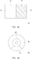
- FIG. 2A is a schematic diagram of a transfer region and a light splitting region of a light splitting module of FIG. 1 .
- FIG. 2B is a front view of a wavelength conversion module of FIG. 1 .
- FIG. 3A is a schematic diagram of an optical path of a wavelength converted beam of an illumination system of FIG. 1 .
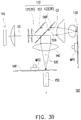
- FIG. 3B is a schematic diagram of an optical path of an excitation beam passing through the light splitting module of FIG. 2A .
- the projection apparatus 200 includes an illumination system 100, a light valve 210 and a projection lens 220.
- the light valve 210 is, for example, a Digital Micro-mirror Device (DMD) or a Liquid-Crystal-On-Silicon (LCOS) panel.
- DMD Digital Micro-mirror Device
- LCOS Liquid-Crystal-On-Silicon
- the light valve 210 may also be a transmissive liquid crystal panel or other beam modulator.
- the number of the light valve 210 may be one or plural.
- the illumination system 100 is configured to provide an illumination beam 70, and the illumination system 100 includes an excitation light source 110, a light splitting module 120, a wavelength conversion module 130, a light converging element 140 and a light homogenizing element 150.
- the excitation light source 110 is configured to emit an excitation beam 50.
- the excitation light source 110 is a blue laser light source
- the excitation beam 50 is a blue laser beam, i.e. a beam with a blue waveband.
- the excitation light source 110 for example, includes a plurality of blue laser diodes arranged in an array (not shown), though the invention is not limited thereto.
- the light splitting module 120 is located on the transmission path of the excitation beam 50, and is located between the excitation light source 110 and the wavelength conversion module 130, where the light splitting module 120 has a transfer region TR and a light splitting region SR.
- the excitation beam 50 emitted from the excitation light source 110 is incident to the wavelength conversion module 130 through the transfer region TR.
- the excitation beam 50 passing through the light splitting region SR forms a first sub-excitation beam 50A and a second sub-excitation beam 50B.
- the light splitting module 120 includes a dichroic element 121, a light splitting element 122 and a reflection element 123 (for example, a reflection mirror). As shown in FIG. 1 and FIG. 2A , the light splitting element 122 is connected to the dichroic element 121, and the dichroic element 121 and the light splitting element 122 are coplanar. In other words, in the embodiment, surfaces of the dichroic element 121 and the light splitting element 122 facing the wavelength conversion module 130 commonly form an optical surface OS.
- the dichroic element 121 is disposed corresponding to the transfer region TR, and is configured to transmit the excitation beam 50 to the wavelength conversion module 130.
- the dichroic element 121 is pervious to a blue beam (a beam having a blue waveband), and provides a reflection function to other colors (for example, red, green, yellow, etc.) of beams.
- the dichroic element 121 is pervious to the blue laser beam 50. In this way, the laser beam 50 may penetrate through the dichroic element 121 and is incident to the wavelength conversion module 130.
- the wavelength conversion module 130 is located on the transmission path of the excitation beam 50, and has at least one wavelength conversion region WR and a reflection region RR.
- the wavelength conversion module 130 may include a substrate, and the substrate is made of a material with high reflectivity.
- the wavelength conversion region WR may include a wavelength conversion layer (not shown), and is configured to convert the excitation beam 50 into at least one wavelength converted beam 60, i.e. the wavelength conversion layer is irradiated by the excitation beam 50 to form the at least one wavelength converted beam 60.
- the reflection region RR may also include a high reflectivity coating or high reflectivity mirror (not shown), and is configured to reflect the excitation beam 50.
- the wavelength conversion module 130 further includes a first actuator MR1 (for example, a motor) configured to drive the reflection region RR and the at least one wavelength conversion region WR of the wavelength conversion module 130 to enter an irradiation range of the excitation beam 50 at different time, i.e. the reflection region RR and the at least one wavelength conversion region WR of the wavelength conversion module 130 are cut into the transmission path of the excitation beam 50 in turns, such that the excitation beam 50 selectively pass through or is converted into the at least one wavelength converted beam 60.
- a first actuator MR1 for example, a motor
- the at least one wavelength conversion region WR of the wavelength conversion module 130 when the at least one wavelength conversion region WR of the wavelength conversion module 130 enters the irradiation range of the excitation beam 50, the at least one wavelength conversion region WR of the wavelength conversion module 130 converts the excitation beam 50 into the at least one wavelength converted beam 60, and the at least one wavelength converted beam 60 is transmitted to the light splitting module 120 and reflected by the light splitting module 120.
- the reflection region RR of the wavelength conversion module 130 is configured to reflect the excitation beam 50, such that the excitation beam 50 is again transmitted to the light splitting module 120.
- the light splitting element 122 is a transflective element, and is disposed corresponding to the light splitting region SR, and is configured to transform a part of the excitation beam 50 transmitted to the light splitting element 122 into a first sub-excitation beam 50A and transform another part thereof into a second sub-excitation beam 50B, and the light splitting element 122 may provide a reflection function to other colors (for example, red, green, yellow, etc.) of beams.
- the excitation beam 50 coming from the wavelength conversion module 130 forms the first sub-excitation beam 50A and the second sub-excitation beam 50B after passing through the light splitting region SR (i.e.
- the light splitting element 122) of the light splitting module 120 and the at least one wavelength converted beam 60 is reflected.
- the first sub-excitation beam 50A is reflected to the light converging element 140 by the light splitting element 122, and the reflection element 123 of the light splitting module 120 is located on a transmission path of the second sub-excitation beam 50B, so that the second sub-excitation beam 50B is reflected by the reflection element 123 to penetrate through the dichroic element 121 and is transmitted to the light converting element 140.
- the light converging element 140 is located on the transmission path of the first sub-excitation beam 50A, the second sub-excitation beam 50B and the at least one wavelength converted beam 60.
- the at least one wavelength converted beam 60 is reflected by the light splitting element 122 and the dichroic element 121, and is converged to the light homogenizing element 150 through the light converging element 140.
- FIG. 3A in the embodiment, the at least one wavelength converted beam 60 is reflected by the light splitting element 122 and the dichroic element 121, and is converged to the light homogenizing element 150 through the light converging element 140.
- the first sub-excitation beam 50A and the second sub-excitation beam 50B form an excitation combination beam 50C through the light converging element 140, and the excitation combination beam 50C is converged to the light homogenizing element 150.
- the light homogenizing element 150 is located on a transmission path of the excitation combination beam 50C and the at least one wavelength converted beam 60.
- the light homogenizing element 150 is, for example, an integration rod, though the invention is not limited thereto.
- the light homogenizing element 150 homogenizes the illumination beam 70 formed by the excitation combination beam 50C and the at least one wavelength converted beam 60, and transmits the illumination beam 70 to the light valve 210.
- the illumination system 100 may adjust a weight distribution of different angles of the excitation combination beam 50C incident to the light homogenizing element 150 by controlling a transmittance of the light splitting element 122.
- the transmittance of the light splitting element 122 for light without polarization polarity (an average of a P-wave polarized light transmittance and S-wave polarized light transmittance) may be selectively between 10%-90%.
- the transmittance of the light splitting element 122 for light with a P-polarization state is selectively between 10%-90%, or the transmittance of the light splitting element 122 for light with an S-polarization state is selectively between 10%-90%.
- the transmittance of the light splitting element 122 could be controlled based on a polarization characteristic of the excitation beam, and thereby the transmittance of the excitation beam 50 penetrating through the light splitting element 122 would be between 10% and 90%. Therefore, a light splitting effect of the light splitting region SR (i.e. the light splitting element 122) of the light splitting module 120 is obvious, and the excitation beam 50 may be effectively split into a plurality of beams incident to the light homogenizing element in different angles.
- the illumination system 100 may also adjust the weight distribution of different angles of the excitation combination beam 50C incident to the light homogenizing element 150 by adjusting a proportion of the transfer region TR or the light splitting region SR of the light splitting module 120 occupying on the optical surface OS.
- the proportion of the transfer region TR of the light splitting module 120 occupying on the optical surface OS is between 25% and 75%.
- the transfer region TR or the light splitting region SR of the light splitting module 120 occupies at least 25% of the area of the optical surface OS.
- an angle of the excitation combination beam 50C incident to the light homogenizing element 150 is 0.25 times larger than an angle of the at least one wavelength converted beam 60 incident to the light homogenizing element 150, which avails adjusting uniformity of the illumination beam 70 formed by the excitation combination beam 50C and the at least one wavelength converted beam 60.
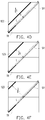
- FIG. 4A to FIG. 4F are structural schematic diagrams of various light splitting modules of FIG. 1 .
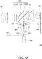
- FIG. 5A and FIG. 5B are distribution schematic diagram of a first light spot region and a second light spot region of FIG. 1 .
- the reflection element 123 and the optical surface OS are disposed in parallel with each other, and a length of linking the dichroic element 121 and the light splitting element 122 on the optical surface OS is a first length L.
- the shortest distance between the reflection element 123 and the optical surface OS may be adjusted between 1/8 of the first length L and 3/8 of the first length L according to the proportion relationship of the transfer region TR and the light splitting region SR of the light splitting module 120, and a proportion of an area of a surface of the reflection element 123 facing the optical surface OS and the area of the optical surface OS may be correspondingly adjusted between 25% and 75%.
- the shortest distance between the reflection element 123 and the optical surface OS may be 1/4 of the first length L, and the proportion of the area of the surface of the reflection element 123 facing the optical surface OS and the area of the optical surface OS may be correspondingly adjusted to 50%.
- the shortest distance between the reflection element 123 and the optical surface OS may be between 1/8 of the first length L and 3/8 of the first length L, and the proportion of the area of the surface of the reflection element 123 facing the optical surface OS and the area of the optical surface OS may be correspondingly adjusted to 25%.
- the shortest distance between the reflection element 123 and the optical surface OS may be between 1/8 of the first length L and 3/8 of the first length L, and the proportion of the area of the surface of the reflection element 123 facing the optical surface OS and the area of the optical surface OS may be correspondingly adjusted between 75% and 25%.
- magnitudes and positions of light spot regions on the light converging element 140 produced by the first sub-excitation beam 50A and the second sub-excitation beam 50B are also varied, which is adapted to control and adjust a position of an optical axis of the excitation combination beam 50C and a range of an irradiation region.
- the first sub-excitation beam 50A may form a first light spot region SP1 on the light converging element 140
- the second sub-excitation beam 50B may form a second light spot region SP2 on the light converging element 140, and the first light spot region SP1 and the second light spot region SP2 are not overlapped with each other.
- the first light spot region SP1 formed by the first sub-excitation beam 50A and the second light spot region SP2 formed by the second sub-excitation beam 50B may be partially overlapped or completely overlapped.
- the distance between the optical axis of the excitation combination beam 50C and the optical axis of the light converging element 140 may also be adjusted.
- the excitation combination beam 50C has a first optical axis O1
- the light converging element 140 has a second optical axis O2
- the angle of the excitation combination beam 50C incident to the light converging element 150 is 0.25 times larger than the angle of the at least one wavelength converted beam 60 incident to the light homogenizing element 150, which avails adjusting uniformity of the illumination beam 70 formed by the excitation combination beam 50C and the at least one wavelength converted beam 60.
- the projection apparatus 200 further includes a filter module 160, where the filter module 160 is located on the transmission path of the excitation combination beam 50C and the at least one wavelength converted beam 60, and has a filter region (not shown) and a transparent region (not shown).
- the filter module 160 further includes a second actuator MR2 configured to drive the filter region (not shown) to correspondingly enter the irradiation range of the wavelength converted beam 60 at different time, so as to respectively form red color light and green color light.
- the transparent region may also correspondingly enter the irradiation range of the excitation combination beam 50C transmitted to the filter module 160 at different time, so as to form blue color light. Therefore, the excitation combination beam 50C and the wavelength converted beam 60 are converted into the illumination beam 70 with a plurality of different colors in timing.
- the filter module 160 is, for example, located between the light converging element 140 and the light homogenizing element 150, though the invention is not limited thereto.
- the light homogenizing element 150 may also be located between the light converging element 140 and the filter module 160.
- the light valve 210 is located on the transmission path of the illumination beam 70, and is configured to convert the illumination beam 70 into an image beam 80.
- the projection lens 220 is located on the transmission path of the image beam 80 and is configured to convert the image beam 80 into a projection beam 90, and projects the projection beam 80 onto a screen (not shown) to form an image.
- the light valve 210 sequentially converts the illumination beam 70 into the image beam 80 of different colors for transmitting to the projection lens 220. Therefore, the image formed by projecting the image beam 80 converted by the light valve 210 becomes a color image.
- the projection apparatus 200 and the illumination system 100 are capable of causing that the angle of the excitation combination beam 50C incident to the light homogenizing element 150 is 0.25 times larger than the angle of the at least one wavelength converted beam 60 incident to the light homogenizing element 150, which avails adjusting uniformity of the illumination beam 70 formed by the excitation combination beam 50C and the at least one wavelength converted beam 60, such that the projected image has good image quality.
- FIG. 6A is a schematic diagram of a transfer region and a light splitting region of another type of the light splitting module of FIG. 1 .
- FIG. 6B is a schematic diagram of an optical path of the excitation beam passing through the light splitting module of FIG. 6A .
- the light splitting module 620 of the embodiment is similar to the light splitting module 120 of FIG. 1 , and differences there between are as follows.
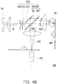
- the light splitting element 622 of the light splitting module 620 has a first region SRI and a second region SR2, where the first region SRI is located between the second region SR2 and the dichroic element 621, and the first region SRI of the light splitting element 622 is coated with a high reflectivity coating used for reflecting the excitation beam 50 transmitted from the wavelength conversion module 130 to form the first sub-excitation beam 50A, and the second region SR2 of the light splitting element 622 is coated with a high transmissive coating used for letting the excitation beam 50 transmitted from the wavelength conversion module 130 to penetrate through to form the second sub-excitation beam 50B, and the second sub-excitation beam 50B is transmitted to the reflection element 623.
- a transmittance of the excitation beam 50 penetrating through the first region SRI of the light splitting element 622 is smaller than 5% (i.e. the reflectivity is greater than 95%), and a transmittance of the excitation beam 50 penetrating through the second region SR2 of the light splitting element 622 is greater than 95%. It should be noted that the above value ranges are only used as an example, and are not used for limiting the invention.
- the angle of the excitation combination beam 50C incident to the light homogenizing element 150 is 0.25 times larger than the angle of the at least one wavelength converted beam 60 incident to the light homogenizing element 150, which avails adjusting uniformity of the illumination beam 70 formed by the excitation combination beam 50C and the at least one wavelength converted beam 60, such that the projected image has good image quality, and the illumination system 100 and the projection apparatus 200 may achieve the similar effects and advantages, which are not repeated.
- FIG. 7 is a structural schematic diagram of another illumination system according to an embodiment of the invention.
- FIG. 8A is a schematic diagram of an optical path of a wavelength converted beam of the illumination system of FIG. 7 .
- FIG. 8B is a schematic diagram of an optical path of an excitation beam of the illumination system of FIG. 7 .
- the illumination system 700 of the embodiment is similar to the illumination system 100 of FIG. 1 , and differences there between are as follows.
- the light splitting module 720 includes a dichroic element 721 and a light splitting element 722.
- the dichroic element 721 corresponds to the transfer region TR, and is configured to reflect the excitation beam 50 coming from the excitation light source 110.
- the dichroic element 721 reflects the blue beam, and allows beams of the other colors (for example, red, green, yellow, etc.) to pass through.
- the excitation beam 50 may also be reflected by the dichroic element 721 to enter the wavelength conversion module 130.
- the at least one wavelength converted beam 60 coming from the wavelength conversion module 130 may pass through the light splitting module 720 for being transmitted to the light converging element 140 and the light homogenizing element 150.
- the light splitting element 722 of the light splitting module 720 corresponds to the light splitting region SR, and the light splitting element 722 is a transflective element, and is configured to transform a part of the excitation beam 50 into a first sub-excitation beam 50A and transform another part thereof into a second sub-excitation beam 50B. Therefore, as shown in FIG. 8B , the excitation beam 50 coming from the reflection region RR of the wavelength conversion module 130 is split into the first sub-excitation beam 50A and the second sub-excitation beam 50B by the light splitting element 722. To be specific, as shown in FIG.
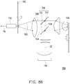
- the first sub-excitation beam 50A is reflected to the dichroic element 721 by the light splitting element 722, and is then reflected by the dichroic element 721 for being transmitted to the light converging element 140, and the second sub-excitation beam 50B is incident to the light converging element 140 and the light homogenizing element 150.
- illumination system 700 is capable of causing that the angle of the excitation combination beam 50C incident to the light homogenizing element 150 is 0.25 times larger than the angle of the at least one wavelength converted beam 60 incident to the light homogenizing element 150, which avails adjusting uniformity of the illumination beam 70 formed by the excitation combination beam 50C and the at least one wavelength converted beam 60, such that the projected image has good image quality, so as to achieve the similar effects and advantages with that of the aforementioned illumination system 100, which are not repeated.
- the projection apparatus 200 may also achieve the similar effects and advantages, and the projected image may have good image quality, which is not repeated.
- the embodiments of the invention include at least one of following advantages or effects.
- the projection apparatus and the illumination system are capable of causing that the angle of the excitation combination beam incident to the light homogenizing element is 0.25 times larger than the angle of the at least one wavelength converted beam incident to the light homogenizing element, which avails adjusting uniformity of the illumination beam formed by the excitation combination beam and the at least one wavelength converted beam, such that a projected image has good image quality.
- the term "the invention”, “the present invention” or the like does not necessarily limit the claim scope to a specific embodiment, and the reference to particularly preferred exemplary embodiments of the invention does not imply a limitation on the invention, and no such limitation is to be inferred.
- the invention is limited only by the scope of the appended claims. Moreover, these claims may refer to use "first”, “second”, etc. following with noun or element. Such terms should be understood as a nomenclature and should not be construed as giving the limitation on the number of the elements modified by such nomenclature unless specific number has been given.
- the abstract of the disclosure is provided to comply with the rules requiring an abstract, which will allow a searcher to quickly ascertain the subject matter of the technical disclosure of any patent issued from this disclosure.
Landscapes
- Physics & Mathematics (AREA)
- General Physics & Mathematics (AREA)
- Engineering & Computer Science (AREA)
- Optics & Photonics (AREA)
- Spectroscopy & Molecular Physics (AREA)
- Multimedia (AREA)
- General Engineering & Computer Science (AREA)
- Projection Apparatus (AREA)
- Non-Portable Lighting Devices Or Systems Thereof (AREA)
Abstract
Description
- This application claims the priority of China application serial no.
201811357470.8 - The invention relates to an illumination system and a projection apparatus.
- In recent years, projection apparatuses using solid state light sources such as Light-Emitting Diode (LED) and laser diodes, etc., have gradually taken a place in the market. Since the laser diode has light-emitting efficiency of higher than 20%, in order to breakthrough a light source limitation of the LED, a technique of using a laser light source to excite phosphor powder to produce a pure light source required by the projection apparatus is gradually developed.
- Generally, the known projection apparatus includes optical elements such as an excitation light source (i.e. a blue light laser array), a phosphor wheel, a filter wheel, an integration rod, a light valve and a projection lens, etc., where after passing through the optical elements, an excitation beam provided by the excitation light source is outputted as a color light in timing through the phosphor wheel and the filter wheel, and after light uniforming and shaping operations of the integration rod, the light valve controls an image gray level, and then the projection lens projects an image. To be specific, when the excitation beam provided by the excitation light source is focused on a region of the phosphor wheel having phosphor powder, an excited beam is produced, and the excited beam is transmitted and focused in the integration rod. On the other hand, when the excitation beam irradiates a region of the phosphor wheel without the phosphor powder, the excitation beam penetrates through the phosphor wheel and is then focused in the integration rod. However, an angle of the excitation beam penetrating through the phosphor wheel incident to the integration rod is much less than an angle of the excited beam incident to the integration rod, which causes a poor color uniformity of a projected image. Moreover, a system optical path of the projection apparatus requires a design of an additional loop, which results in problems of high cost and uneasy to reduce a volume of the system structure.
- The information disclosed in this Background section is only for enhancement of understanding of the background of the described technology and therefore it may contain information that does not form the prior art that is already known to a person of ordinary skill in the art. Further, the information disclosed in the Background section does not mean that one or more problems to be resolved by one or more embodiments of the invention were acknowledged by a person of ordinary skill in the art.
- The invention is directed to an illumination system, which has a small volume.
- The invention is directed to a projection apparatus, which has a small volume and good image quality.
- Other objects and advantages of the invention may be further illustrated by the technical features broadly embodied and described as follows.
- In order to achieve one or a portion of or all of the objects or other objects, an embodiment of the invention provides an illumination system adapted to provide an illumination beam, and the illumination system includes an excitation light source, a wavelength conversion module, a light splitting module and a light homogenizing element. The excitation light source is configured to emit an excitation beam. The wavelength conversion module is located on a transmission path of the excitation beam, and has at least one wavelength conversion region and a reflection region. The light splitting module is located on the transmission path of the excitation beam and located between the excitation light source and the wavelength conversion module, where the light splitting module has a transfer region and a light splitting region, and the excitation beam is incident to the wavelength conversion module through the transfer region, when the at least one wavelength conversion region of the wavelength conversion module is cut into the transmission path of the excitation beam, the excitation beam is converted into at least one wavelength converted beam by the at least one wavelength conversion region of the wavelength conversion module, and when the reflection region of the wavelength conversion module is cut into the transmission path of the excitation beam, the excitation beam is reflected by the reflection region of the wavelength conversion module, and the excitation beam coming from the reflection region of the wavelength conversion module is split into a first sub-excitation beam and a second sub-excitation beam by the light splitting region of the light splitting module, where the first sub-excitation beam and the second sub-excitation beam form an excitation combination beam. The light homogenizing element is located on a transmission path of the excitation combination beam and the at least one wavelength converted beam, and is configured to uniform the excitation combination beam and the at least one wavelength converted beam, where an angle of the excitation combination beam incident to the light homogenizing element is 0.25 times larger than an angle of the at least one wavelength converted beam incident to the light homogenizing element.
- Preferably, the light splitting module may comprise at least one: a dichroic element, corresponding to the transfer region; a light splitting element, connected to the dichroic element, and corresponding to the light splitting region, wherein the first sub-excitation beam is reflected to the light homogenizing element by the light spitting element; and a reflection element, located on a transmission path of the second sub-excitation beam, wherein the second sub-excitation beam is reflected to the light homogenizing element by the reflection element.
- Preferably, the light splitting element may be a transflective element.
- Preferably, the light splitting element may be configured to transform a part of the excitation beam into the first sub-excitation beam and another part thereof into the second sub-excitation beam.
- Preferably, the light splitting element may have a first region and a second region.
- Preferably, the first region may be located between the second region and the dichroic element.
- Preferably, the first region of the light splitting element may be coated with a high reflectivity coating used for reflecting the excitation beam to form the first sub-excitation beam.
- Preferably, the second region of the light splitting element may be coated with a high transmissive coating used for letting the excitation beam to penetrate through to form the second sub-excitation beam.
- Preferably, a transmittance for the excitation beam penetrating through the light splitting element may be between 10% and 90%.
- Preferably, the dichroic element and the light splitting element may be coplanar.
- Preferably, surfaces of the dichroic element and the light splitting element facing the wavelength conversion module commonly may form an optical surface.
- Preferably, a proportion of the transfer region and the optical surface may be between 25% and 75%.
- Preferably, the reflection element and the optical surface may be parallel with each other.
- Preferably, a length of linking the dichroic element and the light splitting element on the optical surface may be a first length, and the shortest distance between the reflection element and the optical surface may be between 1/8 of the first length and 3/8 of the first length.
- Preferably, a proportion of an area of a surface of the reflection element facing the optical surface and an area of the optical surface may be between 25% and 75%.
- Preferably, the illumination system may further comprise at least one of a light converging element, located on a transmission path of the the first sub-excitation beam, the second sub-excitation beam and the at least one wavelength converted beam.
- Preferably, the first sub-excitation beam and the second sub-excitation beam may be converged into the excitation combination beam by the light converging element.
- Preferably, the excitation combination beam may have a first optical axis.
- Preferably, the light converging element may have a second optical axis.
- Preferably, there may be a spacing between the first optical axis of the excitation combination beam and the second optical axis of the light converging element.
- Preferably, the spacing may be smaller than a half of an outer diameter of the light converging element.
- Preferably, the first sub-excitation beam may form a first light spot region on the light converging element.
- Preferably, the second sub-excitation beam may form a second light spot region on the light converging element.
- Preferably, the first light spot region and the second light spot region may be partially overlapped or completely overlapped.
- Preferably, the first sub-excitation beam may form a first light spot region on the light converging element.
- Preferably, the second sub-excitation beam may form a second light spot region on the light converging element.
- Preferably, the first light spot region and the second light spot region may not be overlapped with each other.
- Preferably, the light splitting module may comprises at least one of: a dichroic element, corresponding to the transfer region, and configured to reflect the excitation beam; and a light splitting element, corresponding to the light splitting region, and configured to transform a part of the excitation beam into the first sub-excitation beam and another part thereof into the second sub-excitation beam.
- Preferably, the first sub-excitation beam may be reflected to dichroic element by the light spitting element, and may be transmitted to the light homogenizing element through the dichroic element.
- Preferably, the second sub-excitation beam may be incident to the light homogenizing element.
- An embodiment of the invention provides a projection apparatus. The projection apparatus includes the aforementioned illumination system, a light valve and a projection lens. The light valve is located on the transmission path of the illumination beam, and is configured to convert the illumination beam into an image beam. The projection lens is located on a transmission path of the image beam, and is configured to convert the image beam into a projection beam.
- Based on the above description, the embodiments of the invention include at least one of following advantages or effects. In the embodiments of the invention, through using the configuration of the transfer region and the light splitting region of the light splitting module, the projection apparatus and the illumination system are capable of causing that the angle of the excitation combination beam incident to the light homogenizing element is 0.25 times larger than the angle of the at least one wavelength converted beam incident to the light homogenizing element, which avails adjusting uniformity of the illumination beam formed by the excitation combination beam and the at least one wavelength converted beam, such that a projected image has good image quality.
- Other objectives, features and advantages of the present invention will be further understood from the further technological features disclosed by the embodiments of the invention wherein there are shown and described preferred embodiments of this invention, simply by way of illustration of modes best suited to carry out the invention.
- The accompanying drawings are included to provide a further understanding of the invention, and are incorporated in and constitute a part of this specification. The drawings illustrate embodiments of the invention and, together with the description, serve to explain the principles of the invention.
-
FIG. 1 is a structural schematic diagram of a projection apparatus according to an embodiment of the invention. -
FIG. 2A is a schematic diagram of a transfer region and a light splitting region of a light splitting module ofFIG. 1 . -
FIG. 2B is a front view of a wavelength conversion module ofFIG. 1 . -
FIG. 3A is a schematic diagram of an optical path of a wavelength converted beam of an illumination system ofFIG. 1 . -
FIG. 3B is a schematic diagram of an optical path of an excitation beam passing through a light splitting module ofFIG. 2A . -
FIG.4A to FIG.4F are structural schematic diagrams of various light splitting modules ofFIG. 1 . -
FIG. 5A is a distribution schematic diagram of a first light spot region and a second light spot region ofFIG. 1 . -
FIG. 5B is a distribution schematic diagram of another type of the first light spot region and the second light spot region ofFIG. 1 . -
FIG. 6A is a schematic diagram of a transfer region and a light splitting region of another type of the light splitting module ofFIG. 1 . -
FIG. 6B is a schematic diagram of an optical path of an excitation beam passing through the light splitting module ofFIG. 6A . -
FIG. 7 is a structural schematic diagram of another illumination system according to an embodiment of the invention. -
FIG. 8A is a schematic diagram of an optical path of a wavelength converted beam of the illumination system ofFIG. 7 . -
FIG. 8B is a schematic diagram of an optical path of an excitation beam of the illumination system ofFIG. 7 . - In the following detailed description of the preferred embodiments, reference is made to the accompanying drawings which form a part hereof, and in which are shown by way of illustration specific embodiments in which the invention may be practiced. In this regard, directional terminology, such as "top," "bottom," "front," "back," etc., is used with reference to the orientation of the Figure(s) being described. The components of the present invention can be positioned in a number of different orientations. As such, the directional terminology is used for purposes of illustration and is in no way limiting. On the other hand, the drawings are only schematic and the sizes of components may be exaggerated for clarity. It is to be understood that other embodiments may be utilized and structural changes may be made without departing from the scope of the present invention. Also, it is to be understood that the phraseology and terminology used herein are for the purpose of description and should not be regarded as limiting. The use of "including," "comprising," or "having" and variations thereof herein is meant to encompass the items listed thereafter and equivalents thereof as well as additional items. Unless limited otherwise, the terms "connected," "coupled," and "mounted" and variations thereof herein are used broadly and encompass direct and indirect connections, couplings, and mountings. Similarly, the terms "facing," "faces" and variations thereof herein are used broadly and encompass direct and indirect facing, and "adjacent to" and variations thereof herein are used broadly and encompass directly and indirectly "adjacent to". Therefore, the description of "A" component facing "B" component herein may contain the situations that "A" component directly faces "B" component or one or more additional components are between "A" component and "B" component. Also, the description of "A" component "adjacent to" "B" component herein may contain the situations that "A" component is directly "adjacent to" "B" component or one or more additional components are between "A" component and "B" component. Accordingly, the drawings and descriptions will be regarded as illustrative in nature and not as restrictive.
-
FIG. 1 is a structural schematic diagram of a projection apparatus according to an embodiment of the invention.FIG. 2A is a schematic diagram of a transfer region and a light splitting region of a light splitting module ofFIG. 1 .FIG. 2B is a front view of a wavelength conversion module ofFIG. 1 .FIG. 3A is a schematic diagram of an optical path of a wavelength converted beam of an illumination system ofFIG. 1 .FIG. 3B is a schematic diagram of an optical path of an excitation beam passing through the light splitting module ofFIG. 2A . Referring toFIG. 1 , in the embodiment, theprojection apparatus 200 includes anillumination system 100, alight valve 210 and aprojection lens 220. In the embodiment, thelight valve 210 is, for example, a Digital Micro-mirror Device (DMD) or a Liquid-Crystal-On-Silicon (LCOS) panel. However, in other embodiment, thelight valve 210 may also be a transmissive liquid crystal panel or other beam modulator. The number of thelight valve 210 may be one or plural. - To be specific, as shown in
FIG. 1 , theillumination system 100 is configured to provide anillumination beam 70, and theillumination system 100 includes anexcitation light source 110, alight splitting module 120, awavelength conversion module 130, alight converging element 140 and alight homogenizing element 150. Theexcitation light source 110 is configured to emit anexcitation beam 50. For example, in the embodiment, theexcitation light source 110 is a blue laser light source, and theexcitation beam 50 is a blue laser beam, i.e. a beam with a blue waveband. Theexcitation light source 110, for example, includes a plurality of blue laser diodes arranged in an array (not shown), though the invention is not limited thereto. - Further, as shown in
FIG. 1 ,FIG. 2A and FIG. 2B , in the embodiment, thelight splitting module 120 is located on the transmission path of theexcitation beam 50, and is located between theexcitation light source 110 and thewavelength conversion module 130, where thelight splitting module 120 has a transfer region TR and a light splitting region SR. Theexcitation beam 50 emitted from theexcitation light source 110 is incident to thewavelength conversion module 130 through the transfer region TR. Theexcitation beam 50 passing through the light splitting region SR forms afirst sub-excitation beam 50A and asecond sub-excitation beam 50B. To be specific, as shown inFIG. 1 , in the embodiment, thelight splitting module 120 includes adichroic element 121, alight splitting element 122 and a reflection element 123 (for example, a reflection mirror). As shown inFIG. 1 andFIG. 2A , thelight splitting element 122 is connected to thedichroic element 121, and thedichroic element 121 and thelight splitting element 122 are coplanar. In other words, in the embodiment, surfaces of thedichroic element 121 and thelight splitting element 122 facing thewavelength conversion module 130 commonly form an optical surface OS. - To be specific, as shown in
FIG. 1 , in the embodiment, thedichroic element 121 is disposed corresponding to the transfer region TR, and is configured to transmit theexcitation beam 50 to thewavelength conversion module 130. For example, in the embodiment, thedichroic element 121 is pervious to a blue beam (a beam having a blue waveband), and provides a reflection function to other colors (for example, red, green, yellow, etc.) of beams. Namely, thedichroic element 121 is pervious to theblue laser beam 50. In this way, thelaser beam 50 may penetrate through thedichroic element 121 and is incident to thewavelength conversion module 130. - Then, as shown in
FIG. 1 ,FIG. 2B ,FIG. 3A andFIG. 3B , in the embodiment, thewavelength conversion module 130 is located on the transmission path of theexcitation beam 50, and has at least one wavelength conversion region WR and a reflection region RR. For example, thewavelength conversion module 130 may include a substrate, and the substrate is made of a material with high reflectivity. The wavelength conversion region WR may include a wavelength conversion layer (not shown), and is configured to convert theexcitation beam 50 into at least one wavelength convertedbeam 60, i.e. the wavelength conversion layer is irradiated by theexcitation beam 50 to form the at least one wavelength convertedbeam 60. On the other hand, the reflection region RR may also include a high reflectivity coating or high reflectivity mirror (not shown), and is configured to reflect theexcitation beam 50. Moreover, in the embodiment, thewavelength conversion module 130 further includes a first actuator MR1 (for example, a motor) configured to drive the reflection region RR and the at least one wavelength conversion region WR of thewavelength conversion module 130 to enter an irradiation range of theexcitation beam 50 at different time, i.e. the reflection region RR and the at least one wavelength conversion region WR of thewavelength conversion module 130 are cut into the transmission path of theexcitation beam 50 in turns, such that theexcitation beam 50 selectively pass through or is converted into the at least one wavelength convertedbeam 60. - For example, as shown in
FIG. 2B andFIG. 3A , in the embodiment, when the at least one wavelength conversion region WR of thewavelength conversion module 130 enters the irradiation range of theexcitation beam 50, the at least one wavelength conversion region WR of thewavelength conversion module 130 converts theexcitation beam 50 into the at least one wavelength convertedbeam 60, and the at least one wavelength convertedbeam 60 is transmitted to thelight splitting module 120 and reflected by thelight splitting module 120. On the other hand, as shown inFIG. 2B andFIG. 3B , the reflection region RR of thewavelength conversion module 130 is configured to reflect theexcitation beam 50, such that theexcitation beam 50 is again transmitted to thelight splitting module 120. - Further, as shown in
FIG. 3B , in the embodiment, thelight splitting element 122 is a transflective element, and is disposed corresponding to the light splitting region SR, and is configured to transform a part of theexcitation beam 50 transmitted to thelight splitting element 122 into afirst sub-excitation beam 50A and transform another part thereof into asecond sub-excitation beam 50B, and thelight splitting element 122 may provide a reflection function to other colors (for example, red, green, yellow, etc.) of beams. In other words, theexcitation beam 50 coming from thewavelength conversion module 130 forms thefirst sub-excitation beam 50A and thesecond sub-excitation beam 50B after passing through the light splitting region SR (i.e. the light splitting element 122) of thelight splitting module 120, and the at least one wavelength convertedbeam 60 is reflected. As shown inFIG. 3B , in the embodiment, thefirst sub-excitation beam 50A is reflected to thelight converging element 140 by thelight splitting element 122, and thereflection element 123 of thelight splitting module 120 is located on a transmission path of thesecond sub-excitation beam 50B, so that thesecond sub-excitation beam 50B is reflected by thereflection element 123 to penetrate through thedichroic element 121 and is transmitted to thelight converting element 140. - As shown in
FIG. 3A andFIG. 3B , in the embodiment, thelight converging element 140 is located on the transmission path of thefirst sub-excitation beam 50A, thesecond sub-excitation beam 50B and the at least one wavelength convertedbeam 60. As shown inFIG. 3A , in the embodiment, the at least one wavelength convertedbeam 60 is reflected by thelight splitting element 122 and thedichroic element 121, and is converged to thelight homogenizing element 150 through thelight converging element 140. As shown inFIG. 3B , in the embodiment, thefirst sub-excitation beam 50A and thesecond sub-excitation beam 50B form anexcitation combination beam 50C through thelight converging element 140, and theexcitation combination beam 50C is converged to thelight homogenizing element 150. - Moreover, as shown in
FIG. 3A andFIG. 3B , in the embodiment, thelight homogenizing element 150 is located on a transmission path of theexcitation combination beam 50C and the at least one wavelength convertedbeam 60. In the embodiment, thelight homogenizing element 150 is, for example, an integration rod, though the invention is not limited thereto. To be specific, as shown inFIG. 1 ,FIG. 3A andFIG. 3B , when theexcitation combination beam 50C and the at least one wavelength convertedbeam 60 form theillumination beam 70 in a timing manner and theillumination beam 70 is transmitted to thelight homogenizing element 150, thelight homogenizing element 150 homogenizes theillumination beam 70 formed by theexcitation combination beam 50C and the at least one wavelength convertedbeam 60, and transmits theillumination beam 70 to thelight valve 210. - Further, in the embodiment, the
illumination system 100 may adjust a weight distribution of different angles of theexcitation combination beam 50C incident to thelight homogenizing element 150 by controlling a transmittance of thelight splitting element 122. To be specific, in the embodiment, the transmittance of thelight splitting element 122 for light without polarization polarity (an average of a P-wave polarized light transmittance and S-wave polarized light transmittance) may be selectively between 10%-90%. Moreover, the transmittance of thelight splitting element 122 for light with a P-polarization state is selectively between 10%-90%, or the transmittance of thelight splitting element 122 for light with an S-polarization state is selectively between 10%-90%. In this way, the transmittance of thelight splitting element 122 could be controlled based on a polarization characteristic of the excitation beam, and thereby the transmittance of theexcitation beam 50 penetrating through thelight splitting element 122 would be between 10% and 90%. Therefore, a light splitting effect of the light splitting region SR (i.e. the light splitting element 122) of thelight splitting module 120 is obvious, and theexcitation beam 50 may be effectively split into a plurality of beams incident to the light homogenizing element in different angles. - Moreover, the
illumination system 100 may also adjust the weight distribution of different angles of theexcitation combination beam 50C incident to thelight homogenizing element 150 by adjusting a proportion of the transfer region TR or the light splitting region SR of thelight splitting module 120 occupying on the optical surface OS. For example, in the embodiment, the proportion of the transfer region TR of thelight splitting module 120 occupying on the optical surface OS is between 25% and 75%. When the proportion of the transfer region TR of thelight splitting module 120 occupying on the optical surface OS is between 25% and 75%, the transfer region TR or the light splitting region SR of thelight splitting module 120 occupies at least 25% of the area of the optical surface OS. Therefore, an angle of theexcitation combination beam 50C incident to thelight homogenizing element 150 is 0.25 times larger than an angle of the at least one wavelength convertedbeam 60 incident to thelight homogenizing element 150, which avails adjusting uniformity of theillumination beam 70 formed by theexcitation combination beam 50C and the at least one wavelength convertedbeam 60. - The invention is further described below with reference of
FIG. 4A to FIG. 5B . -
FIG. 4A to FIG. 4F are structural schematic diagrams of various light splitting modules ofFIG. 1 .FIG. 5A andFIG. 5B are distribution schematic diagram of a first light spot region and a second light spot region ofFIG. 1 . As shown inFIG. 1 ,FIG. 4A to FIG. 4F , in the embodiment, thereflection element 123 and the optical surface OS are disposed in parallel with each other, and a length of linking thedichroic element 121 and thelight splitting element 122 on the optical surface OS is a first length L. The shortest distance between thereflection element 123 and the optical surface OS may be adjusted between 1/8 of the first length L and 3/8 of the first length L according to the proportion relationship of the transfer region TR and the light splitting region SR of thelight splitting module 120, and a proportion of an area of a surface of thereflection element 123 facing the optical surface OS and the area of the optical surface OS may be correspondingly adjusted between 25% and 75%. - For example, as shown in
FIG. 4A , when the proportion of the transfer region TR or the light splitting region SR of thelight splitting module 120 on the optical surface OS is all 50%, the shortest distance between thereflection element 123 and the optical surface OS may be 1/4 of the first length L, and the proportion of the area of the surface of thereflection element 123 facing the optical surface OS and the area of the optical surface OS may be correspondingly adjusted to 50%. - On the other hand, as shown in
FIG. 4B to FIG. 4C , when the proportion of the light splitting region SR of thelight splitting module 120 on the optical surface OS is 25%, the shortest distance between thereflection element 123 and the optical surface OS may be between 1/8 of the first length L and 3/8 of the first length L, and the proportion of the area of the surface of thereflection element 123 facing the optical surface OS and the area of the optical surface OS may be correspondingly adjusted to 25%. - On the other hand, as shown in
FIG. 4D to FIG. 4F , when the proportion of the light splitting region SR of thelight splitting module 120 on the optical surface OS is 75%, the shortest distance between thereflection element 123 and the optical surface OS may be between 1/8 of the first length L and 3/8 of the first length L, and the proportion of the area of the surface of thereflection element 123 facing the optical surface OS and the area of the optical surface OS may be correspondingly adjusted between 75% and 25%. - Further, as shown in
FIG. 5A to FIG. 5B , when the distance between thereflection element 123 and the optical surface OS formed by thedichroic element 121 and thelight splitting element 122 is varied, magnitudes and positions of light spot regions on thelight converging element 140 produced by thefirst sub-excitation beam 50A and thesecond sub-excitation beam 50B are also varied, which is adapted to control and adjust a position of an optical axis of theexcitation combination beam 50C and a range of an irradiation region. - For example, as shown in
FIG. 5A , thefirst sub-excitation beam 50A may form a first light spot region SP1 on thelight converging element 140, and thesecond sub-excitation beam 50B may form a second light spot region SP2 on thelight converging element 140, and the first light spot region SP1 and the second light spot region SP2 are not overlapped with each other. On the other hand, as shown inFIG. 5B , when thereflection element 123 is moved towards the optical surface OS, the first light spot region SP1 formed by thefirst sub-excitation beam 50A and the second light spot region SP2 formed by thesecond sub-excitation beam 50B may be partially overlapped or completely overlapped. - Therefore, the distance between the optical axis of the
excitation combination beam 50C and the optical axis of thelight converging element 140 may also be adjusted. For example, as shown inFIG. 5A andFIG. 5B , in the embodiment, theexcitation combination beam 50C has a first optical axis O1, thelight converging element 140 has a second optical axis O2, there is a spacing D between the first optical axis O1 of theexcitation combination beam 50C and the second optical axis O2 of thelight converging element 140, and the spacing D is smaller than a half of an outer diameter R of thelight converging element 140. - Therefore, the angle of the
excitation combination beam 50C incident to thelight converging element 150 is 0.25 times larger than the angle of the at least one wavelength convertedbeam 60 incident to thelight homogenizing element 150, which avails adjusting uniformity of theillumination beam 70 formed by theexcitation combination beam 50C and the at least one wavelength convertedbeam 60. - Referring to
FIG. 1 ,FIG. 3A andFIG. 3B , as shown inFIG. 1 ,FIG. 3A andFIG. 3B , in the embodiment, theprojection apparatus 200 further includes afilter module 160, where thefilter module 160 is located on the transmission path of theexcitation combination beam 50C and the at least one wavelength convertedbeam 60, and has a filter region (not shown) and a transparent region (not shown). Thefilter module 160 further includes a second actuator MR2 configured to drive the filter region (not shown) to correspondingly enter the irradiation range of the wavelength convertedbeam 60 at different time, so as to respectively form red color light and green color light. On the other hand, the transparent region (not shown) may also correspondingly enter the irradiation range of theexcitation combination beam 50C transmitted to thefilter module 160 at different time, so as to form blue color light. Therefore, theexcitation combination beam 50C and the wavelength convertedbeam 60 are converted into theillumination beam 70 with a plurality of different colors in timing. - It should be noted that in the embodiment, the
filter module 160 is, for example, located between the light convergingelement 140 and thelight homogenizing element 150, though the invention is not limited thereto. In another embodiment that is not shown, thelight homogenizing element 150 may also be located between the light convergingelement 140 and thefilter module 160. In this way, theexcitation combination beam 50C and the at least one wavelength convertedbeam 60 are first homogenized by thelight homogenizing element 150, and then pass through thefilter module 160 to form theillumination beam 70, and theillumination beam 70 is transmitted to thelight valve 210. - Then, as shown in
FIG. 1 , thelight valve 210 is located on the transmission path of theillumination beam 70, and is configured to convert theillumination beam 70 into animage beam 80. Theprojection lens 220 is located on the transmission path of theimage beam 80 and is configured to convert theimage beam 80 into aprojection beam 90, and projects theprojection beam 80 onto a screen (not shown) to form an image. After theillumination beam 70 is converged on thelight valve 210, thelight valve 210 sequentially converts theillumination beam 70 into theimage beam 80 of different colors for transmitting to theprojection lens 220. Therefore, the image formed by projecting theimage beam 80 converted by thelight valve 210 becomes a color image. - In this way, through using the configuration of the transfer region TR and the light splitting region SR of the
light splitting module 120, theprojection apparatus 200 and theillumination system 100 are capable of causing that the angle of theexcitation combination beam 50C incident to thelight homogenizing element 150 is 0.25 times larger than the angle of the at least one wavelength convertedbeam 60 incident to thelight homogenizing element 150, which avails adjusting uniformity of theillumination beam 70 formed by theexcitation combination beam 50C and the at least one wavelength convertedbeam 60, such that the projected image has good image quality. -
FIG. 6A is a schematic diagram of a transfer region and a light splitting region of another type of the light splitting module ofFIG. 1 .FIG. 6B is a schematic diagram of an optical path of the excitation beam passing through the light splitting module ofFIG. 6A . Referring toFIG. 6A , thelight splitting module 620 of the embodiment is similar to thelight splitting module 120 ofFIG. 1 , and differences there between are as follows. In the embodiment, thelight splitting element 622 of thelight splitting module 620 has a first region SRI and a second region SR2, where the first region SRI is located between the second region SR2 and thedichroic element 621, and the first region SRI of thelight splitting element 622 is coated with a high reflectivity coating used for reflecting theexcitation beam 50 transmitted from thewavelength conversion module 130 to form thefirst sub-excitation beam 50A, and the second region SR2 of thelight splitting element 622 is coated with a high transmissive coating used for letting theexcitation beam 50 transmitted from thewavelength conversion module 130 to penetrate through to form thesecond sub-excitation beam 50B, and thesecond sub-excitation beam 50B is transmitted to thereflection element 623. For example, in the embodiment, a transmittance of theexcitation beam 50 penetrating through the first region SRI of thelight splitting element 622 is smaller than 5% (i.e. the reflectivity is greater than 95%), and a transmittance of theexcitation beam 50 penetrating through the second region SR2 of thelight splitting element 622 is greater than 95%. It should be noted that the above value ranges are only used as an example, and are not used for limiting the invention. - Therefore, when the
light splitting module 620 is applied to theprojection apparatus 200 and theillumination system 100 ofFIG. 1 , through using the configuration of the transfer region TR and the light splitting region SR, the angle of theexcitation combination beam 50C incident to thelight homogenizing element 150 is 0.25 times larger than the angle of the at least one wavelength convertedbeam 60 incident to thelight homogenizing element 150, which avails adjusting uniformity of theillumination beam 70 formed by theexcitation combination beam 50C and the at least one wavelength convertedbeam 60, such that the projected image has good image quality, and theillumination system 100 and theprojection apparatus 200 may achieve the similar effects and advantages, which are not repeated. -
FIG. 7 is a structural schematic diagram of another illumination system according to an embodiment of the invention.FIG. 8A is a schematic diagram of an optical path of a wavelength converted beam of the illumination system ofFIG. 7 .FIG. 8B is a schematic diagram of an optical path of an excitation beam of the illumination system ofFIG. 7 . Referring toFIG. 7 , theillumination system 700 of the embodiment is similar to theillumination system 100 ofFIG. 1 , and differences there between are as follows. In the embodiment, thelight splitting module 720 includes adichroic element 721 and alight splitting element 722. Thedichroic element 721 corresponds to the transfer region TR, and is configured to reflect theexcitation beam 50 coming from theexcitation light source 110. Namely, in the embodiment, thedichroic element 721 reflects the blue beam, and allows beams of the other colors (for example, red, green, yellow, etc.) to pass through. In this way, theexcitation beam 50 may also be reflected by thedichroic element 721 to enter thewavelength conversion module 130. Then, as shown inFIG. 8A , in the embodiment, the at least one wavelength convertedbeam 60 coming from thewavelength conversion module 130 may pass through thelight splitting module 720 for being transmitted to thelight converging element 140 and thelight homogenizing element 150. - On the other hand, in the embodiment, the
light splitting element 722 of thelight splitting module 720 corresponds to the light splitting region SR, and thelight splitting element 722 is a transflective element, and is configured to transform a part of theexcitation beam 50 into afirst sub-excitation beam 50A and transform another part thereof into asecond sub-excitation beam 50B. Therefore, as shown inFIG. 8B , theexcitation beam 50 coming from the reflection region RR of thewavelength conversion module 130 is split into thefirst sub-excitation beam 50A and thesecond sub-excitation beam 50B by thelight splitting element 722. To be specific, as shown inFIG. 8B , in the embodiment, thefirst sub-excitation beam 50A is reflected to thedichroic element 721 by thelight splitting element 722, and is then reflected by thedichroic element 721 for being transmitted to thelight converging element 140, and thesecond sub-excitation beam 50B is incident to thelight converging element 140 and thelight homogenizing element 150. - In this way, through using the configuration of the transfer region TR (i.e. the dichroic element 721) and the light splitting region SR (i.e. the light splitting element 722), illumination system 700is capable of causing that the angle of the
excitation combination beam 50C incident to thelight homogenizing element 150 is 0.25 times larger than the angle of the at least one wavelength convertedbeam 60 incident to thelight homogenizing element 150, which avails adjusting uniformity of theillumination beam 70 formed by theexcitation combination beam 50C and the at least one wavelength convertedbeam 60, such that the projected image has good image quality, so as to achieve the similar effects and advantages with that of theaforementioned illumination system 100, which are not repeated. Moreover, when theillumination system 700 is applied to theaforementioned projection apparatus 200, theprojection apparatus 200 may also achieve the similar effects and advantages, and the projected image may have good image quality, which is not repeated. - In summary, the embodiments of the invention include at least one of following advantages or effects. In the embodiments of the invention, through using the configuration of the transfer region and the light splitting region of the light splitting module, the projection apparatus and the illumination system are capable of causing that the angle of the excitation combination beam incident to the light homogenizing element is 0.25 times larger than the angle of the at least one wavelength converted beam incident to the light homogenizing element, which avails adjusting uniformity of the illumination beam formed by the excitation combination beam and the at least one wavelength converted beam, such that a projected image has good image quality.
- The foregoing description of the preferred embodiments of the invention has been presented for purposes of illustration and description. It is not intended to be exhaustive or to limit the invention to the precise form or to exemplary embodiments disclosed. Accordingly, the foregoing description should be regarded as illustrative rather than restrictive. Obviously, many modifications and variations will be apparent to practitioners skilled in this art. The embodiments are chosen and described in order to best explain the principles of the invention and its best mode practical application, thereby to enable persons skilled in the art to understand the invention for various embodiments and with various modifications as are suited to the particular use or implementation contemplated. It is intended that the scope of the invention be defined by the claims appended hereto and their equivalents in which all terms are meant in their broadest reasonable sense unless otherwise indicated. Therefore, the term "the invention", "the present invention" or the like does not necessarily limit the claim scope to a specific embodiment, and the reference to particularly preferred exemplary embodiments of the invention does not imply a limitation on the invention, and no such limitation is to be inferred. The invention is limited only by the scope of the appended claims. Moreover, these claims may refer to use "first", "second", etc. following with noun or element. Such terms should be understood as a nomenclature and should not be construed as giving the limitation on the number of the elements modified by such nomenclature unless specific number has been given. The abstract of the disclosure is provided to comply with the rules requiring an abstract, which will allow a searcher to quickly ascertain the subject matter of the technical disclosure of any patent issued from this disclosure. It is submitted with the understanding that it will not be used to interpret or limit the scope or meaning of the claims. Any advantages and benefits described may not apply to all embodiments of the invention. It should be appreciated that variations may be made in the embodiments described by persons skilled in the art without departing from the scope of the present invention as defined by the following claims. Moreover, no element and component in the present disclosure is intended to be dedicated to the public regardless of whether the element or component is explicitly recited in the following claims.
Claims (14)
- An illumination system, adapted to provide an illumination beam, and comprising:an excitation light source (110), configured to emit an excitation beam (50);a wavelength conversion module (130), located on a transmission path of the excitation beam (50), and having at least one wavelength conversion region (WR) and a reflection region (RR);a light splitting module (120) located between the excitation light source (110) and the wavelength conversion module (130),wherein the light splitting module (120) has a transfer region (TR) and a light splitting region (SR), and the excitation beam (50) is incident to the wavelength conversion module (130) through the transfer region (TR),wherein when the at least one wavelength conversion region (WR) of the wavelength conversion module (130) is cut into the transmission path of the excitation beam (50), the excitation beam (50) is converted into at least one wavelength converted beam (60) by the at least one wavelength conversion region (WR) of the wavelength conversion module (130), and when the reflection region (RR) of the wavelength conversion module (130) is cut into the transmission path of the excitation beam (50), the excitation beam (50) is reflected by the reflection region (RR) of the wavelength conversion module (130), and the excitation beam (50) coming from the reflection region (RR) of the wavelength conversion module (130) is split into a first sub-excitation beam (50A) and a second sub-excitation beam (50B) by the light splitting region (SR) of the light splitting module (120), wherein the first sub-excitation beam (50A) and the second sub-excitation beam (50B) form an excitation combination beam (50C); anda light homogenizing element (150), located on a transmission path of the excitation combination beam (50C) and the at least one wavelength converted beam (60), and configured to uniform the excitation combination beam (50C) and the at least one wavelength converted beam (60),wherein an angle of the excitation combination beam (50C) incident to the light homogenizing element (150) is 0.25 times larger than an angle of the at least one wavelength converted beam (60) incident to the light homogenizing element (150).
- The illumination system as claimed in claim 1, wherein the light splitting module (120) comprises:a dichroic element (121), corresponding to the transfer region (TR);a light splitting element (122), connected to the dichroic element (121), and corresponding to the light splitting region (SR),wherein the first sub-excitation beam (50A) is reflected to the light homogenizing element (150) by the light spitting element (122); anda reflection element (123), located on a transmission path of the second sub-excitation beam (50B), wherein the second sub-excitation beam (50B) is reflected to the light homogenizing element (150) by the reflection element (123).
- The illumination system as claimed in claim 2, wherein the light splitting element (122) is a transflective element, and is configured to transform a part of the excitation beam (50) into the first sub-excitation beam (50A) and another part thereof into the second sub-excitation beam (50B).
- The illumination system as claimed in claim 2, wherein the light splitting element (122) has a first region (SRI) and a second region (SR2), wherein the first region (SRI) is located between the second region (SR2) and the dichroic element (121), and the first region (SRI) of the light splitting element (122) is coated with a high reflectivity coating used for reflecting the excitation beam (50) to form the first sub-excitation beam (50A), and the second region (SR2) of the light splitting element (122) is coated with a high transmissive coating used for letting the excitation beam (50) to penetrate through to form the second sub-excitation beam (50B).
- The illumination system as claimed in claim 2, 3 or 4, wherein a transmittance for the excitation beam (50) penetrating through the light splitting element (122) is between 10% and 90%.
- The illumination system as claimed in claim 2, 3, 4 or 5, wherein the dichroic element (121) and the light splitting element (122) are coplanar, surfaces of the dichroic element (121) and the light splitting element (122) facing the wavelength conversion module (130) commonly form an optical surface (OS), and a proportion of the transfer region (TR) and the optical surface (OS) is between 25% and 75%.
- The illumination system as claimed in claim 6, wherein the reflection element (123) and the optical surface (OS) are parallel with each other, and a length of linking the dichroic element (121) and the light splitting element (122) on the optical surface (OS) is a first length, and the shortest distance between the reflection element (123) and the optical surface (OS) is between 1/8 of the first length and 3/8 of the first length.
- The illumination system as claimed in claim 6 or 7, wherein a proportion of an area of a surface of the reflection element (123) facing the optical surface (OS) and an area of the optical surface (OS) is between 25% and 75%.
- The illumination system as claimed in any one of the preceding claims, further comprising:
a light converging element (140), located on a transmission path of the the first sub-excitation beam (50A), the second sub-excitation beam (50B) and the at least one wavelength converted beam (60), wherein the first sub-excitation beam (50A) and the second sub-excitation beam (50B) are converged into the excitation combination beam (50C) by the light converging element (140). - The illumination system as claimed in claim 9, wherein the excitation combination beam (50C) has a first optical axis (O1), the light converging element (140) has a second optical axis (O2), there is a spacing (D) between the first optical axis (O1) of the excitation combination beam (50C) and the second optical axis (O2) of the light converging element (140), and the spacing (D) is smaller than a half of an outer diameter of the light converging element (140).
- The illumination system as claimed in claim 9 or 10, wherein the first sub-excitation beam (50A) forms a first light spot region (SP1) on the light converging element (140), the second sub-excitation beam (50B) forms a second light spot region (SP2) on the light converging element (140), and the first light spot region (SP1) and the second light spot region (SP2) are partially overlapped or completely overlapped.
- The illumination system as claimed in claim 9, 10 or 11, wherein the first sub-excitation beam (50A) forms a first light spot region (SP1) on the light converging element (140), the second sub-excitation beam (50B) forms a second light spot region (SP2) on the light converging element (140), and the first light spot region (SP1) and the second light spot region (SP2) are not overlapped with each other.
- The illumination system as claimed in any one of the preceding claims, wherein the light splitting module (120) comprises:a dichroic element, corresponding to the transfer region (TR), and configured to reflect the excitation beam (50); anda light splitting element (120), corresponding to the light splitting region (SR), and configured to transform a part of the excitation beam (50) into the first sub-excitation beam (50A) and another part thereof into the second sub-excitation beam (50B), wherein the first sub-excitation beam (50A) is reflected to dichroic element (121) by the light spitting element (120), and is transmitted to the light homogenizing element (150) through the dichroic element (121), and the second sub-excitation beam (50B) is incident to the light homogenizing element (150).
- A projection apparatus (200), comprising:
an illumination system as claimed in any one of the preceding claims, the illumination system is adapted to provide an illumination beam (70), and comprising:a light valve (210), located on a transmission path of the illumination beam (70), and configured to convert the illumination beam (70) into an image beam (80);a projection lens (220), located on a transmission path of the image beam (80), and configured to convert the image beam (80) into a projection beam (90).
Applications Claiming Priority (1)
| Application Number | Priority Date | Filing Date | Title |
|---|---|---|---|
| CN201811357470.8A CN111190322A (en) | 2018-11-15 | 2018-11-15 | Illumination system and projection device |
Publications (2)
| Publication Number | Publication Date |
|---|---|
| EP3654100A1 true EP3654100A1 (en) | 2020-05-20 |
| EP3654100B1 EP3654100B1 (en) | 2023-06-28 |
Family
ID=67734506
Family Applications (1)
| Application Number | Title | Priority Date | Filing Date |
|---|---|---|---|
| EP19193022.1A Active EP3654100B1 (en) | 2018-11-15 | 2019-08-22 | Illumination system and projection apparatus |
Country Status (3)
| Country | Link |
|---|---|
| US (1) | US10809607B2 (en) |
| EP (1) | EP3654100B1 (en) |
| CN (2) | CN111190322A (en) |
Cited By (1)
| Publication number | Priority date | Publication date | Assignee | Title |
|---|---|---|---|---|
| EP3964891A1 (en) * | 2020-09-04 | 2022-03-09 | Coretronic Corporation | Illumination system and projection apparatus |
Families Citing this family (11)
| Publication number | Priority date | Publication date | Assignee | Title |
|---|---|---|---|---|
| US11765325B2 (en) * | 2019-11-01 | 2023-09-19 | Texas Instruments Incorporated | Digital display system and method |
| WO2021259270A1 (en) * | 2020-06-22 | 2021-12-30 | 青岛海信激光显示股份有限公司 | Light source assembly and projection device |
| CN114200756B (en) * | 2020-09-18 | 2023-04-18 | 中强光电股份有限公司 | Illumination system and projection device |
| CN213023918U (en) * | 2020-10-26 | 2021-04-20 | 中强光电股份有限公司 | Lighting system and projection device |
| CN114527622B (en) * | 2020-11-23 | 2023-05-26 | 中强光电股份有限公司 | Spectroscopic element and projection device |
| CN114647139B (en) | 2020-12-18 | 2023-08-04 | 中强光电股份有限公司 | Lighting system and projection device |
| CN214751294U (en) | 2021-05-07 | 2021-11-16 | 中强光电股份有限公司 | Lighting system and projection device |
| CN117406540A (en) * | 2022-07-07 | 2024-01-16 | 台达电子工业股份有限公司 | Projector lighting architecture |
| CN117492313A (en) * | 2022-07-26 | 2024-02-02 | 台达电子工业股份有限公司 | Laser light source combining system |
| CN117950256A (en) * | 2022-10-19 | 2024-04-30 | 苏州佳世达光电有限公司 | Projection device |
| WO2025149389A1 (en) * | 2024-01-11 | 2025-07-17 | Signify Holding B.V. | A light generating system |
Citations (5)
| Publication number | Priority date | Publication date | Assignee | Title |
|---|---|---|---|---|
| US20150267880A1 (en) * | 2014-02-05 | 2015-09-24 | Osram Gmbh | Lighting Device Comprising A Wavelength Conversion Arrangement |
| US20150362830A1 (en) * | 2014-06-13 | 2015-12-17 | Coretronic Corporation | Light source module and projection apparatus |
| US20170328540A1 (en) * | 2014-10-29 | 2017-11-16 | Osram Gmbh | Lighting device having a wavelength conversion assembly |
| WO2018166038A1 (en) * | 2017-03-14 | 2018-09-20 | 深圳市光峰光电技术有限公司 | Light source device and projection system |
| US20180284586A1 (en) * | 2017-03-31 | 2018-10-04 | Coretronic Corporation | Projector and illumination system thereof |
Family Cites Families (25)
| Publication number | Priority date | Publication date | Assignee | Title |
|---|---|---|---|---|
| JP4711156B2 (en) * | 2009-06-30 | 2011-06-29 | カシオ計算機株式会社 | Light source device and projector |
| JP5842162B2 (en) | 2011-03-23 | 2016-01-13 | パナソニックIpマネジメント株式会社 | Light source device and image display device using the same |
| CN102707551B (en) | 2011-08-04 | 2015-04-29 | 深圳市光峰光电技术有限公司 | Lighting and Projectors |
| US9816683B2 (en) * | 2011-10-20 | 2017-11-14 | Appotronics Corporation Limited | Light sources system and projection device using the same |
| CN102563410B (en) * | 2011-12-04 | 2014-08-06 | 深圳市光峰光电技术有限公司 | Light emitting device, projection device and lighting device |
| JP5958000B2 (en) | 2012-03-21 | 2016-07-27 | カシオ計算機株式会社 | Light source device and projector |
| JP2013250285A (en) | 2012-05-30 | 2013-12-12 | Hitachi Media Electoronics Co Ltd | Light source device and image display unit |
| JP6056293B2 (en) | 2012-09-12 | 2017-01-11 | 株式会社リコー | Illumination light source device, projection device equipped with this illumination light source device, and control method of projection device |
| JP2014075221A (en) | 2012-10-03 | 2014-04-24 | Mitsubishi Electric Corp | Light source device |
| CN103792768B (en) | 2012-10-31 | 2015-09-09 | 深圳市绎立锐光科技开发有限公司 | Light source system and related projection system |
| DE102013224768B4 (en) | 2013-12-03 | 2023-07-27 | Coretronic Corporation | Light module for a projection device and DLP projector |
| CN109557750B (en) | 2017-09-26 | 2021-06-15 | 中强光电股份有限公司 | Illumination system and projection device using illumination system |
| CN105319819B (en) * | 2014-07-28 | 2019-09-20 | 深圳光峰科技股份有限公司 | Light emitting device and optical projection system |
| CN204593250U (en) | 2015-04-29 | 2015-08-26 | 深圳市光峰光电技术有限公司 | A kind of light guide member and light supply apparatus |
| TWI575299B (en) * | 2015-05-08 | 2017-03-21 | 中強光電股份有限公司 | Illumination system and projection apparatus |
| TWI575300B (en) | 2015-08-31 | 2017-03-21 | 中強光電股份有限公司 | Projection apparatus and illumination system |
| CN108073025B (en) * | 2016-11-18 | 2020-09-04 | 中强光电股份有限公司 | Projection device and illumination system |
| CN206610072U (en) | 2017-03-14 | 2017-11-03 | 深圳市光峰光电技术有限公司 | Light supply apparatus and optical projection system |
| CN206671745U (en) * | 2017-03-14 | 2017-11-24 | 深圳市光峰光电技术有限公司 | Light supply apparatus and optical projection system |
| CN108732852B (en) | 2017-04-14 | 2021-01-05 | 中强光电股份有限公司 | Projector and illumination system thereof |
| CN207457687U (en) * | 2017-09-26 | 2018-06-05 | 深圳市光峰光电技术有限公司 | Light-source system and projector equipment |
| TWM563567U (en) * | 2017-10-09 | 2018-07-11 | 中強光電股份有限公司 | Projector and illumination system thereof |
| CN110874001B (en) * | 2018-08-31 | 2022-07-12 | 中强光电股份有限公司 | Lighting system and projection device |
| JP2020052236A (en) * | 2018-09-27 | 2020-04-02 | キヤノン株式会社 | Light source device and image projection device using the same |
| CN209265161U (en) * | 2018-11-15 | 2019-08-16 | 中强光电股份有限公司 | Lighting system and projection device |
-
2018
- 2018-11-15 CN CN201811357470.8A patent/CN111190322A/en active Pending
- 2018-11-15 CN CN202410016835.XA patent/CN117572714A/en active Pending
-
2019
- 2019-08-22 EP EP19193022.1A patent/EP3654100B1/en active Active
- 2019-08-27 US US16/551,728 patent/US10809607B2/en active Active
Patent Citations (5)
| Publication number | Priority date | Publication date | Assignee | Title |
|---|---|---|---|---|
| US20150267880A1 (en) * | 2014-02-05 | 2015-09-24 | Osram Gmbh | Lighting Device Comprising A Wavelength Conversion Arrangement |
| US20150362830A1 (en) * | 2014-06-13 | 2015-12-17 | Coretronic Corporation | Light source module and projection apparatus |
| US20170328540A1 (en) * | 2014-10-29 | 2017-11-16 | Osram Gmbh | Lighting device having a wavelength conversion assembly |
| WO2018166038A1 (en) * | 2017-03-14 | 2018-09-20 | 深圳市光峰光电技术有限公司 | Light source device and projection system |
| US20180284586A1 (en) * | 2017-03-31 | 2018-10-04 | Coretronic Corporation | Projector and illumination system thereof |
Cited By (2)
| Publication number | Priority date | Publication date | Assignee | Title |
|---|---|---|---|---|
| EP3964891A1 (en) * | 2020-09-04 | 2022-03-09 | Coretronic Corporation | Illumination system and projection apparatus |
| US11860527B2 (en) | 2020-09-04 | 2024-01-02 | Coretronic Corporation | Illumination system and projection apparatus |
Also Published As
| Publication number | Publication date |
|---|---|
| US20200159101A1 (en) | 2020-05-21 |
| US10809607B2 (en) | 2020-10-20 |
| CN117572714A (en) | 2024-02-20 |
| EP3654100B1 (en) | 2023-06-28 |
| CN111190322A (en) | 2020-05-22 |
Similar Documents
| Publication | Publication Date | Title |
|---|---|---|
| US10809607B2 (en) | Illuminaiton system and projection apparatus | |
| US11126073B2 (en) | Illumination system and projection apparatus | |
| US11720009B2 (en) | Illumination system and projection device | |
| US10386710B2 (en) | Projector and illumination system thereof | |
| US11163227B2 (en) | Illumination system, wavelength conversion module, projection apparatus and illumination control method | |
| US10616537B2 (en) | Illumination system and projection apparatus | |
| CN209265161U (en) | Lighting system and projection device | |
| EP3883241B1 (en) | Illumination system and projection device | |
| US10921696B2 (en) | Illumination system and projection apparatus | |
| US9977316B2 (en) | Projection apparatus and illumination system thereof | |
| EP3989000B1 (en) | Projection apparatus and illumination system | |
| US20190391471A1 (en) | Illuminating system and projecting apparatus | |
| US11287735B2 (en) | Diffusion rotating device and projection device | |
| US11126074B2 (en) | Illumination system and projection apparatus | |
| WO2022095504A1 (en) | Light source system and projection device | |
| US11054734B2 (en) | Optical element and projection apparatus | |
| US11405597B2 (en) | Illumination system and projection device | |
| US10921699B2 (en) | Optical rotating device, illumination system and projection device | |
| US10838291B2 (en) | Illumination system and projection device | |
| WO2019148703A1 (en) | Light source device and projection device having same | |
| US11860524B2 (en) | Projection device with high color purity | |
| US11520220B2 (en) | Wavelength conversion module and projection device | |
| US20210041776A1 (en) | Lighting system and projection device | |
| CN219831602U (en) | Light source system and projection equipment | |
| US11693300B2 (en) | Illumination system and projection device |
Legal Events
| Date | Code | Title | Description |
|---|---|---|---|
| PUAI | Public reference made under article 153(3) epc to a published international application that has entered the european phase |
Free format text: ORIGINAL CODE: 0009012 |
|
| STAA | Information on the status of an ep patent application or granted ep patent |
Free format text: STATUS: THE APPLICATION HAS BEEN PUBLISHED |
|
| AK | Designated contracting states |
Kind code of ref document: A1 Designated state(s): AL AT BE BG CH CY CZ DE DK EE ES FI FR GB GR HR HU IE IS IT LI LT LU LV MC MK MT NL NO PL PT RO RS SE SI SK SM TR |
|
| AX | Request for extension of the european patent |
Extension state: BA ME |
|
| STAA | Information on the status of an ep patent application or granted ep patent |
Free format text: STATUS: REQUEST FOR EXAMINATION WAS MADE |
|
| 17P | Request for examination filed |
Effective date: 20201117 |
|
| RBV | Designated contracting states (corrected) |
Designated state(s): AL AT BE BG CH CY CZ DE DK EE ES FI FR GB GR HR HU IE IS IT LI LT LU LV MC MK MT NL NO PL PT RO RS SE SI SK SM TR |
|
| STAA | Information on the status of an ep patent application or granted ep patent |
Free format text: STATUS: EXAMINATION IS IN PROGRESS |
|
| 17Q | First examination report despatched |
Effective date: 20220322 |
|
| GRAP | Despatch of communication of intention to grant a patent |
Free format text: ORIGINAL CODE: EPIDOSNIGR1 |
|
| STAA | Information on the status of an ep patent application or granted ep patent |
Free format text: STATUS: GRANT OF PATENT IS INTENDED |
|
| INTG | Intention to grant announced |
Effective date: 20230130 |
|
| GRAS | Grant fee paid |
Free format text: ORIGINAL CODE: EPIDOSNIGR3 |
|
| GRAA | (expected) grant |
Free format text: ORIGINAL CODE: 0009210 |
|
| STAA | Information on the status of an ep patent application or granted ep patent |
Free format text: STATUS: THE PATENT HAS BEEN GRANTED |
|
| AK | Designated contracting states |
Kind code of ref document: B1 Designated state(s): AL AT BE BG CH CY CZ DE DK EE ES FI FR GB GR HR HU IE IS IT LI LT LU LV MC MK MT NL NO PL PT RO RS SE SI SK SM TR |
|
| REG | Reference to a national code |
Ref country code: CH Ref legal event code: EP |
|
| REG | Reference to a national code |
Ref country code: AT Ref legal event code: REF Ref document number: 1583233 Country of ref document: AT Kind code of ref document: T Effective date: 20230715 |
|
| REG | Reference to a national code |
Ref country code: IE Ref legal event code: FG4D |
|
| REG | Reference to a national code |
Ref country code: DE Ref legal event code: R096 Ref document number: 602019031595 Country of ref document: DE |
|
| REG | Reference to a national code |
Ref country code: LT Ref legal event code: MG9D |
|
| PG25 | Lapsed in a contracting state [announced via postgrant information from national office to epo] |
Ref country code: SE Free format text: LAPSE BECAUSE OF FAILURE TO SUBMIT A TRANSLATION OF THE DESCRIPTION OR TO PAY THE FEE WITHIN THE PRESCRIBED TIME-LIMIT Effective date: 20230628 Ref country code: NO Free format text: LAPSE BECAUSE OF FAILURE TO SUBMIT A TRANSLATION OF THE DESCRIPTION OR TO PAY THE FEE WITHIN THE PRESCRIBED TIME-LIMIT Effective date: 20230928 |
|
| REG | Reference to a national code |
Ref country code: NL Ref legal event code: MP Effective date: 20230628 |
|
| REG | Reference to a national code |
Ref country code: AT Ref legal event code: MK05 Ref document number: 1583233 Country of ref document: AT Kind code of ref document: T Effective date: 20230628 |
|
| PG25 | Lapsed in a contracting state [announced via postgrant information from national office to epo] |
Ref country code: RS Free format text: LAPSE BECAUSE OF FAILURE TO SUBMIT A TRANSLATION OF THE DESCRIPTION OR TO PAY THE FEE WITHIN THE PRESCRIBED TIME-LIMIT Effective date: 20230628 Ref country code: NL Free format text: LAPSE BECAUSE OF FAILURE TO SUBMIT A TRANSLATION OF THE DESCRIPTION OR TO PAY THE FEE WITHIN THE PRESCRIBED TIME-LIMIT Effective date: 20230628 Ref country code: LV Free format text: LAPSE BECAUSE OF FAILURE TO SUBMIT A TRANSLATION OF THE DESCRIPTION OR TO PAY THE FEE WITHIN THE PRESCRIBED TIME-LIMIT Effective date: 20230628 Ref country code: LT Free format text: LAPSE BECAUSE OF FAILURE TO SUBMIT A TRANSLATION OF THE DESCRIPTION OR TO PAY THE FEE WITHIN THE PRESCRIBED TIME-LIMIT Effective date: 20230628 Ref country code: HR Free format text: LAPSE BECAUSE OF FAILURE TO SUBMIT A TRANSLATION OF THE DESCRIPTION OR TO PAY THE FEE WITHIN THE PRESCRIBED TIME-LIMIT Effective date: 20230628 Ref country code: GR Free format text: LAPSE BECAUSE OF FAILURE TO SUBMIT A TRANSLATION OF THE DESCRIPTION OR TO PAY THE FEE WITHIN THE PRESCRIBED TIME-LIMIT Effective date: 20230929 |
|
| PG25 | Lapsed in a contracting state [announced via postgrant information from national office to epo] |
Ref country code: FI Free format text: LAPSE BECAUSE OF FAILURE TO SUBMIT A TRANSLATION OF THE DESCRIPTION OR TO PAY THE FEE WITHIN THE PRESCRIBED TIME-LIMIT Effective date: 20230628 |
|
| PG25 | Lapsed in a contracting state [announced via postgrant information from national office to epo] |
Ref country code: SK Free format text: LAPSE BECAUSE OF FAILURE TO SUBMIT A TRANSLATION OF THE DESCRIPTION OR TO PAY THE FEE WITHIN THE PRESCRIBED TIME-LIMIT Effective date: 20230628 |
|
| PG25 | Lapsed in a contracting state [announced via postgrant information from national office to epo] |
Ref country code: ES Free format text: LAPSE BECAUSE OF FAILURE TO SUBMIT A TRANSLATION OF THE DESCRIPTION OR TO PAY THE FEE WITHIN THE PRESCRIBED TIME-LIMIT Effective date: 20230628 |
|
| PG25 | Lapsed in a contracting state [announced via postgrant information from national office to epo] |
Ref country code: IS Free format text: LAPSE BECAUSE OF FAILURE TO SUBMIT A TRANSLATION OF THE DESCRIPTION OR TO PAY THE FEE WITHIN THE PRESCRIBED TIME-LIMIT Effective date: 20231028 |
|
| PG25 | Lapsed in a contracting state [announced via postgrant information from national office to epo] |
Ref country code: SM Free format text: LAPSE BECAUSE OF FAILURE TO SUBMIT A TRANSLATION OF THE DESCRIPTION OR TO PAY THE FEE WITHIN THE PRESCRIBED TIME-LIMIT Effective date: 20230628 Ref country code: SK Free format text: LAPSE BECAUSE OF FAILURE TO SUBMIT A TRANSLATION OF THE DESCRIPTION OR TO PAY THE FEE WITHIN THE PRESCRIBED TIME-LIMIT Effective date: 20230628 Ref country code: RO Free format text: LAPSE BECAUSE OF FAILURE TO SUBMIT A TRANSLATION OF THE DESCRIPTION OR TO PAY THE FEE WITHIN THE PRESCRIBED TIME-LIMIT Effective date: 20230628 Ref country code: PT Free format text: LAPSE BECAUSE OF FAILURE TO SUBMIT A TRANSLATION OF THE DESCRIPTION OR TO PAY THE FEE WITHIN THE PRESCRIBED TIME-LIMIT Effective date: 20231030 Ref country code: IS Free format text: LAPSE BECAUSE OF FAILURE TO SUBMIT A TRANSLATION OF THE DESCRIPTION OR TO PAY THE FEE WITHIN THE PRESCRIBED TIME-LIMIT Effective date: 20231028 Ref country code: ES Free format text: LAPSE BECAUSE OF FAILURE TO SUBMIT A TRANSLATION OF THE DESCRIPTION OR TO PAY THE FEE WITHIN THE PRESCRIBED TIME-LIMIT Effective date: 20230628 Ref country code: EE Free format text: LAPSE BECAUSE OF FAILURE TO SUBMIT A TRANSLATION OF THE DESCRIPTION OR TO PAY THE FEE WITHIN THE PRESCRIBED TIME-LIMIT Effective date: 20230628 Ref country code: CZ Free format text: LAPSE BECAUSE OF FAILURE TO SUBMIT A TRANSLATION OF THE DESCRIPTION OR TO PAY THE FEE WITHIN THE PRESCRIBED TIME-LIMIT Effective date: 20230628 Ref country code: AT Free format text: LAPSE BECAUSE OF FAILURE TO SUBMIT A TRANSLATION OF THE DESCRIPTION OR TO PAY THE FEE WITHIN THE PRESCRIBED TIME-LIMIT Effective date: 20230628 |
|
| PG25 | Lapsed in a contracting state [announced via postgrant information from national office to epo] |
Ref country code: PL Free format text: LAPSE BECAUSE OF FAILURE TO SUBMIT A TRANSLATION OF THE DESCRIPTION OR TO PAY THE FEE WITHIN THE PRESCRIBED TIME-LIMIT Effective date: 20230628 |
|
| PG25 | Lapsed in a contracting state [announced via postgrant information from national office to epo] |
Ref country code: MC Free format text: LAPSE BECAUSE OF FAILURE TO SUBMIT A TRANSLATION OF THE DESCRIPTION OR TO PAY THE FEE WITHIN THE PRESCRIBED TIME-LIMIT Effective date: 20230628 |
|
| REG | Reference to a national code |
Ref country code: CH Ref legal event code: PL |
|
| PG25 | Lapsed in a contracting state [announced via postgrant information from national office to epo] |
Ref country code: MC Free format text: LAPSE BECAUSE OF FAILURE TO SUBMIT A TRANSLATION OF THE DESCRIPTION OR TO PAY THE FEE WITHIN THE PRESCRIBED TIME-LIMIT Effective date: 20230628 |
|
| REG | Reference to a national code |
Ref country code: DE Ref legal event code: R097 Ref document number: 602019031595 Country of ref document: DE |
|
| PG25 | Lapsed in a contracting state [announced via postgrant information from national office to epo] |
Ref country code: LU Free format text: LAPSE BECAUSE OF NON-PAYMENT OF DUE FEES Effective date: 20230822 |
|
| PG25 | Lapsed in a contracting state [announced via postgrant information from national office to epo] |
Ref country code: LU Free format text: LAPSE BECAUSE OF NON-PAYMENT OF DUE FEES Effective date: 20230822 Ref country code: DK Free format text: LAPSE BECAUSE OF FAILURE TO SUBMIT A TRANSLATION OF THE DESCRIPTION OR TO PAY THE FEE WITHIN THE PRESCRIBED TIME-LIMIT Effective date: 20230628 Ref country code: CH Free format text: LAPSE BECAUSE OF NON-PAYMENT OF DUE FEES Effective date: 20230831 |
|
| PLBE | No opposition filed within time limit |
Free format text: ORIGINAL CODE: 0009261 |
|
| STAA | Information on the status of an ep patent application or granted ep patent |
Free format text: STATUS: NO OPPOSITION FILED WITHIN TIME LIMIT |
|
| REG | Reference to a national code |
Ref country code: BE Ref legal event code: MM Effective date: 20230831 |
|
| REG | Reference to a national code |
Ref country code: IE Ref legal event code: MM4A |
|
| PG25 | Lapsed in a contracting state [announced via postgrant information from national office to epo] |
Ref country code: IT Free format text: LAPSE BECAUSE OF FAILURE TO SUBMIT A TRANSLATION OF THE DESCRIPTION OR TO PAY THE FEE WITHIN THE PRESCRIBED TIME-LIMIT Effective date: 20230628 |
|
| 26N | No opposition filed |
Effective date: 20240402 |
|
| PG25 | Lapsed in a contracting state [announced via postgrant information from national office to epo] |
Ref country code: IE Free format text: LAPSE BECAUSE OF NON-PAYMENT OF DUE FEES Effective date: 20230822 |
|
| PG25 | Lapsed in a contracting state [announced via postgrant information from national office to epo] |
Ref country code: IE Free format text: LAPSE BECAUSE OF NON-PAYMENT OF DUE FEES Effective date: 20230822 Ref country code: SI Free format text: LAPSE BECAUSE OF FAILURE TO SUBMIT A TRANSLATION OF THE DESCRIPTION OR TO PAY THE FEE WITHIN THE PRESCRIBED TIME-LIMIT Effective date: 20230628 |
|
| PG25 | Lapsed in a contracting state [announced via postgrant information from national office to epo] |
Ref country code: BE Free format text: LAPSE BECAUSE OF NON-PAYMENT OF DUE FEES Effective date: 20230831 |
|
| PG25 | Lapsed in a contracting state [announced via postgrant information from national office to epo] |
Ref country code: BG Free format text: LAPSE BECAUSE OF FAILURE TO SUBMIT A TRANSLATION OF THE DESCRIPTION OR TO PAY THE FEE WITHIN THE PRESCRIBED TIME-LIMIT Effective date: 20230628 |
|
| PG25 | Lapsed in a contracting state [announced via postgrant information from national office to epo] |
Ref country code: BG Free format text: LAPSE BECAUSE OF FAILURE TO SUBMIT A TRANSLATION OF THE DESCRIPTION OR TO PAY THE FEE WITHIN THE PRESCRIBED TIME-LIMIT Effective date: 20230628 |
|
| PG25 | Lapsed in a contracting state [announced via postgrant information from national office to epo] |
Ref country code: CY Free format text: LAPSE BECAUSE OF FAILURE TO SUBMIT A TRANSLATION OF THE DESCRIPTION OR TO PAY THE FEE WITHIN THE PRESCRIBED TIME-LIMIT; INVALID AB INITIO Effective date: 20190822 |
|
| PG25 | Lapsed in a contracting state [announced via postgrant information from national office to epo] |
Ref country code: HU Free format text: LAPSE BECAUSE OF FAILURE TO SUBMIT A TRANSLATION OF THE DESCRIPTION OR TO PAY THE FEE WITHIN THE PRESCRIBED TIME-LIMIT; INVALID AB INITIO Effective date: 20190822 |
|
| PGFP | Annual fee paid to national office [announced via postgrant information from national office to epo] |
Ref country code: DE Payment date: 20250827 Year of fee payment: 7 |
|
| PGFP | Annual fee paid to national office [announced via postgrant information from national office to epo] |
Ref country code: GB Payment date: 20250822 Year of fee payment: 7 |
|
| PGFP | Annual fee paid to national office [announced via postgrant information from national office to epo] |
Ref country code: FR Payment date: 20250821 Year of fee payment: 7 |
|
| PG25 | Lapsed in a contracting state [announced via postgrant information from national office to epo] |
Ref country code: TR Free format text: LAPSE BECAUSE OF FAILURE TO SUBMIT A TRANSLATION OF THE DESCRIPTION OR TO PAY THE FEE WITHIN THE PRESCRIBED TIME-LIMIT Effective date: 20230628 |