EP3654079A1 - System and method for providing flammability protection for plastic optical fiber - Google Patents
System and method for providing flammability protection for plastic optical fiber Download PDFInfo
- Publication number
- EP3654079A1 EP3654079A1 EP19194284.6A EP19194284A EP3654079A1 EP 3654079 A1 EP3654079 A1 EP 3654079A1 EP 19194284 A EP19194284 A EP 19194284A EP 3654079 A1 EP3654079 A1 EP 3654079A1
- Authority
- EP
- European Patent Office
- Prior art keywords
- optical fiber
- plastic optical
- optical
- connector
- star coupler
- Prior art date
- Legal status (The legal status is an assumption and is not a legal conclusion. Google has not performed a legal analysis and makes no representation as to the accuracy of the status listed.)
- Granted
Links
Images




Classifications
-
- G—PHYSICS
- G02—OPTICS
- G02B—OPTICAL ELEMENTS, SYSTEMS OR APPARATUS
- G02B6/00—Light guides; Structural details of arrangements comprising light guides and other optical elements, e.g. couplings
- G02B6/02—Optical fibres with cladding with or without a coating
- G02B6/02033—Core or cladding made from organic material, e.g. polymeric material
-
- G—PHYSICS
- G02—OPTICS
- G02B—OPTICAL ELEMENTS, SYSTEMS OR APPARATUS
- G02B6/00—Light guides; Structural details of arrangements comprising light guides and other optical elements, e.g. couplings
- G02B6/24—Coupling light guides
- G02B6/26—Optical coupling means
-
- G—PHYSICS
- G02—OPTICS
- G02B—OPTICAL ELEMENTS, SYSTEMS OR APPARATUS
- G02B6/00—Light guides; Structural details of arrangements comprising light guides and other optical elements, e.g. couplings
- G02B6/24—Coupling light guides
- G02B6/36—Mechanical coupling means
- G02B6/38—Mechanical coupling means having fibre to fibre mating means
- G02B6/3807—Dismountable connectors, i.e. comprising plugs
- G02B6/3887—Anchoring optical cables to connector housings, e.g. strain relief features
-
- G—PHYSICS
- G02—OPTICS
- G02B—OPTICAL ELEMENTS, SYSTEMS OR APPARATUS
- G02B6/00—Light guides; Structural details of arrangements comprising light guides and other optical elements, e.g. couplings
- G02B6/24—Coupling light guides
- G02B6/42—Coupling light guides with opto-electronic elements
- G02B6/4201—Packages, e.g. shape, construction, internal or external details
-
- G—PHYSICS
- G02—OPTICS
- G02B—OPTICAL ELEMENTS, SYSTEMS OR APPARATUS
- G02B6/00—Light guides; Structural details of arrangements comprising light guides and other optical elements, e.g. couplings
- G02B6/24—Coupling light guides
- G02B6/42—Coupling light guides with opto-electronic elements
- G02B6/4201—Packages, e.g. shape, construction, internal or external details
- G02B6/4256—Details of housings
-
- G—PHYSICS
- G02—OPTICS
- G02B—OPTICAL ELEMENTS, SYSTEMS OR APPARATUS
- G02B6/00—Light guides; Structural details of arrangements comprising light guides and other optical elements, e.g. couplings
- G02B6/44—Mechanical structures for providing tensile strength and external protection for fibres, e.g. optical transmission cables
- G02B6/4401—Optical cables
- G02B6/4402—Optical cables with one single optical waveguide
-
- G—PHYSICS
- G02—OPTICS
- G02B—OPTICAL ELEMENTS, SYSTEMS OR APPARATUS
- G02B6/00—Light guides; Structural details of arrangements comprising light guides and other optical elements, e.g. couplings
- G02B6/44—Mechanical structures for providing tensile strength and external protection for fibres, e.g. optical transmission cables
- G02B6/4401—Optical cables
- G02B6/4429—Means specially adapted for strengthening or protecting the cables
-
- G—PHYSICS
- G02—OPTICS
- G02B—OPTICAL ELEMENTS, SYSTEMS OR APPARATUS
- G02B6/00—Light guides; Structural details of arrangements comprising light guides and other optical elements, e.g. couplings
- G02B6/44—Mechanical structures for providing tensile strength and external protection for fibres, e.g. optical transmission cables
- G02B6/4401—Optical cables
- G02B6/4429—Means specially adapted for strengthening or protecting the cables
- G02B6/443—Protective covering
- G02B6/4431—Protective covering with provision in the protective covering, e.g. weak line, for gaining access to one or more fibres, e.g. for branching or tapping
-
- G—PHYSICS
- G02—OPTICS
- G02B—OPTICAL ELEMENTS, SYSTEMS OR APPARATUS
- G02B6/00—Light guides; Structural details of arrangements comprising light guides and other optical elements, e.g. couplings
- G02B6/44—Mechanical structures for providing tensile strength and external protection for fibres, e.g. optical transmission cables
- G02B6/4401—Optical cables
- G02B6/4429—Means specially adapted for strengthening or protecting the cables
- G02B6/4436—Heat resistant
-
- G—PHYSICS
- G02—OPTICS
- G02B—OPTICAL ELEMENTS, SYSTEMS OR APPARATUS
- G02B6/00—Light guides; Structural details of arrangements comprising light guides and other optical elements, e.g. couplings
- G02B6/44—Mechanical structures for providing tensile strength and external protection for fibres, e.g. optical transmission cables
- G02B6/4439—Auxiliary devices
- G02B6/4459—Ducts; Conduits; Hollow tubes for air blown fibres
-
- G—PHYSICS
- G02—OPTICS
- G02B—OPTICAL ELEMENTS, SYSTEMS OR APPARATUS
- G02B6/00—Light guides; Structural details of arrangements comprising light guides and other optical elements, e.g. couplings
- G02B6/44—Mechanical structures for providing tensile strength and external protection for fibres, e.g. optical transmission cables
- G02B6/4479—Manufacturing methods of optical cables
- G02B6/4486—Protective covering
-
- H—ELECTRICITY
- H04—ELECTRIC COMMUNICATION TECHNIQUE
- H04B—TRANSMISSION
- H04B10/00—Transmission systems employing electromagnetic waves other than radio-waves, e.g. infrared, visible or ultraviolet light, or employing corpuscular radiation, e.g. quantum communication
- H04B10/80—Optical aspects relating to the use of optical transmission for specific applications, not provided for in groups H04B10/03 - H04B10/70, e.g. optical power feeding or optical transmission through water
- H04B10/801—Optical aspects relating to the use of optical transmission for specific applications, not provided for in groups H04B10/03 - H04B10/70, e.g. optical power feeding or optical transmission through water using optical interconnects, e.g. light coupled isolators, circuit board interconnections
-
- H—ELECTRICITY
- H04—ELECTRIC COMMUNICATION TECHNIQUE
- H04Q—SELECTING
- H04Q11/00—Selecting arrangements for multiplex systems
- H04Q11/0001—Selecting arrangements for multiplex systems using optical switching
- H04Q11/0062—Network aspects
- H04Q11/0071—Provisions for the electrical-optical layer interface
-
- G—PHYSICS
- G02—OPTICS
- G02B—OPTICAL ELEMENTS, SYSTEMS OR APPARATUS
- G02B1/00—Optical elements characterised by the material of which they are made; Optical coatings for optical elements
- G02B1/04—Optical elements characterised by the material of which they are made; Optical coatings for optical elements made of organic materials, e.g. plastics
- G02B1/045—Light guides
-
- H—ELECTRICITY
- H04—ELECTRIC COMMUNICATION TECHNIQUE
- H04B—TRANSMISSION
- H04B2210/00—Indexing scheme relating to optical transmission systems
- H04B2210/003—Devices including multiple stages, e.g., multi-stage optical amplifiers or dispersion compensators
-
- H—ELECTRICITY
- H04—ELECTRIC COMMUNICATION TECHNIQUE
- H04Q—SELECTING
- H04Q11/00—Selecting arrangements for multiplex systems
- H04Q11/0001—Selecting arrangements for multiplex systems using optical switching
- H04Q11/0062—Network aspects
- H04Q2011/009—Topology aspects
- H04Q2011/0094—Star
-
- H—ELECTRICITY
- H04—ELECTRIC COMMUNICATION TECHNIQUE
- H04Q—SELECTING
- H04Q2213/00—Indexing scheme relating to selecting arrangements in general and for multiplex systems
- H04Q2213/1301—Optical transmission, optical switches
Definitions
- the technology disclosed herein generally relates to optical networks that enable communication between electrical components and, more particularly, relates to methods for providing flammability protection for components of such optical networks.
- ARINC 629 is a multi-transmitter, shared-bus protocol used for aeronautical and aviation communications networks.
- Existing optical fiber designs for ARINC 629 require major modification and recertification of the line replaceable units (LRUs) with the introduction of fiber optic components that may be used to reduce weight, volume and installation effort, such as transmit and receive fiber optic serial interface modules and changes in the LRU connector to accommodate optical fiber.
- LRUs line replaceable units
- LRU line replaceable unit
- an LRU refers to a modular component of an aircraft, ship or spacecraft (or any other manufactured device) that is designed to be replaced quickly at an operating location.
- an LRU comprises an assembly of optical, electrical and optical-electrical devices contained within a housing which is easily transportable.
- POFC plastic optical fiber converter
- the POFC has a modular housing containing an array of optical-electrical media converters that convert electrical signals (e.g., electrical signals formatted in accordance with the ARINC 629 protocol) from each system LRU into optical signals that can communicate on an optical network using plastic optical fiber (POF).
- electrical signals e.g., electrical signals formatted in accordance with the ARINC 629 protocol
- the POFC system is intended to replace current mode couplers, coupler integration panels, and electrical data bus cables with optical media converters, optical star couplers, and plastic optical fiber for size, weight and power savings and increased reliability.
- the POFC maintains the ARINC 629 end-to-end communication protocol and interfaces between LRUs.
- the conversion to plastic optical fiber is completely transparent to the system LRUs and enables the reuse of existing ARINC 629 equipment onboard an aircraft.
- a plastic optical fiber converter incorporated in an avionics system that complies with the ARINC 629 protocol may be referred to as an "ARINC 629 plastic optical fiber converter".
- the POFC system includes an individually packaged optical-electrical media converter for each channel.
- the POFC system also includes individually packaged optical star couplers. These individually packaged units are interconnected together by fully jacketed POF cables.
- star coupler means a device of a type that receives a plurality of optical signals at an input face via respective input optical fibers and outputs respective portions of each received optical signal to each of a plurality of output optical fibers optically coupled to an output face of the device. Thus each output optical fiber receives respective input optical signals from all of the input optical fibers.
- one star coupler is optically coupled to the transmitters and another star coupler is optically coupled to the receivers of a plurality of optical-electrical media converters to enable a plurality of electronic components (such as LRUs), which are respectively electrically connected to the optical-electrical media converters, to communicate with each other.
- One proposed implementation of a POFC has a pair of POF star couplers housed inside a fully enclosed metal box, each star coupler comprising a tapered optical mixer housed in a holding tube.
- the optical mixers are optically coupled to a multiplicity of POF cables (e.g., having PMMA cores) which must comply with flammability standards.
- the POF cables are installed close to the electronic printed circuit boards (PCBs) of the optical-electrical media converters incorporated in the POFC.
- optical fiber used in commercial aircraft is protected by a thick and heavy cable jacket made of a certified material.
- incorporating certified heavy and thick protection jackets in the POF jumpers for the star couplers inside the POFC is not feasible because of size and cost limitations.
- embedding the POF jumpers with the thick and bulky cable jacket would make the POF cables too rigid and inflexible to make optical connections to the transmitter and receiver inside the POFC.
- the problem is to ensure adequate flammability protection for POF embedded inside avionics LRUs or other equipment used onboard airborne vehicles while avoiding one or more of the difficulties mentioned above.
- the subject matter disclosed in some detail below is directed to methods for providing flammability protection for plastic optical fiber (POF) embedded inside avionics line replaceable units (LRUs) or other equipment used in airborne vehicles such as commercial or fighter aircrafts.
- Standard commercial-off-the-shelf POF does not have a flame-resistant outer jacket for protection of the POF from burning.
- one commercially available POF PMMA core/fluorinated polymer cladding
- the POF components need to be compact and slim.
- a thin and flexible flammability protection tube is placed around POF installed (embedded) inside an electronic LRU or other equipment.
- a very thin (100 to 250 ⁇ m (microns) in wall thickness) polyimide tube is placed outside and around the embedded POF cable.
- the thin-walled polyimide tube does not diminish the flexibility of the POF cable.
- Such polyimide tubing is a low-cost solution to protect the POF cables inside the POFC from burning.
- the fabrication process proposed herein does not affect the optical performance of the POFC; key POFC metrics such as transmitter output power, receiver sensitivity and optical link margin will not be affected by the proposed process.
- a system comprising: a star coupler; a plastic optical fiber cable comprising a plastic optical fiber optically coupled to the star coupler and a jacket that ensheathes the plastic optical fiber, the jacket being disposed adjacent to the star coupler; a protection tube that ensheathes the jacket of the plastic optical fiber cable in an area adjacent to the star coupler; and a connector attached to the plastic optical fiber cable.
- the protection tube is made of a flame-resistant material (e.g., polyimide).
- the protection tube is flexible and has a wall thickness of between 100 and 250 ⁇ m (microns).
- the system may further comprise: an optical-electrical media converter that is optically coupled to the star coupler by way of the plastic optical fiber cable; and a line replaceable unit that is electrically coupled to the optical-electrical media converter.
- Another aspect of the subject matter disclosed in detail below is a method for providing flammability protection to plastic optical fiber, the method comprising: cutting a specified length of tubing made of flame-resistant material to form a protection tube; sliding the protection tube onto a plastic optical fiber cable; sliding a connector onto one end of the plastic optical fiber cable; and attaching the connector to the one end of the plastic optical fiber cable.
- the connector is attached to the one end of the plastic optical fiber cable by crimping.
- the connector may also be crimped onto the protection tube.
- the method may further comprise: optically coupling another end of the plastic optical fiber cable to a star coupler; placing an optical-electrical media converter having a receptacle inside a housing of a modular unit; placing the star coupler, plastic optical fiber cable and connector inside the housing; plugging the connector into the receptacle to optically couple the star coupler to the optical-electrical media converter; closing the housing of the modular unit after the optical-electrical media converter, star coupler, plastic optical fiber cable and connector have been placed inside; and installing the modular unit in an avionics system onboard an aircraft.
- a further aspect of the subject matter disclosed in detail below is a modular component comprising: a housing; an optical-electrical media converter installed inside the housing, the optical-electrical media converter comprising a receptacle; a star coupler installed inside the housing; a plastic optical fiber cable comprising a plastic optical fiber and a jacket that ensheathes the plastic optical fiber, the plastic optical fiber being connected to optically couple the star coupler to the optical-electrical media converter inside the housing; a connector attached to one end of the plastic optical fiber cable and mechanically coupled to the receptacle of the optical-electrical media converter; and a protection tube that ensheathes the jacket of the plastic optical fiber cable, wherein the protection tube is made of a flame-resistant material (e.g., polyimide).
- a flame-resistant material e.g., polyimide
- a fiber optical network for enabling optical communication between line replaceable units on an aircraft will be described in detail below for the purpose of illustration.
- implementation of the fiber optical networks disclosed herein is not limited solely to the environment of an aircraft, but rather may be utilized in fiber optical networks onboard other types of vehicles or fiber optic networks.
- the subject matter disclosed in detail below is directed to an optical network that enables communication between electrical components such as LRUs on an aircraft.
- the optical network includes a transmit star coupler and a receive star coupler, which star couplers are connected to the transmitters and receivers respectively of a plurality of optical-electrical media converters.
- Each optical-electrical media converter comprises a respective receiver optically coupled to the receive star coupler by way of output plastic optical fibers and a respective transmitter optically coupled to the transmit star coupler by way of input plastic optical fibers.
- transmit star coupler means a star coupler in which the attached input plastic optical fibers are optically coupled to transmitters.
- the term “receive star coupler” means a star coupler in which the attached output plastic optical fibers are optically coupled to receivers.
- FIG. 1 is a block diagram representing some components of an avionics system that includes a first plurality of LRUs 18 and a second plurality of LRUs 28 which may communicate with each other via an optical network 80 in accordance with one embodiment.
- the optical network 100 includes a forward POFC 2 and an aft POFC 4.
- the forward POFC 2 and aft POFC 4 communicate via two fiber optical paths 30 and 40.
- the forward POFC 2 includes a transmit star coupler 6a consisting of a transmit optical mixer 12 inside a holding tube 32a (indicated by a dashed rectangle in FIG. 1 ) and a receive star coupler 6b consisting of a receive optical mixer 14 inside a holding tube 32b.
- the forward POFC 2 further includes a first plurality of optical-electrical media converters 16 (respectively identified as OMC-1 to OMC- N in FIG. 1 , where N is a positive integer indicating the number of optical-electrical media converters in the first plurality).
- the first plurality of optical-electrical media converters 16 are optically coupled to the transmit optical mixer 12 and receive optical mixer 14 and electrically coupled to the first plurality of LRUs 18 (respectively identified as LRU-1 to LRU- N in FIG. 1 ), which are external to the forward POFC 2. More specifically, the optical-electrical media converters 16 are: (a) respectively electrically coupled to the line replaceable units 18; (b) optically coupled to transmit optical mixer 12 by way of respective POF cables 36; and (c) optically coupled to receive optical mixer 14 by way of respective POF cables 38. Each of the first plurality of optical-electrical media converters 16 comprises: (a) a respective transmitter (not shown in FIG.
- the aft POFC 4 includes a transmit star coupler 8a consisting of a transmit optical mixer 22 inside a holding tube 34a (indicated by a dashed rectangle in FIG. 1 ) and a receive star coupler 8b consisting of a receive optical mixer 24 inside a holding tube 34b.
- the aft POFC 4 further includes a second plurality of optical-electrical media converters 26 (respectively identified as OMC-1 to OMC- M in FIG.
- the optical-electrical media converters 26 are: (a) respectively electrically coupled to the line replaceable units 28; (b) optically coupled to transmit optical mixer 22 by way of respective POF cables 46; and (c) optically coupled to receive optical mixer 24 by way of respective POF cables 48.
- Each of the second plurality of optical-electrical media converters 26 comprises: (a) a respective transmitter (not shown in FIG.
- the portions of POF cables 36 extending between the first plurality of optical-electrical media converters 16 and the transmit star coupler 6a are ensheathed in fire-resistant material, as will be described in more detail below.
- the portions of POF cables 38 extending between the first plurality of optical-electrical media converters 16 and the receive star coupler 6b are ensheathed in fire-resistant material.
- the forward POFC 2 and aft POFC 4 communicate via two fiber optical paths 30 and 40. More specifically, the transmit optical mixer 12 of the transmit star coupler 6a is optically coupled to the receive optical mixer 24 of the receive star coupler 8b by way of a POF cable 37 disposed inside the housing 10, the fiber optical path 30 disposed outside and between the housings 10 and 20, and a POF cable 49 disposed inside housing 20. Similarly, the transmit optical mixer 22 of the transmit star coupler 8a is optically coupled to the receive optical mixer 14 of the receive star coupler 6b by way of the fiber optical path 40.
- the transmit optical mixer 12 is optically coupled to the receive optical mixer 14 by way of a POF cable 47 disposed inside the housing 20, the fiber optical path 40 disposed outside and between the housings 10 and 20, and a POF cable 39 disposed inside housing 10.
- the POF cable 37 is connected to the fiber optical path 30 by an optical connector 5b; the POF cable 39 is connected to the fiber optical path 40 by an optical connector 5a; the POF cable 47 is connected to the fiber optical path 40 by an optical connector 5c; and the POF cable 49 is connected to the fiber optical path 30 by an optical connector 5d.
- the transmit optical mixer 12 of the transmit star coupler 6a is optically coupled to the receive optical mixer 14 of the receive star coupler 6b by way of a POF cable 50
- the transmit optical mixer 22 of the transmit star coupler 8a is optically coupled to the receive optical mixer 24 of the receive star coupler 8b by way of a POF cable 52.
- portions of the POF cables 37, 39, 47 and 49 disposed outside of the star couplers are also ensheathed in fire-resistant material. More specifically, the ensheathed portions of POF cables 37, 39, 47 and 49 include the following: the portion of POF cable 37 extending from the transmit star coupler 6a to the optical connector 5b; the portion of POF cable 39 extending from the receive star coupler 6b to the optical connector 5a; the portion of POF cable 47 extending from the transmit star coupler 8a to the optical connector 5c; and the portion of POF cable 49 extending from the receive star coupler 8b to the optical connector 5d.
- the transmit optical mixer 12 of the transmit star coupler 6a is configured to be connected to N POF cables 36 on one end and to two plastic optical fibers of the fiber optical paths 30 and 50 on the other end
- the receive optical mixer 14 of the receive star coupler 6b is configured to be connected to N POF cables 38 on one end and to two plastic optical fibers of the fiber optical paths 40 and 50 on the other end.
- Such optical mixers may be referred to as 2 x N optical mixers.
- the transmit optical mixer 22 of the transmit star coupler 8a is configured to be connected to M POF cables 46 on one end and to two plastic optical fibers of the fiber optical paths 40 and 52 on the other end
- the receive optical mixer 24 of the receive star coupler 8b is configured to be connected to M POF cables 48 on one end and to two plastic optical fibers of the fiber optical paths 30 and 52 on the other end.
- Such optical mixers may be referred to as 2 x M optical mixers.
- each signal sent by any one of line replaceable units is received by all of the other line replaceable units.
- an electrical signal is sent by line replaceable unit LRU-1 to optical-electrical media converter OMC-1, which converts the electrical signal into an optical signal that is sent to transmit optical mixer 12 via one of the POF cables 36.
- OMC-1 optical-electrical media converter
- the optical signal is sent to receive optical mixers 14 and 24 via fiber optical paths 50 and 30 respectively.
- the receive optical mixer 14 receives the optical signal via fiber optical path 50 and sends that optical signal along each of the POF cables 38 to all of the optical-electrical media converters 16.
- the receive optical mixer 24 receives the optical signal from transmit optical mixer 12 via fiber optical path 30 and sends that optical signal along each of the POF cables 48 to all of the optical-electrical media converters 26.
- the optical signals are converted into electrical signals and sent to the line replaceable units 28.
- the aft POFC 4 includes a housing 20 in the form of a fully enclosed metal box with no holes because the aft POFC 2 has fewer channels than the forward POFC 2 and operates without forced-air cooling at the back section of the aircraft. Therefore the aft POFC 4 has no flammability certification requirement.
- the forward POFC 2 also includes a housing 10 in the form of a fully enclosed metal box, but has a grid of small holes (not shown in FIG. 1 ) on the top and bottom faces for heat dissipation using forced-air cooling. Because of the small holes in the housing 10 of the forward POFC 2, the POF jumpers 36 used inside the forward POFC 2 are required to be protected for flammability to prevent accidental internal fire spread to adjacent LRUs in the aircraft.
- each of the forward and aft POFCs 2 and 4 is an ARINC 629 data bus LRU which provides data communication between the aircraft's operational LRUs.
- the operational LRUs provide command and control of many aircraft operations, such as monitoring temperature, pressure, humidity, auxiliary power, braking, tires and many other monitoring functions.
- the forward POFC 2 is installed in the front section of the aircraft, whereas the aft POFC 4 which is installed at the back of the aircraft.
- FIG. 1 depicts an optical network 80 having one forward POFC and one aft POFC
- the optical network may have two forward POFCs and one aft POFC, the two forward POFCs and the aft POFC being connected by two pairs of POF cables.
- Each forward POFC has 20 individual optical-electrical media converters which interface with 20 LRUs in the forward section of the aircraft.
- the aft POFC has six individual optical media converters which interface with six LRUs at the back of the aircraft.
- the POF cables 36 and 38 are located inside the metal housing 10.
- Each of the POF cables 36 and 38 has a PMMA acrylic plastic core, fluorinated polymer cladding, and a cross-linked polyethylene outer jacket.
- the POF cables 36 and 38 inside the housing 10 distribute optical signals to and from all the transmitters and receivers in the optical-electrical media converters 16.
- Each optical-electrical media converter 16 includes a respective printed circuit board (PCB) which is electrically connected to an LRU channel.
- PCB printed circuit board
- a thin and flexible flammability protection tube is placed around each of the POF cables 36 and 38 enclosed by the housing 10 of the forward POFC 2.
- a very thin (100 to 250 ⁇ m (microns) in wall thickness) polyimide tube is placed outside and around each embedded POF cable. The thin-walled polyimide tube does not diminish the flexibility of the POF cable.
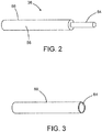
- FIG. 2 is a diagram representing a three-dimensional view of a POF cable 36 comprising a plastic optical fiber 54 surrounded by a jacket 56 made of electrically insulating material (e.g., polyethylene).
- the jacket 56 has a circular cylindrical outer surface 58 with an outer diameter.
- FIG. 3 is a diagram representing a three-dimensional view of a thin flexible protection tube 60 (hereinafter "protection tube 60") made of flame-resistant electrically insulating material.
- the protection tube 60 has a circular cylindrical inner surface 64 with an inner diameter that is slightly greater than the outer diameter of the jacket 56 of the POF cable 36 to allow the protection tube 60 to slide easily onto the jacket 56, thereby providing protection against burning of the POF cable 36 in the event of a fire.
- a protection tube 60 may be selected which has an inner diameter of 1.68 mm, an outer diameter of 2.1 mm, and a wall thickness in a range of 100 to 250 ⁇ m (microns).
- the dimensions of the protection tube 60 may be varied to provide flammability protection to POF cables having different outer diameters.
- the protection tube 60 is made of polyimide.
- Polyimide is a thermoset polymer that has superior thermal stability and chemical resistance and sufficient tensile strength.
- a protection tube 60 made of polyimide is lightweight, flexible, and resistant to heat and chemical interaction.
- Polyimide tubing is commercially available from MicroLumen, Oldsmar, Florida, U.S.A. The effectiveness of these polyimide tubes for flammability protection of the POF cables has been proven in a flammability testing laboratory.
- FIGS. 4A through 4D are diagrams representing respective side views of three POF cables 36a-36c connected to a transmit star coupler 6a at respective stages of a process for providing flammability protection to embedded (enclosed) POF cables in accordance with one embodiment. This process can be applied to any number of POF cables. Only three POF cables 36a-36c are shown in FIGS. 4A-4D to avoid clutter in the drawing.
- the transmit star coupler 6a includes a holding tube 32a in the form of a precision metal cylinder that houses the optical components (e.g., the transmit optical mixer 12).
- a specified length of tubing is cut to form a first protection tube 60a having a first specified length (see FIG. 4A ).
- the first specified length is less than the length of the exposed portion (the portion external to the transmit star coupler 6a) of the POF cable 36a by a specified amount.
- second and third protection tubes (see second and third protection tubes 60b and 60c shown in FIGS. 4C and 4D ) having second and third specified lengths are also cut.
- the second specified length is preferably less than the length of the exposed portion of the POF cable 36b, whereas the third specified length is preferably less than the length of the exposed portion of the POF cable 36c.
- the protection tube 60a is then slid onto the POF cable 36a until one end of the protection tube 60a rests against the transmit star coupler 6a as depicted in FIG. 4B .
- An end section of the POF cable 36a protrudes from the protection tube 60a.
- the second and third protection tubes 60b and 60c may be slid onto the POF cables 36b and 36c respectively.
- FIG. 4C which also shows a plastic optical fiber connector 62 (hereinafter "POF connector 62”) being slid onto the exposed end of the POF cable 36a.
- the POF connector 62 is made of a suitable metal or metal alloy and has a wall thickness selected to enable crimping of the POF connector 62 to the POF cable 36a.
- the POF connector 62 is then crimped to the exposed end of the POF cable 36a, as shown in FIG. 4D .
- the protection tube 60a is now captured between the end face of the transmit star coupler 6a and the POF connector 62.
- the fabrication option partly depicted in FIGS. 4A-4D does not use adhesive bonding to hold the protection tube in place.
- the free end of the POF connector 62 is configured to be plugged into a receptacle (not shown in the drawings) of an optical-electrical media converter 16 (see FIG. 1 ), thereby enabling the optical coupling of the plastic optical fiber of the POF cable 36a to a receiver of the optical-electrical media converter 16 when the forward star coupler 6 is installed inside the housing 10 of the PFOC 2.
- FIG. 4D shows the completed assembly for POF cable 36a. The same four steps are repeated for each POF cable until all of the POF cables have been fitted with a respective protection tube.
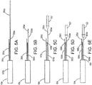
- FIGS. 5A through 5E are diagrams representing respective side views of three POF cables 36a-36c connected to a transmit star coupler 6a at respective stages of a process for providing flammability protection to embedded (enclosed) POF cables in accordance with another embodiment. This process can be applied to any number of POF cables. Only three POF cables 36a-36c are shown in FIGS. 5A-5E to avoid clutter in the drawing. Unlike the fabrication process depicted in FIGS. 4A-4D , the fabrication process depicted in FIGS. 5A-5E uses both adhesive bonding and crimping to hold the protection tube in place.
- a first protection tube 60a having a first specified length is cut (see FIG. 5A ).
- the first specified length is less than the length of the exposed portion (the portion external to the transmit star coupler 6a) of the POF cable 36a by a specified amount.
- second and third protection tubes 60b and 60c having second and third specified lengths are also cut.
- the protection tube 60a is then slid onto the POF cable 36a until one end of the protection tube 60a abuts the end face of the transmit star coupler 6a as depicted in FIG. 5B .
- An end section of the POF cable 36a protrudes from the protection tube 60a.
- the second and third protection tubes 60b and 60c may be slid onto the POF cables 36b and 36c respectively. This stage is shown in FIG. 5C , which also shows a POF connector 62 being slid onto the exposed end of the POF cable 36a.
- the protection tube 60a extends into the crimp region of the POF connector 62.
- the POF connector 62 is then crimped onto both the POF cable 36a and protection tube 60a. This stage is depicted in FIG. 5D .
- the crimp is located on the distal end of the POF connector 62.
- the protective tube 69a is between the POF connector 62 and POF cable 36a.
- FIG. 5E shows the completed assembly for the POF cable 36a.
- One end of the protection tube 60a is bonded to the transmit star coupler 6a and the other end of the protection tube 60a is crimped between the POF connector 62 and the POF cable 36a.
- the same five steps described above may be repeated for each POF cable until all of the POF cables 36 and 38 inside the forward POFC 2 have been fitted with a respective flame-proof protection tube.
- the same five steps described above may be repeated for each POF cable until all of the POF cables 46 and 48 inside the aft POFC 4 have been fitted with a respective flame-proof protection tube.
- the free end of the POF connector 62 is configured to be plugged into a receptacle (not shown in the drawings) of an optical-electrical media converter 16 (see FIG. 1 ), thereby enabling the optical coupling of the plastic optical fiber of the POF cable 36a to a receiver of the optical-electrical media converter 16 when the forward star couplers 6a and 6b are installed inside the housing 10 of the forward POFC 2.
- FIG. 6 is a flowchart identifying steps of a method 100 for providing flammability protection to plastic optical fiber in an avionics systems onboard an aircraft.
- a POF cable is optically coupled to an optical mixer (step 102).
- a specified length of tubing made of flame-resistant material is cut to form a protection tube (step 104).
- the protection tube is then slid onto the POF cable (step 106).
- a connector is slid onto another end of the POF cable (step 108).
- the connector is then attached to the other end of the POF cable (step 110).
- an optical-electrical media converter having a receptacle is placed inside a housing of a modular unit (step 112).
- the optical mixer, plastic optical fiber cable (ensheathed by the protection tube) and connector are placed inside the housing (step 114).
- the connector is plugged into the receptacle to optically couple the optical mixer to the optical-electrical media converter (step 116).
- the housing of the modular unit is closed (step 118) after all of the components (e.g., optical-electrical media converters, optical mixers, plastic optical fiber cables and connectors) have been placed inside.
- the modular unit is installed in an avionics system onboard an aircraft (step 120).
- FIG. 7 is a block diagram identifying some components of a modular unit 90 which may be installed on an aircraft as part of an avionics system. 18.
- the modular component includes a housing 10 and the following components installed inside the housing 10: an optical-electrical media converter 16, a receive star coupler 6b, and a plastic optical fiber cable (not visible in FIG. 7 ) ensheathed by a protection tube 60a.
- the plastic optical fiber cable ensheathed in protection tube 60a optically couples the receive star coupler 6b to the optical-electrical media converter 16 inside the housing 10.
- the modular component 90 may also include a transmit star coupler that is optically coupled to the optical-electrical media converter 16.
- the POF cable ensheathed by protection tube 60a comprises a plastic optical fiber and a jacket that ensheathes the plastic optical fiber.
- the protection tube 60a that ensheathes the jacket of the plastic optical fiber cable is made of a flame-resistant material (e.g., polyimide).
- the receive star coupler 6b may have a first multiplicity of POF cables ensheathed in respective protection tubes 60a connected to one side and a multiplicity of POF cables ensheathed in respective protection tubes 60b (only one of which is shown in FIG. 7 ) connected to the other side.
- the optical-electrical media converter 16 includes a receptacle 74, a photodetector 72 and a receiver printed circuit board (PCB) 70 that is electrically coupled to an LRU 18 which is external to the housing 10.
- the optical-electrical media converter 16 may also include another receptacle, a laser device and a transmitter PCB that is also electrically coupled to the LRU 18.
- the modular unit 90 further includes a POF connector 62 that is mechanically coupled to (e.g., plugged into) the receptacle 74 to optically couple the receive star coupler 6b to the photodetector 72 of the optical-electrical media converter 16 via the POF cable.
- the modular component 90 may also include another connector that is mechanically coupled to (e.g., plugged into) another receptacle to optically couple a transmit star coupler to a laser device of the optical-electrical media converter 16 via another POF cable.
Landscapes
- Physics & Mathematics (AREA)
- Optics & Photonics (AREA)
- General Physics & Mathematics (AREA)
- Engineering & Computer Science (AREA)
- Computer Networks & Wireless Communication (AREA)
- Electromagnetism (AREA)
- Manufacturing & Machinery (AREA)
- Signal Processing (AREA)
- Optical Couplings Of Light Guides (AREA)
- Optical Communication System (AREA)
- Connector Housings Or Holding Contact Members (AREA)
- Mechanical Coupling Of Light Guides (AREA)
- Optical Fibers, Optical Fiber Cores, And Optical Fiber Bundles (AREA)
- Light Guides In General And Applications Therefor (AREA)
Abstract
Description
- The technology disclosed herein generally relates to optical networks that enable communication between electrical components and, more particularly, relates to methods for providing flammability protection for components of such optical networks.
- ARINC 629 is a multi-transmitter, shared-bus protocol used for aeronautical and aviation communications networks. Existing optical fiber designs for ARINC 629 require major modification and recertification of the line replaceable units (LRUs) with the introduction of fiber optic components that may be used to reduce weight, volume and installation effort, such as transmit and receive fiber optic serial interface modules and changes in the LRU connector to accommodate optical fiber.
- As used herein, the term "line replaceable unit" refers to a modular component of an aircraft, ship or spacecraft (or any other manufactured device) that is designed to be replaced quickly at an operating location. Typically, an LRU comprises an assembly of optical, electrical and optical-electrical devices contained within a housing which is easily transportable.
- One example of an LRU employed onboard an aircraft is a plastic optical fiber converter (hereinafter "POFC") that facilitates communications between other operational LRUs. The POFC has a modular housing containing an array of optical-electrical media converters that convert electrical signals (e.g., electrical signals formatted in accordance with the ARINC 629 protocol) from each system LRU into optical signals that can communicate on an optical network using plastic optical fiber (POF).
- The POFC system is intended to replace current mode couplers, coupler integration panels, and electrical data bus cables with optical media converters, optical star couplers, and plastic optical fiber for size, weight and power savings and increased reliability. The POFC maintains the ARINC 629 end-to-end communication protocol and interfaces between LRUs. The conversion to plastic optical fiber is completely transparent to the system LRUs and enables the reuse of existing ARINC 629 equipment onboard an aircraft. A plastic optical fiber converter incorporated in an avionics system that complies with the ARINC 629 protocol may be referred to as an "ARINC 629 plastic optical fiber converter".
- Currently, the POFC system includes an individually packaged optical-electrical media converter for each channel. The POFC system also includes individually packaged optical star couplers. These individually packaged units are interconnected together by fully jacketed POF cables.
- As used herein, the term "star coupler" means a device of a type that receives a plurality of optical signals at an input face via respective input optical fibers and outputs respective portions of each received optical signal to each of a plurality of output optical fibers optically coupled to an output face of the device. Thus each output optical fiber receives respective input optical signals from all of the input optical fibers. In the POFC system, one star coupler is optically coupled to the transmitters and another star coupler is optically coupled to the receivers of a plurality of optical-electrical media converters to enable a plurality of electronic components (such as LRUs), which are respectively electrically connected to the optical-electrical media converters, to communicate with each other.
- One proposed implementation of a POFC has a pair of POF star couplers housed inside a fully enclosed metal box, each star coupler comprising a tapered optical mixer housed in a holding tube. The optical mixers are optically coupled to a multiplicity of POF cables (e.g., having PMMA cores) which must comply with flammability standards. The POF cables are installed close to the electronic printed circuit boards (PCBs) of the optical-electrical media converters incorporated in the POFC.
- In general, optical fiber used in commercial aircraft is protected by a thick and heavy cable jacket made of a certified material. However, incorporating certified heavy and thick protection jackets in the POF jumpers for the star couplers inside the POFC is not feasible because of size and cost limitations. Besides, embedding the POF jumpers with the thick and bulky cable jacket would make the POF cables too rigid and inflexible to make optical connections to the transmitter and receiver inside the POFC.
- The problem is to ensure adequate flammability protection for POF embedded inside avionics LRUs or other equipment used onboard airborne vehicles while avoiding one or more of the difficulties mentioned above.
- The subject matter disclosed in some detail below is directed to methods for providing flammability protection for plastic optical fiber (POF) embedded inside avionics line replaceable units (LRUs) or other equipment used in airborne vehicles such as commercial or fighter aircrafts. Standard commercial-off-the-shelf POF does not have a flame-resistant outer jacket for protection of the POF from burning. For example, one commercially available POF (PMMA core/fluorinated polymer cladding) has a jacket made of polyethylene. In addition, for POF components used inside an electronic LRU which has limited space for the POF components, the POF components need to be compact and slim.
- In accordance with the embodiments of a flammability protection process disclosed herein, a thin and flexible flammability protection tube is placed around POF installed (embedded) inside an electronic LRU or other equipment. In one proposed implementation, a very thin (100 to 250 µm (microns) in wall thickness) polyimide tube is placed outside and around the embedded POF cable. The thin-walled polyimide tube does not diminish the flexibility of the POF cable. Such polyimide tubing is a low-cost solution to protect the POF cables inside the POFC from burning. Moreover, the fabrication process proposed herein does not affect the optical performance of the POFC; key POFC metrics such as transmitter output power, receiver sensitivity and optical link margin will not be affected by the proposed process.
- Although various proposed embodiments of methods and devices for providing embedded POF with flammability protection will be described in some detail below, one or more of those proposed embodiments may be characterized by one or more of the following aspects.
- One aspect of the subject matter disclosed in detail below is a system comprising: a star coupler; a plastic optical fiber cable comprising a plastic optical fiber optically coupled to the star coupler and a jacket that ensheathes the plastic optical fiber, the jacket being disposed adjacent to the star coupler; a protection tube that ensheathes the jacket of the plastic optical fiber cable in an area adjacent to the star coupler; and a connector attached to the plastic optical fiber cable. The protection tube is made of a flame-resistant material (e.g., polyimide). In accordance with some embodiments, the protection tube is flexible and has a wall thickness of between 100 and 250 µm (microns). The system may further comprise: an optical-electrical media converter that is optically coupled to the star coupler by way of the plastic optical fiber cable; and a line replaceable unit that is electrically coupled to the optical-electrical media converter.
- Another aspect of the subject matter disclosed in detail below is a method for providing flammability protection to plastic optical fiber, the method comprising: cutting a specified length of tubing made of flame-resistant material to form a protection tube; sliding the protection tube onto a plastic optical fiber cable; sliding a connector onto one end of the plastic optical fiber cable; and attaching the connector to the one end of the plastic optical fiber cable.
- In accordance with some embodiments of the method described in the immediately preceding paragraph, the connector is attached to the one end of the plastic optical fiber cable by crimping. The connector may also be crimped onto the protection tube.
- The method may further comprise: optically coupling another end of the plastic optical fiber cable to a star coupler; placing an optical-electrical media converter having a receptacle inside a housing of a modular unit; placing the star coupler, plastic optical fiber cable and connector inside the housing; plugging the connector into the receptacle to optically couple the star coupler to the optical-electrical media converter; closing the housing of the modular unit after the optical-electrical media converter, star coupler, plastic optical fiber cable and connector have been placed inside; and installing the modular unit in an avionics system onboard an aircraft.
- A further aspect of the subject matter disclosed in detail below is a modular component comprising: a housing; an optical-electrical media converter installed inside the housing, the optical-electrical media converter comprising a receptacle; a star coupler installed inside the housing; a plastic optical fiber cable comprising a plastic optical fiber and a jacket that ensheathes the plastic optical fiber, the plastic optical fiber being connected to optically couple the star coupler to the optical-electrical media converter inside the housing; a connector attached to one end of the plastic optical fiber cable and mechanically coupled to the receptacle of the optical-electrical media converter; and a protection tube that ensheathes the jacket of the plastic optical fiber cable, wherein the protection tube is made of a flame-resistant material (e.g., polyimide).
- Other aspects of methods and devices for providing embedded POF with flammability protection are disclosed below.
- The features, functions and advantages discussed in the preceding section may be achieved independently in various embodiments or may be combined in yet other embodiments. Various embodiments will be hereinafter described with reference to drawings for the purpose of illustrating the above-described and other aspects. None of the diagrams briefly described in this section are drawn to scale and the relative thicknesses of layers or parts depicted in those diagrams does not precisely reflect the actual thicknesses.
-
FIG. 1 is a block diagram representing some components of an avionics system that includes LRUs which may communicate with each other via an optical network that includes two star couplers in accordance with one proposed implementation for an aircraft. -
FIG. 2 is a diagram representing a three-dimensional view of a POF cable comprising a plastic optical fiber surrounded by a jacket made of electrically insulating material. -
FIG. 3 is a diagram representing a three-dimensional view of a thin flexible protection tube made of flame-resistant electrically insulating material. -
FIGS. 4A through 4D are diagrams representing respective side views of three POF cables connected to a star coupler at respective stages of a process for providing flammability protection to the POF cables in accordance with one embodiment. -
FIGS. 5A through 5E are diagrams representing respective side views of three POF cables connected to a star coupler at respective stages of a process for providing flammability protection to the POF cables in accordance with another embodiment. -
FIG. 6 is a flowchart identifying steps of amethod 100 for providing flammability protection to plastic optical fiber in an avionics systems onboard an aircraft. -
FIG. 7 is a block diagram identifying some components of a modular unit which may be installed on an aircraft as part of an avionics system. - Reference will hereinafter be made to the drawings in which similar elements in different drawings bear the same reference numerals.
- Illustrative embodiments of an avionics system comprising modular units configured to enable various avionics electrical devices to communicate via an optical network are described in some detail below. However, not all features of an actual implementation are described in this specification. A person skilled in the art will appreciate that in the development of any such actual embodiment, numerous implementation-specific decisions must be made to achieve the developer's specific goals, such as compliance with system-related and business-related constraints, which will vary from one implementation to another. Moreover, it will be appreciated that such a development effort might be complex and time-consuming, but would nevertheless be a routine undertaking for those of ordinary skill in the art having the benefit of this disclosure.
- Various embodiments of a fiber optical network for enabling optical communication between line replaceable units on an aircraft will be described in detail below for the purpose of illustration. However, implementation of the fiber optical networks disclosed herein is not limited solely to the environment of an aircraft, but rather may be utilized in fiber optical networks onboard other types of vehicles or fiber optic networks.
- It is known to interconnect line replaceable units on an aircraft using a fiber optical system comprising dual symmetrical star couplers. In some cases, the line replaceable units are connected to optical star couplers via plastic optical fibers. In this manner, the signals sent by each of the line replaceable units are received by all of the other line replaceable units. Some of the line replaceable units are separated by relatively long distances.
- The subject matter disclosed in detail below is directed to an optical network that enables communication between electrical components such as LRUs on an aircraft. The optical network includes a transmit star coupler and a receive star coupler, which star couplers are connected to the transmitters and receivers respectively of a plurality of optical-electrical media converters. Each optical-electrical media converter comprises a respective receiver optically coupled to the receive star coupler by way of output plastic optical fibers and a respective transmitter optically coupled to the transmit star coupler by way of input plastic optical fibers. As used herein, the term "transmit star coupler" means a star coupler in which the attached input plastic optical fibers are optically coupled to transmitters. As used herein, the term "receive star coupler" means a star coupler in which the attached output plastic optical fibers are optically coupled to receivers.
-
FIG. 1 is a block diagram representing some components of an avionics system that includes a first plurality ofLRUs 18 and a second plurality ofLRUs 28 which may communicate with each other via anoptical network 80 in accordance with one embodiment. Theoptical network 100 includes aforward POFC 2 and anaft POFC 4. Theforward POFC 2 and aftPOFC 4 communicate via two fiberoptical paths - The
forward POFC 2 includes a transmitstar coupler 6a consisting of a transmitoptical mixer 12 inside a holdingtube 32a (indicated by a dashed rectangle inFIG. 1 ) and a receivestar coupler 6b consisting of a receiveoptical mixer 14 inside a holdingtube 32b. Theforward POFC 2 further includes a first plurality of optical-electrical media converters 16 (respectively identified as OMC-1 to OMC-N inFIG. 1 , where N is a positive integer indicating the number of optical-electrical media converters in the first plurality). The first plurality of optical-electrical media converters 16 are optically coupled to the transmitoptical mixer 12 and receiveoptical mixer 14 and electrically coupled to the first plurality of LRUs 18 (respectively identified as LRU-1 to LRU-N inFIG. 1 ), which are external to theforward POFC 2. More specifically, the optical-electrical media converters 16 are: (a) respectively electrically coupled to the linereplaceable units 18; (b) optically coupled to transmitoptical mixer 12 by way ofrespective POF cables 36; and (c) optically coupled to receiveoptical mixer 14 by way ofrespective POF cables 38. Each of the first plurality of optical-electrical media converters 16 comprises: (a) a respective transmitter (not shown inFIG. 1 ) that has a laser for converting electrical signals received from a respective linereplaceable unit 18 into optical signals to be sent to transmitoptical mixer 12; and (b) a respective receiver (not shown inFIG. 1 ) that has a photodetector that converts optical signals received from receiveoptical mixer 14 into electrical signals to be sent to a respective linereplaceable unit 18. - The
aft POFC 4 includes a transmitstar coupler 8a consisting of a transmitoptical mixer 22 inside a holdingtube 34a (indicated by a dashed rectangle inFIG. 1 ) and a receivestar coupler 8b consisting of a receiveoptical mixer 24 inside a holdingtube 34b. Theaft POFC 4 further includes a second plurality of optical-electrical media converters 26 (respectively identified as OMC-1 to OMC-M inFIG. 1 , where M is a positive integer indicating the number of optical-electrical media converters in the second plurality) which are optically coupled to the transmitoptical mixer 22 and receiveoptical mixer 24 and electrically coupled to the second plurality of line replaceable units 28 (respectively identified as LRU-1 to LRU-M inFIG. 1 ), which are external to theaft POFC 4. More specifically, the optical-electrical media converters 26 are: (a) respectively electrically coupled to the linereplaceable units 28; (b) optically coupled to transmitoptical mixer 22 by way ofrespective POF cables 46; and (c) optically coupled to receiveoptical mixer 24 by way ofrespective POF cables 48. Each of the second plurality of optical-electrical media converters 26 comprises: (a) a respective transmitter (not shown inFIG. 1 ) that has a laser for converting electrical signals received from a respective linereplaceable unit 28 into optical signals to be sent to transmitoptical mixer 22; and (b) a respective receiver (not shown inFIG. 1 ) that has a photodetector that converts optical signals received from receiveoptical mixer 24 into electrical signals to be sent to a respective linereplaceable unit 28. - In accordance with the embodiments disclosed herein, the portions of
POF cables 36 extending between the first plurality of optical-electrical media converters 16 and the transmitstar coupler 6a are ensheathed in fire-resistant material, as will be described in more detail below. Similarly, the portions ofPOF cables 38 extending between the first plurality of optical-electrical media converters 16 and the receivestar coupler 6b are ensheathed in fire-resistant material. - As mentioned above, the
forward POFC 2 and aftPOFC 4 communicate via two fiberoptical paths optical mixer 12 of the transmitstar coupler 6a is optically coupled to the receiveoptical mixer 24 of the receivestar coupler 8b by way of aPOF cable 37 disposed inside thehousing 10, the fiberoptical path 30 disposed outside and between thehousings POF cable 49 disposed insidehousing 20. Similarly, the transmitoptical mixer 22 of the transmitstar coupler 8a is optically coupled to the receiveoptical mixer 14 of the receivestar coupler 6b by way of the fiberoptical path 40. In addition, the transmitoptical mixer 12 is optically coupled to the receiveoptical mixer 14 by way of aPOF cable 47 disposed inside thehousing 20, the fiberoptical path 40 disposed outside and between thehousings POF cable 39 disposed insidehousing 10. ThePOF cable 37 is connected to the fiberoptical path 30 by anoptical connector 5b; thePOF cable 39 is connected to the fiberoptical path 40 by anoptical connector 5a; thePOF cable 47 is connected to the fiberoptical path 40 by anoptical connector 5c; and thePOF cable 49 is connected to the fiberoptical path 30 by anoptical connector 5d. In addition, the transmitoptical mixer 12 of the transmitstar coupler 6a is optically coupled to the receiveoptical mixer 14 of the receivestar coupler 6b by way of aPOF cable 50, while the transmitoptical mixer 22 of the transmitstar coupler 8a is optically coupled to the receiveoptical mixer 24 of the receivestar coupler 8b by way of aPOF cable 52. - In accordance with the embodiments disclosed herein, portions of the
POF cables POF cables POF cable 37 extending from the transmitstar coupler 6a to theoptical connector 5b; the portion ofPOF cable 39 extending from the receivestar coupler 6b to theoptical connector 5a; the portion ofPOF cable 47 extending from the transmitstar coupler 8a to theoptical connector 5c; and the portion ofPOF cable 49 extending from the receivestar coupler 8b to theoptical connector 5d. - In the particular example embodiment depicted in
FIG. 1 , the transmitoptical mixer 12 of the transmitstar coupler 6a is configured to be connected toN POF cables 36 on one end and to two plastic optical fibers of the fiberoptical paths optical mixer 14 of the receivestar coupler 6b is configured to be connected toN POF cables 38 on one end and to two plastic optical fibers of the fiberoptical paths optical mixer 22 of the transmitstar coupler 8a is configured to be connected toM POF cables 46 on one end and to two plastic optical fibers of the fiberoptical paths optical mixer 24 of the receivestar coupler 8b is configured to be connected toM POF cables 48 on one end and to two plastic optical fibers of the fiberoptical paths - In accordance with the
optical network 80 depicted inFIG. 1 , each signal sent by any one of line replaceable units is received by all of the other line replaceable units. For the sake of illustration, one example data communication using theoptical network 80 depicted inFIG. 1 will now be described. For example, an electrical signal is sent by line replaceable unit LRU-1 to optical-electrical media converter OMC-1, which converts the electrical signal into an optical signal that is sent to transmitoptical mixer 12 via one of thePOF cables 36. From the transmitoptical mixer 12, the optical signal is sent to receiveoptical mixers optical paths optical mixer 14 receives the optical signal via fiberoptical path 50 and sends that optical signal along each of thePOF cables 38 to all of the optical-electrical media converters 16. Those optical signals are converted into electrical signals and sent to the linereplaceable units 18. In the meantime, the receiveoptical mixer 24 receives the optical signal from transmitoptical mixer 12 via fiberoptical path 30 and sends that optical signal along each of thePOF cables 48 to all of the optical-electrical media converters 26. The optical signals are converted into electrical signals and sent to the linereplaceable units 28. - In accordance with one proposed implementation, the
aft POFC 4 includes ahousing 20 in the form of a fully enclosed metal box with no holes because theaft POFC 2 has fewer channels than theforward POFC 2 and operates without forced-air cooling at the back section of the aircraft. Therefore theaft POFC 4 has no flammability certification requirement. Theforward POFC 2 also includes ahousing 10 in the form of a fully enclosed metal box, but has a grid of small holes (not shown inFIG. 1 ) on the top and bottom faces for heat dissipation using forced-air cooling. Because of the small holes in thehousing 10 of theforward POFC 2, thePOF jumpers 36 used inside theforward POFC 2 are required to be protected for flammability to prevent accidental internal fire spread to adjacent LRUs in the aircraft. - In accordance with one proposed implementation, each of the forward and aft POFCs 2 and 4 is an ARINC 629 data bus LRU which provides data communication between the aircraft's operational LRUs. The operational LRUs provide command and control of many aircraft operations, such as monitoring temperature, pressure, humidity, auxiliary power, braking, tires and many other monitoring functions. The
forward POFC 2 is installed in the front section of the aircraft, whereas theaft POFC 4 which is installed at the back of the aircraft. - Although
FIG. 1 depicts anoptical network 80 having one forward POFC and one aft POFC, in an alternative embodiment the optical network may have two forward POFCs and one aft POFC, the two forward POFCs and the aft POFC being connected by two pairs of POF cables. Each forward POFC has 20 individual optical-electrical media converters which interface with 20 LRUs in the forward section of the aircraft. The aft POFC has six individual optical media converters which interface with six LRUs at the back of the aircraft. - In accordance with one proposed implementation of a forward POFC, the
POF cables metal housing 10. Each of thePOF cables POF cables housing 10 distribute optical signals to and from all the transmitters and receivers in the optical-electrical media converters 16. Each optical-electrical media converter 16 includes a respective printed circuit board (PCB) which is electrically connected to an LRU channel. - In accordance with the embodiments of a flammability protection process disclosed herein, a thin and flexible flammability protection tube is placed around each of the
POF cables housing 10 of theforward POFC 2. In one proposed implementation, a very thin (100 to 250 µm (microns) in wall thickness) polyimide tube is placed outside and around each embedded POF cable. The thin-walled polyimide tube does not diminish the flexibility of the POF cable. -
FIG. 2 is a diagram representing a three-dimensional view of aPOF cable 36 comprising a plasticoptical fiber 54 surrounded by ajacket 56 made of electrically insulating material (e.g., polyethylene). Thejacket 56 has a circular cylindricalouter surface 58 with an outer diameter. -
FIG. 3 is a diagram representing a three-dimensional view of a thin flexible protection tube 60 (hereinafter "protection tube 60") made of flame-resistant electrically insulating material. Theprotection tube 60 has a circular cylindricalinner surface 64 with an inner diameter that is slightly greater than the outer diameter of thejacket 56 of thePOF cable 36 to allow theprotection tube 60 to slide easily onto thejacket 56, thereby providing protection against burning of thePOF cable 36 in the event of a fire. - This disclosure proposes methods for incorporating a thin
flexible protection tube 60 on each of thePOF cables forward POFC 2. In the case wherein the maximum outer diameter of thejacket 56 is 1.55 mm, aprotection tube 60 may be selected which has an inner diameter of 1.68 mm, an outer diameter of 2.1 mm, and a wall thickness in a range of 100 to 250 µm (microns). The dimensions of theprotection tube 60 may be varied to provide flammability protection to POF cables having different outer diameters. - In accordance with one proposed implementation, the
protection tube 60 is made of polyimide. Polyimide is a thermoset polymer that has superior thermal stability and chemical resistance and sufficient tensile strength. Aprotection tube 60 made of polyimide is lightweight, flexible, and resistant to heat and chemical interaction. Polyimide tubing is commercially available from MicroLumen, Oldsmar, Florida, U.S.A. The effectiveness of these polyimide tubes for flammability protection of the POF cables has been proven in a flammability testing laboratory. -
FIGS. 4A through 4D are diagrams representing respective side views of threePOF cables 36a-36c connected to a transmitstar coupler 6a at respective stages of a process for providing flammability protection to embedded (enclosed) POF cables in accordance with one embodiment. This process can be applied to any number of POF cables. Only threePOF cables 36a-36c are shown inFIGS. 4A-4D to avoid clutter in the drawing. The transmitstar coupler 6a includes a holdingtube 32a in the form of a precision metal cylinder that houses the optical components (e.g., the transmit optical mixer 12). - First, a specified length of tubing is cut to form a
first protection tube 60a having a first specified length (seeFIG. 4A ). The first specified length is less than the length of the exposed portion (the portion external to the transmitstar coupler 6a) of thePOF cable 36a by a specified amount. Although not shown inFIG. 4A , second and third protection tubes (see second andthird protection tubes FIGS. 4C and 4D ) having second and third specified lengths are also cut. The second specified length is preferably less than the length of the exposed portion of thePOF cable 36b, whereas the third specified length is preferably less than the length of the exposed portion of thePOF cable 36c. - The
protection tube 60a is then slid onto thePOF cable 36a until one end of theprotection tube 60a rests against the transmitstar coupler 6a as depicted inFIG. 4B . An end section of thePOF cable 36a protrudes from theprotection tube 60a. Similarly, the second andthird protection tubes POF cables FIG. 4C , which also shows a plastic optical fiber connector 62 (hereinafter "POF connector 62") being slid onto the exposed end of thePOF cable 36a. ThePOF connector 62 is made of a suitable metal or metal alloy and has a wall thickness selected to enable crimping of thePOF connector 62 to thePOF cable 36a. ThePOF connector 62 is then crimped to the exposed end of thePOF cable 36a, as shown inFIG. 4D . Theprotection tube 60a is now captured between the end face of the transmitstar coupler 6a and thePOF connector 62. The fabrication option partly depicted inFIGS. 4A-4D does not use adhesive bonding to hold the protection tube in place. - The free end of the
POF connector 62 is configured to be plugged into a receptacle (not shown in the drawings) of an optical-electrical media converter 16 (seeFIG. 1 ), thereby enabling the optical coupling of the plastic optical fiber of thePOF cable 36a to a receiver of the optical-electrical media converter 16 when the forward star coupler 6 is installed inside thehousing 10 of thePFOC 2. -
FIG. 4D shows the completed assembly forPOF cable 36a. The same four steps are repeated for each POF cable until all of the POF cables have been fitted with a respective protection tube. -
FIGS. 5A through 5E are diagrams representing respective side views of threePOF cables 36a-36c connected to a transmitstar coupler 6a at respective stages of a process for providing flammability protection to embedded (enclosed) POF cables in accordance with another embodiment. This process can be applied to any number of POF cables. Only threePOF cables 36a-36c are shown inFIGS. 5A-5E to avoid clutter in the drawing. Unlike the fabrication process depicted inFIGS. 4A-4D , the fabrication process depicted inFIGS. 5A-5E uses both adhesive bonding and crimping to hold the protection tube in place. - First, a
first protection tube 60a having a first specified length is cut (seeFIG. 5A ). The first specified length is less than the length of the exposed portion (the portion external to the transmitstar coupler 6a) of thePOF cable 36a by a specified amount. As previously described, second andthird protection tubes - The
protection tube 60a is then slid onto thePOF cable 36a until one end of theprotection tube 60a abuts the end face of the transmitstar coupler 6a as depicted inFIG. 5B . An end section of thePOF cable 36a protrudes from theprotection tube 60a. Similarly, the second andthird protection tubes POF cables FIG. 5C , which also shows aPOF connector 62 being slid onto the exposed end of thePOF cable 36a. - When the
POF connector 62 is assembled onto thePOF cable 36a, theprotection tube 60a extends into the crimp region of thePOF connector 62. ThePOF connector 62 is then crimped onto both thePOF cable 36a andprotection tube 60a. This stage is depicted inFIG. 5D . The crimp is located on the distal end of thePOF connector 62. The protective tube 69a is between thePOF connector 62 andPOF cable 36a. Thus thePOF connector 62 is crimped onto thePOF cable 36a and theprotective tube 60a is held in place by the crimp. - Thereafter the proximal end of the
protection tube 60a is bonded to the optical fiber where the optical fiber exits the star coupler using an epoxy or room temperature-vulcanizing (RTV) adhesive 66. The polyimide tubing can be precut to length before bonding to the star coupler or cut to length after bonding.FIG. 5E shows the completed assembly for thePOF cable 36a. One end of theprotection tube 60a is bonded to the transmitstar coupler 6a and the other end of theprotection tube 60a is crimped between thePOF connector 62 and thePOF cable 36a. - The same five steps described above may be repeated for each POF cable until all of the
POF cables forward POFC 2 have been fitted with a respective flame-proof protection tube. Optionally, the same five steps described above may be repeated for each POF cable until all of thePOF cables aft POFC 4 have been fitted with a respective flame-proof protection tube. - The free end of the
POF connector 62 is configured to be plugged into a receptacle (not shown in the drawings) of an optical-electrical media converter 16 (seeFIG. 1 ), thereby enabling the optical coupling of the plastic optical fiber of thePOF cable 36a to a receiver of the optical-electrical media converter 16 when theforward star couplers housing 10 of theforward POFC 2. - The above-disclosed techniques and processes for flammability protection of POF cable without using heavy and bulky protection jackets is especially suitability for use in avionics systems onboard aircraft.
FIG. 6 is a flowchart identifying steps of amethod 100 for providing flammability protection to plastic optical fiber in an avionics systems onboard an aircraft. First, one end of a POF cable is optically coupled to an optical mixer (step 102). Then a specified length of tubing made of flame-resistant material is cut to form a protection tube (step 104). The protection tube is then slid onto the POF cable (step 106). Afterstep 106 has been performed, a connector is slid onto another end of the POF cable (step 108). The connector is then attached to the other end of the POF cable (step 110). Before or after the assembly of the optical mixer, POF cable, protection tube and connector, an optical-electrical media converter having a receptacle is placed inside a housing of a modular unit (step 112). Afterstep 112 has been performed, the optical mixer, plastic optical fiber cable (ensheathed by the protection tube) and connector are placed inside the housing (step 114). Then the connector is plugged into the receptacle to optically couple the optical mixer to the optical-electrical media converter (step 116). The housing of the modular unit is closed (step 118) after all of the components (e.g., optical-electrical media converters, optical mixers, plastic optical fiber cables and connectors) have been placed inside. Then the modular unit is installed in an avionics system onboard an aircraft (step 120). -
FIG. 7 is a block diagram identifying some components of amodular unit 90 which may be installed on an aircraft as part of an avionics system. 18. The modular component includes ahousing 10 and the following components installed inside the housing 10: an optical-electrical media converter 16, a receivestar coupler 6b, and a plastic optical fiber cable (not visible inFIG. 7 ) ensheathed by aprotection tube 60a. The plastic optical fiber cable ensheathed inprotection tube 60a optically couples the receivestar coupler 6b to the optical-electrical media converter 16 inside thehousing 10. Although not shown inFIG. 7 , themodular component 90 may also include a transmit star coupler that is optically coupled to the optical-electrical media converter 16. - The POF cable ensheathed by
protection tube 60a comprises a plastic optical fiber and a jacket that ensheathes the plastic optical fiber. Theprotection tube 60a that ensheathes the jacket of the plastic optical fiber cable is made of a flame-resistant material (e.g., polyimide). Although not shown inFIG. 7 , the receivestar coupler 6b may have a first multiplicity of POF cables ensheathed inrespective protection tubes 60a connected to one side and a multiplicity of POF cables ensheathed inrespective protection tubes 60b (only one of which is shown inFIG. 7 ) connected to the other side. - The optical-
electrical media converter 16 includes areceptacle 74, aphotodetector 72 and a receiver printed circuit board (PCB) 70 that is electrically coupled to anLRU 18 which is external to thehousing 10. Although not shown inFIG. 7 , the optical-electrical media converter 16 may also include another receptacle, a laser device and a transmitter PCB that is also electrically coupled to theLRU 18. - As seen in
FIG. 7 , themodular unit 90 further includes aPOF connector 62 that is mechanically coupled to (e.g., plugged into) thereceptacle 74 to optically couple the receivestar coupler 6b to thephotodetector 72 of the optical-electrical media converter 16 via the POF cable. Although not shown inFIG. 7 , themodular component 90 may also include another connector that is mechanically coupled to (e.g., plugged into) another receptacle to optically couple a transmit star coupler to a laser device of the optical-electrical media converter 16 via another POF cable. - Further the disclosure comprises embodiments according to the following clauses:
-
Clause 1. A system comprising:- a star coupler;
- a plastic optical fiber cable comprising a plastic optical fiber optically coupled to the star coupler and a jacket that ensheathes the plastic optical fiber, the jacket being disposed adjacent to the star coupler; and
- a protection tube that ensheathes the jacket of the plastic optical fiber cable in an area adjacent to the star coupler,
- wherein the protection tube is made of a flame-resistant material.
-
Clause 2. The system recited inclause 1, wherein the protection tube is flexible and has a wall thickness in a range of 100 to 250 µm (microns). -
Clause 3. The system recited inclause -
Clause 4. The system recited in any ofclauses 1 to 3, further comprising a connector attached to the plastic optical fiber cable. - Clause 5. The system recited in any of
clauses 1 to 4, wherein the connector is crimped to the plastic optical fiber cable. - Clause 6. The system recited in clause 5, wherein the connector is crimped to the protection tube over the jacket.
- Clause 7. The system recited in any of
clauses 1 to 6, further comprising an optical-electrical media converter that is optically coupled to the star coupler by way of the plastic optical fiber cable. - Clause 8. The system recited in clause 7, further comprising a line replaceable unit that is electrically coupled to the optical-electrical media converter.
- Clause 9. A method for providing flammability protection to plastic optical fiber, the method comprising:
- cutting a specified length of tubing made of flame-resistant material to form a protection tube;
- sliding the protection tube onto a plastic optical fiber cable;
- sliding a connector onto one end of the plastic optical fiber cable; and
- attaching the connector to the one end of the plastic optical fiber cable.
-
Clause 10. The method as recited in clause 9, wherein attaching the connector to the one end of the plastic optical fiber cable comprises crimping the connector onto the one end of the plastic optical fiber cable. - Clause 11. The method as recited in
clause 10, further comprising crimping the connector onto the protection tube. -
Clause 12. The method as recited in any of clauses 9 to 11, further comprising optically coupling another end of the plastic optical fiber cable to a star coupler. - Clause 13. The method as recited in
clause 12, further comprising bonding one end of the protection tube to the star coupler using epoxy or room temperature-vulcanizing adhesive. -
Clause 14. The method as recited in clause 13, further comprising:- placing an optical-electrical media converter having a receptacle inside a housing of a modular unit;
- placing the star coupler, plastic optical fiber cable and connector inside the housing; and
- plugging the connector into the receptacle to optically couple the star coupler to the optical-electrical media converter.
- Clause 15. The method as recited in
clause 14, further comprising:- closing the housing of the modular unit after the optical-electrical media converter, star coupler, plastic optical fiber cable and connector have been placed inside; and
- installing the modular unit in an avionics system onboard an aircraft.
-
Clause 16. A modular component comprising:- a housing;
- an optical-electrical media converter installed inside the housing, the optical-electrical media converter comprising a receptacle;
- a star coupler installed inside the housing;
- a plastic optical fiber cable comprising a plastic optical fiber and a jacket that ensheathes the plastic optical fiber, the plastic optical fiber being connected to optically couple the star coupler to the optical-electrical media converter inside the housing;
- a connector attached to one end of the plastic optical fiber cable and mechanically coupled to the receptacle of the optical-electrical media converter; and
- a protection tube that ensheathes the jacket of the plastic optical fiber cable, wherein the protection tube is made of a flame-resistant material.
- Clause 17. The modular component as recited in
clause 16, wherein the flame-resistant material is polyimide. -
Clause 18. The modular component as recited inclause 16 or 17, wherein the protection tube is flexible and has a wall thickness in a range of 100 to 250 µm (microns). - Clause 19. The modular component as recited in any of
clauses 16 to 18, wherein the connector is crimped to the plastic optical fiber cable. -
Clause 20. The modular component as recited inclause 18, wherein the connector is crimped to the protection tube over the jacket. - While methods and devices for providing embedded POF with flammability protection have been described with reference to various embodiments, it will be understood by those skilled in the art that various changes may be made and equivalents may be substituted for elements thereof without departing from the teachings herein. In addition, many modifications may be made to adapt the concepts and reductions to practice disclosed herein to a particular situation. Accordingly, it is intended that the subject matter covered by the claims not be limited to the disclosed embodiments.
- The process claims set forth hereinafter should not be construed to require that the steps recited therein be performed in alphabetical order (any alphabetical ordering in the claims is used solely for the purpose of referencing previously recited steps) or in the order in which they are recited unless the claim language explicitly specifies or states conditions indicating a particular order in which some or all of those steps are performed. Nor should the process claims be construed to exclude any portions of two or more steps being performed concurrently or alternatingly unless the claim language explicitly states a condition that precludes such an interpretation.
Claims (15)
- A system comprising:a star coupler (6a, 6b);a plastic optical fiber cable (2) comprising a plastic optical fiber optically coupled to the star coupler (6a, 6b) and a jacket that ensheathes the plastic optical fiber, the jacket being disposed adjacent to the star coupler (6a, 6b); anda protection tube (60) that ensheathes the jacket of the plastic optical fiber cable in an area adjacent to the star coupler (6a, 6b),wherein the protection tube (60) is made of a flame-resistant material.
- The system recited in claim 1, wherein the protection tube (60) is flexible and has a wall thickness in a range of 100 to 250 µm.
- The system recited in claim 1 or 2, wherein the flame-resistant material is polyimide.
- The system recited in any of claims 1 to 3, further comprising a connector (62) attached to the plastic optical fiber cable.
- The system recited in any of claims 1 to 4, wherein the connector (62) is crimped to the plastic optical fiber cable.
- The system recited in claim 5, wherein the connector (62) is crimped to the protection tube (60) over the jacket.
- The system recited in any of claims 1 to 6, further comprising an optical-electrical media converter that is optically coupled to the star coupler by way of the plastic optical fiber cable.
- The system recited in claim 7, further comprising a line replaceable unit that is electrically coupled to the optical-electrical media converter.
- A method for providing flammability protection to plastic optical fiber, the method comprising:cutting a specified length of tubing made of flame-resistant material to form a protection tube (60);sliding the protection tube (60) onto a plastic optical fiber cable (2);sliding a connector (62) onto one end of the plastic optical fiber cable (2); andattaching the connector (62) to the one end of the plastic optical fiber cable (2).
- The method as recited in claim 9, wherein attaching the connector to the one end of the plastic optical fiber cable comprises crimping the connector onto the one end of the plastic optical fiber cable.
- The method as recited in claim 10, further comprising crimping the connector (62) onto the protection tube.
- The method as recited in any of claims 9 to 11, further comprising optically coupling another end of the plastic optical fiber cable to a star coupler.
- The method as recited in claim 12, further comprising bonding one end of the protection tube to the star coupler using epoxy or room temperature-vulcanizing adhesive.
- The method as recited in claim 13, further comprising:placing an optical-electrical media converter having a receptacle inside a housing of a modular unit;placing the star coupler, plastic optical fiber cable and connector inside the housing; andplugging the connector into the receptacle to optically couple the star coupler to the optical-electrical media converter.
- The method as recited in claim 14, further comprising:closing the housing of the modular unit after the optical-electrical media converter, star coupler, plastic optical fiber cable and connector have been placed inside; andinstalling the modular unit in an avionics system onboard an aircraft.
Applications Claiming Priority (1)
| Application Number | Priority Date | Filing Date | Title |
|---|---|---|---|
| US16/193,699 US11243365B2 (en) | 2018-11-16 | 2018-11-16 | Methods for providing flammability protection for plastic optical fiber |
Publications (2)
| Publication Number | Publication Date |
|---|---|
| EP3654079A1 true EP3654079A1 (en) | 2020-05-20 |
| EP3654079B1 EP3654079B1 (en) | 2023-06-28 |
Family
ID=67810390
Family Applications (1)
| Application Number | Title | Priority Date | Filing Date |
|---|---|---|---|
| EP19194284.6A Active EP3654079B1 (en) | 2018-11-16 | 2019-08-29 | Methods for providing flammability protection for plastic optical fiber |
Country Status (6)
| Country | Link |
|---|---|
| US (1) | US11243365B2 (en) |
| EP (1) | EP3654079B1 (en) |
| JP (1) | JP2020101790A (en) |
| KR (1) | KR102845755B1 (en) |
| CN (1) | CN111198421A (en) |
| TW (1) | TW202034002A (en) |
Families Citing this family (3)
| Publication number | Priority date | Publication date | Assignee | Title |
|---|---|---|---|---|
| US11243365B2 (en) * | 2018-11-16 | 2022-02-08 | The Boeing Company | Methods for providing flammability protection for plastic optical fiber |
| FR3118206B1 (en) | 2020-12-23 | 2024-03-15 | Nexans | Network of tubes for optical cables |
| FR3118204B1 (en) * | 2020-12-23 | 2023-11-03 | Nexans | Network of tubes for optical cables |
Citations (4)
| Publication number | Priority date | Publication date | Assignee | Title |
|---|---|---|---|---|
| GB1565724A (en) * | 1976-09-13 | 1980-04-23 | Du Pont | Jacketed optical filamentary material with thermiplastic core |
| EP1174746A1 (en) * | 1999-12-28 | 2002-01-23 | Mitsubishi Rayon Co., Ltd. | Optical fiber cable and optical fiber cable with plug |
| US20030044136A1 (en) * | 1999-12-24 | 2003-03-06 | Kazuki Nakamura | Otical fiber cable and optical fiber cable with plug |
| US20040001682A1 (en) * | 2002-06-26 | 2004-01-01 | Degussa Ag | Polymeric optical conductors |
Family Cites Families (39)
| Publication number | Priority date | Publication date | Assignee | Title |
|---|---|---|---|---|
| US4948222A (en) * | 1988-12-05 | 1990-08-14 | Aster Corporation | Optical fiber unit assembly package |
| US5035480A (en) * | 1989-09-06 | 1991-07-30 | Codenoll Technology Corporation | Star-couplers with biconical mixing elements and methods for making the same |
| US5394490A (en) * | 1992-08-11 | 1995-02-28 | Hitachi, Ltd. | Semiconductor device having an optical waveguide interposed in the space between electrode members |
| US5222180A (en) * | 1992-10-29 | 1993-06-22 | Hoechst Celanese Corp. | Polymer optical fibre bundle and method of making same |
| US5343544A (en) * | 1993-07-02 | 1994-08-30 | Minnesota Mining And Manufacturing Company | Integrated optical fiber coupler and method of making same |
| JPH08240744A (en) * | 1995-03-06 | 1996-09-17 | Fujitsu Ltd | Optical connector, optical adapter and light emitting module |
| JP2000019364A (en) * | 1998-06-30 | 2000-01-21 | Sumitomo Osaka Cement Co Ltd | Optical fiber protective loose tube structure |
| JP2000221359A (en) * | 1999-01-28 | 2000-08-11 | Fujikura Ltd | Shock resistant fiber optic module |
| US6398120B1 (en) | 1999-10-22 | 2002-06-04 | Maury D. Klein | Model railroad electric tubular snap-together track |
| US6398190B1 (en) * | 2000-10-30 | 2002-06-04 | Milliken & Company | Cable assembly and method |
| WO2002057828A2 (en) * | 2001-01-16 | 2002-07-25 | Parker Hannifin Corporation | Flame retardant tubing for a bundle |
| WO2004040348A1 (en) * | 2002-10-28 | 2004-05-13 | Judd Wire, Inc. | Fiber optic cable demonstrating improved dimensional stability |
| US6839494B2 (en) * | 2003-03-18 | 2005-01-04 | 3M Innovative Properties Company | Dual stage fiber optic cable design |
| CN1723401B (en) * | 2003-05-23 | 2010-12-01 | 松下电器产业株式会社 | Optical device, optical device manufacturing method, and optical integrated device |
| JP2005258231A (en) * | 2004-03-15 | 2005-09-22 | Sumitomo Electric Ind Ltd | An optical fiber core fixing method for an optical fiber core fixing tube and an optical cable terminal. |
| WO2005096043A1 (en) * | 2004-04-02 | 2005-10-13 | Fuji Photo Film Co., Ltd. | Method and apparatus for manufacturing plastic optical fiber |
| JP2006171258A (en) * | 2004-12-15 | 2006-06-29 | Fuji Photo Film Co Ltd | Manufacturing method of graded index type plastic optical member |
| JP2006227139A (en) | 2005-02-16 | 2006-08-31 | Yazaki Corp | Protective tube for optical fiber |
| CN100538420C (en) * | 2005-05-09 | 2009-09-09 | 三菱丽阳株式会社 | Plastic optical fiber cable |
| KR101016082B1 (en) * | 2005-05-09 | 2011-02-17 | 미츠비시 레이온 가부시키가이샤 | Plastic optical fiber cable |
| JP2007086249A (en) * | 2005-09-21 | 2007-04-05 | Fujifilm Corp | Manufacturing method of plastic optical material |
| US20090226177A1 (en) * | 2007-01-26 | 2009-09-10 | Woosnam Calvin H | Communications Cable and Method of Making Same |
| JP2009244618A (en) * | 2008-03-31 | 2009-10-22 | Kyocera Corp | Optical input/output terminal |
| US7965913B2 (en) | 2008-04-11 | 2011-06-21 | The Boeing Company | Optical star coupler |
| US20110110630A1 (en) * | 2008-06-18 | 2011-05-12 | Tomoegawa Co., Ltd. | Optical transmission medium, ferrule, optical terminal connector, optical structure, and optical equipment |
| US8401353B2 (en) * | 2008-09-12 | 2013-03-19 | Draka Comteq B.V. | Optical fiber cable assembly |
| US8729900B1 (en) * | 2009-03-03 | 2014-05-20 | Superior Essex International LP | Locatable fiber optic cable |
| US8521032B2 (en) * | 2010-04-01 | 2013-08-27 | The Boeing Company | Optical fiber interface system and connector |
| US8478127B2 (en) | 2010-07-29 | 2013-07-02 | The Boeing Company | Burst mode optical media converter with fast analog conversion |
| US8554032B2 (en) | 2011-12-12 | 2013-10-08 | The Boeing Company | Optical star coupler for plastic optical fibers |
| US9389373B2 (en) * | 2012-09-24 | 2016-07-12 | The Boeing Company | Optical connector |
| US10572423B2 (en) * | 2013-05-17 | 2020-02-25 | The Boeing Company | Systems and methods of data communication |
| US9791644B2 (en) * | 2014-11-05 | 2017-10-17 | The Boeing Company | Data bus-in-a-box (BiB) system design and implementation |
| US10558006B2 (en) * | 2016-06-13 | 2020-02-11 | Carlisle Interconnect Technologies, Inc. | Fiber-optic cable and method of manufacture |
| US9778419B1 (en) * | 2016-06-23 | 2017-10-03 | The Boeing Company | Fiber optical system with fiber end face area relationships |
| US10263706B2 (en) * | 2017-04-18 | 2019-04-16 | The Boeing Company | Single-fiber bidirectional controller area network bus |
| US10429517B1 (en) * | 2017-08-08 | 2019-10-01 | Angiodynamics, Inc. | Manufacture of plastic scintillation dosimeters |
| US10495821B1 (en) * | 2018-07-26 | 2019-12-03 | The Boeing Company | Epoxy-free plastic optical fiber splice design and fabrication process |
| US11243365B2 (en) * | 2018-11-16 | 2022-02-08 | The Boeing Company | Methods for providing flammability protection for plastic optical fiber |
-
2018
- 2018-11-16 US US16/193,699 patent/US11243365B2/en active Active
-
2019
- 2019-08-29 EP EP19194284.6A patent/EP3654079B1/en active Active
- 2019-09-10 KR KR1020190111969A patent/KR102845755B1/en active Active
- 2019-11-12 TW TW108140982A patent/TW202034002A/en unknown
- 2019-11-15 CN CN201911121510.3A patent/CN111198421A/en active Pending
- 2019-11-15 JP JP2019207211A patent/JP2020101790A/en active Pending
Patent Citations (4)
| Publication number | Priority date | Publication date | Assignee | Title |
|---|---|---|---|---|
| GB1565724A (en) * | 1976-09-13 | 1980-04-23 | Du Pont | Jacketed optical filamentary material with thermiplastic core |
| US20030044136A1 (en) * | 1999-12-24 | 2003-03-06 | Kazuki Nakamura | Otical fiber cable and optical fiber cable with plug |
| EP1174746A1 (en) * | 1999-12-28 | 2002-01-23 | Mitsubishi Rayon Co., Ltd. | Optical fiber cable and optical fiber cable with plug |
| US20040001682A1 (en) * | 2002-06-26 | 2004-01-01 | Degussa Ag | Polymeric optical conductors |
Also Published As
| Publication number | Publication date |
|---|---|
| KR102845755B1 (en) | 2025-08-13 |
| CN111198421A (en) | 2020-05-26 |
| KR20200058274A (en) | 2020-05-27 |
| US11243365B2 (en) | 2022-02-08 |
| US20200158972A1 (en) | 2020-05-21 |
| TW202034002A (en) | 2020-09-16 |
| JP2020101790A (en) | 2020-07-02 |
| EP3654079B1 (en) | 2023-06-28 |
Similar Documents
| Publication | Publication Date | Title |
|---|---|---|
| EP3654079A1 (en) | System and method for providing flammability protection for plastic optical fiber | |
| CA3059759C (en) | Avionics pluggable active optical connector | |
| KR102526057B1 (en) | Single-fiber bidirectional controller area network bus | |
| CN107544112B (en) | Optical fiber optical system, data communication system and method for installing optical mixer | |
| CN105572813B (en) | Data/address bus built-in box system design and implementation | |
| CN110311733B (en) | Single wavelength bidirectional transceiver with integrated fiber coupler | |
| CN108023641A (en) | A kind of synthesis core processor of flexible optical fibre network interconnecting method and application this method | |
| Horwitz | COTS fiber optic interconnect solutions for mobile platforms | |
| CN202551040U (en) | Optical fiber transmission protection device for space optical remote sensor communication device | |
| Clark et al. | A hybrid fiber-optic/electrical network for launch vehicles | |
| Bollengier | State-of-the art fiber optics and its applications to the shipboard data multiplex system | |
| Parker | Selection of fiber optic system passive components and installation training | |
| McDermott et al. | Air vehicle fiber optic cable infrastructure | |
| Beranek et al. | Military and aerospace standards for digital avionics fiber optic systems | |
| TR2023009773A2 (en) | AN ARTIFICIAL INTELLIGENCE-SUPPORTED CABLE AND SFP MANAGEMENT SYSTEM | |
| Flanegan | Small Explorer Data System MIL-STD-1773 Fiber Optic Bus | |
| Schroeder et al. | Optical interconnection and packaging technologies for advanced avionics systems | |
| Little et al. | Cable And Connector Design Issues For Mobile Platform Applications | |
| Knudsen et al. | A Ship‐Wide System Engineering Approach for Fiber Optics for Surface Combatants | |
| O'Farrell et al. | Optimal selection of fiber optic interconnection components and methods based on application, environment, and use | |
| Todd et al. | Fly-by-light installation and maintenance on transport aircraft | |
| Carstensen | Shipboard Installation of Fiber Optic Cable | |
| Curran et al. | Fiber-Optic Applications For Launch Vehicles | |
| White | Fiber optic hardware for transport aircraft | |
| Smiley | Optical Fibers, Integrated Optics and Their Military Applications, London, England, 16-20 May 1977. |
Legal Events
| Date | Code | Title | Description |
|---|---|---|---|
| PUAI | Public reference made under article 153(3) epc to a published international application that has entered the european phase |
Free format text: ORIGINAL CODE: 0009012 |
|
| STAA | Information on the status of an ep patent application or granted ep patent |
Free format text: STATUS: THE APPLICATION HAS BEEN PUBLISHED |
|
| AK | Designated contracting states |
Kind code of ref document: A1 Designated state(s): AL AT BE BG CH CY CZ DE DK EE ES FI FR GB GR HR HU IE IS IT LI LT LU LV MC MK MT NL NO PL PT RO RS SE SI SK SM TR |
|
| AX | Request for extension of the european patent |
Extension state: BA ME |
|
| STAA | Information on the status of an ep patent application or granted ep patent |
Free format text: STATUS: REQUEST FOR EXAMINATION WAS MADE |
|
| 17P | Request for examination filed |
Effective date: 20200930 |
|
| RBV | Designated contracting states (corrected) |
Designated state(s): AL AT BE BG CH CY CZ DE DK EE ES FI FR GB GR HR HU IE IS IT LI LT LU LV MC MK MT NL NO PL PT RO RS SE SI SK SM TR |
|
| STAA | Information on the status of an ep patent application or granted ep patent |
Free format text: STATUS: EXAMINATION IS IN PROGRESS |
|
| 17Q | First examination report despatched |
Effective date: 20210430 |
|
| GRAP | Despatch of communication of intention to grant a patent |
Free format text: ORIGINAL CODE: EPIDOSNIGR1 |
|
| STAA | Information on the status of an ep patent application or granted ep patent |
Free format text: STATUS: GRANT OF PATENT IS INTENDED |
|
| INTG | Intention to grant announced |
Effective date: 20230126 |
|
| RAP3 | Party data changed (applicant data changed or rights of an application transferred) |
Owner name: THE BOEING COMPANY |
|
| GRAS | Grant fee paid |
Free format text: ORIGINAL CODE: EPIDOSNIGR3 |
|
| GRAA | (expected) grant |
Free format text: ORIGINAL CODE: 0009210 |
|
| STAA | Information on the status of an ep patent application or granted ep patent |
Free format text: STATUS: THE PATENT HAS BEEN GRANTED |
|
| P01 | Opt-out of the competence of the unified patent court (upc) registered |
Effective date: 20230511 |
|
| AK | Designated contracting states |
Kind code of ref document: B1 Designated state(s): AL AT BE BG CH CY CZ DE DK EE ES FI FR GB GR HR HU IE IS IT LI LT LU LV MC MK MT NL NO PL PT RO RS SE SI SK SM TR |
|
| REG | Reference to a national code |
Ref country code: CH Ref legal event code: EP |
|
| REG | Reference to a national code |
Ref country code: AT Ref legal event code: REF Ref document number: 1583204 Country of ref document: AT Kind code of ref document: T Effective date: 20230715 |
|
| REG | Reference to a national code |
Ref country code: IE Ref legal event code: FG4D |
|
| REG | Reference to a national code |
Ref country code: DE Ref legal event code: R096 Ref document number: 602019031599 Country of ref document: DE |
|
| REG | Reference to a national code |
Ref country code: LT Ref legal event code: MG9D |
|
| PG25 | Lapsed in a contracting state [announced via postgrant information from national office to epo] |
Ref country code: SE Free format text: LAPSE BECAUSE OF FAILURE TO SUBMIT A TRANSLATION OF THE DESCRIPTION OR TO PAY THE FEE WITHIN THE PRESCRIBED TIME-LIMIT Effective date: 20230628 Ref country code: NO Free format text: LAPSE BECAUSE OF FAILURE TO SUBMIT A TRANSLATION OF THE DESCRIPTION OR TO PAY THE FEE WITHIN THE PRESCRIBED TIME-LIMIT Effective date: 20230928 |
|
| REG | Reference to a national code |
Ref country code: NL Ref legal event code: MP Effective date: 20230628 |
|
| REG | Reference to a national code |
Ref country code: AT Ref legal event code: MK05 Ref document number: 1583204 Country of ref document: AT Kind code of ref document: T Effective date: 20230628 |
|
| PG25 | Lapsed in a contracting state [announced via postgrant information from national office to epo] |
Ref country code: RS Free format text: LAPSE BECAUSE OF FAILURE TO SUBMIT A TRANSLATION OF THE DESCRIPTION OR TO PAY THE FEE WITHIN THE PRESCRIBED TIME-LIMIT Effective date: 20230628 Ref country code: NL Free format text: LAPSE BECAUSE OF FAILURE TO SUBMIT A TRANSLATION OF THE DESCRIPTION OR TO PAY THE FEE WITHIN THE PRESCRIBED TIME-LIMIT Effective date: 20230628 Ref country code: LV Free format text: LAPSE BECAUSE OF FAILURE TO SUBMIT A TRANSLATION OF THE DESCRIPTION OR TO PAY THE FEE WITHIN THE PRESCRIBED TIME-LIMIT Effective date: 20230628 Ref country code: LT Free format text: LAPSE BECAUSE OF FAILURE TO SUBMIT A TRANSLATION OF THE DESCRIPTION OR TO PAY THE FEE WITHIN THE PRESCRIBED TIME-LIMIT Effective date: 20230628 Ref country code: HR Free format text: LAPSE BECAUSE OF FAILURE TO SUBMIT A TRANSLATION OF THE DESCRIPTION OR TO PAY THE FEE WITHIN THE PRESCRIBED TIME-LIMIT Effective date: 20230628 Ref country code: GR Free format text: LAPSE BECAUSE OF FAILURE TO SUBMIT A TRANSLATION OF THE DESCRIPTION OR TO PAY THE FEE WITHIN THE PRESCRIBED TIME-LIMIT Effective date: 20230929 |
|
| PG25 | Lapsed in a contracting state [announced via postgrant information from national office to epo] |
Ref country code: FI Free format text: LAPSE BECAUSE OF FAILURE TO SUBMIT A TRANSLATION OF THE DESCRIPTION OR TO PAY THE FEE WITHIN THE PRESCRIBED TIME-LIMIT Effective date: 20230628 |
|
| PG25 | Lapsed in a contracting state [announced via postgrant information from national office to epo] |
Ref country code: SK Free format text: LAPSE BECAUSE OF FAILURE TO SUBMIT A TRANSLATION OF THE DESCRIPTION OR TO PAY THE FEE WITHIN THE PRESCRIBED TIME-LIMIT Effective date: 20230628 |
|
| PG25 | Lapsed in a contracting state [announced via postgrant information from national office to epo] |
Ref country code: ES Free format text: LAPSE BECAUSE OF FAILURE TO SUBMIT A TRANSLATION OF THE DESCRIPTION OR TO PAY THE FEE WITHIN THE PRESCRIBED TIME-LIMIT Effective date: 20230628 |
|
| PG25 | Lapsed in a contracting state [announced via postgrant information from national office to epo] |
Ref country code: IS Free format text: LAPSE BECAUSE OF FAILURE TO SUBMIT A TRANSLATION OF THE DESCRIPTION OR TO PAY THE FEE WITHIN THE PRESCRIBED TIME-LIMIT Effective date: 20231028 |
|
| PG25 | Lapsed in a contracting state [announced via postgrant information from national office to epo] |
Ref country code: SM Free format text: LAPSE BECAUSE OF FAILURE TO SUBMIT A TRANSLATION OF THE DESCRIPTION OR TO PAY THE FEE WITHIN THE PRESCRIBED TIME-LIMIT Effective date: 20230628 Ref country code: SK Free format text: LAPSE BECAUSE OF FAILURE TO SUBMIT A TRANSLATION OF THE DESCRIPTION OR TO PAY THE FEE WITHIN THE PRESCRIBED TIME-LIMIT Effective date: 20230628 Ref country code: RO Free format text: LAPSE BECAUSE OF FAILURE TO SUBMIT A TRANSLATION OF THE DESCRIPTION OR TO PAY THE FEE WITHIN THE PRESCRIBED TIME-LIMIT Effective date: 20230628 Ref country code: PT Free format text: LAPSE BECAUSE OF FAILURE TO SUBMIT A TRANSLATION OF THE DESCRIPTION OR TO PAY THE FEE WITHIN THE PRESCRIBED TIME-LIMIT Effective date: 20231030 Ref country code: IS Free format text: LAPSE BECAUSE OF FAILURE TO SUBMIT A TRANSLATION OF THE DESCRIPTION OR TO PAY THE FEE WITHIN THE PRESCRIBED TIME-LIMIT Effective date: 20231028 Ref country code: ES Free format text: LAPSE BECAUSE OF FAILURE TO SUBMIT A TRANSLATION OF THE DESCRIPTION OR TO PAY THE FEE WITHIN THE PRESCRIBED TIME-LIMIT Effective date: 20230628 Ref country code: EE Free format text: LAPSE BECAUSE OF FAILURE TO SUBMIT A TRANSLATION OF THE DESCRIPTION OR TO PAY THE FEE WITHIN THE PRESCRIBED TIME-LIMIT Effective date: 20230628 Ref country code: CZ Free format text: LAPSE BECAUSE OF FAILURE TO SUBMIT A TRANSLATION OF THE DESCRIPTION OR TO PAY THE FEE WITHIN THE PRESCRIBED TIME-LIMIT Effective date: 20230628 Ref country code: AT Free format text: LAPSE BECAUSE OF FAILURE TO SUBMIT A TRANSLATION OF THE DESCRIPTION OR TO PAY THE FEE WITHIN THE PRESCRIBED TIME-LIMIT Effective date: 20230628 |
|
| PG25 | Lapsed in a contracting state [announced via postgrant information from national office to epo] |
Ref country code: PL Free format text: LAPSE BECAUSE OF FAILURE TO SUBMIT A TRANSLATION OF THE DESCRIPTION OR TO PAY THE FEE WITHIN THE PRESCRIBED TIME-LIMIT Effective date: 20230628 |
|
| PG25 | Lapsed in a contracting state [announced via postgrant information from national office to epo] |
Ref country code: MC Free format text: LAPSE BECAUSE OF FAILURE TO SUBMIT A TRANSLATION OF THE DESCRIPTION OR TO PAY THE FEE WITHIN THE PRESCRIBED TIME-LIMIT Effective date: 20230628 |
|
| REG | Reference to a national code |
Ref country code: CH Ref legal event code: PL |
|
| PG25 | Lapsed in a contracting state [announced via postgrant information from national office to epo] |
Ref country code: MC Free format text: LAPSE BECAUSE OF FAILURE TO SUBMIT A TRANSLATION OF THE DESCRIPTION OR TO PAY THE FEE WITHIN THE PRESCRIBED TIME-LIMIT Effective date: 20230628 |
|
| REG | Reference to a national code |
Ref country code: DE Ref legal event code: R097 Ref document number: 602019031599 Country of ref document: DE |
|
| PG25 | Lapsed in a contracting state [announced via postgrant information from national office to epo] |
Ref country code: LU Free format text: LAPSE BECAUSE OF NON-PAYMENT OF DUE FEES Effective date: 20230829 |
|
| PG25 | Lapsed in a contracting state [announced via postgrant information from national office to epo] |
Ref country code: LU Free format text: LAPSE BECAUSE OF NON-PAYMENT OF DUE FEES Effective date: 20230829 Ref country code: DK Free format text: LAPSE BECAUSE OF FAILURE TO SUBMIT A TRANSLATION OF THE DESCRIPTION OR TO PAY THE FEE WITHIN THE PRESCRIBED TIME-LIMIT Effective date: 20230628 Ref country code: CH Free format text: LAPSE BECAUSE OF NON-PAYMENT OF DUE FEES Effective date: 20230831 |
|
| PLBE | No opposition filed within time limit |
Free format text: ORIGINAL CODE: 0009261 |
|
| STAA | Information on the status of an ep patent application or granted ep patent |
Free format text: STATUS: NO OPPOSITION FILED WITHIN TIME LIMIT |
|
| REG | Reference to a national code |
Ref country code: BE Ref legal event code: MM Effective date: 20230831 |
|
| REG | Reference to a national code |
Ref country code: IE Ref legal event code: MM4A |
|
| PG25 | Lapsed in a contracting state [announced via postgrant information from national office to epo] |
Ref country code: IT Free format text: LAPSE BECAUSE OF FAILURE TO SUBMIT A TRANSLATION OF THE DESCRIPTION OR TO PAY THE FEE WITHIN THE PRESCRIBED TIME-LIMIT Effective date: 20230628 |
|
| 26N | No opposition filed |
Effective date: 20240402 |
|
| PG25 | Lapsed in a contracting state [announced via postgrant information from national office to epo] |
Ref country code: IE Free format text: LAPSE BECAUSE OF NON-PAYMENT OF DUE FEES Effective date: 20230829 |
|
| PG25 | Lapsed in a contracting state [announced via postgrant information from national office to epo] |
Ref country code: IE Free format text: LAPSE BECAUSE OF NON-PAYMENT OF DUE FEES Effective date: 20230829 Ref country code: SI Free format text: LAPSE BECAUSE OF FAILURE TO SUBMIT A TRANSLATION OF THE DESCRIPTION OR TO PAY THE FEE WITHIN THE PRESCRIBED TIME-LIMIT Effective date: 20230628 |
|
| PG25 | Lapsed in a contracting state [announced via postgrant information from national office to epo] |
Ref country code: BE Free format text: LAPSE BECAUSE OF NON-PAYMENT OF DUE FEES Effective date: 20230831 |
|
| PG25 | Lapsed in a contracting state [announced via postgrant information from national office to epo] |
Ref country code: BG Free format text: LAPSE BECAUSE OF FAILURE TO SUBMIT A TRANSLATION OF THE DESCRIPTION OR TO PAY THE FEE WITHIN THE PRESCRIBED TIME-LIMIT Effective date: 20230628 |
|
| PG25 | Lapsed in a contracting state [announced via postgrant information from national office to epo] |
Ref country code: BG Free format text: LAPSE BECAUSE OF FAILURE TO SUBMIT A TRANSLATION OF THE DESCRIPTION OR TO PAY THE FEE WITHIN THE PRESCRIBED TIME-LIMIT Effective date: 20230628 |
|
| PG25 | Lapsed in a contracting state [announced via postgrant information from national office to epo] |
Ref country code: CY Free format text: LAPSE BECAUSE OF FAILURE TO SUBMIT A TRANSLATION OF THE DESCRIPTION OR TO PAY THE FEE WITHIN THE PRESCRIBED TIME-LIMIT; INVALID AB INITIO Effective date: 20190829 |
|
| PG25 | Lapsed in a contracting state [announced via postgrant information from national office to epo] |
Ref country code: HU Free format text: LAPSE BECAUSE OF FAILURE TO SUBMIT A TRANSLATION OF THE DESCRIPTION OR TO PAY THE FEE WITHIN THE PRESCRIBED TIME-LIMIT; INVALID AB INITIO Effective date: 20190829 |
|
| PGFP | Annual fee paid to national office [announced via postgrant information from national office to epo] |
Ref country code: DE Payment date: 20250827 Year of fee payment: 7 |
|
| PGFP | Annual fee paid to national office [announced via postgrant information from national office to epo] |
Ref country code: GB Payment date: 20250827 Year of fee payment: 7 |
|
| PGFP | Annual fee paid to national office [announced via postgrant information from national office to epo] |
Ref country code: FR Payment date: 20250825 Year of fee payment: 7 |
|
| PG25 | Lapsed in a contracting state [announced via postgrant information from national office to epo] |
Ref country code: TR Free format text: LAPSE BECAUSE OF FAILURE TO SUBMIT A TRANSLATION OF THE DESCRIPTION OR TO PAY THE FEE WITHIN THE PRESCRIBED TIME-LIMIT Effective date: 20230628 |