EP3654054A1 - Signal integration with transceiver motion compensation - Google Patents
Signal integration with transceiver motion compensation Download PDFInfo
- Publication number
- EP3654054A1 EP3654054A1 EP18206774.4A EP18206774A EP3654054A1 EP 3654054 A1 EP3654054 A1 EP 3654054A1 EP 18206774 A EP18206774 A EP 18206774A EP 3654054 A1 EP3654054 A1 EP 3654054A1
- Authority
- EP
- European Patent Office
- Prior art keywords
- transceiver
- distance
- signal
- time interval
- resolution
- Prior art date
- Legal status (The legal status is an assumption and is not a legal conclusion. Google has not performed a legal analysis and makes no representation as to the accuracy of the status listed.)
- Granted
Links
Images



Classifications
-
- G—PHYSICS
- G01—MEASURING; TESTING
- G01S—RADIO DIRECTION-FINDING; RADIO NAVIGATION; DETERMINING DISTANCE OR VELOCITY BY USE OF RADIO WAVES; LOCATING OR PRESENCE-DETECTING BY USE OF THE REFLECTION OR RERADIATION OF RADIO WAVES; ANALOGOUS ARRANGEMENTS USING OTHER WAVES
- G01S7/00—Details of systems according to groups G01S13/00, G01S15/00, G01S17/00
- G01S7/02—Details of systems according to groups G01S13/00, G01S15/00, G01S17/00 of systems according to group G01S13/00
- G01S7/28—Details of pulse systems
- G01S7/285—Receivers
- G01S7/292—Extracting wanted echo-signals
- G01S7/2923—Extracting wanted echo-signals based on data belonging to a number of consecutive radar periods
- G01S7/2926—Extracting wanted echo-signals based on data belonging to a number of consecutive radar periods by integration
-
- G—PHYSICS
- G01—MEASURING; TESTING
- G01S—RADIO DIRECTION-FINDING; RADIO NAVIGATION; DETERMINING DISTANCE OR VELOCITY BY USE OF RADIO WAVES; LOCATING OR PRESENCE-DETECTING BY USE OF THE REFLECTION OR RERADIATION OF RADIO WAVES; ANALOGOUS ARRANGEMENTS USING OTHER WAVES
- G01S13/00—Systems using the reflection or reradiation of radio waves, e.g. radar systems; Analogous systems using reflection or reradiation of waves whose nature or wavelength is irrelevant or unspecified
- G01S13/02—Systems using reflection of radio waves, e.g. primary radar systems; Analogous systems
- G01S13/50—Systems of measurement based on relative movement of target
-
- G—PHYSICS
- G01—MEASURING; TESTING
- G01S—RADIO DIRECTION-FINDING; RADIO NAVIGATION; DETERMINING DISTANCE OR VELOCITY BY USE OF RADIO WAVES; LOCATING OR PRESENCE-DETECTING BY USE OF THE REFLECTION OR RERADIATION OF RADIO WAVES; ANALOGOUS ARRANGEMENTS USING OTHER WAVES
- G01S13/00—Systems using the reflection or reradiation of radio waves, e.g. radar systems; Analogous systems using reflection or reradiation of waves whose nature or wavelength is irrelevant or unspecified
- G01S13/02—Systems using reflection of radio waves, e.g. primary radar systems; Analogous systems
- G01S13/50—Systems of measurement based on relative movement of target
- G01S13/52—Discriminating between fixed and moving objects or between objects moving at different speeds
- G01S13/522—Discriminating between fixed and moving objects or between objects moving at different speeds using transmissions of interrupted pulse modulated waves
- G01S13/524—Discriminating between fixed and moving objects or between objects moving at different speeds using transmissions of interrupted pulse modulated waves based upon the phase or frequency shift resulting from movement of objects, with reference to the transmitted signals, e.g. coherent MTi
- G01S13/5242—Discriminating between fixed and moving objects or between objects moving at different speeds using transmissions of interrupted pulse modulated waves based upon the phase or frequency shift resulting from movement of objects, with reference to the transmitted signals, e.g. coherent MTi with means for platform motion or scan motion compensation, e.g. airborne MTI
-
- G—PHYSICS
- G01—MEASURING; TESTING
- G01S—RADIO DIRECTION-FINDING; RADIO NAVIGATION; DETERMINING DISTANCE OR VELOCITY BY USE OF RADIO WAVES; LOCATING OR PRESENCE-DETECTING BY USE OF THE REFLECTION OR RERADIATION OF RADIO WAVES; ANALOGOUS ARRANGEMENTS USING OTHER WAVES
- G01S13/00—Systems using the reflection or reradiation of radio waves, e.g. radar systems; Analogous systems using reflection or reradiation of waves whose nature or wavelength is irrelevant or unspecified
- G01S13/02—Systems using reflection of radio waves, e.g. primary radar systems; Analogous systems
- G01S13/50—Systems of measurement based on relative movement of target
- G01S13/58—Velocity or trajectory determination systems; Sense-of-movement determination systems
- G01S13/583—Velocity or trajectory determination systems; Sense-of-movement determination systems using transmission of continuous unmodulated waves, amplitude-, frequency-, or phase-modulated waves and based upon the Doppler effect resulting from movement of targets
- G01S13/584—Velocity or trajectory determination systems; Sense-of-movement determination systems using transmission of continuous unmodulated waves, amplitude-, frequency-, or phase-modulated waves and based upon the Doppler effect resulting from movement of targets adapted for simultaneous range and velocity measurements
-
- G—PHYSICS
- G01—MEASURING; TESTING
- G01S—RADIO DIRECTION-FINDING; RADIO NAVIGATION; DETERMINING DISTANCE OR VELOCITY BY USE OF RADIO WAVES; LOCATING OR PRESENCE-DETECTING BY USE OF THE REFLECTION OR RERADIATION OF RADIO WAVES; ANALOGOUS ARRANGEMENTS USING OTHER WAVES
- G01S13/00—Systems using the reflection or reradiation of radio waves, e.g. radar systems; Analogous systems using reflection or reradiation of waves whose nature or wavelength is irrelevant or unspecified
- G01S13/88—Radar or analogous systems specially adapted for specific applications
- G01S13/93—Radar or analogous systems specially adapted for specific applications for anti-collision purposes
- G01S13/931—Radar or analogous systems specially adapted for specific applications for anti-collision purposes of land vehicles
-
- G—PHYSICS
- G01—MEASURING; TESTING
- G01S—RADIO DIRECTION-FINDING; RADIO NAVIGATION; DETERMINING DISTANCE OR VELOCITY BY USE OF RADIO WAVES; LOCATING OR PRESENCE-DETECTING BY USE OF THE REFLECTION OR RERADIATION OF RADIO WAVES; ANALOGOUS ARRANGEMENTS USING OTHER WAVES
- G01S15/00—Systems using the reflection or reradiation of acoustic waves, e.g. sonar systems
- G01S15/02—Systems using the reflection or reradiation of acoustic waves, e.g. sonar systems using reflection of acoustic waves
- G01S15/50—Systems of measurement, based on relative movement of the target
-
- G—PHYSICS
- G01—MEASURING; TESTING
- G01S—RADIO DIRECTION-FINDING; RADIO NAVIGATION; DETERMINING DISTANCE OR VELOCITY BY USE OF RADIO WAVES; LOCATING OR PRESENCE-DETECTING BY USE OF THE REFLECTION OR RERADIATION OF RADIO WAVES; ANALOGOUS ARRANGEMENTS USING OTHER WAVES
- G01S15/00—Systems using the reflection or reradiation of acoustic waves, e.g. sonar systems
- G01S15/02—Systems using the reflection or reradiation of acoustic waves, e.g. sonar systems using reflection of acoustic waves
- G01S15/50—Systems of measurement, based on relative movement of the target
- G01S15/58—Velocity or trajectory determination systems; Sense-of-movement determination systems
- G01S15/586—Velocity or trajectory determination systems; Sense-of-movement determination systems using transmission of continuous unmodulated waves, amplitude-, frequency-, or phase-modulated waves and based upon the Doppler effect resulting from movement of targets
-
- G—PHYSICS
- G01—MEASURING; TESTING
- G01S—RADIO DIRECTION-FINDING; RADIO NAVIGATION; DETERMINING DISTANCE OR VELOCITY BY USE OF RADIO WAVES; LOCATING OR PRESENCE-DETECTING BY USE OF THE REFLECTION OR RERADIATION OF RADIO WAVES; ANALOGOUS ARRANGEMENTS USING OTHER WAVES
- G01S17/00—Systems using the reflection or reradiation of electromagnetic waves other than radio waves, e.g. lidar systems
- G01S17/02—Systems using the reflection of electromagnetic waves other than radio waves
- G01S17/50—Systems of measurement based on relative movement of target
-
- G—PHYSICS
- G01—MEASURING; TESTING
- G01S—RADIO DIRECTION-FINDING; RADIO NAVIGATION; DETERMINING DISTANCE OR VELOCITY BY USE OF RADIO WAVES; LOCATING OR PRESENCE-DETECTING BY USE OF THE REFLECTION OR RERADIATION OF RADIO WAVES; ANALOGOUS ARRANGEMENTS USING OTHER WAVES
- G01S7/00—Details of systems according to groups G01S13/00, G01S15/00, G01S17/00
- G01S7/02—Details of systems according to groups G01S13/00, G01S15/00, G01S17/00 of systems according to group G01S13/00
- G01S7/35—Details of non-pulse systems
- G01S7/352—Receivers
-
- G—PHYSICS
- G01—MEASURING; TESTING
- G01S—RADIO DIRECTION-FINDING; RADIO NAVIGATION; DETERMINING DISTANCE OR VELOCITY BY USE OF RADIO WAVES; LOCATING OR PRESENCE-DETECTING BY USE OF THE REFLECTION OR RERADIATION OF RADIO WAVES; ANALOGOUS ARRANGEMENTS USING OTHER WAVES
- G01S7/00—Details of systems according to groups G01S13/00, G01S15/00, G01S17/00
- G01S7/02—Details of systems according to groups G01S13/00, G01S15/00, G01S17/00 of systems according to group G01S13/00
- G01S7/35—Details of non-pulse systems
- G01S7/352—Receivers
- G01S7/354—Extracting wanted echo-signals
-
- G—PHYSICS
- G01—MEASURING; TESTING
- G01S—RADIO DIRECTION-FINDING; RADIO NAVIGATION; DETERMINING DISTANCE OR VELOCITY BY USE OF RADIO WAVES; LOCATING OR PRESENCE-DETECTING BY USE OF THE REFLECTION OR RERADIATION OF RADIO WAVES; ANALOGOUS ARRANGEMENTS USING OTHER WAVES
- G01S7/00—Details of systems according to groups G01S13/00, G01S15/00, G01S17/00
- G01S7/48—Details of systems according to groups G01S13/00, G01S15/00, G01S17/00 of systems according to group G01S17/00
- G01S7/483—Details of pulse systems
- G01S7/486—Receivers
- G01S7/487—Extracting wanted echo signals, e.g. pulse detection
-
- G—PHYSICS
- G01—MEASURING; TESTING
- G01S—RADIO DIRECTION-FINDING; RADIO NAVIGATION; DETERMINING DISTANCE OR VELOCITY BY USE OF RADIO WAVES; LOCATING OR PRESENCE-DETECTING BY USE OF THE REFLECTION OR RERADIATION OF RADIO WAVES; ANALOGOUS ARRANGEMENTS USING OTHER WAVES
- G01S7/00—Details of systems according to groups G01S13/00, G01S15/00, G01S17/00
- G01S7/48—Details of systems according to groups G01S13/00, G01S15/00, G01S17/00 of systems according to group G01S17/00
- G01S7/491—Details of non-pulse systems
- G01S7/493—Extracting wanted echo signals
-
- G—PHYSICS
- G01—MEASURING; TESTING
- G01S—RADIO DIRECTION-FINDING; RADIO NAVIGATION; DETERMINING DISTANCE OR VELOCITY BY USE OF RADIO WAVES; LOCATING OR PRESENCE-DETECTING BY USE OF THE REFLECTION OR RERADIATION OF RADIO WAVES; ANALOGOUS ARRANGEMENTS USING OTHER WAVES
- G01S7/00—Details of systems according to groups G01S13/00, G01S15/00, G01S17/00
- G01S7/52—Details of systems according to groups G01S13/00, G01S15/00, G01S17/00 of systems according to group G01S15/00
- G01S7/523—Details of pulse systems
- G01S7/526—Receivers
- G01S7/527—Extracting wanted echo signals
- G01S7/5273—Extracting wanted echo signals using digital techniques
-
- G—PHYSICS
- G01—MEASURING; TESTING
- G01S—RADIO DIRECTION-FINDING; RADIO NAVIGATION; DETERMINING DISTANCE OR VELOCITY BY USE OF RADIO WAVES; LOCATING OR PRESENCE-DETECTING BY USE OF THE REFLECTION OR RERADIATION OF RADIO WAVES; ANALOGOUS ARRANGEMENTS USING OTHER WAVES
- G01S7/00—Details of systems according to groups G01S13/00, G01S15/00, G01S17/00
- G01S7/52—Details of systems according to groups G01S13/00, G01S15/00, G01S17/00 of systems according to group G01S15/00
- G01S7/534—Details of non-pulse systems
- G01S7/536—Extracting wanted echo signals
-
- G—PHYSICS
- G01—MEASURING; TESTING
- G01S—RADIO DIRECTION-FINDING; RADIO NAVIGATION; DETERMINING DISTANCE OR VELOCITY BY USE OF RADIO WAVES; LOCATING OR PRESENCE-DETECTING BY USE OF THE REFLECTION OR RERADIATION OF RADIO WAVES; ANALOGOUS ARRANGEMENTS USING OTHER WAVES
- G01S7/00—Details of systems according to groups G01S13/00, G01S15/00, G01S17/00
- G01S7/02—Details of systems according to groups G01S13/00, G01S15/00, G01S17/00 of systems according to group G01S13/00
- G01S7/35—Details of non-pulse systems
- G01S7/352—Receivers
- G01S7/356—Receivers involving particularities of FFT processing
Definitions
- the present disclosure relates to a method for processing a signal detected by a transceiver, where the signal comprises frames corresponding to respective time intervals.
- the frames comprise bins configured according to a quantized resolution of the signal.
- radar transceivers that are arranged for generating radar signals that are transmitted, reflected and received by means of appropriate antennas comprised in the radar system.
- the radar signals may for example be in the form of FMCW (Frequency Modulated Continuous Wave) signals.
- a method for processing a transceiver signal detected by a transceiver comprising obtaining a processed signal from the transceiver signal, the processed signal comprising frames corresponding to respective time intervals.
- the frames comprise bins configured according to a quantized resolution of the transceiver signal.
- the method further comprises obtaining data related to a relative motion of the transceiver with respect to an object in a field of view of the transceiver during a time interval, and initializing a residual distance to zero.
- the method further comprises determining a shift distance corresponding to a sum of the residual distance and a distance value corresponding to a relative motion of the transceiver with respect to said object in the respective time interval, rounding the determined shift distance with respect to the distance resolution to a rounded shift distance. Furthermore, the method then comprises updating the residual distance based on a difference between the determined shift distance and the rounded shift distance and generating an adjusted frame by shifting the bins of the frame by the rounded shift distance to account for relative transceiver motion with respect to said object in the respective time interval. The method then comprises processing the signal by integrating bin values over the adjusted frames.
- the in turn enables enhancement of integration gain, or signal to noise ratio, with maintained resolution of a radar transceiver in order to be able to distinguish a target, for example in a noisy environment, if the target provide weak detections, and if the target should be analyzed further, for example if the type of target should be determined.
- the signal is a radar signal detected by a radar transceiver, where the bins are configured according to a distance resolution of the radar signal.
- the distance resolution is proportional to a frequency span of each bin.
- the radar signal is a frequency modulated continuous wave (FMCW) radar signal.
- FMCW frequency modulated continuous wave
- a frame corresponds to a Fourier transform or Fast Fourier Transform (FFT) vector.
- FFT Fast Fourier Transform
- the method can thus be applied for a radar system.
- the data related to a relative motion of the transceiver is obtained from a Doppler shift of the received signal.
- the data related to a motion of the transceiver during the time interval comprises data related to a motion of the transceiver in an absolute coordinate frame.
- the rounding comprises rounding either:
- obtaining data related to a motion of the transceiver in a vehicle comprises obtaining data related to an acceleration of the vehicle in a time interval.
- obtaining data related to a motion of the transceiver comprises filtering the data to suppress noise in the data.
- the filtering comprises any of Kalman filtering, particle filtering, or Wiener filtering.
- the filtering can thus be performed in many known ways.
- obtaining data related to a motion of the transceiver in a vehicle comprises obtaining data related to a heading of the vehicle.
- the present disclosure also relates to a corresponding control unit that is associated with the advantages according to the above.
- FIG. 1 shows a vehicle 100 that comprises a radar system 140 which in turn comprises a radar transceiver 110 and a control unit 120.
- the radar transceiver 110 is according to some aspects constituted by an FMCW (Frequency Modulated Continuous Wave) transceiver adapted for transmitting frequency modulated signals and receiving corresponding reflected signals in a previously known manner.
- FMCW Frequency Modulated Continuous Wave
- a signal has been reflected by an object 150 within a field of view of the transceiver 110 during a time interval constitutes a transceiver signal 115 that has been detected by a transceiver 110, where the transceiver 110 has a relative motion with respect to the object 150.
- the transceiver signal 115 is mixed with the transmitted signal such that a difference signal that constitutes an IF (Intermediate Frequency) signal is obtained and filtered.
- IF Intermediate Frequency
- each frame 200 corresponds to a respective time interval dt and according to some aspects is constituted by an FFT vector.
- Each frame 200 comprise bins 210 configured according to a distance resolution dr of the processed signal, where the distance resolution dr is proportional to a corresponding frequency span df of each bin in a known manner.
- a signal detection 220 that has a complex value, i.e. a magnitude and a phase angle.
- each frame 301, 302, 303, 304 corresponding to a respective radar scan and a respective time interval t1, t2, t3, t4 and comprising a plurality of bins 310.
- a signal detection 320 corresponding to the object 150 is shown in a certain bin 311, for a first time interval t1, a second time interval t2 and a third time interval t3.
- a constant phase angle for the signal detection 320 between the time intervals t1, t2, t3 corresponds to an absence of relative motion of the transceiver 110 with respect to the object 150, while a changing phase for the signal detection 320 between the time intervals t1, t2, t3 corresponds to a certain relative motion of the transceiver 110 with respect to the object 150.
- a further FFT of the bin values for different time intervals reveals the relative motion such that a range-Doppler matrix can be obtained in a previously known manner.
- the frames 301, 302, 303 In order to compensate for error sources such as background noise, it is sometimes desirable to integrate the frames 301, 302, 303 with their signal detections 320 over time such that the signal detection 320 is easier to distinguish. If there is a relative motion of the transceiver 110 with respect to the object 150, and the corresponding signal detection 320 leaves its bin for a neighboring bin, this will affect the integration negatively, the signal detection 320 being smeared over several bins during the integration.
- a residual distance is initially set to zero at a first time interval t1.
- a first shift distance ds1 is determined corresponding to a sum of the residual distance, which here is initially zero, and a first distance value d1 corresponding to a relative motion of the transceiver 110 with respect to said object 150 in the second time interval t2.
- the first shift distance ds1 then here equals the first distance value ds1.
- the first shift distance ds1 is rounded with respect to the distance resolution dr to a first rounded shift distance.
- the rounding comprises rounding to the nearest integer multiple of the distance resolution dr.
- the first shift distance ds1 falling below half the distance resolution dr the rounding is zero and the rounded shift distance is zero.
- the residual distance is updated based on a difference between the determined first shift distance ds1 and the rounded shift distance which is zero, i.e. the residual distance equals the first shift distance ds1.
- an adjusted frame is generated by shifting the bins 310 of the frame by the rounded shift distance to account for relative transceiver motion with respect to said object in the respective time interval, in this case there is no shift since the rounded shift distance is zero.
- a second shift distance ds2 is determined corresponding to a sum of the residual distance, which here equals the first shift distance ds1, and a second distance value d2 corresponding to a relative motion of the transceiver 110 with respect to said object 150 in the second time interval t3.
- the second shift distance ds2 then here equals a sum of the first distance value d1 and the second distance value d2.
- the second shift distance ds2 is rounded with respect to the distance resolution dr to a second rounded shift distance.
- the second shift distance ds2 exceeding half the distance resolution dr but still falling below the distance resolution dr, the rounding equals the distance resolution dr.
- the residual distance is updated based on a difference between the determined second shift distance ds2 and the rounded shift distance which is the distance resolution dr.
- an adjusted frame is generated by shifting the bins 310 of the frame by the rounded shift distance dr which is shown for a fourth time interval t4.
- the signal detection 320 has just moved to a neighboring bin 340.
- the above procedure is repeated for all frames for which an integration is to be made.
- the signal is further processed by integrating bin values 310, 340 over the adjusted frames 300.
- the procedure can be repeated separately for each object, at least if the different objects have different relative velocities.
- an integration is implicitly performed.
- the integrating can be performed in a number of different ways according to different implementation aspects of the technique. For instance, magnitudes of frame values can be summed. This integration is then independent of phase value in the different bins.
- a coherent integration can also be performed, i.e., summing complex values in the bins over time.
- Such a coherent integration may comprise adjusting phases to account for the relative velocity.
- the adjusted frame is generated by shifting the bins 310 of the frame by the rounded shift distance dr.
- a radar system 140 which in turn comprises a radar transceiver 110 and a control unit 120.
- the present disclosure can be applied to any kind of suitable environment detection system which comprises a transceiver adapted to detect a signal and a control unit.
- the detected signal comprises frames corresponding to respective time intervals t1, t2, t3, t4, where the frames comprise bins configured according to a quantized resolution of the signal.
- the type of signal and transceiver used is dependent on the kind of environment detection system, where according to some aspects a camera system is adapted to detect image signals and a Lidar system is adapted to detect light signals.
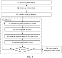
- the present disclosure corresponds to a method that is illustrated in a flowchart in Figure 4 .
- the method relates to processing a transceiver signal 115 detected by a transceiver 110.
- the method comprises obtaining S1 a processed signal from the transceiver signal 115, the processed signal comprising frames 200, 300 corresponding to respective time intervals t1, t2, t3, t4, wherein the frames comprise bins 210, 310 configured according to a quantized resolution dr of the transceiver signal 115.
- the method further comprises obtaining S2 data related to a relative motion of the transceiver 110 with respect to an object 150 in a field of view of the transceiver 110 during a time interval t1, t2, t3, t4 and initializing S3 a residual distance to zero.
- the method further comprises determining S4 a shift distance ds1, ds3 corresponding to a sum of the residual distance and a distance value d1, d2 corresponding to a relative motion of the transceiver 110 with respect to said object 150 in the respective time interval t1, t2, t3, t4, rounding S5 the determined shift distance ds1, ds3 with respect to the distance resolution dr to a rounded shift distance.
- the method then comprises updating S6 the residual distance based on a difference between the determined shift distance ds1, ds3 and the rounded shift distance, and generating S7 an adjusted frame 304 by shifting the bins 310 of the frame by the rounded shift distance to account for relative transceiver motion with respect to said object 150 in the respective time interval.
- the method then comprises processing S8 the signal by integrating bin values 210, 310 over the adjusted frames 300.
- the signal is a radar signal detected by a radar transceiver 110, where the bins 210, 310 are configured according to a distance resolution dr of the radar signal 115.
- the distance resolution dr is proportional to a frequency span df of each bin 210, 310.
- the radar signal is a frequency modulated continuous wave (FMCW) radar signal.
- FMCW frequency modulated continuous wave
- a frame corresponds to a Fourier transform or Fast Fourier Transform (FFT) vector.
- FFT Fast Fourier Transform
- the data related to a relative motion of the transceiver 110 is obtained from a Doppler shift of the received signal.
- the data related to a motion of the transceiver 110 during the time interval t1-t4 comprises data related to a motion of the transceiver 110 in an absolute coordinate frame.
- the rounding comprises either:
- obtaining data related to a motion of the transceiver 110 in a vehicle 100 comprises obtaining data related to an acceleration of the vehicle 100 in a time interval.
- obtaining data related to a motion of the transceiver 110 comprises filtering the data to suppress noise in the data.
- the filtering comprises any of Kalman filtering, particle filtering, or Wiener filtering.
- obtaining data related to a motion of the transceiver 110 in a vehicle 100 comprises obtaining data related to a heading of the vehicle 100.
- FIG. 5 schematically illustrates a control unit 120 according to aspects of the present disclosure. It is appreciated that the above described methods and techniques may be realized in hardware. This hardware is then arranged to perform the methods, whereby the same advantages and effects are obtained as have been discussed above.
- Processing circuitry 510 is provided using any combination of one or more of a suitable central processing unit (CPU), multiprocessor, microcontroller, digital signal processor (DSP), etc., capable of executing software instructions stored in a computer program product, e.g. in the form of a storage medium 530.
- the processing circuitry 510 may further be provided as at least one application specific integrated circuit (ASIC), or field programmable gate array (FPGA).
- ASIC application specific integrated circuit
- FPGA field programmable gate array
- the processing circuitry 510 is configured to cause the classification unit to perform a set of operations, or steps.
- the storage medium 530 may store the set of operations
- the processing circuitry 510 may be configured to retrieve the set of operations from the storage medium 530 to cause the classification unit to perform the set of operations.
- the set of operations may be provided as a set of executable instructions.
- the processing circuitry 510 is thereby arranged to execute methods as herein disclosed.
- the storage medium 530 may also comprise persistent storage, which, for example, can be any single one or combination of magnetic memory, optical memory, solid state memory or even remotely mounted memory.
- the control unit 120 may further comprise a communications interface 520 for communications with at least one external device such as the transceiver 110.
- the communication interface 520 may comprise one or more transmitters and receivers, comprising analogue and digital components and a suitable number ports for wireline or wireless communication.
- the processing circuitry 510 controls the general operation of the unit, e.g. by sending data and control signals to the communication interface 520 and the storage medium 530, by receiving data and reports from the communication interface 520, and by retrieving data and instructions from the storage medium 530.
- Other components, as well as the related functionality, of the unit are omitted in order not to obscure the concepts presented herein.
- Figure 6 schematically illustrates a computer program product 600 comprising a computer program 610 according to the disclosure above, and a computer readable storage medium 620 on which the computer program is stored.
- the present disclosure relates to a control unit 120 for a vehicle 100, where the control unit 120 is arranged to process a transceiver signal 115 detected by a transceiver 110.
- the control unit 120 comprises a first obtaining module Sx1 configured to obtain a processed signal from the transceiver signal 115, the processed signal comprising frames 200, 300 corresponding to respective time intervals t1, t2, t3, t4, wherein the frames comprise bins 210, 310 configured according to a quantized resolution dr of the transceiver signal 115,
- the control unit 120 further comprises a second obtaining module Sx2 configured to obtain data related to a relative motion of the transceiver 110 with respect to an object 150 in a field of view of the transceiver 110 during a time interval t1, t2, t3, t4, and an initialization module Sx3 configured to initialize a residual distance to zero.
- the control unit 120 is arranged to, for each frame 200, 300 and each respective time interval t1, t2, t3, t4, determine, by a determining module Sx4 a shift distance ds1, ds3 corresponding to a sum of the residual distance and a distance value d1, d2 corresponding to a relative motion of the transceiver 110 with respect to said object in the respective time interval t1, t2, t3, t4 and to round, by a rounding module Sx5, the determined shift distance ds1, ds) with respect to the distance resolution dr to a rounded shift distance.
- the control unit 120 is then arranged to update, by an updating module Sx6, the residual distance based on a difference between the determined shift distance ds1, ds3 and the rounded shift distance, and to generate, by a generating module Sx7, an adjusted frame 340 by shifting the bins of the frame by the rounded shift distance to account for relative transceiver motion with respect to said object 150 in the respective time interval.
- the control unit 120 further comprises a processing module Sx8 configured to process the signal by integrating the bin values over the adjusted frames.
- the signal is a radar signal detected by a radar transceiver 110, where the bins 210, 310 are configured according to a distance resolution dr of the radar signal 115.
- the distance resolution dr is proportional to a frequency span df of each bin 210, 310.
- the present disclosure is not limited to the examples described above, but may vary within the scope of the appended claims.
- the method can be applied to any suitable type of environment sensor, and in any kind of vehicle.
Landscapes
- Engineering & Computer Science (AREA)
- Radar, Positioning & Navigation (AREA)
- Remote Sensing (AREA)
- Physics & Mathematics (AREA)
- Computer Networks & Wireless Communication (AREA)
- General Physics & Mathematics (AREA)
- Electromagnetism (AREA)
- Acoustics & Sound (AREA)
- Radar Systems Or Details Thereof (AREA)
Abstract
Description
- The present disclosure relates to a method for processing a signal detected by a transceiver, where the signal comprises frames corresponding to respective time intervals. The frames comprise bins configured according to a quantized resolution of the signal.
- Many vehicle radar systems comprise radar transceivers that are arranged for generating radar signals that are transmitted, reflected and received by means of appropriate antennas comprised in the radar system. The radar signals may for example be in the form of FMCW (Frequency Modulated Continuous Wave) signals.
- Sometimes it is desired to enhance the integration gain, or signal to noise ratio, with maintained resolution of a radar transceiver in order to be able to distinguish a target, for example in a noisy environment, if the target provide weak detections, and if the target should be analyzed further, for example if the type of target should be determined.
- This can be done by correcting for the motion of the radar transceiver, and it is an object of the present disclosure to provide such a correction in an efficient manner with reduced computational complexity.
- This object is achieved by a method for processing a transceiver signal detected by a transceiver, the method comprising obtaining a processed signal from the transceiver signal, the processed signal comprising frames corresponding to respective time intervals. The frames comprise bins configured according to a quantized resolution of the transceiver signal. The method further comprises obtaining data related to a relative motion of the transceiver with respect to an object in a field of view of the transceiver during a time interval, and initializing a residual distance to zero.
- For each frame and each respective time interval the method further comprises determining a shift distance corresponding to a sum of the residual distance and a distance value corresponding to a relative motion of the transceiver with respect to said object in the respective time interval, rounding the determined shift distance with respect to the distance resolution to a rounded shift distance. Furthermore, the method then comprises updating the residual distance based on a difference between the determined shift distance and the rounded shift distance and generating an adjusted frame by shifting the bins of the frame by the rounded shift distance to account for relative transceiver motion with respect to said object in the respective time interval. The method then comprises processing the signal by integrating bin values over the adjusted frames.
- This enables correction for radar transceiver motion in a more efficient manner than previously known, with reduced computational complexity.
- The in turn enables enhancement of integration gain, or signal to noise ratio, with maintained resolution of a radar transceiver in order to be able to distinguish a target, for example in a noisy environment, if the target provide weak detections, and if the target should be analyzed further, for example if the type of target should be determined.
- According to some aspects, the signal is a radar signal detected by a radar transceiver, where the bins are configured according to a distance resolution of the radar signal. The distance resolution is proportional to a frequency span of each bin.
- According to some aspects, the radar signal is a frequency modulated continuous wave (FMCW) radar signal.
- According to some aspects, a frame corresponds to a Fourier transform or Fast Fourier Transform (FFT) vector.
- The method can thus be applied for a radar system.
- According to some aspects, the data related to a relative motion of the transceiver is obtained from a Doppler shift of the received signal.
- According to some aspects, the data related to a motion of the transceiver during the time interval comprises data related to a motion of the transceiver in an absolute coordinate frame.
- According to some aspects, the rounding comprises rounding either:
- up to the nearest upper integer multiple of the distance resolution,
- down to the nearest lower integer multiple of the distance resolution, or
- to the nearest integer multiple of the distance resolution.
- In this way, any suitable type of rounding can be used.
- According to some aspects, obtaining data related to a motion of the transceiver in a vehicle comprises obtaining data related to an acceleration of the vehicle in a time interval.
- In this manner, possible acceleration can also be taken into account.
- According to some aspects, obtaining data related to a motion of the transceiver comprises filtering the data to suppress noise in the data.
- According to some aspects, the filtering comprises any of Kalman filtering, particle filtering, or Wiener filtering.
- The filtering can thus be performed in many known ways.
- According to some aspects, obtaining data related to a motion of the transceiver in a vehicle comprises obtaining data related to a heading of the vehicle.
- In this way, the heading of the vehicle can be taken into account.
- The present disclosure also relates to a corresponding control unit that is associated with the advantages according to the above.
- The present disclosure will now be described in detail with reference to the appended drawings, where:
-
Figure 1 shows a schematic top view of a vehicle with a radar transceiver; -
Figure 2 schematically illustrates a radar signal frame; -
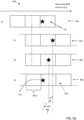
Figure 3A-3B illustrate radar signal frames over time intervals; -
Figure 4 is a flow chart illustrating methods; -
Figure 5 schematically illustrates a control unit; -
Figure 6 shows an example computer program product; and -
Figure 7 schematically illustrates a control unit; - Aspects of the present disclosure will now be described more fully hereinafter with reference to the accompanying drawings. The different devices, systems, computer programs and methods disclosed herein can, however, be realized in many different forms and should not be construed as being limited to the aspects set forth herein. Like numbers in the drawings refer to like elements throughout.
- The terminology used herein is for describing aspects of the disclosure only and is not intended to limit the invention. As used herein, the singular forms "a", "an" and "the" are intended to include the plural forms as well, unless the context clearly indicates otherwise.
-
Figure 1 shows avehicle 100 that comprises aradar system 140 which in turn comprises aradar transceiver 110 and acontrol unit 120. Theradar transceiver 110 is according to some aspects constituted by an FMCW (Frequency Modulated Continuous Wave) transceiver adapted for transmitting frequency modulated signals and receiving corresponding reflected signals in a previously known manner. In this example a signal has been reflected by anobject 150 within a field of view of thetransceiver 110 during a time interval constitutes atransceiver signal 115 that has been detected by atransceiver 110, where thetransceiver 110 has a relative motion with respect to theobject 150. Thetransceiver signal 115 is mixed with the transmitted signal such that a difference signal that constitutes an IF (Intermediate Frequency) signal is obtained and filtered. - By means of, for example, FFT (Fast Fourier Transform) the IF signal is transformed to a processed signal that, as shown in
Figure 2 , comprisesframes 200, where eachframe 200 corresponds to a respective time interval dt and according to some aspects is constituted by an FFT vector. Eachframe 200 comprisebins 210 configured according to a distance resolution dr of the processed signal, where the distance resolution dr is proportional to a corresponding frequency span df of each bin in a known manner. In eachbin 210, there is asignal detection 220 that has a complex value, i.e. a magnitude and a phase angle. - As shown in
Figure 3A , there is a plurality offrames 300, eachframe bins 310. Asignal detection 320 corresponding to theobject 150 is shown in acertain bin 311, for a first time interval t1, a second time interval t2 and a third time interval t3. A constant phase angle for thesignal detection 320 between the time intervals t1, t2, t3 corresponds to an absence of relative motion of thetransceiver 110 with respect to theobject 150, while a changing phase for thesignal detection 320 between the time intervals t1, t2, t3 corresponds to a certain relative motion of thetransceiver 110 with respect to theobject 150. A further FFT of the bin values for different time intervals reveals the relative motion such that a range-Doppler matrix can be obtained in a previously known manner. - In this example, there is a relative motion of the
transceiver 110 with respect to theobject 150 during the three time intervals t1, t2, t3, which is conceptually illustrated as thecorresponding signal detection 320 moves within itsbin 311 as shown for three correspondingconsecutive frames line 330 that runs through thesignal detection 320. Finally, thesignal detection 320 will leave its bin for a neighboring bin. - In order to compensate for error sources such as background noise, it is sometimes desirable to integrate the
frames signal detections 320 over time such that thesignal detection 320 is easier to distinguish. If there is a relative motion of thetransceiver 110 with respect to theobject 150, and thecorresponding signal detection 320 leaves its bin for a neighboring bin, this will affect the integration negatively, thesignal detection 320 being smeared over several bins during the integration. - It is therefore desired to integrate and at the same time compensate for the relative motion. According to the present disclosure, as illustrated for a fourth time t4 in
Figure 3A , when thesignal detection 320 leaves its bin for a neighboringbin 340 in acorresponding frame 304, the bins are shifted such that thesignal detection 320 appears at its original bin. - How this is accomplished will now be described more in detail with reference to
Figure 3B that shows an enlarged part ofFigure 3A around thesignal detection 320. A residual distance is initially set to zero at a first time interval t1. At a following second time interval t2, at a first cycle, a first shift distance ds1 is determined corresponding to a sum of the residual distance, which here is initially zero, and a first distance value d1 corresponding to a relative motion of thetransceiver 110 with respect to saidobject 150 in the second time interval t2. The first shift distance ds1 then here equals the first distance value ds1. - Next, the first shift distance ds1 is rounded with respect to the distance resolution dr to a first rounded shift distance. According to some aspects the rounding comprises rounding to the nearest integer multiple of the distance resolution dr. Here, the first shift distance ds1 falling below half the distance resolution dr, the rounding is zero and the rounded shift distance is zero.
- Then the residual distance is updated based on a difference between the determined first shift distance ds1 and the rounded shift distance which is zero, i.e. the residual distance equals the first shift distance ds1. After that an adjusted frame is generated by shifting the
bins 310 of the frame by the rounded shift distance to account for relative transceiver motion with respect to said object in the respective time interval, in this case there is no shift since the rounded shift distance is zero. - At a following cycle, at a following third time interval t3, a second shift distance ds2 is determined corresponding to a sum of the residual distance, which here equals the first shift distance ds1, and a second distance value d2 corresponding to a relative motion of the
transceiver 110 with respect to saidobject 150 in the second time interval t3. The second shift distance ds2 then here equals a sum of the first distance value d1 and the second distance value d2. - Next, the second shift distance ds2 is rounded with respect to the distance resolution dr to a second rounded shift distance. Here, the second shift distance ds2 exceeding half the distance resolution dr but still falling below the distance resolution dr, the rounding equals the distance resolution dr.
- Then the residual distance is updated based on a difference between the determined second shift distance ds2 and the rounded shift distance which is the distance resolution dr. After that, an adjusted frame is generated by shifting the
bins 310 of the frame by the rounded shift distance dr which is shown for a fourth time interval t4. Here, thesignal detection 320 has just moved to a neighboringbin 340. - The above procedure is repeated for all frames for which an integration is to be made. When all frames have been processed according to the above, the signal is further processed by integrating
bin values - In case there are more than one object of
interest - It is noted that by applying an FFT, as for generating Doppler values, an integration is implicitly performed. However, it is appreciated that the integrating can be performed in a number of different ways according to different implementation aspects of the technique. For instance, magnitudes of frame values can be summed. This integration is then independent of phase value in the different bins.
- A coherent integration can also be performed, i.e., summing complex values in the bins over time. Such a coherent integration may comprise adjusting phases to account for the relative velocity.
- According to some aspects, the adjusted frame is generated by shifting the
bins 310 of the frame by the rounded shift distance dr. - In the above, the present disclosure has been described for a
radar system 140 which in turn comprises aradar transceiver 110 and acontrol unit 120. Generally, the present disclosure can be applied to any kind of suitable environment detection system which comprises a transceiver adapted to detect a signal and a control unit. The detected signal comprises frames corresponding to respective time intervals t1, t2, t3, t4, where the frames comprise bins configured according to a quantized resolution of the signal. The type of signal and transceiver used is dependent on the kind of environment detection system, where according to some aspects a camera system is adapted to detect image signals and a Lidar system is adapted to detect light signals. - Generally, the present disclosure corresponds to a method that is illustrated in a flowchart in
Figure 4 . The method relates to processing atransceiver signal 115 detected by atransceiver 110. The method comprises obtaining S1 a processed signal from thetransceiver signal 115, the processedsignal comprising frames bins transceiver signal 115. The method further comprises obtaining S2 data related to a relative motion of thetransceiver 110 with respect to anobject 150 in a field of view of thetransceiver 110 during a time interval t1, t2, t3, t4 and initializing S3 a residual distance to zero. - For each
frame transceiver 110 with respect to saidobject 150 in the respective time interval t1, t2, t3, t4, rounding S5 the determined shift distance ds1, ds3 with respect to the distance resolution dr to a rounded shift distance. Furthermore, the method then comprises updating S6 the residual distance based on a difference between the determined shift distance ds1, ds3 and the rounded shift distance, and generating S7 an adjustedframe 304 by shifting thebins 310 of the frame by the rounded shift distance to account for relative transceiver motion with respect to saidobject 150 in the respective time interval. The method then comprises processing S8 the signal by integratingbin values - According to some aspects, as discussed above, the signal is a radar signal detected by a
radar transceiver 110, where thebins radar signal 115. The distance resolution dr is proportional to a frequency span df of each bin 210, 310. - According to some aspects, the radar signal is a frequency modulated continuous wave (FMCW) radar signal.
- According to some aspects, a frame corresponds to a Fourier transform or Fast Fourier Transform (FFT) vector.
- According to some aspects, the data related to a relative motion of the
transceiver 110 is obtained from a Doppler shift of the received signal. - According to some aspects, the data related to a motion of the
transceiver 110 during the time interval t1-t4 comprises data related to a motion of thetransceiver 110 in an absolute coordinate frame. - According to some aspects, the rounding comprises either:
- rounding up to the nearest upper integer multiple of the distance resolution dr;
- rounding down to the nearest lower integer multiple of the distance resolution dr; or
- rounding to the nearest integer multiple of the distance resolution dr.
- According to some aspects, obtaining data related to a motion of the
transceiver 110 in avehicle 100 comprises obtaining data related to an acceleration of thevehicle 100 in a time interval. - According to some aspects, obtaining data related to a motion of the
transceiver 110 comprises filtering the data to suppress noise in the data. According to some aspects, the filtering comprises any of Kalman filtering, particle filtering, or Wiener filtering. - According to some aspects, obtaining data related to a motion of the
transceiver 110 in avehicle 100 comprises obtaining data related to a heading of thevehicle 100. -
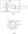
Figure 5 schematically illustrates acontrol unit 120 according to aspects of the present disclosure. It is appreciated that the above described methods and techniques may be realized in hardware. This hardware is then arranged to perform the methods, whereby the same advantages and effects are obtained as have been discussed above. -
Processing circuitry 510 is provided using any combination of one or more of a suitable central processing unit (CPU), multiprocessor, microcontroller, digital signal processor (DSP), etc., capable of executing software instructions stored in a computer program product, e.g. in the form of astorage medium 530. Theprocessing circuitry 510 may further be provided as at least one application specific integrated circuit (ASIC), or field programmable gate array (FPGA). - Particularly, the
processing circuitry 510 is configured to cause the classification unit to perform a set of operations, or steps. For example, thestorage medium 530 may store the set of operations, and theprocessing circuitry 510 may be configured to retrieve the set of operations from thestorage medium 530 to cause the classification unit to perform the set of operations. The set of operations may be provided as a set of executable instructions. Thus, theprocessing circuitry 510 is thereby arranged to execute methods as herein disclosed. - The
storage medium 530 may also comprise persistent storage, which, for example, can be any single one or combination of magnetic memory, optical memory, solid state memory or even remotely mounted memory. - The
control unit 120 may further comprise acommunications interface 520 for communications with at least one external device such as thetransceiver 110. As such thecommunication interface 520 may comprise one or more transmitters and receivers, comprising analogue and digital components and a suitable number ports for wireline or wireless communication. - The
processing circuitry 510 controls the general operation of the unit, e.g. by sending data and control signals to thecommunication interface 520 and thestorage medium 530, by receiving data and reports from thecommunication interface 520, and by retrieving data and instructions from thestorage medium 530. Other components, as well as the related functionality, of the unit are omitted in order not to obscure the concepts presented herein. -
Figure 6 schematically illustrates acomputer program product 600 comprising acomputer program 610 according to the disclosure above, and a computerreadable storage medium 620 on which the computer program is stored. - With reference to
Figure 7 , the present disclosure relates to acontrol unit 120 for avehicle 100, where thecontrol unit 120 is arranged to process atransceiver signal 115 detected by atransceiver 110. Thecontrol unit 120 comprises a first obtaining module Sx1 configured to obtain a processed signal from thetransceiver signal 115, the processedsignal comprising frames bins transceiver signal 115, Thecontrol unit 120 further comprises a second obtaining module Sx2 configured to obtain data related to a relative motion of thetransceiver 110 with respect to anobject 150 in a field of view of thetransceiver 110 during a time interval t1, t2, t3, t4, and an initialization module Sx3 configured to initialize a residual distance to zero. - The
control unit 120 is arranged to, for eachframe transceiver 110 with respect to said object in the respective time interval t1, t2, t3, t4 and to round, by a rounding module Sx5, the determined shift distance ds1, ds) with respect to the distance resolution dr to a rounded shift distance. - The
control unit 120 is then arranged to update, by an updating module Sx6, the residual distance based on a difference between the determined shift distance ds1, ds3 and the rounded shift distance, and to generate, by a generating module Sx7, an adjustedframe 340 by shifting the bins of the frame by the rounded shift distance to account for relative transceiver motion with respect to saidobject 150 in the respective time interval. - The
control unit 120 further comprises a processing module Sx8 configured to process the signal by integrating the bin values over the adjusted frames. - According to some aspects, the signal is a radar signal detected by a
radar transceiver 110, where thebins radar signal 115. The distance resolution dr is proportional to a frequency span df of each bin 210, 310. - The present disclosure is not limited to the examples described above, but may vary within the scope of the appended claims. For example, the method can be applied to any suitable type of environment sensor, and in any kind of vehicle.
Claims (15)
- A method for processing a transceiver signal (115) detected by a transceiver (110), the method comprising;
obtaining (S1) a processed signal from the transceiver signal (115), the processed signal comprising frames (200, 300) corresponding to respective time intervals (t1, t2, t3, t4), wherein the frames comprise bins (210, 310) configured according to a quantized resolution (dr) of the transceiver signal (115);
obtaining (S2) data related to a relative motion of the transceiver (110) with respect to an object (150) in a field of view of the transceiver (110) during a time interval (t1, t2, t3, t4);
initializing (S3) a residual distance to zero; and, for each frame (200, 300) and each respective time interval (t1, t2, t3, t4);
determining (S4) a shift distance (ds1, ds3) corresponding to a sum of the residual distance and a distance value (d1, d2) corresponding to a relative motion of the transceiver (110) with respect to said object (150) in the respective time interval (t1, t2, t3, t4);
rounding (S5) the determined shift distance (ds1, ds3) with respect to the distance resolution (dr) to a rounded shift distance;
updating (S6) the residual distance based on a difference between the determined shift distance (ds1, ds3) and the rounded shift distance;
generating (S7) an adjusted frame (304) by shifting the bins (310) of the frame by the rounded shift distance to account for relative transceiver motion with respect to said object (150) in the respective time interval; and
processing (S8) the signal by integrating bin values (210, 310) over the adjusted frames (300). - The method according to claim 1, wherein the signal is a radar signal detected by a radar transceiver (110), where the bins (210, 310) are configured according to a distance resolution (dr) of the radar signal (115), where the distance resolution (dr) is proportional to a frequency span (df) of each bin (210, 310) .
- The method according to claim 2, wherein the radar signal is a frequency modulated continuous wave, FMCW, radar signal.
- The method according to any previous claim, wherein a frame corresponds to a Fourier transform or Fast Fourier Transform, FFT, vector.
- The method according to any one of the previous claims, wherein the data related to a relative motion of the transceiver (110) is obtained from a Doppler shift of the received signal.
- The method according to any one of the claims 1-4, wherein the data related to a motion of the transceiver (110) during the time interval (t1, t2, t3, t4) comprises data related to a motion of the transceiver (110) in an absolute coordinate frame.
- The method according to any previous claim, wherein the rounding comprises rounding up to the nearest upper integer multiple of the distance resolution (dr).
- The method according to any previous claim, wherein the rounding comprises rounding down to the nearest lower integer multiple of the distance resolution (dr).
- The method according to any previous claim, wherein the rounding comprises rounding to the nearest integer multiple of the distance resolution (dr).
- The method according to any previous claim, wherein obtaining data related to a motion of the transceiver (110) in a vehicle (100) comprises obtaining data related to an acceleration of the vehicle (100) in a time interval.
- The method according to any previous claim, wherein obtaining data related to a motion of the transceiver (110) comprises filtering the data to suppress noise in the data.
- The method according to claim 10, wherein the filtering comprises any of Kalman filtering, particle filtering, or Wiener filtering.
- The method according to any previous claim, wherein obtaining data related to a motion of the transceiver (110) in a vehicle (100) comprises obtaining data related to a heading of the vehicle (100).
- A control unit (120) for a vehicle (100) where the control unit (120) is arranged to process a transceiver signal (115) detected by a transceiver (110), where the control unit (120) comprises:a first obtaining module (Sx1) configured to obtain a processed signal from the transceiver signal (115), the processed signal comprising frames (200, 300) corresponding to respective time intervals (t1, t2, t3, t4), wherein the frames comprise bins (210, 310) configured according to a quantized resolution (dr) of the transceiver signal (115);a second obtaining module (Sx2) configured to obtain data related to a relative motion of the transceiver (110) with respect to an object (150) in a field of view of the transceiver (110) during a time interval (t1, t2, t3, t4); characterized in that the control unit (120) further comprises:an initialization module (Sx3) configured to initialize a residual distance to zero;wherein the control unit (120) is arranged to, for each frame (200, 300) and each respective time interval (t1, t2, t3, t4);determine, by a determining module (Sx4) a shift distance (ds1, ds3) corresponding to a sum of the residual distance and a distance value (d1, d2) corresponding to a relative motion of the transceiver (110) with respect to said object in the respective time interval (t1, t2, t3, t4);round, by a rounding module (Sx5), the determined shift distance (ds1, ds3) with respect to the distance resolution (dr) to a rounded shift distance;update, by an updating module (Sx6), the residual distance based on a difference between the determined shift distance (ds1, ds3) and the rounded shift distance; and togenerate, by a generating module (Sx7), an adjusted frame (340) by shifting the bins of the frame by the rounded shift distance to account for relative transceiver motion with respect to said object (150) in the respective time interval;the control unit (120) further comprising a processing module (Sx8) configured to process the signal by integrating the bin values over the adjusted frames.
- The control unit (120) according to claim 14, wherein the signal is a radar signal detected by a radar transceiver (110), where the bins (210, 310) are configured according to a distance resolution (dr) of the radar signal (115), where the distance resolution (dr) is proportional to a frequency span (df) of each bin (210, 310).
Priority Applications (4)
| Application Number | Priority Date | Filing Date | Title |
|---|---|---|---|
| EP18206774.4A EP3654054B1 (en) | 2018-11-16 | 2018-11-16 | Signal integration with transceiver motion compensation |
| PCT/EP2019/080191 WO2020099175A1 (en) | 2018-11-16 | 2019-11-05 | Signal integration with transceiver motion compensation |
| CN201980070233.XA CN112912754B (en) | 2018-11-16 | 2019-11-05 | Signal integration with transceiver motion compensation |
| US17/293,137 US11914030B2 (en) | 2018-11-16 | 2019-11-05 | Signal integration with transceiver motion compensation |
Applications Claiming Priority (1)
| Application Number | Priority Date | Filing Date | Title |
|---|---|---|---|
| EP18206774.4A EP3654054B1 (en) | 2018-11-16 | 2018-11-16 | Signal integration with transceiver motion compensation |
Publications (2)
| Publication Number | Publication Date |
|---|---|
| EP3654054A1 true EP3654054A1 (en) | 2020-05-20 |
| EP3654054B1 EP3654054B1 (en) | 2021-06-30 |
Family
ID=64362351
Family Applications (1)
| Application Number | Title | Priority Date | Filing Date |
|---|---|---|---|
| EP18206774.4A Active EP3654054B1 (en) | 2018-11-16 | 2018-11-16 | Signal integration with transceiver motion compensation |
Country Status (4)
| Country | Link |
|---|---|
| US (1) | US11914030B2 (en) |
| EP (1) | EP3654054B1 (en) |
| CN (1) | CN112912754B (en) |
| WO (1) | WO2020099175A1 (en) |
Families Citing this family (1)
| Publication number | Priority date | Publication date | Assignee | Title |
|---|---|---|---|---|
| JP7173342B2 (en) * | 2019-06-28 | 2022-11-16 | 日本電気株式会社 | Radar device, imaging method and imaging program |
Citations (1)
| Publication number | Priority date | Publication date | Assignee | Title |
|---|---|---|---|---|
| US20170146638A1 (en) * | 2014-05-13 | 2017-05-25 | Mitsubishi Electric Corporation | Radar device |
Family Cites Families (7)
| Publication number | Priority date | Publication date | Assignee | Title |
|---|---|---|---|---|
| US4617567A (en) * | 1984-09-28 | 1986-10-14 | The Boeing Company | Automatic motion compensation for residual motion in a synthetic aperture radar system |
| US20150301167A1 (en) * | 2009-12-18 | 2015-10-22 | Christopher Gary Sentelle | Detection of movable objects |
| WO2012020439A1 (en) * | 2010-08-11 | 2012-02-16 | Selex Galileo S.P.A. | Multi-grazing isar imaging method and system providing isar side-view images with improved cross-range resolution |
| CN106507958B (en) * | 2012-05-09 | 2014-08-27 | 中国科学院电子学研究所 | The method of the real-time coherent accumulation of external illuminators-based radar signal |
| EP3211445B1 (en) * | 2016-02-29 | 2019-06-12 | Nxp B.V. | Radar system |
| US10775489B2 (en) * | 2016-12-15 | 2020-09-15 | Texas Instruments Incorporated | Maximum measurable velocity in frequency modulated continuous wave (FMCW) radar |
| CN108107430B (en) * | 2017-11-09 | 2023-03-03 | 北京理工大学 | A Ship Target ISAR Imaging Method Based on Fractional Fourier Transform |
-
2018
- 2018-11-16 EP EP18206774.4A patent/EP3654054B1/en active Active
-
2019
- 2019-11-05 US US17/293,137 patent/US11914030B2/en active Active
- 2019-11-05 WO PCT/EP2019/080191 patent/WO2020099175A1/en not_active Ceased
- 2019-11-05 CN CN201980070233.XA patent/CN112912754B/en active Active
Patent Citations (1)
| Publication number | Priority date | Publication date | Assignee | Title |
|---|---|---|---|---|
| US20170146638A1 (en) * | 2014-05-13 | 2017-05-25 | Mitsubishi Electric Corporation | Radar device |
Non-Patent Citations (2)
| Title |
|---|
| HAIKUN LUO ET AL: "A segmentation motion compensation-based longterm integration method for DSSS signal", SIGNAL PROCESSING (ICSP), 2012 IEEE 11TH INTERNATIONAL CONFERENCE ON, IEEE, 21 October 2012 (2012-10-21), pages 1287 - 1290, XP032353473, ISBN: 978-1-4673-2196-9, DOI: 10.1109/ICOSP.2012.6491811 * |
| SHUNSHENG ZHANG ET AL: "Multiple targets' detection in terms of Keystone transform at the low SNR level", INFORMATION AND AUTOMATION, 2008. ICIA 2008. INTERNATIONAL CONFERENCE ON, IEEE, PISCATAWAY, NJ, USA, 20 June 2008 (2008-06-20), pages 1 - 4, XP031313147, ISBN: 978-1-4244-2183-1 * |
Also Published As
| Publication number | Publication date |
|---|---|
| CN112912754A (en) | 2021-06-04 |
| US11914030B2 (en) | 2024-02-27 |
| US20220011427A1 (en) | 2022-01-13 |
| EP3654054B1 (en) | 2021-06-30 |
| WO2020099175A1 (en) | 2020-05-22 |
| CN112912754B (en) | 2024-07-05 |
Similar Documents
| Publication | Publication Date | Title |
|---|---|---|
| US11243304B2 (en) | Systems and methods for interpolated virtual aperature radar tracking | |
| CN114144697B (en) | System and method for interpolated virtual aperture radar tracking | |
| US10976412B2 (en) | Deep learning for super resolution in a radar system | |
| JP7117064B2 (en) | radar equipment, radar system | |
| KR102819557B1 (en) | Angular resolution of targets using separate radar receivers | |
| KR102842139B1 (en) | Method and apparatus for detecting object based on radar signal | |
| US9329264B2 (en) | SAR image formation | |
| US11092686B2 (en) | Method, apparatus and device for doppler compensation in a time switched MIMO radar system | |
| US20070194982A1 (en) | Antenna signal processing apparatus | |
| KR20210082946A (en) | Method and device to process radar signal | |
| KR20200144862A (en) | Method and device to improve resolution of radar | |
| CN110806580B (en) | Vibration mitigation in radar systems on mobile platforms | |
| US20150035697A1 (en) | Radar calibration system for vehicles | |
| US20180356508A1 (en) | A vehicle radar system arranged for determining an unoccupied domain | |
| WO2005066649A2 (en) | Radar receiver motion compensation system and method | |
| CN103630902B (en) | A kind of phase correction formation method for timesharing receiving array SAR | |
| EP3460515B1 (en) | Mapping for autonomous robotic devices | |
| EP2250517A1 (en) | Radar imaging of buildings using model-based focusing and data-based focusing | |
| US20190086512A1 (en) | Method and apparatus for vehicular radar calibration | |
| EP3477334A1 (en) | Automatic radar sensor calibration | |
| AU2018383433B2 (en) | System and method for synthetic aperture radar image formation | |
| CN114720969A (en) | Method and system for compressing radar data | |
| CN111025256A (en) | Method and system for detecting weak vital sign signal of airborne radar | |
| US11914030B2 (en) | Signal integration with transceiver motion compensation | |
| US11709259B2 (en) | Method for operating a sensor of a motor vehicle |
Legal Events
| Date | Code | Title | Description |
|---|---|---|---|
| PUAI | Public reference made under article 153(3) epc to a published international application that has entered the european phase |
Free format text: ORIGINAL CODE: 0009012 |
|
| STAA | Information on the status of an ep patent application or granted ep patent |
Free format text: STATUS: THE APPLICATION HAS BEEN PUBLISHED |
|
| AK | Designated contracting states |
Kind code of ref document: A1 Designated state(s): AL AT BE BG CH CY CZ DE DK EE ES FI FR GB GR HR HU IE IS IT LI LT LU LV MC MK MT NL NO PL PT RO RS SE SI SK SM TR |
|
| AX | Request for extension of the european patent |
Extension state: BA ME |
|
| STAA | Information on the status of an ep patent application or granted ep patent |
Free format text: STATUS: REQUEST FOR EXAMINATION WAS MADE |
|
| 17P | Request for examination filed |
Effective date: 20201117 |
|
| RBV | Designated contracting states (corrected) |
Designated state(s): AL AT BE BG CH CY CZ DE DK EE ES FI FR GB GR HR HU IE IS IT LI LT LU LV MC MK MT NL NO PL PT RO RS SE SI SK SM TR |
|
| RIC1 | Information provided on ipc code assigned before grant |
Ipc: G01S 13/524 20060101ALI20201208BHEP Ipc: G01S 7/292 20060101AFI20201208BHEP Ipc: G01S 7/35 20060101ALI20201208BHEP Ipc: G01S 7/493 20060101ALI20201208BHEP Ipc: G01S 17/50 20060101ALI20201208BHEP Ipc: G01S 13/50 20060101ALI20201208BHEP Ipc: G01S 13/58 20060101ALI20201208BHEP Ipc: G01S 13/931 20200101ALI20201208BHEP Ipc: G01S 7/487 20060101ALI20201208BHEP Ipc: G01S 15/50 20060101ALI20201208BHEP Ipc: G01S 7/536 20060101ALI20201208BHEP Ipc: G01S 7/527 20060101ALI20201208BHEP Ipc: G01S 15/58 20060101ALI20201208BHEP |
|
| GRAP | Despatch of communication of intention to grant a patent |
Free format text: ORIGINAL CODE: EPIDOSNIGR1 |
|
| STAA | Information on the status of an ep patent application or granted ep patent |
Free format text: STATUS: GRANT OF PATENT IS INTENDED |
|
| INTG | Intention to grant announced |
Effective date: 20210125 |
|
| GRAS | Grant fee paid |
Free format text: ORIGINAL CODE: EPIDOSNIGR3 |
|
| GRAA | (expected) grant |
Free format text: ORIGINAL CODE: 0009210 |
|
| STAA | Information on the status of an ep patent application or granted ep patent |
Free format text: STATUS: THE PATENT HAS BEEN GRANTED |
|
| AK | Designated contracting states |
Kind code of ref document: B1 Designated state(s): AL AT BE BG CH CY CZ DE DK EE ES FI FR GB GR HR HU IE IS IT LI LT LU LV MC MK MT NL NO PL PT RO RS SE SI SK SM TR |
|
| REG | Reference to a national code |
Ref country code: CH Ref legal event code: EP |
|
| REG | Reference to a national code |
Ref country code: AT Ref legal event code: REF Ref document number: 1406833 Country of ref document: AT Kind code of ref document: T Effective date: 20210715 |
|
| REG | Reference to a national code |
Ref country code: DE Ref legal event code: R096 Ref document number: 602018019285 Country of ref document: DE |
|
| REG | Reference to a national code |
Ref country code: IE Ref legal event code: FG4D |
|
| REG | Reference to a national code |
Ref country code: LT Ref legal event code: MG9D |
|
| PG25 | Lapsed in a contracting state [announced via postgrant information from national office to epo] |
Ref country code: BG Free format text: LAPSE BECAUSE OF FAILURE TO SUBMIT A TRANSLATION OF THE DESCRIPTION OR TO PAY THE FEE WITHIN THE PRESCRIBED TIME-LIMIT Effective date: 20210930 Ref country code: FI Free format text: LAPSE BECAUSE OF FAILURE TO SUBMIT A TRANSLATION OF THE DESCRIPTION OR TO PAY THE FEE WITHIN THE PRESCRIBED TIME-LIMIT Effective date: 20210630 Ref country code: HR Free format text: LAPSE BECAUSE OF FAILURE TO SUBMIT A TRANSLATION OF THE DESCRIPTION OR TO PAY THE FEE WITHIN THE PRESCRIBED TIME-LIMIT Effective date: 20210630 |
|
| REG | Reference to a national code |
Ref country code: NL Ref legal event code: MP Effective date: 20210630 |
|
| REG | Reference to a national code |
Ref country code: AT Ref legal event code: MK05 Ref document number: 1406833 Country of ref document: AT Kind code of ref document: T Effective date: 20210630 |
|
| PG25 | Lapsed in a contracting state [announced via postgrant information from national office to epo] |
Ref country code: GR Free format text: LAPSE BECAUSE OF FAILURE TO SUBMIT A TRANSLATION OF THE DESCRIPTION OR TO PAY THE FEE WITHIN THE PRESCRIBED TIME-LIMIT Effective date: 20211001 Ref country code: LV Free format text: LAPSE BECAUSE OF FAILURE TO SUBMIT A TRANSLATION OF THE DESCRIPTION OR TO PAY THE FEE WITHIN THE PRESCRIBED TIME-LIMIT Effective date: 20210630 Ref country code: NO Free format text: LAPSE BECAUSE OF FAILURE TO SUBMIT A TRANSLATION OF THE DESCRIPTION OR TO PAY THE FEE WITHIN THE PRESCRIBED TIME-LIMIT Effective date: 20210930 Ref country code: SE Free format text: LAPSE BECAUSE OF FAILURE TO SUBMIT A TRANSLATION OF THE DESCRIPTION OR TO PAY THE FEE WITHIN THE PRESCRIBED TIME-LIMIT Effective date: 20210630 Ref country code: RS Free format text: LAPSE BECAUSE OF FAILURE TO SUBMIT A TRANSLATION OF THE DESCRIPTION OR TO PAY THE FEE WITHIN THE PRESCRIBED TIME-LIMIT Effective date: 20210630 |
|
| PG25 | Lapsed in a contracting state [announced via postgrant information from national office to epo] |
Ref country code: EE Free format text: LAPSE BECAUSE OF FAILURE TO SUBMIT A TRANSLATION OF THE DESCRIPTION OR TO PAY THE FEE WITHIN THE PRESCRIBED TIME-LIMIT Effective date: 20210630 Ref country code: ES Free format text: LAPSE BECAUSE OF FAILURE TO SUBMIT A TRANSLATION OF THE DESCRIPTION OR TO PAY THE FEE WITHIN THE PRESCRIBED TIME-LIMIT Effective date: 20210630 Ref country code: SM Free format text: LAPSE BECAUSE OF FAILURE TO SUBMIT A TRANSLATION OF THE DESCRIPTION OR TO PAY THE FEE WITHIN THE PRESCRIBED TIME-LIMIT Effective date: 20210630 Ref country code: SK Free format text: LAPSE BECAUSE OF FAILURE TO SUBMIT A TRANSLATION OF THE DESCRIPTION OR TO PAY THE FEE WITHIN THE PRESCRIBED TIME-LIMIT Effective date: 20210630 Ref country code: CZ Free format text: LAPSE BECAUSE OF FAILURE TO SUBMIT A TRANSLATION OF THE DESCRIPTION OR TO PAY THE FEE WITHIN THE PRESCRIBED TIME-LIMIT Effective date: 20210630 Ref country code: AT Free format text: LAPSE BECAUSE OF FAILURE TO SUBMIT A TRANSLATION OF THE DESCRIPTION OR TO PAY THE FEE WITHIN THE PRESCRIBED TIME-LIMIT Effective date: 20210630 Ref country code: PT Free format text: LAPSE BECAUSE OF FAILURE TO SUBMIT A TRANSLATION OF THE DESCRIPTION OR TO PAY THE FEE WITHIN THE PRESCRIBED TIME-LIMIT Effective date: 20211102 Ref country code: RO Free format text: LAPSE BECAUSE OF FAILURE TO SUBMIT A TRANSLATION OF THE DESCRIPTION OR TO PAY THE FEE WITHIN THE PRESCRIBED TIME-LIMIT Effective date: 20210630 Ref country code: NL Free format text: LAPSE BECAUSE OF FAILURE TO SUBMIT A TRANSLATION OF THE DESCRIPTION OR TO PAY THE FEE WITHIN THE PRESCRIBED TIME-LIMIT Effective date: 20210630 |
|
| PG25 | Lapsed in a contracting state [announced via postgrant information from national office to epo] |
Ref country code: PL Free format text: LAPSE BECAUSE OF FAILURE TO SUBMIT A TRANSLATION OF THE DESCRIPTION OR TO PAY THE FEE WITHIN THE PRESCRIBED TIME-LIMIT Effective date: 20210630 |
|
| REG | Reference to a national code |
Ref country code: DE Ref legal event code: R097 Ref document number: 602018019285 Country of ref document: DE |
|
| PG25 | Lapsed in a contracting state [announced via postgrant information from national office to epo] |
Ref country code: DK Free format text: LAPSE BECAUSE OF FAILURE TO SUBMIT A TRANSLATION OF THE DESCRIPTION OR TO PAY THE FEE WITHIN THE PRESCRIBED TIME-LIMIT Effective date: 20210630 |
|
| PLBE | No opposition filed within time limit |
Free format text: ORIGINAL CODE: 0009261 |
|
| STAA | Information on the status of an ep patent application or granted ep patent |
Free format text: STATUS: NO OPPOSITION FILED WITHIN TIME LIMIT |
|
| PG25 | Lapsed in a contracting state [announced via postgrant information from national office to epo] |
Ref country code: AL Free format text: LAPSE BECAUSE OF FAILURE TO SUBMIT A TRANSLATION OF THE DESCRIPTION OR TO PAY THE FEE WITHIN THE PRESCRIBED TIME-LIMIT Effective date: 20210630 |
|
| 26N | No opposition filed |
Effective date: 20220331 |
|
| PG25 | Lapsed in a contracting state [announced via postgrant information from national office to epo] |
Ref country code: MC Free format text: LAPSE BECAUSE OF FAILURE TO SUBMIT A TRANSLATION OF THE DESCRIPTION OR TO PAY THE FEE WITHIN THE PRESCRIBED TIME-LIMIT Effective date: 20210630 |
|
| REG | Reference to a national code |
Ref country code: CH Ref legal event code: PL |
|
| PG25 | Lapsed in a contracting state [announced via postgrant information from national office to epo] |
Ref country code: LU Free format text: LAPSE BECAUSE OF NON-PAYMENT OF DUE FEES Effective date: 20211116 Ref country code: IT Free format text: LAPSE BECAUSE OF FAILURE TO SUBMIT A TRANSLATION OF THE DESCRIPTION OR TO PAY THE FEE WITHIN THE PRESCRIBED TIME-LIMIT Effective date: 20210630 Ref country code: BE Free format text: LAPSE BECAUSE OF NON-PAYMENT OF DUE FEES Effective date: 20211130 |
|
| REG | Reference to a national code |
Ref country code: BE Ref legal event code: MM Effective date: 20211130 |
|
| PG25 | Lapsed in a contracting state [announced via postgrant information from national office to epo] |
Ref country code: IE Free format text: LAPSE BECAUSE OF NON-PAYMENT OF DUE FEES Effective date: 20211116 |
|
| PG25 | Lapsed in a contracting state [announced via postgrant information from national office to epo] |
Ref country code: LT Free format text: LAPSE BECAUSE OF FAILURE TO SUBMIT A TRANSLATION OF THE DESCRIPTION OR TO PAY THE FEE WITHIN THE PRESCRIBED TIME-LIMIT Effective date: 20210630 |
|
| PG25 | Lapsed in a contracting state [announced via postgrant information from national office to epo] |
Ref country code: CY Free format text: LAPSE BECAUSE OF FAILURE TO SUBMIT A TRANSLATION OF THE DESCRIPTION OR TO PAY THE FEE WITHIN THE PRESCRIBED TIME-LIMIT Effective date: 20210630 |
|
| GBPC | Gb: european patent ceased through non-payment of renewal fee |
Effective date: 20221116 |
|
| PG25 | Lapsed in a contracting state [announced via postgrant information from national office to epo] |
Ref country code: LI Free format text: LAPSE BECAUSE OF NON-PAYMENT OF DUE FEES Effective date: 20220701 Ref country code: HU Free format text: LAPSE BECAUSE OF FAILURE TO SUBMIT A TRANSLATION OF THE DESCRIPTION OR TO PAY THE FEE WITHIN THE PRESCRIBED TIME-LIMIT; INVALID AB INITIO Effective date: 20181116 Ref country code: CH Free format text: LAPSE BECAUSE OF NON-PAYMENT OF DUE FEES Effective date: 20220701 |
|
| PG25 | Lapsed in a contracting state [announced via postgrant information from national office to epo] |
Ref country code: GB Free format text: LAPSE BECAUSE OF NON-PAYMENT OF DUE FEES Effective date: 20221116 |
|
| REG | Reference to a national code |
Ref country code: DE Ref legal event code: R081 Ref document number: 602018019285 Country of ref document: DE Owner name: MAGNA ELECTRONICS SWEDEN AB, SE Free format text: FORMER OWNER: VEONEER SWEDEN AB, VARGARDA, SE |
|
| PG25 | Lapsed in a contracting state [announced via postgrant information from national office to epo] |
Ref country code: MK Free format text: LAPSE BECAUSE OF FAILURE TO SUBMIT A TRANSLATION OF THE DESCRIPTION OR TO PAY THE FEE WITHIN THE PRESCRIBED TIME-LIMIT Effective date: 20210630 |
|
| PG25 | Lapsed in a contracting state [announced via postgrant information from national office to epo] |
Ref country code: MT Free format text: LAPSE BECAUSE OF FAILURE TO SUBMIT A TRANSLATION OF THE DESCRIPTION OR TO PAY THE FEE WITHIN THE PRESCRIBED TIME-LIMIT Effective date: 20210630 |
|
| PG25 | Lapsed in a contracting state [announced via postgrant information from national office to epo] |
Ref country code: TR Free format text: LAPSE BECAUSE OF FAILURE TO SUBMIT A TRANSLATION OF THE DESCRIPTION OR TO PAY THE FEE WITHIN THE PRESCRIBED TIME-LIMIT Effective date: 20210630 |
|
| PGFP | Annual fee paid to national office [announced via postgrant information from national office to epo] |
Ref country code: DE Payment date: 20251118 Year of fee payment: 8 |
|
| PGFP | Annual fee paid to national office [announced via postgrant information from national office to epo] |
Ref country code: FR Payment date: 20251125 Year of fee payment: 8 |