EP3654019A1 - Sample observation device and sample observation method - Google Patents
Sample observation device and sample observation method Download PDFInfo
- Publication number
- EP3654019A1 EP3654019A1 EP18831231.8A EP18831231A EP3654019A1 EP 3654019 A1 EP3654019 A1 EP 3654019A1 EP 18831231 A EP18831231 A EP 18831231A EP 3654019 A1 EP3654019 A1 EP 3654019A1
- Authority
- EP
- European Patent Office
- Prior art keywords
- sample
- image data
- light
- observation
- area
- Prior art date
- Legal status (The legal status is an assumption and is not a legal conclusion. Google has not performed a legal analysis and makes no representation as to the accuracy of the status listed.)
- Granted
Links
Images





Classifications
-
- G—PHYSICS
- G01—MEASURING; TESTING
- G01N—INVESTIGATING OR ANALYSING MATERIALS BY DETERMINING THEIR CHEMICAL OR PHYSICAL PROPERTIES
- G01N21/00—Investigating or analysing materials by the use of optical means, i.e. using sub-millimetre waves, infrared, visible or ultraviolet light
- G01N21/62—Systems in which the material investigated is excited whereby it emits light or causes a change in wavelength of the incident light
- G01N21/63—Systems in which the material investigated is excited whereby it emits light or causes a change in wavelength of the incident light optically excited
- G01N21/64—Fluorescence; Phosphorescence
- G01N21/6428—Measuring fluorescence of fluorescent products of reactions or of fluorochrome labelled reactive substances, e.g. measuring quenching effects, using measuring "optrodes"
-
- C—CHEMISTRY; METALLURGY
- C12—BIOCHEMISTRY; BEER; SPIRITS; WINE; VINEGAR; MICROBIOLOGY; ENZYMOLOGY; MUTATION OR GENETIC ENGINEERING
- C12Q—MEASURING OR TESTING PROCESSES INVOLVING ENZYMES, NUCLEIC ACIDS OR MICROORGANISMS; COMPOSITIONS OR TEST PAPERS THEREFOR; PROCESSES OF PREPARING SUCH COMPOSITIONS; CONDITION-RESPONSIVE CONTROL IN MICROBIOLOGICAL OR ENZYMOLOGICAL PROCESSES
- C12Q1/00—Measuring or testing processes involving enzymes, nucleic acids or microorganisms; Compositions therefor; Processes of preparing such compositions
- C12Q1/02—Measuring or testing processes involving enzymes, nucleic acids or microorganisms; Compositions therefor; Processes of preparing such compositions involving viable microorganisms
- C12Q1/04—Determining presence or kind of microorganism; Use of selective media for testing antibiotics or bacteriocides; Compositions containing a chemical indicator therefor
- C12Q1/06—Quantitative determination
-
- G—PHYSICS
- G01—MEASURING; TESTING
- G01N—INVESTIGATING OR ANALYSING MATERIALS BY DETERMINING THEIR CHEMICAL OR PHYSICAL PROPERTIES
- G01N1/00—Sampling; Preparing specimens for investigation
- G01N1/28—Preparing specimens for investigation including physical details of (bio-)chemical methods covered elsewhere, e.g. G01N33/50, C12Q
- G01N1/30—Staining; Impregnating ; Fixation; Dehydration; Multistep processes for preparing samples of tissue, cell or nucleic acid material and the like for analysis
-
- G—PHYSICS
- G01—MEASURING; TESTING
- G01N—INVESTIGATING OR ANALYSING MATERIALS BY DETERMINING THEIR CHEMICAL OR PHYSICAL PROPERTIES
- G01N1/00—Sampling; Preparing specimens for investigation
- G01N1/28—Preparing specimens for investigation including physical details of (bio-)chemical methods covered elsewhere, e.g. G01N33/50, C12Q
- G01N1/30—Staining; Impregnating ; Fixation; Dehydration; Multistep processes for preparing samples of tissue, cell or nucleic acid material and the like for analysis
- G01N1/31—Apparatus therefor
- G01N1/312—Apparatus therefor for samples mounted on planar substrates
-
- G—PHYSICS
- G01—MEASURING; TESTING
- G01N—INVESTIGATING OR ANALYSING MATERIALS BY DETERMINING THEIR CHEMICAL OR PHYSICAL PROPERTIES
- G01N15/00—Investigating characteristics of particles; Investigating permeability, pore-volume or surface-area of porous materials
- G01N15/10—Investigating individual particles
- G01N15/14—Optical investigation techniques, e.g. flow cytometry
- G01N15/1429—Signal processing
- G01N15/1433—Signal processing using image recognition
-
- G—PHYSICS
- G01—MEASURING; TESTING
- G01N—INVESTIGATING OR ANALYSING MATERIALS BY DETERMINING THEIR CHEMICAL OR PHYSICAL PROPERTIES
- G01N21/00—Investigating or analysing materials by the use of optical means, i.e. using sub-millimetre waves, infrared, visible or ultraviolet light
- G01N21/17—Systems in which incident light is modified in accordance with the properties of the material investigated
- G01N21/47—Scattering, i.e. diffuse reflection
- G01N21/49—Scattering, i.e. diffuse reflection within a body or fluid
- G01N21/51—Scattering, i.e. diffuse reflection within a body or fluid inside a container, e.g. in an ampoule
-
- G—PHYSICS
- G01—MEASURING; TESTING
- G01N—INVESTIGATING OR ANALYSING MATERIALS BY DETERMINING THEIR CHEMICAL OR PHYSICAL PROPERTIES
- G01N21/00—Investigating or analysing materials by the use of optical means, i.e. using sub-millimetre waves, infrared, visible or ultraviolet light
- G01N21/62—Systems in which the material investigated is excited whereby it emits light or causes a change in wavelength of the incident light
- G01N21/63—Systems in which the material investigated is excited whereby it emits light or causes a change in wavelength of the incident light optically excited
- G01N21/64—Fluorescence; Phosphorescence
- G01N21/645—Specially adapted constructive features of fluorimeters
- G01N21/6456—Spatial resolved fluorescence measurements; Imaging
- G01N21/6458—Fluorescence microscopy
-
- G—PHYSICS
- G02—OPTICS
- G02B—OPTICAL ELEMENTS, SYSTEMS OR APPARATUS
- G02B21/00—Microscopes
- G02B21/0004—Microscopes specially adapted for specific applications
- G02B21/002—Scanning microscopes
- G02B21/0024—Confocal scanning microscopes (CSOMs) or confocal "macroscopes"; Accessories which are not restricted to use with CSOMs, e.g. sample holders
- G02B21/0032—Optical details of illumination, e.g. light-sources, pinholes, beam splitters, slits, fibers
-
- G—PHYSICS
- G02—OPTICS
- G02B—OPTICAL ELEMENTS, SYSTEMS OR APPARATUS
- G02B21/00—Microscopes
- G02B21/0004—Microscopes specially adapted for specific applications
- G02B21/002—Scanning microscopes
- G02B21/0024—Confocal scanning microscopes (CSOMs) or confocal "macroscopes"; Accessories which are not restricted to use with CSOMs, e.g. sample holders
- G02B21/0052—Optical details of the image generation
- G02B21/0076—Optical details of the image generation arrangements using fluorescence or luminescence
-
- G—PHYSICS
- G02—OPTICS
- G02B—OPTICAL ELEMENTS, SYSTEMS OR APPARATUS
- G02B21/00—Microscopes
- G02B21/18—Arrangements with more than one light path, e.g. for comparing two specimens
-
- G—PHYSICS
- G02—OPTICS
- G02B—OPTICAL ELEMENTS, SYSTEMS OR APPARATUS
- G02B21/00—Microscopes
- G02B21/24—Base structure
- G02B21/26—Stages; Adjusting means therefor
-
- G—PHYSICS
- G02—OPTICS
- G02B—OPTICAL ELEMENTS, SYSTEMS OR APPARATUS
- G02B21/00—Microscopes
- G02B21/36—Microscopes arranged for photographic purposes or projection purposes or digital imaging or video purposes including associated control and data processing arrangements
- G02B21/365—Control or image processing arrangements for digital or video microscopes
- G02B21/367—Control or image processing arrangements for digital or video microscopes providing an output produced by processing a plurality of individual source images, e.g. image tiling, montage, composite images, depth sectioning, image comparison
-
- G—PHYSICS
- G06—COMPUTING OR CALCULATING; COUNTING
- G06T—IMAGE DATA PROCESSING OR GENERATION, IN GENERAL
- G06T7/00—Image analysis
- G06T7/0002—Inspection of images, e.g. flaw detection
- G06T7/0012—Biomedical image inspection
-
- G—PHYSICS
- G01—MEASURING; TESTING
- G01N—INVESTIGATING OR ANALYSING MATERIALS BY DETERMINING THEIR CHEMICAL OR PHYSICAL PROPERTIES
- G01N1/00—Sampling; Preparing specimens for investigation
- G01N1/28—Preparing specimens for investigation including physical details of (bio-)chemical methods covered elsewhere, e.g. G01N33/50, C12Q
- G01N1/30—Staining; Impregnating ; Fixation; Dehydration; Multistep processes for preparing samples of tissue, cell or nucleic acid material and the like for analysis
- G01N2001/302—Stain compositions
-
- G—PHYSICS
- G01—MEASURING; TESTING
- G01N—INVESTIGATING OR ANALYSING MATERIALS BY DETERMINING THEIR CHEMICAL OR PHYSICAL PROPERTIES
- G01N15/00—Investigating characteristics of particles; Investigating permeability, pore-volume or surface-area of porous materials
- G01N15/10—Investigating individual particles
- G01N2015/1006—Investigating individual particles for cytology
-
- G—PHYSICS
- G01—MEASURING; TESTING
- G01N—INVESTIGATING OR ANALYSING MATERIALS BY DETERMINING THEIR CHEMICAL OR PHYSICAL PROPERTIES
- G01N21/00—Investigating or analysing materials by the use of optical means, i.e. using sub-millimetre waves, infrared, visible or ultraviolet light
- G01N21/17—Systems in which incident light is modified in accordance with the properties of the material investigated
- G01N2021/1738—Optionally different kinds of measurements; Method being valid for different kinds of measurement
-
- G—PHYSICS
- G01—MEASURING; TESTING
- G01N—INVESTIGATING OR ANALYSING MATERIALS BY DETERMINING THEIR CHEMICAL OR PHYSICAL PROPERTIES
- G01N21/00—Investigating or analysing materials by the use of optical means, i.e. using sub-millimetre waves, infrared, visible or ultraviolet light
- G01N21/62—Systems in which the material investigated is excited whereby it emits light or causes a change in wavelength of the incident light
- G01N21/63—Systems in which the material investigated is excited whereby it emits light or causes a change in wavelength of the incident light optically excited
- G01N21/64—Fluorescence; Phosphorescence
- G01N2021/6417—Spectrofluorimetric devices
- G01N2021/6419—Excitation at two or more wavelengths
-
- G—PHYSICS
- G01—MEASURING; TESTING
- G01N—INVESTIGATING OR ANALYSING MATERIALS BY DETERMINING THEIR CHEMICAL OR PHYSICAL PROPERTIES
- G01N21/00—Investigating or analysing materials by the use of optical means, i.e. using sub-millimetre waves, infrared, visible or ultraviolet light
- G01N21/62—Systems in which the material investigated is excited whereby it emits light or causes a change in wavelength of the incident light
- G01N21/63—Systems in which the material investigated is excited whereby it emits light or causes a change in wavelength of the incident light optically excited
- G01N21/64—Fluorescence; Phosphorescence
- G01N21/6428—Measuring fluorescence of fluorescent products of reactions or of fluorochrome labelled reactive substances, e.g. measuring quenching effects, using measuring "optrodes"
- G01N2021/6439—Measuring fluorescence of fluorescent products of reactions or of fluorochrome labelled reactive substances, e.g. measuring quenching effects, using measuring "optrodes" with indicators, stains, dyes, tags, labels, marks
-
- G—PHYSICS
- G01—MEASURING; TESTING
- G01N—INVESTIGATING OR ANALYSING MATERIALS BY DETERMINING THEIR CHEMICAL OR PHYSICAL PROPERTIES
- G01N21/00—Investigating or analysing materials by the use of optical means, i.e. using sub-millimetre waves, infrared, visible or ultraviolet light
- G01N21/62—Systems in which the material investigated is excited whereby it emits light or causes a change in wavelength of the incident light
- G01N21/63—Systems in which the material investigated is excited whereby it emits light or causes a change in wavelength of the incident light optically excited
- G01N21/64—Fluorescence; Phosphorescence
- G01N21/6428—Measuring fluorescence of fluorescent products of reactions or of fluorochrome labelled reactive substances, e.g. measuring quenching effects, using measuring "optrodes"
- G01N2021/6439—Measuring fluorescence of fluorescent products of reactions or of fluorochrome labelled reactive substances, e.g. measuring quenching effects, using measuring "optrodes" with indicators, stains, dyes, tags, labels, marks
- G01N2021/6441—Measuring fluorescence of fluorescent products of reactions or of fluorochrome labelled reactive substances, e.g. measuring quenching effects, using measuring "optrodes" with indicators, stains, dyes, tags, labels, marks with two or more labels
-
- G—PHYSICS
- G01—MEASURING; TESTING
- G01N—INVESTIGATING OR ANALYSING MATERIALS BY DETERMINING THEIR CHEMICAL OR PHYSICAL PROPERTIES
- G01N21/00—Investigating or analysing materials by the use of optical means, i.e. using sub-millimetre waves, infrared, visible or ultraviolet light
- G01N21/62—Systems in which the material investigated is excited whereby it emits light or causes a change in wavelength of the incident light
- G01N21/63—Systems in which the material investigated is excited whereby it emits light or causes a change in wavelength of the incident light optically excited
- G01N21/64—Fluorescence; Phosphorescence
- G01N21/645—Specially adapted constructive features of fluorimeters
- G01N2021/6463—Optics
- G01N2021/6471—Special filters, filter wheel
-
- G—PHYSICS
- G01—MEASURING; TESTING
- G01N—INVESTIGATING OR ANALYSING MATERIALS BY DETERMINING THEIR CHEMICAL OR PHYSICAL PROPERTIES
- G01N21/00—Investigating or analysing materials by the use of optical means, i.e. using sub-millimetre waves, infrared, visible or ultraviolet light
- G01N21/62—Systems in which the material investigated is excited whereby it emits light or causes a change in wavelength of the incident light
- G01N21/63—Systems in which the material investigated is excited whereby it emits light or causes a change in wavelength of the incident light optically excited
- G01N21/64—Fluorescence; Phosphorescence
- G01N21/645—Specially adapted constructive features of fluorimeters
- G01N2021/6482—Sample cells, cuvettes
-
- G—PHYSICS
- G01—MEASURING; TESTING
- G01N—INVESTIGATING OR ANALYSING MATERIALS BY DETERMINING THEIR CHEMICAL OR PHYSICAL PROPERTIES
- G01N21/00—Investigating or analysing materials by the use of optical means, i.e. using sub-millimetre waves, infrared, visible or ultraviolet light
- G01N21/62—Systems in which the material investigated is excited whereby it emits light or causes a change in wavelength of the incident light
- G01N21/63—Systems in which the material investigated is excited whereby it emits light or causes a change in wavelength of the incident light optically excited
- G01N21/64—Fluorescence; Phosphorescence
- G01N21/645—Specially adapted constructive features of fluorimeters
- G01N21/6452—Individual samples arranged in a regular 2D-array, e.g. multiwell plates
-
- G—PHYSICS
- G06—COMPUTING OR CALCULATING; COUNTING
- G06T—IMAGE DATA PROCESSING OR GENERATION, IN GENERAL
- G06T2207/00—Indexing scheme for image analysis or image enhancement
- G06T2207/10—Image acquisition modality
- G06T2207/10064—Fluorescence image
-
- G—PHYSICS
- G06—COMPUTING OR CALCULATING; COUNTING
- G06T—IMAGE DATA PROCESSING OR GENERATION, IN GENERAL
- G06T2207/00—Indexing scheme for image analysis or image enhancement
- G06T2207/30—Subject of image; Context of image processing
- G06T2207/30004—Biomedical image processing
- G06T2207/30024—Cell structures in vitro; Tissue sections in vitro
-
- G—PHYSICS
- G06—COMPUTING OR CALCULATING; COUNTING
- G06T—IMAGE DATA PROCESSING OR GENERATION, IN GENERAL
- G06T2207/00—Indexing scheme for image analysis or image enhancement
- G06T2207/30—Subject of image; Context of image processing
- G06T2207/30004—Biomedical image processing
- G06T2207/30072—Microarray; Biochip, DNA array; Well plate
-
- G—PHYSICS
- G06—COMPUTING OR CALCULATING; COUNTING
- G06T—IMAGE DATA PROCESSING OR GENERATION, IN GENERAL
- G06T2207/00—Indexing scheme for image analysis or image enhancement
- G06T2207/30—Subject of image; Context of image processing
- G06T2207/30242—Counting objects in image
Definitions
- the present disclosure relates to a sample observation device and a sample observation method.
- Non-Patent Literature 1 to 3 a scheme for evaluating the mobility of a sample such as a cancer cell using a membrane filter is known (see, for example, Non-Patent Literature 1 to 3).
- An example of the evaluation of the mobility includes invasive ability evaluation (Cell Invasion Assay). Invasion ability evaluation is mainly to evaluate the ability of cancer cells to migrate while destroying an extracellular matrix. In the invasive ability evaluation, the ability of cells to pass through a membrane filter coated with an extracellular matrix is evaluated.
- Cancer cells have properties of migration to more nutritious areas. Therefore, in a sample container, one of two spaces partitioned by a membrane filter is filled with an undernourished solution and the other is filled with a nutritious solution, such that cells can migrate from the one space to the other space through micropores of the membrane filter.
- the present disclosure has been made to solve the above-described problems, and an object thereof is to provide a sample observation device and a sample observation method capable of observing both a sample that has moved through a membrane filter and a sample that has not moved.
- a sample observation device for observing a sample held in a sample container having a first sample holding space and a second sample holding space partitioned by a membrane filter, the sample observation device including: an irradiation optical system that irradiates the sample with planar light including a wavelength that is transmitted through the membrane filter as excitation light; a scanning unit that scans the sample with respect to an irradiation surface for the planar light; an imaging unit that images observation light including fluorescent light generated due to the irradiation with the planar light and outputs fluorescent light image data based on an imaging result; a partial image generation unit that specifies a first area corresponding to the first sample holding space and a second area corresponding to the second sample holding space in the fluorescent light image data, and generates first partial image data corresponding to the first area and second partial image data corresponding to the second area; an observation image generation unit that generates first observation image data on the basis of the first partial image data and generates second observation image data on the basis
- the sample is irradiated with the planar light including the wavelength that is transmitted through the membrane filter as excitation light. Accordingly, the fluorescent light image data based on the imaging result of the observation light including the fluorescent light from both the first sample holding space and the second sample holding space partitioned by the membrane filter can be acquired. Further, in the sample observation device, the first area corresponding to the first sample holding space and the second area corresponding to the second sample holding space are specified from the acquired fluorescent light image data, and the observation image data based on the partial image data of each area is generated. Accordingly, both the sample that has moved through the membrane filter and the sample that has not moved can be observed.
- the imaging unit may further image scattered light of the excitation light generated due to the irradiation with the planar light, and output scattered light image data based on an imaging result
- the partial image generation unit may specify the first area and the second area in the fluorescent light image data on the basis of the scattered light image data.
- the area corresponding to the membrane filter in the fluorescent light image data can be specified using the scattered light image data. Therefore, the first area and the second area in the fluorescent light image data can be easily specified.
- the irradiation optical system may irradiate the sample with first planar light including a wavelength that is transmitted through the membrane filter and second planar light including a wavelength that is not transmitted through the membrane filter as the excitation light
- the imaging unit may image observation light including first fluorescent light generated due to irradiation with the first planar light and observation light including second fluorescent light generated due to irradiation with the second planar light, and output first fluorescent light image data and second fluorescent light image data based on respective imaging results
- the partial image generation unit may specify the first area and the second area in the first fluorescent light image data on the basis of the second fluorescent light image data.
- the first fluorescent light image data fluorescent light images from both the sample holding spaces with the membrane filter sandwiched therebetween is included in the first fluorescent light image data, whereas only the fluorescent light image from one of the sample holding spaces with the membrane filter sandwiched therebetween is included in the second fluorescent light image data. Therefore, the first area and the second area in the first fluorescent light image data can be easily specified through collation of the first fluorescent light image data and the second fluorescent light image data.
- the sample may be stained with a first fluorescent substance excited by light having a wavelength that is transmitted through the membrane filter, and a second fluorescent substance excited by light having a wavelength that is not transmitted through the membrane filter.
- the area corresponding to the first sample holding space and the area corresponding to the second sample holding space can be easily discriminated on the basis of the fluorescent light image of the sample included in the first fluorescent light image data and the fluorescent light image of the sample included in the second fluorescent light image data. Therefore, the first area and the second area in the first fluorescent light image data can be easily specified through collation of the first fluorescent light image data and the second fluorescent light image data.
- the sample may be stained with a first fluorescent substance excited by light having a wavelength that is transmitted through the membrane filter, and a solution including a second fluorescent substance excited by light having a wavelength that is not transmitted through the membrane filter may be injected into the first sample holding space and the second sample holding space.
- a solution including a second fluorescent substance excited by light having a wavelength that is not transmitted through the membrane filter may be injected into the first sample holding space and the second sample holding space.
- the area corresponding to the first sample holding space and the area corresponding to the second sample holding space can be easily discriminated on the basis of a fluorescent light image of a solution. Therefore, the first area and the second area in the first fluorescent light image data can be easily specified through collation of the first fluorescent light image data and the second fluorescent light image data.
- the analysis unit may count the number of samples located in the first sample holding space and the number of samples located in the second sample holding space on the basis of the first observation image data and the second observation image data. Accordingly, evaluation of the samples can be performed rapidly.
- the sample observation device may further include an image formation optical system that has an observation axis inclined with respect to the irradiation surface and that forms an image of the observation light on the imaging unit.
- an image formation optical system that has an observation axis inclined with respect to the irradiation surface and that forms an image of the observation light on the imaging unit.
- a sample observation method is a sample observation method for observing a sample held in a sample container having a first sample holding space and a second sample holding space partitioned by a membrane filter, the sample observation method including: an irradiation step of irradiating the sample with planar light including a wavelength that is transmitted through the membrane filter as excitation light; a scanning step of scanning the sample with respect to an irradiation surface for the planar light; an imaging step of imaging observation light including fluorescent light generated due to the irradiation with the planar light and outputting fluorescent light image data based on an imaging result; a partial image generation step of specifying a first area corresponding to the first sample holding space and a second area corresponding to the second sample holding space in the fluorescent light image data, and generating first partial image data corresponding to the first area and second partial image data corresponding to the second area; an observation image generation step of generating first observation image data on the basis of the first partial image data and generating second observation image data on the basis of the sample
- the sample is irradiated with the planar light including the wavelength that is transmitted through the membrane filter as excitation light. Accordingly, the fluorescent light image data based on the imaging result of the observation light including the fluorescent light from both the first sample holding space and the second sample holding space partitioned by the membrane filter can be acquired. Further, in the sample observation method, the first area corresponding to the first sample holding space and the second area corresponding to the second sample holding space are specified from the acquired fluorescent light image data, and the observation image data based on the partial image data of each area is generated. Accordingly, both the sample that has moved through the membrane filter and the sample that has not moved can be observed.
- the imaging step may include further imaging scattered light of the excitation light generated due to the irradiation with the planar light, and outputting scattered light image data based on an imaging result
- the partial image generation step may include specifying the first area and the second area in the fluorescent light image data on the basis of the scattered light image data.
- the area corresponding to the membrane filter in the fluorescent light image data can be specified using the scattered light image data. Therefore, the first area and the second area in the fluorescent light image data can be easily specified.
- the irradiation step may include irradiating the sample with first planar light including a wavelength that is transmitted through the membrane filter and second planar light including a wavelength that is not transmitted through the membrane filter as the excitation light
- the imaging step may include imaging observation light including first fluorescent light generated due to irradiation with the first planar light and observation light including second fluorescent light generated due to irradiation with the second planar light, and outputting first fluorescent light image data and second fluorescent light image data based on respective imaging results
- the partial image generation step may include specifying the first area and the second area in the first fluorescent light image data on the basis of the second fluorescent light image data.
- the first fluorescent light image data fluorescent light images from both the sample holding spaces with the membrane filter sandwiched therebetween is included in the first fluorescent light image data, whereas only the fluorescent light image from one of the sample holding spaces with the membrane filter sandwiched therebetween is included in the second fluorescent light image data. Therefore, the first area and the second area in the first fluorescent light image data can be easily specified through collation of the first fluorescent light image data and the second fluorescent light image data.
- the sample observation method may further include a preparation step of staining the sample with a first fluorescent substance excited by light having a wavelength that is transmitted through the membrane filter, and a second fluorescent substance excited by light having a wavelength that is not transmitted through the membrane filter.
- the area corresponding to the first sample holding space and the area corresponding to the second sample holding space can be easily discriminated on the basis of the fluorescent light image of the sample included in the first fluorescent light image data and the fluorescent light image of the sample included in the second fluorescent light image data. Therefore, the first area and the second area in the first fluorescent light image data can be easily specified through collation of the first fluorescent light image data and the second fluorescent light image data.
- the sample observation method may further include a preparation step of staining the sample with a first fluorescent substance excited by light having a wavelength that is transmitted through the membrane filter, and injecting a solution including a second fluorescent substance excited by light having a wavelength that is not transmitted through the membrane filter into the first sample holding space and the second sample holding space.
- the area corresponding to the first sample holding space and the area corresponding to the second sample holding space can be easily discriminated on the basis of a fluorescent light image of a solution. Therefore, the first area and the second area in the first fluorescent light image data can be easily specified through collation of the first fluorescent light image data and the second fluorescent light image data.
- the analysis step may include counting the number of samples located in the first sample holding space and the number of samples located in the second sample holding space on the basis of the first observation image data and the second observation image data. Accordingly, evaluation of the samples can be performed rapidly.
- the imaging step may include forming an image of the observation light according to an observation axis inclined with respect to the irradiation surface.
- a field-of-view selection operation becomes unnecessary, and scanning and imaging of the sample can be performed simultaneously. Therefore, improvement of a throughput until the observation image data is obtained can be achieved.
- both the sample that has moved through the membrane filter and the sample that has not moved can be observed.
- FIG. 1 is a block diagram illustrating an embodiment of a sample observation device.
- This sample observation device 1 is a device that causes fluorescent light and/or scattered light generated inside a sample S to be formed as an image on an image formation surface to acquire observation image data of the sample S, and analyzes and evaluates the sample S on the basis of the observation image data.
- An example of this type of sample observation device 1 includes a slide scanner that acquires and displays an image of the sample S held on a slide glass, or a plate reader that acquires image data of the sample S held on a microplate and analyzes the image data.
- the sample S that is an observation target include a cell and tissue of a human or an animal.
- the sample S is stained with a fluorescent substance excited by planar light L2 to be described.
- the fluorescent substance include calcein AM (excitation wavelength 490 nm/fluorescent light wavelength 525 nm), calcein blue (excitation wavelength 360 nm/fluorescent light wavelength 450 nm). When these fluorescent substances are used, living cells can be selectively stained.
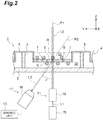
- the sample S is held in a sample container 2 as illustrated in FIG. 2 .
- the sample container 2 is, for example, a microplate.
- the sample container 2 includes a plate-like main body 4 in which a plurality of wells 3 in which the samples S are disposed are arranged in a straight line (or a matrix form), and a plate-like transparent member 5 provided to close one end side of the well 3 on one surface side of the main body 4.
- a membrane filter 6 is disposed in the well 3.
- the membrane filter 6 is a film in which a large number of micropores 7 through which the sample S passes are provided.
- a material of the membrane filter 6 is, for example, polycarbonate or polyethylene terephthalate.
- a thickness of the membrane filter 6 is generally very thin and is, for example, about 7 ⁇ m to 25 ⁇ m. Further, an inner diameter (a diameter) of the micropores 7 is, for example, about 8 ⁇ m to 10 ⁇ m.
- the membrane filter 6 is held at a substantially center position of the well 3 by a support member 8 to partition the well 3 into a first sample holding space V1 on the opposite side to the transparent member 5 and a second sample holding space V2 on the transparent member 5 side.
- the samples S that are observation targets are cancer cells
- the samples S are held on one surface of the membrane filter 6 coated with the extracellular matrix so that the samples S are located on the first sample holding space V1 side.
- Some of the samples S held on the one surface of the membrane filter 6 enter the micropores 7 of the membrane filter 6 over time, and move to the other surface of the membrane filter 6 (that is, the second sample holding space V2) through the micropores 7. Therefore, invasion ability of the cancer cells can be evaluated by observing the sample S present on the one surface of the membrane filter 6 and the sample S present on the other surface of the membrane filter 6 after a predetermined time has elapsed since the sample S came to be held on the one surface of the membrane filter 6.
- the sample observation device 1 includes an irradiation optical system 11, a scanning unit 12, an imaging unit 13, and a computer 14.
- the irradiation optical system 11 irradiates the sample S with the planar light L2 including a wavelength that is transmitted through the membrane filter 6 as excitation light.
- the irradiation optical system 11 includes a light source 15 and a planar light formation unit 16, as illustrated in FIG. 2 .
- the light source 15 outputs light L1 that is a formation source of the planar light L2. Examples of the light source 15 include a laser light source such as a laser diode and a solid-state laser light source. Further, the light source 15 may be a light emitting diode, a super luminescent diode, or a lamp light source.
- the light L1 output from the light source 15 is guided to the planar light formation unit 16.
- the planar light formation unit 16 shapes the light L1 output from the light source 15 into the planar light L2, and irradiates the sample S with the shaped planar light L2 along the optical axis P1.
- an optical axis of the planar light formation unit 16 is the optical axis P1 of the planar light L2.
- the planar light formation unit 16 includes a light shaping element such as a cylindrical lens, an axicon lens, or a spatial light modulator, and is optically coupled to the light source 15.
- the planar light formation unit 16 may include an objective lens, an optical shutter, and the like.
- the membrane filter 6 is made of polycarbonate, the membrane filter 6 is impermeable to light having a wavelength of 400 nm or less. Therefore, it is preferable for the wavelengths of the light L1 and the planar light L2 to be, for example, 450 nm to 750 nm.
- the planar light L2 is thin planar light having a thickness of 2 mm or less in consideration of resolution. Further, when a thickness of the sample S is very small, that is, when a sample S having a thickness equal to or less than Z-direction resolution is observed, a thickness of the planar light L2 does not affect the resolution. In this case, planar light L2 having a thickness exceeding 2 mm may be used.
- the sample S held in the sample container 2 is irradiated with the planar light L2 formed by the irradiation optical system 11.
- the planar light L2 includes a wavelength that is transmitted through the membrane filter 6. Therefore, the irradiation surface R for the planar light L2 with respect to the sample S reaches the second sample holding space V2 through the membrane filter 6 from the first sample holding space V1. Due to the irradiation with the planar light L2, the observation light L3 is generated on the irradiation surface R for the planar light L2.
- the observation light L3 includes, for example, fluorescent light excited in the sample S due to the planar light L2 and scattered light of the planar light L2 scattered on the surface of the membrane filter 6 without passing through the membrane filter 6.
- the scanning unit 12 is a mechanism that scans the sample S with respect to the irradiation surface R for the planar light L2.
- the scanning unit 12 includes a moving stage that moves the sample container 2 that holds the samples S, for example.
- the moving stage scans the sample container 2 in a preset direction according to a control signal from the computer 14. In the embodiment, the moving stage scans the sample container 2 in one direction within a plane orthogonal to the optical axis P1 of the planar light L2.
- a direction of the optical axis P1 of the planar light L2 is referred to as an Z axis
- a scanning direction of the sample container 2 according to the moving stage is referred to as a Y axis
- a direction orthogonal to the Y axis within the plane orthogonal to the optical axis P1 of the planar light L2 is referred to as an X axis, as illustrated in FIG. 2 .
- the irradiation surface R for the planar light L2 with respect to the sample S is a surface within the XZ plane.
- an image formation optical system 17 that forms an image of the observation light L3 generated on the irradiation surface R due to the irradiation with the planar light L2 is provided.
- the image formation optical system 17 includes, for example, an objective lens 18.
- the image formation optical system 17 may include an image formation lens, in addition to the objective lens 18.
- An optical axis of the image formation optical system 17 is an observation axis P2 of the observation light L3. This observation axis P2 is inclined at an inclination angle ⁇ with respect to the irradiation surface R for the planar light L2.
- the inclination angle ⁇ also matches an angle formed by the optical axis P1 of the planar light L2 directed to the sample S and the observation axis P2.
- the inclination angle ⁇ is 10° to 80°.
- the inclination angle ⁇ is preferably 20° to 70° from the viewpoint of improvement of resolution of the observation image. Further, the inclination angle ⁇ is more preferably 30° to 65° from the viewpoint of improvement of the resolution of the observation image and stability of the field of view.
- the imaging unit 13 is configured of an imaging device that images the observation light L3 and outputs fluorescent light image data based on an imaging result.
- the imaging unit 13 includes a first imaging device (a first photodetector) 13A that images fluorescent light generated due to the irradiation with the planar light L2 and a second imaging device (a second photodetector) 13B that images the scattered light of the planar light L2 generated on the surface of the membrane filter 6.
- Examples of the first imaging device 13A and the second imaging device 13B include area image sensors such as CMOS image sensors and CCD image sensors. These area image sensors are disposed on an image formation surface according to the image formation optical system 17, image a light image using, for example, a global shutter or a rolling shutter, and output two-dimensional image data to the computer 14.
- a filter that cuts scattered light may be provided in the first imaging device 13A, and a filter that cuts fluorescent light may be provided in the second imaging device 13B.
- a line scan scheme may be applied to the first imaging device 13A and the second imaging device 13B to partially capture the fluorescent light image and the scattered light image on the irradiation surface R.
- a subarray may be set on the imaging surface of the area image sensor 21.
- the light image of the observation light L3 can be partially captured.
- all pixel rows of the area image sensor 21 may be used as a readout area, and a part of the two-dimensional image may be extracted through a subsequent image process, as illustrated in FIG. 3(b) .
- partial imaging may be performed by using a line sensor 22 instead of the area image sensor 21 and limiting the imaging surface itself to one pixel row, as illustrated in FIG. 3(c) .
- a slit 23 that transmits only a part of the observation light L3 may be disposed on a front surface of the area image sensor 21, and image data of the pixel row 21 a corresponding to the slit 23 may be acquired.
- a point sensor of a photomultiplier tube or the like may be used instead of the area image sensor.
- the computer 14 physically includes a memory such as a RAM and a ROM, a processor (an arithmetic circuit) such as a CPU, a communication interface, a storage unit such as a hard disk, and a display unit such as a display.
- a computer 14 examples include a personal computer, a microcomputer, a cloud server, and a smart device (a smart phone, a tablet terminal, or the like).
- the computer 14 functions as a controller that controls operations of the light source 15, the scanning unit 12, and the imaging unit 13 by a program stored in the memory being executed by a CPU of a computer system.
- the computer 14 as the controller receives an input of a measurement start operation from the user, and drives the light source 15, the scanning unit 12, and the imaging unit 13 in synchronization. Accordingly, the sample container 2 is scanned in the Y direction with respect to the irradiation surface R, and a plurality of XZ images in the irradiation surface R are captured by the imaging unit 13.
- the computer 14 may control the light source 15 so that the light source 15 continuously outputs the light L1 during movement of the sample container 2 by the scanning unit 12, or may control ON/OFF of the output of the light L1 from the light source 15 according to the imaging in the imaging unit 13. Further, when the irradiation optical system 11 includes an optical shutter, the computer 14 may turn ON/OFF the irradiation with the planar light L2 by controlling the optical shutter.
- the computer 14 includes an imaging result reception unit 31, a partial image generation unit 32, an observation image generation unit 33, and an analysis unit 34 as functional components.
- the imaging result reception unit 31 is a unit that receives imaging data from the imaging unit 13. That is, the imaging result reception unit 31 receives fluorescent light image data based on the fluorescent light image included in the observation light L3 from the first imaging device 13A, and receives scattered light image data based on the scattered light image included in the observation light L3 from the second imaging device 13B.
- the imaging result reception unit 31 outputs the received fluorescent light image data and the received scattered light image data to the partial image generation unit 32.
- FIG. 5(a) is a diagram illustrating an example of the fluorescent light image data.
- This fluorescent light image data G corresponds to an XZ image of the fluorescent light generated on the irradiation surface R for the planar light L2.
- the fluorescent light is generated when the fluorescent substance included in the sample S is excited by the planar light L2. Therefore, as illustrated in FIG. 5(a) , a fluorescent light image M1 corresponding to the sample S located on the one surface of the membrane filter 6 and a fluorescent light image M2 corresponding to the sample S located on the other surface of the membrane filter 6 can appear in the fluorescent light image data G. Since the membrane filter 6 does not generate fluorescent light, a fluorescent light image does not appear in an area corresponding to the membrane filter 6.
- FIG. 5(b) illustrates an example of the scattered light image data.
- This scattered light image data F corresponds to an XZ image of the scattered light generated on the irradiation surface R for the planar light L2.
- the scattered light is generated when the planar light L2 is scattered in the membrane filter 6. Therefore, as illustrated in FIG. 5(b) , a scattered light image N1 corresponding to the sample S located on the one surface of the membrane filter 6, a scattered light image N2 corresponding to the sample S located on the other surface of the membrane filter 6, and a scattered light image N3 corresponding to the membrane filter 6 may appear in the scattered light image data F.
- the partial image generation unit 32 generates partial image data based on the fluorescent light image data.
- the partial image generation unit 32 receives the fluorescent light image data G and the scattered light image data F from the imaging unit 13, the partial image generation unit 32 first specifies an area Q corresponding to the membrane filter 6 (see FIG. 5 (b) ) on the basis of the scattered light image N3 in the scattered light image data F.
- the area Q corresponding to the membrane filter 6 may be specified through predetermined image processing, or may be specified on the basis of the thickness of the membrane filter 6.
- the partial image generation unit 32 applies the area Q corresponding to the membrane filter 6 to the fluorescent light image data G, and specifies a first area K1 corresponding to the first sample holding space V1 and a second area K2 corresponding to the second sample holding space V2 in the fluorescent light image data G.
- the partial image generation unit 32 specifies the first area K1 and the second area K2
- the partial image generation unit 32 extracts a portion corresponding to the first area K1 from the fluorescent light image data G, and generates first partial image data E1 corresponding to the first area K1, as illustrated in FIG. 6(a) .
- the partial image generation unit 32 extracts a portion corresponding to the second area K2 from the fluorescent light image data G, and generates second partial image data E2 corresponding to the second area K2, as illustrated in FIG. 6(b) .
- the partial image generation unit 32 outputs the generated first partial image data E1 and the generated second partial image data E2 to the observation image generation unit 33.
- the observation image generation unit 33 generates observation image data on the basis of the partial image data.
- the observation image generation unit 33 compresses the first partial image data E1 and the second partial image data E2 received from the partial image generation unit 32 in a Z-axis direction.
- the partial image data compressed in the Z-axis direction indicates luminance of the fluorescent light in an X-axis direction.
- the sample container 2 is scanned in a Y-axis direction with respect to the irradiation surface R, and a plurality of XZ images on the irradiation surface R are captured by the imaging unit 13. Therefore, the observation image generation unit 33 generates, for the Y-axis direction, a plurality of pieces of partial image data compressed in the Z-axis direction.
- the observation image generation unit 33 synthesizes the partial image data compressed in the Z-axis direction with respect to the first partial image data in the Y-axis direction, and integrates the luminance of the fluorescent light in each of piece of partial image data. Accordingly, as illustrated in FIG. 7(a) , first observation image data J1 corresponding to the first area K1 is generated. Similarly, the observation image generation unit 33 synthesizes the partial image data compressed in the Z-axis direction with respect to the second partial image data E2 in the Y-axis direction, and integrates the luminance of the fluorescent light in each of piece of partial image data. Accordingly, as illustrated in FIG. 7(b) , second observation image data J2 corresponding to the second area K2 is generated. The observation image generation unit 33 outputs the generated first observation image data J1 and the generated second observation image data J2 to the analysis unit 34.
- the analysis unit 34 analyzes the sample S on the basis of the first observation image data J1 and the second observation image data J2.
- a fluorescent light image D1 appearing in the first observation image data J1 represents the sample S remaining in the first sample holding space V1 instead of passing through the membrane filter 6.
- the fluorescent light image D2 appearing in the second observation image data represents the sample S that has passed through the membrane filter 6 and moved to the second sample holding space V2.
- the analysis unit 34 counts the number of samples S located in the first sample holding space V1 by counting the fluorescent light images D1 appearing in the first observation image data J1. Further, the analysis unit 34 counts the number of samples S located in the second sample holding space V2 by counting the fluorescent light images D2 appearing in the second observation image data J2.
- the analysis unit 34 may analyze an intensity of the fluorescent light of each of the sample S located in the first sample holding space V1 and the sample S located in the second sample holding space V2 on the basis of intensities of the fluorescent light of the fluorescent light images D1 and D2.
- FIG. 8 is a flowchart illustrating an example of a sample observation method using the sample observation device 1 illustrated in FIG. 1 .
- this sample observation method includes a preparation step (step S01), an irradiation step (step S02), a scanning step (step S03), an imaging step (step S04), a partial image generation step (step S05), an observation image generation step (Step S06), and an analysis step (step S07).
- the sample S is held in the sample container 2.
- the sample S is stained with a fluorescent substance excited by light having a wavelength that is transmitted through the membrane filter 6.
- the sample S is held on the one surface of the membrane filter 6 coated with the extracellular matrix so that the sample S is located on the first sample holding space V1 side.
- the sample container 2 is set in the scanning unit 12.
- the sample S is irradiated with the planar light L2.
- the light source 15 is driven on the basis of a control signal from the computer 14, and the light L 1 is output from the light source 15.
- the light L1 output from the light source 15 is shaped by the planar light formation unit 16 to become the planar light L2, and the sample S held in the sample container 2 is irradiated with the planar light L2.
- the sample S is scanned with respect to the irradiation surface R for the planar light L2.
- the scanning unit 12 is driven in synchronization with the driving of the light source 15 on the basis of a control signal from the computer 14. Accordingly, the sample container 2 is linearly driven at a constant speed in the Y-axis direction, and the sample S in the well 3 is scanned with respect to the irradiation surface R for the planar light L2.
- the observation light L3 generated due to the irradiation with the planar light L2 is imaged. More specifically, in the imaging step, the observation light L3 generated in the sample S due to the irradiation with the planar light L2 is formed as an image on an image formation surface of the imaging unit 13 by the image formation optical system 17 having the observation axis P2 inclined with respect to the irradiation surface R. In the imaging step, a plurality of partial images corresponding to parts of the light image according to the fluorescent light image formed by the image formation optical system 17 are acquired by the first imaging device 13A, and a plurality of partial images corresponding to parts of the light image according to the scattered light image are acquired by the second imaging device 13B.
- the first partial image data E1 corresponding to the first area K1 and the second partial image data E2 corresponding to the second area K2 are generated.
- the area Q (see FIG. 5(b) ) corresponding to the membrane filter 6 is first specified on the basis of the scattered light image data F. Then, the area Q corresponding to the membrane filter 6 is applied to the fluorescent light image data G, and the first area K1 corresponding to the first sample holding space V1 and the second area K2 corresponding to the second sample holding space V2 are specified in the fluorescent light image data G (see FIG. 5(c) ).
- a part corresponding to the first area K1 is extracted from the fluorescent light image data G, and the first partial image data E1 corresponding to the first area K1 is generated (See FIG. 6(a) ).
- a part corresponding to the second area K2 is extracted from the fluorescent light image data G, and the second partial image data E2 corresponding to the second area K2 is generated (see FIG. 6(b) ).
- the first observation image data J1 is generated on the basis of the first partial image data E1
- the second observation image data J2 is generated on the basis of the second partial image data E2. More specifically, in the observation image generation step, for the first partial image data E1, a plurality of pieces of partial image data compressed in the Z-axis direction is synthesized in the Y-axis direction, and the first observation image data J1 corresponding to the first area K1 is generated (see FIG. 7(a) ). Similarly, for the second partial image data E2, a plurality of pieces of partial image data compressed in the Z-axis direction is synthesized in the Y-axis direction, the second observation image data J2 corresponding to the second area K2 is generated. (see FIG. 7(b) ).
- the sample S is analyzed on the basis of the first observation image data J1 and the second observation image data J2.
- the number of samples S located in the first sample holding space V1 is counted by counting the fluorescent light images D1 appearing in the first observation image data J1.
- the number of samples S located in the second sample holding space V2 is counted by counting the fluorescent light images D2 appearing in the second observation image data J2.
- An intensity of the fluorescent light of each of the sample S located in the first sample holding space V1 and the sample S located in the second sample holding space V2 is analyzed.
- the sample is irradiated with the planar light L2 including the wavelength that is transmitted through the membrane filter 6 as excitation light. Accordingly, the fluorescent light image data G based on the imaging result of the observation light L3 including the fluorescent light from both the first sample holding space V1 and the second sample holding space V2 partitioned by the membrane filter 6 can be acquired. Further, in the sample observation device 1, the first area K1 corresponding to the first sample holding space V1 and the second area K2 corresponding to the second sample holding space V2 are specified from the acquired fluorescent light image data G, and the observation image data based on the partial image data of each area is generated. Accordingly, both the sample S that has moved through the membrane filter 6 and the sample S that has not moved can be observed.
- the imaging unit 13 includes the first imaging device 13A that images fluorescent light and the second imaging device 13B that images scattered light.
- the partial image generation unit 32 specifies the first area K1 and the second area K2 in the fluorescent light image data on the basis of the scattered light image data. Accordingly, the area Q corresponding to the membrane filter 6 in the fluorescent light image data G can be specified using the scattered light image data F. Therefore, the first area K1 and the second area K2 in the fluorescent light image data G can be easily specified.
- the analysis unit 34 counts the number of samples S located in the first sample holding space V1 and the number of samples S located in the second sample holding space V2 on the basis of the first observation image data J1 and the second observation image data J2. Accordingly, the evaluation of the sample S can be performed rapidly.
- an image formation optical system 17 that has an observation axis P2 that is inclined with respect to the irradiation surface R3 and that forms the observation light L3 as an image on the imaging unit 13 is provided.
- a field-of-view selection operation becomes unnecessary, and scanning and imaging of the sample S can be performed simultaneously. Therefore, improvement of a throughput until the observation image data is obtained can be achieved.
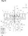
- FIG. 9 is a block diagram illustrating another embodiment of the sample observation device. As illustrated in FIG. 9 , a sample observation device 41 according to another embodiment is different from the above-described sample observation device 1 in that the irradiation optical system 11 includes a first irradiation optical system 11A and a second irradiation optical system 11B.
- the sample S is stained by a first fluorescent substance excited by light having a wavelength that is transmitted through a membrane filter 6 and a second fluorescent substance excited by light having a wavelength that is not transmitted through the membrane filter 6.
- first fluorescent substance include calcein AM (excitation wavelength 490 nm/fluorescent light wavelength 525 nm).
- the second fluorescent substance include calcein blue (excitation wavelength 360 nm/fluorescent light wavelength 450 nm).
- the first irradiation optical system 11A includes a first light source 15A and a first planar light formation unit 16A.
- the first light source 15A outputs first light L1a that is transmitted through the membrane filter 6 and that includes a wavelength that excites the first fluorescent substance.
- the first planar light formation unit 16A shapes the first light L1a output from the first light source 15A into first planar light L2a, and irradiates the sample S with the first planar light L2a along an optical axis P1. Since the first planar light L2a is transmitted through the membrane filter 6, an irradiation surface Ra for the first planar light L2a reaches a second sample holding space V2 through the membrane filter 6 from a first sample holding space V1.
- the second irradiation optical system 11B includes a second light source 15B and a second planar light formation unit 16B.
- the second light source 15B outputs second light L1b that is not transmitted through the membrane filter 6 and that includes a wavelength that excites the second fluorescent substance.
- the second planar light formation unit 16B shapes the second light L1b output from the second light source 15B into second planar light L2b, and irradiates the sample S with the second planar light L2b, for example, in a state in which the second planar light L2b is caused to be coaxial with the optical axis P1 by a mirror 42 and a dichroic mirror 43. Since the second planar light L2b is not transmitted through the membrane filter 6, an irradiation surface Rb for the second planar light L2b is present only in the second sample holding space V2.
- the observation light L3 includes the first fluorescent light excited in the sample S by the first planar light L2a and the second fluorescent light excited in the sample S by the second planar light L2b.
- the first fluorescent light is formed as an image on an imaging surface of the first imaging device 13A by the image formation optical system 17A having the observation axis P2 inclined with respect to the irradiation surface Ra
- the second fluorescent light is split from the first fluorescent light by, for example, a dichroic mirror 44 and a mirror 45 and formed as an image on an image formation surface of the second imaging device 13B by the image formation optical system 17B having the observation axis P2 inclined with respect to the irradiation surface Rb.
- the first imaging device 13A captures a first fluorescent light image generated due to the irradiation with the first planar light L2a, and outputs the first fluorescent light image data to the computer 14.
- the second imaging device 13B captures a second fluorescence light image generated due to the irradiation with the second planar light L2b and outputs the second fluorescent light image data to the computer 14.
- a filter that cuts the second fluorescent light may be provided in the first imaging device 13A, and a filter that cuts the first fluorescent light may be provided in the second imaging device 13B.
- FIG. 11(a) is a diagram illustrating an example of the first fluorescent light image data.
- the irradiation surface Ra for the first planar light L2a reaches the second sample holding space V2 through the membrane filter 6 from the first sample holding space V1. Therefore, a fluorescent light image M1 corresponding to the sample S located on one surface of the membrane filter 6 and a fluorescent light image M2 corresponding to the sample S located on the other surface of the membrane filter 6 can appear in the first fluorescent light image data G1.
- FIG. 11(b) is a diagram illustrating an example of the second fluorescent light image data.
- the irradiation surface Rb for the second planar light L2b is present only in the second sample holding space V2. Therefore, only a fluorescent light image M3 corresponding to the sample S located on the other surface of the membrane filter 6 can appear in the second fluorescent light image data G2.
- the partial image generation unit 32 extracts an area Q1 corresponding to the membrane filter 6 on the basis of a thickness of the membrane filter 6, and extracts an area Q2 corresponding to the second sample holding spaces V2 from the second fluorescent light image data G2 on the basis of a range in which the fluorescent light image M3 appears.
- the partial image generation unit 32 applies the area Q1 corresponding to the membrane filter 6 and the area Q2 corresponding to the second sample holding space V2 to the first fluorescent light image data G1, and specifies the first area K1 corresponding to the first sample holding space V1 and the second area K2 corresponding to the second sample holding space V2 in the first fluorescent light image data G1.
- sample observation device 41 In such a sample observation device 41, the same operation and effects as in the sample observation device 1 described above can be obtained, and both the sample S that has moved through the membrane filter 6 and the sample S that has not moved can be observed. Further, in the sample observation device 1, an area corresponding to the sample holding space V1 and an area corresponding to the second sample holding space V2 can be easily discriminated on the basis of the fluorescent light images M1 and M2 of the sample S included in the first fluorescent light image data G1 and the fluorescent light image M3 of the sample included in the second fluorescent light image data G2. Therefore, the first area K1 and the second area K2 in the first fluorescent light image data G1 can be easily specified through collation of the first fluorescent light image data G1 with the second fluorescent light image data G2.
- the sample S is stained with the first fluorescent substance excited by the light having a wavelength that is transmitted through the membrane filter 6, and the solution including the second fluorescent substance excited by the light having a wavelength that is not transmitted through the membrane filter 6 may be injected into the first sample holding space V1 and the second sample holding space V2.
- the fluorescent light image M1 corresponding to the sample S located on the one surface of the membrane filter 6 and the fluorescent light image M2 corresponding to the sample S located on the other surface of the membrane filter 6 can appear in the first fluorescent light image data G1. Further, as illustrated in FIG. 12(b) , in the second fluorescent light image data G2, a fluorescent light image corresponding to the sample S does not appear, and only a fluorescent light image M4 corresponding to the solution in the second sample holding space V2 can appear.
- the partial image generation unit 32 extracts the area Q1 corresponding to the membrane filter 6 on the basis of a thickness of the membrane filter 6, and extracts the area Q2 corresponding to the second sample holding spaces V2 from the second fluorescent light image data G2 on the basis of a range in which the fluorescent light image M4 appears.
- the partial image generation unit 32 applies the area Q1 corresponding to the membrane filter 6 and the area Q2 corresponding to the second sample holding space V2 to the first fluorescent light image data G1, and specifies the first area K1 corresponding to the first sample holding space V1 and the second area K2 corresponding to the second sample holding space V2 in the first fluorescent light image data G1.
- the same operation and effects as in the sample observation device 1 described above can be obtained, and both the sample S that has moved through the membrane filter 6 and the sample S that has not moved can be observed. Further, the area corresponding to the first sample holding space V1 and the area corresponding to the second sample holding space V2 can be easily discriminated on the basis of the fluorescent light image M4 of the solution. Therefore, the first area K1 and the second area K2 in the first fluorescent light image data G1 can be more easily specified through collation of the first fluorescent light image data G1 with the second fluorescent light image data G2.
- the present disclosure is not limited to the above embodiment.
- the irradiation optical system 11 that outputs the planar light and the imaging unit 13 that adopts the line scan scheme are combined, for example, in the above-described embodiment, another scheme may be adopted as long as a cross section in a depth direction of the well 3 in the sample container 2 can be measured at a time.
- another scheme may be adopted as long as a cross section in a depth direction of the well 3 in the sample container 2 can be measured at a time.
- an optical system of oblique plane microscopy described in US Patent No. 8582203 may be adopted.
Landscapes
- Physics & Mathematics (AREA)
- Chemical & Material Sciences (AREA)
- General Physics & Mathematics (AREA)
- Health & Medical Sciences (AREA)
- Analytical Chemistry (AREA)
- Engineering & Computer Science (AREA)
- Life Sciences & Earth Sciences (AREA)
- Optics & Photonics (AREA)
- Immunology (AREA)
- General Health & Medical Sciences (AREA)
- Biochemistry (AREA)
- Pathology (AREA)
- Nuclear Medicine, Radiotherapy & Molecular Imaging (AREA)
- Multimedia (AREA)
- Organic Chemistry (AREA)
- Molecular Biology (AREA)
- Computer Vision & Pattern Recognition (AREA)
- Proteomics, Peptides & Aminoacids (AREA)
- Zoology (AREA)
- Wood Science & Technology (AREA)
- Biomedical Technology (AREA)
- Dispersion Chemistry (AREA)
- Signal Processing (AREA)
- Radiology & Medical Imaging (AREA)
- Biophysics (AREA)
- Toxicology (AREA)
- Biotechnology (AREA)
- Microbiology (AREA)
- Theoretical Computer Science (AREA)
- Quality & Reliability (AREA)
- Medical Informatics (AREA)
- Bioinformatics & Cheminformatics (AREA)
- General Engineering & Computer Science (AREA)
- Genetics & Genomics (AREA)
- Chemical Kinetics & Catalysis (AREA)
- Investigating, Analyzing Materials By Fluorescence Or Luminescence (AREA)
- Microscoopes, Condenser (AREA)
Abstract
Description
- The present disclosure relates to a sample observation device and a sample observation method.
- In the related art, a scheme for evaluating the mobility of a sample such as a cancer cell using a membrane filter is known (see, for example, Non-Patent
Literature 1 to 3). An example of the evaluation of the mobility includes invasive ability evaluation (Cell Invasion Assay). Invasion ability evaluation is mainly to evaluate the ability of cancer cells to migrate while destroying an extracellular matrix. In the invasive ability evaluation, the ability of cells to pass through a membrane filter coated with an extracellular matrix is evaluated. - Cancer cells have properties of migration to more nutritious areas. Therefore, in a sample container, one of two spaces partitioned by a membrane filter is filled with an undernourished solution and the other is filled with a nutritious solution, such that cells can migrate from the one space to the other space through micropores of the membrane filter.
-
- [Non-Patent Literature 1] Nina Kramer et al., "In vitro cell migration and invasion assays" Mutation Research 752 (2013) 10-24
- [Non-Patent Literature 2] Keren I. Hulkower and Renee L. Herber "Cell Migration and Invasion Assays as Tools for Drug Discovery" Pharmaceutics 2011, 3, 107-124; doi: 10.3390/pharmaceutics3010107
- [Non-Patent Literature 3] Vladimir Mastyugin et al., "A Quantitative High-Throughput Endothelial Cell Migration Assay" Journal of Biomolecular Screening 9 (8); 2004
- In the related art, a sample that has moved from one space to the other space through a membrane filter has been labeled with fluorescence and observed with a plate reader, and comparison with a control (a state of being not treated with a drug) has been performed. However, in such a scheme of the related art, it is difficult to observe both the sample that has moved from the one space to the other space through the membrane filter and a sample that has not moved.
- With only observing the sample that has moved through the membrane filter, it is difficult to distinguish a phenomenon such as cell proliferation or cell death from the invasion ability of the cell according to a case in which an observation time becomes longer or an action of a drug. Therefore, it is conceivable that the accuracy of evaluation of invasion ability cannot be sufficiently secured. In order to improve the accuracy of the evaluation of the invasion ability, it is preferable to obtain the viability of each of the sample that has moved through the membrane filter and the sample that has not moved.
- The present disclosure has been made to solve the above-described problems, and an object thereof is to provide a sample observation device and a sample observation method capable of observing both a sample that has moved through a membrane filter and a sample that has not moved.
- A sample observation device according to an aspect of the present disclosure is a sample observation device for observing a sample held in a sample container having a first sample holding space and a second sample holding space partitioned by a membrane filter, the sample observation device including: an irradiation optical system that irradiates the sample with planar light including a wavelength that is transmitted through the membrane filter as excitation light; a scanning unit that scans the sample with respect to an irradiation surface for the planar light; an imaging unit that images observation light including fluorescent light generated due to the irradiation with the planar light and outputs fluorescent light image data based on an imaging result; a partial image generation unit that specifies a first area corresponding to the first sample holding space and a second area corresponding to the second sample holding space in the fluorescent light image data, and generates first partial image data corresponding to the first area and second partial image data corresponding to the second area; an observation image generation unit that generates first observation image data on the basis of the first partial image data and generates second observation image data on the basis of the second partial image data; and an analysis unit that analyzes the sample on the basis of the first observation image data and the second observation image data.
- In the sample observation device, the sample is irradiated with the planar light including the wavelength that is transmitted through the membrane filter as excitation light. Accordingly, the fluorescent light image data based on the imaging result of the observation light including the fluorescent light from both the first sample holding space and the second sample holding space partitioned by the membrane filter can be acquired. Further, in the sample observation device, the first area corresponding to the first sample holding space and the second area corresponding to the second sample holding space are specified from the acquired fluorescent light image data, and the observation image data based on the partial image data of each area is generated. Accordingly, both the sample that has moved through the membrane filter and the sample that has not moved can be observed.
- Further, the imaging unit may further image scattered light of the excitation light generated due to the irradiation with the planar light, and output scattered light image data based on an imaging result, and the partial image generation unit may specify the first area and the second area in the fluorescent light image data on the basis of the scattered light image data. In this case, the area corresponding to the membrane filter in the fluorescent light image data can be specified using the scattered light image data. Therefore, the first area and the second area in the fluorescent light image data can be easily specified.
- Further, the irradiation optical system may irradiate the sample with first planar light including a wavelength that is transmitted through the membrane filter and second planar light including a wavelength that is not transmitted through the membrane filter as the excitation light, the imaging unit may image observation light including first fluorescent light generated due to irradiation with the first planar light and observation light including second fluorescent light generated due to irradiation with the second planar light, and output first fluorescent light image data and second fluorescent light image data based on respective imaging results, and the partial image generation unit may specify the first area and the second area in the first fluorescent light image data on the basis of the second fluorescent light image data. In this case, fluorescent light images from both the sample holding spaces with the membrane filter sandwiched therebetween is included in the first fluorescent light image data, whereas only the fluorescent light image from one of the sample holding spaces with the membrane filter sandwiched therebetween is included in the second fluorescent light image data. Therefore, the first area and the second area in the first fluorescent light image data can be easily specified through collation of the first fluorescent light image data and the second fluorescent light image data.
- Further, the sample may be stained with a first fluorescent substance excited by light having a wavelength that is transmitted through the membrane filter, and a second fluorescent substance excited by light having a wavelength that is not transmitted through the membrane filter. In this case, the area corresponding to the first sample holding space and the area corresponding to the second sample holding space can be easily discriminated on the basis of the fluorescent light image of the sample included in the first fluorescent light image data and the fluorescent light image of the sample included in the second fluorescent light image data. Therefore, the first area and the second area in the first fluorescent light image data can be easily specified through collation of the first fluorescent light image data and the second fluorescent light image data.
- Further, the sample may be stained with a first fluorescent substance excited by light having a wavelength that is transmitted through the membrane filter, and a solution including a second fluorescent substance excited by light having a wavelength that is not transmitted through the membrane filter may be injected into the first sample holding space and the second sample holding space. In this case, the area corresponding to the first sample holding space and the area corresponding to the second sample holding space can be easily discriminated on the basis of a fluorescent light image of a solution. Therefore, the first area and the second area in the first fluorescent light image data can be easily specified through collation of the first fluorescent light image data and the second fluorescent light image data.
- Further, the analysis unit may count the number of samples located in the first sample holding space and the number of samples located in the second sample holding space on the basis of the first observation image data and the second observation image data. Accordingly, evaluation of the samples can be performed rapidly.
- Further, the sample observation device may further include an image formation optical system that has an observation axis inclined with respect to the irradiation surface and that forms an image of the observation light on the imaging unit. In this case, a field-of-view selection operation becomes unnecessary, and scanning and imaging of the sample can be performed simultaneously. Therefore, improvement of a throughput until the observation image data is obtained can be achieved.
- A sample observation method according to an aspect of the present disclosure is a sample observation method for observing a sample held in a sample container having a first sample holding space and a second sample holding space partitioned by a membrane filter, the sample observation method including: an irradiation step of irradiating the sample with planar light including a wavelength that is transmitted through the membrane filter as excitation light; a scanning step of scanning the sample with respect to an irradiation surface for the planar light; an imaging step of imaging observation light including fluorescent light generated due to the irradiation with the planar light and outputting fluorescent light image data based on an imaging result; a partial image generation step of specifying a first area corresponding to the first sample holding space and a second area corresponding to the second sample holding space in the fluorescent light image data, and generating first partial image data corresponding to the first area and second partial image data corresponding to the second area; an observation image generation step of generating first observation image data on the basis of the first partial image data and generating second observation image data on the basis of the second partial image data; and an analysis step of analyzing the sample on the basis of the first observation image data and the second observation image data.
- In the sample observation method, the sample is irradiated with the planar light including the wavelength that is transmitted through the membrane filter as excitation light. Accordingly, the fluorescent light image data based on the imaging result of the observation light including the fluorescent light from both the first sample holding space and the second sample holding space partitioned by the membrane filter can be acquired. Further, in the sample observation method, the first area corresponding to the first sample holding space and the second area corresponding to the second sample holding space are specified from the acquired fluorescent light image data, and the observation image data based on the partial image data of each area is generated. Accordingly, both the sample that has moved through the membrane filter and the sample that has not moved can be observed.
- Further, the imaging step may include further imaging scattered light of the excitation light generated due to the irradiation with the planar light, and outputting scattered light image data based on an imaging result, and the partial image generation step may include specifying the first area and the second area in the fluorescent light image data on the basis of the scattered light image data. In this case, the area corresponding to the membrane filter in the fluorescent light image data can be specified using the scattered light image data. Therefore, the first area and the second area in the fluorescent light image data can be easily specified.
- Further, the irradiation step may include irradiating the sample with first planar light including a wavelength that is transmitted through the membrane filter and second planar light including a wavelength that is not transmitted through the membrane filter as the excitation light, the imaging step may include imaging observation light including first fluorescent light generated due to irradiation with the first planar light and observation light including second fluorescent light generated due to irradiation with the second planar light, and outputting first fluorescent light image data and second fluorescent light image data based on respective imaging results, and the partial image generation step may include specifying the first area and the second area in the first fluorescent light image data on the basis of the second fluorescent light image data. In this case, fluorescent light images from both the sample holding spaces with the membrane filter sandwiched therebetween is included in the first fluorescent light image data, whereas only the fluorescent light image from one of the sample holding spaces with the membrane filter sandwiched therebetween is included in the second fluorescent light image data. Therefore, the first area and the second area in the first fluorescent light image data can be easily specified through collation of the first fluorescent light image data and the second fluorescent light image data.
- Further, the sample observation method may further include a preparation step of staining the sample with a first fluorescent substance excited by light having a wavelength that is transmitted through the membrane filter, and a second fluorescent substance excited by light having a wavelength that is not transmitted through the membrane filter. In this case, the area corresponding to the first sample holding space and the area corresponding to the second sample holding space can be easily discriminated on the basis of the fluorescent light image of the sample included in the first fluorescent light image data and the fluorescent light image of the sample included in the second fluorescent light image data. Therefore, the first area and the second area in the first fluorescent light image data can be easily specified through collation of the first fluorescent light image data and the second fluorescent light image data.
- Further, the sample observation method may further include a preparation step of staining the sample with a first fluorescent substance excited by light having a wavelength that is transmitted through the membrane filter, and injecting a solution including a second fluorescent substance excited by light having a wavelength that is not transmitted through the membrane filter into the first sample holding space and the second sample holding space. In this case, the area corresponding to the first sample holding space and the area corresponding to the second sample holding space can be easily discriminated on the basis of a fluorescent light image of a solution. Therefore, the first area and the second area in the first fluorescent light image data can be easily specified through collation of the first fluorescent light image data and the second fluorescent light image data.
- Further, the analysis step may include counting the number of samples located in the first sample holding space and the number of samples located in the second sample holding space on the basis of the first observation image data and the second observation image data. Accordingly, evaluation of the samples can be performed rapidly.
- Further, the imaging step may include forming an image of the observation light according to an observation axis inclined with respect to the irradiation surface. In this case, a field-of-view selection operation becomes unnecessary, and scanning and imaging of the sample can be performed simultaneously. Therefore, improvement of a throughput until the observation image data is obtained can be achieved.
- In the sample observation device and the sample observation method, both the sample that has moved through the membrane filter and the sample that has not moved can be observed.
-
-
FIG. 1 is a block diagram illustrating an embodiment of a sample observation device. -
FIG. 2 is a schematic diagram illustrating a configuration example of an irradiation optical system, a sample container, and an image formation optical system in the sample observation device illustrated inFIG. 1 . -
FIG. 3 is a diagram illustrating a configuration example of an imaging unit. -
FIG. 4 is a block diagram illustrating an example of functional components of a computer constituting the sample observation device. -
FIG. 5(a) is a diagram illustrating an example of fluorescent light image data, 5(b) is a diagram illustrating an example of scattered light image data, and 5(c) is a diagram illustrating a specific state of a first area and a second area. -
FIG. 6(a) is a diagram illustrating an example of first partial image data, and 6(b) is a diagram illustrating an example of second partial image data. -
FIG. 7(a) is a diagram illustrating an example of first observation image data, and 7(b) is a diagram illustrating an example of second observation image data. -
FIG. 8 is a flowchart illustrating an example of a sample observation method using the sample observation device illustrated inFIG. 1 . -
FIG. 9 is a block diagram illustrating another form of the sample observation device. -
FIG. 10 is a schematic diagram illustrating a configuration example of an irradiation optical system, a sample container, and an image formation optical system in the sample observation device illustrated inFIG. 9 . -
FIG. 11(a) is a diagram illustrating an example of first fluorescent light image data,FIG. 11(b) is a diagram illustrating an example of second fluorescent light image data, andFIG. 11(c) is a diagram illustrating a specific state of the first area and the second area. -
FIG. 12(a) is a diagram illustrating another example of the first fluorescent light image data,FIG. 12(b) is a diagram illustrating another example of the second fluorescent light image data, andFIG. 12(c) is a specific state of the first area and the second area. - Hereinafter, preferred embodiments of a sample observation device and a sample observation method according to an aspect of the present invention will be described in detail with reference to the drawings.
-
FIG. 1 is a block diagram illustrating an embodiment of a sample observation device. Thissample observation device 1 is a device that causes fluorescent light and/or scattered light generated inside a sample S to be formed as an image on an image formation surface to acquire observation image data of the sample S, and analyzes and evaluates the sample S on the basis of the observation image data. - An example of this type of
sample observation device 1 includes a slide scanner that acquires and displays an image of the sample S held on a slide glass, or a plate reader that acquires image data of the sample S held on a microplate and analyzes the image data. Examples of the sample S that is an observation target include a cell and tissue of a human or an animal. The sample S is stained with a fluorescent substance excited by planar light L2 to be described. Examples of the fluorescent substance include calcein AM (excitation wavelength 490 nm/fluorescent light wavelength 525 nm), calcein blue (excitation wavelength 360 nm/fluorescent light wavelength 450 nm). When these fluorescent substances are used, living cells can be selectively stained. - The sample S is held in a
sample container 2 as illustrated inFIG. 2 . Thesample container 2 is, for example, a microplate. Thesample container 2 includes a plate-likemain body 4 in which a plurality ofwells 3 in which the samples S are disposed are arranged in a straight line (or a matrix form), and a plate-liketransparent member 5 provided to close one end side of thewell 3 on one surface side of themain body 4. - A
membrane filter 6 is disposed in thewell 3. Themembrane filter 6 is a film in which a large number ofmicropores 7 through which the sample S passes are provided. A material of themembrane filter 6 is, for example, polycarbonate or polyethylene terephthalate. A thickness of themembrane filter 6 is generally very thin and is, for example, about 7 µm to 25 µm. Further, an inner diameter (a diameter) of themicropores 7 is, for example, about 8 µm to 10 µm. Themembrane filter 6 is held at a substantially center position of thewell 3 by asupport member 8 to partition thewell 3 into a first sample holding space V1 on the opposite side to thetransparent member 5 and a second sample holding space V2 on thetransparent member 5 side. - When the samples S that are observation targets are cancer cells, the samples S are held on one surface of the
membrane filter 6 coated with the extracellular matrix so that the samples S are located on the first sample holding space V1 side. Some of the samples S held on the one surface of themembrane filter 6 enter themicropores 7 of themembrane filter 6 over time, and move to the other surface of the membrane filter 6 (that is, the second sample holding space V2) through themicropores 7. Therefore, invasion ability of the cancer cells can be evaluated by observing the sample S present on the one surface of themembrane filter 6 and the sample S present on the other surface of themembrane filter 6 after a predetermined time has elapsed since the sample S came to be held on the one surface of themembrane filter 6. - As illustrated in
FIG. 1 , thesample observation device 1 includes an irradiationoptical system 11, ascanning unit 12, animaging unit 13, and acomputer 14. The irradiationoptical system 11 irradiates the sample S with the planar light L2 including a wavelength that is transmitted through themembrane filter 6 as excitation light. The irradiationoptical system 11 includes alight source 15 and a planarlight formation unit 16, as illustrated inFIG. 2 . Thelight source 15 outputs light L1 that is a formation source of the planar light L2. Examples of thelight source 15 include a laser light source such as a laser diode and a solid-state laser light source. Further, thelight source 15 may be a light emitting diode, a super luminescent diode, or a lamp light source. The light L1 output from thelight source 15 is guided to the planarlight formation unit 16. - The planar
light formation unit 16 shapes the light L1 output from thelight source 15 into the planar light L2, and irradiates the sample S with the shaped planar light L2 along the optical axis P1. In the embodiment, an optical axis of the planarlight formation unit 16 is the optical axis P1 of the planar light L2. The planarlight formation unit 16 includes a light shaping element such as a cylindrical lens, an axicon lens, or a spatial light modulator, and is optically coupled to thelight source 15. The planarlight formation unit 16 may include an objective lens, an optical shutter, and the like. - When the
membrane filter 6 is made of polycarbonate, themembrane filter 6 is impermeable to light having a wavelength of 400 nm or less. Therefore, it is preferable for the wavelengths of the light L1 and the planar light L2 to be, for example, 450 nm to 750 nm. When observation is performed in a thickness direction of the sample S, it is preferable for the planar light L2 to be thin planar light having a thickness of 2 mm or less in consideration of resolution. Further, when a thickness of the sample S is very small, that is, when a sample S having a thickness equal to or less than Z-direction resolution is observed, a thickness of the planar light L2 does not affect the resolution. In this case, planar light L2 having a thickness exceeding 2 mm may be used. - The sample S held in the
sample container 2 is irradiated with the planar light L2 formed by the irradiationoptical system 11. As described above, the planar light L2 includes a wavelength that is transmitted through themembrane filter 6. Therefore, the irradiation surface R for the planar light L2 with respect to the sample S reaches the second sample holding space V2 through themembrane filter 6 from the first sample holding space V1. Due to the irradiation with the planar light L2, the observation light L3 is generated on the irradiation surface R for the planar light L2. The observation light L3 includes, for example, fluorescent light excited in the sample S due to the planar light L2 and scattered light of the planar light L2 scattered on the surface of themembrane filter 6 without passing through themembrane filter 6. - The
scanning unit 12 is a mechanism that scans the sample S with respect to the irradiation surface R for the planar light L2. Thescanning unit 12 includes a moving stage that moves thesample container 2 that holds the samples S, for example. The moving stage scans thesample container 2 in a preset direction according to a control signal from thecomputer 14. In the embodiment, the moving stage scans thesample container 2 in one direction within a plane orthogonal to the optical axis P1 of the planar light L2. In the following description, a direction of the optical axis P1 of the planar light L2 is referred to as an Z axis, a scanning direction of thesample container 2 according to the moving stage is referred to as a Y axis, and a direction orthogonal to the Y axis within the plane orthogonal to the optical axis P1 of the planar light L2 is referred to as an X axis, as illustrated inFIG. 2 . The irradiation surface R for the planar light L2 with respect to the sample S is a surface within the XZ plane. - In the embodiment, as illustrated in
FIG. 2 , an image formationoptical system 17 that forms an image of the observation light L3 generated on the irradiation surface R due to the irradiation with the planar light L2 is provided. As illustrated inFIG. 2 , the image formationoptical system 17 includes, for example, anobjective lens 18. The image formationoptical system 17 may include an image formation lens, in addition to theobjective lens 18. An optical axis of the image formationoptical system 17 is an observation axis P2 of the observation light L3. This observation axis P2 is inclined at an inclination angle θ with respect to the irradiation surface R for the planar light L2. The inclination angle θ also matches an angle formed by the optical axis P1 of the planar light L2 directed to the sample S and the observation axis P2. The inclination angle θ is 10° to 80°. The inclination angle θ is preferably 20° to 70° from the viewpoint of improvement of resolution of the observation image. Further, the inclination angle θ is more preferably 30° to 65° from the viewpoint of improvement of the resolution of the observation image and stability of the field of view. - As illustrated in
FIG. 1 , theimaging unit 13 is configured of an imaging device that images the observation light L3 and outputs fluorescent light image data based on an imaging result. In the embodiment, theimaging unit 13 includes a first imaging device (a first photodetector) 13A that images fluorescent light generated due to the irradiation with the planar light L2 and a second imaging device (a second photodetector) 13B that images the scattered light of the planar light L2 generated on the surface of themembrane filter 6. - Examples of the
first imaging device 13A and thesecond imaging device 13B include area image sensors such as CMOS image sensors and CCD image sensors. These area image sensors are disposed on an image formation surface according to the image formationoptical system 17, image a light image using, for example, a global shutter or a rolling shutter, and output two-dimensional image data to thecomputer 14. A filter that cuts scattered light may be provided in thefirst imaging device 13A, and a filter that cuts fluorescent light may be provided in thesecond imaging device 13B. - A line scan scheme may be applied to the
first imaging device 13A and thesecond imaging device 13B to partially capture the fluorescent light image and the scattered light image on the irradiation surface R. For example, as illustrated inFIG. 3(a) , a subarray may be set on the imaging surface of thearea image sensor 21. In this case, since only apixel row 21a included in the subarray can be read, the light image of the observation light L3 can be partially captured. Further, all pixel rows of thearea image sensor 21 may be used as a readout area, and a part of the two-dimensional image may be extracted through a subsequent image process, as illustrated inFIG. 3(b) . - Further, partial imaging may be performed by using a
line sensor 22 instead of thearea image sensor 21 and limiting the imaging surface itself to one pixel row, as illustrated inFIG. 3(c) . As illustrated inFIG. 3(d) , a slit 23 that transmits only a part of the observation light L3 may be disposed on a front surface of thearea image sensor 21, and image data of thepixel row 21 a corresponding to the slit 23 may be acquired. When the slit 23 is used, a point sensor of a photomultiplier tube or the like may be used instead of the area image sensor. - The
computer 14 physically includes a memory such as a RAM and a ROM, a processor (an arithmetic circuit) such as a CPU, a communication interface, a storage unit such as a hard disk, and a display unit such as a display. Examples of such acomputer 14 include a personal computer, a microcomputer, a cloud server, and a smart device (a smart phone, a tablet terminal, or the like). Thecomputer 14 functions as a controller that controls operations of thelight source 15, thescanning unit 12, and theimaging unit 13 by a program stored in the memory being executed by a CPU of a computer system. - The
computer 14 as the controller receives an input of a measurement start operation from the user, and drives thelight source 15, thescanning unit 12, and theimaging unit 13 in synchronization. Accordingly, thesample container 2 is scanned in the Y direction with respect to the irradiation surface R, and a plurality of XZ images in the irradiation surface R are captured by theimaging unit 13. Thecomputer 14 may control thelight source 15 so that thelight source 15 continuously outputs the light L1 during movement of thesample container 2 by thescanning unit 12, or may control ON/OFF of the output of the light L1 from thelight source 15 according to the imaging in theimaging unit 13. Further, when the irradiationoptical system 11 includes an optical shutter, thecomputer 14 may turn ON/OFF the irradiation with the planar light L2 by controlling the optical shutter. - Further, as illustrated in
FIG. 4 , thecomputer 14 includes an imagingresult reception unit 31, a partialimage generation unit 32, an observationimage generation unit 33, and ananalysis unit 34 as functional components. The imagingresult reception unit 31 is a unit that receives imaging data from theimaging unit 13. That is, the imagingresult reception unit 31 receives fluorescent light image data based on the fluorescent light image included in the observation light L3 from thefirst imaging device 13A, and receives scattered light image data based on the scattered light image included in the observation light L3 from thesecond imaging device 13B. The imagingresult reception unit 31 outputs the received fluorescent light image data and the received scattered light image data to the partialimage generation unit 32. -
FIG. 5(a) is a diagram illustrating an example of the fluorescent light image data. This fluorescent light image data G corresponds to an XZ image of the fluorescent light generated on the irradiation surface R for the planar light L2. The fluorescent light is generated when the fluorescent substance included in the sample S is excited by the planar light L2. Therefore, as illustrated inFIG. 5(a) , a fluorescent light image M1 corresponding to the sample S located on the one surface of themembrane filter 6 and a fluorescent light image M2 corresponding to the sample S located on the other surface of themembrane filter 6 can appear in the fluorescent light image data G. Since themembrane filter 6 does not generate fluorescent light, a fluorescent light image does not appear in an area corresponding to themembrane filter 6. -
FIG. 5(b) illustrates an example of the scattered light image data. This scattered light image data F corresponds to an XZ image of the scattered light generated on the irradiation surface R for the planar light L2. The scattered light is generated when the planar light L2 is scattered in themembrane filter 6. Therefore, as illustrated inFIG. 5(b) , a scattered light image N1 corresponding to the sample S located on the one surface of themembrane filter 6, a scattered light image N2 corresponding to the sample S located on the other surface of themembrane filter 6, and a scattered light image N3 corresponding to themembrane filter 6 may appear in the scattered light image data F. - The partial
image generation unit 32 generates partial image data based on the fluorescent light image data. When the partialimage generation unit 32 receives the fluorescent light image data G and the scattered light image data F from theimaging unit 13, the partialimage generation unit 32 first specifies an area Q corresponding to the membrane filter 6 (seeFIG. 5 (b) ) on the basis of the scattered light image N3 in the scattered light image data F. The area Q corresponding to themembrane filter 6 may be specified through predetermined image processing, or may be specified on the basis of the thickness of themembrane filter 6. - Then, as illustrated in
FIG. 5(c) , the partialimage generation unit 32 applies the area Q corresponding to themembrane filter 6 to the fluorescent light image data G, and specifies a first area K1 corresponding to the first sample holding space V1 and a second area K2 corresponding to the second sample holding space V2 in the fluorescent light image data G. After the partialimage generation unit 32 specifies the first area K1 and the second area K2, the partialimage generation unit 32 extracts a portion corresponding to the first area K1 from the fluorescent light image data G, and generates first partial image data E1 corresponding to the first area K1, as illustrated inFIG. 6(a) . Similarly, the partialimage generation unit 32 extracts a portion corresponding to the second area K2 from the fluorescent light image data G, and generates second partial image data E2 corresponding to the second area K2, as illustrated inFIG. 6(b) . The partialimage generation unit 32 outputs the generated first partial image data E1 and the generated second partial image data E2 to the observationimage generation unit 33. - The observation
image generation unit 33 generates observation image data on the basis of the partial image data. The observationimage generation unit 33 compresses the first partial image data E1 and the second partial image data E2 received from the partialimage generation unit 32 in a Z-axis direction. The partial image data compressed in the Z-axis direction indicates luminance of the fluorescent light in an X-axis direction. As described above, in thesample observation device 1, thesample container 2 is scanned in a Y-axis direction with respect to the irradiation surface R, and a plurality of XZ images on the irradiation surface R are captured by theimaging unit 13. Therefore, the observationimage generation unit 33 generates, for the Y-axis direction, a plurality of pieces of partial image data compressed in the Z-axis direction. - The observation
image generation unit 33 synthesizes the partial image data compressed in the Z-axis direction with respect to the first partial image data in the Y-axis direction, and integrates the luminance of the fluorescent light in each of piece of partial image data. Accordingly, as illustrated inFIG. 7(a) , first observation image data J1 corresponding to the first area K1 is generated. Similarly, the observationimage generation unit 33 synthesizes the partial image data compressed in the Z-axis direction with respect to the second partial image data E2 in the Y-axis direction, and integrates the luminance of the fluorescent light in each of piece of partial image data. Accordingly, as illustrated inFIG. 7(b) , second observation image data J2 corresponding to the second area K2 is generated. The observationimage generation unit 33 outputs the generated first observation image data J1 and the generated second observation image data J2 to theanalysis unit 34. - The
analysis unit 34 analyzes the sample S on the basis of the first observation image data J1 and the second observation image data J2. A fluorescent light image D1 appearing in the first observation image data J1 represents the sample S remaining in the first sample holding space V1 instead of passing through themembrane filter 6. Further, the fluorescent light image D2 appearing in the second observation image data represents the sample S that has passed through themembrane filter 6 and moved to the second sample holding space V2. Theanalysis unit 34 counts the number of samples S located in the first sample holding space V1 by counting the fluorescent light images D1 appearing in the first observation image data J1. Further, theanalysis unit 34 counts the number of samples S located in the second sample holding space V2 by counting the fluorescent light images D2 appearing in the second observation image data J2. Theanalysis unit 34 may analyze an intensity of the fluorescent light of each of the sample S located in the first sample holding space V1 and the sample S located in the second sample holding space V2 on the basis of intensities of the fluorescent light of the fluorescent light images D1 and D2. - Next, a sample observation method using the
sample observation device 1 described above will be described.FIG. 8 is a flowchart illustrating an example of a sample observation method using thesample observation device 1 illustrated inFIG. 1 . - As illustrated in
FIG. 8 , this sample observation method includes a preparation step (step S01), an irradiation step (step S02), a scanning step (step S03), an imaging step (step S04), a partial image generation step (step S05), an observation image generation step (Step S06), and an analysis step (step S07). - In the preparation step, the sample S is held in the
sample container 2. Here, the sample S is stained with a fluorescent substance excited by light having a wavelength that is transmitted through themembrane filter 6. Then, the sample S is held on the one surface of themembrane filter 6 coated with the extracellular matrix so that the sample S is located on the first sample holding space V1 side. After a certain time has elapsed after the sample S is held, thesample container 2 is set in thescanning unit 12. - In the irradiation step, the sample S is irradiated with the planar light L2. When a measurement start operation is input to the
sample observation device 1 by the user, thelight source 15 is driven on the basis of a control signal from thecomputer 14, and thelight L 1 is output from thelight source 15. The light L1 output from thelight source 15 is shaped by the planarlight formation unit 16 to become the planar light L2, and the sample S held in thesample container 2 is irradiated with the planar light L2. - In the scanning step, the sample S is scanned with respect to the irradiation surface R for the planar light L2. When the measurement start operation is input by the user, the
scanning unit 12 is driven in synchronization with the driving of thelight source 15 on the basis of a control signal from thecomputer 14. Accordingly, thesample container 2 is linearly driven at a constant speed in the Y-axis direction, and the sample S in thewell 3 is scanned with respect to the irradiation surface R for the planar light L2. - In the imaging step, the observation light L3 generated due to the irradiation with the planar light L2 is imaged. More specifically, in the imaging step, the observation light L3 generated in the sample S due to the irradiation with the planar light L2 is formed as an image on an image formation surface of the
imaging unit 13 by the image formationoptical system 17 having the observation axis P2 inclined with respect to the irradiation surface R. In the imaging step, a plurality of partial images corresponding to parts of the light image according to the fluorescent light image formed by the image formationoptical system 17 are acquired by thefirst imaging device 13A, and a plurality of partial images corresponding to parts of the light image according to the scattered light image are acquired by thesecond imaging device 13B. - In the partial image generation step, the first partial image data E1 corresponding to the first area K1 and the second partial image data E2 corresponding to the second area K2 are generated. In the partial image generation step, the area Q (see
FIG. 5(b) ) corresponding to themembrane filter 6 is first specified on the basis of the scattered light image data F. Then, the area Q corresponding to themembrane filter 6 is applied to the fluorescent light image data G, and the first area K1 corresponding to the first sample holding space V1 and the second area K2 corresponding to the second sample holding space V2 are specified in the fluorescent light image data G (seeFIG. 5(c) ). - After the first area K1 and the second area K2 are specified, a part corresponding to the first area K1 is extracted from the fluorescent light image data G, and the first partial image data E1 corresponding to the first area K1 is generated (See
FIG. 6(a) ). Similarly, a part corresponding to the second area K2 is extracted from the fluorescent light image data G, and the second partial image data E2 corresponding to the second area K2 is generated (seeFIG. 6(b) ). - In the observation image generation step, the first observation image data J1 is generated on the basis of the first partial image data E1, and the second observation image data J2 is generated on the basis of the second partial image data E2. More specifically, in the observation image generation step, for the first partial image data E1, a plurality of pieces of partial image data compressed in the Z-axis direction is synthesized in the Y-axis direction, and the first observation image data J1 corresponding to the first area K1 is generated (see
FIG. 7(a) ). Similarly, for the second partial image data E2, a plurality of pieces of partial image data compressed in the Z-axis direction is synthesized in the Y-axis direction, the second observation image data J2 corresponding to the second area K2 is generated. (seeFIG. 7(b) ). - In the analysis step, the sample S is analyzed on the basis of the first observation image data J1 and the second observation image data J2. In the analysis step, for example, the number of samples S located in the first sample holding space V1 is counted by counting the fluorescent light images D1 appearing in the first observation image data J1. Further, the number of samples S located in the second sample holding space V2 is counted by counting the fluorescent light images D2 appearing in the second observation image data J2. An intensity of the fluorescent light of each of the sample S located in the first sample holding space V1 and the sample S located in the second sample holding space V2 is analyzed.
- As described above, in the
sample observation device 1, the sample is irradiated with the planar light L2 including the wavelength that is transmitted through themembrane filter 6 as excitation light. Accordingly, the fluorescent light image data G based on the imaging result of the observation light L3 including the fluorescent light from both the first sample holding space V1 and the second sample holding space V2 partitioned by themembrane filter 6 can be acquired. Further, in thesample observation device 1, the first area K1 corresponding to the first sample holding space V1 and the second area K2 corresponding to the second sample holding space V2 are specified from the acquired fluorescent light image data G, and the observation image data based on the partial image data of each area is generated. Accordingly, both the sample S that has moved through themembrane filter 6 and the sample S that has not moved can be observed. - Further, in the
sample observation device 1, theimaging unit 13 includes thefirst imaging device 13A that images fluorescent light and thesecond imaging device 13B that images scattered light. The partialimage generation unit 32 specifies the first area K1 and the second area K2 in the fluorescent light image data on the basis of the scattered light image data. Accordingly, the area Q corresponding to themembrane filter 6 in the fluorescent light image data G can be specified using the scattered light image data F. Therefore, the first area K1 and the second area K2 in the fluorescent light image data G can be easily specified. - Further, in the
sample observation device 1, theanalysis unit 34 counts the number of samples S located in the first sample holding space V1 and the number of samples S located in the second sample holding space V2 on the basis of the first observation image data J1 and the second observation image data J2. Accordingly, the evaluation of the sample S can be performed rapidly. - Further, in the
sample observation device 1, an image formationoptical system 17 that has an observation axis P2 that is inclined with respect to the irradiation surface R3 and that forms the observation light L3 as an image on theimaging unit 13 is provided. In this case, a field-of-view selection operation becomes unnecessary, and scanning and imaging of the sample S can be performed simultaneously. Therefore, improvement of a throughput until the observation image data is obtained can be achieved. -
FIG. 9 is a block diagram illustrating another embodiment of the sample observation device. As illustrated inFIG. 9 , asample observation device 41 according to another embodiment is different from the above-describedsample observation device 1 in that the irradiationoptical system 11 includes a first irradiationoptical system 11A and a second irradiationoptical system 11B. - When a sample S is observed using this
sample observation device 41, the sample S is stained by a first fluorescent substance excited by light having a wavelength that is transmitted through amembrane filter 6 and a second fluorescent substance excited by light having a wavelength that is not transmitted through themembrane filter 6. Examples of the first fluorescent substance include calcein AM (excitation wavelength 490 nm/fluorescent light wavelength 525 nm). Further, examples of the second fluorescent substance include calcein blue (excitation wavelength 360 nm/fluorescent light wavelength 450 nm). - As illustrated in
FIG. 10 , the first irradiationoptical system 11A includes a firstlight source 15A and a first planarlight formation unit 16A. The firstlight source 15A outputs first light L1a that is transmitted through themembrane filter 6 and that includes a wavelength that excites the first fluorescent substance. The first planarlight formation unit 16A shapes the first light L1a output from the firstlight source 15A into first planar light L2a, and irradiates the sample S with the first planar light L2a along an optical axis P1. Since the first planar light L2a is transmitted through themembrane filter 6, an irradiation surface Ra for the first planar light L2a reaches a second sample holding space V2 through themembrane filter 6 from a first sample holding space V1. - The second irradiation
optical system 11B includes a secondlight source 15B and a second planarlight formation unit 16B. The secondlight source 15B outputs second light L1b that is not transmitted through themembrane filter 6 and that includes a wavelength that excites the second fluorescent substance. The second planarlight formation unit 16B shapes the second light L1b output from the secondlight source 15B into second planar light L2b, and irradiates the sample S with the second planar light L2b, for example, in a state in which the second planar light L2b is caused to be coaxial with the optical axis P1 by amirror 42 and adichroic mirror 43. Since the second planar light L2b is not transmitted through themembrane filter 6, an irradiation surface Rb for the second planar light L2b is present only in the second sample holding space V2. - In the embodiment, the observation light L3 includes the first fluorescent light excited in the sample S by the first planar light L2a and the second fluorescent light excited in the sample S by the second planar light L2b. The first fluorescent light is formed as an image on an imaging surface of the
first imaging device 13A by the image formationoptical system 17A having the observation axis P2 inclined with respect to the irradiation surface Ra, and the second fluorescent light is split from the first fluorescent light by, for example, adichroic mirror 44 and amirror 45 and formed as an image on an image formation surface of thesecond imaging device 13B by the image formationoptical system 17B having the observation axis P2 inclined with respect to the irradiation surface Rb. - The
first imaging device 13A captures a first fluorescent light image generated due to the irradiation with the first planar light L2a, and outputs the first fluorescent light image data to thecomputer 14. Thesecond imaging device 13B captures a second fluorescence light image generated due to the irradiation with the second planar light L2b and outputs the second fluorescent light image data to thecomputer 14. A filter that cuts the second fluorescent light may be provided in thefirst imaging device 13A, and a filter that cuts the first fluorescent light may be provided in thesecond imaging device 13B. -
FIG. 11(a) is a diagram illustrating an example of the first fluorescent light image data. The irradiation surface Ra for the first planar light L2a reaches the second sample holding space V2 through themembrane filter 6 from the first sample holding space V1. Therefore, a fluorescent light image M1 corresponding to the sample S located on one surface of themembrane filter 6 and a fluorescent light image M2 corresponding to the sample S located on the other surface of themembrane filter 6 can appear in the first fluorescent light image data G1. Further,FIG. 11(b) is a diagram illustrating an example of the second fluorescent light image data. The irradiation surface Rb for the second planar light L2b is present only in the second sample holding space V2. Therefore, only a fluorescent light image M3 corresponding to the sample S located on the other surface of themembrane filter 6 can appear in the second fluorescent light image data G2. - In this case, the partial
image generation unit 32 extracts an area Q1 corresponding to themembrane filter 6 on the basis of a thickness of themembrane filter 6, and extracts an area Q2 corresponding to the second sample holding spaces V2 from the second fluorescent light image data G2 on the basis of a range in which the fluorescent light image M3 appears. As illustrated inFIG. 11(c) , the partialimage generation unit 32 applies the area Q1 corresponding to themembrane filter 6 and the area Q2 corresponding to the second sample holding space V2 to the first fluorescent light image data G1, and specifies the first area K1 corresponding to the first sample holding space V1 and the second area K2 corresponding to the second sample holding space V2 in the first fluorescent light image data G1. - In such a
sample observation device 41, the same operation and effects as in thesample observation device 1 described above can be obtained, and both the sample S that has moved through themembrane filter 6 and the sample S that has not moved can be observed. Further, in thesample observation device 1, an area corresponding to the sample holding space V1 and an area corresponding to the second sample holding space V2 can be easily discriminated on the basis of the fluorescent light images M1 and M2 of the sample S included in the first fluorescent light image data G1 and the fluorescent light image M3 of the sample included in the second fluorescent light image data G2. Therefore, the first area K1 and the second area K2 in the first fluorescent light image data G1 can be easily specified through collation of the first fluorescent light image data G1 with the second fluorescent light image data G2. - Further, it is assumed that it may be difficult to simultaneously stain the sample S with two fluorescent substances according to a type of the sample S. In this case, the sample S is stained with the first fluorescent substance excited by the light having a wavelength that is transmitted through the
membrane filter 6, and the solution including the second fluorescent substance excited by the light having a wavelength that is not transmitted through themembrane filter 6 may be injected into the first sample holding space V1 and the second sample holding space V2. - In this case, as illustrated in
FIG. 12(a) , the fluorescent light image M1 corresponding to the sample S located on the one surface of themembrane filter 6 and the fluorescent light image M2 corresponding to the sample S located on the other surface of themembrane filter 6 can appear in the first fluorescent light image data G1. Further, as illustrated inFIG. 12(b) , in the second fluorescent light image data G2, a fluorescent light image corresponding to the sample S does not appear, and only a fluorescent light image M4 corresponding to the solution in the second sample holding space V2 can appear. - In this case, the partial
image generation unit 32 extracts the area Q1 corresponding to themembrane filter 6 on the basis of a thickness of themembrane filter 6, and extracts the area Q2 corresponding to the second sample holding spaces V2 from the second fluorescent light image data G2 on the basis of a range in which the fluorescent light image M4 appears. As illustrated inFIG. 12(c) , the partialimage generation unit 32 applies the area Q1 corresponding to themembrane filter 6 and the area Q2 corresponding to the second sample holding space V2 to the first fluorescent light image data G1, and specifies the first area K1 corresponding to the first sample holding space V1 and the second area K2 corresponding to the second sample holding space V2 in the first fluorescent light image data G1. - In this case, the same operation and effects as in the
sample observation device 1 described above can be obtained, and both the sample S that has moved through themembrane filter 6 and the sample S that has not moved can be observed. Further, the area corresponding to the first sample holding space V1 and the area corresponding to the second sample holding space V2 can be easily discriminated on the basis of the fluorescent light image M4 of the solution. Therefore, the first area K1 and the second area K2 in the first fluorescent light image data G1 can be more easily specified through collation of the first fluorescent light image data G1 with the second fluorescent light image data G2. - The present disclosure is not limited to the above embodiment. Further, although the irradiation
optical system 11 that outputs the planar light and theimaging unit 13 that adopts the line scan scheme are combined, for example, in the above-described embodiment, another scheme may be adopted as long as a cross section in a depth direction of thewell 3 in thesample container 2 can be measured at a time. For example, an optical system of oblique plane microscopy described inUS Patent No. 8582203 may be adopted. -
- 1,41:
- Sample observation device
- 2:
- Sample container
- 6:
- Membrane filter
- 11, 11A, 11B:
- Irradiation optical system
- 12:
- Scanning unit
- 13:
- Imaging unit
- 17, 17A, 17B:
- Image formation optical system
- 32:
- Partial image generation unit
- 33:
- Observation image generation unit
- 34:
- Analysis unit
- E1:
- First partial image data
- E2:
- Second partial image data
- F:
- Scattered light image data
- G:
- Fluorescent image data
- G1:
- First fluorescent light image data
- G2:
- Second fluorescent light image data
- J1:
- First observation image data
- J2:
- Second observation image data
- K1:
- First area
- K2:
- Second area
- L2:
- Planar light
- L2a:
- First planar light
- L2b:
- Second planar light
- L3:
- Observation light
- R, Ra, Rb:
- Irradiation surface
- S:
- Sample
- V1:
- First sample holding space
- V2:
- Second sample holding space
Claims (14)
- A sample observation device for observing a sample held in a sample container having a first sample holding space and a second sample holding space partitioned by a membrane filter, the sample observation device comprising:an irradiation optical system that irradiates the sample with planar light including a wavelength that is transmitted through the membrane filter as excitation light;a scanning unit that scans the sample with respect to an irradiation surface for the planar light;an imaging unit that images observation light including fluorescent light generated due to the irradiation with the planar light and outputs fluorescent light image data based on an imaging result;a partial image generation unit that specifies a first area corresponding to the first sample holding space and a second area corresponding to the second sample holding space in the fluorescent light image data, and generates first partial image data corresponding to the first area and second partial image data corresponding to the second area;an observation image generation unit that generates first observation image data on the basis of the first partial image data and generates second observation image data on the basis of the second partial image data; andan analysis unit that analyzes the sample on the basis of the first observation image data and the second observation image data.
- The sample observation device according to claim 1,
wherein the imaging unit further images scattered light of the excitation light generated due to the irradiation with the planar light, and outputs scattered light image data based on an imaging result, and
the partial image generation unit specifies the first area and the second area in the fluorescent light image data on the basis of the scattered light image data. - The sample observation device according to claim 1,
wherein the irradiation optical system irradiates the sample with first planar light including a wavelength that is transmitted through the membrane filter and second planar light including a wavelength that is not transmitted through the membrane filter as the excitation light,
the imaging unit images observation light including first fluorescent light generated due to irradiation with the first planar light and observation light including second fluorescent light generated due to irradiation with the second planar light, and outputs first fluorescent light image data and second fluorescent light image data based on respective imaging results, and
the partial image generation unit specifies the first area and the second area in the first fluorescent light image data on the basis of the second fluorescent light image data. - The sample observation device according to claim 3,
wherein the sample is stained with a first fluorescent substance excited by light having a wavelength that is transmitted through the membrane filter, and a second fluorescent substance excited by light having a wavelength that is not transmitted through the membrane filter. - The sample observation device according to claim 3,
wherein the sample is stained with a first fluorescent substance excited by light having a wavelength that is transmitted through the membrane filter, and
a solution including a second fluorescent substance excited by light having a wavelength that is not transmitted through the membrane filter is injected into the first sample holding space and the second sample holding space. - The sample observation device according to any one of claims 1 to 5,
wherein the analysis unit counts the number of samples located in the first sample holding space and the number of samples located in the second sample holding space on the basis of the first observation image data and the second observation image data. - The sample observation device according to any one of claims 1 to 6, further comprising:
an image formation optical system that has an observation axis inclined with respect to the irradiation surface and that forms an image of the observation light on the imaging unit. - A sample observation method for observing a sample held in a sample container having a first sample holding space and a second sample holding space partitioned by a membrane filter, the sample observation method comprising:an irradiation step of irradiating the sample with planar light including a wavelength that is transmitted through the membrane filter as excitation light;a scanning step of scanning the sample with respect to an irradiation surface for the planar light;an imaging step of imaging observation light including fluorescent light generated due to the irradiation with the planar light and outputting fluorescent light image data based on an imaging result;a partial image generation step of specifying a first area corresponding to the first sample holding space and a second area corresponding to the second sample holding space in the fluorescent light image data, and generating first partial image data corresponding to the first area and second partial image data corresponding to the second area;an observation image generation step of generating first observation image data on the basis of the first partial image data and generating second observation image data on the basis of the second partial image data; andan analysis step of analyzing the sample on the basis of the first observation image data and the second observation image data.
- The sample observation method according to claim 8,
wherein the imaging step includes further imaging scattered light of the excitation light generated due to the irradiation with the planar light, and outputting scattered light image data based on an imaging result, and
the partial image generation step includes specifying the first area and the second area in the fluorescent light image data on the basis of the scattered light image data. - The sample observation method according to claim 8,
wherein the irradiation step includes irradiating the sample with first planar light including a wavelength that is transmitted through the membrane filter and second planar light including a wavelength that is not transmitted through the membrane filter as the excitation light,
the imaging step includes imaging observation light including first fluorescent light generated due to irradiation with the first planar light and observation light including second fluorescent light generated due to irradiation with the second planar light, and outputting first fluorescent light image data and second fluorescent light image data based on respective imaging results, and
the partial image generation step includes specifying the first area and the second area in the first fluorescent light image data on the basis of the second fluorescent light image data. - The sample observation method according to claim 10, further comprising:
a preparation step of staining the sample with a first fluorescent substance excited by light having a wavelength that is transmitted through the membrane filter, and a second fluorescent substance excited by light having a wavelength that is not transmitted through the membrane filter. - The sample observation method according to claim 10, further comprising:
a preparation step of staining the sample with a first fluorescent substance excited by light having a wavelength that is transmitted through the membrane filter, and injecting a solution including a second fluorescent substance excited by light having a wavelength that is not transmitted through the membrane filter into the first sample holding space and the second sample holding space. - The sample observation method according to any one of claims 8 to 12,
wherein the analysis step includes counting the number of samples located in the first sample holding space and the number of samples located in the second sample holding space on the basis of the first observation image data and the second observation image data. - The sample observation method according to any one of claims 8 to 13, wherein the imaging step includes forming an image of the observation light according to an observation axis inclined with respect to the irradiation surface.
Applications Claiming Priority (2)
| Application Number | Priority Date | Filing Date | Title |
|---|---|---|---|
| JP2017135427A JP7007122B2 (en) | 2017-07-11 | 2017-07-11 | Sample observation device and sample observation method |
| PCT/JP2018/015093 WO2019012765A1 (en) | 2017-07-11 | 2018-04-10 | Sample observation device and sample observation method |
Publications (3)
| Publication Number | Publication Date |
|---|---|
| EP3654019A1 true EP3654019A1 (en) | 2020-05-20 |
| EP3654019A4 EP3654019A4 (en) | 2021-03-24 |
| EP3654019B1 EP3654019B1 (en) | 2024-12-04 |
Family
ID=65001608
Family Applications (1)
| Application Number | Title | Priority Date | Filing Date |
|---|---|---|---|
| EP18831231.8A Active EP3654019B1 (en) | 2017-07-11 | 2018-04-10 | Sample observation device and sample observation method |
Country Status (5)
| Country | Link |
|---|---|
| US (1) | US11340165B2 (en) |
| EP (1) | EP3654019B1 (en) |
| JP (1) | JP7007122B2 (en) |
| CN (1) | CN110869748B (en) |
| WO (1) | WO2019012765A1 (en) |
Cited By (2)
| Publication number | Priority date | Publication date | Assignee | Title |
|---|---|---|---|---|
| EP3779557A4 (en) * | 2018-04-09 | 2021-12-22 | Hamamatsu Photonics K.K. | SAMPLE OBSERVATION DEVICE AND SAMPLE OBSERVATION METHOD |
| US20240184090A1 (en) * | 2021-07-26 | 2024-06-06 | Hamamatsu Photonics K.K. | Sample observation device and sample observation method |
Families Citing this family (2)
| Publication number | Priority date | Publication date | Assignee | Title |
|---|---|---|---|---|
| EP4137864B1 (en) * | 2020-06-01 | 2025-02-19 | Hamamatsu Photonics K.K. | Sample observation device and sample observation method |
| US12626475B2 (en) | 2020-06-16 | 2026-05-12 | Hamamatsu Photonics K.K. | Sample observation device and sample observation method |
Family Cites Families (9)
| Publication number | Priority date | Publication date | Assignee | Title |
|---|---|---|---|---|
| US7186990B2 (en) | 2002-01-22 | 2007-03-06 | Microbiosystems, Limited Partnership | Method and apparatus for detecting and imaging the presence of biological materials |
| CA2493101C (en) * | 2002-07-20 | 2012-05-08 | Acea Biosciences, Inc. | Impedance based apparatuses and methods for analyzing cells and particles |
| WO2006047038A1 (en) * | 2004-09-28 | 2006-05-04 | Trustees Of Tufts College | Apparatus and method for cell migration assays |
| JP4792230B2 (en) | 2005-02-10 | 2011-10-12 | オリンパス株式会社 | Fluorescence microscope device |
| JP2006280296A (en) | 2005-04-01 | 2006-10-19 | Matsushita Electric Ind Co Ltd | Live cell detection method |
| GB0814039D0 (en) * | 2008-07-31 | 2008-09-10 | Imp Innovations Ltd | Optical arrangement for oblique plane microscopy |
| US8673628B2 (en) | 2011-06-10 | 2014-03-18 | Essen Instruments, Inc. | Methods and apparatus for improving in vitro measurements using boyden chambers |
| WO2014141034A2 (en) | 2013-03-15 | 2014-09-18 | Richard Harry Turner | A system and methods for the in vitro detection of particles and soluble chemical entities in body fluids |
| JP6086366B2 (en) | 2013-04-05 | 2017-03-01 | 国立研究開発法人理化学研究所 | Microscope, focusing device, fluid holding device, and optical unit |
-
2017
- 2017-07-11 JP JP2017135427A patent/JP7007122B2/en active Active
-
2018
- 2018-04-10 WO PCT/JP2018/015093 patent/WO2019012765A1/en not_active Ceased
- 2018-04-10 US US16/629,326 patent/US11340165B2/en active Active
- 2018-04-10 EP EP18831231.8A patent/EP3654019B1/en active Active
- 2018-04-10 CN CN201880045909.5A patent/CN110869748B/en active Active
Cited By (6)
| Publication number | Priority date | Publication date | Assignee | Title |
|---|---|---|---|---|
| EP3779557A4 (en) * | 2018-04-09 | 2021-12-22 | Hamamatsu Photonics K.K. | SAMPLE OBSERVATION DEVICE AND SAMPLE OBSERVATION METHOD |
| US11709350B2 (en) | 2018-04-09 | 2023-07-25 | Hamamatsu Photonics K.K. | Sample observation device and sample observation method |
| US12189108B2 (en) | 2018-04-09 | 2025-01-07 | Hamamatsu Photonics K.K. | Sample observation device and sample observation method |
| US20240184090A1 (en) * | 2021-07-26 | 2024-06-06 | Hamamatsu Photonics K.K. | Sample observation device and sample observation method |
| EP4321917A4 (en) * | 2021-07-26 | 2025-04-02 | Hamamatsu Photonics K.K. | SAMPLE OBSERVATION DEVICE AND SAMPLE OBSERVATION METHOD |
| US12481140B2 (en) * | 2021-07-26 | 2025-11-25 | Hamamatsu Photonics K.K. | Sample observation device and sample observation method with planar light having different wavelengths |
Also Published As
| Publication number | Publication date |
|---|---|
| EP3654019B1 (en) | 2024-12-04 |
| US11340165B2 (en) | 2022-05-24 |
| EP3654019A4 (en) | 2021-03-24 |
| CN110869748A (en) | 2020-03-06 |
| WO2019012765A1 (en) | 2019-01-17 |
| US20210116373A1 (en) | 2021-04-22 |
| CN110869748B (en) | 2022-09-02 |
| JP2019020125A (en) | 2019-02-07 |
| JP7007122B2 (en) | 2022-01-24 |
Similar Documents
| Publication | Publication Date | Title |
|---|---|---|
| US11630064B2 (en) | Sample observation device and sample observation method | |
| JP7329086B2 (en) | Specimen observation device and specimen observation method | |
| US11822066B2 (en) | Sample observation device and sample observation method | |
| US11340165B2 (en) | Sample observation device and sample observation method | |
| US12626475B2 (en) | Sample observation device and sample observation method | |
| EP4137864B1 (en) | Sample observation device and sample observation method | |
| US12481140B2 (en) | Sample observation device and sample observation method with planar light having different wavelengths |
Legal Events
| Date | Code | Title | Description |
|---|---|---|---|
| STAA | Information on the status of an ep patent application or granted ep patent |
Free format text: STATUS: THE INTERNATIONAL PUBLICATION HAS BEEN MADE |
|
| PUAI | Public reference made under article 153(3) epc to a published international application that has entered the european phase |
Free format text: ORIGINAL CODE: 0009012 |
|
| STAA | Information on the status of an ep patent application or granted ep patent |
Free format text: STATUS: REQUEST FOR EXAMINATION WAS MADE |
|
| 17P | Request for examination filed |
Effective date: 20200114 |
|
| AK | Designated contracting states |
Kind code of ref document: A1 Designated state(s): AL AT BE BG CH CY CZ DE DK EE ES FI FR GB GR HR HU IE IS IT LI LT LU LV MC MK MT NL NO PL PT RO RS SE SI SK SM TR |
|
| AX | Request for extension of the european patent |
Extension state: BA ME |
|
| DAV | Request for validation of the european patent (deleted) | ||
| DAX | Request for extension of the european patent (deleted) | ||
| A4 | Supplementary search report drawn up and despatched |
Effective date: 20210218 |
|
| RIC1 | Information provided on ipc code assigned before grant |
Ipc: G02B 21/00 20060101ALI20210212BHEP Ipc: G01N 15/14 20060101ALI20210212BHEP Ipc: G01N 21/64 20060101AFI20210212BHEP |
|
| STAA | Information on the status of an ep patent application or granted ep patent |
Free format text: STATUS: EXAMINATION IS IN PROGRESS |
|
| 17Q | First examination report despatched |
Effective date: 20230126 |
|
| GRAP | Despatch of communication of intention to grant a patent |
Free format text: ORIGINAL CODE: EPIDOSNIGR1 |
|
| STAA | Information on the status of an ep patent application or granted ep patent |
Free format text: STATUS: GRANT OF PATENT IS INTENDED |
|
| RIC1 | Information provided on ipc code assigned before grant |
Ipc: G01N 15/1433 20240101ALI20240808BHEP Ipc: G02B 21/26 20060101ALI20240808BHEP Ipc: G02B 21/18 20060101ALI20240808BHEP Ipc: G01N 15/14 20060101ALI20240808BHEP Ipc: G02B 21/00 20060101ALI20240808BHEP Ipc: G02B 21/36 20060101ALI20240808BHEP Ipc: G01N 21/64 20060101AFI20240808BHEP |
|
| INTG | Intention to grant announced |
Effective date: 20240904 |
|
| GRAS | Grant fee paid |
Free format text: ORIGINAL CODE: EPIDOSNIGR3 |
|
| GRAA | (expected) grant |
Free format text: ORIGINAL CODE: 0009210 |
|
| STAA | Information on the status of an ep patent application or granted ep patent |
Free format text: STATUS: THE PATENT HAS BEEN GRANTED |
|
| AK | Designated contracting states |
Kind code of ref document: B1 Designated state(s): AL AT BE BG CH CY CZ DE DK EE ES FI FR GB GR HR HU IE IS IT LI LT LU LV MC MK MT NL NO PL PT RO RS SE SI SK SM TR |
|
| REG | Reference to a national code |
Ref country code: GB Ref legal event code: FG4D |
|
| REG | Reference to a national code |
Ref country code: CH Ref legal event code: EP |
|
| REG | Reference to a national code |
Ref country code: DE Ref legal event code: R096 Ref document number: 602018077316 Country of ref document: DE |
|
| P01 | Opt-out of the competence of the unified patent court (upc) registered |
Free format text: CASE NUMBER: APP_62505/2024 Effective date: 20241122 |
|
| REG | Reference to a national code |
Ref country code: IE Ref legal event code: FG4D |
|
| REG | Reference to a national code |
Ref country code: LT Ref legal event code: MG9D |
|
| REG | Reference to a national code |
Ref country code: NL Ref legal event code: MP Effective date: 20241204 |
|
| PG25 | Lapsed in a contracting state [announced via postgrant information from national office to epo] |
Ref country code: HR Free format text: LAPSE BECAUSE OF FAILURE TO SUBMIT A TRANSLATION OF THE DESCRIPTION OR TO PAY THE FEE WITHIN THE PRESCRIBED TIME-LIMIT Effective date: 20241204 |
|
| PG25 | Lapsed in a contracting state [announced via postgrant information from national office to epo] |
Ref country code: FI Free format text: LAPSE BECAUSE OF FAILURE TO SUBMIT A TRANSLATION OF THE DESCRIPTION OR TO PAY THE FEE WITHIN THE PRESCRIBED TIME-LIMIT Effective date: 20241204 |
|
| PG25 | Lapsed in a contracting state [announced via postgrant information from national office to epo] |
Ref country code: BG Free format text: LAPSE BECAUSE OF FAILURE TO SUBMIT A TRANSLATION OF THE DESCRIPTION OR TO PAY THE FEE WITHIN THE PRESCRIBED TIME-LIMIT Effective date: 20241204 |
|
| PG25 | Lapsed in a contracting state [announced via postgrant information from national office to epo] |
Ref country code: ES Free format text: LAPSE BECAUSE OF FAILURE TO SUBMIT A TRANSLATION OF THE DESCRIPTION OR TO PAY THE FEE WITHIN THE PRESCRIBED TIME-LIMIT Effective date: 20241204 |
|
| PG25 | Lapsed in a contracting state [announced via postgrant information from national office to epo] |
Ref country code: NO Free format text: LAPSE BECAUSE OF FAILURE TO SUBMIT A TRANSLATION OF THE DESCRIPTION OR TO PAY THE FEE WITHIN THE PRESCRIBED TIME-LIMIT Effective date: 20250304 |
|
| PG25 | Lapsed in a contracting state [announced via postgrant information from national office to epo] |
Ref country code: LV Free format text: LAPSE BECAUSE OF FAILURE TO SUBMIT A TRANSLATION OF THE DESCRIPTION OR TO PAY THE FEE WITHIN THE PRESCRIBED TIME-LIMIT Effective date: 20241204 Ref country code: GR Free format text: LAPSE BECAUSE OF FAILURE TO SUBMIT A TRANSLATION OF THE DESCRIPTION OR TO PAY THE FEE WITHIN THE PRESCRIBED TIME-LIMIT Effective date: 20250305 |
|
| PG25 | Lapsed in a contracting state [announced via postgrant information from national office to epo] |
Ref country code: RS Free format text: LAPSE BECAUSE OF FAILURE TO SUBMIT A TRANSLATION OF THE DESCRIPTION OR TO PAY THE FEE WITHIN THE PRESCRIBED TIME-LIMIT Effective date: 20250304 |
|
| PG25 | Lapsed in a contracting state [announced via postgrant information from national office to epo] |
Ref country code: NL Free format text: LAPSE BECAUSE OF FAILURE TO SUBMIT A TRANSLATION OF THE DESCRIPTION OR TO PAY THE FEE WITHIN THE PRESCRIBED TIME-LIMIT Effective date: 20241204 |
|
| REG | Reference to a national code |
Ref country code: AT Ref legal event code: MK05 Ref document number: 1748660 Country of ref document: AT Kind code of ref document: T Effective date: 20241204 |
|
| PG25 | Lapsed in a contracting state [announced via postgrant information from national office to epo] |
Ref country code: SM Free format text: LAPSE BECAUSE OF FAILURE TO SUBMIT A TRANSLATION OF THE DESCRIPTION OR TO PAY THE FEE WITHIN THE PRESCRIBED TIME-LIMIT Effective date: 20241204 |
|
| PG25 | Lapsed in a contracting state [announced via postgrant information from national office to epo] |
Ref country code: PL Free format text: LAPSE BECAUSE OF FAILURE TO SUBMIT A TRANSLATION OF THE DESCRIPTION OR TO PAY THE FEE WITHIN THE PRESCRIBED TIME-LIMIT Effective date: 20241204 |
|
| PGFP | Annual fee paid to national office [announced via postgrant information from national office to epo] |
Ref country code: DE Payment date: 20250305 Year of fee payment: 8 |
|
| PG25 | Lapsed in a contracting state [announced via postgrant information from national office to epo] |
Ref country code: IS Free format text: LAPSE BECAUSE OF FAILURE TO SUBMIT A TRANSLATION OF THE DESCRIPTION OR TO PAY THE FEE WITHIN THE PRESCRIBED TIME-LIMIT Effective date: 20250404 |
|
| PG25 | Lapsed in a contracting state [announced via postgrant information from national office to epo] |
Ref country code: PT Free format text: LAPSE BECAUSE OF FAILURE TO SUBMIT A TRANSLATION OF THE DESCRIPTION OR TO PAY THE FEE WITHIN THE PRESCRIBED TIME-LIMIT Effective date: 20250404 |
|
| PG25 | Lapsed in a contracting state [announced via postgrant information from national office to epo] |
Ref country code: EE Free format text: LAPSE BECAUSE OF FAILURE TO SUBMIT A TRANSLATION OF THE DESCRIPTION OR TO PAY THE FEE WITHIN THE PRESCRIBED TIME-LIMIT Effective date: 20241204 |
|
| PGFP | Annual fee paid to national office [announced via postgrant information from national office to epo] |
Ref country code: CH Payment date: 20250501 Year of fee payment: 8 |
|
| PG25 | Lapsed in a contracting state [announced via postgrant information from national office to epo] |
Ref country code: AT Free format text: LAPSE BECAUSE OF FAILURE TO SUBMIT A TRANSLATION OF THE DESCRIPTION OR TO PAY THE FEE WITHIN THE PRESCRIBED TIME-LIMIT Effective date: 20241204 Ref country code: RO Free format text: LAPSE BECAUSE OF FAILURE TO SUBMIT A TRANSLATION OF THE DESCRIPTION OR TO PAY THE FEE WITHIN THE PRESCRIBED TIME-LIMIT Effective date: 20241204 |
|
| PG25 | Lapsed in a contracting state [announced via postgrant information from national office to epo] |
Ref country code: SK Free format text: LAPSE BECAUSE OF FAILURE TO SUBMIT A TRANSLATION OF THE DESCRIPTION OR TO PAY THE FEE WITHIN THE PRESCRIBED TIME-LIMIT Effective date: 20241204 |
|
| PG25 | Lapsed in a contracting state [announced via postgrant information from national office to epo] |
Ref country code: CZ Free format text: LAPSE BECAUSE OF FAILURE TO SUBMIT A TRANSLATION OF THE DESCRIPTION OR TO PAY THE FEE WITHIN THE PRESCRIBED TIME-LIMIT Effective date: 20241204 |
|
| PG25 | Lapsed in a contracting state [announced via postgrant information from national office to epo] |
Ref country code: IT Free format text: LAPSE BECAUSE OF FAILURE TO SUBMIT A TRANSLATION OF THE DESCRIPTION OR TO PAY THE FEE WITHIN THE PRESCRIBED TIME-LIMIT Effective date: 20241204 |
|
| REG | Reference to a national code |
Ref country code: DE Ref legal event code: R097 Ref document number: 602018077316 Country of ref document: DE |
|
| PG25 | Lapsed in a contracting state [announced via postgrant information from national office to epo] |
Ref country code: SE Free format text: LAPSE BECAUSE OF FAILURE TO SUBMIT A TRANSLATION OF THE DESCRIPTION OR TO PAY THE FEE WITHIN THE PRESCRIBED TIME-LIMIT Effective date: 20241204 |
|
| PG25 | Lapsed in a contracting state [announced via postgrant information from national office to epo] |
Ref country code: DK Free format text: LAPSE BECAUSE OF FAILURE TO SUBMIT A TRANSLATION OF THE DESCRIPTION OR TO PAY THE FEE WITHIN THE PRESCRIBED TIME-LIMIT Effective date: 20241204 |
|
| PLBE | No opposition filed within time limit |
Free format text: ORIGINAL CODE: 0009261 |
|
| STAA | Information on the status of an ep patent application or granted ep patent |
Free format text: STATUS: NO OPPOSITION FILED WITHIN TIME LIMIT |
|
| REG | Reference to a national code |
Ref country code: CH Ref legal event code: L10 Free format text: ST27 STATUS EVENT CODE: U-0-0-L10-L00 (AS PROVIDED BY THE NATIONAL OFFICE) Effective date: 20251015 |
|
| 26N | No opposition filed |
Effective date: 20250905 |
|
| PG25 | Lapsed in a contracting state [announced via postgrant information from national office to epo] |
Ref country code: LU Free format text: LAPSE BECAUSE OF NON-PAYMENT OF DUE FEES Effective date: 20250410 |
|
| PG25 | Lapsed in a contracting state [announced via postgrant information from national office to epo] |
Ref country code: MC Free format text: LAPSE BECAUSE OF FAILURE TO SUBMIT A TRANSLATION OF THE DESCRIPTION OR TO PAY THE FEE WITHIN THE PRESCRIBED TIME-LIMIT Effective date: 20241204 |
|
| PGFP | Annual fee paid to national office [announced via postgrant information from national office to epo] |
Ref country code: GB Payment date: 20260313 Year of fee payment: 9 |
|
| PG25 | Lapsed in a contracting state [announced via postgrant information from national office to epo] |
Ref country code: IE Free format text: LAPSE BECAUSE OF NON-PAYMENT OF DUE FEES Effective date: 20250410 |
|
| PGFP | Annual fee paid to national office [announced via postgrant information from national office to epo] |
Ref country code: BE Payment date: 20260317 Year of fee payment: 9 |
|
| PGFP | Annual fee paid to national office [announced via postgrant information from national office to epo] |
Ref country code: FR Payment date: 20260309 Year of fee payment: 9 |
|
| REG | Reference to a national code |
Ref country code: CH Ref legal event code: U11 Free format text: ST27 STATUS EVENT CODE: U-0-0-U10-U11 (AS PROVIDED BY THE NATIONAL OFFICE) Effective date: 20260501 |