EP3653997A1 - Rotation parameter detection method, encoder, laser radar and unmanned aerial vehicle - Google Patents
Rotation parameter detection method, encoder, laser radar and unmanned aerial vehicle Download PDFInfo
- Publication number
- EP3653997A1 EP3653997A1 EP17934932.9A EP17934932A EP3653997A1 EP 3653997 A1 EP3653997 A1 EP 3653997A1 EP 17934932 A EP17934932 A EP 17934932A EP 3653997 A1 EP3653997 A1 EP 3653997A1
- Authority
- EP
- European Patent Office
- Prior art keywords
- detection signal
- rotation
- time
- edges
- rotation period
- Prior art date
- Legal status (The legal status is an assumption and is not a legal conclusion. Google has not performed a legal analysis and makes no representation as to the accuracy of the status listed.)
- Granted
Links
Images



Classifications
-
- G—PHYSICS
- G01—MEASURING; TESTING
- G01P—MEASURING LINEAR OR ANGULAR SPEED, ACCELERATION, DECELERATION, OR SHOCK; INDICATING PRESENCE, ABSENCE, OR DIRECTION, OF MOVEMENT
- G01P3/00—Measuring linear or angular speed; Measuring differences of linear or angular speeds
- G01P3/42—Devices characterised by the use of electric or magnetic means
- G01P3/44—Devices characterised by the use of electric or magnetic means for measuring angular speed
- G01P3/48—Devices characterised by the use of electric or magnetic means for measuring angular speed by measuring frequency of generated current or voltage
- G01P3/481—Devices characterised by the use of electric or magnetic means for measuring angular speed by measuring frequency of generated current or voltage of pulse signals
- G01P3/489—Digital circuits therefor
-
- G—PHYSICS
- G01—MEASURING; TESTING
- G01D—MEASURING NOT SPECIALLY ADAPTED FOR A SPECIFIC VARIABLE; ARRANGEMENTS FOR MEASURING TWO OR MORE VARIABLES NOT COVERED IN A SINGLE OTHER SUBCLASS; TARIFF METERING APPARATUS; MEASURING OR TESTING NOT OTHERWISE PROVIDED FOR
- G01D5/00—Mechanical means for transferring the output of a sensing member; Means for converting the output of a sensing member to another variable where the form or nature of the sensing member does not constrain the means for converting; Transducers not specially adapted for a specific variable
- G01D5/26—Mechanical means for transferring the output of a sensing member; Means for converting the output of a sensing member to another variable where the form or nature of the sensing member does not constrain the means for converting; Transducers not specially adapted for a specific variable characterised by optical transfer means, i.e. using infrared, visible, or ultraviolet light
- G01D5/32—Mechanical means for transferring the output of a sensing member; Means for converting the output of a sensing member to another variable where the form or nature of the sensing member does not constrain the means for converting; Transducers not specially adapted for a specific variable characterised by optical transfer means, i.e. using infrared, visible, or ultraviolet light with attenuation or whole or partial obturation of beams of light
- G01D5/34—Mechanical means for transferring the output of a sensing member; Means for converting the output of a sensing member to another variable where the form or nature of the sensing member does not constrain the means for converting; Transducers not specially adapted for a specific variable characterised by optical transfer means, i.e. using infrared, visible, or ultraviolet light with attenuation or whole or partial obturation of beams of light the beams of light being detected by photocells
- G01D5/347—Mechanical means for transferring the output of a sensing member; Means for converting the output of a sensing member to another variable where the form or nature of the sensing member does not constrain the means for converting; Transducers not specially adapted for a specific variable characterised by optical transfer means, i.e. using infrared, visible, or ultraviolet light with attenuation or whole or partial obturation of beams of light the beams of light being detected by photocells using displacement encoding scales
- G01D5/3473—Circular or rotary encoders
-
- G—PHYSICS
- G01—MEASURING; TESTING
- G01P—MEASURING LINEAR OR ANGULAR SPEED, ACCELERATION, DECELERATION, OR SHOCK; INDICATING PRESENCE, ABSENCE, OR DIRECTION, OF MOVEMENT
- G01P13/00—Indicating or recording presence, absence, or direction, of movement
- G01P13/02—Indicating direction only, e.g. by weather vane
-
- G—PHYSICS
- G01—MEASURING; TESTING
- G01P—MEASURING LINEAR OR ANGULAR SPEED, ACCELERATION, DECELERATION, OR SHOCK; INDICATING PRESENCE, ABSENCE, OR DIRECTION, OF MOVEMENT
- G01P13/00—Indicating or recording presence, absence, or direction, of movement
- G01P13/02—Indicating direction only, e.g. by weather vane
- G01P13/04—Indicating positive or negative direction of a linear movement or clockwise or anti-clockwise direction of a rotational movement
- G01P13/045—Indicating positive or negative direction of a linear movement or clockwise or anti-clockwise direction of a rotational movement with speed indication
-
- G—PHYSICS
- G01—MEASURING; TESTING
- G01P—MEASURING LINEAR OR ANGULAR SPEED, ACCELERATION, DECELERATION, OR SHOCK; INDICATING PRESENCE, ABSENCE, OR DIRECTION, OF MOVEMENT
- G01P3/00—Measuring linear or angular speed; Measuring differences of linear or angular speeds
- G01P3/36—Devices characterised by the use of optical means, e.g. using infrared, visible, or ultraviolet light
-
- G—PHYSICS
- G01—MEASURING; TESTING
- G01P—MEASURING LINEAR OR ANGULAR SPEED, ACCELERATION, DECELERATION, OR SHOCK; INDICATING PRESENCE, ABSENCE, OR DIRECTION, OF MOVEMENT
- G01P3/00—Measuring linear or angular speed; Measuring differences of linear or angular speeds
- G01P3/36—Devices characterised by the use of optical means, e.g. using infrared, visible, or ultraviolet light
- G01P3/38—Devices characterised by the use of optical means, e.g. using infrared, visible, or ultraviolet light using photographic means
-
- G—PHYSICS
- G01—MEASURING; TESTING
- G01P—MEASURING LINEAR OR ANGULAR SPEED, ACCELERATION, DECELERATION, OR SHOCK; INDICATING PRESENCE, ABSENCE, OR DIRECTION, OF MOVEMENT
- G01P3/00—Measuring linear or angular speed; Measuring differences of linear or angular speeds
- G01P3/42—Devices characterised by the use of electric or magnetic means
- G01P3/44—Devices characterised by the use of electric or magnetic means for measuring angular speed
- G01P3/48—Devices characterised by the use of electric or magnetic means for measuring angular speed by measuring frequency of generated current or voltage
- G01P3/481—Devices characterised by the use of electric or magnetic means for measuring angular speed by measuring frequency of generated current or voltage of pulse signals
- G01P3/486—Devices characterised by the use of electric or magnetic means for measuring angular speed by measuring frequency of generated current or voltage of pulse signals delivered by photo-electric detectors
-
- G—PHYSICS
- G01—MEASURING; TESTING
- G01S—RADIO DIRECTION-FINDING; RADIO NAVIGATION; DETERMINING DISTANCE OR VELOCITY BY USE OF RADIO WAVES; LOCATING OR PRESENCE-DETECTING BY USE OF THE REFLECTION OR RERADIATION OF RADIO WAVES; ANALOGOUS ARRANGEMENTS USING OTHER WAVES
- G01S7/00—Details of systems according to groups G01S13/00, G01S15/00, G01S17/00
- G01S7/48—Details of systems according to groups G01S13/00, G01S15/00, G01S17/00 of systems according to group G01S17/00
- G01S7/481—Constructional features, e.g. arrangements of optical elements
-
- G—PHYSICS
- G01—MEASURING; TESTING
- G01D—MEASURING NOT SPECIALLY ADAPTED FOR A SPECIFIC VARIABLE; ARRANGEMENTS FOR MEASURING TWO OR MORE VARIABLES NOT COVERED IN A SINGLE OTHER SUBCLASS; TARIFF METERING APPARATUS; MEASURING OR TESTING NOT OTHERWISE PROVIDED FOR
- G01D5/00—Mechanical means for transferring the output of a sensing member; Means for converting the output of a sensing member to another variable where the form or nature of the sensing member does not constrain the means for converting; Transducers not specially adapted for a specific variable
- G01D5/12—Mechanical means for transferring the output of a sensing member; Means for converting the output of a sensing member to another variable where the form or nature of the sensing member does not constrain the means for converting; Transducers not specially adapted for a specific variable using electric or magnetic means
- G01D5/244—Mechanical means for transferring the output of a sensing member; Means for converting the output of a sensing member to another variable where the form or nature of the sensing member does not constrain the means for converting; Transducers not specially adapted for a specific variable using electric or magnetic means influencing characteristics of pulses or pulse trains; generating pulses or pulse trains
- G01D5/245—Mechanical means for transferring the output of a sensing member; Means for converting the output of a sensing member to another variable where the form or nature of the sensing member does not constrain the means for converting; Transducers not specially adapted for a specific variable using electric or magnetic means influencing characteristics of pulses or pulse trains; generating pulses or pulse trains using a variable number of pulses in a train
- G01D5/2454—Encoders incorporating incremental and absolute signals
- G01D5/2455—Encoders incorporating incremental and absolute signals with incremental and absolute tracks on the same encoder
- G01D5/2457—Incremental encoders having reference marks
Definitions
- the present disclosure relates to the technical field of encoders and, more particularly, to a rotation parameter detection method, an encoder, a laser radar, and an unmanned aerial vehicle.
- An electric motor is an important component of an unmanned aerial vehicle (UAV). Taking the UAV being an unmanned aircraft as an example, the electric motor drives a propeller on the unmanned aircraft to rotate to fly the unmanned aircraft.
- a rotation direction of the electric motor affects a flying direction of the unmanned aircraft and a rotation speed of the electric motor affects a flying speed of the unmanned aircraft.
- rotation parameters of the electric motor such as the rotation speed, the rotation direction, and a rotation time, need to be detected.
- ABZ signals are used to detect the rotation parameters. Specifically, the rotation speed and the rotation direction of the electric motor are recognized based on an A signal and a B signal, a mechanical zero position is recognized based on a Z signal.
- the A signal, the B signal, and the Z signal are obtained by three sensors, respectively.
- the three sensors are controlled by three hardware switches, respectively.
- Each hardware switch has a corresponding failure rate. As long as one of the three hardware switches fails, it is unable to obtain the rotation parameters.
- using the ABZ signals to detect the rotation parameters has a high failure rate and correspondingly, the cost is high.
- the present disclosure provides a rotation parameter detection method, an encoder, a laser radar, and an unmanned aerial vehicle, configured to obtain a rotation parameter through a detection signal to reduce cost.
- a rotation parameter detection method comprising: detecting rotation of a code disc to obtain a detection signal, wherein the code disc rotates with the rotation of a rotating object; and based on the detection signal, obtaining a rotation parameter of the rotating object, wherein the rotation parameter includes a rotation direction, a rotation speed, a mechanical zero position.
- N fan teeth are disposed at the code disc extending radially, N being an integer greater than 2.
- Each fan tooth includes a first line segment edge and a second line segment edge.
- the first line segment edges of the N fan teeth are arranged at the code disc with equal intervals.
- One of the N fan teeth has an arc edge length along a circumference of the code disc different from that of the remaining N-1 fan teeth and the remaining N-1 fan teeth have the same arc edge lengths.
- an encoder comprising: a code disc that rotates with rotation of a rotating object; and a processor communicatively coupled with the code disc.
- the processor is configured to detect the rotation of the code disc to obtain a detection signal, and to obtain a rotation parameter of the rotating object based on the detection signal.
- the rotation parameter includes a rotation direction, a rotation speed, a mechanical zero position.
- N fan teeth are disposed at the code disc extending radially, N being an integer greater than 2.
- Each fan tooth includes a first line segment edge and a second line segment edge.
- the first line segment edges of the N fan teeth are arranged at the code disc with equal intervals.
- One of the N fan teeth has an arc edge length along a circumference of the code disc different from that of the remaining N-1 fan teeth and the remaining N-1 fan teeth have the same arc edge lengths.
- a laser radar comprising the disclosed encoder.
- an unmanned aerial vehicle comprising: an electric motor; and the disclosed encoder.
- the encoder is configured to detect the rotation parameter of the electric motor.
- a computer-readable storage medium stores a computer program.
- the computer program When the computer program is executed, the computer program implements the disclosed rotation parameter detection method.
- the rotation parameter detection method includes: detecting rotation of a code disc to obtain a detection signal, and based on the detection signal, obtaining a rotation parameter of the rotating object. Because the code disc is driven by the rotating object to rotate, the rotation of the code disc reflects the rotation of the rotating object. The rotation of the code disc generates the detection signal. The rotation direction, the rotation speed, and the mechanical zero position of the rotating object may be obtained based on the detection signal generated during the rotation of the code disc. Because one of fan teeth of the code disc is different from other fan teeth, one of the detection signals generated in one complete rotation of the code disc is different. As such, the rotation parameter may be obtained through one different detection signal. Compared with the existing technology that needs three detection signals, the number of the detection signals is reduced, the number of supporting hardware is reduced correspondingly, the failure rate is reduced, and the cost is reduced.
- the embodiments of the present disclosure provide a rotation parameter detection method, an encoder, a laser radar, and an unmanned aerial vehicle (UAV).
- the UAV may be, but is not limited to, a rotorcraft, for example, a multi-rotor aircraft propelled by a plurality of air propulsion devices.
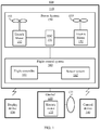
- FIG. 1 is a schematic architecture diagram of an unmanned flight system 100 according to an example embodiment of the present disclosure.
- a rotor-propelled UAV is described for illustrative purposes.
- the unmanned flight system 100 includes a UAV 110, a gimbal 120, a display device 130, and a control device 140.
- the UAV 110 includes a power system 150, a flight control system 160, and a frame.
- the UAV 110 may wirelessly communicate with the control device 140 and the display device 130.
- the frame may include a body and a stand (also called a landing gear).
- the body may include a center frame and one or more arms connected with the center frame. The one or more arms extend radially from the center frame.
- the stand is connected to the body and is configured to support the UAV 110 during landing.
- the power system 150 includes one or more electronic speed controls (referred to as ESC) 151, one or more propellers 153, and one or more electric motors 152 corresponding to the one or more propellers 153.
- the electric motor 152 connects between the ESC 151 and the propeller 153.
- the electric motor 152 and the propeller 153 are disposed at the arm of the UAV 110.
- the ESC 151 is configured to receive a driving signal generated by the flight control system 160 and to supply a driving current to the electric motor 152 according to the driving signal to control a rotation speed of the electric motor 152.
- the electric motor 152 is configured to drive the propeller 153 to rotate to supply power for the flight of the UAV 110. The power enables the UAV 110 to move in one or more degrees of freedom.
- the UAV 110 may rotate around one or more rotation axes.
- the rotation axes may include a roll axis, a yaw axis, and a pitch axis.
- the electric motor 152 may be a direct current (DC) electric motor or an alternate current (AC) electric motor.
- the electric motor 152 may be a brushless motor or a brushed motor.
- the flight control system 160 includes a flight controller 161 and a sensor system 162.
- the sensor system 162 is configured to measure attitude information of the UAV 110, that is, spatial position and state information of the UAV 110, such as three-dimensional position, three-dimensional angle, three-dimensional velocity, three-dimensional acceleration, and three-dimensional angular velocity.
- the sensor system 162 may include, for example, at least one of a gyroscope, an ultrasonic sensor, an electronic compass, an inertial measurement unit (IMU), a visual sensor, a global navigation satellite system, or a barometer.
- the global navigation satellite system may be the global positioning system (GPS).
- the flight controller 161 is configured to control the flight of the UAV 110, for example, to control the flight of the UAV 110 according to the attitude information measured by the sensor system 162. It should be understood that the flight controller 161 may control the UAV 110 according to pre-programmed program instructions or may control the UAV 110 in response to one or more control instructions from the control device 140.
- the gimbal 120 includes an electric motor 122.
- the gimbal 120 is configured to hold a photographing device 123.
- the flight controller 161 may control movement of the gimbal 120 through the electric motor 122.
- the gimbal 120 may also include a controller configured to control the electric motor 122 to control the movement of the gimbal 120.
- the electric motor 122 may be independent of the UAV 110 or may be part of the UAV 110.
- the electric motor 122 may be a DC electric motor or an AC electric motor.
- the electric motor 122 may a brushless electric motor or a brushed electric motor.
- the gimbal 120 may be disposed at the top of the UAV 110 or at the bottom of the UAV 110.
- the photographing device 123 may be, for example, a device for capturing images, such as a camera or camcorder.
- the photographing device 123 may communicate with the flight controller 161 and may capture images under the control of the flight controller 161.
- the photographing device 123 includes at least a photosensitive element, such as a complementary metal oxide semiconductor (CMOS) sensor or a charge-coupled device (CCD) sensor.
- CMOS complementary metal oxide semiconductor
- CCD charge-coupled device
- the display device 130 may communicate with the UAV 110 wirelessly and may be configured to display the attitude information of the UAV 110. In addition, the display device 130 may also display images photographed by the photographing device 123. It should be understood that the display device 130 may be an independent device or may be integrated in the control device 140.
- control device 140 may communicate with the UAV 110 wirelessly and may be configured to remotely control the UAV 110.
- a rotating object may be the electric motor 152 in FIG. 1 .
- FIG. 2 is a flowchart of a rotation parameter detection method according to an example embodiment of the present disclosure. As shown in FIG. 2 , the method includes the following.
- a rotation parameter of the rotating object is obtained based on the detection signal.
- the rotation parameter includes a rotation direction, a rotation speed, a mechanical zero position.
- the obtained rotation parameter includes the rotation direction, the rotation speed, and the mechanical zero position.
- the rotation parameter of the rotating object during the rotation may be detected by an encoder.
- the method according to the embodiments of the present disclosure may be implemented by the encoder.
- the code disc of the encoder rotates with the rotation of the rotating object.
- N fan teeth are disposed at the code disc extending radially, where N is an integer greater than 2.
- Each fan tooth includes a first line segment edge and a second line segment edge. The first line segment edges of the N fan teeth are disposed at the code disc at equal intervals.
- Each fan tooth includes an arc edge along a circumference of the code disc. One of the N fan teeth has the arc edge of a different length. The remaining fan teeth have the arc edges of a same length.
- FIG. 3 is a schematic diagram of a code disc according to an example embodiment of the present disclosure.
- the code disc includes four fan teeth.
- the first line segment edges of the four fan teeth are arranged at the code disc with equal intervals.
- Each fan tooth has the second line segment edge disposed opposite to the first line segment edge.
- One of the four fan teeth is different from the remaining three fan teeth, and has the arc edge length different from that of the remaining three fan teeth.
- one fan tooth has the arc edge length longer than the arc edge lengths of the remaining three fan teeth, and the remaining three fan teeth have the same arc edge lengths.
- the number of the fan teeth of the code disc is not limited to the number of the fan teeth shown in FIG. 3 .
- the fan tooth having the different arc edge length may have the arc edge length shorter than the arc edge lengths of the remaining fan teeth.
- the rotation of the code disc reflects the rotation of the rotating object.
- the rotation of the code disc generates the detection signal.
- the rotation direction, the rotation speed, and the mechanical zero position of the rotating object may be obtained based on the detection signal generated during the rotation of the code disc.
- one of the fan teeth of the code disc is different from other fan teeth, one of the detection signals generated in one complete rotation of the code disc is different.
- the rotation parameter may be obtained through one different detection signal. Compared with the existing technology that needs three detection signals, the number of the detection signals is reduced, the number of supporting hardware is reduced correspondingly, the failure rate is reduced, and the cost is reduced.
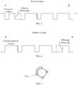
- a photo sensor is disposed adjacent to the code disc. As shown in FIG. 4 , when any of the fan teeth of the code disc blocks the photo sensor, the detection signal is a continuous first signal. When none of the fan teeth of the code disc blocks the photo sensor, the detection signal is a continuous second signal. The first signal is different from the second signal. Thus, when the fan tooth that is different from the other fan teeth blocks the photo sensor, the resulted detection signal is the continuous first signal and a duration of the continuous first signal is longer than the duration of the continuous first signal resulted from being blocked by each of the other fan teeth.
- the first signal is a low-level signal and the second signal is a high-level signal.
- the low-level signal is a 0-level signal and the high-level signal is a 1-level signal.
- the detection signal is a sine wave signal, a cosine wave signal, or a triangle wave signal.
- the detection signal is a square wave signal.
- the code disc if the rotating object rotates clockwise, the code disc also rotates clockwise.
- the code disc rotates one complete round, that is, one rotation period. Because one fan tooth is different from the other fan teeth, when the different fan tooth blocks the photo sensor, the detection signal is the continuous low-level signal having the longest duration, which is preceded by a high-level signal. Because the duration of this low-level signal is the longest, the duration of the preceding high-level signal is the shortest. Compared with the other fan teeth, the preceding high-level signal transitions to the low-level signal ahead of time.
- the code disc if the rotating object rotates counterclockwise, the code disc also rotates counterclockwise.
- the code disc rotates one complete round, that is, one rotation period. Because one fan tooth is different from the other fan teeth, when the different fan tooth blocks the photo sensor, the detection signal is the continuous low-level signal having the longest duration, which is followed by a high-level signal. Because the duration of this low-level signal is the longest, the duration of the succeeding high-level signal is the shortest. Compared with the other fan teeth, this low-level signal transitions to the high-level signal behind in time.
- the rotation parameter of the rotating object may be detected.
- the rotation direction is determined based on a rising edge and/or a falling edge of the detection signal. For example, as shown in FIG. 5 and FIG. 6 , the rising edge of the detection signal generated when the rotating object rotates clockwise is different from the rising edge of the detection signal generated when the rotating object rotates counterclockwise. Similarly, the falling edge of the detection signal generated when the rotating object rotates clockwise is different from the falling edge of the detection signal generated when the rotating object rotates counterclockwise. Thus, the rotation direction may be determined based on the rising edges and/or the falling edges of the detection signal in the rotation period.
- the rotation direction is determined based on time relationship between the rising edges in the detection signal and/or time relationship between the falling edges in the detection signal. For example, as shown in FIG. 5 and FIG. 6 , the rising edges in the detection signal detected during the clockwise rotation are different in time from the rising edges in the detection signal detected during the counterclockwise rotation, and the falling edges in the detection signal detected during the clockwise rotation are different in time from the falling edges in the detection signal detected during the counterclockwise rotation.
- the rotation direction may be determined based on the time relationship between the rising edges in the detection signal detected in the rotation period and/or the time relationship between the falling edges in the detection signal detected in the rotation period.
- any two adjacent rising edges in the detection signal are equally separated in time in the rotation period, and any two adjacent falling edges in the detection signal are not always equally separated in time in the rotation period.
- the time difference between the first falling edge and the second falling edge is smaller than the time difference between the second falling edge and the third falling edge.
- the detection signal is detected during the counterclockwise rotation, as shown in FIG. 6 , any two adjacent falling edges in the detection signal are equally separated in time in the rotation period, and any two adjacent rising edges in the detection signal are not always equally separated in time in the rotation period.
- the time difference between the third rising edge and the fourth rising edge is greater than the time difference between the fourth rising edge and the fifth rising edge.
- the rotation direction is determined to be clockwise.
- the rotation direction is determined to be counterclockwise.
- the rotation direction when any two adjacent falling edges in the detection signal are not always equally separated in time in the rotation period, the rotation direction is determined to be clockwise. When any two adjacent rising edges in the detection signal are not always equally separated in time in the rotation period, the rotation direction is determined to be counterclockwise. As such, in one rotation period, when the time difference between the adjacent falling edges in the detection signal are detected to be different or the time difference between the adjacent rising edges in the detection signal are detected to be different, the rotation direction may be accurately determined. It is not necessary to obtain the time differences between all adjacent falling edges or the time differences between all adjacent rising edges. Thus, the rotation direction is determined more quickly and determining the rotation direction is more efficient.
- any two adjacent falling edges in the detection signal are equally separated in time in the rotation period, and any two adjacent rising edges in the detection signal are not always equally separated in time in the rotation period.
- the time difference between the third rising edge and the fourth rising edge is greater than the time difference between the fourth rising edge and the fifth rising edge.
- the detection signal is detected during the counterclockwise rotation, as shown in FIG. 9 , any two adjacent rising edges in the detection signal are equally separated in time in the rotation period, and any two adjacent falling edges in the detection signal are not always equally separated in time in the rotation period.
- the time difference between the first falling edge and the second falling edge is smaller than the time difference between the second falling edge and the third falling edge.
- the rotation direction is determined to be clockwise.
- the rotation direction is determined to be counterclockwise.
- the rotation direction when any two adjacent rising edges in the detection signal are not always equally separated in time in the rotation period, the rotation direction is determined to be clockwise. When any two adjacent falling edges in the detection signal are not always equally separated in time in the rotation period, the rotation direction is determined to be counterclockwise. As such, in one rotation period, when the time difference between the adjacent falling edges in the detection signal are detected to be different or the time difference between the adjacent rising edges in the detection signal are detected to be different, the rotation direction may be accurately determined. It is not necessary to obtain the time differences between all adjacent falling edges or the time differences between all adjacent rising edges. Thus, the rotation direction is determined more quickly and determining the rotation direction is more efficient.
- a duration of the detection signal is obtained. Then, based on the duration, the rotation speed is determined. In this case, the rotating object rotates one complete round.
- the code disc also rotates one complete round.
- the duration of one complete round of the rotation of the code disc is obtained. Based on the duration for one complete round of the rotation, the rotation speed may be determined. For example, the rotation speed is determined to be 1/T, where T is the duration for one complete round of the rotation.
- the rotation speed is determined based on the time relationship between the rising edges in the detection signal and/or the time relationship between the falling edges in the detection signal.
- the rotation speed of the rotating object determines the rotation speed of the code disc and timing of the rising and falling edges in the detection signal. For example, the faster the rotation speed of the rotating object, the shorter the time difference between the rising edges and between the falling edges. The slower the rotation speed of the rotating object, the longer the time difference between the rising edges and between the falling edges.
- the rotation direction may be determined based on the time relationship between the rising edges in the detection signal and/or the time relationship between the falling edges in the detection signal. Two implementation solutions are illustrated below, but the present disclosure is not limited thereto.
- time differences between each and every two adjacent rising edges in the detection signal in the rotation period are obtained.
- N time differences are obtained.
- an average time difference is obtained.
- the rotation speed is obtained.
- the time differences between each and every two adjacent falling edges in the detection signal in the rotation period are obtained.
- N time differences are obtained.
- an average time difference is obtained.
- the rotation speed is obtained. For example, as shown in FIG. 5, FIG. 6 , FIG. 8, and FIG. 9 , the average time difference obtained from the time differences between each and every two adjacent rising edges in the rotation period is the same as the average time difference obtained from the time differences between each and every two adjacent falling edges in the rotation period.
- the average time difference finally obtained is the same. Because the fan teeth divide the code disc into N segments, it takes the average time difference for the code disc to rotate 1/N of the complete round, and as such, the rotation speed may be determined. For example, the rotation speed is 1/(N * t), where t is the average time difference.
- the rotation speed is determined based on the time difference between any two adjacent rising edges in the detection signal in the rotation period. As shown in FIG. 5 or FIG. 9 , any two adjacent rising edges in the detection signal are equally separated in time in the rotation period, and the time difference between any two rising edges is equal to the rotation period divided by N. Thus, the rotation speed may be quickly determined based on the time difference between any two adjacent rising edges. It is not necessary to wait for one rotation period. Thus, the rotation speed is determined more quickly and determining the rotation speed is more efficient.
- the rotation speed is determined based on the time difference between any two adjacent falling edges in the detection signal in the rotation period. As shown in FIG. 6 or FIG. 8 , any two adjacent falling edges in the detection signal are equally separated in time in the rotation period, and the time difference between any two falling edges is equal to the rotation period divided by N. Thus, the rotation speed may be quickly determined based on the time difference between any two adjacent falling edges. It is not necessary to wait for one rotation period. Thus, the rotation speed is determined more quickly and determining the rotation speed is more efficient.
- a mechanical zero position is obtained based on the rising edges and/or the falling edges in the detection signal.
- the detection signal generated during the clockwise rotation of the rotating object includes one rising edge different from the other rising edges in the rotation period and the detection signal generated during the counterclockwise rotation of the rotating object includes one falling edge different from the other falling edges in the rotation period.
- the rotation direction may be determined based on the rising edges and/or the falling edges in the detection signal in the rotation period.
- a reference rising edge is determined based on the time relationship between the rising edges in the detection signal in the rotation period. Then, based on the time point of the reference rising edge, the mechanical zero position is determined.
- the time difference between the reference rising edge and the rising edge preceding the reference rising edge is not equal to the time difference between the reference rising edge and the rising edge succeeding the reference rising edge.
- the time difference between the third rising edge and the fourth rising edge is greater than the time difference between the fourth rising edge and the fifth rising edge.
- the fourth rising edge is the reference rising edge.
- the mechanical zero position is determined. For example, the time point of the reference rising edge is determined to be the mechanical zero position. Or a time point that is a pre-set time interval away from the time point of the reference rising edge is determined to be the mechanical zero position.
- a reference falling edge is determined based on the time relationship between the falling edges in the detection signal in the rotation period. Then, based on the time point of the reference falling edge, the mechanical zero position is determined.
- the time difference between the reference falling edge and the falling edge preceding the reference falling edge is not equal to the time difference between the reference falling edge and the falling edge succeeding the reference falling edge.
- the time difference between the first falling edge and the second falling edge is smaller than the time difference between the second falling edge and the third falling edge.
- the second falling edge is the reference falling edge.
- the mechanical zero position is determined. For example, the time point of the reference falling edge is determined to be the mechanical zero position. Or a time point that is a pre-set time interval away from the time point of the reference falling edge is determined to be the mechanical zero position.
- the rotation direction, the rotation speed, and the mechanical zero position may be obtained through one detection signal.
- the number of the detection signals is reduced, the number of supporting hardware is reduced correspondingly, the failure rate is reduced, and the cost is reduced.
- the present disclosure also provides a computer storage medium.
- the computer storage medium stores program instructions. When being executed, the program is configured to perform some or all of the processes of the rotation parameter detection method in FIG. 2 and the corresponding embodiments.
- FIG. 10 is a structural block diagram of an encoder according to an example embodiment of the present disclosure.
- the encoder 300 includes a code disc 301 and a processor 302.
- the processor 302 is communicatively coupled with the code disc 301.
- the code disc 301 rotates with the rotation of the rotating object.
- the processor 302 may be a central processing unit (CPU).
- the processor 302 may also be other general-purpose processor, a digital signal processor (DSP), an application specific integrated circuit (ASIC), a field-programmable gate array (FPGA) or other programmable logic device, discrete gate or transistor logic device, or discrete hardware component.
- DSP digital signal processor
- ASIC application specific integrated circuit
- FPGA field-programmable gate array
- the general-purpose processor may be a microprocessor or any conventional processor.
- the processor 302 is configured to detect the rotation of the code disc 301 to obtain a detection signal and to obtain the rotation parameter of the rotating object based on the detection signal.
- the rotation parameter includes the rotation direction, the rotation speed, and the mechanical zero position.
- N fan teeth are disposed at the code disc 301 extending radially, where N is an integer greater than 2.
- Each fan tooth includes a first line segment edge and a second line segment edge.
- the first line segment edges of the N fan teeth are disposed at the code disc 301 at equal intervals.
- Each fan tooth includes an arc edge along a circumference of the code disc 301.
- One of the N fan teeth has the arc edge of a different length.
- the other N-1 fan teeth have the arc edges of a same length.
- the code disc 301 is illustrated in FIG. 3 .
- the encoder is configured to implement the technical solutions of the foregoing method embodiments.
- the operation principle and the technical effects are similar and will not be repeated herein.
- FIG. 11 is a structural block diagram of the encoder according to another example embodiment of the present disclosure. As shown in FIG. 11 , in addition to the embodiment in FIG. 10 , the encoder 300 further includes a photo sensor303. The photo sensor 303 is communicatively coupled with the processor 302.
- the detection signal is a continuous first signal.
- the detection signal is a continuous second signal. The first signal is different from the second signal.
- the first signal is a low-level signal and the second signal is a high-level signal.
- the detection signal is a square wave signal.
- the processor 302 is configured to determine the rotation direction based on the rising edges and/or the falling edges in the detection signal in the rotation period of the rotating object.
- the processor 302 is configured to determine the rotation direction based on the time relationship between the rising edges in the detection signal and/or the time relationship between the falling edges in the detection signal in the rotation period of the rotating object.
- the processor 302 is configured to perform the following.
- the rotation direction is determined to be counterclockwise.
- the rotation direction is determined to be clockwise.
- the rotation direction is determined to be clockwise.
- the rotation direction is determined to be counterclockwise.
- the processor 302 is configured to: obtain a duration of the detection signal during the rotation period of the rotating object, and determine the rotation speed based on the duration.
- the processor 302 is configured to: determine the rotation speed based on the time relationship between the rising edges in the detection signal and/or the time relationship between the falling edges in the detection signal during the rotation period of the rotating object.
- the processor 302 is configured to: obtain the time difference between each and every two adjacent rising edges in the detection signal in the rotation period or the time difference between each and every two adjacent falling edges in the detection signal in the rotation period, obtain the average time difference based on N time differences, and determine the rotation speed based on the average time difference.
- the processor 302 is configured to: determine the rotation speed based on the time difference between any two adjacent rising edges in the detection signal in the rotation period when any two adjacent rising edges in the detection signal are equally separated in time in the rotation period, or determine the rotation speed based on the time difference between any two adjacent falling edges in the detection signal in the rotation period when any two adjacent falling edges in the detection signal are equally separated in time in the rotation period.
- the processor 302 is configured to: determine the mechanical zero position based on the rising edges and/or the falling edges in the in the detection signal in the rotation period of the rotating object.
- the processor 302 is configured to: determine a reference rising edge based on the time relationship between the rising edges in the detection signal in the rotation period when any two adjacent rising edges in the detection signal are not always equally separated in time in the rotation period and determine the mechanical zero position based on the time point of the reference rising edge, where the time difference between the reference rising edge and the rising edge preceding the reference rising edge is not equal to the time difference between the reference rising edge and the rising edge succeeding the reference rising edge.
- the processor 302 is configured to: determine a reference falling edge based on the time relationship between the falling edges in the detection signal in the rotation period when any two adjacent falling edges in the detection signal are not always equally separated in time in the rotation period and determine the mechanical zero position based on the time point of the reference falling edge, where the time difference between the reference falling edge and the falling edge preceding the reference falling edge is not equal to the time difference between the reference falling edge and the falling edge succeeding the reference falling edge.
- the rotating object is an electric motor.
- the encoder also includes a memory 304.
- the processor 302 is connected to the memory 304 through a bus.
- the memory 304 may include a read-only memory (ROM) and a random-access memory (RAM), and may provide instructions and data to the processor 302.
- a part of the memory 304 may also include a non-volatile random-access memory.
- the memory 304 is configured to store the code for implementing the rotation parameter detection method.
- the processor 302 is configured to invoke the code stored in the memory 304 to execute the foregoing solution.
- the encoder is configured to implement the technical solutions of the foregoing method embodiments.
- the operation principle and the technical effects are similar and will not be repeated herein.
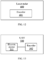
- FIG. 12 is a structural block diagram of a laser radar according to an example embodiment of the present disclosure.
- the laser radar 400 includes an encoder 401.
- the encoder 401 may be implemented by using the device shown in FIG. 10 or FIG. 11 .
- the encoder 401 is configured to implement the technical solutions of the foregoing method embodiments. The operation principle and the technical effects are similar and will not be repeated herein.
- the laser radar 400 also includes other components, which are not shown here.
- FIG. 13 is a structural block diagram of an unmanned aerial vehicle according to an example embodiment of the present disclosure.
- the unmanned aerial vehicle (UAV) 500 includes an electric motor 501 and an encoder 502.
- the encoder 502 is configured to detect the rotation parameter of the electric motor 501.
- the encoder 502 may be implemented by using the device shown in FIG. 10 or FIG. 11 .
- the encoder 501 is configured to implement the technical solutions of the foregoing method embodiments. The operation principle and the technical effects are similar and will not be repeated herein.
- the UAV 500 also includes other components, which are not shown here.
- the program may be stored in a computer-readable storage medium.
- the storage medium includes any medium for storing the program instructions, such as a read-only memory (ROM), a random-access memory (RAM), a magnetic disk, or an optical disk.
Landscapes
- Physics & Mathematics (AREA)
- General Physics & Mathematics (AREA)
- Engineering & Computer Science (AREA)
- Electromagnetism (AREA)
- Power Engineering (AREA)
- Computer Networks & Wireless Communication (AREA)
- Radar, Positioning & Navigation (AREA)
- Remote Sensing (AREA)
- Optical Transform (AREA)
- Indicating Or Recording The Presence, Absence, Or Direction Of Movement (AREA)
- Transmission And Conversion Of Sensor Element Output (AREA)
Abstract
Description
- The present disclosure relates to the technical field of encoders and, more particularly, to a rotation parameter detection method, an encoder, a laser radar, and an unmanned aerial vehicle.
- An electric motor is an important component of an unmanned aerial vehicle (UAV). Taking the UAV being an unmanned aircraft as an example, the electric motor drives a propeller on the unmanned aircraft to rotate to fly the unmanned aircraft. A rotation direction of the electric motor affects a flying direction of the unmanned aircraft and a rotation speed of the electric motor affects a flying speed of the unmanned aircraft. To precisely control flight of the unmanned aircraft, rotation parameters of the electric motor, such as the rotation speed, the rotation direction, and a rotation time, need to be detected. Currently, ABZ signals are used to detect the rotation parameters. Specifically, the rotation speed and the rotation direction of the electric motor are recognized based on an A signal and a B signal, a mechanical zero position is recognized based on a Z signal. However, the A signal, the B signal, and the Z signal are obtained by three sensors, respectively. The three sensors are controlled by three hardware switches, respectively. Each hardware switch has a corresponding failure rate. As long as one of the three hardware switches fails, it is unable to obtain the rotation parameters. Thus, using the ABZ signals to detect the rotation parameters has a high failure rate and correspondingly, the cost is high.
- The present disclosure provides a rotation parameter detection method, an encoder, a laser radar, and an unmanned aerial vehicle, configured to obtain a rotation parameter through a detection signal to reduce cost.
- In accordance with the disclosure, there is provided a rotation parameter detection method comprising: detecting rotation of a code disc to obtain a detection signal, wherein the code disc rotates with the rotation of a rotating object; and based on the detection signal, obtaining a rotation parameter of the rotating object, wherein the rotation parameter includes a rotation direction, a rotation speed, a mechanical zero position. N fan teeth are disposed at the code disc extending radially, N being an integer greater than 2. Each fan tooth includes a first line segment edge and a second line segment edge. The first line segment edges of the N fan teeth are arranged at the code disc with equal intervals. One of the N fan teeth has an arc edge length along a circumference of the code disc different from that of the remaining N-1 fan teeth and the remaining N-1 fan teeth have the same arc edge lengths.
- Also in accordance with the disclosure, there is provided an encoder comprising: a code disc that rotates with rotation of a rotating object; and a processor communicatively coupled with the code disc. The processor is configured to detect the rotation of the code disc to obtain a detection signal, and to obtain a rotation parameter of the rotating object based on the detection signal. The rotation parameter includes a rotation direction, a rotation speed, a mechanical zero position. N fan teeth are disposed at the code disc extending radially, N being an integer greater than 2. Each fan tooth includes a first line segment edge and a second line segment edge. The first line segment edges of the N fan teeth are arranged at the code disc with equal intervals. One of the N fan teeth has an arc edge length along a circumference of the code disc different from that of the remaining N-1 fan teeth and the remaining N-1 fan teeth have the same arc edge lengths.
- Also in accordance with the disclosure, there is provided a laser radar comprising the disclosed encoder.
- Also in accordance with the disclosure, there is provided an unmanned aerial vehicle comprising: an electric motor; and the disclosed encoder. The encoder is configured to detect the rotation parameter of the electric motor.
- Also in accordance with the disclosure, there is provided a computer-readable storage medium. The computer-readable storage medium stores a computer program. When the computer program is executed, the computer program implements the disclosed rotation parameter detection method.
- The rotation parameter detection method, the encoder, the laser radar, and the unmanned aerial vehicle are provided. The method includes: detecting rotation of a code disc to obtain a detection signal, and based on the detection signal, obtaining a rotation parameter of the rotating object. Because the code disc is driven by the rotating object to rotate, the rotation of the code disc reflects the rotation of the rotating object. The rotation of the code disc generates the detection signal. The rotation direction, the rotation speed, and the mechanical zero position of the rotating object may be obtained based on the detection signal generated during the rotation of the code disc. Because one of fan teeth of the code disc is different from other fan teeth, one of the detection signals generated in one complete rotation of the code disc is different. As such, the rotation parameter may be obtained through one different detection signal. Compared with the existing technology that needs three detection signals, the number of the detection signals is reduced, the number of supporting hardware is reduced correspondingly, the failure rate is reduced, and the cost is reduced.
- To more clearly illustrate the technical solution of the present disclosure, the accompanying drawings used in the description of the disclosed embodiments are briefly described hereinafter. The drawings described below are merely some embodiments of the present disclosure. Other drawings may be derived from such drawings by a person with ordinary skill in the art without creative efforts and may be encompassed in the present disclosure.
-
FIG. 1 is a schematic architecture diagram of anunmanned flight system 100 according to an example embodiment of the present disclosure. -
FIG. 2 is a flowchart of a rotation parameter detection method according to an example embodiment of the present disclosure. -
FIG. 3 is a schematic diagram of a code disc according to an example embodiment of the present disclosure. -
FIG. 4 is a schematic diagram of the code disc and an optoelectrical sensor according to an example embodiment of the present disclosure. -
FIG. 5 is a schematic waveform diagram of a detection signal of a clockwise rotating code disc according to an example embodiment of the present disclosure. -
FIG. 6 is a schematic waveform diagram of a detection signal of a counterclockwise rotating code disc according to an example embodiment of the present disclosure. -
FIG. 7 is a schematic diagram of the code disc and the optoelectrical sensor according to another example embodiment of the present disclosure. -
FIG. 8 is a schematic waveform diagram of the detection signal of the clockwise rotating code disc according to another example embodiment of the present disclosure. -
FIG. 9 is a schematic waveform diagram of the detection signal of the counterclockwise rotating code disc according to another example embodiment of the present disclosure. -
FIG. 10 is a structural block diagram of an encoder according to an example embodiment of the present disclosure. -
FIG. 11 is a structural block diagram of the encoder according to another example embodiment of the present disclosure. -
FIG. 12 is a structural block diagram of a laser radar according to an example embodiment of the present disclosure. -
FIG. 13 is a structural block diagram of an unmanned aerial vehicle according to an example embodiment of the present disclosure. - To make the objectives, technical solutions, and advantages of the embodiments of the present disclosure clearer, technical solutions of the present disclosure will be clearly and completely described with reference to the drawings. It will be appreciated that the described embodiments are some rather than all of the embodiments of the present disclosure. Other embodiments conceived by those having ordinary skills in the art on the basis of the described embodiments without inventive efforts should fall within the scope of the present disclosure.
- The embodiments of the present disclosure provide a rotation parameter detection method, an encoder, a laser radar, and an unmanned aerial vehicle (UAV). The UAV may be, but is not limited to, a rotorcraft, for example, a multi-rotor aircraft propelled by a plurality of air propulsion devices.
-
FIG. 1 is a schematic architecture diagram of anunmanned flight system 100 according to an example embodiment of the present disclosure. In the embodiments of the present disclosure, a rotor-propelled UAV is described for illustrative purposes. - The
unmanned flight system 100 includes aUAV 110, agimbal 120, adisplay device 130, and a control device 140. TheUAV 110 includes apower system 150, aflight control system 160, and a frame. TheUAV 110 may wirelessly communicate with the control device 140 and thedisplay device 130. - The frame may include a body and a stand (also called a landing gear). The body may include a center frame and one or more arms connected with the center frame. The one or more arms extend radially from the center frame. The stand is connected to the body and is configured to support the
UAV 110 during landing. - The
power system 150 includes one or more electronic speed controls (referred to as ESC) 151, one ormore propellers 153, and one or moreelectric motors 152 corresponding to the one ormore propellers 153. Theelectric motor 152 connects between theESC 151 and thepropeller 153. Theelectric motor 152 and thepropeller 153 are disposed at the arm of theUAV 110. TheESC 151 is configured to receive a driving signal generated by theflight control system 160 and to supply a driving current to theelectric motor 152 according to the driving signal to control a rotation speed of theelectric motor 152. Theelectric motor 152 is configured to drive thepropeller 153 to rotate to supply power for the flight of theUAV 110. The power enables theUAV 110 to move in one or more degrees of freedom. In some embodiments, theUAV 110 may rotate around one or more rotation axes. For example, the rotation axes may include a roll axis, a yaw axis, and a pitch axis. It should be understood that theelectric motor 152 may be a direct current (DC) electric motor or an alternate current (AC) electric motor. In addition, theelectric motor 152 may be a brushless motor or a brushed motor. - The
flight control system 160 includes aflight controller 161 and asensor system 162. Thesensor system 162 is configured to measure attitude information of theUAV 110, that is, spatial position and state information of theUAV 110, such as three-dimensional position, three-dimensional angle, three-dimensional velocity, three-dimensional acceleration, and three-dimensional angular velocity. Thesensor system 162 may include, for example, at least one of a gyroscope, an ultrasonic sensor, an electronic compass, an inertial measurement unit (IMU), a visual sensor, a global navigation satellite system, or a barometer. For example, the global navigation satellite system may be the global positioning system (GPS). Theflight controller 161 is configured to control the flight of theUAV 110, for example, to control the flight of theUAV 110 according to the attitude information measured by thesensor system 162. It should be understood that theflight controller 161 may control theUAV 110 according to pre-programmed program instructions or may control theUAV 110 in response to one or more control instructions from the control device 140. - The
gimbal 120 includes anelectric motor 122. Thegimbal 120 is configured to hold a photographingdevice 123. Theflight controller 161 may control movement of thegimbal 120 through theelectric motor 122. In one embodiment, thegimbal 120 may also include a controller configured to control theelectric motor 122 to control the movement of thegimbal 120. It should be understood that theelectric motor 122 may be independent of theUAV 110 or may be part of theUAV 110. It should be understood that theelectric motor 122 may be a DC electric motor or an AC electric motor. In addition, theelectric motor 122 may a brushless electric motor or a brushed electric motor. It should be understood that thegimbal 120 may be disposed at the top of theUAV 110 or at the bottom of theUAV 110. - The photographing
device 123 may be, for example, a device for capturing images, such as a camera or camcorder. The photographingdevice 123 may communicate with theflight controller 161 and may capture images under the control of theflight controller 161. In one embodiment, the photographingdevice 123 includes at least a photosensitive element, such as a complementary metal oxide semiconductor (CMOS) sensor or a charge-coupled device (CCD) sensor. - Disposed at a ground terminal of the
unmanned flight system 100, thedisplay device 130 may communicate with theUAV 110 wirelessly and may be configured to display the attitude information of theUAV 110. In addition, thedisplay device 130 may also display images photographed by the photographingdevice 123. It should be understood that thedisplay device 130 may be an independent device or may be integrated in the control device 140. - Disposed at the ground terminal of the
unmanned flight system 100, the control device 140 may communicate with theUAV 110 wirelessly and may be configured to remotely control theUAV 110. - It should be understood that the foregoing naming of various components of the
unmanned flight system 100 is merely for identification purpose, and should not be construed as limiting the embodiments of the present disclosure. - In the embodiments of the present disclosure, a rotating object may be the
electric motor 152 inFIG. 1 . -
FIG. 2 is a flowchart of a rotation parameter detection method according to an example embodiment of the present disclosure. As shown inFIG. 2 , the method includes the following. - At S201, rotation of a code disc is detected to obtain a detection signal. The code disc rotates with the rotation of the rotating object.
- At S202, a rotation parameter of the rotating object is obtained based on the detection signal. The rotation parameter includes a rotation direction, a rotation speed, a mechanical zero position.
- In some embodiments, the obtained rotation parameter includes the rotation direction, the rotation speed, and the mechanical zero position. The rotation parameter of the rotating object during the rotation may be detected by an encoder. Thus, the method according to the embodiments of the present disclosure may be implemented by the encoder. The code disc of the encoder rotates with the rotation of the rotating object.
- In some embodiments, N fan teeth are disposed at the code disc extending radially, where N is an integer greater than 2. Each fan tooth includes a first line segment edge and a second line segment edge. The first line segment edges of the N fan teeth are disposed at the code disc at equal intervals. Each fan tooth includes an arc edge along a circumference of the code disc. One of the N fan teeth has the arc edge of a different length. The remaining fan teeth have the arc edges of a same length.
-
FIG. 3 is a schematic diagram of a code disc according to an example embodiment of the present disclosure. As shown inFIG. 3 , the code disc includes four fan teeth. The first line segment edges of the four fan teeth are arranged at the code disc with equal intervals. Each fan tooth has the second line segment edge disposed opposite to the first line segment edge. One of the four fan teeth is different from the remaining three fan teeth, and has the arc edge length different from that of the remaining three fan teeth. As shown inFIG. 3 , one fan tooth has the arc edge length longer than the arc edge lengths of the remaining three fan teeth, and the remaining three fan teeth have the same arc edge lengths. It should be noted that the number of the fan teeth of the code disc is not limited to the number of the fan teeth shown inFIG. 3 . In some embodiments, the fan tooth having the different arc edge length may have the arc edge length shorter than the arc edge lengths of the remaining fan teeth. - Because the code disc is driven by the rotating object to rotate, the rotation of the code disc reflects the rotation of the rotating object. The rotation of the code disc generates the detection signal. The rotation direction, the rotation speed, and the mechanical zero position of the rotating object may be obtained based on the detection signal generated during the rotation of the code disc. Because one of the fan teeth of the code disc is different from other fan teeth, one of the detection signals generated in one complete rotation of the code disc is different. As such, in one embodiment, the rotation parameter may be obtained through one different detection signal. Compared with the existing technology that needs three detection signals, the number of the detection signals is reduced, the number of supporting hardware is reduced correspondingly, the failure rate is reduced, and the cost is reduced.
- In some embodiments, a photo sensor is disposed adjacent to the code disc. As shown in
FIG. 4 , when any of the fan teeth of the code disc blocks the photo sensor, the detection signal is a continuous first signal. When none of the fan teeth of the code disc blocks the photo sensor, the detection signal is a continuous second signal. The first signal is different from the second signal. Thus, when the fan tooth that is different from the other fan teeth blocks the photo sensor, the resulted detection signal is the continuous first signal and a duration of the continuous first signal is longer than the duration of the continuous first signal resulted from being blocked by each of the other fan teeth. - In some embodiments, the first signal is a low-level signal and the second signal is a high-level signal. For example, the low-level signal is a 0-level signal and the high-level signal is a 1-level signal.
- In some embodiments, the detection signal is a sine wave signal, a cosine wave signal, or a triangle wave signal.
- In some embodiments, the detection signal is a square wave signal.
- Referring to
FIG. 4 andFIG. 5 , if the rotating object rotates clockwise, the code disc also rotates clockwise. The code disc rotates one complete round, that is, one rotation period. Because one fan tooth is different from the other fan teeth, when the different fan tooth blocks the photo sensor, the detection signal is the continuous low-level signal having the longest duration, which is preceded by a high-level signal. Because the duration of this low-level signal is the longest, the duration of the preceding high-level signal is the shortest. Compared with the other fan teeth, the preceding high-level signal transitions to the low-level signal ahead of time. - Referring to
FIG. 4 andFIG. 6 , if the rotating object rotates counterclockwise, the code disc also rotates counterclockwise. The code disc rotates one complete round, that is, one rotation period. Because one fan tooth is different from the other fan teeth, when the different fan tooth blocks the photo sensor, the detection signal is the continuous low-level signal having the longest duration, which is followed by a high-level signal. Because the duration of this low-level signal is the longest, the duration of the succeeding high-level signal is the shortest. Compared with the other fan teeth, this low-level signal transitions to the high-level signal behind in time. - Based on the waveform of the detection signal in the rotation period in
FIG. 5 or FIG. 6 , the rotation parameter of the rotating object may be detected. - The following describes how to obtain the rotation direction in the rotation parameter.
- In some embodiments, during the rotation period of the rotating object, the rotation direction is determined based on a rising edge and/or a falling edge of the detection signal. For example, as shown in
FIG. 5 and FIG. 6 , the rising edge of the detection signal generated when the rotating object rotates clockwise is different from the rising edge of the detection signal generated when the rotating object rotates counterclockwise. Similarly, the falling edge of the detection signal generated when the rotating object rotates clockwise is different from the falling edge of the detection signal generated when the rotating object rotates counterclockwise. Thus, the rotation direction may be determined based on the rising edges and/or the falling edges of the detection signal in the rotation period. - In one embodiment, in the rotation period of the rotating object, the rotation direction is determined based on time relationship between the rising edges in the detection signal and/or time relationship between the falling edges in the detection signal. For example, as shown in
FIG. 5 and FIG. 6 , the rising edges in the detection signal detected during the clockwise rotation are different in time from the rising edges in the detection signal detected during the counterclockwise rotation, and the falling edges in the detection signal detected during the clockwise rotation are different in time from the falling edges in the detection signal detected during the counterclockwise rotation. Thus, the rotation direction may be determined based on the time relationship between the rising edges in the detection signal detected in the rotation period and/or the time relationship between the falling edges in the detection signal detected in the rotation period. - If the first line segment edge is disposed in the counterclockwise direction of the fan tooth, for example, as shown in
FIG. 4 , and the detection signal is detected during the clockwise rotation, as shown inFIG. 5 , any two adjacent rising edges in the detection signal are equally separated in time in the rotation period, and any two adjacent falling edges in the detection signal are not always equally separated in time in the rotation period. As shown inFIG. 5 , the time difference between the first falling edge and the second falling edge is smaller than the time difference between the second falling edge and the third falling edge. When the detection signal is detected during the counterclockwise rotation, as shown inFIG. 6 , any two adjacent falling edges in the detection signal are equally separated in time in the rotation period, and any two adjacent rising edges in the detection signal are not always equally separated in time in the rotation period. As shown inFIG. 6 , the time difference between the third rising edge and the fourth rising edge is greater than the time difference between the fourth rising edge and the fifth rising edge. - Therefore, in one embodiment, when any two adjacent rising edges in the detection signal are equally separated in time in the rotation period, the rotation direction is determined to be clockwise. When any two adjacent falling edges in the detection signal are equally separated in time in the rotation period, the rotation direction is determined to be counterclockwise.
- In another embodiment, when any two adjacent falling edges in the detection signal are not always equally separated in time in the rotation period, the rotation direction is determined to be clockwise. When any two adjacent rising edges in the detection signal are not always equally separated in time in the rotation period, the rotation direction is determined to be counterclockwise. As such, in one rotation period, when the time difference between the adjacent falling edges in the detection signal are detected to be different or the time difference between the adjacent rising edges in the detection signal are detected to be different, the rotation direction may be accurately determined. It is not necessary to obtain the time differences between all adjacent falling edges or the time differences between all adjacent rising edges. Thus, the rotation direction is determined more quickly and determining the rotation direction is more efficient.
- If the first line segment edge is disposed in the clockwise direction of the fan tooth, for example, as shown in
FIG. 7 , and the detection signal is detected during the clockwise rotation, as shown inFIG. 8 , any two adjacent falling edges in the detection signal are equally separated in time in the rotation period, and any two adjacent rising edges in the detection signal are not always equally separated in time in the rotation period. As shown inFIG. 8 , the time difference between the third rising edge and the fourth rising edge is greater than the time difference between the fourth rising edge and the fifth rising edge. When the detection signal is detected during the counterclockwise rotation, as shown inFIG. 9 , any two adjacent rising edges in the detection signal are equally separated in time in the rotation period, and any two adjacent falling edges in the detection signal are not always equally separated in time in the rotation period. As shown inFIG. 9 , the time difference between the first falling edge and the second falling edge is smaller than the time difference between the second falling edge and the third falling edge. - Therefore, in one embodiment, when any two adjacent falling edges in the detection signal are equally separated in time in the rotation period, the rotation direction is determined to be clockwise. When any two adjacent rising edges in the detection signal are equally separated in time in the rotation period, the rotation direction is determined to be counterclockwise.
- In another embodiment, when any two adjacent rising edges in the detection signal are not always equally separated in time in the rotation period, the rotation direction is determined to be clockwise. When any two adjacent falling edges in the detection signal are not always equally separated in time in the rotation period, the rotation direction is determined to be counterclockwise. As such, in one rotation period, when the time difference between the adjacent falling edges in the detection signal are detected to be different or the time difference between the adjacent rising edges in the detection signal are detected to be different, the rotation direction may be accurately determined. It is not necessary to obtain the time differences between all adjacent falling edges or the time differences between all adjacent rising edges. Thus, the rotation direction is determined more quickly and determining the rotation direction is more efficient.
- The following describes how to obtain the rotation speed in the rotation parameter.
- In one embodiment, during the rotation period of the rotating object, a duration of the detection signal is obtained. Then, based on the duration, the rotation speed is determined. In this case, the rotating object rotates one complete round. Correspondingly, the code disc also rotates one complete round. The duration of one complete round of the rotation of the code disc is obtained. Based on the duration for one complete round of the rotation, the rotation speed may be determined. For example, the rotation speed is determined to be 1/T, where T is the duration for one complete round of the rotation.
- In one embodiment, during the rotation period of the rotating object, the rotation speed is determined based on the time relationship between the rising edges in the detection signal and/or the time relationship between the falling edges in the detection signal. The rotation speed of the rotating object determines the rotation speed of the code disc and timing of the rising and falling edges in the detection signal. For example, the faster the rotation speed of the rotating object, the shorter the time difference between the rising edges and between the falling edges. The slower the rotation speed of the rotating object, the longer the time difference between the rising edges and between the falling edges. Thus, the rotation direction may be determined based on the time relationship between the rising edges in the detection signal and/or the time relationship between the falling edges in the detection signal. Two implementation solutions are illustrated below, but the present disclosure is not limited thereto.
- In one embodiment, time differences between each and every two adjacent rising edges in the detection signal in the rotation period are obtained. N time differences are obtained. Based on the N time differences, an average time difference is obtained. Based on the average time difference, the rotation speed is obtained. In another embodiment, the time differences between each and every two adjacent falling edges in the detection signal in the rotation period are obtained. N time differences are obtained. Based on the N time differences, an average time difference is obtained. Based on the average time difference, the rotation speed is obtained. For example, as shown in
FIG. 5, FIG. 6 ,FIG. 8, and FIG. 9 , the average time difference obtained from the time differences between each and every two adjacent rising edges in the rotation period is the same as the average time difference obtained from the time differences between each and every two adjacent falling edges in the rotation period. Thus, regardless of the rising edges or the falling edges, the average time difference finally obtained is the same. Because the fan teeth divide the code disc into N segments, it takes the average time difference for the code disc to rotate 1/N of the complete round, and as such, the rotation speed may be determined. For example, the rotation speed is 1/(N * t), where t is the average time difference. - In another embodiment, when any two adjacent rising edges in the detection signal are equally separated in time in the rotation period, the rotation speed is determined based on the time difference between any two adjacent rising edges in the detection signal in the rotation period. As shown in
FIG. 5 orFIG. 9 , any two adjacent rising edges in the detection signal are equally separated in time in the rotation period, and the time difference between any two rising edges is equal to the rotation period divided by N. Thus, the rotation speed may be quickly determined based on the time difference between any two adjacent rising edges. It is not necessary to wait for one rotation period. Thus, the rotation speed is determined more quickly and determining the rotation speed is more efficient. - In another embodiment, when any two adjacent falling edges in the detection signal are equally separated in time in the rotation period, the rotation speed is determined based on the time difference between any two adjacent falling edges in the detection signal in the rotation period. As shown in
FIG. 6 orFIG. 8 , any two adjacent falling edges in the detection signal are equally separated in time in the rotation period, and the time difference between any two falling edges is equal to the rotation period divided by N. Thus, the rotation speed may be quickly determined based on the time difference between any two adjacent falling edges. It is not necessary to wait for one rotation period. Thus, the rotation speed is determined more quickly and determining the rotation speed is more efficient. - The following describes how to obtain the mechanical zero position in the rotation parameter.
- In some embodiments, during the rotation period of the rotating object, a mechanical zero position is obtained based on the rising edges and/or the falling edges in the detection signal. As shown in
FIG. 5 and FIG. 6 , the detection signal generated during the clockwise rotation of the rotating object includes one rising edge different from the other rising edges in the rotation period and the detection signal generated during the counterclockwise rotation of the rotating object includes one falling edge different from the other falling edges in the rotation period. Thus, the rotation direction may be determined based on the rising edges and/or the falling edges in the detection signal in the rotation period. - In one embodiment, when any two adjacent rising edges in the detection signal are not always equally separated in time in the rotation period, a reference rising edge is determined based on the time relationship between the rising edges in the detection signal in the rotation period. Then, based on the time point of the reference rising edge, the mechanical zero position is determined. The time difference between the reference rising edge and the rising edge preceding the reference rising edge is not equal to the time difference between the reference rising edge and the rising edge succeeding the reference rising edge. As shown in
FIG. 6 andFIG. 8 , the time difference between the third rising edge and the fourth rising edge is greater than the time difference between the fourth rising edge and the fifth rising edge. Thus, the fourth rising edge is the reference rising edge. Based on the time point of the reference rising edge, the mechanical zero position is determined. For example, the time point of the reference rising edge is determined to be the mechanical zero position. Or a time point that is a pre-set time interval away from the time point of the reference rising edge is determined to be the mechanical zero position. - In one embodiment, when any two adjacent falling edges in the detection signal are not always equally separated in time in the rotation period, a reference falling edge is determined based on the time relationship between the falling edges in the detection signal in the rotation period. Then, based on the time point of the reference falling edge, the mechanical zero position is determined. The time difference between the reference falling edge and the falling edge preceding the reference falling edge is not equal to the time difference between the reference falling edge and the falling edge succeeding the reference falling edge. As shown in
FIG. 5 andFIG. 9 , the time difference between the first falling edge and the second falling edge is smaller than the time difference between the second falling edge and the third falling edge. Thus, the second falling edge is the reference falling edge. Based on the time point of the reference falling edge, the mechanical zero position is determined. For example, the time point of the reference falling edge is determined to be the mechanical zero position. Or a time point that is a pre-set time interval away from the time point of the reference falling edge is determined to be the mechanical zero position. - In the embodiments of the present disclosure, the rotation direction, the rotation speed, and the mechanical zero position may be obtained through one detection signal. Compared with the existing technology that needs three detection signals, the number of the detection signals is reduced, the number of supporting hardware is reduced correspondingly, the failure rate is reduced, and the cost is reduced.
- The present disclosure also provides a computer storage medium. The computer storage medium stores program instructions. When being executed, the program is configured to perform some or all of the processes of the rotation parameter detection method in
FIG. 2 and the corresponding embodiments. -
FIG. 10 is a structural block diagram of an encoder according to an example embodiment of the present disclosure. As shown inFIG. 10 , theencoder 300 includes acode disc 301 and aprocessor 302. Theprocessor 302 is communicatively coupled with thecode disc 301. Thecode disc 301 rotates with the rotation of the rotating object. - The
processor 302 may be a central processing unit (CPU). Theprocessor 302 may also be other general-purpose processor, a digital signal processor (DSP), an application specific integrated circuit (ASIC), a field-programmable gate array (FPGA) or other programmable logic device, discrete gate or transistor logic device, or discrete hardware component. The general-purpose processor may be a microprocessor or any conventional processor. - The
processor 302 is configured to detect the rotation of thecode disc 301 to obtain a detection signal and to obtain the rotation parameter of the rotating object based on the detection signal. The rotation parameter includes the rotation direction, the rotation speed, and the mechanical zero position. - In some embodiments, N fan teeth are disposed at the
code disc 301 extending radially, where N is an integer greater than 2. Each fan tooth includes a first line segment edge and a second line segment edge. The first line segment edges of the N fan teeth are disposed at thecode disc 301 at equal intervals. Each fan tooth includes an arc edge along a circumference of thecode disc 301. One of the N fan teeth has the arc edge of a different length. The other N-1 fan teeth have the arc edges of a same length. Thecode disc 301 is illustrated inFIG. 3 . - The encoder is configured to implement the technical solutions of the foregoing method embodiments. The operation principle and the technical effects are similar and will not be repeated herein.
-
FIG. 11 is a structural block diagram of the encoder according to another example embodiment of the present disclosure. As shown inFIG. 11 , in addition to the embodiment inFIG. 10 , theencoder 300 further includes a photo sensor303. Thephoto sensor 303 is communicatively coupled with theprocessor 302. - When any of the fan teeth of the
code disc 301 blocks thephoto sensor 303, the detection signal is a continuous first signal. When none of the fan teeth of the code disc blocks the photo sensor, the detection signal is a continuous second signal. The first signal is different from the second signal. - In some embodiments, the first signal is a low-level signal and the second signal is a high-level signal.
- In some embodiments, the detection signal is a square wave signal.
- In some embodiments, the
processor 302 is configured to determine the rotation direction based on the rising edges and/or the falling edges in the detection signal in the rotation period of the rotating object. - In some embodiments, the
processor 302 is configured to determine the rotation direction based on the time relationship between the rising edges in the detection signal and/or the time relationship between the falling edges in the detection signal in the rotation period of the rotating object. - In some embodiments, the
processor 302 is configured to perform the following. - When the first line segment edge is disposed in the clockwise direction of the fan tooth, and any two adjacent rising edges in the detection signal are equally separated in time in the rotation period, or any two adjacent falling edges in the detection signal are not always equally separated in time in the rotation period, the rotation direction is determined to be counterclockwise. When any two adjacent falling edges in the detection signal are equally separated in time in the rotation period, or any two adjacent rising edges in the detection signal are not always equally separated in time in the rotation period, the rotation direction is determined to be clockwise.
- When the first line segment edge is disposed in the counterclockwise direction of the fan tooth, and any two adjacent rising edges in the detection signal are equally separated in time in the rotation period, or any two adjacent falling edges in the detection signal are not always equally separated in time in the rotation period, the rotation direction is determined to be clockwise. When any two adjacent falling edges in the detection signal are equally separated in time in the rotation period, or any two adjacent rising edges in the detection signal are not always equally separated in time in the rotation period, the rotation direction is determined to be counterclockwise.
- In some embodiments, the
processor 302 is configured to: obtain a duration of the detection signal during the rotation period of the rotating object, and determine the rotation speed based on the duration. - In some embodiments, the
processor 302 is configured to: determine the rotation speed based on the time relationship between the rising edges in the detection signal and/or the time relationship between the falling edges in the detection signal during the rotation period of the rotating object. - In some embodiments, the
processor 302 is configured to: obtain the time difference between each and every two adjacent rising edges in the detection signal in the rotation period or the time difference between each and every two adjacent falling edges in the detection signal in the rotation period, obtain the average time difference based on N time differences, and determine the rotation speed based on the average time difference. - In some embodiments, the
processor 302 is configured to: determine the rotation speed based on the time difference between any two adjacent rising edges in the detection signal in the rotation period when any two adjacent rising edges in the detection signal are equally separated in time in the rotation period, or determine the rotation speed based on the time difference between any two adjacent falling edges in the detection signal in the rotation period when any two adjacent falling edges in the detection signal are equally separated in time in the rotation period. - In some embodiments, the
processor 302 is configured to: determine the mechanical zero position based on the rising edges and/or the falling edges in the in the detection signal in the rotation period of the rotating object. - In some embodiments, the
processor 302 is configured to: determine a reference rising edge based on the time relationship between the rising edges in the detection signal in the rotation period when any two adjacent rising edges in the detection signal are not always equally separated in time in the rotation period and determine the mechanical zero position based on the time point of the reference rising edge, where the time difference between the reference rising edge and the rising edge preceding the reference rising edge is not equal to the time difference between the reference rising edge and the rising edge succeeding the reference rising edge. Further, theprocessor 302 is configured to: determine a reference falling edge based on the time relationship between the falling edges in the detection signal in the rotation period when any two adjacent falling edges in the detection signal are not always equally separated in time in the rotation period and determine the mechanical zero position based on the time point of the reference falling edge, where the time difference between the reference falling edge and the falling edge preceding the reference falling edge is not equal to the time difference between the reference falling edge and the falling edge succeeding the reference falling edge. - In some embodiments, the rotating object is an electric motor.
- In some embodiments, the encoder also includes a
memory 304. Theprocessor 302 is connected to thememory 304 through a bus. Thememory 304 may include a read-only memory (ROM) and a random-access memory (RAM), and may provide instructions and data to theprocessor 302. A part of thememory 304 may also include a non-volatile random-access memory. Thememory 304 is configured to store the code for implementing the rotation parameter detection method. Theprocessor 302 is configured to invoke the code stored in thememory 304 to execute the foregoing solution. - The encoder is configured to implement the technical solutions of the foregoing method embodiments. The operation principle and the technical effects are similar and will not be repeated herein.
-
FIG. 12 is a structural block diagram of a laser radar according to an example embodiment of the present disclosure. As shown inFIG. 12 , thelaser radar 400 includes anencoder 401. Theencoder 401 may be implemented by using the device shown inFIG. 10 or FIG. 11 . Correspondingly, theencoder 401 is configured to implement the technical solutions of the foregoing method embodiments. The operation principle and the technical effects are similar and will not be repeated herein. It should be noted that thelaser radar 400 also includes other components, which are not shown here. -
FIG. 13 is a structural block diagram of an unmanned aerial vehicle according to an example embodiment of the present disclosure. As shown inFIG. 13 , the unmanned aerial vehicle (UAV) 500 includes an electric motor 501 and anencoder 502. Theencoder 502 is configured to detect the rotation parameter of the electric motor 501. Theencoder 502 may be implemented by using the device shown inFIG. 10 or FIG. 11 . Correspondingly, the encoder 501 is configured to implement the technical solutions of the foregoing method embodiments. The operation principle and the technical effects are similar and will not be repeated herein. It should be noted that theUAV 500 also includes other components, which are not shown here. - Those skilled in the art may understand that all or some processes of the foregoing method embodiments may be implemented by program instructions instructing related hardware. The program may be stored in a computer-readable storage medium. When being executed, the program implements the processes of the foregoing method embodiments. The storage medium includes any medium for storing the program instructions, such as a read-only memory (ROM), a random-access memory (RAM), a magnetic disk, or an optical disk.
- Various embodiments of the present disclosure are merely used to illustrate the technical solution of the present disclosure, but the scope of the present disclosure is not limited thereto. Although the present disclosure has been described in detail with reference to the foregoing embodiments, those skilled in the art should understand that the technical solution described in the foregoing embodiments can still be modified or some or all technical features can be equivalently replaced. Without departing from the spirit and principles of the present disclosure, any modifications, equivalent substitutions, and improvements, etc. shall fall within the scope of the present disclosure.
Claims (30)
- A rotation parameter detection method comprising:detecting rotation of a code disc to obtain a detection signal, wherein the code disc rotates with the rotation of a rotating object;based on the detection signal, obtaining a rotation parameter of the rotating object, wherein the rotation parameter includes a rotation direction, a rotation speed, a mechanical zero position;N fan teeth are disposed at the code disc extending radially, N being an integer greater than 2, each fan tooth includes a first line segment edge and a second line segment edge, the first line segment edges of the N fan teeth are arranged at the code disc with equal intervals;one of the N fan teeth has an arc edge length along a circumference of the code disc different from that of the remaining N-1 fan teeth and the remaining N-1 fan teeth have the same arc edge lengths.
- The method of claim 1, wherein when any of the fan teeth on the code disc blocks a photo sensor, the detection signal is a continuous first signal; when none of the fan teeth on the code disc blocks the photo sensor, the detection signal is a continuous second signal;
the fist signal is different from the second signal. - The method of claim 2, wherein the first signal is a low-level signal, the second signal is a high-level signal.
- The method of claim 2, wherein the detection signal is a square wave signal.
- The method of any of claims 1-4, wherein obtaining the rotation parameter of the rotating object based on the detection signal includes:
determining the rotation direction based on rising edges and/or falling edges in the detection signal in a rotation period of the rotating object. - The method of claim 5, wherein determining the rotation direction based on the rising edges and/or the falling edges in the detection signal in the rotation period of the rotating object includes:
determining the rotation direction based on time relationship between the rising edges and/or between the falling edges in the detection signal in the rotation period of the rotating object. - The method of claim 6, wherein determining the rotation direction based on time relationship between the rising edges and/or between the falling edges in the detection signal in the rotation period of the rotating object includes:when the first line segment edge is disposed in the clockwise direction of the fan tooth, and any two adjacent rising edges in the detection signal are equally separated in time in the rotation period, or any two adjacent falling edges in the detection signal are not always equally separated in time in the rotation period, determining the rotation direction to be counterclockwise; when any two adjacent falling edges in the detection signal are equally separated in time in the rotation period, or any two adjacent rising edges in the detection signal are not always equally separated in time in the rotation period, determining the rotation direction to be clockwise;when the first line segment edge is disposed in the counterclockwise direction of the fan tooth, and any two adjacent rising edges in the detection signal are equally separated in time in the rotation period, or any two adjacent falling edges in the detection signal are not always equally separated in time in the rotation period, determining the rotation direction to be clockwise; when any two adjacent falling edges in the detection signal are equally separated in time in the rotation period, or any two adjacent rising edges in the detection signal are not always equally separated in time in the rotation period, determining the rotation direction to be counterclockwise.
- The method of any of claims 1-7, wherein determining the rotation speed based on the detection signal includes:obtaining a duration of the detection signal in the rotation period of the rotating object;determining the rotation speed based on the duration.
- The method of any of claims 1-7, wherein determining the rotation speed based on the detection signal includes:
determining the rotation speed based on the time relationship between the rising edges and/or between the falling edges in the detection signal in the rotation period of the rotating object. - The method of claim 9, wherein determining the rotation speed based on the time relationship between the rising edges and/or between the falling edges in the detection signal in the rotation period of the rotating object includes:obtaining a time difference between each and every two adjacent rising edges in the detection signal in the rotation period or a time difference between each and every two adjacent falling edges in the detection signal in the rotation period;obtaining an average time difference based on N time differences; anddetermining the rotation speed based on the average time difference.
- The method of claim 9, wherein determining the rotation speed based on the rising edges and/or the falling edges in the detection signal in the rotation period of the rotating object includes:determining the rotation speed based on the time difference between any two adjacent rising edges in the detection signal in the rotation period when any two adjacent rising edges in the detection signal are equally separated in time in the rotation period; ordetermining the rotation speed based on the time difference between any two adjacent falling edges in the detection signal in the rotation period when any two adjacent falling edges in the detection signal are equally separated in time in the rotation period.
- The method of any of claims 1-11, wherein determining the mechanical zero position based on the detection signal includes:
determining the mechanical zero position based on the rising edges and/or the falling edges in the detection signal in the rotation period of the rotating object. - The method of claim 12, wherein determining the mechanical zero position based on the rising edges and/or the falling edges in the detection signal in the rotation period of the rotating object includes:determining a reference rising edge based on the time relationship between the rising edges in the detection signal in the rotation period when any two adjacent rising edges in the detection signal are not always equally separated in time in the rotation period and determining the mechanical zero position based on the time point of the reference rising edge; the time difference between the reference rising edge and the rising edge preceding the reference rising edge is not equal to the time difference between the reference rising edge and the rising edge succeeding the reference rising edge;determining a reference falling edge based on the time relationship between the falling edges in the detection signal in the rotation period when any two adjacent falling edges in the detection signal are not always equally separated in time in the rotation period and determining the mechanical zero position based on the time point of the reference falling edge; the time difference between the reference falling edge and the falling edge preceding the reference falling edge is not equal to the time difference between the reference falling edge and the falling edge succeeding the reference falling edge.
- The method of any of claims 1-13, wherein the rotating object is an electric motor.
- An encoder comprising a code disc that rotates with rotation of a rotating object; and a processor communicatively coupled with the code disc;
the processor is configured to detect the rotation of the code disc to obtain a detection signal, and to obtain a rotation parameter of the rotating object based on the detection signal; the rotation parameter includes a rotation direction, a rotation speed, a mechanical zero position;
N fan teeth are disposed at the code disc extending radially, N being an integer greater than 2, each fan tooth includes a first line segment edge and a second line segment edge, the first line segment edges of the N fan teeth are arranged at the code disc with equal intervals;
one of the N fan teeth has an arc edge length along a circumference of the code disc different from that of the remaining N-1 fan teeth and the remaining N-1 fan teeth have the same arc edge lengths. - The encoder of claim 15, further comprising a photo sensor communicatively coupled with the processor;
when any of the fan teeth on the code disc blocks the photo sensor, the detection signal is a continuous first signal; when none of the fan teeth on the code disc blocks the photo sensor, the detection signal is a continuous second signal;
the fist signal is different from the second signal. - The encoder of claim 16, wherein the first signal is a low-level signal, the second signal is a high-level signal.
- The encoder of claim 17, wherein the detection signal is a square wave signal.
- The encoder of any of claims 15-18, wherein the processor is configured to: determine the rotation direction based on rising edges and/or falling edges in the detection signal in a rotation period of the rotating object.
- The encoder of claim 19, wherein the processor is configured to: determine the rotation direction based on time relationship between the rising edges in the detection signal and/or time relationship between the falling edges in the detection signal in a rotation period of the rotating object.
- The encoder of claim 20, wherein the processor is configured to:when the first line segment edge is disposed in the clockwise direction of the fan tooth, and any two adjacent rising edges in the detection signal are equally separated in time in the rotation period, or any two adjacent falling edges in the detection signal are not always equally separated in time in the rotation period, determine the rotation direction to be counterclockwise; when any two adjacent falling edges in the detection signal are equally separated in time in the rotation period, or any two adjacent rising edges in the detection signal are not always equally separated in time in the rotation period, determine the rotation direction to be clockwise;when the first line segment edge is disposed in the counterclockwise direction of the fan tooth, and any two adjacent rising edges in the detection signal are equally separated in time in the rotation period, or any two adjacent falling edges in the detection signal are not always equally separated in time in the rotation period, determine the rotation direction to be clockwise; when any two adjacent falling edges in the detection signal are equally separated in time in the rotation period, or any two adjacent rising edges in the detection signal are not always equally separated in time in the rotation period, determine the rotation direction to be counterclockwise.
- The encoder of any of claims 15-21, wherein the processor is configured to: obtain a duration of the detection signal in the rotation period of the rotating object, and determine the rotation speed based on the duration.
- The encoder of any of claims 15-21, wherein the processor is configured to: determine the rotation speed based on the time relationship between the rising edges in the detection signal and/or the time relationship between the falling edges in the detection signal in the rotation period of the rotating object.
- The encoder of claim 23, wherein the processor is configured to:obtain a time difference between each and every two adjacent rising edges in the detection signal in the rotation period or a time difference between each and every two adjacent falling edges in the detection signal in the rotation period;obtain an average time difference based on N time differences;determine the rotation speed based on the average time difference.
- The encoder of claim 23, wherein the processor is configured to:determine the rotation speed based on the time difference between any two adjacent rising edges in the detection signal in the rotation period when any two adjacent rising edges in the detection signal are equally separated in time in the rotation period; ordetermine the rotation speed based on the time difference between any two adjacent falling edges in the detection signal in the rotation period when any two adjacent falling edges in the detection signal are equally separated in time in the rotation period.
- The encoder of any of claims 15-25, wherein the processor is configured to: determine the mechanical zero position based on the rising edges and/or the falling edges in the detection signal in the rotation period of the rotating object.
- The encoder of claim 26, wherein the processor is configured to:determine a reference rising edge based on the time relationship between the rising edges in the detection signal in the rotation period when any two adjacent rising edges in the detection signal are not always equally separated in time in the rotation period and determine the mechanical zero position based on the time point of the reference rising edge; the time difference between the reference rising edge and the rising edge preceding the reference rising edge is not equal to the time difference between the reference rising edge and the rising edge succeeding the reference rising edge; anddetermine a reference falling edge based on the time relationship between the falling edges in the detection signal in the rotation period when any two adjacent falling edges in the detection signal are not always equally separated in time in the rotation period and determine the mechanical zero position based on the time point of the reference falling edge; the time difference between the reference falling edge and the falling edge preceding the reference falling edge is not equal to the time difference between the reference falling edge and the falling edge succeeding the reference falling edge.
- The encoder of any of claims 15-27, wherein the rotating object is an electric motor.
- A laser radar comprising the encoder of any of claims 15-28.
- An unmanned aerial vehicle comprising: an electric motor and the encoder of any of claims 15-28,
the encoder is configured to detect the rotation parameter of the electric motor.
Applications Claiming Priority (1)
| Application Number | Priority Date | Filing Date | Title |
|---|---|---|---|
| PCT/CN2017/115537 WO2019113763A1 (en) | 2017-12-12 | 2017-12-12 | Rotation parameter detection method, encoder, laser radar and unmanned aerial vehicle |
Publications (3)
| Publication Number | Publication Date |
|---|---|
| EP3653997A1 true EP3653997A1 (en) | 2020-05-20 |
| EP3653997A4 EP3653997A4 (en) | 2020-09-16 |
| EP3653997B1 EP3653997B1 (en) | 2022-04-13 |
Family
ID=64831309
Family Applications (1)
| Application Number | Title | Priority Date | Filing Date |
|---|---|---|---|
| EP17934932.9A Not-in-force EP3653997B1 (en) | 2017-12-12 | 2017-12-12 | Rotation parameter detection method, encoder, laser radar and unmanned aerial vehicle |
Country Status (4)
| Country | Link |
|---|---|
| US (2) | US10859409B2 (en) |
| EP (1) | EP3653997B1 (en) |
| CN (2) | CN112033444A (en) |
| WO (1) | WO2019113763A1 (en) |
Families Citing this family (12)
| Publication number | Priority date | Publication date | Assignee | Title |
|---|---|---|---|---|
| CN112033444A (en) * | 2017-12-12 | 2020-12-04 | 深圳市大疆创新科技有限公司 | Rotation parameter detection method, encoder, laser radar and unmanned aerial vehicle |
| WO2020215205A1 (en) * | 2019-04-23 | 2020-10-29 | 大族激光科技产业集团股份有限公司 | Grating disk and feedback system |
| CN110476941B (en) * | 2019-09-30 | 2023-09-26 | 华南农业大学 | Automatic target variable spray control system, sprayer and control method |
| CN111044982B (en) * | 2019-12-23 | 2021-09-28 | 广东纳睿雷达科技股份有限公司 | Radar azimuth positioning method |
| CN111856274A (en) * | 2020-07-02 | 2020-10-30 | 长沙格力暖通制冷设备有限公司 | Motor rotation detection device |
| CN113894845B (en) * | 2020-07-06 | 2024-01-09 | 深圳乐动机器人股份有限公司 | Robot and side scan rotation speed measurement method, device and storage medium |
| WO2022094959A1 (en) * | 2020-11-06 | 2022-05-12 | 深圳市大疆创新科技有限公司 | Angle measurement apparatus, radar, measurement method, and storage medium |
| CN113866454A (en) * | 2021-09-30 | 2021-12-31 | 广东美的暖通设备有限公司 | Detection method, device, magnetic levitation motor, compressor and readable storage medium |
| JP7774422B2 (en) * | 2021-11-09 | 2025-11-21 | 川崎重工業株式会社 | Cylinder block and hydraulic device equipped with same |
| CN114819034B (en) * | 2022-06-29 | 2022-09-27 | 苏州新仪科学仪器有限公司 | Method and device for detecting tank number and identifying tank number and electronic equipment |
| CN115727880A (en) * | 2022-10-27 | 2023-03-03 | 深圳市正浩创新科技股份有限公司 | Encoding device, rotation parameter detection method and self-moving equipment |
| CN117175985A (en) * | 2023-11-02 | 2023-12-05 | 深圳市恒永达科技股份有限公司 | Stepping motor control method and device |
Family Cites Families (28)
| Publication number | Priority date | Publication date | Assignee | Title |
|---|---|---|---|---|
| JPS6358168A (en) * | 1986-08-28 | 1988-03-12 | Nec Corp | Encoder |
| CN2097269U (en) * | 1991-08-23 | 1992-02-26 | 曹登云 | Anti-theft device for safe |
| JPH05288568A (en) * | 1992-04-14 | 1993-11-02 | Tamagawa Seiki Co Ltd | Rotary body structure for magnetic encoder |
| EP0813050B1 (en) * | 1996-06-14 | 2004-06-30 | Robert Bosch Gmbh | Arrangement for identifying a cylinder in a multicylinder combustion engine |
| US6313625B1 (en) * | 1999-01-19 | 2001-11-06 | Ford Global Technologies, Inc. | Magnetic rotary position sensing |
| DE19918414C5 (en) * | 1999-04-23 | 2010-11-25 | Novoferm Tormatic Gmbh | Drive unit for a gate and method for operating a drive unit for a gate |
| DE19963007A1 (en) * | 1999-12-24 | 2001-06-28 | Bosch Gmbh Robert | Method to detect polarization reversal of signal transmitter, especially inductive transmitter; involves scanning equally spaced angle marks on transmitter disc to produce output signal for evaluation |
| DE10017542A1 (en) * | 2000-04-08 | 2001-10-11 | Bosch Gmbh Robert | Device for position and / or speed detection of a rotating part |
| JP4014580B2 (en) * | 2004-04-02 | 2007-11-28 | 株式会社ケーヒン | Ignition timing control device for internal combustion engine |
| JP2006017663A (en) * | 2004-07-05 | 2006-01-19 | Alps Electric Co Ltd | Rotation-angle sensitive device |
| US7104119B1 (en) * | 2005-03-08 | 2006-09-12 | Delphi Technologies, Inc. | Method and apparatus for determining rotary position |
| CN200996835Y (en) * | 2006-09-29 | 2007-12-26 | 宁竞 | Rotary counting encoder |
| US7541802B2 (en) * | 2006-12-08 | 2009-06-02 | Infineon Technologies Ag | Method and apparatus for evaluating a sensor signal associated with a rotating object |
| DE102006061575A1 (en) * | 2006-12-27 | 2008-07-03 | Robert Bosch Gmbh | Internal combustion engine crank shaft rotation angle determining method for use by sensor i.e. differential sensor, involves incrementing half increment with sign of rotational direction before rotary direction reversal |
| WO2008086102A1 (en) * | 2007-01-03 | 2008-07-17 | Motion Technology Incorporated (Motech) | System and method for measuring torque in rotating shafts |
| US8886471B2 (en) * | 2008-06-26 | 2014-11-11 | Infineon Technologies Ag | Rotation sensing method and system |
| CN101929874B (en) * | 2010-04-05 | 2013-07-24 | 北京中鼎高科自动化技术有限公司 | Rotary encoder with transmission shaft capable of axially sliding |
| CN201672931U (en) * | 2010-06-01 | 2010-12-15 | 孔国生 | Modified shaft encoder |
| DE102011054933A1 (en) * | 2011-10-28 | 2013-05-02 | Dspace Digital Signal Processing And Control Engineering Gmbh | Method for detecting a rotation angle |
| CN202281780U (en) * | 2011-10-31 | 2012-06-20 | 宁波杜亚机电技术有限公司 | Photoelectric encoder used for measuring rotation direction and rotation speed of motor |
| CN102704756B (en) * | 2012-06-05 | 2014-06-04 | 张宪季 | Rotating-code lock core |
| JP2014013163A (en) * | 2012-07-04 | 2014-01-23 | Yaskawa Electric Corp | Encoder, and motor |
| CN104655161B (en) * | 2013-11-21 | 2017-05-10 | 科沃斯机器人股份有限公司 | Distance measuring device and method of distance measuring device to find distance measuring initial point |
| US11125768B2 (en) * | 2014-06-17 | 2021-09-21 | Infineon Technologies Ag | Angle based speed sensor device |
| US10222234B2 (en) * | 2014-06-17 | 2019-03-05 | Infineon Technologies Ag | Rotation sensor |
| CN104965099A (en) * | 2015-06-30 | 2015-10-07 | 深圳乐行天下科技有限公司 | Velocity measurement method and device |
| CN105675029B (en) * | 2016-01-07 | 2018-03-20 | 三一重型能源装备有限公司 | A kind of wind generator system and speed-position detection device and method |
| CN112033444A (en) * | 2017-12-12 | 2020-12-04 | 深圳市大疆创新科技有限公司 | Rotation parameter detection method, encoder, laser radar and unmanned aerial vehicle |
-
2017
- 2017-12-12 CN CN202010997936.1A patent/CN112033444A/en active Pending
- 2017-12-12 CN CN201780025328.0A patent/CN109073424B/en active Active
- 2017-12-12 WO PCT/CN2017/115537 patent/WO2019113763A1/en not_active Ceased
- 2017-12-12 EP EP17934932.9A patent/EP3653997B1/en not_active Not-in-force
-
2020
- 2020-01-14 US US16/742,171 patent/US10859409B2/en active Active
- 2020-12-02 US US17/110,239 patent/US11320290B2/en active Active
Also Published As
| Publication number | Publication date |
|---|---|
| US11320290B2 (en) | 2022-05-03 |
| CN112033444A (en) | 2020-12-04 |
| EP3653997B1 (en) | 2022-04-13 |
| CN109073424B (en) | 2020-10-23 |
| WO2019113763A1 (en) | 2019-06-20 |
| EP3653997A4 (en) | 2020-09-16 |
| US20200149930A1 (en) | 2020-05-14 |
| US20210108947A1 (en) | 2021-04-15 |
| US10859409B2 (en) | 2020-12-08 |
| CN109073424A (en) | 2018-12-21 |
Similar Documents
| Publication | Publication Date | Title |
|---|---|---|
| US11320290B2 (en) | Rotation parameter detection method, encoder, laser radar and unmanned aerial vehicle | |
| CN109074168B (en) | Unmanned aerial vehicle control method and device and unmanned aerial vehicle | |
| CN107000839B (en) | UAV control method, device, equipment and UAV control system | |
| US11181809B2 (en) | Focusing method, imaging device, and unmanned aerial vehicle | |
| US20210163133A1 (en) | Compensation method for barometer-based height measurement and uav | |
| CN110568860A (en) | Return-to-home method, device and unmanned aerial vehicle for an unmanned aerial vehicle | |
| JP6103013B2 (en) | Information collecting apparatus and information collecting method | |
| EP3671681A1 (en) | Maximum temperature point tracking method, device and drone | |
| CN110799922A (en) | Shooting control method and unmanned aerial vehicle | |
| US20210108920A1 (en) | Magnetic sensor calibration methods, control terminals, and movable platforms | |
| CN109154834A (en) | Control method, the device and system of unmanned plane | |
| US20240019866A1 (en) | Aerial vehicle control method and apparatus, aerial vehicle, and storage medium | |
| CN114096931A (en) | Control method and device for movable platform | |
| CN202499280U (en) | Unmanned device self stabilization holder | |
| CN109863460B (en) | Control device, imaging device, moving object, control method, and storage medium | |
| WO2020062089A1 (en) | Magnetic sensor calibration method and movable platform | |
| US20220297821A1 (en) | Control device, control method, unmanned aircraft, information processing device, information processing method, and program | |
| CN111413993A (en) | Propeller controller and attitude controller | |
| US20210231908A1 (en) | Control device, camera device, control method, and program | |
| CN112219146B (en) | Control device, imaging device, control method, and program | |
| CN108089590A (en) | A kind of unmanned aerial vehicle remote sensing sensor automatic control system and method | |
| JP2018144731A (en) | Flight device | |
| US12184985B2 (en) | Control method, photographing apparatus, lens, movable platform, and computer readable medium | |
| CN111712861A (en) | Control method of remote control device and remote control device | |
| CN116101507A (en) | Rotorcraft control method, device, rotorcraft and storage medium |
Legal Events
| Date | Code | Title | Description |
|---|---|---|---|
| STAA | Information on the status of an ep patent application or granted ep patent |
Free format text: STATUS: THE INTERNATIONAL PUBLICATION HAS BEEN MADE |
|
| PUAI | Public reference made under article 153(3) epc to a published international application that has entered the european phase |
Free format text: ORIGINAL CODE: 0009012 |
|
| STAA | Information on the status of an ep patent application or granted ep patent |
Free format text: STATUS: REQUEST FOR EXAMINATION WAS MADE |
|
| 17P | Request for examination filed |
Effective date: 20191217 |
|
| AK | Designated contracting states |
Kind code of ref document: A1 Designated state(s): AL AT BE BG CH CY CZ DE DK EE ES FI FR GB GR HR HU IE IS IT LI LT LU LV MC MK MT NL NO PL PT RO RS SE SI SK SM TR |
|
| AX | Request for extension of the european patent |
Extension state: BA ME |
|
| RIN1 | Information on inventor provided before grant (corrected) |
Inventor name: LIU, WANQI Inventor name: ZHOU, CHANGXING Inventor name: LAN, QIU |
|
| REG | Reference to a national code |
Ref country code: DE Ref legal event code: R079 Ref document number: 602017056116 Country of ref document: DE Free format text: PREVIOUS MAIN CLASS: G01D0005000000 Ipc: G01P0003489000 |
|
| A4 | Supplementary search report drawn up and despatched |
Effective date: 20200818 |
|
| RIC1 | Information provided on ipc code assigned before grant |
Ipc: G01D 5/246 20060101ALI20200812BHEP Ipc: G01D 5/245 20060101ALI20200812BHEP Ipc: G01D 5/36 20060101ALI20200812BHEP Ipc: G01D 5/347 20060101ALI20200812BHEP Ipc: G01P 13/04 20060101ALI20200812BHEP Ipc: G01P 3/489 20060101AFI20200812BHEP Ipc: G01P 3/486 20060101ALI20200812BHEP |
|
| STAA | Information on the status of an ep patent application or granted ep patent |
Free format text: STATUS: EXAMINATION IS IN PROGRESS |
|
| 17Q | First examination report despatched |
Effective date: 20210112 |
|
| DAV | Request for validation of the european patent (deleted) | ||
| DAX | Request for extension of the european patent (deleted) | ||
| GRAP | Despatch of communication of intention to grant a patent |
Free format text: ORIGINAL CODE: EPIDOSNIGR1 |
|
| STAA | Information on the status of an ep patent application or granted ep patent |
Free format text: STATUS: GRANT OF PATENT IS INTENDED |
|
| INTG | Intention to grant announced |
Effective date: 20210715 |
|
| GRAJ | Information related to disapproval of communication of intention to grant by the applicant or resumption of examination proceedings by the epo deleted |
Free format text: ORIGINAL CODE: EPIDOSDIGR1 |
|
| STAA | Information on the status of an ep patent application or granted ep patent |
Free format text: STATUS: EXAMINATION IS IN PROGRESS |
|
| GRAP | Despatch of communication of intention to grant a patent |
Free format text: ORIGINAL CODE: EPIDOSNIGR1 |
|
| STAA | Information on the status of an ep patent application or granted ep patent |
Free format text: STATUS: GRANT OF PATENT IS INTENDED |
|
| INTC | Intention to grant announced (deleted) | ||
| INTG | Intention to grant announced |
Effective date: 20211207 |
|
| GRAS | Grant fee paid |
Free format text: ORIGINAL CODE: EPIDOSNIGR3 |
|
| GRAA | (expected) grant |
Free format text: ORIGINAL CODE: 0009210 |
|
| STAA | Information on the status of an ep patent application or granted ep patent |
Free format text: STATUS: THE PATENT HAS BEEN GRANTED |
|
| AK | Designated contracting states |
Kind code of ref document: B1 Designated state(s): AL AT BE BG CH CY CZ DE DK EE ES FI FR GB GR HR HU IE IS IT LI LT LU LV MC MK MT NL NO PL PT RO RS SE SI SK SM TR |
|
| REG | Reference to a national code |
Ref country code: GB Ref legal event code: FG4D |
|
| REG | Reference to a national code |
Ref country code: CH Ref legal event code: EP |
|
| REG | Reference to a national code |
Ref country code: DE Ref legal event code: R096 Ref document number: 602017056116 Country of ref document: DE |
|
| REG | Reference to a national code |
Ref country code: IE Ref legal event code: FG4D |
|
| REG | Reference to a national code |
Ref country code: AT Ref legal event code: REF Ref document number: 1483796 Country of ref document: AT Kind code of ref document: T Effective date: 20220515 |
|
| REG | Reference to a national code |
Ref country code: NL Ref legal event code: FP |
|
| REG | Reference to a national code |
Ref country code: LT Ref legal event code: MG9D |
|
| REG | Reference to a national code |
Ref country code: AT Ref legal event code: MK05 Ref document number: 1483796 Country of ref document: AT Kind code of ref document: T Effective date: 20220413 |
|
| PG25 | Lapsed in a contracting state [announced via postgrant information from national office to epo] |
Ref country code: SE Free format text: LAPSE BECAUSE OF FAILURE TO SUBMIT A TRANSLATION OF THE DESCRIPTION OR TO PAY THE FEE WITHIN THE PRESCRIBED TIME-LIMIT Effective date: 20220413 Ref country code: PT Free format text: LAPSE BECAUSE OF FAILURE TO SUBMIT A TRANSLATION OF THE DESCRIPTION OR TO PAY THE FEE WITHIN THE PRESCRIBED TIME-LIMIT Effective date: 20220816 Ref country code: NO Free format text: LAPSE BECAUSE OF FAILURE TO SUBMIT A TRANSLATION OF THE DESCRIPTION OR TO PAY THE FEE WITHIN THE PRESCRIBED TIME-LIMIT Effective date: 20220713 Ref country code: LT Free format text: LAPSE BECAUSE OF FAILURE TO SUBMIT A TRANSLATION OF THE DESCRIPTION OR TO PAY THE FEE WITHIN THE PRESCRIBED TIME-LIMIT Effective date: 20220413 Ref country code: HR Free format text: LAPSE BECAUSE OF FAILURE TO SUBMIT A TRANSLATION OF THE DESCRIPTION OR TO PAY THE FEE WITHIN THE PRESCRIBED TIME-LIMIT Effective date: 20220413 Ref country code: GR Free format text: LAPSE BECAUSE OF FAILURE TO SUBMIT A TRANSLATION OF THE DESCRIPTION OR TO PAY THE FEE WITHIN THE PRESCRIBED TIME-LIMIT Effective date: 20220714 Ref country code: FI Free format text: LAPSE BECAUSE OF FAILURE TO SUBMIT A TRANSLATION OF THE DESCRIPTION OR TO PAY THE FEE WITHIN THE PRESCRIBED TIME-LIMIT Effective date: 20220413 Ref country code: ES Free format text: LAPSE BECAUSE OF FAILURE TO SUBMIT A TRANSLATION OF THE DESCRIPTION OR TO PAY THE FEE WITHIN THE PRESCRIBED TIME-LIMIT Effective date: 20220413 Ref country code: BG Free format text: LAPSE BECAUSE OF FAILURE TO SUBMIT A TRANSLATION OF THE DESCRIPTION OR TO PAY THE FEE WITHIN THE PRESCRIBED TIME-LIMIT Effective date: 20220713 Ref country code: AT Free format text: LAPSE BECAUSE OF FAILURE TO SUBMIT A TRANSLATION OF THE DESCRIPTION OR TO PAY THE FEE WITHIN THE PRESCRIBED TIME-LIMIT Effective date: 20220413 |
|
| PG25 | Lapsed in a contracting state [announced via postgrant information from national office to epo] |
Ref country code: RS Free format text: LAPSE BECAUSE OF FAILURE TO SUBMIT A TRANSLATION OF THE DESCRIPTION OR TO PAY THE FEE WITHIN THE PRESCRIBED TIME-LIMIT Effective date: 20220413 Ref country code: PL Free format text: LAPSE BECAUSE OF FAILURE TO SUBMIT A TRANSLATION OF THE DESCRIPTION OR TO PAY THE FEE WITHIN THE PRESCRIBED TIME-LIMIT Effective date: 20220413 Ref country code: LV Free format text: LAPSE BECAUSE OF FAILURE TO SUBMIT A TRANSLATION OF THE DESCRIPTION OR TO PAY THE FEE WITHIN THE PRESCRIBED TIME-LIMIT Effective date: 20220413 Ref country code: IS Free format text: LAPSE BECAUSE OF FAILURE TO SUBMIT A TRANSLATION OF THE DESCRIPTION OR TO PAY THE FEE WITHIN THE PRESCRIBED TIME-LIMIT Effective date: 20220813 |
|
| REG | Reference to a national code |
Ref country code: DE Ref legal event code: R097 Ref document number: 602017056116 Country of ref document: DE |
|
| PG25 | Lapsed in a contracting state [announced via postgrant information from national office to epo] |
Ref country code: SM Free format text: LAPSE BECAUSE OF FAILURE TO SUBMIT A TRANSLATION OF THE DESCRIPTION OR TO PAY THE FEE WITHIN THE PRESCRIBED TIME-LIMIT Effective date: 20220413 Ref country code: SK Free format text: LAPSE BECAUSE OF FAILURE TO SUBMIT A TRANSLATION OF THE DESCRIPTION OR TO PAY THE FEE WITHIN THE PRESCRIBED TIME-LIMIT Effective date: 20220413 Ref country code: RO Free format text: LAPSE BECAUSE OF FAILURE TO SUBMIT A TRANSLATION OF THE DESCRIPTION OR TO PAY THE FEE WITHIN THE PRESCRIBED TIME-LIMIT Effective date: 20220413 Ref country code: EE Free format text: LAPSE BECAUSE OF FAILURE TO SUBMIT A TRANSLATION OF THE DESCRIPTION OR TO PAY THE FEE WITHIN THE PRESCRIBED TIME-LIMIT Effective date: 20220413 Ref country code: DK Free format text: LAPSE BECAUSE OF FAILURE TO SUBMIT A TRANSLATION OF THE DESCRIPTION OR TO PAY THE FEE WITHIN THE PRESCRIBED TIME-LIMIT Effective date: 20220413 Ref country code: CZ Free format text: LAPSE BECAUSE OF FAILURE TO SUBMIT A TRANSLATION OF THE DESCRIPTION OR TO PAY THE FEE WITHIN THE PRESCRIBED TIME-LIMIT Effective date: 20220413 |
|
| PLBE | No opposition filed within time limit |
Free format text: ORIGINAL CODE: 0009261 |
|
| STAA | Information on the status of an ep patent application or granted ep patent |
Free format text: STATUS: NO OPPOSITION FILED WITHIN TIME LIMIT |
|
| 26N | No opposition filed |
Effective date: 20230116 |
|
| PG25 | Lapsed in a contracting state [announced via postgrant information from national office to epo] |
Ref country code: AL Free format text: LAPSE BECAUSE OF FAILURE TO SUBMIT A TRANSLATION OF THE DESCRIPTION OR TO PAY THE FEE WITHIN THE PRESCRIBED TIME-LIMIT Effective date: 20220413 |
|
| PG25 | Lapsed in a contracting state [announced via postgrant information from national office to epo] |
Ref country code: SI Free format text: LAPSE BECAUSE OF FAILURE TO SUBMIT A TRANSLATION OF THE DESCRIPTION OR TO PAY THE FEE WITHIN THE PRESCRIBED TIME-LIMIT Effective date: 20220413 |
|
| P01 | Opt-out of the competence of the unified patent court (upc) registered |
Effective date: 20230523 |
|
| REG | Reference to a national code |
Ref country code: DE Ref legal event code: R119 Ref document number: 602017056116 Country of ref document: DE |
|
| REG | Reference to a national code |
Ref country code: CH Ref legal event code: PL |
|
| REG | Reference to a national code |
Ref country code: NL Ref legal event code: MM Effective date: 20230101 |
|
| GBPC | Gb: european patent ceased through non-payment of renewal fee |
Effective date: 20221212 |
|
| REG | Reference to a national code |
Ref country code: BE Ref legal event code: MM Effective date: 20221231 |
|
| PG25 | Lapsed in a contracting state [announced via postgrant information from national office to epo] |
Ref country code: LU Free format text: LAPSE BECAUSE OF NON-PAYMENT OF DUE FEES Effective date: 20221212 |
|
| PG25 | Lapsed in a contracting state [announced via postgrant information from national office to epo] |
Ref country code: NL Free format text: LAPSE BECAUSE OF NON-PAYMENT OF DUE FEES Effective date: 20230101 |
|
| PG25 | Lapsed in a contracting state [announced via postgrant information from national office to epo] |
Ref country code: LI Free format text: LAPSE BECAUSE OF NON-PAYMENT OF DUE FEES Effective date: 20221231 Ref country code: IE Free format text: LAPSE BECAUSE OF NON-PAYMENT OF DUE FEES Effective date: 20221212 Ref country code: GB Free format text: LAPSE BECAUSE OF NON-PAYMENT OF DUE FEES Effective date: 20221212 Ref country code: DE Free format text: LAPSE BECAUSE OF NON-PAYMENT OF DUE FEES Effective date: 20230701 Ref country code: CH Free format text: LAPSE BECAUSE OF NON-PAYMENT OF DUE FEES Effective date: 20221231 |
|
| PG25 | Lapsed in a contracting state [announced via postgrant information from national office to epo] |
Ref country code: FR Free format text: LAPSE BECAUSE OF NON-PAYMENT OF DUE FEES Effective date: 20221231 Ref country code: BE Free format text: LAPSE BECAUSE OF NON-PAYMENT OF DUE FEES Effective date: 20221231 |
|
| PG25 | Lapsed in a contracting state [announced via postgrant information from national office to epo] |
Ref country code: IT Free format text: LAPSE BECAUSE OF FAILURE TO SUBMIT A TRANSLATION OF THE DESCRIPTION OR TO PAY THE FEE WITHIN THE PRESCRIBED TIME-LIMIT Effective date: 20220413 |
|
| PG25 | Lapsed in a contracting state [announced via postgrant information from national office to epo] |
Ref country code: HU Free format text: LAPSE BECAUSE OF FAILURE TO SUBMIT A TRANSLATION OF THE DESCRIPTION OR TO PAY THE FEE WITHIN THE PRESCRIBED TIME-LIMIT; INVALID AB INITIO Effective date: 20171212 |
|
| PG25 | Lapsed in a contracting state [announced via postgrant information from national office to epo] |
Ref country code: CY Free format text: LAPSE BECAUSE OF FAILURE TO SUBMIT A TRANSLATION OF THE DESCRIPTION OR TO PAY THE FEE WITHIN THE PRESCRIBED TIME-LIMIT Effective date: 20220413 |
|
| PG25 | Lapsed in a contracting state [announced via postgrant information from national office to epo] |
Ref country code: MK Free format text: LAPSE BECAUSE OF FAILURE TO SUBMIT A TRANSLATION OF THE DESCRIPTION OR TO PAY THE FEE WITHIN THE PRESCRIBED TIME-LIMIT Effective date: 20220413 |
|
| PG25 | Lapsed in a contracting state [announced via postgrant information from national office to epo] |
Ref country code: MC Free format text: LAPSE BECAUSE OF FAILURE TO SUBMIT A TRANSLATION OF THE DESCRIPTION OR TO PAY THE FEE WITHIN THE PRESCRIBED TIME-LIMIT Effective date: 20220413 |
|
| PG25 | Lapsed in a contracting state [announced via postgrant information from national office to epo] |
Ref country code: MC Free format text: LAPSE BECAUSE OF FAILURE TO SUBMIT A TRANSLATION OF THE DESCRIPTION OR TO PAY THE FEE WITHIN THE PRESCRIBED TIME-LIMIT Effective date: 20220413 |
|
| PG25 | Lapsed in a contracting state [announced via postgrant information from national office to epo] |
Ref country code: MT Free format text: LAPSE BECAUSE OF FAILURE TO SUBMIT A TRANSLATION OF THE DESCRIPTION OR TO PAY THE FEE WITHIN THE PRESCRIBED TIME-LIMIT Effective date: 20220413 |
|
| PG25 | Lapsed in a contracting state [announced via postgrant information from national office to epo] |
Ref country code: BG Free format text: LAPSE BECAUSE OF FAILURE TO SUBMIT A TRANSLATION OF THE DESCRIPTION OR TO PAY THE FEE WITHIN THE PRESCRIBED TIME-LIMIT Effective date: 20220413 |
|
| PG25 | Lapsed in a contracting state [announced via postgrant information from national office to epo] |
Ref country code: BG Free format text: LAPSE BECAUSE OF FAILURE TO SUBMIT A TRANSLATION OF THE DESCRIPTION OR TO PAY THE FEE WITHIN THE PRESCRIBED TIME-LIMIT Effective date: 20220413 |
|
| PG25 | Lapsed in a contracting state [announced via postgrant information from national office to epo] |
Ref country code: TR Free format text: LAPSE BECAUSE OF FAILURE TO SUBMIT A TRANSLATION OF THE DESCRIPTION OR TO PAY THE FEE WITHIN THE PRESCRIBED TIME-LIMIT Effective date: 20220413 |