EP3653986A1 - Coiffe de fusée avec manchon présentant un assouplissement radial et/ou un assouplissement axial - Google Patents
Coiffe de fusée avec manchon présentant un assouplissement radial et/ou un assouplissement axial Download PDFInfo
- Publication number
- EP3653986A1 EP3653986A1 EP19207904.4A EP19207904A EP3653986A1 EP 3653986 A1 EP3653986 A1 EP 3653986A1 EP 19207904 A EP19207904 A EP 19207904A EP 3653986 A1 EP3653986 A1 EP 3653986A1
- Authority
- EP
- European Patent Office
- Prior art keywords
- sleeve
- rocket
- shell
- cap
- rocket cap
- Prior art date
- Legal status (The legal status is an assumption and is not a legal conclusion. Google has not performed a legal analysis and makes no representation as to the accuracy of the status listed.)
- Granted
Links
Images

Classifications
-
- F—MECHANICAL ENGINEERING; LIGHTING; HEATING; WEAPONS; BLASTING
- F42—AMMUNITION; BLASTING
- F42B—EXPLOSIVE CHARGES, e.g. FOR BLASTING, FIREWORKS, AMMUNITION
- F42B10/00—Means for influencing, e.g. improving, the aerodynamic properties of projectiles or missiles; Arrangements on projectiles or missiles for stabilising, steering, range-reducing, range-increasing or fall-retarding
- F42B10/32—Range-reducing or range-increasing arrangements; Fall-retarding means
- F42B10/38—Range-increasing arrangements
- F42B10/42—Streamlined projectiles
- F42B10/46—Streamlined nose cones; Windshields; Radomes
-
- F—MECHANICAL ENGINEERING; LIGHTING; HEATING; WEAPONS; BLASTING
- F42—AMMUNITION; BLASTING
- F42B—EXPLOSIVE CHARGES, e.g. FOR BLASTING, FIREWORKS, AMMUNITION
- F42B15/00—Self-propelled projectiles or missiles, e.g. rockets; Guided missiles
- F42B15/34—Protection against overheating or radiation, e.g. heat shields; Additional cooling arrangements
-
- F—MECHANICAL ENGINEERING; LIGHTING; HEATING; WEAPONS; BLASTING
- F42—AMMUNITION; BLASTING
- F42B—EXPLOSIVE CHARGES, e.g. FOR BLASTING, FIREWORKS, AMMUNITION
- F42B33/00—Manufacture of ammunition; Dismantling of ammunition; Apparatus therefor
- F42B33/001—Devices or processes for assembling ammunition, cartridges or cartridge elements from parts
Definitions
- the present invention relates to a rocket cap, of the type comprising an ogival shell made of a first material and a ferrule made of a second material for fixing the ogival shell to a rocket body, the ferrule comprising a sleeve centered on an axis, fitted with the ogival shell and glued to the ogival shell.
- Rocket caps of the aforementioned type are known, in particular from the document "Slip-Cast fused silica", October 1964, AF Materials Laboratory Reasearch and Technology Division Air Force Systems Command Wright-Patterson Air Force Base, Ohio . They notably equip self-guided rockets comprising a seeker housed in the cap. The ogival shell then serves as a radome ensuring environmental protection of the seeker, while being permeable to electromagnetic waves.
- the ogival shell is most often made of ceramic, so as to be able to withstand the significant aerodynamic heating to which it is generally subjected.
- This category of materials usually has limited mechanical characteristics making it difficult to assemble the shell directly to the rocket body, hence the integration, in the rocket cap, of a ferrule to interface with the body of the rocket. missile.
- FR 2,279,968 a rocket cap whose ferrule is made of Fe-Ni36%, better known under the brand Invar®. This material is preferred because it is the only alloy having a coefficient of thermal expansion sufficiently close to the coefficient of thermal expansion of ceramics to allow the assembly of the shell to the ogival shell without risk that the expansion of the shell under the effect of aerodynamic heating causes the hull to rupture.
- An objective of the invention is thus to produce a rocket cap suitable for uses where the shell is subjected to high temperatures.
- Other objectives are to reduce the weight of the rocket cap, to increase the mechanical strength of the shell, to reduce the cost of the rocket cap, and to accelerate its production.
- the subject of the invention is a rocket cap of the aforementioned type, in which the sleeve has a radial softening capable of absorbing the radial thermal expansion of the sleeve, and / or an axial softening capable of absorbing the axial thermal expansion of the muff.
- the invention also relates to a rocket comprising a rocket cap as described above.
- Rocket 10 shown in the Figure 1 comprises a body 12 substantially cylindrical elongated along a longitudinal axis A-A ', and a cap 14 disposed at a front axial end of the body 12.
- Rocket 10 is a self-guided rocket adapted to reach a target autonomously, without external intervention. To this end, the rocket 10 comprises a seeker 16 housed in the cover 14.
- the cap 14 comprises an ogival shell 20 and a ferrule 22 for fixing the ogival shell 20 to the body 12.
- the ogival shell 20 is substantially coaxial with the axis AA ′. It defines a front end 24 of the rocket 10 formed by the point of the warhead.
- This front end 24 also constitutes the front end of the cap 14.
- the ogival shell 20 has an inner face 26 and an outer face 28.
- the ogival shell 20 is preferably formed in one piece.
- the ogival shell 20 is made of a first material and is in particular made of this first material.
- the first material is transparent to electromagnetic waves.
- the seeker 16 can scan the external environment of the rocket 10 through the hull 20.
- the first material is also resistant to high thermal stresses, for example at temperatures above 700 ° C.
- the first material consists of a ceramic.
- this ceramic is silica; thus, the transparency of the shell 20 to electromagnetic waves is enhanced.
- the first material has a coefficient of thermal expansion of less than 10 -6 K -1 over a wide temperature range beyond 700 ° C.
- the ferrule 22 is formed in one piece.
- the ferrule 22 is preferably produced by additive manufacturing, in particular by selective laser melting.
- the ferrule 22 is made of a second material and is in particular made of this second material.
- the second material has a coefficient of thermal expansion at 300 ° C greater than the coefficient of thermal expansion of the first material at the same temperature.
- the first material has a coefficient of thermal expansion at 300 ° C lower than the coefficient of thermal expansion of the second material at the same temperature.
- the second material has a coefficient of thermal expansion between 8.10 -6 and 10 -5 K -1 over a wide temperature range beyond 300 ° C.
- the second material is preferably made of titanium, for example TA6V titanium.
- the shell 22 has excellent mechanical properties, even at high temperatures, is light, and is resistant to corrosion.
- the ferrule 22 comprises an annular base 30 and a coupling sleeve 32.
- the annular base 30 is substantially coaxial with the axis AA ′.
- the annular base 30 defines a rear end 34 of the cap 14.
- the annular base 30 has bodies 36 for fixing to the body 12. These fixing bodies 36 are here formed by radial orifices suitable for the passage of screws 38 intended to be aimed at the body 12. As a variant (not shown), the bodies of attachment 36 are formed by a tapping of the base 30 suitable for screwing the base 30 onto the body 12.
- the annular base 30 has an external peripheral face 40 and an internal peripheral face 42.
- the external peripheral face 40 is here in line with the external face 28 of the shell 20.
- the annular base 30 is disposed axially away from the shell 20.
- the annular base 30 also has a front end 44. This front end 44 is opposite the rear end 34.
- the front end 44 is chamfered.
- the chamfer is here formed in the external peripheral face 40 of the base 30.
- the sleeve 32 is substantially centered on the axis AA ′
- the sleeve 32 projects axially forward from the annular base 30, in particular from the front end 44 of the annular base 30.
- the sleeve 32 extends axially from a proximal end 46 of connection to the base 30 to a distal end 48 opposite the base 30.
- the sleeve 32 is fitted with the shell 20 and is bonded to the shell 20. In the example shown, it is fitted into the shell 20 and is bonded to the internal face 26 of the shell 20. As a variant (not shown), the sleeve 32 is fitted onto the shell 20 and is bonded to the external face 28 of the shell 20.
- the sleeve 32 is made of a material having a coefficient of thermal expansion greater than that of the shell 20.
- the sleeve 32 will therefore expand more than the shell 20.
- the sleeve 32 has a radial softening capable of absorbing the radial thermal expansion of the sleeve 32, and an axial softening capable of absorbing the expansion axial thermal of the sleeve 32.
- the sleeve 32 is glued to the shell 20 by means of a flexible adhesive such as a silicone adhesive or a polyurethane adhesive.
- This adhesive forms a layer of adhesive 50 at the interface between the sleeve 32 and the shell 20.
- the radial softening is formed by cutting the sleeve 32 into a plurality of lamellae 52 distributed around the axis AA ′.
- Each strip 52 extends in a substantially straight line from the proximal end 46 to the distal end 48 of the sleeve 32.
- Each strip 52 is spaced orthoradially from its neighboring strips 52.
- the sleeve 32 has a plurality of axial slots 54 each passing radially through the sleeve 32 and extending axially from the proximal end 46 to the distal end 48.
- Each axial slot 54 separates one on the other, two neighboring strips 52.
- Each strip 52 is glued to the neighboring strips 52 by means of a flexible adhesive bead 56.
- This adhesive bead 56 fills the slot 54 formed between the laminations 52.
- This flexible adhesive is typically constituted by a silicone adhesive or a polyurethane adhesive.
- the axial relaxation is formed by an undulation of the sleeve 32 parallel to the axis AA ′, that is to say by a deformation of the sleeve 32 such that the latter has a succession of hollows 60 and bumps 62 succeeding each other in a direction parallel to the axis A-A '.
- the recesses 60 are formed by parts of the sleeve 32 which are distant from the axis A-A 'with respect to an average distance from the sleeve 32 to the axis A-A'.
- the bumps 62 are formed by parts of the sleeve 32 which are brought closer to the axis A-A 'with respect to an average distance from the sleeve 32 to the axis A-A'.
- Each recess 60 is circumferential, that is to say that it extends over the entire sleeve 32 all around the axis AA ′.
- each hollow 60 is extended from one strip 52 to the other.
- each bump 62 is circumferential.
- the sleeve 32 thus has the form of a corrugated tube.
- the shell 20 has a tapping 64 complementary to this undulation. This makes it possible to strengthen the holding of the shell 20 on the sleeve 32.
- the shell 20 preferably has a thread complementary to the corrugation, to obtain the same result.
- the shell 20 has no internal thread or thread. Instead, the rear end section 66 of the shell 20, arranged radially to the right of the sleeve 32, is simply thinned.
- the cover 14 also includes a shim 70 interposed between the shell 20 and the front end 44 of the base 30 of the ferrule 22.
- This wedge 70 bears against the rear face of the shell 20 and the external face 40 of the base 30. It makes it possible to avoid direct contact of the metal of the base 30 with the silica of the shell 20, such direct contact being able to be damaging to silica.
- the wedge 70 is typically made of plastic material capable of withstanding high temperatures, in Viton® for example, and is preferably made of this material.
- the rocket cap 14 is suitable for uses where the shell 22 is subjected to high temperatures since, even if the material forming the shell 22 has a coefficient of thermal expansion greater than that of the material of the ogival shell 20, it can expand without risk of rupture of the ogival shell 20. This is reinforced by the use of titanium, which guarantees excellent resistance for the shell 22, even at high temperature.
- cap 14 uses products commonly available on the market which do not further require any particular treatment.
Landscapes
- Engineering & Computer Science (AREA)
- General Engineering & Computer Science (AREA)
- Physics & Mathematics (AREA)
- Chemical & Material Sciences (AREA)
- Aviation & Aerospace Engineering (AREA)
- Combustion & Propulsion (AREA)
- Manufacturing & Machinery (AREA)
- Fluid Mechanics (AREA)
- Laminated Bodies (AREA)
- Details Of Aerials (AREA)
- Motorcycle And Bicycle Frame (AREA)
- Manufacturing Of Micro-Capsules (AREA)
- Acyclic And Carbocyclic Compounds In Medicinal Compositions (AREA)
- Compositions Of Macromolecular Compounds (AREA)
Abstract
Description
- La présente invention concerne une coiffe de fusée, du type comprenant une coque ogivale en un premier matériau et une virole en un deuxième matériau pour la fixation de la coque ogivale à un corps de fusée, la virole comprenant un manchon centré sur un axe, emmanché avec la coque ogivale et collé à la coque ogivale.
- Des coiffes de fusées du type précité sont connues, notamment du document « Slip-Cast fused silica », Octobre 1964, AF Materials Laboratory Reasearch and Technology Division Air Force Systems Command Wright-Patterson Air Force Base, Ohio. Elles équipent notamment des fusées autoguidées comportant un autodirecteur logé dans la coiffe. La coque ogivale sert alors de radôme assurant une protection environnementale de l'autodirecteur, tout en étant perméable aux ondes électromagnétiques.
- La coque ogivale est le plus souvent réalisée en céramique, de sorte à pouvoir résister aux importants échauffements aérodynamiques auxquels elle est généralement soumise. Cette catégorie de matériaux présente habituellement des caractéristiques mécaniques restreintes rendant difficile l'assemblage direct de la coque au corps de fusée, d'où l'intégration, dans la coiffe de fusée, d'une virole pour faire l'interface avec le corps de missile.
- On connaît de
FR 2 279 968 - Les coiffes de fusée ainsi réalisées présentent toutefois de nombreux inconvénients :
- elles ne sont pas adaptées à des applications dans lesquelles la coiffe de fusée est soumise à des températures très élevées, du fait que, au-delà de 130°C le coefficient d'expansion thermique du Fe-Ni36% augmente rapidement et que ses caractéristiques mécaniques se dégradent,
- elles sont lourdes, ce qui déplace le centre de gravité de la fusée vers l'avant et complique le pilotage de la fusée,
- elles sont coûteuses, et
- leur production est longue et compliquée.
- Un objectif de l'invention est ainsi de réaliser une coiffe de fusée adaptée pour des utilisations où la virole est soumise à des températures élevées. D'autres objectifs sont de réduire le poids de la coiffe de fusée, d'augmenter la résistance mécanique de la virole, de réduire le coût de la coiffe de fusée, et d'en accélérer la production.
- A cet effet, l'invention a pour objet une coiffe de fusée du type précité, dans laquelle le manchon présente un assouplissement radial apte à absorber la dilatation thermique radiale du manchon, et/ou un assouplissement axial apte à absorber la dilatation thermique axiale du manchon.
- Selon des modes de réalisation particuliers de l'invention, la coiffe de fusée présente également une ou plusieurs des caractéristiques suivantes, prise(s) isolément ou suivant toute(s) combinaison(s) techniquement possible(s) :
- la virole comprend un socle annulaire sensiblement coaxial au manchon, le manchon faisant saillie depuis ledit socle annulaire ;
- l'assouplissement radial est formé par le découpage du manchon en une pluralité de lamelles réparties autour de l'axe ;
- le manchon s'étend axialement depuis une extrémité proximale de raccordement au socle annulaire jusqu'à une extrémité distale opposée, chaque lamelle s'étendant depuis l'extrémité proximale jusqu'à l'extrémité distale ;
- chaque lamelle est collée aux lamelles voisines par l'intermédiaire d'un cordon de colle souple telle qu'une colle silicone ou une colle polyuréthane ;
- l'assouplissement axial est formé par une ondulation du manchon parallèlement à l'axe ;
- la coque ogivale présente un taraudage ou un filetage complémentaire à l'ondulation du manchon ;
- le premier matériau a un coefficient d'expansion thermique à 300°C inférieur au coefficient d'expansion thermique du deuxième matériau à la même température ;
- le premier matériau est transparent aux ondes électromagnétiques ;
- le premier matériau est constitué par une céramique, par exemple par de la silice ;
- le deuxième matériau est constitué par du titane, par exemple du titane TA6V ;
- le manchon est collé à la coque ogivale par l'intermédiaire d'une colle souple telle qu'une colle silicone ou une colle polyuréthane ;
- la virole est formée d'une pièce ; et
- la virole est réalisée par fabrication additive, en particulier par fusion sélective par laser.
- L'invention a également pour objet une fusée comprenant une coiffe de fusée telle que décrite ci-dessus.
- D'autres caractéristiques et avantages apparaîtront à la lecture de la description qui va suivre, donnée uniquement à titre d'exemple et faite en référence aux dessins annexés, dans lesquels :
- la
Figure 1 est une vue de côté d'une fusée selon l'invention, - la
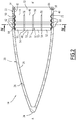
Figure 2 est une vue en coupe axiale d'une coiffe de fusée de la fusée de laFigure 1 , selon un premier mode de réalisation de l'invention, - la
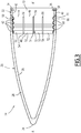
Figure 3 est une vue en coupe axiale de la coiffe de fusée de la fusée de laFigure 1 , selon un deuxième mode de réalisation de l'invention, et - la
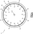
Figure 4 est une en coupe radiale de la coiffe de fusée de laFigure 2 , selon un plan marqué IV-IV sur laFigure 2 . - La fusée 10 représenté sur la
Figure 1 comprend un corps 12 sensiblement cylindrique allongé suivant un axe longitudinal A-A', et une coiffe 14 disposée à une extrémité axiale avant du corps 12. - La fusée 10 est une fusée autoguidée adaptée pour atteindre une cible de manière autonome, sans intervention extérieure. A cet effet, la fusée 10 comprend un autodirecteur 16 logé dans la coiffe 14.
- En référence à la
Figure 2 , la coiffe 14 comprend une coque ogivale 20 et une virole 22 pour la fixation de la coque ogivale 20 au corps 12. - La coque ogivale 20 est sensiblement coaxiale à l'axe A-A'. Elle définit une extrémité avant 24 de la fusée 10 formée par la pointe de l'ogive.
- Cette extrémité avant 24 constitue également l'extrémité avant de la coiffe 14.
- La coque ogivale 20 présente une face intérieure 26 et une face extérieure 28.
- La coque ogivale 20 est de préférence formée d'une pièce.
- La coque ogivale 20 est réalisée en un premier matériau et est en particulier constituée de ce premier matériau.
- Le premier matériau est transparent aux ondes électromagnétiques. Ainsi, l'autodirecteur 16 peut scanner l'environnement extérieur de la fusée 10 à travers la coque 20.
- Le premier matériau est également résistant aux fortes contraintes thermiques, par exemple aux températures supérieures à 700°C.
- A cet effet, le premier matériau est constitué par une céramique. De préférence, cette céramique est de la silice ; ainsi, la transparence de la coque 20 aux ondes électromagnétiques est renforcée.
- Le premier matériau a un coefficient d'expansion thermique inférieur à 10-6 K-1 sur une large plage de température au-delà de 700°C.
- La virole 22 est formée d'une pièce.
- La virole 22 est de préférence réalisée par fabrication additive, en particulier par fusion sélective par laser.
- La virole 22 est réalisée en un deuxième matériau et est en particulier constituée de ce deuxième matériau.
- Le deuxième matériau a un coefficient d'expansion thermique à 300°C supérieur au coefficient d'expansion thermique du premier matériau à la même température. En d'autres termes, le premier matériau a un coefficient d'expansion thermique à 300°C inférieur au coefficient d'expansion thermique du deuxième matériau à la même température.
- Par exemple, le deuxième matériau a un coefficient d'expansion thermique compris entre 8.10-6 et 10-5 K-1 sur une large plage de température au-delà de 300°C..
- Le deuxième matériau est de préférence constitué par du titane, par exemple du titane TA6V. Ainsi, la virole 22 présente d'excellentes propriétés mécaniques, même pour des températures élevées, est légère, et est résistante à la corrosion.
- La virole 22 comprend un socle annulaire 30 et un manchon d'accouplement 32.
- Le socle annulaire 30 est sensiblement coaxial à l'axe A-A'.
- Le socle annulaire 30 définit une extrémité arrière 34 de la coiffe 14.
- Le socle annulaire 30 présente des organes 36 de fixation au corps 12. Ces organes de fixation 36 sont ici formés par des orifices radiaux aptes au passage de vis 38 destinées à être visées au corps 12. En variante (non représentée), les organes de fixation 36 sont formés par un taraudage du socle 30 adapté pour le vissage du socle 30 sur le corps 12.
- Le socle annulaire 30 présente une face périphérique externe 40 et une face périphérique interne 42. La face périphérique externe 40 s'inscrit ici dans le prolongement de la face externe 28 de la coque 20.
- Le socle annulaire 30 est disposé axialement à l'écart de la coque 20.
- Le socle annulaire 30 présente également une extrémité avant 44. Cette extrémité avant 44 est à l'opposé de l'extrémité arrière 34.
- L'extrémité avant 44 est chanfreinée. Le chanfrein est ici formé dans la face périphérique externe 40 du socle 30.
- Le manchon 32 est sensiblement centré sur l'axe A-A'
- Le manchon 32 fait saillie axialement vers l'avant depuis le socle annulaire 30, en particulier depuis l'extrémité avant 44 du socle annulaire 30.
- Le manchon 32 s'étend axialement depuis une extrémité proximale 46 de raccordement au socle 30 jusqu'à une extrémité distale 48 opposée au socle 30.
- Le manchon 32 est emmanché avec la coque 20 et est collé à la coque 20. Dans l'exemple représenté, il est emmanché dans la coque 20 et est collé à la face interne 26 de la coque 20. En variante (non représentée), le manchon 32 est emmanché sur la coque 20 et est collé à la face externe 28 de la coque 20.
- Comme on l'a vu plus haut, le manchon 32 est réalisé dans un matériau présentant un coefficient d'expansion thermique supérieur à celui de la coque 20. Lorsque la coiffe 14 sera soumise à des échauffements aérodynamiques, le manchon 32 va donc se dilater davantage que la coque 20. Afin d'éviter que ces dilatation n'entraînent la rupture de la coque 20, le manchon 32 présente un assouplissement radial apte à absorber la dilatation thermique radiale du manchon 32, et un assouplissement axial apte à absorber la dilatation thermique axiale du manchon 32.
- En outre, le manchon 32 est collé à la coque 20 par l'intermédiaire d'une colle souple telle qu'une colle silicone ou une colle polyuréthane.
- Cette colle forme une couche de colle 50 à l'interface entre le manchon 32 et la coque 20.
- L'assouplissement radial est formé par le découpage du manchon 32 en une pluralité de lamelles 52 réparties autour de l'axe A-A'.
- Chaque lamelle 52 s'étend de manière sensiblement rectiligne depuis l'extrémité proximale 46 jusqu'à l'extrémité distale 48 du manchon 32.
- Chaque lamelle 52 est espacée orthoradialement de ses lamelles 52 voisines.
- En d'autres termes, le manchon 32 présente une pluralité de fentes axiales 54 traversant chacune radialement le manchon 32 et s'étendant axialement depuis l'extrémité proximale 46 jusqu'à l'extrémité distale 48. Chaque fente axiale 54 sépare l'une de l'autre deux lamelles 52 voisines.
- Chaque lamelle 52 est collée aux lamelles 52 voisines par l'intermédiaire d'un cordon de colle souple 56. Ce cordon de colle 56 comble la fente 54 ménagée entre les lamelles 52.
- Cette colle souple est typiquement constituée par une colle silicone ou une colle polyuréthane.
- L'assouplissement axial est formé par une ondulation du manchon 32 parallèlement à l'axe A-A', c'est-à-dire par une déformation du manchon 32 telle que celui-ci présente une succession de creux 60 et de bosses 62 succédant les unes aux autres suivant une direction parallèle à l'axe A-A'.
- Les creux 60 sont formés par des parties du manchon 32 qui sont éloignées de l'axe A-A' par rapport à une distance moyenne du manchon 32 à l'axe A-A'. Les bosses 62 sont formés par des parties du manchon 32 qui sont rapprochées de l'axe A-A' par rapport à une distance moyenne du manchon 32 à l'axe A-A'.
- Chaque creux 60 est circonférentiel, c'est-à-dire qu'il se prolonge sur tout le manchon 32 tout autour de l'axe A-A'. En particulier, chaque creux 60 se prolonge d'une lamelle 52 à l'autre.
- De même, chaque bosse 62 est circonférentielle.
- Le manchon 32 présente ainsi une forme de tube ondulé.
- Dans l'exemple de la
Figure 2 , la coque 20 présente un taraudage 64 complémentaire à cette ondulation. Cela permet de renforcer la tenue de la coque 20 sur le manchon 32. - Dans la variante non représentée où le manchon 32 est emmanché sur la coque 20, la coque 20 présente de préférence un filetage complémentaire à l'ondulation, pour l'obtention du même résultat.
- Dans l'exemple de la
Figure 3 , la coque 20 ne présente ni taraudage ni filetage. A la place, le tronçon d'extrémité arrière 66 de la coque 20, disposée radialement au droit du manchon 32, est simplement aminci. - Ici, la coiffe 14 comprend également une cale 70 interposée entre la coque 20 et l'extrémité avant 44 du socle 30 de la virole 22.
- Cette cale 70 est en appui contre la face arrière de la coque 20 et la face externe 40 du socle 30. Elle permet d'éviter un contact direct du métal du socle 30 avec la silice de la coque 20, un tel contact direct pouvant être dommageable à la silice.
- La cale 70 est typiquement réalisée en matière plastique apte à supporter des températures élevées, en Viton® par exemple, et est de préférence constituée de ce matériau.
- Ainsi, la coiffe de fusée 14 est adaptée pour des utilisations où la virole 22 est soumise à des températures élevées puisque, même si le matériau formant la virole 22 présente un coefficient d'expansion thermique supérieur à celui du matériau de la coque ogivale 20, il peut se dilater sans risque de rupture de la coque ogivale 20. Ceci est renforcé par l'emploi de titane, qui permet de garantir pour la virole 22 une excellente résistance, même à température élevée.
- En outre, le poids et le coût de la coiffe 14 sont réduits.
- Enfin, la production de la coiffe 14 est accélérée, puisque celle-ci emploie des produits couramment disponibles dans le commerce ne nécessitant en outre aucun traitement particulier.
Claims (15)
- Coiffe de fusée (14) comprenant une coque ogivale (20) en un premier matériau et une virole (22) en un deuxième matériau pour la fixation de la coque ogivale (20) à un corps de fusée (12), la virole (22) comprenant un manchon (32) centré sur un axe (A-A'), emmanché avec la coque ogivale (20) et collé à la coque ogivale (20), caractérisée en ce que ledit manchon (32) présente un assouplissement radial apte à absorber la dilatation thermique radiale du manchon (32), et/ou un assouplissement axial apte à absorber la dilatation thermique axiale du manchon (32).
- Coiffe de fusée (14) selon la revendication 1, dans laquelle la virole (22) comprend un socle annulaire (30) sensiblement coaxial au manchon (32), le manchon (32) faisant saillie depuis ledit socle annulaire (30).
- Coiffe de fusée (14) selon la revendication 1 ou 2, dans laquelle l'assouplissement radial est formé par le découpage du manchon (32) en une pluralité de lamelles (52) réparties autour de l'axe (A-A').
- Coiffe de fusée (14) selon les revendications 2 et 3 prises ensemble, dans laquelle le manchon (32) s'étend axialement depuis une extrémité proximale (46) de raccordement au socle annulaire (30) jusqu'à une extrémité distale (48) opposée, chaque lamelle (52) s'étendant depuis l'extrémité proximale (46) jusqu'à l'extrémité distale (48).
- Coiffe de fusée (14) selon la revendication 3 ou 4, dans laquelle chaque lamelle (52) est collée aux lamelles (52) voisines par l'intermédiaire d'un cordon de colle souple (56) telle qu'une colle silicone ou une colle polyuréthane.
- Coiffe de fusée (14) selon l'une quelconque des revendications précédentes, dans laquelle l'assouplissement axial est formé par une ondulation du manchon (32) parallèlement à l'axe (A-A').
- Coiffe de fusée (14) selon la revendication 6, dans laquelle la coque ogivale (20) présente un taraudage ou un filetage complémentaire à l'ondulation du manchon (32).
- Coiffe de fusée (14) selon l'une quelconque des revendications précédentes, dans laquelle le premier matériau a un coefficient d'expansion thermique à 300°C inférieur au coefficient d'expansion thermique du deuxième matériau à la même température.
- Coiffe de fusée (14) selon l'une quelconque des revendications précédentes, dans laquelle le premier matériau est transparent aux ondes électromagnétiques.
- Coiffe de fusée (14) selon l'une quelconque des revendications précédentes, dans laquelle le premier matériau est constitué par une céramique, par exemple par de la silice.
- Coiffe de fusée (14) selon l'une quelconque des revendications précédentes, dans laquelle le deuxième matériau est constitué par du titane, par exemple du titane TA6V.
- Coiffe de fusée (14) selon l'une quelconque des revendications précédentes, dans laquelle le manchon (32) est collé à la coque ogivale (20) par l'intermédiaire d'une colle souple telle qu'une colle silicone ou une colle polyuréthane.
- Coiffe de fusée (14) selon l'une quelconque des revendications précédentes, dans laquelle la virole (22) est formée d'une pièce.
- Coiffe de fusée (14) selon l'une quelconque des revendications précédentes, dans laquelle la virole (22) est réalisée par fabrication additive, en particulier par fusion sélective par laser.
- Fusée (10) comprenant une coiffe de fusée (14) selon l'une quelconque des revendications précédentes.
Applications Claiming Priority (1)
| Application Number | Priority Date | Filing Date | Title |
|---|---|---|---|
| FR1871517A FR3088421B1 (fr) | 2018-11-13 | 2018-11-13 | Coiffe de fusee avec manchon presentant un assouplissement radial et/ou un assouplissement axial |
Publications (2)
| Publication Number | Publication Date |
|---|---|
| EP3653986A1 true EP3653986A1 (fr) | 2020-05-20 |
| EP3653986B1 EP3653986B1 (fr) | 2022-06-29 |
Family
ID=66530110
Family Applications (1)
| Application Number | Title | Priority Date | Filing Date |
|---|---|---|---|
| EP19207904.4A Active EP3653986B1 (fr) | 2018-11-13 | 2019-11-08 | Coiffe de fusée avec manchon présentant un assouplissement radial et/ou un assouplissement axial |
Country Status (3)
| Country | Link |
|---|---|
| EP (1) | EP3653986B1 (fr) |
| ES (1) | ES2924700T3 (fr) |
| FR (1) | FR3088421B1 (fr) |
Citations (4)
| Publication number | Priority date | Publication date | Assignee | Title |
|---|---|---|---|---|
| FR2279968A1 (fr) | 1974-07-23 | 1976-02-20 | Dassault Electronique | Procede de fixation d'un radome sur une virole metallique et moyen de fixation correspondant |
| US4520364A (en) * | 1983-04-19 | 1985-05-28 | The United States Of America As Represented By The Secretary Of The Air Force | Attachment method-ceramic radome to metal body |
| RU2624793C1 (ru) * | 2016-09-19 | 2017-07-06 | Акционерное общество "Обнинское научно-производственное предприятие "Технология" им. А.Г. Ромашина" | Антенный обтекатель |
| JP2018132214A (ja) * | 2017-02-13 | 2018-08-23 | 三菱電機株式会社 | 飛しょう体用レドーム |
-
2018
- 2018-11-13 FR FR1871517A patent/FR3088421B1/fr not_active Expired - Fee Related
-
2019
- 2019-11-08 ES ES19207904T patent/ES2924700T3/es active Active
- 2019-11-08 EP EP19207904.4A patent/EP3653986B1/fr active Active
Patent Citations (4)
| Publication number | Priority date | Publication date | Assignee | Title |
|---|---|---|---|---|
| FR2279968A1 (fr) | 1974-07-23 | 1976-02-20 | Dassault Electronique | Procede de fixation d'un radome sur une virole metallique et moyen de fixation correspondant |
| US4520364A (en) * | 1983-04-19 | 1985-05-28 | The United States Of America As Represented By The Secretary Of The Air Force | Attachment method-ceramic radome to metal body |
| RU2624793C1 (ru) * | 2016-09-19 | 2017-07-06 | Акционерное общество "Обнинское научно-производственное предприятие "Технология" им. А.Г. Ромашина" | Антенный обтекатель |
| JP2018132214A (ja) * | 2017-02-13 | 2018-08-23 | 三菱電機株式会社 | 飛しょう体用レドーム |
Also Published As
| Publication number | Publication date |
|---|---|
| ES2924700T3 (es) | 2022-10-10 |
| FR3088421B1 (fr) | 2022-04-01 |
| EP3653986B1 (fr) | 2022-06-29 |
| FR3088421A1 (fr) | 2020-05-15 |
Similar Documents
| Publication | Publication Date | Title |
|---|---|---|
| EP3596313B1 (fr) | Ensemble d'anneau de turbine | |
| EP3596315B1 (fr) | Ensemble d'anneau de turbine | |
| EP3596314B1 (fr) | Ensemble d'anneau de turbine | |
| EP3325819B1 (fr) | Assemblage par liaison mécanique comportant au moins une pièce en matériau composite | |
| EP0636825B1 (fr) | Système de raccordement d'un tuyau véhiculant un fluide chaud à un organe en matière plastique et son utilisation dans un moteur à combustion interne | |
| EP3857030B1 (fr) | Ensemble pour une turbine de turbomachine et turbomachine associée | |
| EP0918208A1 (fr) | Balle expansive | |
| CH692093A5 (fr) | Joint d'étanchéité annulaire. | |
| FR2965598A1 (fr) | Assemblage de soufflet d'etancheite soude | |
| FR2735187A1 (fr) | Poussoir a actionnement unique motorise par un materiau a memoire de forme. | |
| EP0626555B1 (fr) | Projectile d'exercice et procédé de fabrication | |
| EP3673311B1 (fr) | Telescope a montage simplifie | |
| EP3653986B1 (fr) | Coiffe de fusée avec manchon présentant un assouplissement radial et/ou un assouplissement axial | |
| EP0687884B1 (fr) | Manchon anti-arcure | |
| EP3803127B1 (fr) | Architecture thermique de compresseur d'air | |
| FR2883995A1 (fr) | Element thermostatique, notamment pour thermostat de circuit de refroidissement, et procede de fabrication d'un tel element | |
| EP4259943B1 (fr) | Dispositif de fixation mecanique a l'extremite d'un tube | |
| FR3019864A1 (fr) | Assemblage rivete et procede de fabrication associe | |
| EP1068437B1 (fr) | Systeme d'activation de tuyere orientable pour propulseur a reaction utilisant plusieurs ensembles elastiques repartis circonferentiellement | |
| EP0482977A1 (fr) | Corps de joint de transmission du type comportant une bride de liaison | |
| EP3847363B1 (fr) | Turbomachine a double flux | |
| FR2877994A1 (fr) | Support de palier, et moteur d'aeronef equipe d'un tel support de palier. | |
| FR3057333A1 (fr) | Ensemble de bridage avec joint d'etancheite | |
| FR2594202A1 (fr) | Robinet a tournant spherique | |
| EP1416127B1 (fr) | Système et ensemble de soupape de moteur à combustion interne comportant un écran solidaire du guide |
Legal Events
| Date | Code | Title | Description |
|---|---|---|---|
| PUAI | Public reference made under article 153(3) epc to a published international application that has entered the european phase |
Free format text: ORIGINAL CODE: 0009012 |
|
| STAA | Information on the status of an ep patent application or granted ep patent |
Free format text: STATUS: THE APPLICATION HAS BEEN PUBLISHED |
|
| AK | Designated contracting states |
Kind code of ref document: A1 Designated state(s): AL AT BE BG CH CY CZ DE DK EE ES FI FR GB GR HR HU IE IS IT LI LT LU LV MC MK MT NL NO PL PT RO RS SE SI SK SM TR |
|
| AX | Request for extension of the european patent |
Extension state: BA ME |
|
| STAA | Information on the status of an ep patent application or granted ep patent |
Free format text: STATUS: REQUEST FOR EXAMINATION WAS MADE |
|
| 17P | Request for examination filed |
Effective date: 20201022 |
|
| RBV | Designated contracting states (corrected) |
Designated state(s): AL AT BE BG CH CY CZ DE DK EE ES FI FR GB GR HR HU IE IS IT LI LT LU LV MC MK MT NL NO PL PT RO RS SE SI SK SM TR |
|
| RIN1 | Information on inventor provided before grant (corrected) |
Inventor name: BOURLOTON, REGIS |
|
| RIC1 | Information provided on ipc code assigned before grant |
Ipc: F42B 15/34 20060101ALN20211208BHEP Ipc: F42B 10/46 20060101AFI20211208BHEP |
|
| RIC1 | Information provided on ipc code assigned before grant |
Ipc: F42B 15/34 20060101ALN20211220BHEP Ipc: F42B 10/46 20060101AFI20211220BHEP |
|
| GRAP | Despatch of communication of intention to grant a patent |
Free format text: ORIGINAL CODE: EPIDOSNIGR1 |
|
| STAA | Information on the status of an ep patent application or granted ep patent |
Free format text: STATUS: GRANT OF PATENT IS INTENDED |
|
| INTG | Intention to grant announced |
Effective date: 20220201 |
|
| GRAS | Grant fee paid |
Free format text: ORIGINAL CODE: EPIDOSNIGR3 |
|
| GRAA | (expected) grant |
Free format text: ORIGINAL CODE: 0009210 |
|
| STAA | Information on the status of an ep patent application or granted ep patent |
Free format text: STATUS: THE PATENT HAS BEEN GRANTED |
|
| AK | Designated contracting states |
Kind code of ref document: B1 Designated state(s): AL AT BE BG CH CY CZ DE DK EE ES FI FR GB GR HR HU IE IS IT LI LT LU LV MC MK MT NL NO PL PT RO RS SE SI SK SM TR |
|
| REG | Reference to a national code |
Ref country code: CH Ref legal event code: EP |
|
| REG | Reference to a national code |
Ref country code: AT Ref legal event code: REF Ref document number: 1501616 Country of ref document: AT Kind code of ref document: T Effective date: 20220715 |
|
| REG | Reference to a national code |
Ref country code: IE Ref legal event code: FG4D Free format text: LANGUAGE OF EP DOCUMENT: FRENCH |
|
| REG | Reference to a national code |
Ref country code: DE Ref legal event code: R096 Ref document number: 602019016390 Country of ref document: DE |
|
| REG | Reference to a national code |
Ref country code: SE Ref legal event code: TRGR |
|
| REG | Reference to a national code |
Ref country code: LT Ref legal event code: MG9D Ref country code: ES Ref legal event code: FG2A Ref document number: 2924700 Country of ref document: ES Kind code of ref document: T3 Effective date: 20221010 |
|
| PG25 | Lapsed in a contracting state [announced via postgrant information from national office to epo] |
Ref country code: NO Free format text: LAPSE BECAUSE OF FAILURE TO SUBMIT A TRANSLATION OF THE DESCRIPTION OR TO PAY THE FEE WITHIN THE PRESCRIBED TIME-LIMIT Effective date: 20220929 Ref country code: LT Free format text: LAPSE BECAUSE OF FAILURE TO SUBMIT A TRANSLATION OF THE DESCRIPTION OR TO PAY THE FEE WITHIN THE PRESCRIBED TIME-LIMIT Effective date: 20220629 Ref country code: HR Free format text: LAPSE BECAUSE OF FAILURE TO SUBMIT A TRANSLATION OF THE DESCRIPTION OR TO PAY THE FEE WITHIN THE PRESCRIBED TIME-LIMIT Effective date: 20220629 Ref country code: GR Free format text: LAPSE BECAUSE OF FAILURE TO SUBMIT A TRANSLATION OF THE DESCRIPTION OR TO PAY THE FEE WITHIN THE PRESCRIBED TIME-LIMIT Effective date: 20220930 Ref country code: FI Free format text: LAPSE BECAUSE OF FAILURE TO SUBMIT A TRANSLATION OF THE DESCRIPTION OR TO PAY THE FEE WITHIN THE PRESCRIBED TIME-LIMIT Effective date: 20220629 Ref country code: BG Free format text: LAPSE BECAUSE OF FAILURE TO SUBMIT A TRANSLATION OF THE DESCRIPTION OR TO PAY THE FEE WITHIN THE PRESCRIBED TIME-LIMIT Effective date: 20220929 |
|
| REG | Reference to a national code |
Ref country code: NL Ref legal event code: MP Effective date: 20220629 |
|
| REG | Reference to a national code |
Ref country code: AT Ref legal event code: MK05 Ref document number: 1501616 Country of ref document: AT Kind code of ref document: T Effective date: 20220629 |
|
| PG25 | Lapsed in a contracting state [announced via postgrant information from national office to epo] |
Ref country code: RS Free format text: LAPSE BECAUSE OF FAILURE TO SUBMIT A TRANSLATION OF THE DESCRIPTION OR TO PAY THE FEE WITHIN THE PRESCRIBED TIME-LIMIT Effective date: 20220629 Ref country code: LV Free format text: LAPSE BECAUSE OF FAILURE TO SUBMIT A TRANSLATION OF THE DESCRIPTION OR TO PAY THE FEE WITHIN THE PRESCRIBED TIME-LIMIT Effective date: 20220629 |
|
| PG25 | Lapsed in a contracting state [announced via postgrant information from national office to epo] |
Ref country code: NL Free format text: LAPSE BECAUSE OF FAILURE TO SUBMIT A TRANSLATION OF THE DESCRIPTION OR TO PAY THE FEE WITHIN THE PRESCRIBED TIME-LIMIT Effective date: 20220629 |
|
| PG25 | Lapsed in a contracting state [announced via postgrant information from national office to epo] |
Ref country code: SM Free format text: LAPSE BECAUSE OF FAILURE TO SUBMIT A TRANSLATION OF THE DESCRIPTION OR TO PAY THE FEE WITHIN THE PRESCRIBED TIME-LIMIT Effective date: 20220629 Ref country code: SK Free format text: LAPSE BECAUSE OF FAILURE TO SUBMIT A TRANSLATION OF THE DESCRIPTION OR TO PAY THE FEE WITHIN THE PRESCRIBED TIME-LIMIT Effective date: 20220629 Ref country code: RO Free format text: LAPSE BECAUSE OF FAILURE TO SUBMIT A TRANSLATION OF THE DESCRIPTION OR TO PAY THE FEE WITHIN THE PRESCRIBED TIME-LIMIT Effective date: 20220629 Ref country code: PT Free format text: LAPSE BECAUSE OF FAILURE TO SUBMIT A TRANSLATION OF THE DESCRIPTION OR TO PAY THE FEE WITHIN THE PRESCRIBED TIME-LIMIT Effective date: 20221031 Ref country code: EE Free format text: LAPSE BECAUSE OF FAILURE TO SUBMIT A TRANSLATION OF THE DESCRIPTION OR TO PAY THE FEE WITHIN THE PRESCRIBED TIME-LIMIT Effective date: 20220629 Ref country code: AT Free format text: LAPSE BECAUSE OF FAILURE TO SUBMIT A TRANSLATION OF THE DESCRIPTION OR TO PAY THE FEE WITHIN THE PRESCRIBED TIME-LIMIT Effective date: 20220629 |
|
| PG25 | Lapsed in a contracting state [announced via postgrant information from national office to epo] |
Ref country code: PL Free format text: LAPSE BECAUSE OF FAILURE TO SUBMIT A TRANSLATION OF THE DESCRIPTION OR TO PAY THE FEE WITHIN THE PRESCRIBED TIME-LIMIT Effective date: 20220629 Ref country code: IS Free format text: LAPSE BECAUSE OF FAILURE TO SUBMIT A TRANSLATION OF THE DESCRIPTION OR TO PAY THE FEE WITHIN THE PRESCRIBED TIME-LIMIT Effective date: 20221029 |
|
| REG | Reference to a national code |
Ref country code: DE Ref legal event code: R097 Ref document number: 602019016390 Country of ref document: DE |
|
| PG25 | Lapsed in a contracting state [announced via postgrant information from national office to epo] |
Ref country code: AL Free format text: LAPSE BECAUSE OF FAILURE TO SUBMIT A TRANSLATION OF THE DESCRIPTION OR TO PAY THE FEE WITHIN THE PRESCRIBED TIME-LIMIT Effective date: 20220629 |
|
| PG25 | Lapsed in a contracting state [announced via postgrant information from national office to epo] |
Ref country code: DK Free format text: LAPSE BECAUSE OF FAILURE TO SUBMIT A TRANSLATION OF THE DESCRIPTION OR TO PAY THE FEE WITHIN THE PRESCRIBED TIME-LIMIT Effective date: 20220629 Ref country code: CZ Free format text: LAPSE BECAUSE OF FAILURE TO SUBMIT A TRANSLATION OF THE DESCRIPTION OR TO PAY THE FEE WITHIN THE PRESCRIBED TIME-LIMIT Effective date: 20220629 |
|
| PLBE | No opposition filed within time limit |
Free format text: ORIGINAL CODE: 0009261 |
|
| STAA | Information on the status of an ep patent application or granted ep patent |
Free format text: STATUS: NO OPPOSITION FILED WITHIN TIME LIMIT |
|
| 26N | No opposition filed |
Effective date: 20230330 |
|
| P01 | Opt-out of the competence of the unified patent court (upc) registered |
Effective date: 20230522 |
|
| PG25 | Lapsed in a contracting state [announced via postgrant information from national office to epo] |
Ref country code: MC Free format text: LAPSE BECAUSE OF FAILURE TO SUBMIT A TRANSLATION OF THE DESCRIPTION OR TO PAY THE FEE WITHIN THE PRESCRIBED TIME-LIMIT Effective date: 20220629 |
|
| REG | Reference to a national code |
Ref country code: CH Ref legal event code: PL |
|
| REG | Reference to a national code |
Ref country code: BE Ref legal event code: MM Effective date: 20221130 |
|
| PG25 | Lapsed in a contracting state [announced via postgrant information from national office to epo] |
Ref country code: LI Free format text: LAPSE BECAUSE OF NON-PAYMENT OF DUE FEES Effective date: 20221130 Ref country code: CH Free format text: LAPSE BECAUSE OF NON-PAYMENT OF DUE FEES Effective date: 20221130 |
|
| PG25 | Lapsed in a contracting state [announced via postgrant information from national office to epo] |
Ref country code: SI Free format text: LAPSE BECAUSE OF FAILURE TO SUBMIT A TRANSLATION OF THE DESCRIPTION OR TO PAY THE FEE WITHIN THE PRESCRIBED TIME-LIMIT Effective date: 20220629 Ref country code: LU Free format text: LAPSE BECAUSE OF NON-PAYMENT OF DUE FEES Effective date: 20221108 |
|
| PG25 | Lapsed in a contracting state [announced via postgrant information from national office to epo] |
Ref country code: IE Free format text: LAPSE BECAUSE OF NON-PAYMENT OF DUE FEES Effective date: 20221108 |
|
| PG25 | Lapsed in a contracting state [announced via postgrant information from national office to epo] |
Ref country code: BE Free format text: LAPSE BECAUSE OF NON-PAYMENT OF DUE FEES Effective date: 20221130 |
|
| PG25 | Lapsed in a contracting state [announced via postgrant information from national office to epo] |
Ref country code: HU Free format text: LAPSE BECAUSE OF FAILURE TO SUBMIT A TRANSLATION OF THE DESCRIPTION OR TO PAY THE FEE WITHIN THE PRESCRIBED TIME-LIMIT; INVALID AB INITIO Effective date: 20191108 |
|
| PG25 | Lapsed in a contracting state [announced via postgrant information from national office to epo] |
Ref country code: CY Free format text: LAPSE BECAUSE OF FAILURE TO SUBMIT A TRANSLATION OF THE DESCRIPTION OR TO PAY THE FEE WITHIN THE PRESCRIBED TIME-LIMIT Effective date: 20220629 |
|
| PG25 | Lapsed in a contracting state [announced via postgrant information from national office to epo] |
Ref country code: MK Free format text: LAPSE BECAUSE OF FAILURE TO SUBMIT A TRANSLATION OF THE DESCRIPTION OR TO PAY THE FEE WITHIN THE PRESCRIBED TIME-LIMIT Effective date: 20220629 |
|
| PG25 | Lapsed in a contracting state [announced via postgrant information from national office to epo] |
Ref country code: MT Free format text: LAPSE BECAUSE OF FAILURE TO SUBMIT A TRANSLATION OF THE DESCRIPTION OR TO PAY THE FEE WITHIN THE PRESCRIBED TIME-LIMIT Effective date: 20220629 |
|
| PG25 | Lapsed in a contracting state [announced via postgrant information from national office to epo] |
Ref country code: BG Free format text: LAPSE BECAUSE OF FAILURE TO SUBMIT A TRANSLATION OF THE DESCRIPTION OR TO PAY THE FEE WITHIN THE PRESCRIBED TIME-LIMIT Effective date: 20220629 |
|
| PG25 | Lapsed in a contracting state [announced via postgrant information from national office to epo] |
Ref country code: BG Free format text: LAPSE BECAUSE OF FAILURE TO SUBMIT A TRANSLATION OF THE DESCRIPTION OR TO PAY THE FEE WITHIN THE PRESCRIBED TIME-LIMIT Effective date: 20220629 |
|
| PG25 | Lapsed in a contracting state [announced via postgrant information from national office to epo] |
Ref country code: TR Free format text: LAPSE BECAUSE OF FAILURE TO SUBMIT A TRANSLATION OF THE DESCRIPTION OR TO PAY THE FEE WITHIN THE PRESCRIBED TIME-LIMIT Effective date: 20220629 |
|
| PGFP | Annual fee paid to national office [announced via postgrant information from national office to epo] |
Ref country code: DE Payment date: 20251117 Year of fee payment: 7 |
|
| PGFP | Annual fee paid to national office [announced via postgrant information from national office to epo] |
Ref country code: GB Payment date: 20251126 Year of fee payment: 7 |
|
| PGFP | Annual fee paid to national office [announced via postgrant information from national office to epo] |
Ref country code: IT Payment date: 20251110 Year of fee payment: 7 |
|
| PGFP | Annual fee paid to national office [announced via postgrant information from national office to epo] |
Ref country code: FR Payment date: 20251127 Year of fee payment: 7 |
|
| PGFP | Annual fee paid to national office [announced via postgrant information from national office to epo] |
Ref country code: SE Payment date: 20251121 Year of fee payment: 7 |
|
| PGFP | Annual fee paid to national office [announced via postgrant information from national office to epo] |
Ref country code: ES Payment date: 20251210 Year of fee payment: 7 |