EP3653944A1 - Indoor unit for air conditioner comprising refrigerant detection sensor - Google Patents
Indoor unit for air conditioner comprising refrigerant detection sensor Download PDFInfo
- Publication number
- EP3653944A1 EP3653944A1 EP18831682.2A EP18831682A EP3653944A1 EP 3653944 A1 EP3653944 A1 EP 3653944A1 EP 18831682 A EP18831682 A EP 18831682A EP 3653944 A1 EP3653944 A1 EP 3653944A1
- Authority
- EP
- European Patent Office
- Prior art keywords
- air
- blow
- indoor unit
- detection sensor
- flow
- Prior art date
- Legal status (The legal status is an assumption and is not a legal conclusion. Google has not performed a legal analysis and makes no representation as to the accuracy of the status listed.)
- Pending
Links
- 239000003507 refrigerant Substances 0.000 title claims abstract description 179
- 238000001514 detection method Methods 0.000 title claims abstract description 130
- 230000000694 effects Effects 0.000 description 9
- 238000004378 air conditioning Methods 0.000 description 7
- 230000005484 gravity Effects 0.000 description 3
- 239000007788 liquid Substances 0.000 description 2
- 238000009434 installation Methods 0.000 description 1
Images



Classifications
-
- F—MECHANICAL ENGINEERING; LIGHTING; HEATING; WEAPONS; BLASTING
- F24—HEATING; RANGES; VENTILATING
- F24F—AIR-CONDITIONING; AIR-HUMIDIFICATION; VENTILATION; USE OF AIR CURRENTS FOR SCREENING
- F24F11/00—Control or safety arrangements
- F24F11/30—Control or safety arrangements for purposes related to the operation of the system, e.g. for safety or monitoring
- F24F11/32—Responding to malfunctions or emergencies
- F24F11/36—Responding to malfunctions or emergencies to leakage of heat-exchange fluid
-
- F—MECHANICAL ENGINEERING; LIGHTING; HEATING; WEAPONS; BLASTING
- F24—HEATING; RANGES; VENTILATING
- F24F—AIR-CONDITIONING; AIR-HUMIDIFICATION; VENTILATION; USE OF AIR CURRENTS FOR SCREENING
- F24F1/00—Room units for air-conditioning, e.g. separate or self-contained units or units receiving primary air from a central station
- F24F1/0007—Indoor units, e.g. fan coil units
- F24F1/0011—Indoor units, e.g. fan coil units characterised by air outlets
-
- F—MECHANICAL ENGINEERING; LIGHTING; HEATING; WEAPONS; BLASTING
- F24—HEATING; RANGES; VENTILATING
- F24F—AIR-CONDITIONING; AIR-HUMIDIFICATION; VENTILATION; USE OF AIR CURRENTS FOR SCREENING
- F24F1/00—Room units for air-conditioning, e.g. separate or self-contained units or units receiving primary air from a central station
- F24F1/0007—Indoor units, e.g. fan coil units
- F24F1/0068—Indoor units, e.g. fan coil units characterised by the arrangement of refrigerant piping outside the heat exchanger within the unit casing
-
- F—MECHANICAL ENGINEERING; LIGHTING; HEATING; WEAPONS; BLASTING
- F24—HEATING; RANGES; VENTILATING
- F24F—AIR-CONDITIONING; AIR-HUMIDIFICATION; VENTILATION; USE OF AIR CURRENTS FOR SCREENING
- F24F1/00—Room units for air-conditioning, e.g. separate or self-contained units or units receiving primary air from a central station
- F24F1/0007—Indoor units, e.g. fan coil units
- F24F1/0071—Indoor units, e.g. fan coil units with means for purifying supplied air
- F24F1/0073—Indoor units, e.g. fan coil units with means for purifying supplied air characterised by the mounting or arrangement of filters
-
- F—MECHANICAL ENGINEERING; LIGHTING; HEATING; WEAPONS; BLASTING
- F24—HEATING; RANGES; VENTILATING
- F24F—AIR-CONDITIONING; AIR-HUMIDIFICATION; VENTILATION; USE OF AIR CURRENTS FOR SCREENING
- F24F13/00—Details common to, or for air-conditioning, air-humidification, ventilation or use of air currents for screening
- F24F13/02—Ducting arrangements
- F24F13/06—Outlets for directing or distributing air into rooms or spaces, e.g. ceiling air diffuser
- F24F13/068—Outlets for directing or distributing air into rooms or spaces, e.g. ceiling air diffuser formed as perforated walls, ceilings or floors
-
- F—MECHANICAL ENGINEERING; LIGHTING; HEATING; WEAPONS; BLASTING
- F24—HEATING; RANGES; VENTILATING
- F24F—AIR-CONDITIONING; AIR-HUMIDIFICATION; VENTILATION; USE OF AIR CURRENTS FOR SCREENING
- F24F13/00—Details common to, or for air-conditioning, air-humidification, ventilation or use of air currents for screening
- F24F13/08—Air-flow control members, e.g. louvres, grilles, flaps or guide plates
- F24F13/10—Air-flow control members, e.g. louvres, grilles, flaps or guide plates movable, e.g. dampers
-
- F—MECHANICAL ENGINEERING; LIGHTING; HEATING; WEAPONS; BLASTING
- F24—HEATING; RANGES; VENTILATING
- F24F—AIR-CONDITIONING; AIR-HUMIDIFICATION; VENTILATION; USE OF AIR CURRENTS FOR SCREENING
- F24F13/00—Details common to, or for air-conditioning, air-humidification, ventilation or use of air currents for screening
- F24F13/20—Casings or covers
-
- F—MECHANICAL ENGINEERING; LIGHTING; HEATING; WEAPONS; BLASTING
- F24—HEATING; RANGES; VENTILATING
- F24F—AIR-CONDITIONING; AIR-HUMIDIFICATION; VENTILATION; USE OF AIR CURRENTS FOR SCREENING
- F24F13/00—Details common to, or for air-conditioning, air-humidification, ventilation or use of air currents for screening
- F24F13/28—Arrangement or mounting of filters
-
- F—MECHANICAL ENGINEERING; LIGHTING; HEATING; WEAPONS; BLASTING
- F25—REFRIGERATION OR COOLING; COMBINED HEATING AND REFRIGERATION SYSTEMS; HEAT PUMP SYSTEMS; MANUFACTURE OR STORAGE OF ICE; LIQUEFACTION SOLIDIFICATION OF GASES
- F25B—REFRIGERATION MACHINES, PLANTS OR SYSTEMS; COMBINED HEATING AND REFRIGERATION SYSTEMS; HEAT PUMP SYSTEMS
- F25B49/00—Arrangement or mounting of control or safety devices
- F25B49/02—Arrangement or mounting of control or safety devices for compression type machines, plants or systems
-
- F—MECHANICAL ENGINEERING; LIGHTING; HEATING; WEAPONS; BLASTING
- F24—HEATING; RANGES; VENTILATING
- F24F—AIR-CONDITIONING; AIR-HUMIDIFICATION; VENTILATION; USE OF AIR CURRENTS FOR SCREENING
- F24F1/00—Room units for air-conditioning, e.g. separate or self-contained units or units receiving primary air from a central station
- F24F1/0007—Indoor units, e.g. fan coil units
- F24F1/0043—Indoor units, e.g. fan coil units characterised by mounting arrangements
- F24F1/0047—Indoor units, e.g. fan coil units characterised by mounting arrangements mounted in the ceiling or at the ceiling
-
- F—MECHANICAL ENGINEERING; LIGHTING; HEATING; WEAPONS; BLASTING
- F24—HEATING; RANGES; VENTILATING
- F24F—AIR-CONDITIONING; AIR-HUMIDIFICATION; VENTILATION; USE OF AIR CURRENTS FOR SCREENING
- F24F2110/00—Control inputs relating to air properties
- F24F2110/50—Air quality properties
- F24F2110/65—Concentration of specific substances or contaminants
- F24F2110/66—Volatile organic compounds [VOC]
-
- F—MECHANICAL ENGINEERING; LIGHTING; HEATING; WEAPONS; BLASTING
- F24—HEATING; RANGES; VENTILATING
- F24F—AIR-CONDITIONING; AIR-HUMIDIFICATION; VENTILATION; USE OF AIR CURRENTS FOR SCREENING
- F24F2221/00—Details or features not otherwise provided for
- F24F2221/14—Details or features not otherwise provided for mounted on the ceiling
-
- Y—GENERAL TAGGING OF NEW TECHNOLOGICAL DEVELOPMENTS; GENERAL TAGGING OF CROSS-SECTIONAL TECHNOLOGIES SPANNING OVER SEVERAL SECTIONS OF THE IPC; TECHNICAL SUBJECTS COVERED BY FORMER USPC CROSS-REFERENCE ART COLLECTIONS [XRACs] AND DIGESTS
- Y02—TECHNOLOGIES OR APPLICATIONS FOR MITIGATION OR ADAPTATION AGAINST CLIMATE CHANGE
- Y02B—CLIMATE CHANGE MITIGATION TECHNOLOGIES RELATED TO BUILDINGS, e.g. HOUSING, HOUSE APPLIANCES OR RELATED END-USER APPLICATIONS
- Y02B30/00—Energy efficient heating, ventilation or air conditioning [HVAC]
- Y02B30/70—Efficient control or regulation technologies, e.g. for control of refrigerant flow, motor or heating
Definitions
- the present invention relates to an indoor unit of an air conditioning apparatus, the indoor unit including a refrigerant detection sensor.
- the air conditioning apparatus may be equipped with a refrigerant detection sensor.
- An air conditioning apparatus disclosed in Patent Literature 1 JP H08-178397 A ) includes an indoor unit which is installed on a ceiling of a room to be air-conditioned and a refrigerant detection sensor which is installed on a wall. The refrigerant detection sensor notifies the indoor unit of a detection result by wired communication.
- the refrigerant detection sensor and the indoor unit are separated from each other in this manner, a installation burden is large when the air conditioning apparatus is installed in the room.
- the refrigerant detection sensor is desirably integrated with the indoor unit.
- a blow-out port for air is present on the indoor unit. Air itself which enters and leaves the indoor unit and a foreign matter carried by the air hit the refrigerant detection sensor depending on the installed place of the refrigerant detection sensor in the indoor unit. Thus, there is a possibility that the lifetime of the refrigerant detection sensor is shortened due to damage.
- An indoor unit includes a blow-out port through which air is blown out into a space to be air-conditioned, a refrigerant flow path member through which flammable refrigerant gas flows, and a refrigerant detection sensor configured to detect the refrigerant gas leaking out of the refrigerant flow path member.
- the refrigerant detection sensor is disposed facing the space to be air-conditioned.
- the refrigerant detection sensor includes a casing.
- the casing includes a gas intake port for taking in the refrigerant gas.
- the refrigerant detection sensor includes an outside-air-flow-area part disposed outside an air flow area through which the air blown out through the blow-out port passes.
- the outside-air-flow-area part includes the gas intake port.
- the gas intake port is disposed outside the air flow area.
- air itself or a foreign matter which may damage the refrigerant detection sensor is restrained from entering the inside of the refrigerant detection sensor through the gas intake port, which facilitates maintaining the lifetime of the refrigerant detection sensor.
- An indoor unit is the indoor unit according to the first aspect in which the refrigerant detection sensor further includes a sensor element configured to detect the refrigerant gas and a filter through which the refrigerant gas passes before arriving at the sensor element.
- the outside-air-flow-area part includes the filter.
- the filter is disposed outside the air flow area.
- air itself or a foreign matter is restrained from damaging the filter.
- An indoor unit according to a third aspect of the present invention is the indoor unit according to the second aspect in which the outside-air-flow-area part includes the sensor element.
- the senor element is disposed outside the air flow area. Thus, air itself or the like is restrained from damaging the sensor element.
- An indoor unit is the indoor unit according to any one of the first to third aspects further including a flap disposed on the blow-out port and configured to swing to change a blow-out direction of the air.
- the air flow area is inside a central angle defining a swing range of the flap.
- the outside-air-flow-area part of the refrigerant detection sensor is disposed outside the swing range of the flap.
- the action of the flap restrains air or the like from hitting the refrigerant detection sensor.
- An indoor unit according to a fifth aspect of the present invention is the indoor unit according to any one of the first to fourth aspects in which the outside-air-flow-area part is disposed adjacent to the blow-out port at a position displaced from the blow-out port in a longitudinal direction of the blow-out port.
- the outside-air-flow-area part of the refrigerant detection sensor is disposed adjacent to the blow-out port at the position displaced from the blow-out port in the longitudinal direction of the blow-out port.
- the refrigerant detection sensor is disposed off wind blown out through the blow-out port. Therefore, the wind is less likely to hit the refrigerant detection sensor.
- An indoor unit according to a sixth aspect of the present invention is the indoor unit according to any one of the first to fifth aspects in which the outside-air-flow-area part is disposed between a plurality of the blow-out ports.
- the outside-air-flow-area part of the refrigerant detection sensor is disposed between the plurality of blow-out ports.
- the refrigerant detection sensor is disposed off a route of wind blown out through each of the blow-out ports. Therefore, the wind is less likely to hit the refrigerant detection sensor.
- An indoor unit is the indoor unit according to any one of the first to sixth aspects further including an inlet port through which the air is drawn in from the space to be air-conditioned. The air drawn in through the inlet port passes through the air flow area.
- the air drawn in through the inlet port passes through the air flow area.
- the air drawn in through the inlet port is restrained from damaging the refrigerant detection sensor.
- An indoor unit according to an eighth aspect of the present invention is the indoor unit according to the seventh aspect in which the gas intake port is disposed at a position lower than a lowest one of the inlet port and the blow-out port.
- the gas intake port is disposed lower than the openings of the indoor unit through which the refrigerant gas may leak out.
- An indoor unit according to an ninth aspect of the present invention is the indoor unit according to the seventh or eighth aspect in which the outside-air-flow-area part is disposed between the blow-out port and the inlet port.
- the outside-air-flow-area part of the refrigerant detection sensor is disposed between the blow-out port and the inlet port.
- the refrigerant detection sensor is disposed off a route of wind blown out through the blow-out port and a route of wind drawn in through the inlet port. Therefore, the wind is less likely to hit the refrigerant detection sensor.
- An indoor unit according to a tenth aspect of the present invention is the indoor unit according to any one of the seventh to ninth aspects in which the outside-air-flow-area part is disposed on an opposite side of the inlet port with respect to the blow-out port.
- the outside-air-flow-area part of the refrigerant detection sensor is disposed on the opposite side of the inlet port with respect to the blow-out port.
- the refrigerant detection sensor is disposed off a route of wind blown out through the blow-out port and a route of wind drawn in through the inlet port. Therefore, the wind is less likely to hit the refrigerant detection sensor.
- An indoor unit according to an eleventh aspect of the present invention is the indoor unit according to any one of the seventh to tenth aspects in which the outside-air-flow-area part is disposed on an opposite side of the blow-out port with respect to the inlet port.
- the outside-air-flow-area part of the refrigerant detection sensor is disposed on the opposite side of the blow-out port with respect to the inlet port.
- the refrigerant detection sensor is disposed off a route of wind blown out through the blow-out port and a route of wind drawn in through the inlet port. Therefore, the wind is less likely to hit the refrigerant detection sensor.
- An indoor unit according to a twelfth aspect of the present invention is the indoor unit according to any one of the seventh to eleventh aspects in which the outside-air-flow-area part is disposed between a plurality of the inlet ports.
- the outside-air-flow-area part of the refrigerant detection sensor is disposed between the plurality of inlet ports.
- the refrigerant detection sensor is disposed off a route of wind drawn in through each of the inlet ports. Therefore, the wind is less likely to hit the refrigerant detection sensor.
- An indoor unit is the indoor unit according to any one of the seventh to twelfth aspects further including a housing configured to house the refrigerant flow path member.
- the outside-air-flow-area part is disposed on an opening on the housing other than the blow-out port and the inlet port.
- the outside-air-flow-area part of the refrigerant detection sensor is disposed on the opening on the housing other than the blow-out port and the inlet port.
- the refrigerant detection sensor can be disposed off the blow-out port or the inlet port. Therefore, the wind is less likely to hit the refrigerant detection sensor.
- An indoor unit according to a fourteenth aspect of the present invention is the indoor unit according to any one of the seventh to twelfth aspects further including a decorative panel disposed facing the space to be air-conditioned.
- the outside-air-flow-area part is disposed on an opening on the decorative panel other than the blow-out port and the inlet port.
- the outside-air-flow-area part of the refrigerant detection sensor is disposed on the opening on the decorative panel other than the blow-out port and the inlet port.
- the refrigerant detection sensor can be disposed off the blow-out port or the inlet port. Therefore, the wind is less likely to hit the refrigerant detection sensor.
- the indoor units according to the first to seventh aspects and the ninth to fourteenth aspects of the present invention facilitate maintaining the lifetime of the refrigerant detection sensor.
- the indoor unit according to the eighth aspect of the present invention improves the refrigerant detection performance when the refrigerant gas has a specific gravity higher than air.
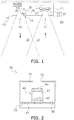
- FIG. 1 schematically illustrates an indoor unit 10 of an air conditioner according to the present invention.
- the indoor unit 10 is installed on a ceiling, a wall, or another location of a room which is a space 90 to be air-conditioned.
- the indoor unit 10 includes a housing 11.
- An inlet port 17 through which air is drawn in from the space 90 to be air-conditioned and a blow-out port 18 through which air is blown out into the space 90 to be air-conditioned are formed on the housing 11 or the decorative panel 15. Air blown out through the blow-out port 18 and air drawn in through the inlet port 17 pass through an area which is referred to as an air flow area 70. Relatively strong wind is generated in the air flow area 70.
- a refrigerant flow path member 20, a fan 23, and a refrigerant detection sensor 30 are disposed inside the housing 11.
- the refrigerant flow path member 20 of the indoor unit 10 constitutes a refrigerant circuit together with an outdoor unit (not illustrated).
- a flammable refrigerant may circulate through the refrigerant circuit.
- the flammable refrigerant may be a mildly flammable refrigerant.
- the refrigerant flow path member 20 includes a heat exchanger 21 and a refrigerant pipe 22.
- the heat exchanger 21 exchanges heat between the refrigerant flowing through the refrigerant pipe 22 and air.
- the refrigerant can be in various states such as a gas state, a gas-liquid two-phase state, and a liquid state.
- the fan 23 draws in air through the inlet port 17, facilitates heat transfer between the air and the refrigerant in the heat exchanger 21, and blows out the air through the blow-out port 18.
- the fan 23 is controlled by a control circuit 51.
- the refrigerant detection sensor 30 is used for detecting refrigerant gas leaking from the refrigerant flow path member 20 into the space 90 to be air-conditioned. In other words, it is not a sole object of the refrigerant detection sensor 30 to detect leaked refrigerant gas accumulated inside the housing 11.
- the housing 11 or the decorative panel 15 is preferably provided with an opening 16 facing the space 90 to be air-conditioned so that the refrigerant detection sensor 30 can be mounted.
- the opening 16 for leaked refrigerant detection by the refrigerant detection sensor 30 is preferably separately provided rather than using the inlet port 17 or the blow-out port 18 as the opening 16.
- An output signal of the refrigerant detection sensor 30 is transmitted to a reception circuit 52 by wired communication or wireless communication and then processed by the control circuit 51 which is connected to the reception circuit 52.
- a battery 53 for power supply may be connected to the refrigerant detection sensor 30.
- a part of the refrigerant detection sensor 30 disposed inside the air flow area 70 is referred to as an inside-air-flow-area part 35.
- a part of the refrigerant detection sensor 30 disposed outside the air flow area 70 is referred to as an outside-air-flow-area part 36.
- the refrigerant detection sensor 30 at least includes the outside-air-flow-area part 36.
- the entire refrigerant detection sensor 30 may be the outside-air-flow-area part 36.
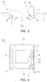
- FIG. 2 is an example of the structure of the refrigerant detection sensor 30.
- the refrigerant detection sensor 30 includes a casing 31, a circuit board 37, and a sensor unit 40.
- the casing 31 houses the circuit board 37 and the sensor unit 40.
- the casing 31 is formed with a gas intake port 32 for taking in refrigerant gas and a circuit board support 33 for supporting the circuit board 37.
- the sensor unit 40 is disposed on the circuit board 37.
- At least a part of the casing 31 may be constituted of the housing 11 or the decorative panel 15. In this case, for example, the opening 16 and the gas intake port 32 may be the same port.
- the refrigerant detection sensor 30 is disposed in a manner such that the opening 16 for leaked refrigerant detection on the housing 11 or the decorative panel 15 communicates with the gas intake port 32 of the refrigerant detection sensor 30.
- the sensor unit 40 includes a sensor cover 41, a sensor element 42, and a filter 45.
- the sensor element 42 is configured to detect refrigerant gas. For example, a resistance value of the sensor element 42 changes according to the concentration of refrigerant gas.
- the sensor element 42 is mounted on the circuit board 37.
- the sensor cover 41 guides refrigerant gas so that the refrigerant gas passes through the filter 45 before arriving at the sensor element 42.
- At least a part of the sensor cover 41 may be constituted of the housing 11 or the decorative panel 15. Alternatively, at least a part of the sensor cover 41 may be constituted of the casing 31.
- the outside-air-flow-area part 36 of the refrigerant detection sensor 30 is set to include the gas intake port 32.
- the outside-air-flow-area part 36 may further include the filter 45 or the sensor element 42.
- the filter 45 In a case where the filter 45 is disposed on substantially the same plane as the housing 11 or the decorative panel 15, the filter 45 itself serves as the gas intake port 32.
- the gas intake port 32 is disposed outside the air flow area 70. Thus, air itself or a foreign matter which may damage the refrigerant detection sensor 30 is restrained from entering the inside of the refrigerant detection sensor 30 through the gas intake port 32, which facilitates maintaining the lifetime of the refrigerant detection sensor 30.
- the filter 45 or the sensor element 42 may also be disposed outside the air flow area 70. In this case, air itself or a foreign matter is prevented from damaging the filter 45 or the sensor element 42.
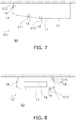
- FIGS. 3 and 4 illustrate an indoor unit 10A according to a first embodiment of the present invention.
- the indoor unit 10A is a ceiling-embedded cassette type four-direction blow-out indoor unit.
- the indoor unit 10A is embedded in a ceiling C.
- a housing 11 is provided with a decorative panel 15 and a flap 19.
- the flap 19 is disposed at each blow-out port 18, and swings in the range of a central angle ⁇ to change the blow-out direction of air.
- An air flow area 70 is inside the central angle ⁇ which defines the swing range of the flap 19.
- a refrigerant detection sensor 30 is disposed at a place S1, a place S2, a place S3, or a place S4.
- the place S1, the place S2, the place S3, and the place S4 are all located outside the central angle ⁇ .
- the place S1 is located between two adjacent blow-out ports 18.
- the place S2 is located between the blow-out port 18 and an inlet port 17.
- the place S3 is located adjacent to the blow-out port 18 at a position displaced from the blow-out port 18 in the longitudinal direction of the blow-out port 18.
- the place S4 is located at an opening 16 on the decorative panel 15 other than the blow-out port 18 and the inlet port 17 in a manner similar to the places S1 to S3.
- an outside-air-flow-area part 36 of the refrigerant detection sensor 30 is disposed outside the swing range of the flap 19.
- the wind or the like is restrained from hitting the refrigerant detection sensor 30 due to the action of the flap 19.
- the outside-air-flow-area part 36 of the refrigerant detection sensor 30 is disposed between the plurality of blow-out ports 18.
- the refrigerant detection sensor 30 is disposed off a route of wind blown out through each of the blow-out ports 18. Therefore, the wind is less likely to hit the refrigerant detection sensor 30.
- the outside-air-flow-area part 36 of the refrigerant detection sensor 30 is disposed between the blow-out port 18 and the inlet port 17.
- the refrigerant detection sensor 30 is disposed off a route of wind blown out through the blow-out port 18 and a route of wind drawn in through the inlet port 17. Therefore, the wind is less likely to hit the refrigerant detection sensor 30.
- the outside-air-flow-area part 36 of the refrigerant detection sensor 30 is disposed adjacent to the blow-out port 18 at the position displaced from the blow-out port 18 in the longitudinal direction of the blow-out port 18.
- the refrigerant detection sensor 30 is disposed off wind blown out through the blow-out port 18. Therefore, the wind is less likely to hit the refrigerant detection sensor 30.
- the outside-air-flow-area part 36 of the refrigerant detection sensor 30 is disposed at the opening 16 on the decorative panel 15 other than the blow-out port 18 and the inlet port 17.
- the refrigerant detection sensor 30 can be disposed off the blow-out port 18 or the inlet port 17. Therefore, the wind is less likely to hit the refrigerant detection sensor 30.
- a gas intake port 32 may be disposed lower than both the inlet port 17 and the blow-out port 18 through which the refrigerant gas may leak out.
- the detection performance is improved.
- FIG. 5 illustrates an indoor unit 10B according to a second embodiment of the present invention.
- the indoor unit 10B is a ceiling-embedded cassette type single-flow indoor unit.
- the indoor unit 10B is embedded in a ceiling in a manner similar to the indoor unit 10A according to the first embodiment.
- a housing 11 is provided with one inlet port 17 and one blow-out port 18.
- a refrigerant detection sensor 30 is disposed at a place S5 or a place S6.
- the place S5 is disposed adjacent to the blow-out port 18 at a position displaced from the blow-out port 18 in the longitudinal direction of the blow-out port 18.
- the place S6 is located between the blow-out port 18 and the inlet port 17.
- Each of the places S5 and S6 is located at an opening 16 on the housing 11 other than the blow-out port 18 and the inlet port 17.
- an outside-air-flow-area part 36 of the refrigerant detection sensor 30 is located adjacent to the blow-out port 18 at the position displaced from the blow-out port 18 in the longitudinal direction of the blow-out port 18.
- the refrigerant detection sensor 30 is disposed off wind blown out through the blow-out port 18. Therefore, the wind is less likely to hit the refrigerant detection sensor 30.
- the outside-air-flow-area part 36 of the refrigerant detection sensor 30 is disposed between the blow-out port 18 and the inlet port 17.
- the refrigerant detection sensor 30 is disposed off a route of wind blown out through the blow-out port 18 and a route of wind drawn in through the inlet port 17. Therefore, the wind is less likely to hit the refrigerant detection sensor 30.
- the outside-air-flow-area part 36 of the refrigerant detection sensor 30 is disposed at the opening 16 on the housing 11 other than the blow-out port 18 and the inlet port 17.
- the refrigerant detection sensor 30 can be disposed off the blow-out port 18 or the inlet port 17. Therefore, the wind is less likely to hit the refrigerant detection sensor 30.
- FIG. 6 illustrates an indoor unit 10C according to a third embodiment of the present invention.
- the indoor unit 10C is a ceiling-embedded cassette type double-flow indoor unit.
- the indoor unit 10C is embedded in a ceiling in a manner similar to the indoor unit 10A according to the first embodiment.
- a housing 11 is provided with two inlet ports 17 and two blow-out ports 18.
- a refrigerant detection sensor 30 is disposed at a place S7, a place S8, or a place S9.
- the place S7 is located between the blow-out port 18 and the inlet port 17.
- the place S8 is located between the two adjacent inlet ports 17.
- the place S9 is located adjacent to the blow-out port 18 at a position displaced from the blow-out port 18 in the longitudinal direction of the blow-out port 18.
- Each of the places S7 to S9 is located at an opening 16 on the housing 11 other than the blow-out port 18 and the inlet port 17.
- an outside-air-flow-area part 36 of the refrigerant detection sensor 30 is disposed between the plurality of inlet ports 17.
- the refrigerant detection sensor 30 is disposed off a route of wind drawn in through each of the inlet ports 17. Therefore, the wind is less likely to hit the refrigerant detection sensor 30.
- FIG. 7 illustrates an indoor unit 10D according to a fourth embodiment of the present invention.
- the indoor unit 10D is a ceiling-suspended type one-direction blow-out indoor unit.
- the indoor unit 10D is installed in contact with a ceiling C.
- a refrigerant detection sensor 30 is disposed at a place S10, a place S11, or a place S12.
- Each of the places S10 and S11 is located between a blow-out port 18 and an inlet port 17.
- the place S12 is located on the opposite side of the inlet port 17 with respect to the blow-out port 18.
- Each of the places S10 to S12 is located at an opening 16 on a housing 11 other than the blow-out port 18 and the inlet port 17.
- an outside-air-flow-area part 36 of the refrigerant detection sensor 30 is disposed on the opposite side of the inlet port 17 with respect to the blow-out port 18.
- the refrigerant detection sensor 30 is disposed off a route of wind blown out through the blow-out port 18 and a route of wind drawn in through the inlet port 17. Therefore, the wind is less likely to hit the refrigerant detection sensor 30.
- FIGS. 8 and 9 illustrate an indoor unit 10E according to a fifth embodiment of the present invention.
- the indoor unit 10D is a ceiling-suspended type four-direction blow-out indoor unit.
- the indoor unit 10E is installed in contact with a ceiling C in a manner similar to the indoor unit 10D according to the fourth embodiment.
- a housing 11 is provided with one inlet port 17 and four blow-out ports 18.
- a refrigerant detection sensor 30 is disposed at a place S13 or a place S14.
- the place S13 is located between the blow-out port 18 and the inlet port 17.
- the place S14 is located on the opposite side of the inlet port 17 with respect to the blow-out port 18.
- Each of the places S13 and S14 is located at an opening 16 on the housing 11 other than the blow-out port 18 and the inlet port 17.
- FIG. 10 illustrates an indoor unit 10F according to a sixth embodiment of the present invention.
- the indoor unit 10F is a wall-mounted type indoor unit.
- the indoor unit 10F is installed in contact with a wall W.
- a housing 11 is provided with a flap 19.
- the flap 19 is disposed on a blow-out port 18, and swings in the range of a central angle ⁇ to change the blow-out direction of air.
- An air flow area 70 is inside the central angle ⁇ which defines the swing range of the flap 19.
- a refrigerant detection sensor 30 is disposed at a place S15, a place S16, or a place S17.
- the place S15, the place S16, and the place S17 are all located outside the central angle ⁇ .
- the place S15 is located on the opposite side of the blow-out port 18 with respect to an inlet port 17.
- the place S18 is located between the blow-out port 18 and the inlet port 17.
- the place S17 is located on the opposite side of the inlet port 17 with respect to the blow-out port 18.
- Each of the places S15 to S17 is located at an opening 16 on the housing 11 other than the blow-out port 18 and the inlet port 17.
- an outside-air-flow-area part 36 of the refrigerant detection sensor 30 is disposed on the opposite side of the blow-out port 18 with respect to the inlet port 17.
- the refrigerant detection sensor 30 is disposed off a route of wind blown out through the blow-out port 18 and a route of wind drawn in through the inlet port 17. Therefore, the wind is less likely to hit the refrigerant detection sensor 30.
- FIG. 11 illustrates an indoor unit 10G according to a seventh embodiment of the present invention.
- the indoor unit 10G is a duct type indoor unit.
- the indoor unit 10G includes a blow-out port 18 which is disposed on the tip of a duct.
- a refrigerant detection sensor 30 is disposed at a place S18 or a place S19.
- the place S18 is located on the side face of the duct including the blow-out port 18.
- the place S19 is located on the duct which is disposed on a ceiling.
- an outside-air-flow-area part 36 of the refrigerant detection sensor 30 is disposed on the side face of the duct including the blow-out port 18.
- the refrigerant detection sensor 30 can be disposed off the blow-out port 18 or an inlet port 17. Therefore, the wind is less likely to hit the refrigerant detection sensor 30.
- the outside-air-flow-area part 36 of the refrigerant detection sensor 30 is disposed on the duct which is disposed on the ceiling.
- the refrigerant detection sensor 30 can be disposed off the blow-out port 18 or the inlet port 17. Therefore, the wind is less likely to hit the refrigerant detection sensor 30.
- Patent Literature 1 JP H08-178397 A
Landscapes
- Engineering & Computer Science (AREA)
- Mechanical Engineering (AREA)
- General Engineering & Computer Science (AREA)
- Chemical & Material Sciences (AREA)
- Combustion & Propulsion (AREA)
- Physics & Mathematics (AREA)
- Thermal Sciences (AREA)
- Air Conditioning Control Device (AREA)
- Air Filters, Heat-Exchange Apparatuses, And Housings Of Air-Conditioning Units (AREA)
Abstract
Description
- The present invention relates to an indoor unit of an air conditioning apparatus, the indoor unit including a refrigerant detection sensor.
- In order to stop the operation of an air conditioning apparatus when a refrigerant leaks out of the air conditioning apparatus, the air conditioning apparatus may be equipped with a refrigerant detection sensor. An air conditioning apparatus disclosed in Patent Literature 1 (
JP H08-178397 A - In a case where the refrigerant detection sensor and the indoor unit are separated from each other in this manner, a installation burden is large when the air conditioning apparatus is installed in the room. Thus, the refrigerant detection sensor is desirably integrated with the indoor unit.
- A blow-out port for air is present on the indoor unit. Air itself which enters and leaves the indoor unit and a foreign matter carried by the air hit the refrigerant detection sensor depending on the installed place of the refrigerant detection sensor in the indoor unit. Thus, there is a possibility that the lifetime of the refrigerant detection sensor is shortened due to damage.
- It is an object of the present invention to maintain the lifetime of a refrigerant detection sensor in an indoor unit of an air conditioning apparatus.
- An indoor unit according to a first aspect of the present invention includes a blow-out port through which air is blown out into a space to be air-conditioned, a refrigerant flow path member through which flammable refrigerant gas flows, and a refrigerant detection sensor configured to detect the refrigerant gas leaking out of the refrigerant flow path member. The refrigerant detection sensor is disposed facing the space to be air-conditioned. The refrigerant detection sensor includes a casing. The casing includes a gas intake port for taking in the refrigerant gas. The refrigerant detection sensor includes an outside-air-flow-area part disposed outside an air flow area through which the air blown out through the blow-out port passes. The outside-air-flow-area part includes the gas intake port.
- In this configuration, the gas intake port is disposed outside the air flow area. Thus, air itself or a foreign matter which may damage the refrigerant detection sensor is restrained from entering the inside of the refrigerant detection sensor through the gas intake port, which facilitates maintaining the lifetime of the refrigerant detection sensor.
- An indoor unit according to a second aspect of the present invention is the indoor unit according to the first aspect in which the refrigerant detection sensor further includes a sensor element configured to detect the refrigerant gas and a filter through which the refrigerant gas passes before arriving at the sensor element. The outside-air-flow-area part includes the filter.
- In this configuration, the filter is disposed outside the air flow area. Thus, air itself or a foreign matter is restrained from damaging the filter.
- An indoor unit according to a third aspect of the present invention is the indoor unit according to the second aspect in which the outside-air-flow-area part includes the sensor element.
- In this configuration, the sensor element is disposed outside the air flow area. Thus, air itself or the like is restrained from damaging the sensor element.
- An indoor unit according to a fourth aspect of the present invention is the indoor unit according to any one of the first to third aspects further including a flap disposed on the blow-out port and configured to swing to change a blow-out direction of the air. The air flow area is inside a central angle defining a swing range of the flap.
- In this configuration, the outside-air-flow-area part of the refrigerant detection sensor is disposed outside the swing range of the flap. Thus, the action of the flap restrains air or the like from hitting the refrigerant detection sensor.
- An indoor unit according to a fifth aspect of the present invention is the indoor unit according to any one of the first to fourth aspects in which the outside-air-flow-area part is disposed adjacent to the blow-out port at a position displaced from the blow-out port in a longitudinal direction of the blow-out port.
- In this configuration, the outside-air-flow-area part of the refrigerant detection sensor is disposed adjacent to the blow-out port at the position displaced from the blow-out port in the longitudinal direction of the blow-out port. Thus, the refrigerant detection sensor is disposed off wind blown out through the blow-out port. Therefore, the wind is less likely to hit the refrigerant detection sensor.
- An indoor unit according to a sixth aspect of the present invention is the indoor unit according to any one of the first to fifth aspects in which the outside-air-flow-area part is disposed between a plurality of the blow-out ports.
- In this configuration, the outside-air-flow-area part of the refrigerant detection sensor is disposed between the plurality of blow-out ports. Thus, the refrigerant detection sensor is disposed off a route of wind blown out through each of the blow-out ports. Therefore, the wind is less likely to hit the refrigerant detection sensor.
- An indoor unit according to a seventh aspect of the present invention is the indoor unit according to any one of the first to sixth aspects further including an inlet port through which the air is drawn in from the space to be air-conditioned. The air drawn in through the inlet port passes through the air flow area.
- In this configuration, the air drawn in through the inlet port passes through the air flow area. Thus, the air drawn in through the inlet port is restrained from damaging the refrigerant detection sensor.
- An indoor unit according to an eighth aspect of the present invention is the indoor unit according to the seventh aspect in which the gas intake port is disposed at a position lower than a lowest one of the inlet port and the blow-out port.
- In this configuration, the gas intake port is disposed lower than the openings of the indoor unit through which the refrigerant gas may leak out. Thus, when the refrigerant gas has a specific gravity higher than air, the detection performance is improved.
- An indoor unit according to an ninth aspect of the present invention is the indoor unit according to the seventh or eighth aspect in which the outside-air-flow-area part is disposed between the blow-out port and the inlet port.
- In this configuration, the outside-air-flow-area part of the refrigerant detection sensor is disposed between the blow-out port and the inlet port. Thus, the refrigerant detection sensor is disposed off a route of wind blown out through the blow-out port and a route of wind drawn in through the inlet port. Therefore, the wind is less likely to hit the refrigerant detection sensor.
- An indoor unit according to a tenth aspect of the present invention is the indoor unit according to any one of the seventh to ninth aspects in which the outside-air-flow-area part is disposed on an opposite side of the inlet port with respect to the blow-out port.
- In this configuration, the outside-air-flow-area part of the refrigerant detection sensor is disposed on the opposite side of the inlet port with respect to the blow-out port. Thus, the refrigerant detection sensor is disposed off a route of wind blown out through the blow-out port and a route of wind drawn in through the inlet port. Therefore, the wind is less likely to hit the refrigerant detection sensor.
- An indoor unit according to an eleventh aspect of the present invention is the indoor unit according to any one of the seventh to tenth aspects in which the outside-air-flow-area part is disposed on an opposite side of the blow-out port with respect to the inlet port.
- In this configuration, the outside-air-flow-area part of the refrigerant detection sensor is disposed on the opposite side of the blow-out port with respect to the inlet port. Thus, the refrigerant detection sensor is disposed off a route of wind blown out through the blow-out port and a route of wind drawn in through the inlet port. Therefore, the wind is less likely to hit the refrigerant detection sensor.
- An indoor unit according to a twelfth aspect of the present invention is the indoor unit according to any one of the seventh to eleventh aspects in which the outside-air-flow-area part is disposed between a plurality of the inlet ports.
- In this configuration, the outside-air-flow-area part of the refrigerant detection sensor is disposed between the plurality of inlet ports. Thus, the refrigerant detection sensor is disposed off a route of wind drawn in through each of the inlet ports. Therefore, the wind is less likely to hit the refrigerant detection sensor.
- An indoor unit according to a thirteenth aspect of the present invention is the indoor unit according to any one of the seventh to twelfth aspects further including a housing configured to house the refrigerant flow path member. The outside-air-flow-area part is disposed on an opening on the housing other than the blow-out port and the inlet port.
- In this configuration, the outside-air-flow-area part of the refrigerant detection sensor is disposed on the opening on the housing other than the blow-out port and the inlet port. Thus, the refrigerant detection sensor can be disposed off the blow-out port or the inlet port. Therefore, the wind is less likely to hit the refrigerant detection sensor.
- An indoor unit according to a fourteenth aspect of the present invention is the indoor unit according to any one of the seventh to twelfth aspects further including a decorative panel disposed facing the space to be air-conditioned. The outside-air-flow-area part is disposed on an opening on the decorative panel other than the blow-out port and the inlet port.
- In this configuration, the outside-air-flow-area part of the refrigerant detection sensor is disposed on the opening on the decorative panel other than the blow-out port and the inlet port. Thus, the refrigerant detection sensor can be disposed off the blow-out port or the inlet port. Therefore, the wind is less likely to hit the refrigerant detection sensor.
- The indoor units according to the first to seventh aspects and the ninth to fourteenth aspects of the present invention facilitate maintaining the lifetime of the refrigerant detection sensor.
- The indoor unit according to the eighth aspect of the present invention improves the refrigerant detection performance when the refrigerant gas has a specific gravity higher than air.
-
-
FIG. 1 is a schematic view of a basic configuration of anindoor unit 10 according to the present invention. -
FIG. 2 is a schematic view of an example of the structure of arefrigerant detection sensor 30 which is mounted on theindoor unit 10. -
FIG. 3 is a side sectional view of anindoor unit 10A according to a first embodiment of the present invention. -
FIG. 4 is a bottom view of theindoor unit 10A according to the first embodiment of the present invention. -
FIG. 5 is a bottom view of anindoor unit 10B according to a second embodiment of the present invention. -
FIG. 6 is a bottom view of anindoor unit 10C according to a third embodiment of the present invention. -
FIG. 7 is a side sectional view of anindoor unit 10D according to a fourth embodiment of the present invention. -
FIG. 8 is a side sectional view of anindoor unit 10E according to a fifth embodiment of the present invention. -
FIG. 9 is a bottom view of theindoor unit 10E according to the fifth embodiment of the present invention. -
FIG. 10 is a side sectional view of anindoor unit 10F according to a sixth embodiment of the present invention. -
FIG. 11 is a schematic view of anindoor unit 10G according to a seventh embodiment of the present invention. -
FIG. 1 schematically illustrates anindoor unit 10 of an air conditioner according to the present invention. Theindoor unit 10 is installed on a ceiling, a wall, or another location of a room which is aspace 90 to be air-conditioned. Theindoor unit 10 includes ahousing 11. Adecorative panel 15, which gives a good appearance for a user present in thespace 90 to be air-conditioned, may be attached to thehousing 11. Aninlet port 17 through which air is drawn in from thespace 90 to be air-conditioned and a blow-outport 18 through which air is blown out into thespace 90 to be air-conditioned are formed on thehousing 11 or thedecorative panel 15. Air blown out through the blow-outport 18 and air drawn in through theinlet port 17 pass through an area which is referred to as anair flow area 70. Relatively strong wind is generated in theair flow area 70. A refrigerantflow path member 20, afan 23, and arefrigerant detection sensor 30 are disposed inside thehousing 11. - The refrigerant
flow path member 20 of theindoor unit 10 constitutes a refrigerant circuit together with an outdoor unit (not illustrated). A flammable refrigerant may circulate through the refrigerant circuit. For example, the flammable refrigerant may be a mildly flammable refrigerant. The refrigerantflow path member 20 includes aheat exchanger 21 and arefrigerant pipe 22. Theheat exchanger 21 exchanges heat between the refrigerant flowing through therefrigerant pipe 22 and air. When the refrigerant flows through the refrigerantflow path member 20, the refrigerant can be in various states such as a gas state, a gas-liquid two-phase state, and a liquid state. - The
fan 23 draws in air through theinlet port 17, facilitates heat transfer between the air and the refrigerant in theheat exchanger 21, and blows out the air through the blow-outport 18. Thefan 23 is controlled by a control circuit 51. - The
refrigerant detection sensor 30 is used for detecting refrigerant gas leaking from the refrigerantflow path member 20 into thespace 90 to be air-conditioned. In other words, it is not a sole object of therefrigerant detection sensor 30 to detect leaked refrigerant gas accumulated inside thehousing 11. In order to detect the leakage of refrigerant gas into thespace 90 to be air-conditioned, thehousing 11 or thedecorative panel 15 is preferably provided with anopening 16 facing thespace 90 to be air-conditioned so that therefrigerant detection sensor 30 can be mounted. Theopening 16 for leaked refrigerant detection by therefrigerant detection sensor 30 is preferably separately provided rather than using theinlet port 17 or the blow-outport 18 as theopening 16. - An output signal of the
refrigerant detection sensor 30 is transmitted to a reception circuit 52 by wired communication or wireless communication and then processed by the control circuit 51 which is connected to the reception circuit 52. When wireless communication is performed, abattery 53 for power supply may be connected to therefrigerant detection sensor 30. - As illustrated in
FIG. 1 , a part of therefrigerant detection sensor 30 disposed inside theair flow area 70 is referred to as an inside-air-flow-area part 35. On the other hand, a part of therefrigerant detection sensor 30 disposed outside theair flow area 70 is referred to as an outside-air-flow-area part 36. In the present invention, therefrigerant detection sensor 30 at least includes the outside-air-flow-area part 36. For example, the entirerefrigerant detection sensor 30 may be the outside-air-flow-area part 36. -
FIG. 2 is an example of the structure of therefrigerant detection sensor 30. Therefrigerant detection sensor 30 includes acasing 31, acircuit board 37, and asensor unit 40. The casing 31 houses thecircuit board 37 and thesensor unit 40. Thecasing 31 is formed with agas intake port 32 for taking in refrigerant gas and acircuit board support 33 for supporting thecircuit board 37. Thesensor unit 40 is disposed on thecircuit board 37. At least a part of thecasing 31 may be constituted of thehousing 11 or thedecorative panel 15. In this case, for example, theopening 16 and thegas intake port 32 may be the same port. On the other hand, in a case where thehousing 11 or thedecorative panel 15 is separated from thecasing 31, therefrigerant detection sensor 30 is disposed in a manner such that theopening 16 for leaked refrigerant detection on thehousing 11 or thedecorative panel 15 communicates with thegas intake port 32 of therefrigerant detection sensor 30. - The
sensor unit 40 includes asensor cover 41, asensor element 42, and afilter 45. Thesensor element 42 is configured to detect refrigerant gas. For example, a resistance value of thesensor element 42 changes according to the concentration of refrigerant gas. Thesensor element 42 is mounted on thecircuit board 37. Thesensor cover 41 guides refrigerant gas so that the refrigerant gas passes through thefilter 45 before arriving at thesensor element 42. At least a part of thesensor cover 41 may be constituted of thehousing 11 or thedecorative panel 15. Alternatively, at least a part of thesensor cover 41 may be constituted of thecasing 31. - The outside-air-flow-
area part 36 of therefrigerant detection sensor 30 is set to include thegas intake port 32. The outside-air-flow-area part 36 may further include thefilter 45 or thesensor element 42. - In a case where the
filter 45 is disposed on substantially the same plane as thehousing 11 or thedecorative panel 15, thefilter 45 itself serves as thegas intake port 32. - The
gas intake port 32 is disposed outside theair flow area 70. Thus, air itself or a foreign matter which may damage therefrigerant detection sensor 30 is restrained from entering the inside of therefrigerant detection sensor 30 through thegas intake port 32, which facilitates maintaining the lifetime of therefrigerant detection sensor 30. - The
filter 45 or thesensor element 42 may also be disposed outside theair flow area 70. In this case, air itself or a foreign matter is prevented from damaging thefilter 45 or thesensor element 42. -
FIGS. 3 and 4 illustrate anindoor unit 10A according to a first embodiment of the present invention. Theindoor unit 10A is a ceiling-embedded cassette type four-direction blow-out indoor unit. Theindoor unit 10A is embedded in a ceilingC. A housing 11 is provided with adecorative panel 15 and aflap 19. Theflap 19 is disposed at each blow-outport 18, and swings in the range of a central angle θ to change the blow-out direction of air. Anair flow area 70 is inside the central angle θ which defines the swing range of theflap 19. - For example, a
refrigerant detection sensor 30 is disposed at a place S1, a place S2, a place S3, or a place S4. The place S1, the place S2, the place S3, and the place S4 are all located outside the central angle θ. The place S1 is located between two adjacent blow-outports 18. The place S2 is located between the blow-outport 18 and aninlet port 17. The place S3 is located adjacent to the blow-outport 18 at a position displaced from the blow-outport 18 in the longitudinal direction of the blow-outport 18. The place S4 is located at anopening 16 on thedecorative panel 15 other than the blow-outport 18 and theinlet port 17 in a manner similar to the places S1 to S3. - Regarding each of the places S1 to S4, an outside-air-flow-
area part 36 of therefrigerant detection sensor 30 is disposed outside the swing range of theflap 19. Thus, the wind or the like is restrained from hitting therefrigerant detection sensor 30 due to the action of theflap 19. - Regarding the place S1, the outside-air-flow-
area part 36 of therefrigerant detection sensor 30 is disposed between the plurality of blow-outports 18. Thus, therefrigerant detection sensor 30 is disposed off a route of wind blown out through each of the blow-outports 18. Therefore, the wind is less likely to hit therefrigerant detection sensor 30. - Regarding the place S2, the outside-air-flow-
area part 36 of therefrigerant detection sensor 30 is disposed between the blow-outport 18 and theinlet port 17. Thus, therefrigerant detection sensor 30 is disposed off a route of wind blown out through the blow-outport 18 and a route of wind drawn in through theinlet port 17. Therefore, the wind is less likely to hit therefrigerant detection sensor 30. - Regarding the place S3, the outside-air-flow-
area part 36 of therefrigerant detection sensor 30 is disposed adjacent to the blow-outport 18 at the position displaced from the blow-outport 18 in the longitudinal direction of the blow-outport 18. Thus, therefrigerant detection sensor 30 is disposed off wind blown out through the blow-outport 18. Therefore, the wind is less likely to hit therefrigerant detection sensor 30. - Regarding each of the places S1 to S4, the outside-air-flow-
area part 36 of therefrigerant detection sensor 30 is disposed at theopening 16 on thedecorative panel 15 other than the blow-outport 18 and theinlet port 17. Thus, therefrigerant detection sensor 30 can be disposed off the blow-outport 18 or theinlet port 17. Therefore, the wind is less likely to hit therefrigerant detection sensor 30. - For example, regarding the place S2, a
gas intake port 32 may be disposed lower than both theinlet port 17 and the blow-outport 18 through which the refrigerant gas may leak out. Thus, when the refrigerant gas has a specific gravity higher than air, the detection performance is improved. -
FIG. 5 illustrates anindoor unit 10B according to a second embodiment of the present invention. Theindoor unit 10B is a ceiling-embedded cassette type single-flow indoor unit. Theindoor unit 10B is embedded in a ceiling in a manner similar to theindoor unit 10A according to the first embodiment. Ahousing 11 is provided with oneinlet port 17 and one blow-outport 18. - For example, a
refrigerant detection sensor 30 is disposed at a place S5 or a place S6. The place S5 is disposed adjacent to the blow-outport 18 at a position displaced from the blow-outport 18 in the longitudinal direction of the blow-outport 18. The place S6 is located between the blow-outport 18 and theinlet port 17. Each of the places S5 and S6 is located at anopening 16 on thehousing 11 other than the blow-outport 18 and theinlet port 17. - Regarding the place S5, an outside-air-flow-
area part 36 of therefrigerant detection sensor 30 is located adjacent to the blow-outport 18 at the position displaced from the blow-outport 18 in the longitudinal direction of the blow-outport 18. Thus, therefrigerant detection sensor 30 is disposed off wind blown out through the blow-outport 18. Therefore, the wind is less likely to hit therefrigerant detection sensor 30. - Regarding the place S6, the outside-air-flow-
area part 36 of therefrigerant detection sensor 30 is disposed between the blow-outport 18 and theinlet port 17. Thus, therefrigerant detection sensor 30 is disposed off a route of wind blown out through the blow-outport 18 and a route of wind drawn in through theinlet port 17. Therefore, the wind is less likely to hit therefrigerant detection sensor 30. - Regarding each of the places S5 and S6, the outside-air-flow-
area part 36 of therefrigerant detection sensor 30 is disposed at theopening 16 on thehousing 11 other than the blow-outport 18 and theinlet port 17. Thus, therefrigerant detection sensor 30 can be disposed off the blow-outport 18 or theinlet port 17. Therefore, the wind is less likely to hit therefrigerant detection sensor 30. -
FIG. 6 illustrates anindoor unit 10C according to a third embodiment of the present invention. Theindoor unit 10C is a ceiling-embedded cassette type double-flow indoor unit. Theindoor unit 10C is embedded in a ceiling in a manner similar to theindoor unit 10A according to the first embodiment. Ahousing 11 is provided with twoinlet ports 17 and two blow-outports 18. - For example, a
refrigerant detection sensor 30 is disposed at a place S7, a place S8, or a place S9. The place S7 is located between the blow-outport 18 and theinlet port 17. The place S8 is located between the twoadjacent inlet ports 17. The place S9 is located adjacent to the blow-outport 18 at a position displaced from the blow-outport 18 in the longitudinal direction of the blow-outport 18. Each of the places S7 to S9 is located at anopening 16 on thehousing 11 other than the blow-outport 18 and theinlet port 17. - Regarding the place S8, an outside-air-flow-
area part 36 of therefrigerant detection sensor 30 is disposed between the plurality ofinlet ports 17. Thus, therefrigerant detection sensor 30 is disposed off a route of wind drawn in through each of theinlet ports 17. Therefore, the wind is less likely to hit therefrigerant detection sensor 30. - Regarding the place S7 and the place S9, effects similar to the effects described in the second embodiment are achieved.
-
FIG. 7 illustrates anindoor unit 10D according to a fourth embodiment of the present invention. Theindoor unit 10D is a ceiling-suspended type one-direction blow-out indoor unit. Theindoor unit 10D is installed in contact with a ceiling C. - For example, a
refrigerant detection sensor 30 is disposed at a place S10, a place S11, or a place S12. Each of the places S10 and S11 is located between a blow-outport 18 and aninlet port 17. The place S12 is located on the opposite side of theinlet port 17 with respect to the blow-outport 18. Each of the places S10 to S12 is located at anopening 16 on ahousing 11 other than the blow-outport 18 and theinlet port 17. - Regarding the place S12, an outside-air-flow-
area part 36 of therefrigerant detection sensor 30 is disposed on the opposite side of theinlet port 17 with respect to the blow-outport 18. Thus, therefrigerant detection sensor 30 is disposed off a route of wind blown out through the blow-outport 18 and a route of wind drawn in through theinlet port 17. Therefore, the wind is less likely to hit therefrigerant detection sensor 30. - Regarding the place S10 and the place S11, effects similar to the effects described in the second embodiment are achieved.
-
FIGS. 8 and9 illustrate anindoor unit 10E according to a fifth embodiment of the present invention. Theindoor unit 10D is a ceiling-suspended type four-direction blow-out indoor unit. Theindoor unit 10E is installed in contact with a ceiling C in a manner similar to theindoor unit 10D according to the fourth embodiment. Ahousing 11 is provided with oneinlet port 17 and four blow-outports 18. - For example, a
refrigerant detection sensor 30 is disposed at a place S13 or a place S14. The place S13 is located between the blow-outport 18 and theinlet port 17. The place S14 is located on the opposite side of theinlet port 17 with respect to the blow-outport 18. Each of the places S13 and S14 is located at anopening 16 on thehousing 11 other than the blow-outport 18 and theinlet port 17. - Regarding the place S13 and the place S14, effects similar to the effects described in the fourth embodiment are achieved.
-
FIG. 10 illustrates anindoor unit 10F according to a sixth embodiment of the present invention. Theindoor unit 10F is a wall-mounted type indoor unit. Theindoor unit 10F is installed in contact with a wallW. A housing 11 is provided with aflap 19. Theflap 19 is disposed on a blow-outport 18, and swings in the range of a central angle θ to change the blow-out direction of air. Anair flow area 70 is inside the central angle θ which defines the swing range of theflap 19. - For example, a
refrigerant detection sensor 30 is disposed at a place S15, a place S16, or a place S17. The place S15, the place S16, and the place S17 are all located outside the central angle θ. The place S15 is located on the opposite side of the blow-outport 18 with respect to aninlet port 17. The place S18 is located between the blow-outport 18 and theinlet port 17. The place S17 is located on the opposite side of theinlet port 17 with respect to the blow-outport 18. Each of the places S15 to S17 is located at anopening 16 on thehousing 11 other than the blow-outport 18 and theinlet port 17. - Regarding the place S15, an outside-air-flow-
area part 36 of therefrigerant detection sensor 30 is disposed on the opposite side of the blow-outport 18 with respect to theinlet port 17. Thus, therefrigerant detection sensor 30 is disposed off a route of wind blown out through the blow-outport 18 and a route of wind drawn in through theinlet port 17. Therefore, the wind is less likely to hit therefrigerant detection sensor 30. - Regarding the place S16 and the place S17, effects similar to the effects described in the fourth embodiment are achieved.
-
FIG. 11 illustrates anindoor unit 10G according to a seventh embodiment of the present invention. Theindoor unit 10G is a duct type indoor unit. Theindoor unit 10G includes a blow-outport 18 which is disposed on the tip of a duct. - For example, a
refrigerant detection sensor 30 is disposed at a place S18 or a place S19. The place S18 is located on the side face of the duct including the blow-outport 18. The place S19 is located on the duct which is disposed on a ceiling. - Regarding the place S18, an outside-air-flow-
area part 36 of therefrigerant detection sensor 30 is disposed on the side face of the duct including the blow-outport 18. Thus, therefrigerant detection sensor 30 can be disposed off the blow-outport 18 or aninlet port 17. Therefore, the wind is less likely to hit therefrigerant detection sensor 30. - Regarding the place S19, the outside-air-flow-
area part 36 of therefrigerant detection sensor 30 is disposed on the duct which is disposed on the ceiling. Thus, therefrigerant detection sensor 30 can be disposed off the blow-outport 18 or theinlet port 17. Therefore, the wind is less likely to hit therefrigerant detection sensor 30. -
- 10
- indoor unit
- 11
- housing
- 15
- decorative panel
- 17
- inlet port
- 18
- blow-out port
- 30
- refrigerant detection sensor
- 35
- inside-air-flow-area part
- 36
- outside-air-flow-area part
- 40
- sensor unit
- 70
- air flow area
- 90
- space to be air-conditioned
- C
- ceiling
- W
- wall
- Patent Literature 1:
JP H08-178397 A
Claims (14)
- An indoor unit (10) comprising:a blow-out port (18) through which air is blown out into a space (90) to be air-conditioned;a refrigerant flow path member (40) through which flammable refrigerant gas flows; anda refrigerant detection sensor (30) configured to detect the refrigerant gas leaking out of the refrigerant flow path member, whereinthe refrigerant detection sensor is disposed so as to face the space to be air-conditioned,the refrigerant detection sensor includes a casing (31),the casing includes a gas intake port (32) for taking in the refrigerant gas,the refrigerant detection sensor includes an outside-air-flow-area part (36) disposed outside an air flow area (70) through which the air blown out through the blow-out port passes, andthe outside-air-flow-area part includes the gas intake port.
- The indoor unit according to claim 1, whereinthe refrigerant detection sensor further includesa sensor element (42) configured to detect the refrigerant gas, anda filter (45) through which the refrigerant gas passes before arriving at the sensor element, andthe outside-air-flow-area part includes the filter.
- The indoor unit according to claim 2, wherein the outside-air-flow-area part includes the sensor element.
- The indoor unit according to any one of claims 1 to 3, further comprising a flap (19) disposed on the blow-out port and configured to swing to change a blow-out direction of the air, wherein
the air flow area is inside a central angle (θ) defining a swing range of the flap. - The indoor unit according to any one of claims 1 to 4, wherein the outside-air-flow-area part is disposed adjacent to the blow-out port at a position displaced from the blow-out port in a longitudinal direction of the blow-out port.
- The indoor unit according to any one of claims 1 to 5, wherein the outside-air-flow-area part is disposed between a plurality of the blow-out ports.
- The indoor unit according to any one of claims 1 to 6, further comprising an inlet port (17) through which the air is drawn in from the space to be air-conditioned, wherein
the air drawn in through the inlet port passes through the air flow area. - The indoor unit according to claim 7, wherein the gas intake port is disposed at a position lower than a lowest one of the inlet port and the blow-out port.
- The indoor unit according to claim 7 or 8, wherein the outside-air-flow-area part is disposed between the blow-out port and the inlet port.
- The indoor unit according to any one of claims 7 to 9, wherein the outside-air-flow-area part is disposed on an opposite side of the inlet port with respect to the blow-out port.
- The indoor unit according to any one of claims 7 to 10, wherein the outside-air-flow-area part is disposed on an opposite side of the blow-out port with respect to the inlet port.
- The indoor unit according to any one of claims 7 to 11, wherein the outside-air-flow-area part is disposed between a plurality of the inlet ports.
- The indoor unit according to any one of claims 7 to 12, further comprising a housing (11) configured to house the refrigerant flow path member, wherein
the outside-air-flow-area part is disposed at an opening (16) on the housing other than the blow-out port and the inlet port. - The indoor unit according to any one of claims 7 to 12, further comprising a decorative panel (15) disposed so as to face the space to be air-conditioned, wherein
the outside-air-flow-area part is disposed at an opening (16) on the decorative panel other than the blow-out port and the inlet port.
Applications Claiming Priority (2)
| Application Number | Priority Date | Filing Date | Title |
|---|---|---|---|
| JP2017135015A JP6658687B2 (en) | 2017-07-10 | 2017-07-10 | Indoor unit of an air conditioner having a refrigerant detection sensor |
| PCT/JP2018/025234 WO2019013049A1 (en) | 2017-07-10 | 2018-07-03 | Indoor unit for air conditioner comprising refrigerant detection sensor |
Publications (2)
| Publication Number | Publication Date |
|---|---|
| EP3653944A1 true EP3653944A1 (en) | 2020-05-20 |
| EP3653944A4 EP3653944A4 (en) | 2021-03-24 |
Family
ID=65002472
Family Applications (1)
| Application Number | Title | Priority Date | Filing Date |
|---|---|---|---|
| EP18831682.2A Pending EP3653944A4 (en) | 2017-07-10 | 2018-07-03 | INDOOR UNIT FOR AIR CONDITIONING WITH REFRIGERANT DETECTION SENSOR |
Country Status (5)
| Country | Link |
|---|---|
| US (1) | US20200393140A1 (en) |
| EP (1) | EP3653944A4 (en) |
| JP (1) | JP6658687B2 (en) |
| CN (1) | CN110637197B (en) |
| WO (1) | WO2019013049A1 (en) |
Cited By (1)
| Publication number | Priority date | Publication date | Assignee | Title |
|---|---|---|---|---|
| EP3940314A1 (en) * | 2020-07-16 | 2022-01-19 | Vaillant GmbH | Safety coil device for a heat pump |
Families Citing this family (16)
| Publication number | Priority date | Publication date | Assignee | Title |
|---|---|---|---|---|
| EP4528174A3 (en) * | 2017-04-06 | 2025-06-11 | Carrier Corporation | Moderate-to-low global warming potential value refrigerant leak detection |
| EP3910258B1 (en) * | 2019-01-09 | 2024-10-23 | Mitsubishi Electric Corporation | Air-conditioning apparatus |
| JP7504119B2 (en) * | 2019-04-29 | 2024-06-21 | 広東美的制冷設備有限公司 | Air conditioner indoor unit |
| US11662109B2 (en) | 2019-06-05 | 2023-05-30 | Carrier Corporation | Enclosure for gas detector |
| JP6922947B2 (en) * | 2019-07-12 | 2021-08-18 | ダイキン工業株式会社 | Indoor unit of refrigeration equipment |
| US11231198B2 (en) | 2019-09-05 | 2022-01-25 | Trane International Inc. | Systems and methods for refrigerant leak detection in a climate control system |
| ES2958825T3 (en) * | 2020-04-24 | 2024-02-15 | Daikin Ind Ltd | Refrigerant leak detection sensor for a heat pump and air conditioner that includes the same |
| US12104809B2 (en) * | 2021-04-26 | 2024-10-01 | Therm-O-Disc, Incorporated | Robust gas sensor for harsh environments |
| US12379308B2 (en) | 2021-09-30 | 2025-08-05 | Carrier Corporation | Environmental enclosure for a transport gas sensor |
| USD1027682S1 (en) | 2021-09-30 | 2024-05-21 | Carrier Corporation | Refrigerant detection sensor housing |
| US12253457B2 (en) | 2021-09-30 | 2025-03-18 | Carrier Corporation | Environmental enclosure for a transport gas sensor |
| US12487008B2 (en) | 2022-01-14 | 2025-12-02 | Trane International Inc. | Method of commissioning an HVAC system |
| CN114811844B (en) * | 2022-04-19 | 2023-07-18 | 美的集团武汉暖通设备有限公司 | Air conditioner operation control method, operation control device and air conditioner |
| JP2023167348A (en) * | 2022-05-11 | 2023-11-24 | 日本スピンドル製造株式会社 | Temperature control system and temperature control device |
| US12117191B2 (en) | 2022-06-24 | 2024-10-15 | Trane International Inc. | Climate control system with improved leak detector |
| JP2025035256A (en) * | 2023-09-01 | 2025-03-13 | 三菱重工サーマルシステムズ株式会社 | Indoor air conditioner |
Family Cites Families (10)
| Publication number | Priority date | Publication date | Assignee | Title |
|---|---|---|---|---|
| JPH08178397A (en) | 1994-12-26 | 1996-07-12 | Sanyo Electric Co Ltd | Air conditioner |
| JP4599699B2 (en) * | 2000-09-26 | 2010-12-15 | ダイキン工業株式会社 | Air conditioner |
| CN202675535U (en) * | 2012-01-18 | 2013-01-16 | 宁波奥克斯电气有限公司 | Air conditioning unit using R161 refrigerant |
| JP5665937B1 (en) * | 2013-09-13 | 2015-02-04 | 三菱電機株式会社 | Refrigeration cycle equipment |
| JP2016023809A (en) * | 2014-07-16 | 2016-02-08 | ダイキン工業株式会社 | Air conditioner |
| JP6412395B2 (en) * | 2014-10-14 | 2018-10-24 | 日立ジョンソンコントロールズ空調株式会社 | Air conditioner indoor unit |
| JP6448981B2 (en) * | 2014-10-23 | 2019-01-09 | 日立ジョンソンコントロールズ空調株式会社 | Air conditioner indoor unit |
| JP5987887B2 (en) * | 2014-10-31 | 2016-09-07 | ダイキン工業株式会社 | Air conditioner indoor unit |
| JP6248898B2 (en) * | 2014-10-31 | 2017-12-20 | ダイキン工業株式会社 | Air conditioner |
| JP6463478B2 (en) * | 2015-07-17 | 2019-02-06 | 三菱電機株式会社 | Air conditioner |
-
2017
- 2017-07-10 JP JP2017135015A patent/JP6658687B2/en active Active
-
2018
- 2018-07-03 EP EP18831682.2A patent/EP3653944A4/en active Pending
- 2018-07-03 WO PCT/JP2018/025234 patent/WO2019013049A1/en not_active Ceased
- 2018-07-03 US US16/616,560 patent/US20200393140A1/en not_active Abandoned
- 2018-07-03 CN CN201880032520.7A patent/CN110637197B/en active Active
Cited By (1)
| Publication number | Priority date | Publication date | Assignee | Title |
|---|---|---|---|---|
| EP3940314A1 (en) * | 2020-07-16 | 2022-01-19 | Vaillant GmbH | Safety coil device for a heat pump |
Also Published As
| Publication number | Publication date |
|---|---|
| WO2019013049A1 (en) | 2019-01-17 |
| CN110637197B (en) | 2020-10-09 |
| US20200393140A1 (en) | 2020-12-17 |
| JP6658687B2 (en) | 2020-03-04 |
| EP3653944A4 (en) | 2021-03-24 |
| JP2019015482A (en) | 2019-01-31 |
| CN110637197A (en) | 2019-12-31 |
Similar Documents
| Publication | Publication Date | Title |
|---|---|---|
| US20200393140A1 (en) | Air condtioning apparatus indoor unit including refrigerant detection sensor | |
| CN107110555B (en) | Indoor unit of air conditioner | |
| KR101691881B1 (en) | The ventilation and air conditioning systems for environment test equipment | |
| WO2015088225A1 (en) | Dehumidifier | |
| CN205783491U (en) | kitchen air conditioner | |
| US11796192B2 (en) | Air conditioning appliance with external make-up air module | |
| JP6653455B1 (en) | Indoor unit | |
| JP6906168B2 (en) | Indoor unit | |
| EP3604974A1 (en) | Heat exchanger and refrigeration device | |
| US11713901B2 (en) | Makeup air cross-flow energy recovery system atop air conditioner | |
| JP2004169966A (en) | Air conditioner test equipment | |
| CN114729758B (en) | Air conditioning system with supplementary air module | |
| WO2014175109A1 (en) | Air conditioner | |
| US20250283613A1 (en) | Window-type air conditioner | |
| CN106133451B (en) | Integrated air conditioner | |
| US20230228447A1 (en) | Air conditioner makeup air circulation | |
| WO2020077769A1 (en) | Detecting device and dehumidifying device having same | |
| CN107504597A (en) | Air-conditioner outdoor unit | |
| KR20080019357A (en) | Air conditioner | |
| EP4502481A1 (en) | Air conditioner | |
| JP2826256B2 (en) | Air conditioning and smoke exhaust system | |
| JP7539047B2 (en) | Indoor unit | |
| CN214199345U (en) | A gas detection thermostat | |
| KR20240169486A (en) | Air conditioner | |
| KR20240169489A (en) | Air Conditioner and Method for Removing an Air Conditioner Filter Module |
Legal Events
| Date | Code | Title | Description |
|---|---|---|---|
| STAA | Information on the status of an ep patent application or granted ep patent |
Free format text: STATUS: THE INTERNATIONAL PUBLICATION HAS BEEN MADE |
|
| PUAI | Public reference made under article 153(3) epc to a published international application that has entered the european phase |
Free format text: ORIGINAL CODE: 0009012 |
|
| STAA | Information on the status of an ep patent application or granted ep patent |
Free format text: STATUS: REQUEST FOR EXAMINATION WAS MADE |
|
| 17P | Request for examination filed |
Effective date: 20191223 |
|
| AK | Designated contracting states |
Kind code of ref document: A1 Designated state(s): AL AT BE BG CH CY CZ DE DK EE ES FI FR GB GR HR HU IE IS IT LI LT LU LV MC MK MT NL NO PL PT RO RS SE SI SK SM TR |
|
| AX | Request for extension of the european patent |
Extension state: BA ME |
|
| DAV | Request for validation of the european patent (deleted) | ||
| DAX | Request for extension of the european patent (deleted) | ||
| REG | Reference to a national code |
Ref country code: DE Ref legal event code: R079 Free format text: PREVIOUS MAIN CLASS: F24F0011490000 Ipc: F24F0013200000 |
|
| A4 | Supplementary search report drawn up and despatched |
Effective date: 20210222 |
|
| RIC1 | Information provided on ipc code assigned before grant |
Ipc: F24F 110/66 20180101ALN20210216BHEP Ipc: F24F 1/0068 20190101ALI20210216BHEP Ipc: F24F 13/20 20060101AFI20210216BHEP Ipc: F24F 11/36 20180101ALI20210216BHEP |
|
| RAP3 | Party data changed (applicant data changed or rights of an application transferred) |
Owner name: DAIKIN INDUSTRIES, LTD. |
|
| STAA | Information on the status of an ep patent application or granted ep patent |
Free format text: STATUS: EXAMINATION IS IN PROGRESS |
|
| 17Q | First examination report despatched |
Effective date: 20230504 |
|
| P01 | Opt-out of the competence of the unified patent court (upc) registered |
Effective date: 20230525 |