EP3653870A1 - Pitch bearing arrangement - Google Patents
Pitch bearing arrangement Download PDFInfo
- Publication number
- EP3653870A1 EP3653870A1 EP18205946.9A EP18205946A EP3653870A1 EP 3653870 A1 EP3653870 A1 EP 3653870A1 EP 18205946 A EP18205946 A EP 18205946A EP 3653870 A1 EP3653870 A1 EP 3653870A1
- Authority
- EP
- European Patent Office
- Prior art keywords
- bearing arrangement
- pitch bearing
- hub
- ring
- reinforcement
- Prior art date
- Legal status (The legal status is an assumption and is not a legal conclusion. Google has not performed a legal analysis and makes no representation as to the accuracy of the status listed.)
- Granted
Links
Images


Classifications
-
- F—MECHANICAL ENGINEERING; LIGHTING; HEATING; WEAPONS; BLASTING
- F03—MACHINES OR ENGINES FOR LIQUIDS; WIND, SPRING, OR WEIGHT MOTORS; PRODUCING MECHANICAL POWER OR A REACTIVE PROPULSIVE THRUST, NOT OTHERWISE PROVIDED FOR
- F03D—WIND MOTORS
- F03D1/00—Wind motors with rotation axis substantially parallel to the air flow entering the rotor
- F03D1/06—Rotors
- F03D1/065—Rotors characterised by their construction elements
- F03D1/0658—Arrangements for fixing wind-engaging parts to a hub
-
- F—MECHANICAL ENGINEERING; LIGHTING; HEATING; WEAPONS; BLASTING
- F03—MACHINES OR ENGINES FOR LIQUIDS; WIND, SPRING, OR WEIGHT MOTORS; PRODUCING MECHANICAL POWER OR A REACTIVE PROPULSIVE THRUST, NOT OTHERWISE PROVIDED FOR
- F03D—WIND MOTORS
- F03D80/00—Details, components or accessories not provided for in groups F03D1/00 - F03D17/00
- F03D80/70—Bearing or lubricating arrangements
-
- F—MECHANICAL ENGINEERING; LIGHTING; HEATING; WEAPONS; BLASTING
- F03—MACHINES OR ENGINES FOR LIQUIDS; WIND, SPRING, OR WEIGHT MOTORS; PRODUCING MECHANICAL POWER OR A REACTIVE PROPULSIVE THRUST, NOT OTHERWISE PROVIDED FOR
- F03D—WIND MOTORS
- F03D1/00—Wind motors with rotation axis substantially parallel to the air flow entering the rotor
- F03D1/06—Rotors
- F03D1/065—Rotors characterised by their construction elements
- F03D1/0691—Rotors characterised by their construction elements of the hub
-
- F—MECHANICAL ENGINEERING; LIGHTING; HEATING; WEAPONS; BLASTING
- F03—MACHINES OR ENGINES FOR LIQUIDS; WIND, SPRING, OR WEIGHT MOTORS; PRODUCING MECHANICAL POWER OR A REACTIVE PROPULSIVE THRUST, NOT OTHERWISE PROVIDED FOR
- F03D—WIND MOTORS
- F03D7/00—Controlling wind motors
- F03D7/02—Controlling wind motors the wind motors having rotation axis substantially parallel to the air flow entering the rotor
- F03D7/022—Adjusting aerodynamic properties of the blades
- F03D7/0224—Adjusting blade pitch
-
- F—MECHANICAL ENGINEERING; LIGHTING; HEATING; WEAPONS; BLASTING
- F16—ENGINEERING ELEMENTS AND UNITS; GENERAL MEASURES FOR PRODUCING AND MAINTAINING EFFECTIVE FUNCTIONING OF MACHINES OR INSTALLATIONS; THERMAL INSULATION IN GENERAL
- F16C—SHAFTS; FLEXIBLE SHAFTS; ELEMENTS OR CRANKSHAFT MECHANISMS; ROTARY BODIES OTHER THAN GEARING ELEMENTS; BEARINGS
- F16C33/00—Parts of bearings; Special methods for making bearings or parts thereof
- F16C33/30—Parts of ball or roller bearings
- F16C33/58—Raceways; Race rings
-
- F—MECHANICAL ENGINEERING; LIGHTING; HEATING; WEAPONS; BLASTING
- F05—INDEXING SCHEMES RELATING TO ENGINES OR PUMPS IN VARIOUS SUBCLASSES OF CLASSES F01-F04
- F05B—INDEXING SCHEME RELATING TO WIND, SPRING, WEIGHT, INERTIA OR LIKE MOTORS, TO MACHINES OR ENGINES FOR LIQUIDS COVERED BY SUBCLASSES F03B, F03D AND F03G
- F05B2260/00—Function
- F05B2260/70—Adjusting of angle of incidence or attack of rotating blades
- F05B2260/79—Bearing, support or actuation arrangements therefor
-
- F—MECHANICAL ENGINEERING; LIGHTING; HEATING; WEAPONS; BLASTING
- F16—ENGINEERING ELEMENTS AND UNITS; GENERAL MEASURES FOR PRODUCING AND MAINTAINING EFFECTIVE FUNCTIONING OF MACHINES OR INSTALLATIONS; THERMAL INSULATION IN GENERAL
- F16C—SHAFTS; FLEXIBLE SHAFTS; ELEMENTS OR CRANKSHAFT MECHANISMS; ROTARY BODIES OTHER THAN GEARING ELEMENTS; BEARINGS
- F16C2360/00—Engines or pumps
- F16C2360/31—Wind motors
-
- Y—GENERAL TAGGING OF NEW TECHNOLOGICAL DEVELOPMENTS; GENERAL TAGGING OF CROSS-SECTIONAL TECHNOLOGIES SPANNING OVER SEVERAL SECTIONS OF THE IPC; TECHNICAL SUBJECTS COVERED BY FORMER USPC CROSS-REFERENCE ART COLLECTIONS [XRACs] AND DIGESTS
- Y02—TECHNOLOGIES OR APPLICATIONS FOR MITIGATION OR ADAPTATION AGAINST CLIMATE CHANGE
- Y02E—REDUCTION OF GREENHOUSE GAS [GHG] EMISSIONS, RELATED TO ENERGY GENERATION, TRANSMISSION OR DISTRIBUTION
- Y02E10/00—Energy generation through renewable energy sources
- Y02E10/70—Wind energy
- Y02E10/72—Wind turbines with rotation axis in wind direction
Definitions
- the invention relates to a pitch bearing arrangement of a wind turbine, comprising an outer bearing ring and an inner bearing ring arranged coaxially to each other and comprising a common symmetry axis, and at least one reinforcement plate arranged at the inner ring.
- Large industrial type horizontal axis wind turbines typically comprise a pitch regulation for controlling the orientation of the respective rotor blades with regard to the incoming air flow of the wind.
- the pitch regulated rotor blades are pivotable mounted to the hub. This allows to choose the orientation of the rotor blades with regard to the incoming air flow such that the amount of generated electricity by the wind turbine is optimized.
- the rotor blades are mounted to the hub by means of a bearing comprising an inner bearing ring and an outer bearing ring coaxially arranged to each other with rolling elements sandwiched between the two rings, for example tapered rollers or ball bearing arrangements.
- a reinforcement plate is arranged at the inner bearing, or in an alternative a pair of reinforcement plates is arranged at the inner bearing ring as disclosed in EP 2 045 464 A2 or EP 2 933 476 A1 .
- Such reinforcement plate(s) improve the stiffness of the bearing.
- the rotor blade is connected to the inner ring of the bearing, while the hub is connected to the outer bearing ring.
- the pitch drive and the respective mechanic components like pitch cylinders, pitch gear etc. are arranged in the hub.
- the reinforcement plate comprises a manhole, whereas if two reinforcement plates are present, as disclosed in EP 2 933 476 A1 , such an arrangement comprises two manholes, through which the maintenance personal can access the blade via the hub. Maintenance of the major component is therefore possible directly in the hub and manholes in the reinforcement plates do not need to be bigger due to pitch component exchange.
- the pitch components are either placed inside the blade or on the outside of the hub. In both places the service and exchange of components is difficult as there is no easy access through a manhole from the hub.
- the object of the invention is to provide an improved pitch bearing arrangement.
- a pitch bearing arrangement characterized by at least one plate-like or beam-like stiffening means coupled to the outer ring axially adjacent to the at least one reinforcement plate and adapted to be coupled to a positioning means to be arranged at the other side of the at least one reinforcement plate used for pivoting the outer ring relative to the inner ring, with the at least one reinforcement plate comprising at least one hole through which the stiffening means is mechanically connectable or connected to the positioning means.
- only one reinforcement plate with at least one hole is provided.
- the at least one stiffening means being provided adjacent to one of the reinforcement plates and the positioning means being provided adjacent to another of the reinforcement plates, with the two or more reinforcement plates comprising axially corresponding holes through which the stiffening means is mechanically connectable or connected to the positioning means.
- the at least one plate-like or beam-like stiffening member therefore is coupled to the outer ring axially adjacent to one of the reinforcement plates and adapted to be coupled to a positioning means to be arranged adjacent to the other or, in case of e.g. three or more reinforcement plates, the outermost reinforcement plate, with the reinforcement plates comprising at least two axially corresponding holes through which the stiffening means is mechanically connectable or connected to the positioning means.
- the inventive pitch bearing arrangement allows the installation of the central mechanical drive components for pitching the rotor blade in the hub, although the blade may be connected to the outer ring and the hub to the inner ring.
- the pitch bearing arrangement is designed to have a mechanical connection from the inner of the hub to the inner of the blade through one or more respective connection holes provided in the one or the more reinforcement plates.
- the pitch bearing arrangement comprises at least one plate- or beam-like stiffening member, which is arranged at or at least mechanically coupled to the outer ring.
- This stiffening mean is the mechanical connection basis for coupling the outer ring to the pitch drive arranged on the other side of the reinforcement plate arrangement in the hub.
- the respective drive components like pitch cylinder, pitch gear etc. are arranged in the hub.
- This drive components are mechanically connected to the stiffening means and thus to the outer ring through a respective connection arrangement extending through the corresponding hole(s) in the reinforcement plate(s).
- a mechanical connection means is preferably provided.
- This mechanical connection means couples the stiffening means to the positioning means, for example the pitch cylinder or the like.
- the mechanical connection means several various embodiments are possible.
- the mechanical connection means is accommodated in the one or the more holes.
- the stiffening means is flat, like a flat plate, a flat ring plate or one or more flat beams. They extend parallel to the adjacent reinforcement plate.
- an elongated mechanical connection means like a respective rod or the like is with one end connected to the stiffening means and with the other end to the drive means and extends through the one or the more holes of the reinforcement plate(s).
- the mechanical connection means is for example firmly attached to the stiffening means but pivotably attached to the drive means, for example the pitch cylinder, which pitch cylinder is attached with the other end to a respective holding means arranged at the hub.
- the one or the two or more axially corresponding holes are arranged eccentrical to the common axis, so that, when the pitch cylinder is activated and the plunger for example is pushed out of the cylinder, the respective longitudinal movement is transferred to the stiffening means resulting in a rotational movement of the outer ring and thus the blade.
- the one or each of the reinforcement plates comprise two single holes (in case one reinforcement plate is provided) or two pairs of holes (in case two reinforcement plates are provided) arranged equally or unequally distributed around the common axis for accommodating two connection means.
- two separate drive means are arranged in the hub, which are separately connected by separate mechanical connection means to for example a common stiffening means.
- two pairs of respective axially corresponding holes, through which the mechanical connection means extend, are provided in the reinforcement plates.
- both drive means are activated synchronously, so that the rotational force is transferred to the stiffening means and thus the outer ring in a symmetrical way.
- Each single hole or each hole of the one or the two pairs is in one embodiment kidney-shaped and should be as small as possible, as it is only used as a through hole for accommodating the mechanical connection means. Due to the kidney-form it follows the rotational movement performed by the mechanical connection mean due to the rotation of the stiffening member.
- the hole may however also resemble other shapes, e.g. circular, oval, triangular, rectangular or any other multisided shape, as long as the connection members can move freely.
- both reinforcement plates are ring-shaped and comprise axially corresponding center holes for accommodating the connection means.
- the corresponding holes are not eccentric but are center holes right in the middle of the respective plates.
- the connection means is arranged eccentrical to the common axis, as the longitudinal movement of the drive means, i.e. a pitch cylinder needs to be transferred into a rotational movement.
- connection means are arranged eccentrical and equally or unequally distributed around the common axis, with each connection means being connected to a separate drive means for allowing also in this embodiment to symmetrically drive the outer ring respectively the hub.
- a centric carrier like a tube or a rod or a block, with a gear ring connected or connectable to the positioning means may be provided.
- the reinforcement plates are preferably parallel to each other, with the stiffening means being preferably parallel to the adjacent reinforcement plate.
- the reinforcement plates may also be angled to each other.
- the previously disclosed embodiment comprises separate mechanical connection means extending through the hole or the holes provided in the reinforcement plate(s).
- the reinforcement plates are ring-shaped and comprise axially corresponding center holes for accommodating a section of the stiffening means extending into or through the holes.
- the stiffening means is not flat but has a specific geometry providing a section which runs into or through the respective holes of the reinforcement plates.
- the section itself is, at least in part, provided with a single wall structure, alternatively also a double wall structure may be provided.
- the reinforcement plate adjacent to the stiffening mean may either have a cone form, while also the stiffening mean has a corresponding cone form.
- the two reinforcement plates are therefore not parallel to each other.
- the one reinforcement plate close to the hub is flat, while the second reinforcement plate close to the blade has the cone form.
- the stiffening means either in form of a cone plate or a respectively bent beam or the like, has a corresponding form, so that it is nearly parallel to the cone reinforcement plate, so that the respective section extends into or through the center holes of the reinforcement plates.
- the reinforcement plate adjacent to the stiffening means has a flat form and the stiffening means has a trough-like form.
- both reinforcement plates are parallel, also the stiffening means for example realized as a trough- or pot-like plate has a ring-shaped outer contour, which is parallel to the adjacent reinforcement plate, while the trough- or pot-like center extends or preferably slightly through both reinforcement plate holes.
- the respective attachment plane of the section is arranged in the hole arrangement of the reinforcement plates or extends through the holes and thus lies completely below the lower reinforcement plate in the hub section.
- the respective forms of the reinforcement plates and the stiffening means are not restricted to the above-mentioned geometric forms of the various embodiments. Also, other forms or arrangements of the plate(s) and the one or more stiffening means are possible, as long as they fulfil the respective purpose.
- the invention relates to a wind turbine, comprising a hub, at least one rotor blade and at least one pitch bearing arrangement as disclosed above, wherein the pitch bearing arrangement pivotably connects the rotor blade to the hub.
- the inventive wind turbine is characterized in that the rotor blade is attached to the outer ring and the hub to the inner ring, while that the positioning means is or are arranged inside the hub.
- the hub as referred to herein can be a segmented hub comprised of two or more separate parts e.g. for ease of casting and transportation, which are assembled to make up a full hub.
- the hub as referred to herein may comprise so called hub extenders already known in the art, which are essentially cylindrical hollow bodies extending from and attached to the hub and in turn the rotor blade root attached to the extender as with regular hubs.
- the extender may also be referred to as a root extender.
- the rotor blade bearing may be attached in-between the hub and an extender but preferably placed in-between the extender and the rotor blade.
- the pitch system as herein described is applicable to any given hub configuration i.e. a standard hub or a hub being segmented and/or comprising extenders.
- a wind turbine 1 is shown.
- the wind turbine 1 comprises a nacelle 2 and a tower 3.
- the nacelle 2 is mounted at the top of the tower 3.
- the nacelle 2 is mounted rotatable with regard to the tower 3 by means of a jaw bearing.
- the axis of rotation of a nacelle 2 with regard to the tower 3 is referred to as the jaw axis.
- the wind turbine 1 furthermore comprises a hub 4 with one or more rotor blades 5, preferably three rotor blades 5.
- the hub 4 is mounted rotatable relative to the nacelle 2 by means of a main bearing.
- the hub 4 is mounted rotatable about a rotor axis of rotation 6.
- the wind turbine 1 furthermore comprises a main shaft connecting the hub 4 with a rotor of a generator 7. If the hub 4 is connected directly to the rotor, the wind turbine is referred to as a gearless, direct drive wind turbine. Alternatively, the hub 4 may also be connected to the rotor via a gear box. This type of wind turbine is commonly referred to as a geared wind turbine.
- the generator 7 is accommodated within the nacelle 2. It comprises a rotor and a stator and, as known, converts the rotational energy from the rotor into electrical energy.
- the wind turbine 1 comprises, as said, three rotor blades 5, two of which are shown in Fig. 1 .
- the rotor blades 5 are mounted rotatable with regard to the hub 4 by means of respective pitch bearing arrangements 8.
- the rotor blades 5 may thus be pitched in order to optimize their orientation with regard to the wind flow impinging on the wind turbine 1.
- Each rotor blade 5 comprises a root section 9 and a tip section 10.
- the root section refers to the part of the rotor blade 5 which is closest to the hub 4 and pitch bearing arrangement 8.
- the common set up of such a wind turbine with pitchable blades is known.
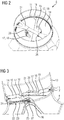
- Fig. 2 shows a first embodiment of an inventive pitch bearing arrangement 8. It comprises, see also Fig. 3 , an outer bearing ring 11 and an inner bearing ring 12 with bearing elements, for example tapered rollers or balls, being arranged between the rings 11, 12.
- the inner ring 12 is connected to the hub 4, while the outer ring 11 is connected to a root element 13 which is part of the blade 5.
- the pitch bearing arrangement 8 further comprises two reinforcement plates 14, 15 which are attached to the upper and lower end of the inner ring 11.
- the reinforcement plates 14, 15 are flat plates closing the inner of the inner bearing ring 12, see Fig. 2 .
- Each reinforcement plate 14, 15 comprises two eccentrical arranged kidney-shaped holes 17, 18, which are axially aligned with each other forming two axially corresponding hole pairs as clearly shown in Figs. 2, 3 .
- the reinforcement plates 14, 15 may be realized by two plate halfs, which are connected to each other in the middle, see the respective seams 19, 20. Each plate half comprises a respective hole 17, 18.
- the inventive pitch bearing arrangement 8 further comprises a stiffening element 21 here in form of a flat beam, which is adjacent and parallel to the outer reinforcement plate 14 and in relative close distance to the plate 14. This stiffening means 21 is attached to the outer ring 11.
- a positioning means 22 here comprising a pitch cylinder 23 is arranged within the hub 4.
- a fixation element 24 By means of a fixation element 24 it is attached to inner circumference of the hub 4 close to the lower reinforcement plate 15.
- the piston 25 which can be pushed out of the pitch cylinder 23 is connected to a mechanical connection means 26 via a pivot connection 27.
- the other end of this mechanical connection means 26 is firmly attached to the bottom side of the stiffening means 21, i.e. the flat elongated beam and extends through the corresponding holes 17, 18.
- Fig. 3 only one positioning means 22 and one mechanical connection means 26 are shown. It is to be noted, that there is certainly a second positioning means 22 and a second mechanical connection means 26 arranged at the opposite side of the hub respectively in the other pair of eccentric holes 17, 18. Both mechanical connection means 26 are shown in Fig. 2 .
- the positioning means 22 are adapted to pivot the outer ring 11 relative to the inner ring 12 and thus to pitch the blade 5 relative to the hub.
- This linear movement is transferred to the connection means 26.
- the connection means 26 rotates relative to the positioning means and moves in the holes 17, 18 allowing the outer ring 11 to be rotated.
- the positioning means and the connection means 26 are arranged in the hub and thus are accessible through the hub for maintenance purpose. There is in principle no need for the maintenance personal to enter the blade, as no relevant mechanical component is arranged in the blade but only in the hub.
- Figs. 4 and 5 show a second embodiment of an inventive pitch bearing arrangement 8.
- the hub 4 and a root element 13 are shown which are connected to each other via the pitch bearing arrangement 8 comprising the outer ring 11 attached to the root element 13 and the inner ring 12 attached to the hub 4.
- the inner ring 12 again is reinforced by two reinforcement plates 14, 15.
- Both reinforcement plates 14, 15 are designed as ring plates comprising two center holes 17, 18.
- the lower reinforcement plate 15 is a flat ring plate
- the upper reinforcement plate 14 is a cone-shaped ring plate which is connected with its inner circumference to the inner circumference of the lower reinforcement plate 15 as shown in Figs. 4 and 5 .
- a stiffening means 21 is coupled to the outer ring 11.
- the stiffening means 21 has a bent form corresponding to the form of the cone-shaped upper reinforcement plate 14, see especially Fig. 5 .
- Its center section 28 is in this embodiment double-layered and extends into the two plate holes 17, 18, so that the bottom 29 of this center section 28 corresponds to the plane in which the lower hole 18 is situated or extends even below this plane.
- a mechanical connection means 26 is eccentrically attached to the bottom side 29 of the center section 28, to which connection means 26 the positioning means 22 respectively the pitch cylinder 23 is attached with its piston 25, while the cylinder housing is attached to the hub 4 by means of a fixation element 24.
- connection means 26 the positioning means 22 respectively the pitch cylinder 23 is attached with its piston 25, while the cylinder housing is attached to the hub 4 by means of a fixation element 24.
- two positioning means 22 and two respective eccentrical connection means 26 are provided, so that also in this embodiment the rotation of the outer ring 11 relative to the non-rotating inner ring 12 and thus the pitch of the blade 5 relative to the hub 4 can be realized by symmetrical rotation force.
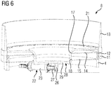
- Fig. 6 shows a third embodiment of an inventive pitch bearing arrangement 8 comprising an outer ring 11, an inner ring 12 attached to the blade route element 13 respectively the hub 4.
- the inner ring 11 is reinforced by means of reinforcement plates 14, 15, which are parallel to each other and comprise two respective center holes 17, 18 which are axially aligned.
- the pitch bearing arrangement 8 further comprises a stiffening means 21 here in form of a trough-like or pot-like shaped plate which is attached to or coupled to the outer ring 11.
- the stiffening means 21 comprises a trough-like or pot-like center section 28 extending through both holes 17, 18.
- the other end of the positioning means 22 is again attached to the hub 4 via a not shown fixation element 24.
- the position at the bottom side 29, to which the mechanical connection means 26 is attached, is eccentrical to the center axis to assure that the longitudinal movement of the piston is transferred to a rotational movement of the stiffening means 21 and thus the outer ring 11.
- a second positioning means 22 and a second mechanical connection means 26 is provided, which are arranged at a 180° position, thus also being attached eccentrical to the bottom side 29 for having a symmetrical force transfer on the stiffening means 21.
Landscapes
- Engineering & Computer Science (AREA)
- General Engineering & Computer Science (AREA)
- Mechanical Engineering (AREA)
- Life Sciences & Earth Sciences (AREA)
- Sustainable Development (AREA)
- Sustainable Energy (AREA)
- Chemical & Material Sciences (AREA)
- Combustion & Propulsion (AREA)
- Physics & Mathematics (AREA)
- Fluid Mechanics (AREA)
- Wind Motors (AREA)
Abstract
Description
- The invention relates to a pitch bearing arrangement of a wind turbine, comprising an outer bearing ring and an inner bearing ring arranged coaxially to each other and comprising a common symmetry axis, and at least one reinforcement plate arranged at the inner ring.
- Large industrial type horizontal axis wind turbines typically comprise a pitch regulation for controlling the orientation of the respective rotor blades with regard to the incoming air flow of the wind. In comparison to a stall regulated wind turbine, where the rotor blades a rigidly fixed to the hub of the wind turbine, the pitch regulated rotor blades are pivotable mounted to the hub. This allows to choose the orientation of the rotor blades with regard to the incoming air flow such that the amount of generated electricity by the wind turbine is optimized. Typically, the rotor blades are mounted to the hub by means of a bearing comprising an inner bearing ring and an outer bearing ring coaxially arranged to each other with rolling elements sandwiched between the two rings, for example tapered rollers or ball bearing arrangements. As wind turbines become larger and larger and consequently the rotor blades size increases, the forces which are transferred from the respective rotor blade to the hub via the pitch bearing increase as well. In order to reinforce the pitch bearing a reinforcement plate is arranged at the inner bearing, or in an alternative a pair of reinforcement plates is arranged at the inner bearing ring as disclosed in
EP 2 045 464 A2EP 2 933 476 A1 - Usually the rotor blade is connected to the inner ring of the bearing, while the hub is connected to the outer bearing ring. For pitching the rotor blade the pitch drive and the respective mechanic components like pitch cylinders, pitch gear etc. are arranged in the hub. For allowing the maintenance personal to access the hub for maintenance purpose the reinforcement plate comprises a manhole, whereas if two reinforcement plates are present, as disclosed in
EP 2 933 476 A1 - The object of the invention is to provide an improved pitch bearing arrangement.
- To achieve this object a pitch bearing arrangement is provided, characterized by at least one plate-like or beam-like stiffening means coupled to the outer ring axially adjacent to the at least one reinforcement plate and adapted to be coupled to a positioning means to be arranged at the other side of the at least one reinforcement plate used for pivoting the outer ring relative to the inner ring, with the at least one reinforcement plate comprising at least one hole through which the stiffening means is mechanically connectable or connected to the positioning means. In this embodiment only one reinforcement plate with at least one hole is provided.
- In a similar approach to the embodiment with only one reinforcement plate two or more reinforcement plates are provided, with the at least one stiffening means being provided adjacent to one of the reinforcement plates and the positioning means being provided adjacent to another of the reinforcement plates, with the two or more reinforcement plates comprising axially corresponding holes through which the stiffening means is mechanically connectable or connected to the positioning means. In this embodiment the at least one plate-like or beam-like stiffening member therefore is coupled to the outer ring axially adjacent to one of the reinforcement plates and adapted to be coupled to a positioning means to be arranged adjacent to the other or, in case of e.g. three or more reinforcement plates, the outermost reinforcement plate, with the reinforcement plates comprising at least two axially corresponding holes through which the stiffening means is mechanically connectable or connected to the positioning means.
- The inventive pitch bearing arrangement allows the installation of the central mechanical drive components for pitching the rotor blade in the hub, although the blade may be connected to the outer ring and the hub to the inner ring. This is possible, as the inventive pitch bearing arrangement is designed to have a mechanical connection from the inner of the hub to the inner of the blade through one or more respective connection holes provided in the one or the more reinforcement plates. The pitch bearing arrangement comprises at least one plate- or beam-like stiffening member, which is arranged at or at least mechanically coupled to the outer ring. This stiffening mean is the mechanical connection basis for coupling the outer ring to the pitch drive arranged on the other side of the reinforcement plate arrangement in the hub. In the hub the respective drive components like pitch cylinder, pitch gear etc. are arranged. This drive components are mechanically connected to the stiffening means and thus to the outer ring through a respective connection arrangement extending through the corresponding hole(s) in the reinforcement plate(s).
- As the relevant drive components in the inventive pitch bearing arrangement may now be arranged in the hub, maintenance is eased, as the maintenance personal can access these components directly in the hub, there is no need to access the blade. No large manhole(s) need(s) to be provided in the reinforcement plate(s), but only small, adapted holes for allowing the mechanical connection to the drive components in the hub. However, access ways to the blade may nevertheless also be provided in case maintenance is required in the interior of the blades.
- For connecting the stiffening means to the positioning means, a mechanical connection means is preferably provided. This mechanical connection means couples the stiffening means to the positioning means, for example the pitch cylinder or the like. Regarding the mechanical connection means several various embodiments are possible.
- According to a first embodiment, the mechanical connection means is accommodated in the one or the more holes. In this embodiment the stiffening means is flat, like a flat plate, a flat ring plate or one or more flat beams. They extend parallel to the adjacent reinforcement plate. For connecting the drive means arranged in the hub to this flat stiffening means an elongated mechanical connection means like a respective rod or the like is with one end connected to the stiffening means and with the other end to the drive means and extends through the one or the more holes of the reinforcement plate(s). The mechanical connection means is for example firmly attached to the stiffening means but pivotably attached to the drive means, for example the pitch cylinder, which pitch cylinder is attached with the other end to a respective holding means arranged at the hub.
- The one or the two or more axially corresponding holes are arranged eccentrical to the common axis, so that, when the pitch cylinder is activated and the plunger for example is pushed out of the cylinder, the respective longitudinal movement is transferred to the stiffening means resulting in a rotational movement of the outer ring and thus the blade.
- In one embodiment the one or each of the reinforcement plates comprise two single holes (in case one reinforcement plate is provided) or two pairs of holes (in case two reinforcement plates are provided) arranged equally or unequally distributed around the common axis for accommodating two connection means. In this embodiment two separate drive means are arranged in the hub, which are separately connected by separate mechanical connection means to for example a common stiffening means. For this mechanical connection two pairs of respective axially corresponding holes, through which the mechanical connection means extend, are provided in the reinforcement plates. Thus a 180° arrangement is realized. Usually both drive means are activated synchronously, so that the rotational force is transferred to the stiffening means and thus the outer ring in a symmetrical way.
- Each single hole or each hole of the one or the two pairs is in one embodiment kidney-shaped and should be as small as possible, as it is only used as a through hole for accommodating the mechanical connection means. Due to the kidney-form it follows the rotational movement performed by the mechanical connection mean due to the rotation of the stiffening member. The hole may however also resemble other shapes, e.g. circular, oval, triangular, rectangular or any other multisided shape, as long as the connection members can move freely.
- In an alternative embodiment comprising two reinforcement plates both reinforcement plates are ring-shaped and comprise axially corresponding center holes for accommodating the connection means. In this embodiment the corresponding holes are not eccentric but are center holes right in the middle of the respective plates. Nevertheless, also in this embodiment the connection means is arranged eccentrical to the common axis, as the longitudinal movement of the drive means, i.e. a pitch cylinder needs to be transferred into a rotational movement.
- Preferably also in this embodiment two separate connection means are arranged eccentrical and equally or unequally distributed around the common axis, with each connection means being connected to a separate drive means for allowing also in this embodiment to symmetrically drive the outer ring respectively the hub. In an alternative to the eccentric arrangement a centric carrier, like a tube or a rod or a block, with a gear ring connected or connectable to the positioning means may be provided.
- As already explained, in the above-mentioned embodiments the reinforcement plates are preferably parallel to each other, with the stiffening means being preferably parallel to the adjacent reinforcement plate. In an alternative the reinforcement plates may also be angled to each other.
- The previously disclosed embodiment comprises separate mechanical connection means extending through the hole or the holes provided in the reinforcement plate(s). In another embodiment of the invention comprising two or more reinforcement plates the reinforcement plates are ring-shaped and comprise axially corresponding center holes for accommodating a section of the stiffening means extending into or through the holes. In this embodiment the stiffening means is not flat but has a specific geometry providing a section which runs into or through the respective holes of the reinforcement plates. Thus, the attachment plane for attaching a connection means for connecting the stiffening means, which connection means are attached to the section bottom arranged in or below the holes, is moved to the side of the hub, where the drive components are arranged. Therefore, no elongated connection means are necessary, but only small, short connection means allowing to mechanically connect the drive means, for example the pitch cylinder, to the stiffening means section.
- The section itself is, at least in part, provided with a single wall structure, alternatively also a double wall structure may be provided.
- In this embodiment the reinforcement plate adjacent to the stiffening mean may either have a cone form, while also the stiffening mean has a corresponding cone form. The two reinforcement plates are therefore not parallel to each other. The one reinforcement plate close to the hub is flat, while the second reinforcement plate close to the blade has the cone form. The stiffening means, either in form of a cone plate or a respectively bent beam or the like, has a corresponding form, so that it is nearly parallel to the cone reinforcement plate, so that the respective section extends into or through the center holes of the reinforcement plates.
- In an alternative embodiment the reinforcement plate adjacent to the stiffening means has a flat form and the stiffening means has a trough-like form. In this embodiment, both reinforcement plates are parallel, also the stiffening means for example realized as a trough- or pot-like plate has a ring-shaped outer contour, which is parallel to the adjacent reinforcement plate, while the trough- or pot-like center extends or preferably slightly through both reinforcement plate holes.
- In any way the respective attachment plane of the section is arranged in the hole arrangement of the reinforcement plates or extends through the holes and thus lies completely below the lower reinforcement plate in the hub section.
- In any case, the respective forms of the reinforcement plates and the stiffening means are not restricted to the above-mentioned geometric forms of the various embodiments. Also, other forms or arrangements of the plate(s) and the one or more stiffening means are possible, as long as they fulfil the respective purpose.
- Aside the pitch bearing arrangement the invention relates to a wind turbine, comprising a hub, at least one rotor blade and at least one pitch bearing arrangement as disclosed above, wherein the pitch bearing arrangement pivotably connects the rotor blade to the hub.
- In a further embodiment the inventive wind turbine is characterized in that the rotor blade is attached to the outer ring and the hub to the inner ring, while that the positioning means is or are arranged inside the hub.
- The hub as referred to herein can be a segmented hub comprised of two or more separate parts e.g. for ease of casting and transportation, which are assembled to make up a full hub. Likewise, the hub as referred to herein may comprise so called hub extenders already known in the art, which are essentially cylindrical hollow bodies extending from and attached to the hub and in turn the rotor blade root attached to the extender as with regular hubs. The extender may also be referred to as a root extender. The rotor blade bearing may be attached in-between the hub and an extender but preferably placed in-between the extender and the rotor blade. In any case the pitch system as herein described is applicable to any given hub configuration i.e. a standard hub or a hub being segmented and/or comprising extenders.
- Embodiments of the invention are now described, by a way of example only, with reference to the accompanying drawings, in which:
- Fig. 1
- shows a wind turbine with pitch regulated wind turbine rotor blades,
- Fig. 2
- show a perspective view of a pitch bearing arrangement according to a first embodiment,
- Fig. 3
- shows a perspective cut view of the arrangement of
Fig. 2 , - Fig. 4
- shows a cut view of a pitch bearing arrangement of a second embodiment,
- Fig. 5
- shows a perspective cut view of the second embodiment and
- Fig. 6
- shows a cut view of a third embodiment of an inventive pitch bearing arrangement.
- In
Fig. 1 a wind turbine 1 is shown. The wind turbine 1 comprises anacelle 2 and a tower 3. Thenacelle 2 is mounted at the top of the tower 3. Thenacelle 2 is mounted rotatable with regard to the tower 3 by means of a jaw bearing. The axis of rotation of anacelle 2 with regard to the tower 3 is referred to as the jaw axis. - The wind turbine 1 furthermore comprises a
hub 4 with one or more rotor blades 5, preferably three rotor blades 5. Thehub 4 is mounted rotatable relative to thenacelle 2 by means of a main bearing. Thehub 4 is mounted rotatable about a rotor axis ofrotation 6. - The wind turbine 1 furthermore comprises a main shaft connecting the
hub 4 with a rotor of a generator 7. If thehub 4 is connected directly to the rotor, the wind turbine is referred to as a gearless, direct drive wind turbine. Alternatively, thehub 4 may also be connected to the rotor via a gear box. This type of wind turbine is commonly referred to as a geared wind turbine. - The generator 7 is accommodated within the
nacelle 2. It comprises a rotor and a stator and, as known, converts the rotational energy from the rotor into electrical energy. - In the example shown in
Fig. 1 the wind turbine 1 comprises, as said, three rotor blades 5, two of which are shown inFig. 1 . The rotor blades 5 are mounted rotatable with regard to thehub 4 by means of respectivepitch bearing arrangements 8. The rotor blades 5 may thus be pitched in order to optimize their orientation with regard to the wind flow impinging on the wind turbine 1. - Each rotor blade 5 comprises a
root section 9 and atip section 10. The root section refers to the part of the rotor blade 5 which is closest to thehub 4 and pitch bearingarrangement 8. The common set up of such a wind turbine with pitchable blades is known. -
Fig. 2 shows a first embodiment of an inventivepitch bearing arrangement 8. It comprises, see alsoFig. 3 , anouter bearing ring 11 and aninner bearing ring 12 with bearing elements, for example tapered rollers or balls, being arranged between therings inner ring 12 is connected to thehub 4, while theouter ring 11 is connected to aroot element 13 which is part of the blade 5. - The
pitch bearing arrangement 8 further comprises tworeinforcement plates inner ring 11. Thereinforcement plates inner bearing ring 12, seeFig. 2 . Eachreinforcement plate holes Figs. 2, 3 . As shown in the figures, thereinforcement plates respective seams respective hole - The inventive
pitch bearing arrangement 8 further comprises astiffening element 21 here in form of a flat beam, which is adjacent and parallel to theouter reinforcement plate 14 and in relative close distance to theplate 14. This stiffening means 21 is attached to theouter ring 11. - As
Fig. 3 shows a positioning means 22 here comprising apitch cylinder 23 is arranged within thehub 4. By means of afixation element 24 it is attached to inner circumference of thehub 4 close to thelower reinforcement plate 15. Thepiston 25 which can be pushed out of thepitch cylinder 23 is connected to a mechanical connection means 26 via apivot connection 27. The other end of this mechanical connection means 26 is firmly attached to the bottom side of the stiffening means 21, i.e. the flat elongated beam and extends through the correspondingholes Fig. 3 only one positioning means 22 and one mechanical connection means 26 are shown. It is to be noted, that there is certainly a second positioning means 22 and a second mechanical connection means 26 arranged at the opposite side of the hub respectively in the other pair ofeccentric holes Fig. 2 . - The positioning means 22 are adapted to pivot the
outer ring 11 relative to theinner ring 12 and thus to pitch the blade 5 relative to the hub. When thepistons 25 of both positioning means 22 are pushed out of the cylinder housing this linear movement is transferred to the connection means 26. Due to thepivot connection 27 the connection means 26 rotates relative to the positioning means and moves in theholes outer ring 11 to be rotated. Thus, simply by pushing thepistons 25 out or retracting them in the cylinder housing theouter ring 11 and thus the blade 5 can be pitched relative to thehub 4. - As it is obvious from
Fig. 3 the positioning means and the connection means 26 are arranged in the hub and thus are accessible through the hub for maintenance purpose. There is in principle no need for the maintenance personal to enter the blade, as no relevant mechanical component is arranged in the blade but only in the hub. -
Figs. 4 and 5 show a second embodiment of an inventivepitch bearing arrangement 8. Again thehub 4 and aroot element 13 are shown which are connected to each other via thepitch bearing arrangement 8 comprising theouter ring 11 attached to theroot element 13 and theinner ring 12 attached to thehub 4. Theinner ring 12 again is reinforced by tworeinforcement plates reinforcement plates lower reinforcement plate 15 is a flat ring plate, theupper reinforcement plate 14 is a cone-shaped ring plate which is connected with its inner circumference to the inner circumference of thelower reinforcement plate 15 as shown inFigs. 4 and 5 . - Also in this embodiment a stiffening means 21 is coupled to the
outer ring 11. The stiffening means 21 has a bent form corresponding to the form of the cone-shapedupper reinforcement plate 14, see especiallyFig. 5 . Itscenter section 28 is in this embodiment double-layered and extends into the two plate holes 17, 18, so that the bottom 29 of thiscenter section 28 corresponds to the plane in which thelower hole 18 is situated or extends even below this plane. - A mechanical connection means 26 is eccentrically attached to the
bottom side 29 of thecenter section 28, to which connection means 26 the positioning means 22 respectively thepitch cylinder 23 is attached with itspiston 25, while the cylinder housing is attached to thehub 4 by means of afixation element 24. As the cut view ofFig. 5 shows, also in this embodiment two positioning means 22 and two respective eccentrical connection means 26 are provided, so that also in this embodiment the rotation of theouter ring 11 relative to the non-rotatinginner ring 12 and thus the pitch of the blade 5 relative to thehub 4 can be realized by symmetrical rotation force. - Finally,
Fig. 6 shows a third embodiment of an inventivepitch bearing arrangement 8 comprising anouter ring 11, aninner ring 12 attached to theblade route element 13 respectively thehub 4. Theinner ring 11 is reinforced by means ofreinforcement plates - The
pitch bearing arrangement 8 further comprises a stiffening means 21 here in form of a trough-like or pot-like shaped plate which is attached to or coupled to theouter ring 11. The stiffening means 21 comprises a trough-like or pot-like center section 28 extending through bothholes bottom side 29 of this trough-like or pot-like center section 28 the mechanical connection means 26 is attached, to which via apivot connection 27 the piston of the positioning means 22, also here in form of apitch cylinder 23 is attached. The other end of the positioning means 22 is again attached to thehub 4 via a not shownfixation element 24. - The position at the
bottom side 29, to which the mechanical connection means 26 is attached, is eccentrical to the center axis to assure that the longitudinal movement of the piston is transferred to a rotational movement of the stiffening means 21 and thus theouter ring 11. - It is to be noted, that also in this embodiment a second positioning means 22 and a second mechanical connection means 26 is provided, which are arranged at a 180° position, thus also being attached eccentrical to the
bottom side 29 for having a symmetrical force transfer on the stiffening means 21. - While the embodiments show two reinforcement plates, it is also possible to provide only one reinforcement plate and to connect the stiffening means through this one plate via a hole to the positioning means provided at the other plate side, with any of the connections being usable as shown in the pictures.
- Although the present invention has been described in detail with reference to the preferred embodiment, the present invention is not limited by the disclosed examples from which the skilled person is able to derive other variations without departing from the scope of the invention.
Claims (16)
- Pitch bearing arrangement of a wind turbine (1), comprising an outer bearing ring (11) and an inner bearing ring (12) arranged coaxially to each other and comprising a common symmetry axis, and at least one reinforcement plate (14, 15) arranged at the inner ring (12) and at least one plate-like or beam-like stiffening means (21) coupled to the outer ring (11) axially adjacent to the at least one reinforcement plate (14) and adapted to be coupled to a positioning means (22) to be arranged at the other side of the at least one reinforcement plate (15) used for pivoting the outer ring (11) relative to the inner ring (12), with the at least one reinforcement plate (14, 15) comprising at least one hole (17, 18) through which the stiffening means (21) is mechanically connectable or connected to the positioning means (22).
- Pitch bearing arrangement according to claim 1, characterized in that two or more reinforcement plates (14,15) are provided, with the stiffening means being provided adjacent to one of the reinforcement plates (14) and the positioning means being provided adjacent to another of the reinforcement plates, with the reinforcement plates (14, 15) comprising axially corresponding holes (17, 18) through which the stiffening means (21) is mechanically connectable or connected to the positioning means (22).
- Pitch bearing arrangement according to claim 1 or 2, characterized in that a mechanic connection means (26) for connecting the stiffening means (21) to the positioning means (22) is provided.
- Pitch bearing arrangement according to claim 3, characterized in that the mechanic connection means (26) is accommodated in the hole or the holes (17, 18).
- Pitch bearing arrangement according to claim 4, characterized in that the hole or the corresponding holes (17, 18) are arranged eccentrical to the common axis.
- Pitch bearing arrangement according to claim 5, characterized in that the one or the more reinforcement plates (14, 15) comprise two or more pairs of holes (17, 18) arranged equally or unequally distributed around the common axis for accommodating two connection means (26).
- Pitch bearing arrangement according to claim 5 or 6, characterized in that the or each hole (17, 18) is kidney-shaped, circular, oval, triangular, rectangular or of any other multisided shape.
- Pitch bearing arrangement according claim 4, characterized in that both reinforcement plates (14, 15) are ring-shaped and comprise axially corresponding center holes (17, 18) for accommodating the connection means (26).
- Pitch bearing arrangement according to claim 8, characterized in that the connection means (26) is arranged eccentrical to the common axis, or that a centric carrier with a gear ring connected or connectable to the positioning means is provided.
- Pitch bearing according to claim 9, characterized in that two connection means (26) are arranged eccentrical and equally or unequally distributed around the common axis.
- Pitch bearing arrangement according to claim 2 or claim 2 and one of the claims 3 to 10, characterized in that the reinforcement plates (14, 15) are parallel or angled to each other, with the stiffening means (21) being preferably parallel to the adjacent reinforcement plate (14).
- Pitch bearing arrangement according to one of the claims 1 to 4, characterized in that the one or the more reinforcement plates (14, 15) are ring-shaped and that the or each reinforcement plate comprises at least one center hole (17, 18) for accommodating a section (28) of the stiffening means (21) extending into or through the hole or the holes (17, 18).
- Pitch bearing arrangement according to claim 12, characterized in that the section (28) at least in part has a single or a double wall structure.
- Pitch bearing arrangement according to claim 12 or 13, characterized in that the reinforcement plate (14) adjacent to the stiffening means (21) has a cone form and that the stiffening means (21) has a corresponding form, or that the reinforcement plate (14) adjacent to the stiffening means (21) has a flat form and the stiffening means (21) has a trough-like form.
- Wind turbine, comprising a hub (4), at least one rotor blade (5) and at least on pitch bearing arrangement (8) according to one of the preceding claims, wherein the pitch bearing arrangement (8) pivotably connects the rotor blade (5) to the hub (4).
- Wind turbine according to claim 14, characterized in that the rotor blade (5) is attached to the outer ring (11) and the hub (4) to the inner ring (12), and that the positioning means (22) is or are arranged inside the hub (4) .
Priority Applications (3)
| Application Number | Priority Date | Filing Date | Title |
|---|---|---|---|
| EP18205946.9A EP3653870B1 (en) | 2018-11-13 | 2018-11-13 | Pitch bearing arrangement |
| US16/666,533 US20200149515A1 (en) | 2018-11-13 | 2019-10-29 | Pitch bearing arrangement |
| CN201911106709.9A CN111173693B (en) | 2018-11-13 | 2019-11-13 | Pitch bearing device |
Applications Claiming Priority (1)
| Application Number | Priority Date | Filing Date | Title |
|---|---|---|---|
| EP18205946.9A EP3653870B1 (en) | 2018-11-13 | 2018-11-13 | Pitch bearing arrangement |
Publications (2)
| Publication Number | Publication Date |
|---|---|
| EP3653870A1 true EP3653870A1 (en) | 2020-05-20 |
| EP3653870B1 EP3653870B1 (en) | 2021-06-30 |
Family
ID=64308629
Family Applications (1)
| Application Number | Title | Priority Date | Filing Date |
|---|---|---|---|
| EP18205946.9A Active EP3653870B1 (en) | 2018-11-13 | 2018-11-13 | Pitch bearing arrangement |
Country Status (3)
| Country | Link |
|---|---|
| US (1) | US20200149515A1 (en) |
| EP (1) | EP3653870B1 (en) |
| CN (1) | CN111173693B (en) |
Cited By (2)
| Publication number | Priority date | Publication date | Assignee | Title |
|---|---|---|---|---|
| US12173685B2 (en) | 2021-05-10 | 2024-12-24 | Vestas Wind Systems A/S | Pitch system for a wind turbine blade |
| DE102024126999A1 (en) * | 2024-09-19 | 2026-03-19 | Thyssenkrupp Ag | Leaf bearing |
Families Citing this family (4)
| Publication number | Priority date | Publication date | Assignee | Title |
|---|---|---|---|---|
| US11454219B2 (en) * | 2019-05-10 | 2022-09-27 | General Electric Company | Rotor assembly having a pitch bearing with a stiffener ring |
| EP3786443A1 (en) * | 2019-08-30 | 2021-03-03 | General Electric Renovables España S.L. | Hub assembly for a rotor of a wind turbine |
| CN111894794B (en) * | 2020-09-10 | 2024-11-05 | 明阳智慧能源集团股份公司 | A two-blade wind turbine hub |
| EP4290070A1 (en) * | 2022-06-08 | 2023-12-13 | Siemens Gamesa Renewable Energy A/S | Pitch bearing comprising a cover plate |
Citations (5)
| Publication number | Priority date | Publication date | Assignee | Title |
|---|---|---|---|---|
| EP2045464A2 (en) | 2007-10-01 | 2009-04-08 | Siemens Aktiengesellschaft | Pitch bearing for wind turbine rotor blades |
| US20090311104A1 (en) * | 2006-11-13 | 2009-12-17 | Ulrik Steffensen | Reinforced bearing for a wind-power generator blade |
| DE202010009462U1 (en) * | 2009-06-25 | 2010-09-09 | Bonfiglioli Riduttori S.P.A. | Assembly for controlling a blade pitch of a wind generator |
| EP2643585A1 (en) * | 2010-11-26 | 2013-10-02 | Vestas Wind Systems A/S | A pitch system for a wind turbine |
| EP2933476A1 (en) | 2014-04-17 | 2015-10-21 | Siemens Aktiengesellschaft | Reinforced pitch bearing of a wind turbine |
Family Cites Families (4)
| Publication number | Priority date | Publication date | Assignee | Title |
|---|---|---|---|---|
| DK1995454T3 (en) * | 2007-05-25 | 2016-06-13 | Siemens Ag | Device for regulating the inclination angle of a rotor blade of a wind turbine |
| EP3098441B1 (en) * | 2015-05-27 | 2022-12-28 | Siemens Gamesa Renewable Energy A/S | Pitch system locking arrangement |
| DK3267033T3 (en) * | 2016-07-06 | 2019-07-01 | Siemens Gamesa Renewable Energy As | WINDMILL |
| CN207777065U (en) * | 2017-12-18 | 2018-08-28 | 北京金风科创风电设备有限公司 | Hydraulic variable propeller system and wind power generating set |
-
2018
- 2018-11-13 EP EP18205946.9A patent/EP3653870B1/en active Active
-
2019
- 2019-10-29 US US16/666,533 patent/US20200149515A1/en not_active Abandoned
- 2019-11-13 CN CN201911106709.9A patent/CN111173693B/en active Active
Patent Citations (5)
| Publication number | Priority date | Publication date | Assignee | Title |
|---|---|---|---|---|
| US20090311104A1 (en) * | 2006-11-13 | 2009-12-17 | Ulrik Steffensen | Reinforced bearing for a wind-power generator blade |
| EP2045464A2 (en) | 2007-10-01 | 2009-04-08 | Siemens Aktiengesellschaft | Pitch bearing for wind turbine rotor blades |
| DE202010009462U1 (en) * | 2009-06-25 | 2010-09-09 | Bonfiglioli Riduttori S.P.A. | Assembly for controlling a blade pitch of a wind generator |
| EP2643585A1 (en) * | 2010-11-26 | 2013-10-02 | Vestas Wind Systems A/S | A pitch system for a wind turbine |
| EP2933476A1 (en) | 2014-04-17 | 2015-10-21 | Siemens Aktiengesellschaft | Reinforced pitch bearing of a wind turbine |
Cited By (2)
| Publication number | Priority date | Publication date | Assignee | Title |
|---|---|---|---|---|
| US12173685B2 (en) | 2021-05-10 | 2024-12-24 | Vestas Wind Systems A/S | Pitch system for a wind turbine blade |
| DE102024126999A1 (en) * | 2024-09-19 | 2026-03-19 | Thyssenkrupp Ag | Leaf bearing |
Also Published As
| Publication number | Publication date |
|---|---|
| CN111173693A (en) | 2020-05-19 |
| CN111173693B (en) | 2023-10-10 |
| EP3653870B1 (en) | 2021-06-30 |
| US20200149515A1 (en) | 2020-05-14 |
Similar Documents
| Publication | Publication Date | Title |
|---|---|---|
| EP3653870B1 (en) | Pitch bearing arrangement | |
| AU2010339143B2 (en) | Wind turbine | |
| EP1882854B1 (en) | Apparatus for assembling rotary machines | |
| DK178606B1 (en) | Mounting structure with a rotary for a wind turbine rotor blade and associated design methods | |
| US7857599B2 (en) | Method and apparatus for forming wind turbine machines | |
| CN102032113B (en) | Systems and methods for assembling a pitch control assembly for use in a wind turbine | |
| US9915245B2 (en) | Reinforced pitch bearing of a wind turbine | |
| EP2302212A1 (en) | Blade pitch angle control device and wind turbine generator | |
| JP6719592B2 (en) | Wind turbine generator including rotor blade for wind turbine and the same | |
| US20090317256A1 (en) | Rotor hub of a wind energy plant | |
| US10844833B2 (en) | Blade adapter for wind turbines | |
| JP2013534592A (en) | Vertical axis windmill | |
| US8779620B1 (en) | Rotary windmill power generator | |
| EP2859220B1 (en) | Improvements relating to wind turbines | |
| JP4875770B2 (en) | Windmill semi-flexible mount | |
| EP1933027A1 (en) | Hub for the rotor of a wind turbine | |
| JP7600100B2 (en) | Rotor bearing housing and wind turbine comprising rotor bearing housing - Patents.com | |
| EP2617991A1 (en) | Vertical axis wind turbine | |
| EP3163073A1 (en) | Device for changing the angle of inclination in wind turbines | |
| US11788514B2 (en) | Wind power plant with supporting structure | |
| WO2014161607A1 (en) | A hub and bearing system and a turbine comprising the hub and bearing system | |
| EP2981713B1 (en) | A hub and bearing system and a turbine comprising the hub and bearing system | |
| EP3267032B1 (en) | Blade bearing arrangement for a wind turbine |
Legal Events
| Date | Code | Title | Description |
|---|---|---|---|
| PUAI | Public reference made under article 153(3) epc to a published international application that has entered the european phase |
Free format text: ORIGINAL CODE: 0009012 |
|
| STAA | Information on the status of an ep patent application or granted ep patent |
Free format text: STATUS: THE APPLICATION HAS BEEN PUBLISHED |
|
| AK | Designated contracting states |
Kind code of ref document: A1 Designated state(s): AL AT BE BG CH CY CZ DE DK EE ES FI FR GB GR HR HU IE IS IT LI LT LU LV MC MK MT NL NO PL PT RO RS SE SI SK SM TR |
|
| AX | Request for extension of the european patent |
Extension state: BA ME |
|
| STAA | Information on the status of an ep patent application or granted ep patent |
Free format text: STATUS: REQUEST FOR EXAMINATION WAS MADE |
|
| 17P | Request for examination filed |
Effective date: 20201117 |
|
| RBV | Designated contracting states (corrected) |
Designated state(s): AL AT BE BG CH CY CZ DE DK EE ES FI FR GB GR HR HU IE IS IT LI LT LU LV MC MK MT NL NO PL PT RO RS SE SI SK SM TR |
|
| GRAP | Despatch of communication of intention to grant a patent |
Free format text: ORIGINAL CODE: EPIDOSNIGR1 |
|
| STAA | Information on the status of an ep patent application or granted ep patent |
Free format text: STATUS: GRANT OF PATENT IS INTENDED |
|
| INTG | Intention to grant announced |
Effective date: 20210203 |
|
| GRAS | Grant fee paid |
Free format text: ORIGINAL CODE: EPIDOSNIGR3 |
|
| GRAA | (expected) grant |
Free format text: ORIGINAL CODE: 0009210 |
|
| STAA | Information on the status of an ep patent application or granted ep patent |
Free format text: STATUS: THE PATENT HAS BEEN GRANTED |
|
| AK | Designated contracting states |
Kind code of ref document: B1 Designated state(s): AL AT BE BG CH CY CZ DE DK EE ES FI FR GB GR HR HU IE IS IT LI LT LU LV MC MK MT NL NO PL PT RO RS SE SI SK SM TR |
|
| REG | Reference to a national code |
Ref country code: CH Ref legal event code: EP |
|
| REG | Reference to a national code |
Ref country code: AT Ref legal event code: REF Ref document number: 1406572 Country of ref document: AT Kind code of ref document: T Effective date: 20210715 |
|
| REG | Reference to a national code |
Ref country code: DE Ref legal event code: R096 Ref document number: 602018019283 Country of ref document: DE |
|
| REG | Reference to a national code |
Ref country code: IE Ref legal event code: FG4D |
|
| REG | Reference to a national code |
Ref country code: NL Ref legal event code: FP |
|
| REG | Reference to a national code |
Ref country code: LT Ref legal event code: MG9D |
|
| PG25 | Lapsed in a contracting state [announced via postgrant information from national office to epo] |
Ref country code: BG Free format text: LAPSE BECAUSE OF FAILURE TO SUBMIT A TRANSLATION OF THE DESCRIPTION OR TO PAY THE FEE WITHIN THE PRESCRIBED TIME-LIMIT Effective date: 20210930 Ref country code: FI Free format text: LAPSE BECAUSE OF FAILURE TO SUBMIT A TRANSLATION OF THE DESCRIPTION OR TO PAY THE FEE WITHIN THE PRESCRIBED TIME-LIMIT Effective date: 20210630 Ref country code: HR Free format text: LAPSE BECAUSE OF FAILURE TO SUBMIT A TRANSLATION OF THE DESCRIPTION OR TO PAY THE FEE WITHIN THE PRESCRIBED TIME-LIMIT Effective date: 20210630 |
|
| REG | Reference to a national code |
Ref country code: AT Ref legal event code: MK05 Ref document number: 1406572 Country of ref document: AT Kind code of ref document: T Effective date: 20210630 |
|
| PG25 | Lapsed in a contracting state [announced via postgrant information from national office to epo] |
Ref country code: RS Free format text: LAPSE BECAUSE OF FAILURE TO SUBMIT A TRANSLATION OF THE DESCRIPTION OR TO PAY THE FEE WITHIN THE PRESCRIBED TIME-LIMIT Effective date: 20210630 Ref country code: SE Free format text: LAPSE BECAUSE OF FAILURE TO SUBMIT A TRANSLATION OF THE DESCRIPTION OR TO PAY THE FEE WITHIN THE PRESCRIBED TIME-LIMIT Effective date: 20210630 Ref country code: NO Free format text: LAPSE BECAUSE OF FAILURE TO SUBMIT A TRANSLATION OF THE DESCRIPTION OR TO PAY THE FEE WITHIN THE PRESCRIBED TIME-LIMIT Effective date: 20210930 Ref country code: LV Free format text: LAPSE BECAUSE OF FAILURE TO SUBMIT A TRANSLATION OF THE DESCRIPTION OR TO PAY THE FEE WITHIN THE PRESCRIBED TIME-LIMIT Effective date: 20210630 Ref country code: GR Free format text: LAPSE BECAUSE OF FAILURE TO SUBMIT A TRANSLATION OF THE DESCRIPTION OR TO PAY THE FEE WITHIN THE PRESCRIBED TIME-LIMIT Effective date: 20211001 |
|
| PG25 | Lapsed in a contracting state [announced via postgrant information from national office to epo] |
Ref country code: SK Free format text: LAPSE BECAUSE OF FAILURE TO SUBMIT A TRANSLATION OF THE DESCRIPTION OR TO PAY THE FEE WITHIN THE PRESCRIBED TIME-LIMIT Effective date: 20210630 Ref country code: SM Free format text: LAPSE BECAUSE OF FAILURE TO SUBMIT A TRANSLATION OF THE DESCRIPTION OR TO PAY THE FEE WITHIN THE PRESCRIBED TIME-LIMIT Effective date: 20210630 Ref country code: EE Free format text: LAPSE BECAUSE OF FAILURE TO SUBMIT A TRANSLATION OF THE DESCRIPTION OR TO PAY THE FEE WITHIN THE PRESCRIBED TIME-LIMIT Effective date: 20210630 Ref country code: ES Free format text: LAPSE BECAUSE OF FAILURE TO SUBMIT A TRANSLATION OF THE DESCRIPTION OR TO PAY THE FEE WITHIN THE PRESCRIBED TIME-LIMIT Effective date: 20210630 Ref country code: RO Free format text: LAPSE BECAUSE OF FAILURE TO SUBMIT A TRANSLATION OF THE DESCRIPTION OR TO PAY THE FEE WITHIN THE PRESCRIBED TIME-LIMIT Effective date: 20210630 Ref country code: PT Free format text: LAPSE BECAUSE OF FAILURE TO SUBMIT A TRANSLATION OF THE DESCRIPTION OR TO PAY THE FEE WITHIN THE PRESCRIBED TIME-LIMIT Effective date: 20211102 Ref country code: AT Free format text: LAPSE BECAUSE OF FAILURE TO SUBMIT A TRANSLATION OF THE DESCRIPTION OR TO PAY THE FEE WITHIN THE PRESCRIBED TIME-LIMIT Effective date: 20210630 Ref country code: CZ Free format text: LAPSE BECAUSE OF FAILURE TO SUBMIT A TRANSLATION OF THE DESCRIPTION OR TO PAY THE FEE WITHIN THE PRESCRIBED TIME-LIMIT Effective date: 20210630 |
|
| PG25 | Lapsed in a contracting state [announced via postgrant information from national office to epo] |
Ref country code: PL Free format text: LAPSE BECAUSE OF FAILURE TO SUBMIT A TRANSLATION OF THE DESCRIPTION OR TO PAY THE FEE WITHIN THE PRESCRIBED TIME-LIMIT Effective date: 20210630 |
|
| REG | Reference to a national code |
Ref country code: DE Ref legal event code: R097 Ref document number: 602018019283 Country of ref document: DE |
|
| PG25 | Lapsed in a contracting state [announced via postgrant information from national office to epo] |
Ref country code: DK Free format text: LAPSE BECAUSE OF FAILURE TO SUBMIT A TRANSLATION OF THE DESCRIPTION OR TO PAY THE FEE WITHIN THE PRESCRIBED TIME-LIMIT Effective date: 20210630 |
|
| PLBE | No opposition filed within time limit |
Free format text: ORIGINAL CODE: 0009261 |
|
| STAA | Information on the status of an ep patent application or granted ep patent |
Free format text: STATUS: NO OPPOSITION FILED WITHIN TIME LIMIT |
|
| PG25 | Lapsed in a contracting state [announced via postgrant information from national office to epo] |
Ref country code: AL Free format text: LAPSE BECAUSE OF FAILURE TO SUBMIT A TRANSLATION OF THE DESCRIPTION OR TO PAY THE FEE WITHIN THE PRESCRIBED TIME-LIMIT Effective date: 20210630 |
|
| 26N | No opposition filed |
Effective date: 20220331 |
|
| PG25 | Lapsed in a contracting state [announced via postgrant information from national office to epo] |
Ref country code: MC Free format text: LAPSE BECAUSE OF FAILURE TO SUBMIT A TRANSLATION OF THE DESCRIPTION OR TO PAY THE FEE WITHIN THE PRESCRIBED TIME-LIMIT Effective date: 20210630 |
|
| REG | Reference to a national code |
Ref country code: CH Ref legal event code: PL |
|
| PG25 | Lapsed in a contracting state [announced via postgrant information from national office to epo] |
Ref country code: LU Free format text: LAPSE BECAUSE OF NON-PAYMENT OF DUE FEES Effective date: 20211113 Ref country code: IT Free format text: LAPSE BECAUSE OF FAILURE TO SUBMIT A TRANSLATION OF THE DESCRIPTION OR TO PAY THE FEE WITHIN THE PRESCRIBED TIME-LIMIT Effective date: 20210630 Ref country code: BE Free format text: LAPSE BECAUSE OF NON-PAYMENT OF DUE FEES Effective date: 20211130 |
|
| REG | Reference to a national code |
Ref country code: BE Ref legal event code: MM Effective date: 20211130 |
|
| REG | Reference to a national code |
Ref country code: DE Ref legal event code: R082 Ref document number: 602018019283 Country of ref document: DE Representative=s name: SAUTHOFF, KARSTEN, DIPL.-ING. UNIV., DE |
|
| PG25 | Lapsed in a contracting state [announced via postgrant information from national office to epo] |
Ref country code: IE Free format text: LAPSE BECAUSE OF NON-PAYMENT OF DUE FEES Effective date: 20211113 |
|
| PG25 | Lapsed in a contracting state [announced via postgrant information from national office to epo] |
Ref country code: LT Free format text: LAPSE BECAUSE OF FAILURE TO SUBMIT A TRANSLATION OF THE DESCRIPTION OR TO PAY THE FEE WITHIN THE PRESCRIBED TIME-LIMIT Effective date: 20210630 |
|
| PG25 | Lapsed in a contracting state [announced via postgrant information from national office to epo] |
Ref country code: CY Free format text: LAPSE BECAUSE OF FAILURE TO SUBMIT A TRANSLATION OF THE DESCRIPTION OR TO PAY THE FEE WITHIN THE PRESCRIBED TIME-LIMIT Effective date: 20210630 |
|
| PG25 | Lapsed in a contracting state [announced via postgrant information from national office to epo] |
Ref country code: LI Free format text: LAPSE BECAUSE OF NON-PAYMENT OF DUE FEES Effective date: 20220701 Ref country code: HU Free format text: LAPSE BECAUSE OF FAILURE TO SUBMIT A TRANSLATION OF THE DESCRIPTION OR TO PAY THE FEE WITHIN THE PRESCRIBED TIME-LIMIT; INVALID AB INITIO Effective date: 20181113 Ref country code: CH Free format text: LAPSE BECAUSE OF NON-PAYMENT OF DUE FEES Effective date: 20220701 |
|
| PG25 | Lapsed in a contracting state [announced via postgrant information from national office to epo] |
Ref country code: MK Free format text: LAPSE BECAUSE OF FAILURE TO SUBMIT A TRANSLATION OF THE DESCRIPTION OR TO PAY THE FEE WITHIN THE PRESCRIBED TIME-LIMIT Effective date: 20210630 |
|
| PG25 | Lapsed in a contracting state [announced via postgrant information from national office to epo] |
Ref country code: MT Free format text: LAPSE BECAUSE OF FAILURE TO SUBMIT A TRANSLATION OF THE DESCRIPTION OR TO PAY THE FEE WITHIN THE PRESCRIBED TIME-LIMIT Effective date: 20210630 |
|
| PGFP | Annual fee paid to national office [announced via postgrant information from national office to epo] |
Ref country code: GB Payment date: 20250901 Year of fee payment: 8 |
|
| PG25 | Lapsed in a contracting state [announced via postgrant information from national office to epo] |
Ref country code: TR Free format text: LAPSE BECAUSE OF FAILURE TO SUBMIT A TRANSLATION OF THE DESCRIPTION OR TO PAY THE FEE WITHIN THE PRESCRIBED TIME-LIMIT Effective date: 20210630 |
|
| PGFP | Annual fee paid to national office [announced via postgrant information from national office to epo] |
Ref country code: NL Payment date: 20251124 Year of fee payment: 8 |
|
| PGFP | Annual fee paid to national office [announced via postgrant information from national office to epo] |
Ref country code: DE Payment date: 20250731 Year of fee payment: 8 |
|
| PGFP | Annual fee paid to national office [announced via postgrant information from national office to epo] |
Ref country code: FR Payment date: 20251124 Year of fee payment: 8 |